Embed Size (px)
Citation preview
FLEXURAL BEHAVIOR OF FRP-REINFORCED CONCRETE MEMBERS
By
Alkhrdaji, Mettemeyer, Belarbi and Nanni
University of Missouri-Rolla
CIES 99-15
CENTER FOR INFRASTRUCTURE
ENGINEERING STUDIES
Disclaimer The contents of this report reflect the views of the author(s), who are responsible
for the facts and the accuracy of information presented herein. This document is
disseminated under the sponsorship of the Center for Infrastructure Engineering
Studies (CIES), University of Missouri-Rolla, in the interest of information
exchange. CIES assumes no liability for the contents or use thereof.

The mission of CIES is to provide leadership in research and education for solving society's problems affecting the nation's infrastructure systems. CIES is the primary conduit for communication among those on the UMR campus interested in infrastructure studies and provides coordination for collaborative efforts. CIES activities include interdisciplinary research and development with projects tailored to address needs of federal agencies, state agencies, and private industry as well as technology transfer and continuing/distance education to the engineering community and industry.
Center for Infrastructure Engineering Studies (CIES) University of Missouri-Rolla
223 Engineering Research Lab 1870 Miner Circle
Rolla, MO 65409-0710 Tel: (573) 341-6223; fax -6215
E-mail: [email protected] http://www.cies.umr.edu
Alkhrdaji, Mettemeyer, Nanni, and Belarbi, “Flexural Behavior of FRP-Reinforced Concrete Members “.
1
1. INTRODUCTION
Many structures, such as bridges and parking garages, are usually treated with deicing salts and are, therefore, subjected to an aggressive environment. For such structures, possible corrosion of reinforcing and prestressing steel may eventually lead to concrete deterioration and loss of serviceability or capacity. To control corrosion problems, professionals have turned to alternative reinforcements such as epoxy-coated steel bars. However, such remedies were only found to slow down, rather than eliminate corrosion problems. Recently, fiber reinforced polymer (FRP) materials have emerged as an alternative to steel reinforcement. FRP materials are corrosion resistance and exhibit several properties that make them suitable as structural reinforcement (ACI Committee 440, 1996 and Japan Society of Civil Engineers (JSCE), 1997). In order to apply this new technology to practice, a better understanding of the behavior of FRP reinforced members is required. In addition, current codes provide no guidance on how to modify the existing requirements when reinforcing with materials other than steel.
Some of the main differences of FRP reinforcement when compared to steel reinforcement are higher tensile strength, lower stiffness, and elastic behavior up to failure with no yielding (no plasticity). These differences are reflected on the flexural behavior of FRP-reinforced members. The conventional concept of under-reinforced members as a favorable design approach is not practical for FRP-reinforced members because it will result in members having lower stiffness hence, larger deflection and crack widths are expected.
Available experimental results of FRP reinforced sections indicate that when FRP reinforcing bars ruptured (tension-controlled failure), the failure was sudden and led to the collapse of the member (Nanni, 1993; GangaRao and Vijay, 1997; and Theriault and Benmokrane, 1998). However, a more progressive and less catastrophic failure was observed when the member failed due to the crushing of concrete (compression-controlled failure). This behavior results in higher deformability, which is defined as the ratio of energy absorption (area under moment-curvature curve) at ultimate to that at service level (Jaeger et al., 1997).
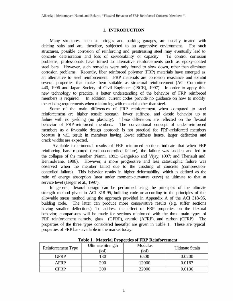
In general, flexural design can be performed using the principles of the ultimate strength method given in ACI 318-95, building code or according to the principles of the allowable stress method using the approach provided in Appendix A of the ACI 318-95, building code. The latter can produce more conservative results (e.g. stiffer sections having smaller deflections). To address the effect of FRP properties on the flexural behavior, comparisons will be made for sections reinforced with the three main types of FRP reinforcement namely, glass (GFRP), aramid (AFRP), and carbon (CFRP). The properties of the three types considered hereafter are given in Table 1. These are typical properties of FRP bars available in the market today.
Table 1. Material Properties of FRP Reinforcement
Reinforcement Type Ultimate Strength (ksi)
Modulus (ksi)
Ultimate Strain
GFRP 130 6500 0.0200 AFRP 200 12000 0.0167 CFRP 300 22000 0.0136
Alkhrdaji, Mettemeyer, Nanni, and Belarbi, “Flexural Behavior of FRP-Reinforced Concrete Members “.
2
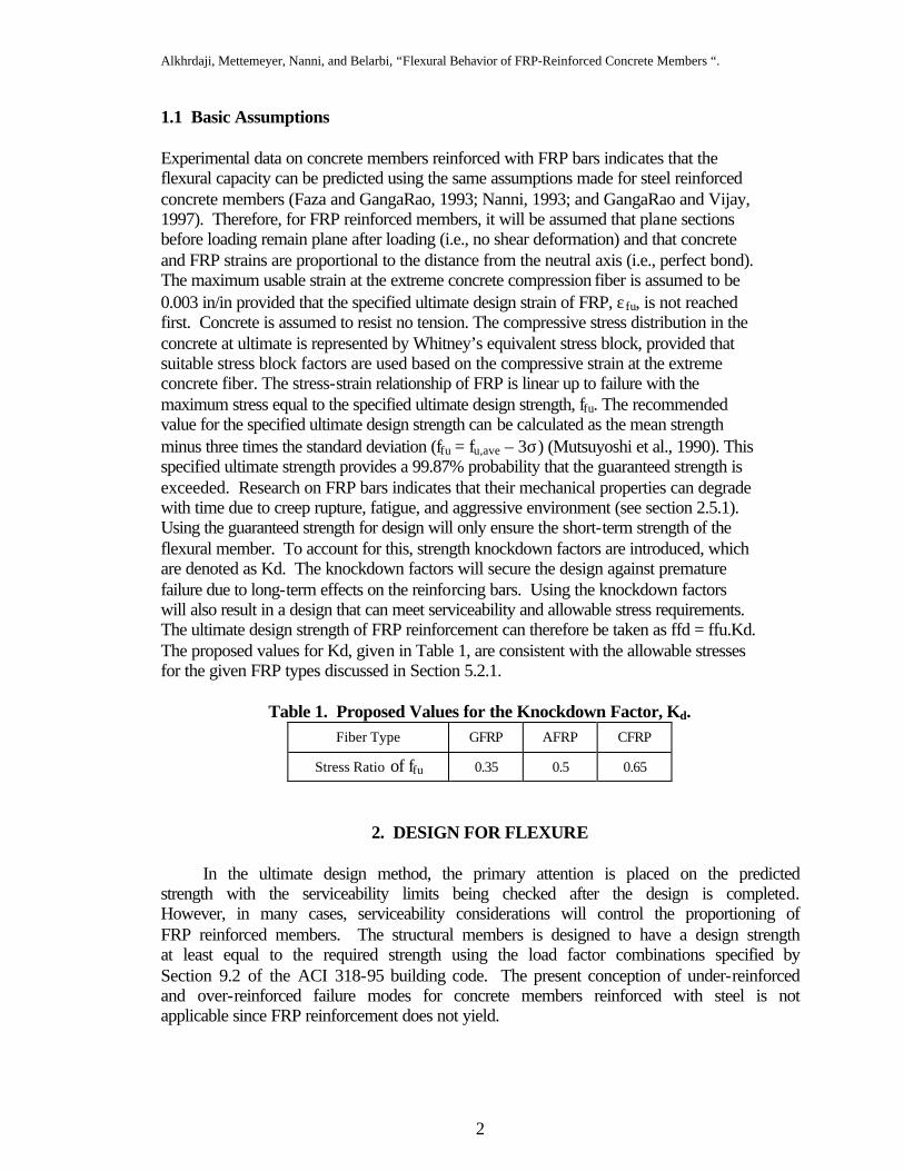
1.1 Basic Assumptions Experimental data on concrete members reinforced with FRP bars indicates that the flexural capacity can be predicted using the same assumptions made for steel reinforced concrete members (Faza and GangaRao, 1993; Nanni, 1993; and GangaRao and Vijay, 1997). Therefore, for FRP reinforced members, it will be assumed that plane sections before loading remain plane after loading (i.e., no shear deformation) and that concrete and FRP strains are proportional to the distance from the neutral axis (i.e., perfect bond). The maximum usable strain at the extreme concrete compression fiber is assumed to be 0.003 in/in provided that the specified ultimate design strain of FRP, εfu, is not reached first. Concrete is assumed to resist no tension. The compressive stress distribution in the concrete at ultimate is represented by Whitney’s equivalent stress block, provided that suitable stress block factors are used based on the compressive strain at the extreme concrete fiber. The stress-strain relationship of FRP is linear up to failure with the maximum stress equal to the specified ultimate design strength, ffu. The recommended value for the specified ultimate design strength can be calculated as the mean strength minus three times the standard deviation (ffu = fu,ave – 3σ) (Mutsuyoshi et al., 1990). This specified ultimate strength provides a 99.87% probability that the guaranteed strength is exceeded. Research on FRP bars indicates that their mechanical properties can degrade with time due to creep rupture, fatigue, and aggressive environment (see section 2.5.1). Using the guaranteed strength for design will only ensure the short-term strength of the flexural member. To account for this, strength knockdown factors are introduced, which are denoted as Kd. The knockdown factors will secure the design against premature failure due to long-term effects on the reinforcing bars. Using the knockdown factors will also result in a design that can meet serviceability and allowable stress requirements. The ultimate design strength of FRP reinforcement can therefore be taken as ffd = ffu.Kd. The proposed values for Kd, given in Table 1, are consistent with the allowable stresses for the given FRP types discussed in Section 5.2.1.
Table 1. Proposed Values for the Knockdown Factor, Kd.
Fiber Type GFRP AFRP CFRP
Stress Ratio of ffu 0.35 0.5 0.65
2. DESIGN FOR FLEXURE
In the ultimate design method, the primary attention is placed on the predicted strength with the serviceability limits being checked after the design is completed. However, in many cases, serviceability considerations will control the proportioning of FRP reinforced members. The structural members is designed to have a design strength at least equal to the required strength using the load factor combinations specified by Section 9.2 of the ACI 318-95 building code. The present conception of under-reinforced and over-reinforced failure modes for concrete members reinforced with steel is not applicable since FRP reinforcement does not yield.
Alkhrdaji, Mettemeyer, Nanni, and Belarbi, “Flexural Behavior of FRP-Reinforced Concrete Members “.
3
2.1. Safety Factor for Flexure (φ Factor)
Due to the limited data available on service and long-term performance of FRP composites in concrete structures, a more conservative value for the φ factor for flexural design should be adopted. The Japanese recommendations for design of flexural members using FRP suggest a material reduction factor of 1/1.3 for glass FRP reinforcement and 1/1.15 for carbon and aramid FRP reinforcement (Japan Society of Civil Engineers, 1997). ACI Committee 318 suggests that a lower safety factor should be used for compression–controlled sections than is used for tension-controlled section because compression–controlled sections generally have less ductility and are more sensitive to variations in concrete strength. Therefore, a φ factor of 0.7 is suggested for the flexural design of FRP reinforced members. It should be recognized however that for most FRP reinforced systems, service requirements control the design and a φ factor of 0.7 is not too restrictive. 2.2. Stress of FRP Reinforcement
The capacity of steel reinforced concrete members is calculated based on the assumption that all tension reinforcement yield at ultimate. Therefore, the tension force is assumed to act at the centroid of the reinforcement with a magnitude equal to the area of tension reinforcement multiplied by the yield strength of steel. This assumption is valid for steel reinforcement arranged in one layer or multiple layers. FRP materials, on the other hand, have no plastic region. The stress in each layer of the FRP reinforcement will vary depending on its distance from the neutral axis. In this case, the flexural capacity must be based on a strain compatibility approach. When using a single type of FRP reinforcement, the outermost layer controls reinforcement failure. Similarly, if different types of FRP bars are used to reinforce the same member, the variation in the stress level in each bar type must be considered when calculating the flexural capacity. Unless concrete crushing controls, the layer that reaches it capacity first controls the capacity of the member.
The failure mode controlled by the rupture of FRP bars is catastrophic and therefore undesirable. For this reason, members reinforced with FRP should be so proportioned to ensure a compression failure (Nanni, 1993). However, for some non-rectangular sections (e.g., T sections), space limitations may not allow for the placement of sufficient FRP reinforcement to over-reinforce the member. In such cases, under-reinforced sections may be used if an appropriate safety factor is included and serviceability requirements are satisfied.
ACI Committee 318 (1995) specifies that the maximum amount of reinforcement in steel reinforced concrete sections is limited to 75 percent of the amount of reinforcement at the balanced strain condition. This limit was set to consistently ensure yielding of reinforcement prior to crushing of concrete. Analogous limit can be set when designing with FRP reinforcement to attempt to ensure the crushing of concrete (compression-controlled failure). To achieve this, the amount of FRP reinforcement should be larger than the balanced amount, ρf,b. However, It should be noted that if the concrete strength is higher than the design strength (as it may occur because of production or age), FRP
Alkhrdaji, Mettemeyer, Nanni, and Belarbi, “Flexural Behavior of FRP-Reinforced Concrete Members “.
4
rupture could become the controlling failure mode. The safety limit can be set as 1/0.75 or 1.33 and the minimum amount of FRP reinforcement is such that:
b,fmin,f 331. ρ=ρ (1) where
fucuf
cuf
fu
c1b,f fE
Ef'f
85.0+ε
εβ=ρ (2)
in which, εcu is the ultimate permissible strain in concrete taken as 0.003, as shown in Figure 1. Utilizing equilibrium and compatibility requirements, the relationship between the ratio of FRP reinforcement and the stress in the reinforcement can be expressed as follows:
fcuf
cuf
f
c1f feE
eEff'
ß0.85?+
= (3)
Dividing Equation (3) by Equation (2) yields the following expression:
fu
cu
fu
f
fu
cu
f
fu
bf,
f
ee
ff
ee
1
ff
??
+
+= (4)
Equation (4) is only valid for the purpose of verifying the short-term behavior of FRP reinforced members (e.g., laboratory experiments). For design purposes, the ultimate design strength of FRP bars should account for two factors. The first, is the low allowable stress at service level, which can be as low as 20% of the ultimate strength of a bar (see Section 2.5.1), and the second, is satisfying serviceability requirements.
Generally, FRP bars have lower stiffness than steel reinforcement, resulting in larger deflections and wider cracks. To these effects, the strength knockdown factor can result in more practical designs that can satisfy the allowable stress and meet serviceability requirements. The knockdown factor, Kd, is used to calculate a conservative ultimate design strength ffd, from which the corresponding design strain ef,d is determined. Examining Equation (2) indicate that the relationship between the balanced amount of reinforcement and the strength of FRP bars is not linear and the change in the balanced reinforcement ratio rf,b is not proportional to the reduction in the ultimate strength. For the three types of FRP bars considered in this document (GFRP, AFRP, and CFRP) and
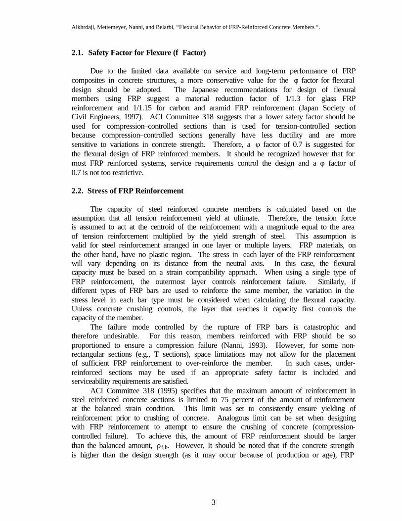
Figure 1. Flexural stress and strain diagrams at balanced strain condition.
εcu = 0.003
cb
N.A. ab =β1cb 0.85 f′c bab
Af,b ffu εf,u
Af,b
d
b

Alkhrdaji, Mettemeyer, Nanni, and Belarbi, “Flexural Behavior of FRP-Reinforced Concrete Members “.
5
considering a 5000 psi concrete, introducing Kd values of 0.35, 0.5, and 0.65 (given in Table 2) will cause rf,b to increase 5.0, 2.6, and 1.6 times, respectively. The larger value obtained for glass FRP bars reflects the inferior long-term properties and lower stiffness of this type of reinforcement. Figure (2) shows the effect of the knockdown factor on the relationship between ff/ffu and rf/rf,b for over-reinforced members.
Similarly, the relation between ff/ff,d and rf/rf,b is obtained by substituted for ff,u and ef,u by the corresponding design values of ff,d and ef,d in Equation (4), which yields the following
expression:
fd
cu
fd
f
fd
cu
f
fd
bf,
f
ee
ff
ee
1
ff
??
+
+= (5)
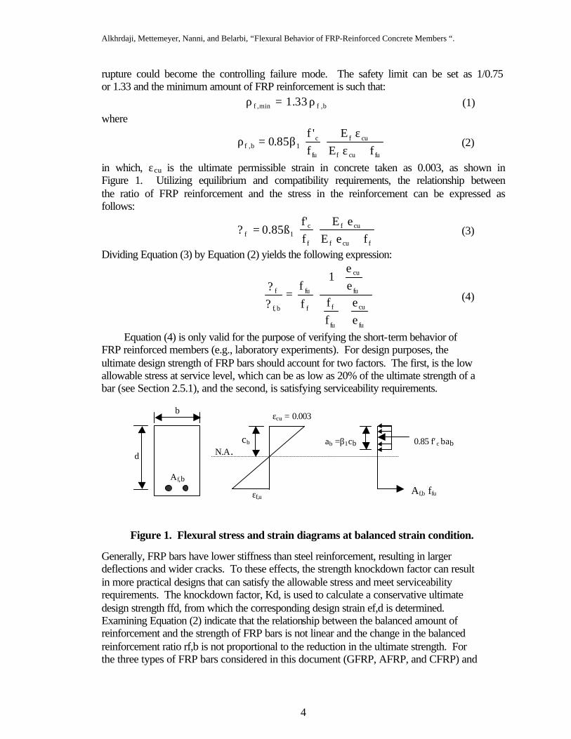
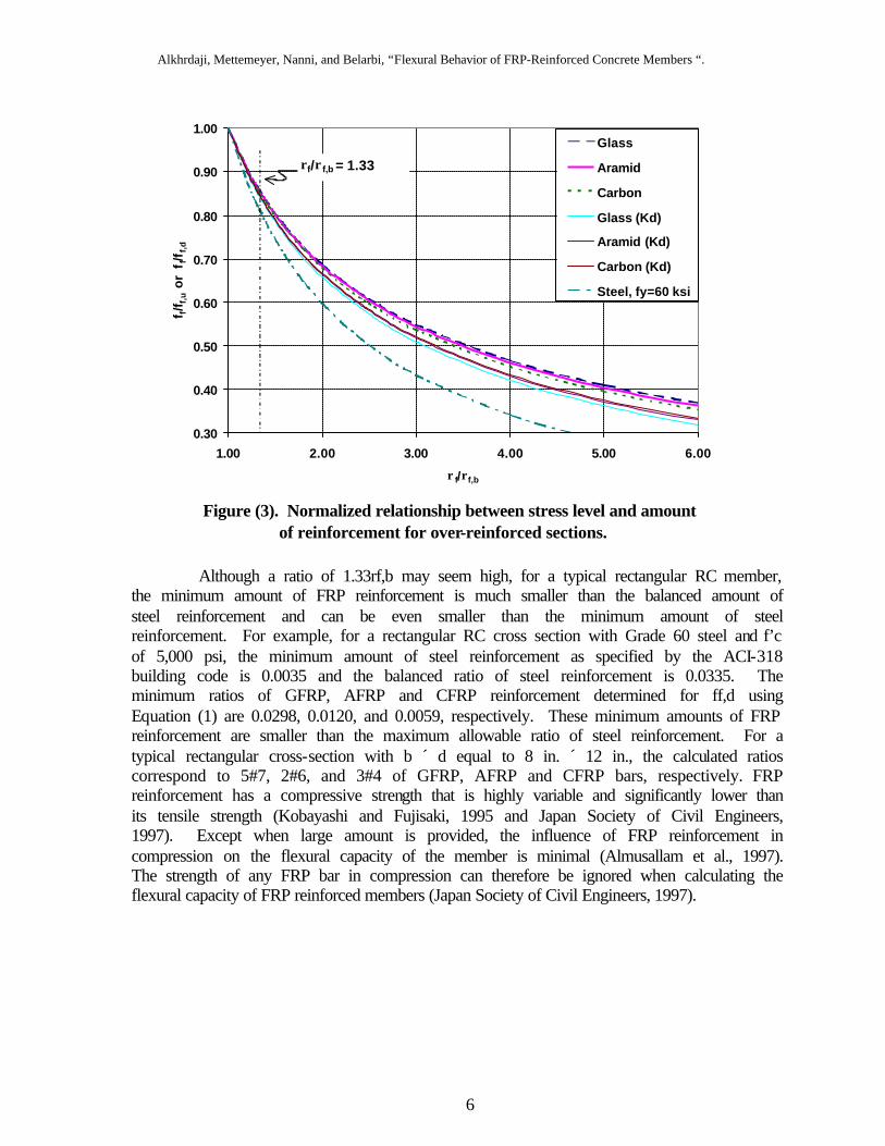
Equations (4) and (5) are plotted in Figure 3 for the three different types of FRP bars namely, glass, aramid and carbon. Also plotted in Figure 3 is the relation between fs/fy and rs/rb for steel bars with fy of 60 ksi. The figure clearly indicates that for typical cross-sections, imposing a reinforcement ratio of 1.33rf,b will limit the tensile stress in the FRP reinforcement at ultimate to a value of 0.86ffu for Equation (4) and 0.85ffd for Equation (5) while for steel, a reinforcement ratio of 1.33rb will correspond to a stress of 0.8fy. The resulting stress limits in FRP bars reflect the safety factor used to prevent the rupture of the bars. The curve for steel falls below those for FRP due to the higher stiffness of steel compare to that of FRP bars. The figure also reveals that for a given ratio of rf/rf,b, the type of FRP reinforcement has very small influence on the stress ratio, ff/ff,u. In addition, Equations (4) and (5) indicate that the stress level in FRP reinforcement is not influenced by the concrete strength.
Alkhrdaji, Mettemeyer, Nanni, and Belarbi, “Flexural Behavior of FRP-Reinforced Concrete Members “.
6
Although a ratio of 1.33rf,b may seem high, for a typical rectangular RC member, the minimum amount of FRP reinforcement is much smaller than the balanced amount of steel reinforcement and can be even smaller than the minimum amount of steel reinforcement. For example, for a rectangular RC cross section with Grade 60 steel and f’c of 5,000 psi, the minimum amount of steel reinforcement as specified by the ACI-318 building code is 0.0035 and the balanced ratio of steel reinforcement is 0.0335. The minimum ratios of GFRP, AFRP and CFRP reinforcement determined for ff,d using Equation (1) are 0.0298, 0.0120, and 0.0059, respectively. These minimum amounts of FRP reinforcement are smaller than the maximum allowable ratio of steel reinforcement. For a typical rectangular cross-section with b ´ d equal to 8 in. ´ 12 in., the calculated ratios correspond to 5#7, 2#6, and 3#4 of GFRP, AFRP and CFRP bars, respectively. FRP reinforcement has a compressive strength that is highly variable and significantly lower than its tensile strength (Kobayashi and Fujisaki, 1995 and Japan Society of Civil Engineers, 1997). Except when large amount is provided, the influence of FRP reinforcement in compression on the flexural capacity of the member is minimal (Almusallam et al., 1997). The strength of any FRP bar in compression can therefore be ignored when calculating the flexural capacity of FRP reinforced members (Japan Society of Civil Engineers, 1997).
0.30
0.40
0.50
0.60
0.70
0.80
0.90
1.00
1.00 2.00 3.00 4.00 5.00 6.00
ρf/ρf,b
f f/f f,
u o
r f
f/ff,
d
Glass
Aramid
Carbon
Glass (Kd)
Aramid (Kd)
Carbon (Kd)
Steel, fy=60 ksi
ρf/ρf,b = 1.33
Figure (3). Normalized relationship between stress level and amount of reinforcement for over-reinforced sections.
Alkhrdaji, Mettemeyer, Nanni, and Belarbi, “Flexural Behavior of FRP-Reinforced Concrete Members “.
7
2.3. Minimum Reinforcement Area at Cracking Condition
A minimum amount of reinforcement should be used such that the factored nominal capacity of the member, φMn, exceeds the cracking moment of the section, Mcr. The current ACI 318-95 equations for minimum steel reinforcement are based on this concept and, with some modifications, can be equally applied to FRP reinforced members. The modifications result from two sources. The first is the choice of a different φ factor (i.e., 0.7 instead of 0.9); and the second is the limitation of stress in the FRP to avoid its rupture. The suggested value for stress limit is 0.8ffd (see Figure 2). The minimum reinforcement area for FRP reinforced members can be therefore obtained by multiplying existing ACI equations for steel limits by a constant equal to 1.6
×
0.81
0.70.9i.e., , which yields the following expression:
dbf
'f5A w
fd
ccr,f = (6)
but not less than:
dbf
320A w
fdcr,f = (7)
In analysis, Equations (6) and (7) should be used as a check when the reinforcement ratio is less than the balanced ratio (ρf < ρf,b). 2.4. Ultimate Strength Method 2.4.1. Design
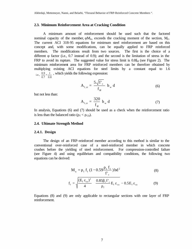
The design of an FRP-reinforced member according to this method is similar to the conventional over-reinforced case of a steel-reinforced member in which concrete crushes before the yielding of steel reinforcement. For compression-controlled failure (see Figure 4) and using equilibrium and compatibility conditions, the following two equations can be derived:
2
c
ffffn bd)
'ff
59.01(fMρ
−ρ= (8)
cufucff
c12
cuff E5.0E
'f85.04
)E(f ε−ε
ρβ
+ε
= (9)
Equations (8) and (9) are only applicable to rectangular sections with one layer of FRP reinforcement.
Alkhrdaji, Mettemeyer, Nanni, and Belarbi, “Flexural Behavior of FRP-Reinforced Concrete Members “.
8
The design can be achieved by solving Equations (8) and (9) simultaneously. For
preliminary design, the designer can use Equations (4) instead of (9) and assume an appropriate value for ff/ffu (utilizing Figure 2, say ff/ffu =0.7). In all cases, a final check should be made to ensure that the stress in FRP reinforcement at service level will not exceed the allowable stresses.
2.4.2. Analysis
In analysis, the controlling mode can be determined by comparing the reinforcement ratio, ρf, to the reinforcement ratio at the balanced strain condition, ρf,b. Two modes of failure are considered in this process: Compression failure . When ρf ≥ ρf,b. In this case, the stress in FRP reinforcement can be determined from Equation (9). The capacity is then calculated using Equation (8). Tension failure . When ρf ≤ ρf,b, the section fails by rupture of the FRP bars without crushing of concrete, which indicates that concrete did not reach its ultimate strain. Calculations are complicated because the strain in concrete at ultimate is less than 0.003 and hence, the depth of neutral axis, c, and the lever arm, jd, are unknown. In addition, the rectangular stress block factors, α1c and β1c corresponding to the concrete strain εc are also unknown. The calculations can be simplified if appropriate values are assumed for the depth of neutral axis and the lever arm. The ultimate strength of FRP under-reinforced rectangular member can be expressed as follows:
)2
cß(dfAM 1c
fdfne −= (10)
where the subscript “e” in Mne refers to the exact analysis. The parameters α1c and β1c for Whitney’s equivalent stress block corresponding to any compressive strain in concrete extreme fibers can be expressed as follows:
cco
cco1c 26
4ε−ε
ε−ε=β (11)
εcu = 0.003
c N.A.
ab =β1c 0.85 f′c ba
Af ff εf < εf,d
Af
d
Figure 4. Stress and strain distribution of FRP reinforced sections at ultimate
b
Alkhrdaji, Mettemeyer, Nanni, and Belarbi, “Flexural Behavior of FRP-Reinforced Concrete Members “.
9
2coc1
2ccco
1c3
3
εβ
ε−εε=α (12)
Equations (11) and (12) are derived based on parabolic stress-strain relationship of concrete using numerical integration. The parameter εco is the concrete strain corresponding to peak concrete stress, f’c, and is defined as follows (Todeschini, 1982):
c
cco E
f71.1 ′=ε (13)
Using compatibility requirement and knowing that the stress in FRP reinforcement will reach its ultimate design stress at failure, ffu,, the depth of neutral axis can be expressed as follows:
dcfdc
c
ε+εε
= (14)
Using equilibrium requirement and utilizing Equation (14) compatibility, the relationship between the FRP reinforcement ratio, ρf, and the strain in concrete extreme fibers, εc, can be expressed as follows:
fdc
c
fd
c1cc1f e
eff'
ß?ε+
α= (15)
Substituting Equation (14) in Equation (10) yields the following:
)2
ß(1dfAM
fdc
c1cfdfne ε+ε
ε−= (16)
In general, as the ratio of FRP reinforcement, ρf, increases the compressive strain in concrete extreme fibers, εc, at failure will increase and will reach εcu = 0.003 when ρf = ρf,b. The value of β1c, on the other hand, will decrease as εc increases. Hence the product of β1c c given in Equation (10) will remain relatively constant and can be approximated by their product at balanced strain condition given as β1 cb. Where β1 is calculated from equation (11) for εc = εcu = 0.003 or using the β1 value given in the ACI-318-95 building code. Based on this approach, the approximate ultimate capacity of under-reinforced members can be expressed as follows:
)2cß
(dfAM b1fdfna −= (17)
In which the depth of neutral axis at balanced strain condition is calculated using the following expression:
dcfdcu
cub ε+ε
ε= (18)
Substituting Equation (18) in Equation (17) yields the following:
)2ß
(1dfAMfdcu
cu1fdfna ε+ε
ε−= (19)
The ratio of Mna/Mne is then obtained by dividing Equation (19) by Equation (16) as follows:
Alkhrdaji, Mettemeyer, Nanni, and Belarbi, “Flexural Behavior of FRP-Reinforced Concrete Members “.
10
jj
2ß
1
2ß
1
MM b
fdc
c1c
fdcu
cu1
ne
na =
ε+εε
−
ε+εε
−= (20)
Where jb and j are the ratios of the lever arm to reinforcement depth, d, at balanced strain condition and at any under-reinforced case, respectively. In addition, the ratio of ρf/ρf,b is obtained by dividing Equation (15) by Equation (2) as follows:
fdc
fdcu
cu
c
11
1c1c
bf,
f
ßß
ε+εε+ε
εε
αα
=ρρ
(21)
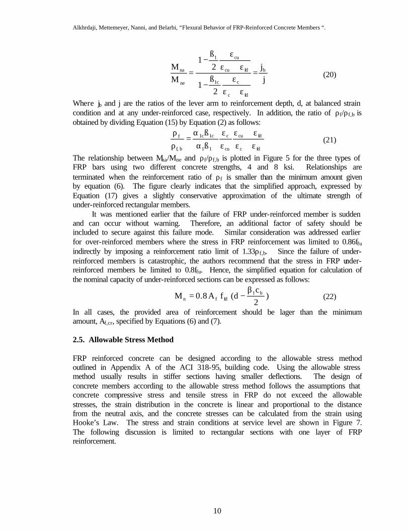
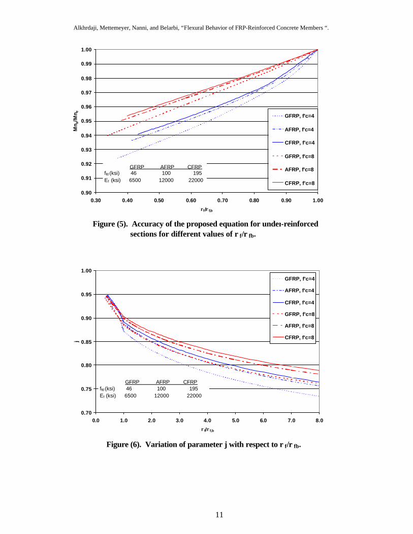
The relationship between Mna/Mne and ρf/ρf,b is plotted in Figure 5 for the three types of FRP bars using two different concrete strengths, 4 and 8 ksi. Relationships are terminated when the reinforcement ratio of ρf is smaller than the minimum amount given by equation (6). The figure clearly indicates that the simplified approach, expressed by Equation (17) gives a slightly conservative approximation of the ultimate strength of under-reinforced rectangular members. It was mentioned earlier that the failure of FRP under-reinforced member is sudden and can occur without warning. Therefore, an additional factor of safety should be included to secure against this failure mode. Similar consideration was addressed earlier for over-reinforced members where the stress in FRP reinforcement was limited to 0.86ffu indirectly by imposing a reinforcement ratio limit of 1.33ρf,b. Since the failure of under-reinforced members is catastrophic, the authors recommend that the stress in FRP under-reinforced members be limited to 0.8ffu. Hence, the simplified equation for calculation of the nominal capacity of under-reinforced sections can be expressed as follows:
)2c
d(fA8.0M b1fdfn
β−= (22)
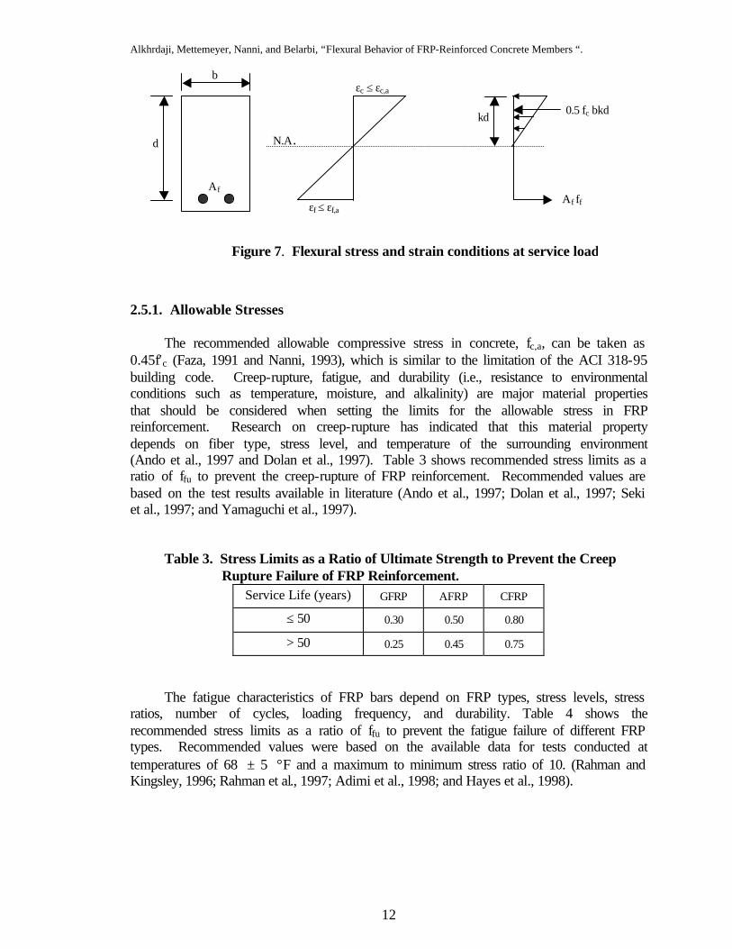
In all cases, the provided area of reinforcement should be lager than the minimum amount, Af,cr, specified by Equations (6) and (7). 2.5. Allowable Stress Method FRP reinforced concrete can be designed according to the allowable stress method outlined in Appendix A of the ACI 318-95, building code. Using the allowable stress method usually results in stiffer sections having smaller deflections. The design of concrete members according to the allowable stress method follows the assumptions that concrete compressive stress and tensile stress in FRP do not exceed the allowable stresses, the strain distribution in the concrete is linear and proportional to the distance from the neutral axis, and the concrete stresses can be calculated from the strain using Hooke’s Law. The stress and strain conditions at service level are shown in Figure 7. The following discussion is limited to rectangular sections with one layer of FRP reinforcement.
Alkhrdaji, Mettemeyer, Nanni, and Belarbi, “Flexural Behavior of FRP-Reinforced Concrete Members “.
11
Figure (5). Accuracy of the proposed equation for under-reinforced sections for different values of ρ f/ρ fb.
Figure (6). Variation of parameter j with respect to ρ f/ρ fb.
0.90
0.91
0.92
0.93
0.94
0.95
0.96
0.97
0.98
0.99
1.00
0.30 0.40 0.50 0.60 0.70 0.80 0.90 1.00
ρf/ρf,b
Mn a
/Mn e GFRP, f'c=4
AFRP, f'c=4
CFRP, f'c=4
GFRP, f'c=8
AFRP, f'c=8
CFRP, f'c=8
GFRP AFRP CFRPffd (ksi) 46 100 195 Ef (ksi) 6500 12000 22000
0.70
0.75
0.80
0.85
0.90
0.95
1.00
0.0 1.0 2.0 3.0 4.0 5.0 6.0 7.0 8.0
ρf/ρf,b
j
GFRP, f'c=4
AFRP, f'c=4
CFRP, f'c=4
GFRP, f'c=8
AFRP, f'c=8
CFRP, f'c=8
GFRP AFRP CFRPffd (ksi) 46 100 195 Ef (ksi) 6500 12000 22000
Alkhrdaji, Mettemeyer, Nanni, and Belarbi, “Flexural Behavior of FRP-Reinforced Concrete Members “.
12
2.5.1. Allowable Stresses
The recommended allowable compressive stress in concrete, fc,a, can be taken as 0.45f′c (Faza, 1991 and Nanni, 1993), which is similar to the limitation of the ACI 318-95 building code. Creep-rupture, fatigue, and durability (i.e., resistance to environmental conditions such as temperature, moisture, and alkalinity) are major material properties that should be considered when setting the limits for the allowable stress in FRP reinforcement. Research on creep-rupture has indicated that this material property depends on fiber type, stress level, and temperature of the surrounding environment (Ando et al., 1997 and Dolan et al., 1997). Table 3 shows recommended stress limits as a ratio of ffu to prevent the creep-rupture of FRP reinforcement. Recommended values are based on the test results available in literature (Ando et al., 1997; Dolan et al., 1997; Seki et al., 1997; and Yamaguchi et al., 1997).
Table 3. Stress Limits as a Ratio of Ultimate Strength to Prevent the Creep Rupture Failure of FRP Reinforcement.
Service Life (years) GFRP AFRP CFRP
≤ 50 0.30 0.50 0.80
> 50 0.25 0.45 0.75
The fatigue characteristics of FRP bars depend on FRP types, stress levels, stress
ratios, number of cycles, loading frequency, and durability. Table 4 shows the recommended stress limits as a ratio of ffu to prevent the fatigue failure of different FRP types. Recommended values were based on the available data for tests conducted at temperatures of 68 ± 5 °F and a maximum to minimum stress ratio of 10. (Rahman and Kingsley, 1996; Rahman et al., 1997; Adimi et al., 1998; and Hayes et al., 1998).
εc ≤ εc,a
N.A..
kd 0.5 fc bkd
Af ff εf ≤ εf,a
Af
d
Figure 7. Flexural stress and strain conditions at service load
b
Alkhrdaji, Mettemeyer, Nanni, and Belarbi, “Flexural Behavior of FRP-Reinforced Concrete Members “.
13
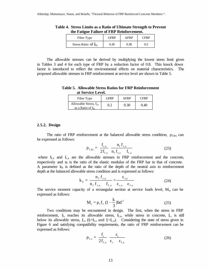
Table 4. Stress Limits as a Ratio of Ultimate Strength to Prevent the Fatigue Failure of FRP Reinforcement.
Fiber Type GFRP AFRP CFRP
Stress Ratio of ffu 0.30 0.38 0.5
The allowable stresses can be derived by multiplying the lowest stress limit given
in Tables 3 and 4 for each type of FRP by a reduction factor of 0.8. This knock down factor is introduced to reflect the environmental effects on material characteristics. The proposed allowable stresses in FRP reinforcement at service level are shown in Table 5.
Table 5. Allowable Stress Ratios for FRP Reinforcement at Service Level. Fiber Type GFRP AFRP CFRP
Allowable Stress, ff,a as a Ratio of ffu
0.2 0.30 0.40
2.5.2. Design
The ratio of FRP reinforcement at the balanced allowable stress condition, ρf,bs, can be expressed as follows:
a,fa,cf
a,cf
a,f
a,cbs,f ffn
fn
f2
f
+=ρ (23)
where ff,a and fc,a are the allowable stresses in FRP reinforcement and the concrete, respectively and nf is the ratio of the elastic modulus of the FRP bar to that of concrete. A parameter kb is defined as the ratio of the depth of the neutral axis to reinforcement depth at the balanced allowable stress condition and is expressed as follows:
a,fa,c
a,c
a,fa,cf
a,cfb ffn
fnk
ε+ε
ε=
+= (24)
The service moment capacity of a rectangular section at service loads level, Ms, can be expressed as follows:
2ffs bd)
3k
1(fM −ρ= (25)
Two conditions may be encountered in design. The first, when the stress in FRP reinforcement, ff, reaches its allowable stress, ff,a, while stress in concrete, fc, is still below its allowable stress, fc,a (ff=ff,a and fc<fc,a). Considering the state of stress given in Figure 6 and satisfying compatibility requirements, the ratio of FRP reinforcement can be expressed as follows:
a,fc
c
a,f
cs,f f2
fε+ε
ε=ρ (26)
Alkhrdaji, Mettemeyer, Nanni, and Belarbi, “Flexural Behavior of FRP-Reinforced Concrete Members “.
14
The second condition occur when the stress in concrete, fc, reaches its allowable, fc,a, while the stress in FRP reinforcement, ff, is still below its allowable stress, ff,a (fc=fc,a and ff<ff,a). In this case, the ratio of FRP reinforcement can be expressed as follows:
fa,c
a,c
f
a,cs,f f2
f
ε+εε
=ρ (27)
Dividing Equation (26) by Equation (23) yield the following relationship:
a,c
a,f
a,c
c
a,c
a,f2
a,c
c
bs,f
s,f
ff
1
ff
ε
ε+
εε
+
=
ρρ
(28)
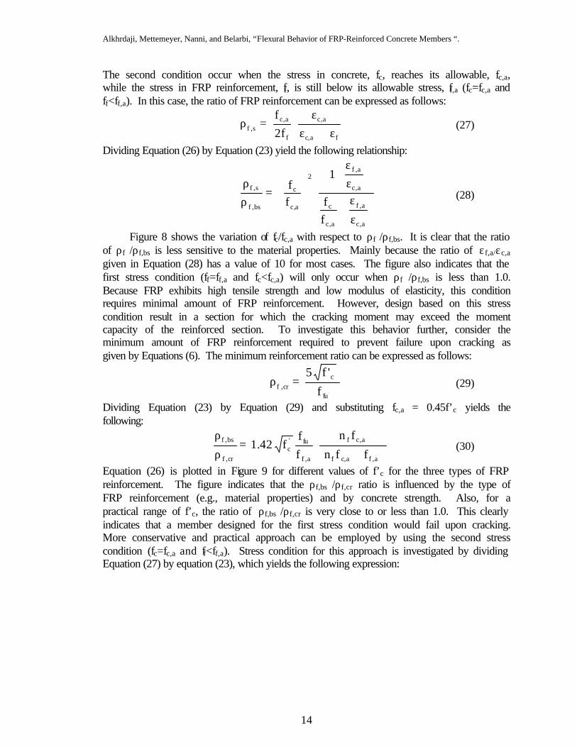
Figure 8 shows the variation of fc/fc,a with respect to ρf /ρf,bs. It is clear that the ratio of ρf /ρf,bs is less sensitive to the material properties. Mainly because the ratio of εf,a/εc,a given in Equation (28) has a value of 10 for most cases. The figure also indicates that the first stress condition (ff=ff,a and fc<fc,a) will only occur when ρf /ρf,bs is less than 1.0. Because FRP exhibits high tensile strength and low modulus of elasticity, this condition requires minimal amount of FRP reinforcement. However, design based on this stress condition result in a section for which the cracking moment may exceed the moment capacity of the reinforced section. To investigate this behavior further, consider the minimum amount of FRP reinforcement required to prevent failure upon cracking as given by Equations (6). The minimum reinforcement ratio can be expressed as follows:
fu
ccr,f f
'f5=ρ (29)
Dividing Equation (23) by Equation (29) and substituting fc,a = 0.45f’c yields the following:
a,fa,cf
a,cf
a,f
fu'c
cr,f
bs,f
ffn
fn
ff
f42.1+
=ρ
ρ (30)
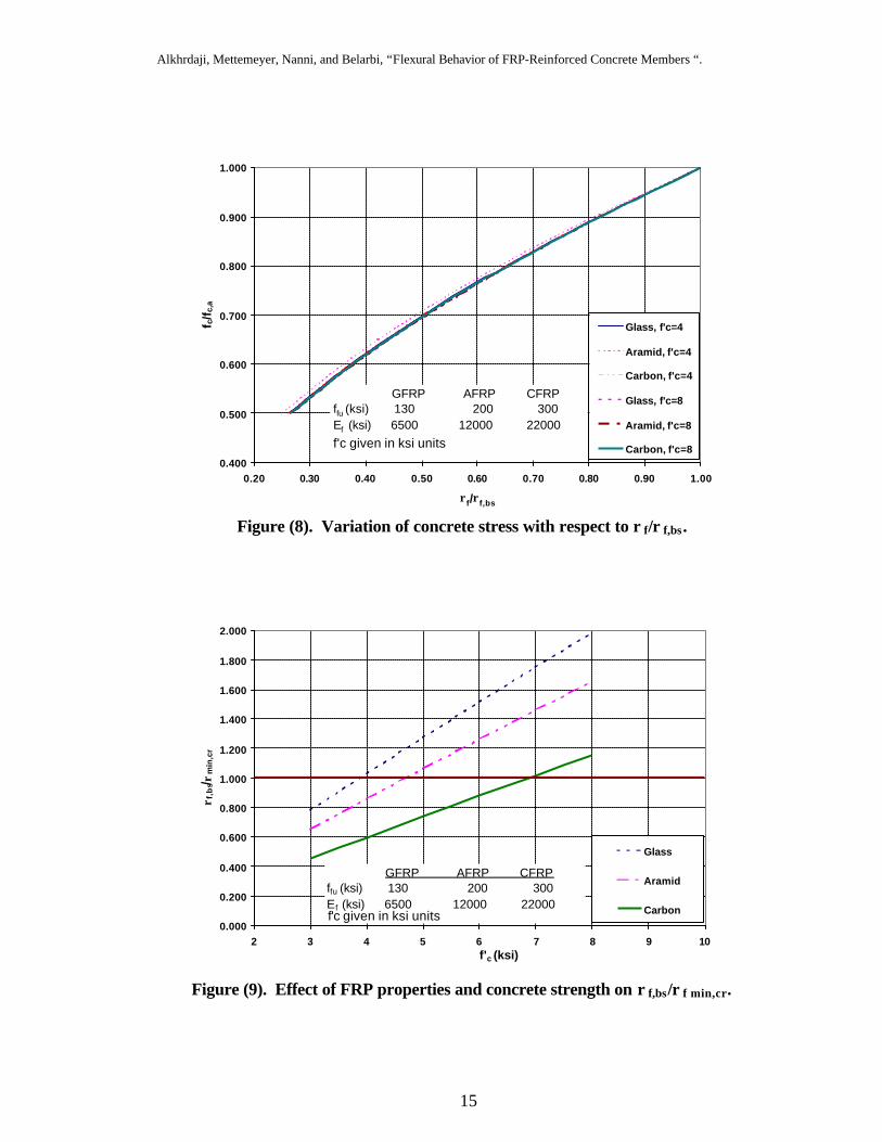
Equation (26) is plotted in Figure 9 for different values of f’c for the three types of FRP reinforcement. The figure indicates that the ρf,bs /ρf,cr ratio is influenced by the type of FRP reinforcement (e.g., material properties) and by concrete strength. Also, for a practical range of f’c, the ratio of ρf,bs /ρf,cr is very close to or less than 1.0. This clearly indicates that a member designed for the first stress condition would fail upon cracking. More conservative and practical approach can be employed by using the second stress condition (fc=fc,a and ff<ff,a). Stress condition for this approach is investigated by dividing Equation (27) by equation (23), which yields the following expression:
Alkhrdaji, Mettemeyer, Nanni, and Belarbi, “Flexural Behavior of FRP-Reinforced Concrete Members “.
15
Figure (9). Effect of FRP properties and concrete strength on ρ f,bs/ρ f min,cr.
0.000
0.200
0.400
0.600
0.800
1.000
1.200
1.400
1.600
1.800
2.000
2 3 4 5 6 7 8 9 10f'c (ksi)
ρ f,b
s/ ρm
in,c
r
Glass
Aramid
Carbon
GFRP AFRP CFRPffu (ksi) 130 200 300 Ef (ksi) 6500 12000 22000f'c given in ksi units
Figure (8). Variation of concrete stress with respect to ρ f/ρ f,bs.
0.400
0.500
0.600
0.700
0.800
0.900
1.000
0.20 0.30 0.40 0.50 0.60 0.70 0.80 0.90 1.00
ρf/ρf,bs
f c/f
c,a
Glass, f'c=4
Aramid, f'c=4
Carbon, f'c=4
Glass, f'c=8
Aramid, f'c=8
Carbon, f'c=8
GFRP AFRP CFRPffu (ksi) 130 200 300 Ef (ksi) 6500 12000 22000f'c given in ksi units
Alkhrdaji, Mettemeyer, Nanni, and Belarbi, “Flexural Behavior of FRP-Reinforced Concrete Members “.
16
a,f
a,c
a,f
f
a,f
a,c
f
a,f
bs,f
s,f
ff
1
f
f
ε
ε+
ε
ε+
=ρ
ρ (31)
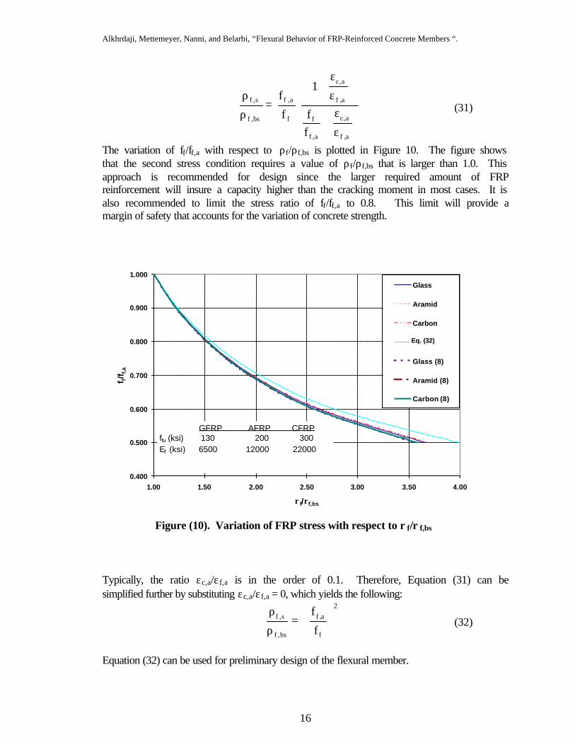
The variation of ff/ff,a with respect to ρf/ρf,bs is plotted in Figure 10. The figure shows that the second stress condition requires a value of ρf/ρf,bs that is larger than 1.0. This approach is recommended for design since the larger required amount of FRP reinforcement will insure a capacity higher than the cracking moment in most cases. It is also recommended to limit the stress ratio of ff/ff,a to 0.8. This limit will provide a margin of safety that accounts for the variation of concrete strength. Typically, the ratio εc,a/εf,a is in the order of 0.1. Therefore, Equation (31) can be simplified further by substituting εc,a/εf,a = 0, which yields the following:
2
f
a,f
bs,f
s,f
f
f
=
ρ
ρ (32)
Equation (32) can be used for preliminary design of the flexural member.
Figure (10). Variation of FRP stress with respect to ρ f/ρ f,bs
0.400
0.500
0.600
0.700
0.800
0.900
1.000
1.00 1.50 2.00 2.50 3.00 3.50 4.00
ρf/ρf,bs
f f/f f,
a
Glass
Aramid
Carbon
Series4
Glass (8)
Aramid (8)
Carbon (8)
Eq. (32)
GFRP AFRP CFRPffu (ksi) 130 200 300 Ef (ksi) 6500 12000 22000
Alkhrdaji, Mettemeyer, Nanni, and Belarbi, “Flexural Behavior of FRP-Reinforced Concrete Members “.
17
Equation (32), which is plotted in Figure 10, overestimates the required amount of FRP reinforcement. For example, when ρf / ρf,bs is about 2.5, the equation will overestimate the required amount of FRP by about 8%.
When the cross sectional dimensions are unknown, the design is initiated by selecting an FRP type and imposing ff/ff,a ratio of 0.8 or ρf / ρf,bs ratio of 1.6. The design is achieved using equation (25) and equation (31) where the parameter k is determined as follows:
fa,c
a,c
fa,cf
a,cf
ffn
fnk
ε+ε
ε=
+= (33)
In the case where the cross sectional dimensions are given, different approach should be employed. Because FRP bars exhibit high tensile strength and small modular ratio, nf, the controlling design parameter at service level is the compressive stress in concrete. Therefore, the design solution should be obtained by assuming that fc is equal to fc,a. The nominal capacity at the service level can be expressed as follows:
)3k
1(kbdf21
M 2a,cs −= (34)
From Equation (34) the parameter k can be derived as:
2a,c
s
bdfM6
25.25.1k −−= (35)
In addition, the stresses in reinforcement and at the extreme compression fiber can be related as follows:
−
=k
k1fnf a,cff (36)
If ff is less than 0.8ff,a, then the required amount of reinforcement can be determined using the following equation:
)3k
1(df
MA
f
sf
−= (37)
On the other hand, if ff is larger than 0.8ff,a then ff should be set equal to 0.8ff,a and Equations (36) and (37) are solved simultaneously to obtain the values of k and fc. A final check should be made to ensure that Af is larger than the minimum amount required to prevent failure upon cracking. 2.5.3. Analysis
Two cases may be encountered in the analysis of concrete members according to the allowable stress method. If provided ratio of, ρf, is less than the balanced ratio at service, ρf,bs, then the stress in FRP reinforcement is equal to ff,a while the stress in concrete can be determined using Equation (28). Once the stresses in concrete and FRP are determined, the parameter k can be calculated using the following Equation:
a,fc
c
a,fcf
cf
ffnfn
kε+ε
ε=
+= (38)
Alkhrdaji, Mettemeyer, Nanni, and Belarbi, “Flexural Behavior of FRP-Reinforced Concrete Members “.
18
The capacity is then calculated using the following Equation:
)3k
1(kbdf21
M 2cs −= (39)
When the provided ρf is larger than ρf,bs, then the stress in FRP reinforcement is less than ff,a while the stress in concrete is equal to the allowable stress fc,a. In this case, the stress in FRP reinforcement is determined using Equation (32) and should not exceed 0.8ff,a, the parameter k is determined using Equation (33), and the capacity using Equation (25).
A more simplified approach can be achieved by taking the nominal moment capacity to be the smaller of the two values calculated using Equation (34) and Equation (25), for which ff =0.8ff,a. The value of k is calculated using the following expression:
ff2
ffff n)n(n2k ρ−ρ+ρ= (40)
3. FLEXURAL SERVICEABILITY
Whether the design of a flexural member is achieved using the ultimate strength method or the allowable stress method, crack widths and deflections should be checked. The current expressions and requirements of the ACI 318-95 building code for crack width and deflection need to be modified to reflect the difference between material properties of steel and FRP reinforcement. In general, serviceability requirements of crack width and deflection may become the controlling factors in the design of FRP reinforced members. Compared to steel reinforced members having the same cross sectional dimensions sand flexural capacity, larger deflections and crack widths may be expected under service loads as a result of the lower flexural rigidity of some FRP reinforcement. 3.1. Cracking
Crack widths in FRP reinforced members are expected to be larger than those in steel reinforced member. Experimental and theoretical research on crack width (Faza and GangaRao, 1993; Masmoudi et al., 1996; and Gao et al., 1998) has indicated that the well-known Gregerly-Lutz equation can be modified to give a reasonable estimate of the crack width of FRP reinforced members. The original Gregerly-Lutz equation can be expressed as follows:
3css Ad)E(076.0w εβ= (41)
where w is the crack width in units of 0.001 inch, β is the ratio of the distance from the neutral axis to the extreme tension fiber to the distance from the neutral axis to the center of tensile reinforcement, dc is the thickness of the concrete cover measured to the center of the first layer of reinforcement, and A is the effective tension area of concrete
In reality, the crack width is proportional to the strain in tensile reinforcement rather than the stress (Wang and Salmon, 1992). Hence, Equation (41) can be applied to predict the crack width of FRP reinforced flexural members if the steel strain, εs, is replaced by an equivalent FRP strain, εf = ff / Ef, which results in:
Alkhrdaji, Mettemeyer, Nanni, and Belarbi, “Flexural Behavior of FRP-Reinforced Concrete Members “.
19
3cf
f
s AdfEE
076.0w β= (42)
where ff is the stress in the FRP reinforcement given in ksi. When used with FRP deformed bars having bond strength similar to that of steel, Equation (42) can estimates crack width accurately (Faza and GangaRao, 1993). However, this equation may overestimate crack width when applied to a bar with a higher bond strength than that of steel, and underestimate crack width when applied to a bar with a lower bond strength than that of steel.
In order to make Equation (41) more generic, it is necessary to introduce another coefficient that accounts for the bond behavior between the bar and the surrounding concrete. For FRP reinforced members, crack width calculation should be as follows:
3cf
f
sb Adf
EE
k076.0w β= (43)
where kb is a bond-dependant coefficient. For steel reinforcement or FRP bars having similar bond behavior to steel, kb can be taken as 1.0. For FRP bars having inferior bond behavior, kb can be larger than 1.0, and for FRP bars having superior bond behavior, kb can be smaller than 1.0. It should be noted, however, that the value of kb may be influenced by many other factors such as bond strength, bar diameter, and bar surface condition. The parameters affecting kb are yet to be determined through experiments. Using the test results from Gao et al. (1998), the calculated values of kb for three types of GFRP rods were found to be 0.71, 1.00, and 1.83. These values indicate that bond characteristics of GFRP bars can vary from superior to inferior to that of steel and can have different values for the different products even though the same types of fibers are used. The value of kb should be provided by the manufacturer of the FRP reinforcement. Further research is needed to verify the effect of bond strength on the crack width. If kb is not known, a value of 1.3 is suggested for FRP deformed rods. 3.2. Short-Term Deflections
Branson (1977) derived an equation to express the transition from Ig to Icr. His equation was adopted by the ACI in the following format:
gcr
3
a
crg
3
a
cre II
MM
1IMM
I ≤
−+
= (44)
The ACI formula given by Equation (44) was based on the behavior of steel-reinforced beams in the elastic range. Since FRP bars have a linear behavior up to failure, they provide ideal conditions for the ACI equation (Zhao et al., 1997). Research on deflection of FRP-reinforced beams (Benmokrane et al., 1996 and Brown and Bartholomew, 1996) indicates that experimental deflection curves of simply supported beams are parallel to the theoretical curves predicted by the ACI formula.
Equation (44) may overestimate the effective moment of inertia of FRP reinforced beams (Benmokrane et al., 1996). In addition, bond characteristics of different FRP bar types also affect the deflection behavior of a member. Gao et al. (1998a) proposed a modified expression for the effective moment of as follows:
Alkhrdaji, Mettemeyer, Nanni, and Belarbi, “Flexural Behavior of FRP-Reinforced Concrete Members “.
20
gcr
3
a
crg
3
a
cre II
MM
1IMM
I ≤
−+β
= (45)
where β is a reduction coefficient estimated as follows:
+α=β 1
EE
s
f (46)
where α is the bond-dependant coefficient. According to test results of simply supported beams, the value of α for a given
GFRP bar was found to be 0.5, which is the same as that for steel bars (Gao et al. 1998a). This approach is very appropriate since it does not deviate from the ACI approach for calculating the deflection. However, an extensive research program is required to determine the values of α and β and to ensure that this approach is valid for the different types of FRP bars.
3.3. Long-Term Deflections
Available data on long-term deflections of FRP reinforced beams (Kage et al., 1995 and Brown, 1997) indicates that creep behavior in FRP-reinforced beams is similar to that of steel-reinforced concrete beams. The time-deflection curves of FRP-reinforced and steel-reinforced beams have the same shape indicating that, with proper modification, the approach used to predict the long-term deflection of steel-reinforced beams can be used for FRP reinforced beams. Tests indicate that after one year, FRP-reinforced members deflected 1.2 to 1.8 times more than steel-reinforced members, depending on the type of the FRP bar (Kage et al., 1995).
According to the ACI 318-95, Section 9.5.2.5, the additional long-term deflection due to creep and shrinkage, ∆(cp+sh), can be computed using the following equations:
susi)shcp( )(∆λ=∆ + (47)
ρ′+ξ
=λ501
(48)
where λ is a multiplier for additional long-term deflection, ξ is a time-dependant factor and (∆i)sus is the immediate deflection under sustained load.
Equation (47) can be used for the case of FRP reinforcement with slight modifications to account for the differences in concrete compressive stress levels, and lower elastic modulus and different bond characteristics of FRP bars. It was mentioned earlier that compression reinforcement is not considered in the case of FRP reinforced members (ρ´f = 0), therefore, λ is equal to ξ. Using available data (Kage et al., 1995 and Brown, 1997), the calculated ratio of ξFRP/ξsteel was found to vary from 0.46 for AFRP and GFRP to 0.53 for CFRP. Based on the above results, a conservative modification factor of 0.6 is proposed. The long-term deflection of FRP-reinforced members can therefore be expressed as follows:
( )susi)shcp( 6.0 ∆ξ=∆ + (49) where ξ is the time-dependant factor given in the ACI-318-95. Further parametric studies and experimental work are necessary to validate this approach.
Alkhrdaji, Mettemeyer, Nanni, and Belarbi, “Flexural Behavior of FRP-Reinforced Concrete Members “.
21
4. COMPARISON TO EXPERIMENTAL RESULTS
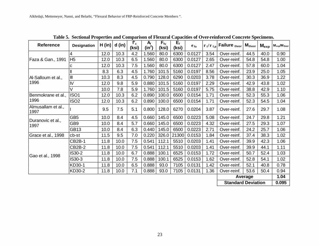
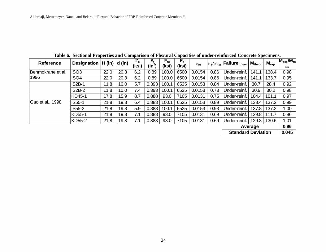
The experimental flexural strength of 29 FRP reinforced concrete beams found in the literature are compared to their theoretical values using the proposed design procedures for both over-reinforced and under-reinforced sections. Theoretical predictions were based on the actual material properties as reported by the investigators with no consideration to the proposed knockdown factor. Specimens considered for comparison have rectangular sections with one layer of tension FRP reinforcement. Of the considered specimens, 20 specimen were found to be over-reinforced and 9 were found to be under-reinforced. Description of the properties of the specimens and predicted mode of failure for the over-reinforced and under-reinforced beams are given in Tables 5 and 6, respectively. Specimens having more than one layer of tension reinforcement or compression reinforcement were excluded from this comparison.
In Tables 5, the test results for the 20 over-reinforced beams are compared to the
predicted flexural strength. The mean Mexp/Mtheo ratio is 1.04 with a standard deviation of 0.095. The test results for the 9 under-reinforced beams are compared to the predicted flexural strength in Tables 6. The mean Mexp/Mtheo ratio is 0.96 with a standard deviation of 0.045. These results show good agreement between the proposed procedure and the experimental test results of the considered specimens. Comparison of the Mexp/Mtheo ratios reveals that the proposed procedure tends to slightly under-estimate the flexural capacity of over-reinforced sections and slightly over-estimate the flexural capacity of over-reinforced sections. This behavior is related to the fact that the capacity of the over-reinforced specimens is based on the crushing of concrete at a maximum strain of 0.003. This value is relatively conservative and represents the lower bound of maximum strain attainable in concrete. On the other hand, the failure of the under-reinforced specimens is based on the experimental tensile strength of FRP reinforcement, which usually is widely variable and is calculated for a limited number of specimens. Therefore it is likely that the tensile strength of concrete embedded FRP reinforcement be lower than the value based on tests. In fact, Table 6 reveal that for almost all the considered under-reinforced members, the actual tensile strengths of FRP reinforcement were slightly lower than that those based on tensile tests. However, an FRP tensile strength based on the formula (fu-3σ) should provide more conservative results.

Alkhrdaji, Mettemeyer, Nanni, and Belarbi, “Flexural Behavior of FRP-Reinforced Concrete Members “.
23
Table 5. Sectional Properties and Comparison of Flexural Capacities of Over-reinforced Concrete Specimens.
Reference Designation H (in) d (in) f'c (ksi)
Af
(in2) Ffu
(ksi) Ef
(ksi) ε fu ρ f/ρ f,p Failure theor Mtheor Mexp Mexp/M theor
4 12.0 10.3 4.2 1.560 80.0 6300 0.0127 3.54 Over-reinf. 44.5 40.0 0.90 H5 12.0 10.3 6.5 1.560 80.0 6300 0.0127 2.65 Over-reinf. 54.8 54.8 1.00 Faza & Gan., 1991 c 12.0 10.3 7.5 1.560 80.0 6300 0.0127 2.47 Over-reinf. 57.8 60.0 1.04 II 8.3 6.3 4.5 1.760 101.5 5160 0.0197 8.56 Over-reinf. 23.9 25.0 1.05 III 10.3 8.3 4.5 0.790 128.0 6290 0.0203 3.78 Over-reinf. 30.3 36.9 1.22 IV 12.0 9.8 5.9 0.880 101.5 5160 0.0197 2.29 Over-reinf. 42.9 43.8 1.02
Al-Salloum et al., 1996
V 10.0 7.8 5.9 1.760 101.5 5160 0.0197 5.75 Over-reinf. 38.8 42.9 1.10 ISO1 12.0 10.3 6.2 0.890 100.0 6500 0.0154 1.71 Over-reinf. 52.3 55.3 1.06 Benmokrane et al.,
1996 ISO2 12.0 10.3 6.2 0.890 100.0 6500 0.0154 1.71 Over-reinf. 52.3 54.5 1.04 Almusallam et al., 1997 I 9.5 7.5 5.1 0.800 128.0 6270 0.0204 3.87 Over-reinf. 27.6 29.7 1.08
GB5 10.0 8.4 4.5 0.660 145.0 6500 0.0223 5.08 Over-reinf. 24.7 29.8 1.21 GB9 10.0 8.4 5.7 0.660 145.0 6500 0.0223 4.32 Over-reinf. 27.5 29.3 1.07
Duranovic et al., 1997
GB13 10.0 8.4 6.3 0.440 145.0 6500 0.0223 2.71 Over-reinf. 24.2 25.7 1.06 Grace et al., 1998 cb-st 11.5 9.5 7.0 0.220 326.0 21300 0.0153 1.84 Over-reinf. 37.4 38.3 1.02
CB2B-1 11.8 10.0 7.5 0.541 112.1 5510 0.0203 1.41 Over-reinf. 39.9 42.3 1.06 CB2B-2 11.8 10.0 7.5 0.541 112.1 5510 0.0203 1.41 Over-reinf. 39.9 44.1 1.11 IS30-2 11.8 10.0 6.7 0.888 100.1 6525 0.0153 1.72 Over-reinf. 50.7 52.4 1.03 IS30-3 11.8 10.0 7.5 0.888 100.1 6525 0.0153 1.62 Over-reinf. 52.8 54.1 1.02 KD30-1 11.8 10.0 6.5 0.888 93.0 7105 0.0131 1.42 Over-reinf. 52.1 40.8 0.78
Gao et al., 1998
KD30-2 11.8 10.0 7.1 0.888 93.0 7105 0.0131 1.36 Over-reinf. 53.6 50.4 0.94 Average 1.04
Standard Deviation 0.095
Alkhrdaji, Mettemeyer, Nanni, and Belarbi, “Flexural Behavior of FRP-Reinforced Concrete Members “.
24
Table 6. Sectional Properties and Comparison of Flexural Capacities of under-reinforced Concrete Specimens.
Reference Designation H (in) d (in) f'c (ksi)
Af
(in2) Ffu
(ksi) Ef
(ksi) ε fu ρ f/ρ f,p Failure theor Mtheor Mexp Mexp/Mth
eor
ISO3 22.0 20.3 6.2 0.89 100.0 6500 0.0154 0.86 Under-reinf. 141.1 138.4 0.98 Benmokrane et al, 1996 ISO4 22.0 20.3 6.2 0.89 100.0 6500 0.0154 0.86 Under-reinf. 141.1 133.7 0.95
IS2B-1 11.8 10.0 5.7 0.393 100.1 6525 0.0153 0.84 Under-reinf. 30.7 28.4 0.92 IS2B-2 11.8 10.0 7.4 0.393 100.1 6525 0.0153 0.73 Under-reinf. 30.9 30.2 0.98 KD45-1 17.8 15.9 8.7 0.888 93.0 7105 0.0131 0.75 Under-reinf. 104.4 101.1 0.97 IS55-1 21.8 19.8 6.4 0.888 100.1 6525 0.0153 0.89 Under-reinf. 138.4 137.2 0.99 IS55-2 21.8 19.8 5.9 0.888 100.1 6525 0.0153 0.93 Under-reinf. 137.8 137.2 1.00 KD55-1 21.8 19.8 7.1 0.888 93.0 7105 0.0131 0.69 Under-reinf. 129.8 111.7 0.86
Gao et al., 1998
KD55-2 21.8 19.8 7.1 0.888 93.0 7105 0.0131 0.69 Under-reinf. 129.8 130.6 1.01 Average 0.96
Standard Deviation 0.045
Alkhrdaji, Mettemeyer, Nanni, and Belarbi, “Flexural Behavior of FRP-Reinforced Concrete Members “.
25
4. CONCLUSION Design and analysis of flexural members reinforced with FRP reinforcement can be achieved using the same principal assumptions used for steel reinforced members. Design can be achieved using ultimate strength or allowable stress method. For both methods, appropriate reduction factors and stress limitations should be used to account for the variability of material properties and the unclear long-term behavior of FRP reinforcement. Design and analysis approaches addressing both methods are proposed. In the ultimate strength method, tension-controlled failure of FRP reinforced sections is not desirable since it can be more catastrophic than compression-controlled failure. After cracking, FRP reinforced members have lower stiffness than steel reinforced members with similar cross sectional dimensions and capacity. Hence, FRP reinforced members will generally have larger deflections and crack widths. Designing for a compression-controlled failure is therefore practical since it requires larger amount of FRP reinforcement resulting in stiffer members that are likely to pass serviceability requirements. Experimental results of over-reinforced and under-reinforced members in flexure are in good agreement with predicted capacities based on proposed procedures. Design based on the allowable stress method also results in stiffer sections that are compression-controlled. Design based on the allowable stress method should be such that the concrete reaches its allowable stress before the FRP reinforcement. This is because FRP exhibits high tensile strength and low modulus of elasticity. Therefore, design based on the concrete reaching its allowable stress before the FRP reinforcement results in a section minimal amount of FRP reinforcement, for which the cracking moment may exceed the moment capacity of the reinforced section. Crack width and short-term and long term deflection can be predicted using the same equations for steel reinforced members with proper modifications. Stiffness of FRP reinforcement and bond properties with concrete should be accounted for in modifying existing equations. Some of the assumptions that were made herein are yet to be proven by experiments.
Alkhrdaji, Mettemeyer, Nanni, and Belarbi, “Flexural Behavior of FRP-Reinforced Concrete Members “.
26
5. NOTATION Af = area of FRP reinforcement, in.2
Af,cr = minimum amount of FRP reinforcement needed to prevent failure of flexural members upon cracking, in.2
b = width of a rectangular cross-section, in. c = distance from extreme compression fiber to the neutral axis, in. cb = distance from extreme compression fiber to neutral axis at balanced strain condition,
in. d = distance from extreme compression fiber to centroid of tension reinforcement, in. dc = thickness of the concrete cover measured to the center of the closest layer of
longitudinal reinforcement, in. Ec = modulus of elasticity of concrete, ksi Ef = modulus of elasticity of FRP, ksi Es = modulus of elasticity of steel, ksi fc = compressive stress in concrete, ksi f′c = specified compressive strength of concrete, ksi
'cf = square root of specified compressive strength of concrete, psi
fc,a = allowable compressive stress in concrete, ksi fd = ultimate design strength of FRP reinforcement in tension, ksi ff = stress in the FRP reinforcement in tension, ksi ff,a = allowable tensile stress in FRP reinforcement, ksi ffu = ultimate strength of FRP, ksi Ie = effective moment of inertia, in.4 Ig = gross moment of inertia, in.4 k = ratio of the depth of the neutral axis to the reinforcement depth kb = ratio of the depth of the neutral axis to the reinforcement depth at balanced stress
condition kb = bond-dependant coefficient Kd = knockdown factor Mcr = cracking moment Mn = nominal moment capacity Mna = approximate nominal moment capacity of under-reinforced sections Mna = exact nominal moment capacity of under-reinforced sections Ms = moment capacity at service stress level Mu = ultimate moment based on factored loads nf = ratio of the modulus of elasticity of FRP bars to the modulus of elasticity of concrete w = crack width in units of 0.001 in. α = bond dependant coefficient used in calculation of deflection, taken as 0.5 α1 = ratio of the average stress of the equivalent rectangular stress block to f’c α1c = ratio of the average stress of the equivalent rectangular stress block to fc β = ratio of the distance from the neutral axis to the center of extreme tension fiber to the
distance from the neutral axis to the center of tensile reinforcement β = reduction coefficient used in the calculation of deflection
Alkhrdaji, Mettemeyer, Nanni, and Belarbi, “Flexural Behavior of FRP-Reinforced Concrete Members “.
27
β1 = ratio of the depth of the equivalent rectangular stress block to the depth to the neutral axis at εc = 0.003
β1c = ratio of the depth of the equivalent rectangular stress block to the depth to the neutral axis at εc
∆(cp+sh) = additional deflection due to creep and shrinkage under sustained loads, in. ∆i = immediate deflection, in. (∆i)sus = immediate deflection due to sustained loads, in. εc = strain in concrete, in./in. εc,a = strain in concrete corresponding to the allowable stress, in./in. εcu = ultimate strain of concrete, in./in. εf = strain in FRP reinforcement, in./in. εf,a = strain in FRP reinforcement corresponding to the allowable stress, in./in. εfd = ultimate design strain of FRP reinforcement, in./in. εfu = ultimate strain of FRP reinforcement, in./in. εs = strain in steel reinforcement, in./in. λ = multiplier for additional long-term deflection ξ = time-dependent factor for sustained load ρf = ratio of FRP reinforcement in tension ρf,b = ratio of FRP reinforcement producing the balanced strain condition ρf,bs = ratio of FRP reinforcement ratio producing the balanced strain condition at service
level ρf,cr = minimum ratio of FRP reinforcement needed to prevent failure of flexural
members upon cracking ρf,min = minimum ratio of FRP reinforcement required to ensure a compression failure
mode in flexural design ρf,s = ratio of FRP reinforcement in tension at service level σ = standard deviation φ = strength reduction factor
Alkhrdaji, Mettemeyer, Nanni, and Belarbi, “Flexural Behavior of FRP-Reinforced Concrete Members “.
28
6. BIBLIOGRAPHY ACI Committee 318, (1995), “Building Code Requirements for Structural Concrete (ACI 318-95) and Commentary (ACI 318R-95),” American Concrete Institute, Farmington Hills, Michigan, 369 pp. ACI Committee 440, (1996), "State-of-the-Art Report on FRP for Concrete Structures," (ACI 440R-96), Manual of Concrete Practice, American Concrete Institute, Farmington Hills, Michigan, 68 pp. Adimi, R.; Rahman, H.; Benmokrane, B.; and Kobayashi, K., (1998), “Effect of Temperature and Loading Frequency on the Fatigue Life of a CFRP Bar in Concrete,” Proceeding of the Second International Conference on Composites in Infrastructure (ICCI-98), Tucson, Arizona, Vol. 2, pp. 203-210. Almusallam, T.H.; Al-Salloum, Y.; Alsayed, S.; and Amjad, M., (1997), “Behavior of Concrete Beams Doubly Reinforced by FRP Bars,” Proceeding of the Third International Symposium on Non-Metallic (FRP) Reinforcement for Concrete Structures (FRPRCS-3), Japan Concrete Institute, Sapporo, Japan, Vol. 2, pp. 471-478. Al-Salloum,Y.; T.H.; Alsayed, S.; Almusallam, T.H.; and Amjad, M., (1996), “Evaluation of Service Load deflection For Beams reinforced by GFRP Bars,” Advancd Composite Materials in Bridges and structures (ACMBS), Canadian Society of Civil Engineering, Montreal, Quebec, pp. 165-172. Ando, N.; Matsukawa, H.; Hattori, A.; and Mashima, A., (1997), “Experimental Studies on the Long-term Tensile Properties of FRP Tendons,” Proceeding of the Third International Symposium on Non-Metallic (FRP) Reinforcement for Concrete Structures (FRPRCS-3), Japan Concrete Institute, Sapporo, Japan, Vol. 2, pp. 203-210. Benmokrane, B.; Chaallal, O.; and Masmoudi, R., (1996), “Flexural Response of Concrete Beams Reinforced with FRP Reinforcing Bars,” Structural Journal, American Concrete Institute, Vol. 93, No. 1, pp.46-55. Branson, D.E., (1977), Deformation of Concrete Structures, McGraw-Hill Book Co., New York, New York, 546 pp. Brown, V., and Bartholomew, C., (1996), “Long-term Deflections of GFRP-Reinforced Concrete Beams,” Proceeding of the First International Conference on Composites in Infrastructure (ICCI-96), Tucson, Arizona, pp. 389-400. Brown, V., (1997), “Sustained Load Deflections in GFRP-Reinforced Concrete Beams,” Proceeding of the Third International Symposium on Non-Metallic (FRP) Reinforcement for Concrete Structures (FRPRCS-3), Japan Concrete Institute, Sapporo, Japan, Vol. 2, pp. 495-502.
Alkhrdaji, Mettemeyer, Nanni, and Belarbi, “Flexural Behavior of FRP-Reinforced Concrete Members “.
29
Dolan, C.W.; Leu, B.; and Hundley, A., (1997), “Creep-Rupture of Fiber-Reinforced-Plastics in a Concrete Environment,” Proceeding of the Third International Symposium on Non-Metallic (FRP) Reinforcement for Concrete Structures (FRPRCS-3), Japan Concrete Institute, Sapporo, Japan, Vol. 2, pp. 187-194. Duranovic, N., Pilakoutas, K., and Waldron, P., (1997), “Tests on Concrete Beams Reinforced with Glass Fiber Reinforced Plastic Bars,” Proceeding of the Third International Symposium on Non-Metallic (FRP) Reinforcement for Concrete Structures (FRPRCS-3), Japan Concrete Institute, Sapporo, Japan, Vol. 2, pp. 497-486. Faza, S.S., (1991), “Bending and Bond Behavior and Design of Concrete Beams Reinforced with Fiber Reinforced Plastic Rebars,” Ph.D. Dissertation, West Virginia University, Morgentown, West Virginia, 213pp. Faza, S.S. and GangaRao, H.V.S., (1993), “Theoretical and Experimental Correlation of Behavior of Concrete Beams Reinforced with Fiber Reinforced Plastic Rebars,” Fiber-Reinforced-Plastic Reinforcement for Concrete Structures, SP-138, American Concrete Institute, Detroit, Michigan, pp. 599-614. GangaRao, H. and Vijay, P.V., (1997), “Design of Concrete Members Reinforced with GFRP Bars,” Proceeding of the Third International Symposium on Non-Metallic (FRP) Reinforcement for Concrete Structures (FRPRCS-3), Japan Concrete Institute, Sapporo, Japan, Vol. 1, pp. 143-150. Gao, D., Benmokrane, B., and Masmoudi, R., (1998), “A Calculating Method of Flexural Properties of FRP-Reinforced Concrete Beam: Part1: Crack Width and Deflection,” Technical Report, Department of Civil Engineering, University of Sherbrooke, Sherbrooke (Quebec), Canada, 24 pp. Grace, N.F., Soliman, A.K., Abdel-sayed, G., and Saleh, K.R., (1998) “Behavior and ductility of Simple and Continuous FRP Reinforced beams, ” Journal of Composites for Structures, American Society of Civil Engineers, Vol. 2, No. 4, pp. 186-194. Hayes, M.D., Garcia, K., Verghese, N., and Lesko, J., (1998), “The Effect of Moisture on the Fatigue Behavior of a Glass/Vinyl Ester Composite,” Proceeding of the Second International Conference on Composites in Infrastructure (ICCI-98), Tucson, Arizona, Vol. 1, pp. 1-12. Jaeger, L.G.; Mufti, A.; and Tadros, G., (1997), “The Concept of the Overall Performance Factor in Rectangular-Section Reinforced Concrete Beams,” Proceeding of the Third International Symposium on Non-Metallic (FRP) Reinforcement for Concrete Structures (FRPRCS-3), Japan Concrete Institute, Sapporo, Japan, Vol. 2, pp. 551-558. Japan Society of Civil Engineers (JSCE), (1997), “Recommendation for Design and Construction of Concrete Structures Using Continuous Fiber Reinforcing Materials,” Concrete Engineering Series, No. 23, 325 pp.

Alkhrdaji, Mettemeyer, Nanni, and Belarbi, “Flexural Behavior of FRP-Reinforced Concrete Members “.
30
Kage, T.; Masuda, Y.; Tanano, Y.; and Sato, K., (1995), “Long-term Deflection of Continuous Fiber Reinforced Concrete Beams,” Proceeding of the Second International RILEM Symposium on Non-Metallic (FRP) Reinforcement for Concrete Structures (FRPRCS-2), Ghent, Belgium, pp. 251-258. Kobayashi, K. and Fujisaki, T., (1995), “Compressive Behavior of FRP Reinforcement in Non-prestressed Concrete Members,” Proceeding of the Second International RILEM Symposium on Non-Metallic (FRP) Reinforcement for Concrete Structures (FRPRCS-2), Ghent, Belgium, pp. 267-274. Masmoudi, R.; Benmokrane, B.; and Challal, O., (1996), “Cracking Behavior of Concrete Beams Reinforced with FRP Rebars,” Proceeding of the First International Conference on Composites in Infrastructure (ICCI-96), Tucson, Arizona, pp. 374 – 388. Mutsuyoshi, H., Uehara, K., and Machida, A., (1990), “Mechanical Properties and Design Method of Concrete Beams Reinforced with Carbon Fiber Reinforced Plastics,” Transaction of the Japan Concrete Institute, Japan Concrete Institute, Tokyo, Japan, Vol. 12, pp. 231-238. Nanni, A., (1993), “Flexural Behavior and Design of Reinforced Concrete Using FRP Rods,” Journal of Structural Engineering, American Society of Civil Engineers, Vol. 119, No. 11, pp. 3344-3359. Rahman, A.H. and Kingsley, C.Y., (1996), “Fatigue Behavior of a Fiber-Reinforced-Plastic Grid as Reinforcement for Concrete,” Proceeding of the First International Conference on Composites in Infrastructure (ICCI-96), Tucson, Arizona, pp. 427-439. Rahman, A.H.; Adimi, R.; and Crimi, J., (1997), “Fatigue Behavior of a Carbon FRP Grid Encased in Concrete,” Proceeding of the Third International Symposium on Non-Metallic (FRP) Reinforcement for Concrete Structures (FRPRCS-3), Japan Concrete Institute, Sapporo, Japan, Vol. 2, pp. 219-226. Seki, H.; Sekijima, K.; and Konno, T., (1997), “Test Method on Creep of Continuous Fiber Reinforcing Materials,” Proceeding of the Third International Symposium on Non-Metallic (FRP) Reinforcement for Concrete Structures (FRPRCS-3), Sapporo, Japan, Vol. 2, pp. 195-202. Theriault, M., and Benmokrane, B. (1998) “Effects of FRP Reinforcement Ratio and Concrete Strength on Flexural Behavior of Concrete Beams,” American Society of Civil Engineers, Journal of Composites for Construction, Vol. 2, No.1, pp. 7-16.
Todeschini, C., Bianchini, A, and Kesler, C. (1982) “Behavior of Concrete Columns Reinforced with High Strength Steels,” ACI Journal, Proceedings, Vol. 61, No. 6, pp 701-716.
Alkhrdaji, Mettemeyer, Nanni, and Belarbi, “Flexural Behavior of FRP-Reinforced Concrete Members “.
31
Vijay, P.V. and GangaRao, H.V.S., (1996), “Unified Limit State Approach Using Deformability Factors in Concrete Beams Reinforced with GFRP Bars,” Proceedings of the Fourth Materials Engineering Conference, American Society of Civil Engineers, pp. 657-665. Wang, C.K. and Salmon, C.G., (1998), Reinforced Concrete Design, sixth Edition, Harper Collins Publication Inc., 1028 pp. Yamaguchi, T.; Kato, Y.; Nishimura, T.; and Uomoto, T., (1997), “Creep Rupture of FRP Rods Made of Aramid, Carbon and Glass Fibers,” Proceeding of the Third International Symposium on Non-Metallic (FRP) Reinforcement for Concrete Structures (FRPRCS-3), Japan Concrete Institute, Sapporo, Japan, Vol. 2, pp. 179-186. Zhao, W.; Pilakoutas, K.; and Waldron, P., (1997), “FRP Reinforced Concrete Beams: Calculations For Deflection,” Proceeding of the Third International Symposium on Non-Metallic (FRP) Reinforcement for Concrete Structures (FRPRCS-3), Japan Concrete Institute, Sapporo, Japan, Vol. 2, pp. 511-518.