Embed Size (px)
Citation preview

EGGS ON THE DOOR
CENG 491
Detailed Design Report
Duygu ÇELİK -Engin ERTAŞ – Serap İNCE
2010


1 Introduction
1.1 Problem Definition In the recent years millions all over the World have been using the Internet for different purposes. One of
the main objectives of Internet usage is communication and recently the video chat feature is the most
popularly used Internet application. Those applications not only used for business or education purposes
but also a popular tool for entertainment. In our market search we realized that people like to play online
games and video chat at the same time but a popular application which will satisfy this kind of interaction
is not present for more than two people at this moment. Which brings us to the aim of our project we plan
to create an environment that people can make video chat and play games at the same time our main goal
is to create an application which will serve for more than two people at the same time.
1.2 Purpose The purpose of preparing this document is to explain complete design details of our project Audiovisual
Gaming Network. According to the standards determined by IEEE, the Software Design Report indicates
how the proposed software system will be structured in order to satisfy the requirements identified in the
Software Requirements Specifications document. To be more explanatory, it can be stated that the
objective of this document is to translate software requirements predetermined in SRS document into a
representation of software components, interfaces and data to be used as a guide later in implementation
phase of the project.
1.3 Scope This detailed design report will mainly contain the general definition and features of the project, design
constraints, the overall system architecture and data architecture. Additionally, a brief explanation about
our current progress and schedule of the project will be provided in related sections. Design of the system
and subsystems/modules will be explained both verbally and visually by means of UML diagrams, in order
to help the programmer to understand all information stated in this document correctly and easily.
However, since every software design is open to changes and modifications, it is highly possible to make
changes during implementation and update SRS and SDD documents accordingly.
1.4 Overview Readers get a clear understanding of the project and basic design choices by examining this detailed design report. With the help of several UML diagrams, the modular architecture of the system is clearly defined in the document. Which public methods that modules have are listed in class diagrams, indicating the possible ways of interactions between modules.
1.5 Definitions and Abbreviations CLI: Command Line Interface
GUI: Graphical User Interface
MPEG: Moving Picture Experts Group
H.261 : the video coding standard of the ITU
IDR : Initial Design Report
1.6 References Westwater R., Furht B., “Real-Time Video Compression: Techniques and Algorithms.” America: Cruvel
Academic Publishers Group, 2006, np.
Ouaret M., Dufaux F., Ebrahimi T., “On Comparing Image and Video Compression Algorithms.“ Institut de
Traitement des Signaux Ecole Polytechnique Fédérale de Lausanne (EPFL), CH-1015 Lausanne,
Switzerland.
Balaško H., “Comparison of Compression Algorithms for High Definition and Super High Definition Video
Signals.” Audio Video Consulting Ltd., Karlovačka 36b, 10020 Zagreb, Croatia
Raghuveer A., Kang N., David H. C. “Techniques for Efficient Streaming of Layered
Video in Heterogeneous Client Environments.” Dept. of Computer Science & Engg. School of
Computer Science & Engg. Dept. of Computer Science & Engg , University of Minnesota Chung-Ang
University University of Minnesota Minneapolis, MN 55455 South Korea Minneapolis.
2 System Overview Our target software has three main functionalities. The first functionality is supplying communication
between any group of people whose number of members does not exceed 6. In our system, this
communication is supplied with the help of direct IP connection. In order to make this facility available, we
are going to use some libraries of C# programming language and make use of fundamental network
algorithms.
The second functionality is providing the software users with the capability of involving in audiovisual
conversation. In order to reach that aim, we consider using some streaming algorithms that are explained
further in following sections. Also, since our system’s audiovisual ability is available to 6 people, we need
to decrease the streaming size. Therefore, in order to make sampling rate considerable, we will use some
compression algorithms. Moreover, to enhance the compressed video streams, we plan to use filter
algorithms mentioned in subsequent sections of our document.
The last functionality of our software is supporting many multi-player Java games which can communicate
with the software with the help of Game Play Interface. Therefore, after the software gets in use, Java
games could be classified as “supported” and “unsupported” with respect to their abilities to connect the
main software.

In order to make a not complex design to reach these aims, we are supposed to follow a modular
approach. Namely, dividing the system into some sub-modules with regards to different functionalities not
only ease the project development steps, but also helps us to make our product reliable, efficient and
consistent.
Our project is divided into two main modules (Network and GamePlay) which are clearly explained in
“Architectural Design” part.
3 Design Considerations
3.1 Design Assumptions, Dependencies and Constraints Our project aims to entertain people in an audiovisual interactive environment. As a result, one of our
goals is to design a system that could not bother people by long response times, latencies and software
problems. Hence, system constraints are defined according to this platinum base.
Firstly, we aim to design a system which is capable of responding six people in a suitable time. We choose
not to exceed this player limit at our first version of software, since the greater the number of input
streams, the heavier the load on the network.
Secondly, each user has different bandwidth limitations. However, the total web cam streams are too big
to be received and to be sent, as 6 people are considered. Therefore, we need to reduce the amount of
data to keep the system consistent. To get over the limitation problems, we use compression algorithms in
order to handle 6 people on the system at the same time.
Thirdly, as we are multi-casting and working with the streams with different qualities, we should find a
solution which is suitable in that kind of heterogeneous inputs. To handle this problem, we used the
layered multi-casting streaming technique which serves best for our needs. Layered multi-casting
streaming divides the video into different layers by filtering, quantization and down-sampling. Then, a
basic low-quality image is sent to the receivers. On the computer of clients, with the help of filtering, the
images are decompressed. Next, according to the existing hardware and software system of the receiver,
the video is filtered and tried to be shown similar to the old quality. Using that kind of streaming
technique decreases the data load on the network. To sum up, our goal is to keep the system stable
without losing too much data during the compression and filtering processes, and keep the video in a
reasonable quality level.

3.2 Design Goals and Guidelines Our first goal of design is to implement a system that communicates a few users consistently without
synchronization problems with suitable response time and image quality. After we manage to establish
the connection between users, we are going to embed the game play module in the system. The goal of
this module is to contain an interface which will be a powerful tool to connect different kinds of games to
the system. As an external game, we will implement the taboo game (which is the default game) in our
project. The reason why we have chosen this game is that it requires visual interaction between the
players during the game. Finally, if we have time, we will try to code different games for our system.
4. Data Models and Design
Since we do not have a database in our software, we do not have any complex relations between data and
objects. In this section, we are to explain the trivial data types of our software.
4.1 Network Settings & GamePlay Settings & Preferences In our system, a user has the capability of changing some system features. This ability makes our software
much more user friendly.
These settings are going to be included in a single “settings.set” file. That file is supposed to contain each
setting on each newline.
In case of error in the setting file, default setting options are going to be chosen by our system.
4.2 Friend List In our software, each user is capable of constructing his/her friend list. According to our design, this friend
list is going to be included in “friend.xml” file. This file is going to include “Friend” objects in the system.
We do not prefer using database here, since we think that a single user on each computer could not have
more than 10000 friends. Only an index file is adequate for such a case. This index file is named as
“index.dat”. Each line of file includes information only for one “Friend” object.
The system does not allow a friend list to have more than 10000 friend objects. Moreover, in case of file
errors, the system uses the blank friend list.
4.3 Chat Diaries & Game Results A user may save her/his conversation details in external files. This ability is included in Graphical User
Interface of Network module. The details of each conversation are written to an external file whose name
is determined by the user. The external files of conservations are contained in “diary” sub-directory.
A user may save her/his game results also. Also this ability is included in GUI. The game result reports are
designed to be written by external games. However, a user must give permission to make the reports
written. The details of each game are included in an external file whose name is determined by the user.
The external files of conservations are contained in “results” sub-directory.
4.4 Extra Data Types
4.4.1 IP
As we know, a standart IP has a type like “a.b.c.d”. Here, a, b, c and d are unsigned integers ranging
between 1 and 255. Likely, our IP data type has such a structure.
IP:
unsigned int: a
unsigned int: b
unsigned int: c
unsigned int: d
4.4.2 Friend
“Friend” data type consists of three members with primitive data types:
IP: user_ip
char[20]: username
char[30]: notes
5 System Architecture
5.1 Architectural Design Our Audiovisual Gaming Software is divided into two main modules: Network and GamePlay modules.
While Network module mainly focuses on the network communications between server and clients, video
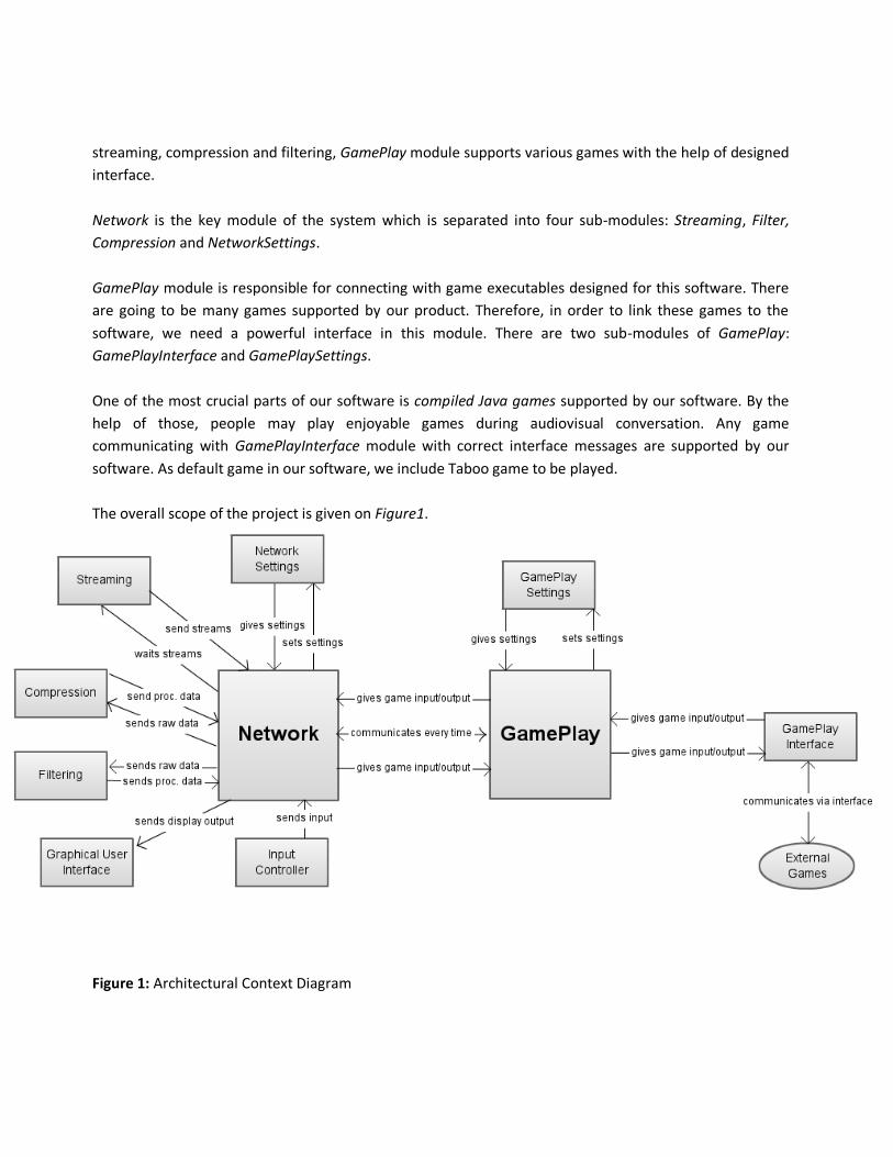
streaming, compression and filtering, GamePlay module supports various games with the help of designed
interface.
Network is the key module of the system which is separated into four sub-modules: Streaming, Filter,
Compression and NetworkSettings.
GamePlay module is responsible for connecting with game executables designed for this software. There
are going to be many games supported by our product. Therefore, in order to link these games to the
software, we need a powerful interface in this module. There are two sub-modules of GamePlay:
GamePlayInterface and GamePlaySettings.
One of the most crucial parts of our software is compiled Java games supported by our software. By the
help of those, people may play enjoyable games during audiovisual conversation. Any game
communicating with GamePlayInterface module with correct interface messages are supported by our
software. As default game in our software, we include Taboo game to be played.
The overall scope of the project is given on Figure1.
Figure 1: Architectural Context Diagram
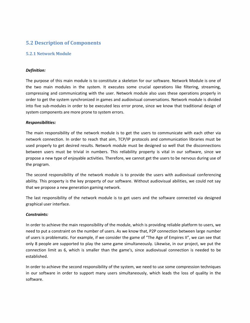
5.2 Description of Components
5.2.1 Network Module
Definition:
The purpose of this main module is to constitute a skeleton for our software. Network Module is one of
the two main modules in the system. It executes some crucial operations like filtering, streaming,
compressing and communicating with the user. Network module also uses these operations properly in
order to get the system synchronized in games and audiovisual conversations. Network module is divided
into five sub-modules in order to be executed less error prone, since we know that traditional design of
system components are more prone to system errors.
Responsibilities:
The main responsibility of the network module is to get the users to communicate with each other via
network connection. In order to reach that aim, TCP/IP protocols and communication libraries must be
used properly to get desired results. Network module must be designed so well that the disconnections
between users must be trivial in numbers. This reliability property is vital in our software, since we
propose a new type of enjoyable activities. Therefore, we cannot get the users to be nervous during use of
the program.
The second responsibility of the network module is to provide the users with audiovisual conferencing
ability. This property is the key property of our software. Without audiovisual abilities, we could not say
that we propose a new generation gaming network.
The last responsibility of the network module is to get users and the software connected via designed
graphical user interface.
Constraints:
In order to achieve the main responsibility of the module, which is providing reliable platform to users, we
need to put a constraint on the number of users. As we know that, P2P connection between large number
of users is problematic. For example, if we consider the game of “The Age of Empires II”, we can see that
only 8 people are supported to play the same game simultaneously. Likewise, in our project, we put the
connection limit as 6, which is smaller than the game's, since audiovisual connection is needed to be
established.
In order to achieve the second responsibility of the system, we need to use some compression techniques
in our software in order to support many users simultaneously, which leads the loss of quality in the
software.
Composition:
The module is divided into four sub-modules to make the software less error prone.
Uses/Interactions:
Since the network module is the main module and we consider this module as skeleton, we can think that
the network module is in interaction with the other main module GamePlay, its own sub-modules and the
users.
Resources:
This module uses mostly network resources in order to establish a communication. Also this module
requires the frequent use of CPU in order to achieve compression and filtering tasks.
Processing:
This module is not involved in direct processing of data. We consider this module as skeleton and general
interface of network sub-modules and users. The member functions are included in Section 7 of this
document.
5.2.1.1 Compression Sub-Module
Definition:
The purpose of this sub-module is to minimize the data before sending it to the remote computers. The
module produces small sized packages of data.
Responsibilities:
The main responsibility of this sub-module is to reduce the amount of data, before sending it through the
network without losing too many details. This sub-module is one of the vital pieces of the system with
regards to response/execution times of software. Namely, the load on the network the video quality, how
many people could be handled on the system is directly dependent on the compression sub-module. The
data flows through the network should be packed before being sent. All the data (images, chat data and
the data coming from the GamePlay module) is packed in this sub-module. To provide the efficient flow of
data, it is important to process the data in little time and reduce the size. Also the synchronization to be
provided and all the compressed data should be sent in correct order. In order to do this, the packages
created by the compression sub-module are numbered. The numbering system is also a safety precaution
against the failures of receiving packages. All the clients process the same numbered packages at the same
time. In case of one of the clients received the packages later than others and there are more than one
package to be processed, it processes the data which is being processed by the other clients, which
provides the system with synchronization, even if there are some latencies or faults in the network.
Constraints:
The compression sub-module is directly related to the compression algorithms. The main constraint of the
sub-module is the compression ratio. The compression ratio is the ratio that we will minimize our data
accordingly. In this system, two algorithms will be used which are namely MPEG and H 261. The MPEG
format includes compressing the images with a ratio of 30:1 and H 261 compresses with ratio 50:1. On the
other hand, as the system uses filters, the data amount of the images will be reduced too. Therefore, after
compression, the images will be compressed more than those ratios. The second constraint is that the
compression process should not take too much time, and the images ought to be sent in a suitable
duration. The compression algorithms work on the client sides and on their own machines, so that the
host is not loaded to compress the data coming from the clients. In case of too much latency is caused by
the processes the quality of and the size of the images may be reduced to decrease the computation time.
Composition:
This sub-module is not divided into smaller sub-modules or components it consist of a main compression
module and all the work is done in this module.
Uses/Interactions:
The compression sub-module compresses the data and produces packages of compressed data. Before
the compression module process the image data is passed from filtering sub-module to reduce the data
size by means of noises and tiny details in the image. These processes can be called as the encoding period
processes. After the encoding period is finished, the encoded data is sent through the network. Then, in
the receivers’ computers, decoding part is started. The compressed image should be decompressed and a
fine quality image should be displayed on the users screen. The decompressed data is a basic quality
image because of the loss of details during the compression. In order to display the images in a finer
quality than the basic image, the images are again filtered in the receivers’ computers; therefore, the data
which comes as the streams is first processed by the compression sub-module for decoding and then, it is
sent to the filtering sub-module for further process. Those two sub-modules work in collaboration with
the compression sub-module.
Resources:
The resources used by this module are the processors used to handle the compression. Since the packaged
data is sent and it is not saved in computer, not too much memory space is required. In addition, the
encoding and decoding libraries of MPEG format and H261 format are used. During the compression, the
problems could occur on the decoding and encoding periods. Another race condition will be process speed
that may differ in the different client computers. Being aware of the heterogeneous system, we are
handling the images that flows on the network that are basic quality images not loading the processor too
much.
Processing:
There are two algorithms which can be used in the system: MPEG and H 261. The details of these
algorithms are given in section 7 of the document.
5.2.1.2 Streaming Sub-Module
Definition:
The streaming sub-module is responsible for sending and receiving data and providing the communication
of the host and the clients. The data flow on the network is done via streams. Image data, gaming module
data, chat data and also voice data are divided to streams and those streams are sent and received by the
host and the clients.
Responsibilities:
The streaming sub-module is responsible for the data flow on the network. The data which is processed by
the compression sub-module is sent to the streaming sub-module as packages after being compressed.
This sub-module provides the communication between the users by means of any kind of data that is
present in the system. The streaming module is also responsible for the synchronization of the system.
The packaged data should be sent in the correct order in order to provide sharing without too much
latency.
Constraints:
The bandwidth limitations of the network are the main constraint of the streaming sub-module. The
bandwidth limitations may change in different network systems. In our system, we plan to handle at most
6 people at same time. In accordance with bandwidth load on the system, the user number that system
handles may change due to the limit. The image quality changes with respect to the video device used in
the system. To fit the in the bandwidth limitations, images may be reduced in size before being sent or the
quality could be decreased by using some filters. However, that kind of operations brings complexity in the
process, and increases the processing time of every frame. Moreover, the quality of the images reduces
too much. To accomplish the system’s consistency before losing too much data our system may have to
handle less users in such a case.
Composition: The streaming sub-module does not have smaller sub-modules or components.
Uses/Interactions:
The streaming sub-module belongs to network module and it works in collaboration with the compression
and filtering sub-modules. Our system is a multi-layered multi-casting streaming system. The data is firstly
divided into different layers and after that all those layers are compressed by the compression sub-
module. The compressed layers are then sent to the receivers by the streaming module. Finally, in the
decoding part, in the receivers’ computers, the streams are handled by the compression and filtering
modules.
Resources:
The streams are created from the data of the chat system, gaming module, video and also the other
necessary information needed to provide system synchronization. To handle the multi-layered multi-
casting streaming, the C# streaming libraries will be used.
Processing:
The multi-layered multi casting streaming is used to send streams to more than one receiver at the same
time. In our system, the host receives all the inputs from all the clients and sends all the coming inputs to
other clients, which means that the host is the one accumulating all the data and serving it to clients. As
our system is a heterogeneous system, which means that the computer resources of every user is
different. To ensure that the system will handle the data the images, the basic quality of the images are
sent to all the users with the necessary information to increase the quality by means of difference frames
and filter information. The layers consist of this information to increase the quality one step further, if the
computation power of the system is enough to handle all the filters in time that will not disrupt the
synchronization with the other users. The details are given in section 7 of the document.
5.2.1.3 Filtering Sub-Module
Definition:
The purpose of the filtering sub-module is to reduce the size of the data produced from the videos by
using some techniques and algorithms before compression and streaming.
Responsibilities:
The filtering sub-module is responsible of reducing the noises in the video and the data amount on the
system and increasing the quality of the basic images received from sender on receivers’ computers.
Constraints:
According to the processor power and the complexity of the filtering algorithm, the process time in
filtering sub-module changes. As the system should work in real time, the complexity of the algorithms
should not be in a level to cause latencies in the system. As a result, after testing the filtering sub-module,
some of the filtering algorithms may be changed to stick to the time complexity.
Composition:
The filtering sub-module does not have any smaller sub-modules but it uses de-blocking filter, down-
sampling and quantization algorithms. The de-blocking filter is applied to blocks in decoded video to
improve visual quality and prediction performance by smoothing the sharp edges which can form between
macro blocks when block coding techniques are used. The filter aims to improve the appearance of
decoded pictures. Down-sampling could be done for every data which helps to represent the data in
smaller sizes.
Uses/Interactions:
The filtering sub-module works in corporation with the filtering and streaming sub-modules. The filters are
processed on the image before and after the compression period. In the encoding process, the data is
filtered to reduce the size and then it is sent to the compression and filtering sub-modules. In the receivers
side, the filtering module works on their own. The received data is passed from filters, after decoding is
done to increase the quality of the images.
Resources:
The filtering algorithms have mathematical computations generally, and they are done in ALU of the
processors. Therefore, the higher the computational power of the processors the faster the filtering
operations is done. As the filters process the images frame by frame, the operation does not require too
much memory use or an external database.
Processing:
The filtering sub-module uses the de-blocking filter. The details of filter and other techniques are listed in
Section 7 of the document.
5.2.1.4 Network Settings Sub-Module
Definition:
Network Settings module includes the settings for network connection between the system and remote
users.
Responsibilities:
This sub-module is responsible for applying to the system some network choices like compression detail
ratio and maximum number of users that can connect.
This sub-module has to cooperate with the other sub-modules of the network module.
Constraints:
No constraints exist.
Composition:
No sub-modules exist.
Uses/Interactions:
This sub-module is in interaction with other sub-modules of Network module, and in direct relationship
between the settings of whole main module.
Resources:
This sub-module does not need any big amount of system resources.
Processing:
This sub-module neither does nor needs any specific algorithms. Only set and get methods are defined.
Member functions are described in Section 7 of the document.
5.2.2 GamePlay Module
Definition:
This module is the one of the main modules of the system providing the software the ability of executing
many multi-user turn-based games. Therefore, this module includes a specific interface, a setting module,
many supported games and interface functions for network connections.
Responsibilities:
The main responsibility of this module is to get the system to execute many supported external Java
games. In order to reach that aim, GamePlay module consists of a fast interface having 10-12 interface
functions.
The second responsibility of this module is to get the game data transferred from external games to the
other remote computers via Network main module in order to arrange turns in turn-based games.
The last responsibility of this module is to embed downloaded games to the software, which help the
system to execute the game properly.
Constraints:
The main drawback of this interface design is that the software could not execute the Java games not
having interface commands in it. Therefore, in order to operate properly, it is a must for games to connect
to the system via designed interface.
The second drawback is that this module supports only one game to be played at the same time. If a user
does not end a game, he/she cannot start a new one.
Composition:
This main module has two sub-modules which inherits some methods of this main module.
Uses/Interactions:
The module interacts with external games via designed interface, and communicates with Network
module via member functions. All the game data must be sent to Network module in order to be
delivered.
Resources:
The module mostly uses CPU resource in order to execute the external Java games. However, the amount
that is needed is not so much. Therefore, any computer could easily execute this module's operations.
Processing:
Since the module's aim is mainly to be the part of the skeleton of software, no specific algorithms are used
directly in this module. Member functions are defined in Section 7 of this document.
5.2.2.2 GamePlaySettings Sub-Module
Definition:
GamePlaySettings module includes the settings for network connection between the system and remote
users.
Responsibilities:
This sub-module is responsible for applying game choices to the games that are to be played. There are
some game choices like sound and visual options to be considered.
Constraints:
No constraints exist.
Composition:
No sub-modules exist.
Uses/Interactions:
This sub-module is in interaction with other sub-modules of GamePlay module, and in direct relationship
between the settings of whole main module.
Resources:
This sub-module does not need any big amount of system resources.
Processing:
This sub-module neither does nor needs any specific algorithms. Only set and get methods are defined.
Member functions are described in Section 7 of the document.
5.2.2.3 GamePlayInterface Sub-Module
Definition:
GamePlayInterface module includes the interface functions that a game uses in order to communicate
with the software. By the help of this interface, the system could support many turn-based external Java
games.
Responsibilities:
The main responsibility of this sub-module is to connect external games via designed interface correctly. If
this sub-module cannot be reliable and produces some errors, the external games could not be executed
properly. Moreover sometimes, synchronization problems may occur.
Constraints:
In order to reach this interface aim, our sub-module includes basic 10-12 functions to be used by games. If
a game wants to communicate with our software, the game must use these command line functions
properly.
The second constraint of this module is that only one game can interact with the software via this
interface
Composition:
No sub-modules exist.
Uses/Interactions:
This sub-module is in interaction with other sub-modules of GamePlay module, and in direct
communication with the external Java games.
Resources:
The sub-module mostly uses CPU resources to function properly. However, no extensive use of CPU is
needed, which makes our software portable to any kind of standards of system resources.
Processing:
This module uses a standard command line parser in order to communicate. This parsing algorithm is
really simple and is not computationally complex. Which member functions and external interface
commands that the sub-module have is described in Section 7 of the document.
6 User Interface Design
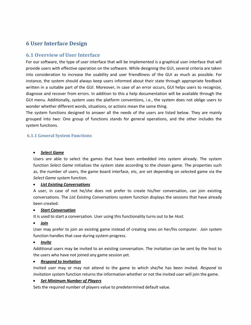
6.1 Overview of User Interface For our software, the type of user interface that will be implemented is a graphical user interface that will
provide users with effective operation on the software. While designing the GUI, several criteria are taken
into consideration to increase the usability and user friendliness of the GUI as much as possible. For
instance, the system should always keep users informed about their state through appropriate feedback
written in a suitable part of the GUI. Moreover, in case of an error occurs, GUI helps users to recognize,
diagnose and recover from errors. In addition to this a help documentation will be available through the
GUI menu. Additionally, system uses the platform conventions, i.e., the system does not oblige users to
wonder whether different words, situations, or actions mean the same thing.
The system functions designed to answer all the needs of the users are listed below. They are mainly
grouped into two: One group of functions stands for general operations, and the other includes the
system functions.
6.1.1 General System Functions
Select Game
Users are able to select the games that have been embedded into system already. The system
function Select Game initializes the system state according to the chosen game. The properties such
as, the number of users, the game board interface, etc, are set depending on selected game via the
Select Game system function.
List Existing Conversations
A user, in case of not he/she does not prefer to create his/her conversation, can join existing
conversations. The List Existing Conversations system function displays the sessions that have already
been created.
Start Conversation
It is used to start a conversation. User using this functionality turns out to be Host.
Join
User may prefer to join an existing game instead of creating ones on her/his computer. Join system
function handles that case during system progress.
Invite
Additional users may be invited to an existing conversation. The invitation can be sent by the host to
the users who have not joined any game session yet.
Respond to Invitation
Invited user may or may not attend to the game to which she/he has been invited. Respond to
Invitation system function returns the information whether or not the invited user will join the game.
Set Minimum Number of Players
Sets the required number of players value to predetermined default value.
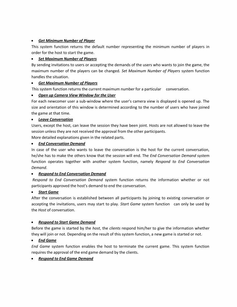
Get Minimum Number of Player
This system function returns the default number representing the minimum number of players in
order for the host to start the game.
Set Maximum Number of Players
By sending invitations to users or accepting the demands of the users who wants to join the game, the
maximum number of the players can be changed. Set Maximum Number of Players system function
handles the situation.
Get Maximum Number of Players
This system function returns the current maximum number for a particular conversation.
Open up Camera View Window for the User
For each newcomer user a sub-window where the user’s camera view is displayed is opened up. The
size and orientation of this window is determined according to the number of users who have joined
the game at that time.
Leave Conversation
Users, except the host, can leave the session they have been joint. Hosts are not allowed to leave the
session unless they are not received the approval from the other participants.
More detailed explanations given in the related parts.
End Conversation Demand
In case of the user who wants to leave the conversation is the host for the current conversation,
he/she has to make the others know that the session will end. The End Conversation Demand system
function operates together with another system function, namely Respond to End Conversation
Demand.
Respond to End Conversation Demand
Respond to End Conversation Demand system function returns the information whether or not
participants approved the host’s demand to end the conversation.
Start Game
After the conversation is established between all participants by joining to existing conversation or
accepting the invitations, users may start to play. Start Game system function can only be used by
the Host of conversation.
Respond to Start Game Demand
Before the game is started by the host, the clients respond him/her to give the information whether
they will join or not. Depending on the result of this system function, a new game is started or not.
End Game
End Game system function enables the host to terminate the current game. This system function
requires the approval of the end game demand by the clients.
Respond to End Game Demand
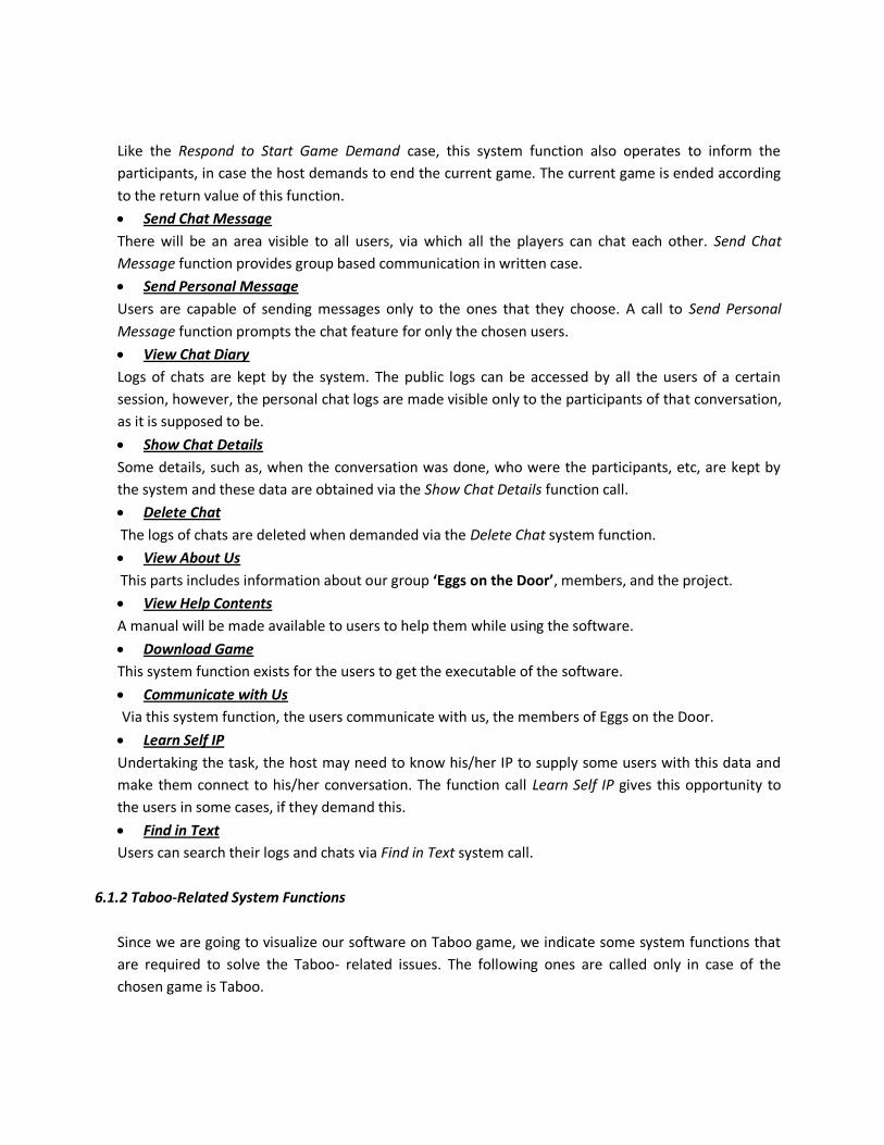
Like the Respond to Start Game Demand case, this system function also operates to inform the
participants, in case the host demands to end the current game. The current game is ended according
to the return value of this function.
Send Chat Message
There will be an area visible to all users, via which all the players can chat each other. Send Chat
Message function provides group based communication in written case.
Send Personal Message
Users are capable of sending messages only to the ones that they choose. A call to Send Personal
Message function prompts the chat feature for only the chosen users.
View Chat Diary
Logs of chats are kept by the system. The public logs can be accessed by all the users of a certain
session, however, the personal chat logs are made visible only to the participants of that conversation,
as it is supposed to be.
Show Chat Details
Some details, such as, when the conversation was done, who were the participants, etc, are kept by
the system and these data are obtained via the Show Chat Details function call.
Delete Chat
The logs of chats are deleted when demanded via the Delete Chat system function.
View About Us
This parts includes information about our group ‘Eggs on the Door’, members, and the project.
View Help Contents
A manual will be made available to users to help them while using the software.
Download Game
This system function exists for the users to get the executable of the software.
Communicate with Us
Via this system function, the users communicate with us, the members of Eggs on the Door.
Learn Self IP
Undertaking the task, the host may need to know his/her IP to supply some users with this data and
make them connect to his/her conversation. The function call Learn Self IP gives this opportunity to
the users in some cases, if they demand this.
Find in Text
Users can search their logs and chats via Find in Text system call.
6.1.2 Taboo-Related System Functions
Since we are going to visualize our software on Taboo game, we indicate some system functions that
are required to solve the Taboo- related issues. The following ones are called only in case of the
chosen game is Taboo.
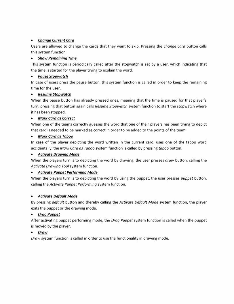
Change Current Card
Users are allowed to change the cards that they want to skip. Pressing the change card button calls
this system function.
Show Remaining Time
This system function is periodically called after the stopwatch is set by a user, which indicating that
the time is started for the player trying to explain the word.
Pause Stopwatch
In case of users press the pause button, this system function is called in order to keep the remaining
time for the user.
Resume Stopwatch
When the pause button has already pressed ones, meaning that the time is paused for that player’s
turn, pressing that button again calls Resume Stopwatch system function to start the stopwatch where
it has been stopped.
Mark Card as Correct
When one of the teams correctly guesses the word that one of their players has been trying to depict
that card is needed to be marked as correct in order to be added to the points of the team.
Mark Card as Taboo
In case of the player depicting the word written in the current card, uses one of the taboo word
accidentally, the Mark Card as Taboo system function is called by pressing taboo button.
Activate Drawing Mode
When the players turn is to depicting the word by drawing, the user presses draw button, calling the
Activate Drawing Tool system function.
Activate Puppet Performing Mode
When the players turn is to depicting the word by using the puppet, the user presses puppet button,
calling the Activate Puppet Performing system function.
Activate Default Mode
By pressing default button and thereby calling the Activate Default Mode system function, the player
exits the puppet or the drawing mode.
Drag Puppet
After activating puppet performing mode, the Drag Puppet system function is called when the puppet
is moved by the player.
Draw
Draw system function is called in order to use the functionality in drawing mode.
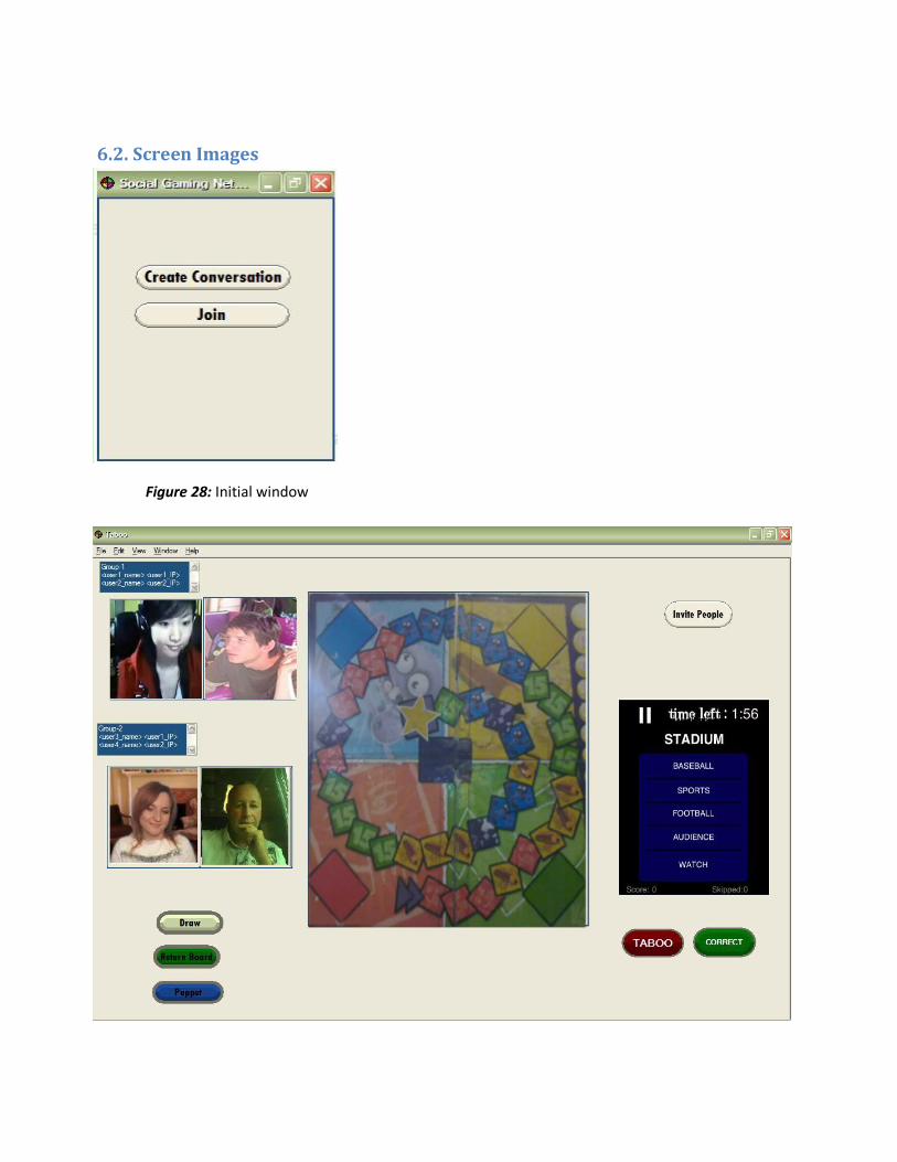
6.2. Screen Images
Figure 28: Initial window
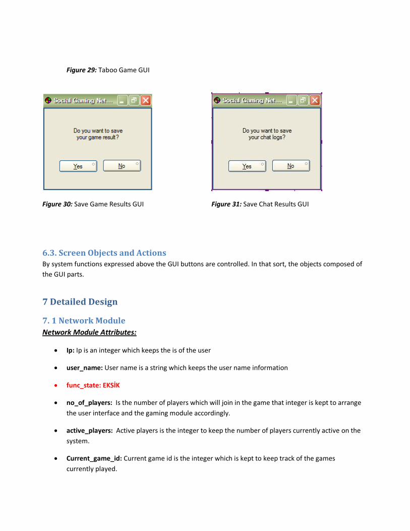
Figure 29: Taboo Game GUI
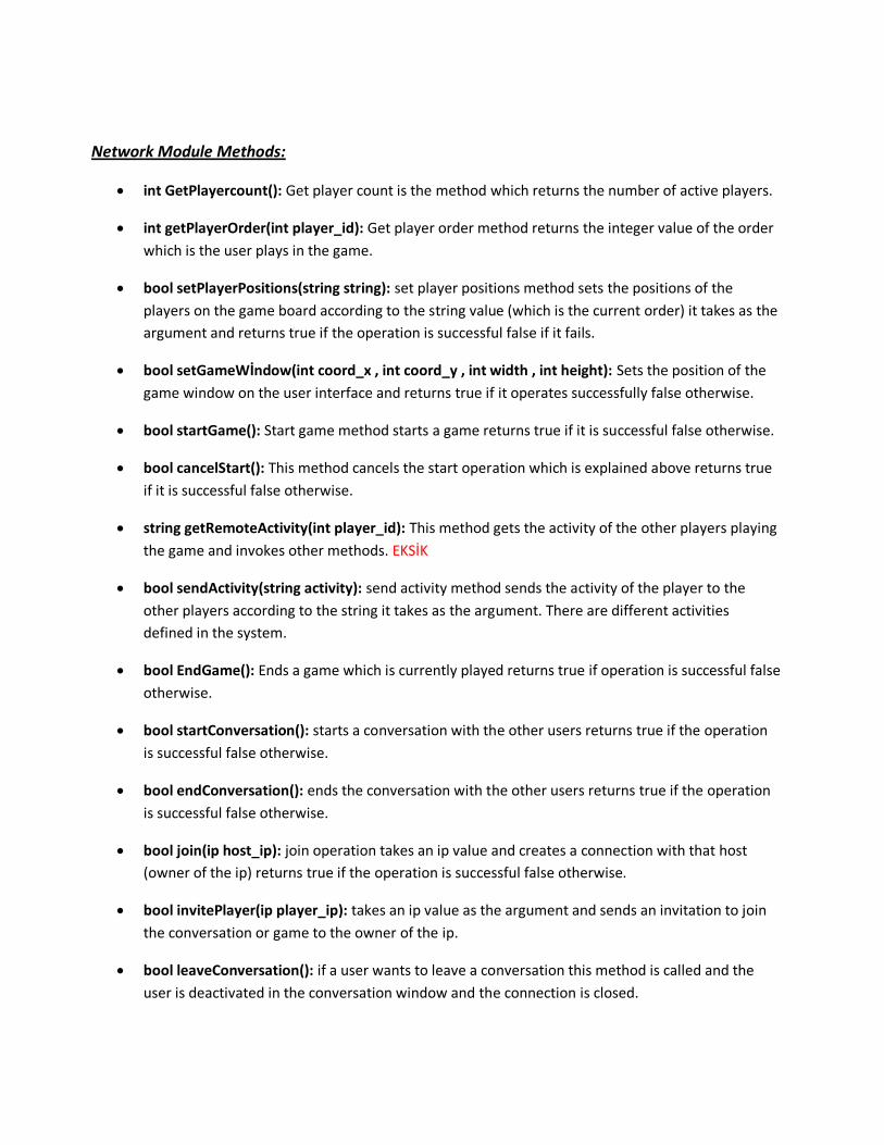
Figure 30: Save Game Results GUI Figure 31: Save Chat Results GUI
6.3. Screen Objects and Actions By system functions expressed above the GUI buttons are controlled. In that sort, the objects composed of
the GUI parts.
7 Detailed Design
7. 1 Network Module
Network Module Attributes:
Ip: Ip is an integer which keeps the is of the user
user_name: User name is a string which keeps the user name information
func_state: EKSİK
no_of_players: Is the number of players which will join in the game that integer is kept to arrange
the user interface and the gaming module accordingly.
active_players: Active players is the integer to keep the number of players currently active on the
system.
Current_game_id: Current game id is the integer which is kept to keep track of the games
currently played.
Network Module Methods:
int GetPlayercount(): Get player count is the method which returns the number of active players.
int getPlayerOrder(int player_id): Get player order method returns the integer value of the order
which is the user plays in the game.
bool setPlayerPositions(string string): set player positions method sets the positions of the
players on the game board according to the string value (which is the current order) it takes as the
argument and returns true if the operation is successful false if it fails.
bool setGameWİndow(int coord_x , int coord_y , int width , int height): Sets the position of the
game window on the user interface and returns true if it operates successfully false otherwise.
bool startGame(): Start game method starts a game returns true if it is successful false otherwise.
bool cancelStart(): This method cancels the start operation which is explained above returns true
if it is successful false otherwise.
string getRemoteActivity(int player_id): This method gets the activity of the other players playing
the game and invokes other methods. EKSİK
bool sendActivity(string activity): send activity method sends the activity of the player to the
other players according to the string it takes as the argument. There are different activities
defined in the system.
bool EndGame(): Ends a game which is currently played returns true if operation is successful false
otherwise.
bool startConversation(): starts a conversation with the other users returns true if the operation
is successful false otherwise.
bool endConversation(): ends the conversation with the other users returns true if the operation
is successful false otherwise.
bool join(ip host_ip): join operation takes an ip value and creates a connection with that host
(owner of the ip) returns true if the operation is successful false otherwise.
bool invitePlayer(ip player_ip): takes an ip value as the argument and sends an invitation to join
the conversation or game to the owner of the ip.
bool leaveConversation(): if a user wants to leave a conversation this method is called and the
user is deactivated in the conversation window and the connection is closed.
bool respondInvitation(): when an invitation is received by a host the user can choose to join or
ignore the invitation and this method is called when a user is responded to an invitation. The host
is informed by that method. This method returns true if the operation is and successful false
otherwise.
bool respondLeaveConversation(): When a user wants to leave a conversation and calls the leave
conversation method in the host side this method is called and the host responds to that action
and closes the connection with that user. This method returns true if the operation is and
successful false otherwise.
bool disableCamera(): disables the webcam. This method returns true if the operation is and
successful false otherwise.
bool EnableCamera(): enables the webcam. This method returns true if the operation is and
successful false otherwise.
bool startGame(int game_id): starts a chosen game according to the game_id. This method
returns true if the operation is and successful false otherwise.
bool respondStartGame(): respond start game is the method which is invoked when the host
called the start game method in the client sides the this method is called and the game is started if
all the users are ready to play. This method returns true if the operation is and successful false
otherwise.
bool respondEndGame(): This method is called when the host calls the end game method the
clients call that method to respond the end game action. This method returns true if the operation
is and successful false otherwise.
bool sendPM(): EKSİK This method returns true if the operation is and successful false otherwise.
bool sendChat(string message): That method gets the message to be sent as a string argument
and send it to the host after processing the message is shown on the screen. This method returns
true if the operation is and successful false otherwise.
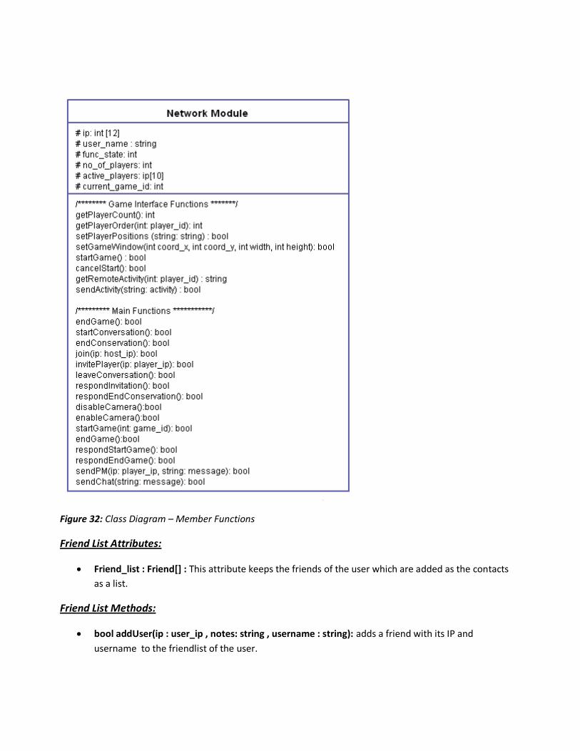
Figure 32: Class Diagram – Member Functions
Friend List Attributes:
Friend_list : Friend[] : This attribute keeps the friends of the user which are added as the contacts
as a list.
Friend List Methods:
bool addUser(ip : user_ip , notes: string , username : string): adds a friend with its IP and
username to the friendlist of the user.
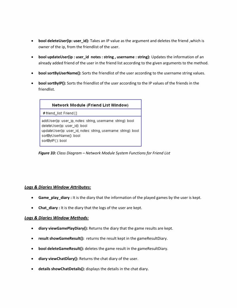
bool deleteUser(ip: user_id): Takes an IP value as the argument and deletes the friend ,which is
owner of the ip, from the friendlist of the user.
bool updateUser(ip : user_id notes : string , username : string): Updates the information of an
already added friend of the user in the friend list according to the given arguments to the method.
bool sortByUserName(): Sorts the friendlist of the user according to the username string values.
bool sortByIP(): Sorts the friendlist of the user according to the IP values of the friends in the
friendlist.
Figure 33: Class Diagram – Network Module System Functions for Friend List
Logs & Diaries Window Attributes:
Game_play_diary : It is the diary that the information of the played games by the user is kept.
Chat_diary : It is the diary that the logs of the user are kept.
Logs & Diaries Window Methods:
diary viewGamePlayDiary(): Returns the diary that the game results are kept.
result showGameResult(): returns the result kept in the gameResultDiary.
bool deleteGameResult(): deletes the game result in the gameResultDiary.
diary viewChatDİary(): Returns the chat diary of the user.
details showChatDetails(): displays the details in the chat diary.
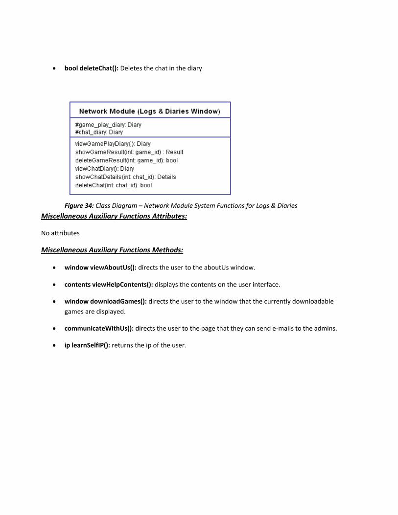
bool deleteChat(): Deletes the chat in the diary
Figure 34: Class Diagram – Network Module System Functions for Logs & Diaries
Miscellaneous Auxiliary Functions Attributes:
No attributes
Miscellaneous Auxiliary Functions Methods:
window viewAboutUs(): directs the user to the aboutUs window.
contents viewHelpContents(): displays the contents on the user interface.
window downloadGames(): directs the user to the window that the currently downloadable
games are displayed.
communicateWithUs(): directs the user to the page that they can send e-mails to the admins.
ip learnSelfIP(): returns the ip of the user.
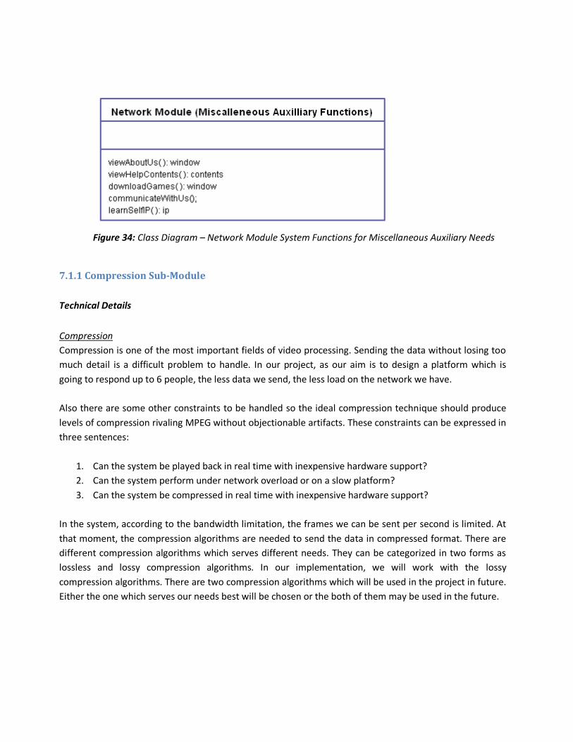
Figure 34: Class Diagram – Network Module System Functions for Miscellaneous Auxiliary Needs
7.1.1 Compression Sub-Module
Technical Details
Compression
Compression is one of the most important fields of video processing. Sending the data without losing too
much detail is a difficult problem to handle. In our project, as our aim is to design a platform which is
going to respond up to 6 people, the less data we send, the less load on the network we have.
Also there are some other constraints to be handled so the ideal compression technique should produce
levels of compression rivaling MPEG without objectionable artifacts. These constraints can be expressed in
three sentences:
1. Can the system be played back in real time with inexpensive hardware support?
2. Can the system perform under network overload or on a slow platform?
3. Can the system be compressed in real time with inexpensive hardware support?
In the system, according to the bandwidth limitation, the frames we can be sent per second is limited. At
that moment, the compression algorithms are needed to send the data in compressed format. There are
different compression algorithms which serves different needs. They can be categorized in two forms as
lossless and lossy compression algorithms. In our implementation, we will work with the lossy
compression algorithms. There are two compression algorithms which will be used in the project in future.
Either the one which serves our needs best will be chosen or the both of them may be used in the future.
MPEG
The most of the video compression algorithms takes the video and divides it into images that are not
moving and make the compression in a similar manner with the image compression algorithms. In fact, as
we are sending those images continuously on the network to more than one people, we need a better
compression algorithm. Therefore, compared to the algorithms works, in this manner MPEG compression
algorithm is more advantageous. The main advantage is that MPEG algorithm divides the image into
different segments. After that, it detects the motion in the images, which means that the segments which
do not contain any motion from beginning to the end are not sent in every frame. The motion is detected
on the segments, and the parts containing the motion and changes according to that motion are
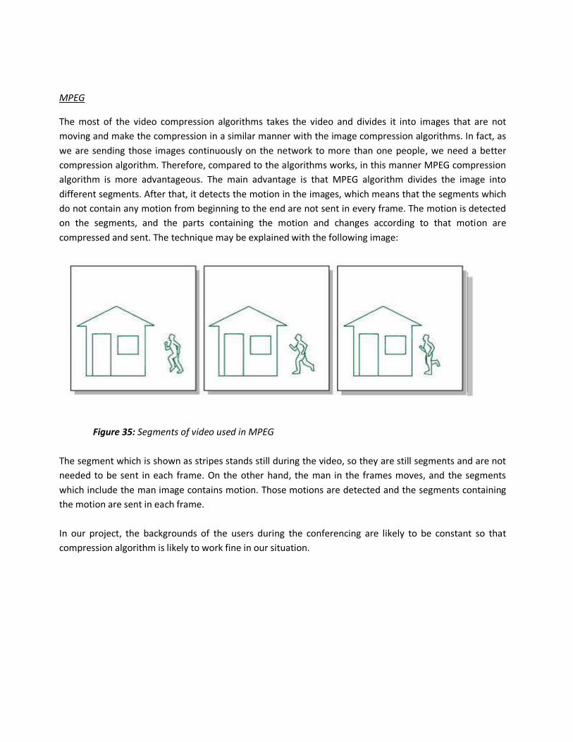
compressed and sent. The technique may be explained with the following image:
Figure 35: Segments of video used in MPEG
The segment which is shown as stripes stands still during the video, so they are still segments and are not
needed to be sent in each frame. On the other hand, the man in the frames moves, and the segments
which include the man image contains motion. Those motions are detected and the segments containing
the motion are sent in each frame.
In our project, the backgrounds of the users during the conferencing are likely to be constant so that
compression algorithm is likely to work fine in our situation.
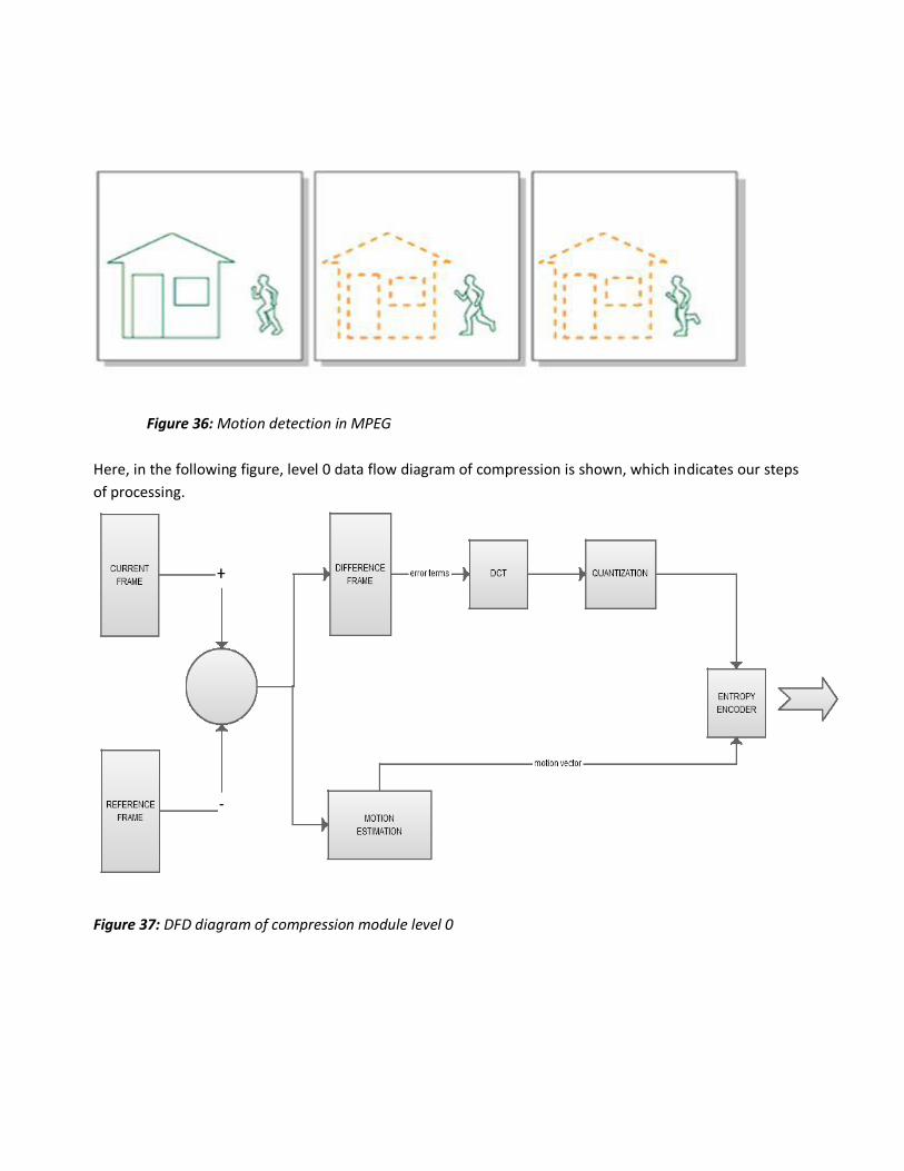
Figure 36: Motion detection in MPEG
Here, in the following figure, level 0 data flow diagram of compression is shown, which indicates our steps
of processing.
Figure 37: DFD diagram of compression module level 0

H.261 / H263
H.261 is video coding standard published by the ITU (International Telecom Union) in 1990. It was
designed for data rates which are multiples of 64Kbit/s, and is sometimes called p x 64Kbit/s (p is in the
range 1-30). These data rates suit ISDN lines, for which this video codec was designed for.
The coding algorithm is a hybrid of inter-picture prediction, transform coding and motion compensation.
The data rate of the coding algorithm was designed to be able to be set to between 40 Kbits/s and 2
Mbits/s. The inter-picture prediction removes temporal redundancy. The transform coding removes the
spatial redundancy. Motion vectors are used to help the codec compensate for motion. To remove any
further redundancy in the transmitted bit stream, variable length coding is used.
H.261 supports two resolutions, QCIF (Quarter Common Interchange format) and CIF (Common
Interchange format).
The video multiplexer structures the compressed data into a hierarchical bit stream that can be universally
interpreted. The hierarchy has four layers:
1. Picture layer: corresponds to one video picture (frame)
2. Group of blocks: corresponds to 1/12 of CIF pictures or 1/3 of QCIF
3. Macro blocks: corresponds to 16x16 pixels of luminance and the two spatially corresponding 8x8
chrominance components.
4. Blocks: corresponds to 8x8 pixels
The basic approach to H. 261 Compression is summarized as follows:
Decoded Sequence
Frame types are CCIR 601 CIF (352x288) and QCIF (176x144) images with 4:2:0 sub-sampling.
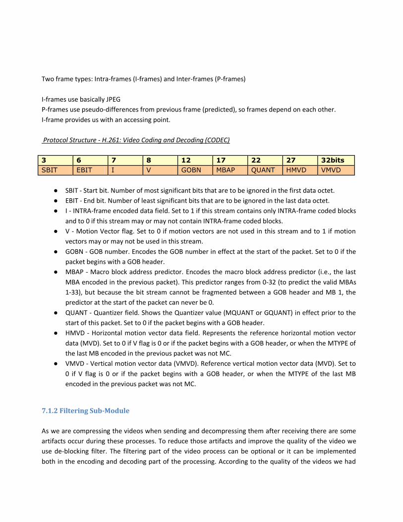
Two frame types: Intra-frames (I-frames) and Inter-frames (P-frames)
I-frames use basically JPEG
P-frames use pseudo-differences from previous frame (predicted), so frames depend on each other.
I-frame provides us with an accessing point.
Protocol Structure - H.261: Video Coding and Decoding (CODEC)
3 6 7 8 12 17 22 27 32bits
SBIT EBIT I V GOBN MBAP QUANT HMVD VMVD
● SBIT - Start bit. Number of most significant bits that are to be ignored in the first data octet.
● EBIT - End bit. Number of least significant bits that are to be ignored in the last data octet.
● I - INTRA-frame encoded data field. Set to 1 if this stream contains only INTRA-frame coded blocks
and to 0 if this stream may or may not contain INTRA-frame coded blocks.
● V - Motion Vector flag. Set to 0 if motion vectors are not used in this stream and to 1 if motion
vectors may or may not be used in this stream.
● GOBN - GOB number. Encodes the GOB number in effect at the start of the packet. Set to 0 if the
packet begins with a GOB header.
● MBAP - Macro block address predictor. Encodes the macro block address predictor (i.e., the last
MBA encoded in the previous packet). This predictor ranges from 0-32 (to predict the valid MBAs
1-33), but because the bit stream cannot be fragmented between a GOB header and MB 1, the
predictor at the start of the packet can never be 0.
● QUANT - Quantizer field. Shows the Quantizer value (MQUANT or GQUANT) in effect prior to the
start of this packet. Set to 0 if the packet begins with a GOB header.
● HMVD - Horizontal motion vector data field. Represents the reference horizontal motion vector
data (MVD). Set to 0 if V flag is 0 or if the packet begins with a GOB header, or when the MTYPE of
the last MB encoded in the previous packet was not MC.
● VMVD - Vertical motion vector data (VMVD). Reference vertical motion vector data (MVD). Set to
0 if V flag is 0 or if the packet begins with a GOB header, or when the MTYPE of the last MB
encoded in the previous packet was not MC.
7.1.2 Filtering Sub-Module
As we are compressing the videos when sending and decompressing them after receiving there are some
artifacts occur during these processes. To reduce those artifacts and improve the quality of the video we
use de-blocking filter. The filtering part of the video process can be optional or it can be implemented
both in the encoding and decoding part of the processing. According to the quality of the videos we had
and we needed in our project, we may choose to implement the filters both in the encoding and decoding
or we may just use it on the decoding part. In the implementation, we will use the de-blocking filter which
is suitable for MPEG and H261 formats.
The De-blocking Filter
The filtering sub-module uses the de-blocking filter.
A de-blocking filter is applied to blocks in decoded video to improve visual quality and prediction
performance by smoothing the sharp edges which can form between macro blocks when block coding
techniques are used. The filter aims to improve the appearance of decoded pictures.
The de-blocking filter is used both in MPEG format and H261 format. It takes part in both the encoding
and decoding process. As the filter is used in both processes, the in-loop effects of the filter is taken into
account, and the side effects could be reduced. What filter does is to de-block the data which is divided
and packed into blocks during the encoding processes. It uses reference macro-blocks for prediction.
During the encoding period, the strength of the filter can be chosen or it can be switched off completely. If
the filter is not switched off, the filter strength is chosen according to the coding modes of adjacent
blocks, quantization step size, and the steepness of the luminance gradient between blocks. There are
luma and chroma planes of each frame. The luma planes are made of the pixels which represents the
lightness and the chroma planes are made of the pixels which represents the color value of the frames.
The filter operates on both of those planes on the edges of each 4×4 or 8×8 transform block.
Two types of de-blocking are presented in following charts:
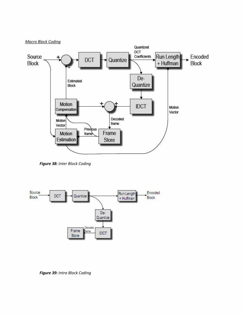
Macro Block Coding
Figure 38: Inter Block Coding
Figure 39: Intra Block Coding
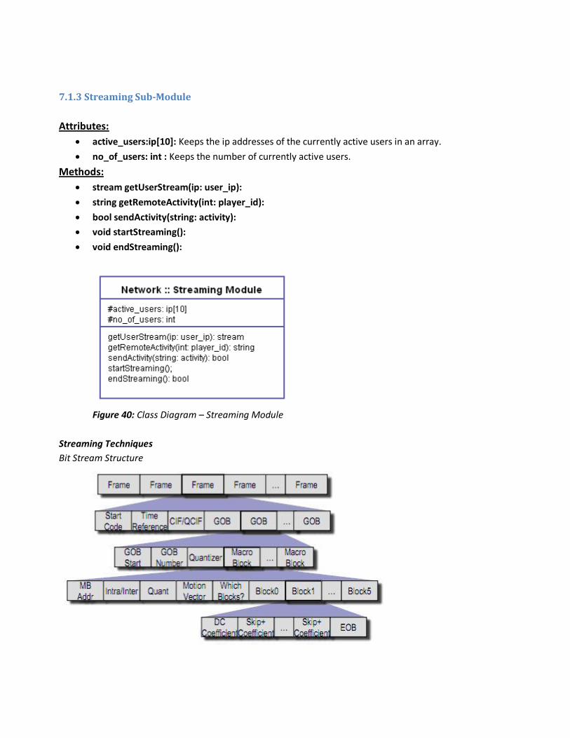
7.1.3 Streaming Sub-Module
Attributes:
active_users:ip[10]: Keeps the ip addresses of the currently active users in an array.
no_of_users: int : Keeps the number of currently active users.
Methods:
stream getUserStream(ip: user_ip):
string getRemoteActivity(int: player_id):
bool sendActivity(string: activity):
void startStreaming():
void endStreaming():
Figure 40: Class Diagram – Streaming Module
Streaming Techniques
Bit Stream Structure
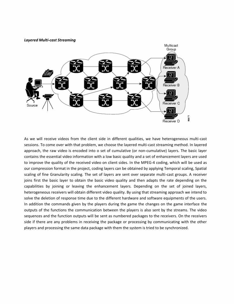
Layered Multi-cast Streaming
As we will receive videos from the client side in different qualities, we have heterogeneous multi-cast
sessions. To come over with that problem, we choose the layered multi-cast streaming method. In layered
approach, the raw video is encoded into o set of cumulative (or non-cumulative) layers. The basic layer
contains the essential video information with a low basic quality and a set of enhancement layers are used
to improve the quality of the received video on client sides. In the MPEG-4 coding, which will be used as
our compression format in the project, coding layers can be obtained by applying Temporal scaling, Spatial
scaling of fine Granularity scaling. The set of layers are sent over separate multi-cast groups. A receiver
joins first the basic layer to obtain the basic video quality and then adapts the rate depending on the
capabilities by joining or leaving the enhancement layers. Depending on the set of joined layers,
heterogeneous receivers will obtain different video quality. By using that streaming approach we intend to
solve the deletion of response time due to the different hardware and software equipments of the users.
In addition the commands given by the players during the game the changes on the game interface the
outputs of the functions the communication between the players is also sent by the streams. The video
sequences and the function outputs will be sent as numbered packages to the receivers. On the receivers
side if there are any problems in receiving the package or processing by communicating with the other
players and processing the same data package with them the system is tried to be synchronized.
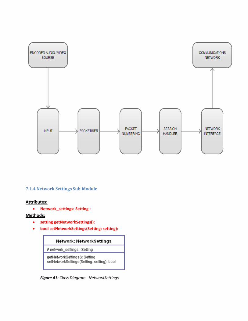
7.1.4 Network Settings Sub-Module
Attributes:
Network_settings: Setting :
Methods:
setting getNetworkSettings():
bool setNetworkSettings(Setting: setting):
Figure 41: Class Diagram –NetworkSettings
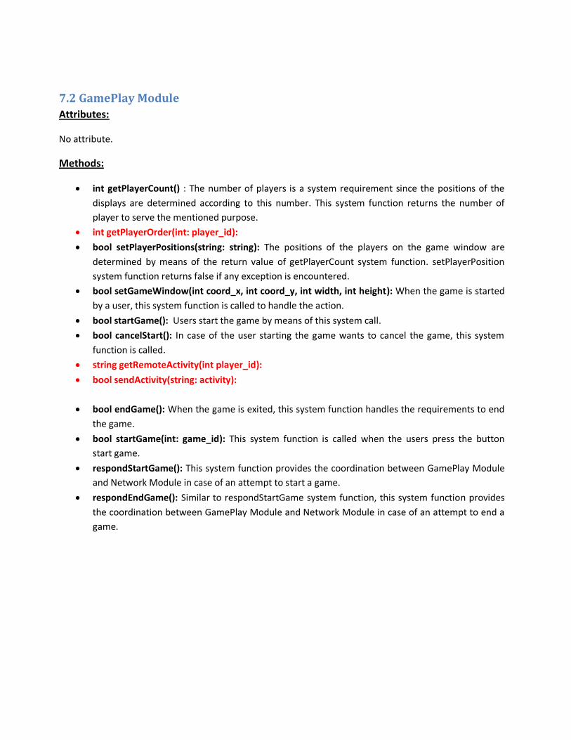
7.2 GamePlay Module
Attributes:
No attribute.
Methods:
int getPlayerCount() : The number of players is a system requirement since the positions of the
displays are determined according to this number. This system function returns the number of
player to serve the mentioned purpose.
int getPlayerOrder(int: player_id):
bool setPlayerPositions(string: string): The positions of the players on the game window are
determined by means of the return value of getPlayerCount system function. setPlayerPosition
system function returns false if any exception is encountered.
bool setGameWindow(int coord_x, int coord_y, int width, int height): When the game is started
by a user, this system function is called to handle the action.
bool startGame(): Users start the game by means of this system call.
bool cancelStart(): In case of the user starting the game wants to cancel the game, this system
function is called.
string getRemoteActivity(int player_id):
bool sendActivity(string: activity):
bool endGame(): When the game is exited, this system function handles the requirements to end
the game.
bool startGame(int: game_id): This system function is called when the users press the button
start game.
respondStartGame(): This system function provides the coordination between GamePlay Module
and Network Module in case of an attempt to start a game.
respondEndGame(): Similar to respondStartGame system function, this system function provides
the coordination between GamePlay Module and Network Module in case of an attempt to end a
game.
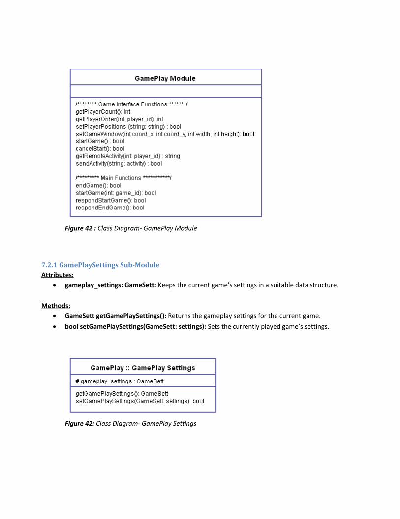
Figure 42 : Class Diagram- GamePlay Module
7.2.1 GamePlaySettings Sub-Module
Attributes:
gameplay_settings: GameSett: Keeps the current game’s settings in a suitable data structure.
Methods:
GameSett getGamePlaySettings(): Returns the gameplay settings for the current game.
bool setGamePlaySettings(GameSett: settings): Sets the currently played game’s settings.
Figure 42: Class Diagram- GamePlay Settings
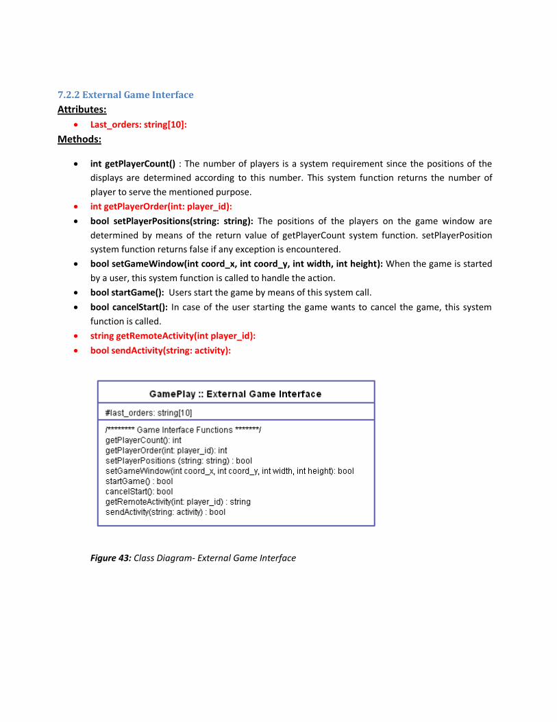
7.2.2 External Game Interface
Attributes:
Last_orders: string[10]:
Methods:
int getPlayerCount() : The number of players is a system requirement since the positions of the
displays are determined according to this number. This system function returns the number of
player to serve the mentioned purpose.
int getPlayerOrder(int: player_id):
bool setPlayerPositions(string: string): The positions of the players on the game window are
determined by means of the return value of getPlayerCount system function. setPlayerPosition
system function returns false if any exception is encountered.
bool setGameWindow(int coord_x, int coord_y, int width, int height): When the game is started
by a user, this system function is called to handle the action.
bool startGame(): Users start the game by means of this system call.
bool cancelStart(): In case of the user starting the game wants to cancel the game, this system
function is called.
string getRemoteActivity(int player_id):
bool sendActivity(string: activity):
Figure 43: Class Diagram- External Game Interface
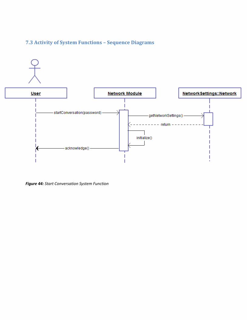
7.3 Activity of System Functions – Sequence Diagrams
Figure 44: Start Conversation System Function
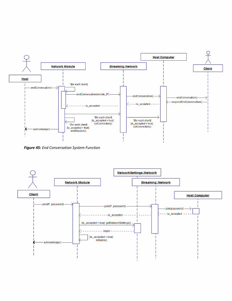
Figure 45: End Conversation System Function

Figure 46: Join System Function
Figure 47: End Session System Function
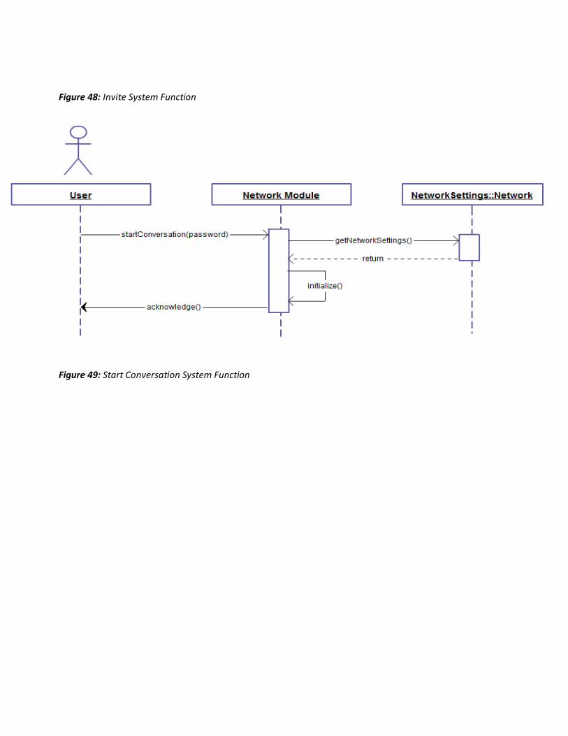
Figure 48: Invite System Function
Figure 49: Start Conversation System Function
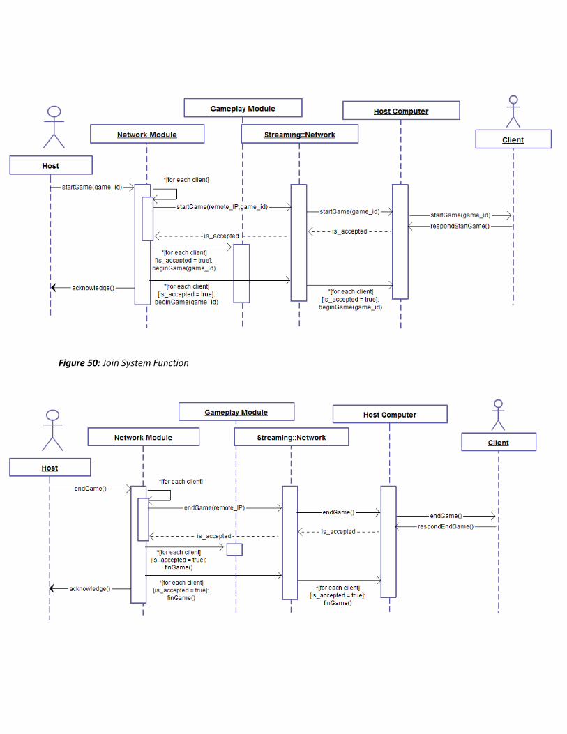
Figure 50: Join System Function
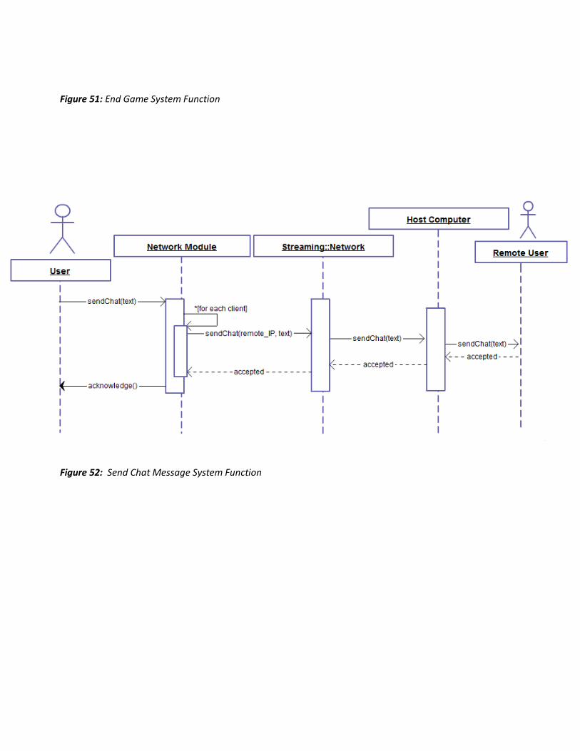
Figure 51: End Game System Function
Figure 52: Send Chat Message System Function
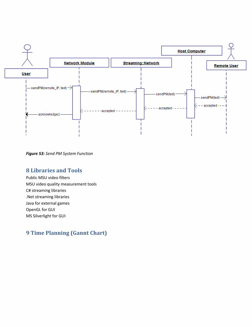
Figure 53: Send PM System Function
8 Libraries and Tools Public MSU video filters
MSU video quality measurement tools
C# streaming libraries
.Net streaming libraries
Java for external games
OpenGL for GUI
MS Silverlight for GUI
9 Time Planning (Gannt Chart)
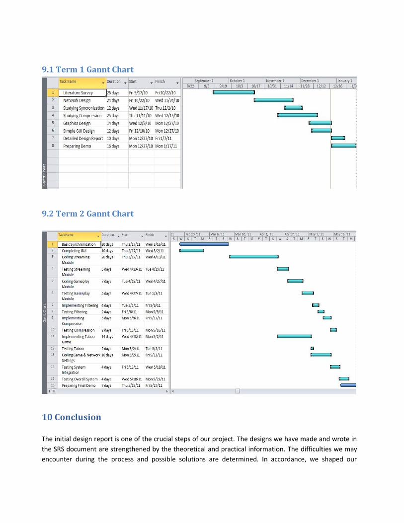
9.1 Term 1 Gannt Chart
9.2 Term 2 Gannt Chart
10 Conclusion
The initial design report is one of the crucial steps of our project. The designs we have made and wrote in
the SRS document are strengthened by the theoretical and practical information. The difficulties we may
encounter during the process and possible solutions are determined. In accordance, we shaped our

project and chosen to use technologies and algorithms which we believe to be helpful and efficient to deal
with those problems. Moreover, the IDR is like a guideline for further detailed design of our project. As we
made clear the main aspects of our project choose some algorithms and software technology to for
development of our project.
To conclude, this initial design report will be the guideline of our project this year.