Embed Size (px)
Citation preview

CEMENTITIOUS GROUTS FOR DISPOSAL OF NUCLEAR WASTEFORMS IN DEEP BOREHOLES
Nick C Collier1, Karl P Travis1, Fergus G F Gibb1, Neil B Milestone2
1 Immobilisation Science Laboratory, Department of Materials Science & Engineering, The University of Sheffield, Sheffield S1 3JD, United Kingdom, Email [email protected].
2 Callaghan Innovation, 69 Gracefield Road, PO Box 31310, Lower Hutt 5040, New Zealand.
Sealing spent nuclear fuel and high level nuclear waste in boreholes drilled several kilometers into basement rock using the Deep Borehole Disposal (DBD) process is seen as a viable alternative to emplacement in (comparatively shallow) geological repositories. Based on existing oil and geothermal well technologies, we report developments in the use of cementitious grouts as sealing/support matrices (SSMs) in the DBD process where temperatures at the waste package surface do not exceed ~190oC. Grouts based on Class G oil well cement partially replaced with silica flour are being developed, and the use of retarding admixtures investigated. Two superplasticisers have been investigated as retarders of grout thickening. A polycarboxylate admixture appears to provide sufficient retardation to be considered for use in this application and provides an increase in grout fluidity. The quantity of polycarboxylate product required to ensure fluidity for 4 hours at 90, 120 and 140°C is 0.75, 1.0 and 2.0 % by weight of cement respectively. A sulphonated admixture only appears to provide desirable retardation at 90oC. The presence of either superplasticiser does not affect composition of hardened cement paste over 14 days; the phases formed are durable under conditions of high temperature and pressure.
I. INTRODUCTION
Deep borehole disposal (DBD) of spent nuclear fuel
(SF) and high level waste (HLW) is seen as a viable alternative to emplacement in geologically shallow repositories1,2. The process is based on locating and sealing waste packages within disposal zones at the bottom of boreholes drilled several kilometers into basement rock2 and creates significant advantages over disposal in repositories a few hundred meters deep3. Building on pioneering work on deep boreholes over the past 20 years (Ref. 4, and references therein), the DBD research group at The University of Sheffield in the UK is not only developing a “rock welding” technique for borehole sealing, but is also investigating the use of cementitious grouts for sealing and supporting emplaced waste packages when temperatures at the container
surface do not exceed ~190°C2. Exposure to conditions of elevated temperature and pressure play a key role in the properties of the cementitious grout, both in the fresh state before setting, and after setting and hardening as both cause a reduction in grout thickening and setting times5, 6.
In this work we draw on knowledge from oil and geothermal well cementing applications. Grout thickening and setting time needs to be retarded to facilitate the flow of grout around the waste packages, after which the grout must set and develop sufficient compressive strength before emplacement of subsequent packages. Additionally, the grout must have wet paste properties that allow deployment through the water present in the borehole. Grouting systems based on Portland cement are being investigated in proof-of-concept studies, and a range of additives is being assessed. Rheological properties and setting characteristics of the grout are studied at elevated temperature and pressure, and early age grout composition is investigated to confirm the formation of desirable cement hydrate phases. Grout superplasticisers (also known as dispersants) are being considered because they allow a reduction in grout mix water, which will reduce permeability and improve waste package sealing. Because of the way that superplasticisers restrict chemical reaction between cement particles and mix water, retardation of grout thickening and setting can also occur. The work described here focuses on the influence of two organic superplasticisers/dispersants on grout properties.
II. EXPERIMENTAL DETAILS
Class G oil well cement7 partially replaced with silica flour was used to make the grout. The cement contained 55.11 wt% Ca3SiO5, 19.18 wt% Ca2SiO4, 1.03 wt% Ca3Al2O6 and 16.25 wt% Ca4Al2Fe2O10, and the silica flour contained 98.56 wt% SiO2. The particle diameter at 50th percentile (the D50 value) for the cement was 16.5 µm and that of the silica flour was 17.0 µm. To facilitate flow of the grout through water, an underwater/anti-washout admixture (UCS Pak) supplied by Sika Ltd was used. The superplasticisers used were Viscocrete 3110 (supplied by Sika Ltd and reported to be an aqueous
386IHLRWM 2015, Charleston, SC, April 12-16, 2015 394
solution of polycarboxylate co-polymers) and CD-33L (supplied by Baker Hughes and reported to be a sulphonated organic polymer). Tap water was used to mix the grout and grout density (excluding superplasticiser) was 1.892 kg/m3. Grout mixing was performed according to BS EN ISO 10426-1:2009 (Ref. 7).
Grout consistency was investigated using a high pressure, high temperature consistometer operating at 90, 120 and 140°C and 50 MPa with a linear 4 hour heating and pressurizing regime. For each grout that took longer than 4 hours to reach the required consistency (70 Bearden units, Bc), initial and final sets were checked 24 hours after mixing using manual Vicat testing equipment8. The progression of cement hydration reactions was investigated in an isothermal calorimeter at 120°C. Flow characteristics were investigated at ambient temperature using a modified ASTM flow cone test9 to record the time to flow through the testing cone. Although not investigated quantitatively, a degree of qualitative assessment of solid particle dispersion was investigated for each grout mix by pouring approximately 200 ml of freshly mixed grout into a 500 ml beaker of water held at 63 ± 2°C, and observing solid particle dispersion. Early age hardened grout composition was investigated by casting samples of each grout and hydrothermally curing them under water in sealed containers at 120°C for 3, 7 and 14 days. After each time interval, hydration was arrested using a solvent replacement technique10 and the
composition was investigated using X-ray diffraction (XRD) and thermogravimetric analysis/derivative thermogravimetric analysis (TGA/ DTG).
III. RESULTS AND DISCUSSION
III.A. Consistency
Grout consistency has been related to rheological
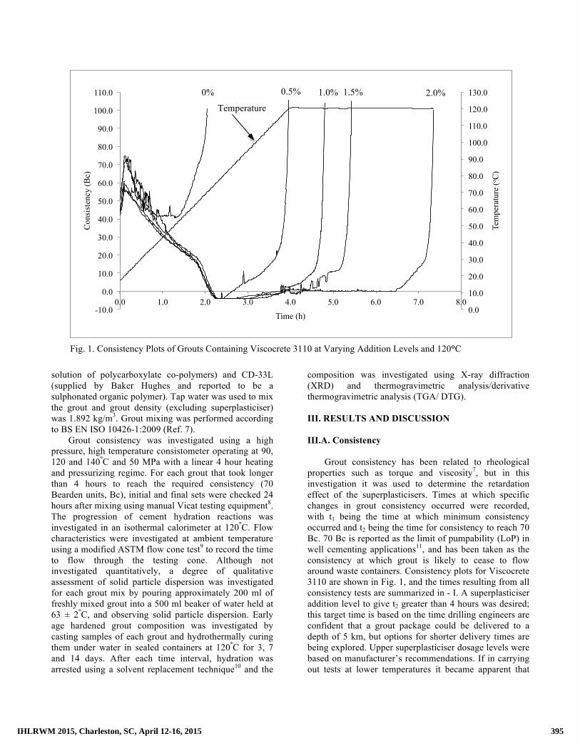
properties such as torque and viscosity7, but in this investigation it was used to determine the retardation effect of the superplasticisers. Times at which specific changes in grout consistency occurred were recorded, with t1 being the time at which minimum consistency occurred and t2 being the time for consistency to reach 70 Bc. 70 Bc is reported as the limit of pumpability (LoP) in well cementing applications11, and has been taken as the consistency at which grout is likely to cease to flow around waste containers. Consistency plots for Viscocrete 3110 are shown in Fig. 1, and the times resulting from all consistency tests are summarized in - I. A superplasticiser addition level to give t2 greater than 4 hours was desired; this target time is based on the time drilling engineers are confident that a grout package could be delivered to a depth of 5 km, but options for shorter delivery times are being explored. Upper superplasticiser dosage levels were based on manufacturer’s recommendations. If in carrying out tests at lower temperatures it became apparent that
Fig. 1. Consistency Plots of Grouts Containing Viscocrete 3110 at Varying Addition Levels and 120°C
0.0
10.0
20.0
30.0
40.0
50.0
60.0
70.0
80.0
90.0
100.0
110.0
120.0
130.0
-10.0
0.0
10.0
20.0
30.0
40.0
50.0
60.0
70.0
80.0
90.0
100.0
110.0
0.0 1.0 2.0 3.0 4.0 5.0 6.0 7.0 8.0
Tem
pera
ture
(o C)
Con
sist
ency
(Bc)
Time (h)
0% 0.5% 1.0% 1.5% 2.0% Temperature
387IHLRWM 2015, Charleston, SC, April 12-16, 2015 395

successful retardation would not be achieved at higher temperatures, then testing at the higher temperatures was not undertaken.
TABLE I. Summary of Consistency Data
Addition (% BWOC)
Consistency Data (t1, t2 (h))
90°C 120°C 140°C 0.0 1.0, 1.9 Grout Containing Viscocrete 3110 0.5 3.0, 3.6 2.2, 3.9 - 0.75 3.2, 7.1 - - 1.0 3.1, >10 2.2, 4.8 - 1.5 - 2.2, 5.4 - 2.0 - 2.2, 7.3 1.7, 4.2 3.0 - - 1.7, 5.6 Grout Containing CD-33L 0.5 - 1.4, 2.1 - 1.0 1.9, 2.7 1.7, 2.2 - 2.0 2.6, 2.9 2.2, 2.7 - 3.0 - 2.2, 2.7 - Notes: BWOC = By Weight of Cement; t1 = time at which minimum consistency occurred; t2 = time for consistency to reach 70 Bc.
The consistency of all grouts increased in the initial
stages of testing (Fig. 1). This is most likely due to the gelling effect of the organic additives. In all cases this early increase in consistency peaked after approximately 10 minutes when the temperature was between 20 and 25°C.
The change in consistency for samples containing Viscocrete 3110 was similar at all temperatures and showed a reduction in consistency after initial gelling, to an ultimate minimum value of approximately 0 Bc (using the relationship described in (Ref. 7), 0 Bc equates to 0.00782 Nm torque, which indicates a very low viscosity). Excluding the control grout, the time at which the lowest consistency was attained (t1) at each testing temperature was generally unaffected by addition level. The major influence of superplasticiser addition was on the time at which 70 Bc was reached (t2). To achieve t2 greater than 4 hours at 90, 120 and 140°C, Viscocrete 3110 addition levels of at least 0.75, 1.0 and 2.0 % by weight of cement (BWOC) respectively were required.
The consistency results for all samples containing CD-33L were more difficult to interpret. At addition levels of 2.0 and 3.0% CD-33L, the trends for all temperatures were similar to those containing Viscocrete 3110. However, the progression of consistency in samples made with CD-33L at addition levels lower than 1.0% was very similar to that of the control sample, albeit at reduced values, and the t2 times slightly increased as addition level increased. It was not possible to produce a grout containing CD-33L at 90 and 120°C where t2 > 4
hours using the addition levels studied here, so no testing was performed at 140°C.
All grouts where t2 was greater than 4 hours achieved initial and final set by 24 hours.
III.B. Calorimetry
Calorimetry curves for grouts containing Viscocrete 3110 are shown in Fig. 2 and all heat flow events are summarized in Table II.
Because samples were mixed external to the calorimeter, heat flow events that occurred before the samples reached equilibrium temperature (approximately 1 hour) were not recorded.
TABLE II. Summary of Calorimetry Data
Heat Flow Peaks
Magnitude and Time of Heat Flow Events (W/kg, h) 0.5% 1.0% 2.0%
Grout containing Viscocrete 3110 Peak 1 >20.1, <1 >15.5, < 1 >18.1, <1 Peak 2 13.9, 1.6 18.4, 2.1 14.8, 2.6 Peak 3 3.9, 3.4 5.1, 3.9 5.1, 4.1 Grout containing CD-33L Peak 1 >14.4, <1 >18.1, <1 >16.5, <1 Peak 2 16.0, 1.8 13.5, 1.6 16.1, 3.3 Peak 3 6.7, 3.1 * * Notes: * - it was not possible to identify this heat event.
The addition of increasing amounts of Viscocrete 3110 appeared to change the heat generation characteristics of the grout. The results suggest that peak 2 in the sample containing 0.5 wt% addition is small and early (13.9 W/kg at 1.6 hours) and that increasing the addition level of Viscocrete 3110 to 1.0 and 2.0 wt% retarded this peak (to 2.1 and 2.6 hours respectively) as well as increasing magnitude (to 18.4 and 14.8 W/kg
0.0
4.0
8.0
12.0
16.0
20.0
0.0 1.0 2.0 3.0 4.0 5.0 6.0 7.0 8.0
Spec
ific
H
eat F
low
(W/k
g)
Time (h)
0.5 wt% 1.0 wt%
2.0 wt%
Fig. 2 Calorimetry Heat Flow Curves for Grouts made with Viscocrete 3110
388IHLRWM 2015, Charleston, SC, April 12-16, 2015 396

respectively). Even though there is no systematic trend in the change in magnitude of peak 2, the time at which this peak occurred increased in relation to the amount of Viscocrete 3110 added.
Interpretation of the calorimetry data for the samples containing CD-33L was more difficult. All samples appeared to produce a peak that occurred earlier than 1 hour. A second peak occurred in all samples, but no trends could be identified in relation to the time of occurrence and magnitude of this peak when compared to addition level. Only what was likely to have been a third peak could be identified in the sample containing 0.5% CD-33L.
III.C. Flow
The results of all flow measurements are shown in
Fig. 3.
Fig. 3. Flow Results for Grouts at Varying Superplasticiser Addition Levels
The flow results for the grouts containing Viscocrete
3110 and CD-33L were very similar and showed that any addition of superplasticisers significantly reduced the time for the grout to flow through the testing cone. The relationship between flow time and superplasticiser addition level appeared to be non-linear and the results suggest that the shortest flow time was achieved with a superplasticiser addition level of approximately 0.8-0.9% BWOC. These results may allow reduction of the grout water content in order to produce a less permeable matrix and provide better sealing of waste packages.
Any grout which took longer than 4 hours to reach a consistency of 70 Bc was poured through water held at 63°C and a number of observations were made. Generally, every grout flowed through water well with only a small amount of solid particle dispersion. Any solid particles that did disperse soon settled on the top surface of the undispersed grout. Although not measured quantitatively, these visual assessments showed that there was no
apparent relationship between the quantity of superplasticiser added and amount of solid particle dispersion. Nevertheless, adding superplasticiser to the grout will allow reduction of the quantity mix water which is likely to reduce the amount of solid particle dispersion from the grout in flowing through water. Reducing mix water is likely to make less of the grout surface available for ingress of the external water present in the borehole and should reduce the removal of solid particles.
III.D. Composition
An XRD diffractogram of the grouts made without superplasticiser and hydrothermally cured for 3, 7 and 14 days is shown in Fig. 4, and a TGA/DTG plot for the same grouts is shown in Fig. 5. A summary of all phases detected in the samples of hardened cement paste is shown in Table III.
TABLE III. Summary of Main Phases in all Samples of
Hardened Cement Paste using XRD and TGA/DTG Sample C-S-H P Quartz α-C2SH T-
11 B C
Blank 3 days üüüüü üü - ü ü 7 days üüüü ü ü ü ü 14 days üüüü - ü ü ü Viscocrete 3110 3 days üüüüü üü - ü ü 7 days üüüü ü ü ü ü 14 days üüüü - ü ü ü CD-33L 3 days üüüüü üü - ü ü 7 days üüüü ü ü ü ü 14 days üüüü - ü ü ü Notes. C-S-H = calcium silicate hydrate; P = portlandite (Ca(OH)2); Quartz = SiO2; α-C2SH = Ca2(SiO4)H2O; T-11 = Tobermorite-11Å (Ca5Si6(OH)18.5(H2O)); B = brownmillerite (Ca2FeAlO5); C = calcium carbonate (CaCO3); the number of ü’s represents relative quantities of phases detected within each sample based on intensity of the main XRD reflections for each phase.
The main crystalline phase in all samples was quartz
(SiO2) from the silica flour. Three forms of calcium silicate hydrate were identified; α-C2SH (Ca2(SiO4)H2O) and Tobermorite-11Å (Ca5Si6(OH)18.5(H2O)) were detected by XRD, and an amorphous material, usually referred to as C-S-H (Ref. 12), which was responsible for the amorphous hump centered at approximately 37° 2θ in all XRD traces. All three calcium silicate hydrate phases
Incr
ease
In
crea
se
Incr
ease
Dec
reas
e D
ecre
ase
Dec
reas
e 40.0 50.0 60.0 70.0 80.0 90.0
100.0 110.0
0.0 0.1 0.2 0.3 0.4 0.5 0.6 0.7 0.8 0.9 1.0
Flow
Tim
e (s
)
Superplasticiser Addition Level (% BWOC)
Viscocrete 3110
CD-33L
389IHLRWM 2015, Charleston, SC, April 12-16, 2015 397

are formed from the hydration of calcium silicates in the cement powder and lose weight between approximately 50 and 550°C with the highest rate of weight loss occurring between approximately 100 and 120°C12. Crystalline portlandite (Ca(OH)2) was not detected by XRD but the TGA/DTG results showed the presence of this phase in all samples (as seen by the weight loss centered at approximately 450°C12, suggesting the presence of amorphous portlandite13. Small weight losses in all samples between approximately 750 and 800°C were likely to have been from the decomposition of calcite formed as a result of portlandite carbonation during sample preparation14; calcite was not detected by XRD, suggesting that this phase is also likely to be amorphous. A small quantity of brownmillerite (Ca2FeAlO5) was detected in each sample.
There was no detectable difference in the compositions of the hydrothermally cured hardened cement pastes due to the presence of either superplasticiser.
For each grout, the intensity of the quartz XRD reflections reduced slightly between 3 and 7 days (with no difference in intensity detectable between 7 and 14 days) suggesting quartz reaction. α-C2SH was detected in all samples cured for 3 and 7 days, with the intensities of the main reflections for this phase reducing with time so by 14 days it was difficult to detect. Tobermorite-11Å was not detected in any sample cured for 3 days, but small XRD reflections were identified in all samples cured for 7 and 14 days (it was difficult to identify one of the strongest reflections for this phase at 9.2° 2θ, but the other main reflections were identified). The quantities of the calcium silicate hydrate phases increased with time whilst the amount of portlandite decreased. These progressive changes follow those suggested in the literature with 1) quartz slowly reacting with calcium to form the calcium silicate hydrate phases, 2) the early formation of α-C2SH, the quantity of which gradually reduces with time, and 3) the formation of tobermorite-11Å following the decline of α-C2SH (Ref. 11, 15). TGA/DTG data showed that the quantity of the calcium silicate hydrate phases in the samples containing either superplasticiser was less than that formed in the control samples.
IV. FURTHER DISCUSSION
Both superplasticisers significantly increase grout fluidity at ambient temperature and pressure and also retard grout thickening and setting. Viscocrete 3110 retards grout thickening more than CD-33L. Of the two products studied here, only Viscocrete 3110 appears to offer the potential to provide the amount of retardation required for the DBD process at all three testing temperatures when using addition levels similar to those recommended by the manufacturers.
Even though both products studied here act as superplasticisers, Viscocrete 3110 performs as both a superplasticiser and a set retarder. However, consideration should be given to the use of separate retarder and superplasticiser components, in which case the use of CD-33L should not be discounted.
Temperature has a significant influence on the progression of consistency with time, with increasing temperature accelerating the onset of grout thickening in line with the literature16, 17. Although a similar influence is reportedly caused by elevated pressure, this affect is not considered to be as significant as elevated temperature5.
Although the consistency and calorimetry data indicate that both products provide retardation of grout thickening, it is difficult to correlate these two sets of results because of the different operating conditions used. Consistency testing best replicates application of the fresh grout in the field because of the slow change from ambient temperature and pressure to conditions representative of those down the borehole.
Grout consistency is related to the torque required to stir the wet grout during testing7, and this relationship could also be used to calculate other rheological grout properties such as viscosity and yield stress. However, calculation of these properties is difficult because of the complex shape of the consistometer mixing paddle and grout container.
The grout flow data obtained here at ambient temperature are useful in comparing the performance of different types of grout, but ideally need to be obtained at temperatures and pressures representative of those down the borehole.
The overall sealing of waste containers in grout should also be studied at temperatures and pressure representative of those in an actual disposal. The applicability of using the LoP (70 Bc) as the DBD limit for the ability of the grout to flow around waste containers in the borehole can also only be assessed by carrying out waste encapsulation trials in conditions representative of those down the borehole.
The phases formed in the hardened grouts are not affected by the presence of either superplasticiser after 14 days hydrothermal curing, and are typical of those found in oil and geothermal well cementing applications, which suggests a high level of durability for the grouting system being developed. Additionally, the fact that all samples with t2 ≥ 4 hours achieved final set by 24 hours provides confidence that waste deployment rates of the order of 1 package/day could be achievable.
390IHLRWM 2015, Charleston, SC, April 12-16, 2015 398

Fig. 4. XRD Diffractograms for Samples Without Superplasticiser and Cured for 3, 7 and 14
days. Notes: u- quartz (SiO2); n- α-C2SH (Ca2(SiO4)H2O); � - tobermorite-11Å (Ca5Si6(OH)18.5(H2O)); ★ – brownmillerite (Ca2FeAlO5)
5 10 15 20 25 30 35 40 45 50 55 60 65 70 75 80
Cou
nts
Degrees 2!
100
3 Days
14 Days
7 Days
!!
!!!!
!!"! "!
"!
#! !!!!
"!
Fig. 5. TGA/DTG Trace for Samples Without Superplasticiser and Cured for 3, 7 and 14 days
391IHLRWM 2015, Charleston, SC, April 12-16, 2015 399

The design of the grout mixing process used for DBD (likely to take place at the well head) will require consideration. Even though the major oil well standard7 stipulates the use of vertical mixers similar to that used here, the most common mixing systems actually used in oil and geothermal well cementing applications are based on jet mixing processes where pressurized water is combined with cement powder to form a slurry11. Assessment of the applicability of using this type of jet mixing process, or any different type of process, and its effect on grout rheology, will be required. This is likely to be complex because of the differences in grout rheology during mixing (at ambient temperature and pressure) and during deployment around the waste packages (at high temperature and pressure).
Low permeability of the hardened grout will be required to seal the waste packages into the borehole, which means a low grout water content and use of a superplasticiser will be required. However, this will also be governed by the ability to mix the grout at ambient conditions at the well head.
Methods to deploy the grout to the disposal zone in the borehole will also require development, and should include assessment of whether grout cooling or stirring during deployment is necessary. V. CONCLUSIONS
Viscocrete 3110 appears to offer the potential to
provide the amount of retardation required for use in DBD applications and also increases grout fluidity. The quantity of Viscocrete 3110 required to be added to the grout to ensure sufficient fluidity for 4 hours at 90, 120 and 140°C is 0.75, 1.0 and 2.0 % BWOC respectively.
CD-33L increases grout fluidity and retards consistency, but the amount of retardation appears to be insufficient for this DBD application at addition levels recommended by the manufacturer.
Neither superplasticiser affects the composition of the hardened cement pastes after 14 days hydrothermal curing when compared to grouts without superplasticiser. All phases detected in the hardened cement pastes were in line with those reported in the literature, which have demonstrated durability at a level of elevated temperature and pressure similar to that in the DBD application.
All grouts where retardation was greater than 4 hours achieved initial and final set within 24 hours.
Further work is required to a) enable reduction of grout water content and assess permeability, b) consider other cementing systems available in order to retard consistency and setting, and c) investigate other novel cementing systems that may be applicable to this application.
ACKNOWLEDGMENTS
The authors are grateful to the UK Engineering and Physical Science Research Council for funding (grant number EP/K039350/1).
REFERENCES
1. B. W. ARNOLD, P. BRADY, S. ALTMAN, P.
VAUGHN, D. NIELSON, J. LEE, F. GIBB, P. MARINER, K. TRAVIS, W. HALSEY, J. BESWICK and J. TILLMAN, FCRD-USED-2013-000409, SAND2013-9490P, Sandia National Laboratories report for U.S. Department of Energy, October 25 (2013).
2. A. J. BESWICK, F. G. F. GIBB and K. P. TRAVIS, Proceedings of the ICE - Energy, 167, 47 (2014).
3. F. G. F. GIBB, Nuclear Engineering International, pp21-22, February (2010).
4. F. G. F. GIBB, N. A. McTAGGART, K. P. TRAVIS, D. BURLEY, K. W. HESKETH, J. Nucl. Mat., 374, 370 (2008).
5. G. W. SCHERER, G. P. FUNKOUSER and S. PEETHAMPARAN, Cem. Concr. Res., 40, 845 (2010).
6. A. C. JUPE, A. P. WILKINSON, K. LUKE and G. P. FUNKHOUSER, Cem. Concr. Res., 38, 660 (2008).
7. BS EN ISO 10426-1:2009, British Standard Institute. 8. ASTM C191-99, American Society for Testing and
Materials. 9. ASTM C939-10, American Society for Testing and
Materials. 10. N. C. COLLIER, J. H. SHARP, N. B. MILESTONE,
J. HILL and I. H. GODFREY, Cem. Concr. Res., 38, 737 (2008).
11. E. B. NELSON and D. GUILLOT (Eds.), Well Cementing, 2nd Edition, Schlumberger, USA (2006).
12. H. F. W. TAYLOR, Cement Chemistry, 2nd Edition, Thomas Telford, London (1997).
13. H. G. MIDGLEY, Cem. Concr. Res., 9, 77 (1979). 14. K. T. GREENE, Proceedings of 4th International
Symposium on the Chemistry of Cements, Washington, 359 (1960).
15. J. BENSTED, Development with Oilwell Cements, in Structure and Performance of Cements, J. BENSTED and P. BARNES (Eds), 2nd Edition, Spon Press, London (2008).
16. A. SHARIAR and M. L. NEDHI, Proceedings of the ICE – Construction Materials, 165, 25 (2012).
17. J. ZHANG, E. A. WEISSINGER, S. PEETHAMPARAN and G. W. SCHERER, Cem. Concr. Res., 40, 1023 (2010).
392IHLRWM 2015, Charleston, SC, April 12-16, 2015 400