Embed Size (px)
DESCRIPTION
Cement Industry
Citation preview

CEMENT
1. Introduction
The term cement is used to designate many different kinds of substances that areused as binders or adhesives (qv). The cement produced in the greatest volumeand most widely used in concrete for construction is portland cement. Masonryand oil well cements are produced for special purposes. Calcium aluminatecements are extensively used for refractory concretes (see ALUMINUM COMPOUNDS,
ALUMINUMOXIDE; REFRACTORIES). Such cements are distinctly different from epoxiesand other polymerizable organic materials. Portland cement is a hydrauliccement, ie, it sets, hardens, and does not disintegrate in water. Hence, it is sui-table for construction of underground, marine, and hydraulic structures whereasgypsum plasters and lime mortars are not. Organic materials, such as latexesand water-soluble polymerizable monomers, are sometimes used as additivesto impart special properties to concretes or mortars. The term cements as usedherein is confined to inorganic hydraulic cements, principally portland andrelated cements. The essential feature of these cements is their ability to formon hydration with water relatively insoluble bonded aggregations of considerablestrength and dimensional stability (see also BUILDING MATERIALS, SURVEY).
Hydraulic cements are manufactured by processing and proportioning sui-table raw materials, burning (or clinkering at a suitable temperature), andgrinding the resulting hard nodules called clinker to the fineness required foran adequate rate of hardening by reaction with water. Portland cement consistsmainly of tricalcium silicate [12168-85-3], Ca3SiO5, and dicalcium silicate[10034-77-2], Ca2SiO4. Usually two types of raw materials are required: onerich in calcium, such as limestone, chalk, marl, or oyster or clam shells; theother rich in silica, such as clay or shale. The two other significant phases in port-land cements are tricalcium aluminate [12042-78-3], Ca3Al2O6, and ferrite phase(see FERRITES). A small amount of calcium sulfate [7778-18-9], CaSO4, in the formof gypsum or anhydrite is also added during grinding to control the setting timeand enhance strength development (see CALCIUM COMPOUNDS, CALCIUM SULFATE).
The demand for cement was stimulated by the growth of canal systems inUnited States during the nineteenth century. Process improvements were madein the calcination of certain limestones for the manufacture of natural cements,which were gradually displaced by portland cement. This latter was named in a1824 patent because of its color and resemblance to a natural limestone quarriedon the Isle of Portland in England. Research conducted since that time has pro-vided a clear picture of the composition, properties, and fields of stability of theprincipal systems found in portland cement. These results led to the widely usedBogue calculation of composition based on oxide analysis (1). Details beyond thescope of this article may be found in the literature (2).
2. Clinker Chemistry
The conventional cement chemists’ notation uses abbreviations for the most com-mon constituents: calcium oxide [1305-78-8], CaO,¼ C; silicon dioxide [7631-86-9],
Vol. 5 CEMENT 467
Kirk-Othmer Encyclopedia of Chemical Technology. Copyright John Wiley & Sons, Inc. All rights reserved.

SiO2 ¼ S; aluminum oxide [1344-28-1], Al2O3 ¼ A; ferric oxide [1309-37-1],Fe2O3, ¼ F; magnesium oxide [1309-48-4], MgO, ¼ M; sulfur trioxide [7446-11-9],SO3, ¼ �SS; sodium oxide [1313-59-3], Na2O, ¼ N; potassium oxide [12136-45-7],K2O, ¼ K; carbon dioxide, CO2, C; and water, H2O, ¼ H. Thus tricalcium sili-cate, Ca3SiO5, is denoted by C3S.
Portland cement clinker is formed by the reactions of calcium oxide andacidic components to give C3S, C2S, C3A, and a ferrite phase approximatingC4AF.
2.1. Phase Equilibria. During burning in the kiln, �20–30% of liquidforms in the mix at clinkering temperatures. Reactions occur at surfaces of solidsand in the liquid. The crystalline silicate phases formed are separated by theinterstitial liquid. The interstitial phases formed from the liquid in normal clin-kers during cooling are also shown by X-ray diffraction (XRD) to be completely
C12A7
1392
CA1600136013601539C3A 1762 CA2
18302045
CA6 ACJ
∼2570
CaO
C3S
1470 1335C3A
1380
C12A7CA1512 CA2
1500
15521350
1584
13351455
1545
C2S
C3S
C3 S
2
∼2050∼2130
C2S
C3S2
14641460
1544
14361470
CS
1705
1705
1470
1368 1345
B
D
1170
α–CS
1307 1512
1547
1495
EG
1723S2
∼1310∼1315
1385
1318 1265 CAS2
1553
CA6
1475
1380
C2AS
α–AI2O3
A3S21800
A2S
H2150
∼1670
Fig. 1. Phase equilibria in the C–A–S (CaO–Al2O3–SiO2) system (3,4); temperaturesare in 8C. Shaded areas denote two liquids; compositional index marks on the triangleare indicated at 10% intervals; B denotes cristobalite [14464-46-1], and D denotes tridy-mite [15468-32-3], both of SiO2 composition; E is anorthite [1302-54-1], Al2CaSi2O8; G ismullite [55964-99-3]; H, gehlenite [1302-56-3], Ca2Al2SiO7; and J is the area of portlandcement compositions.
468 CEMENT Vol. 5

crystalline, although they may be so finely subdivided as to appear glassy(optically amorphous) under the microscope.
The high temperature phase equilibria governing the reactions in cementkilns have been studied, eg, in the CaO�Al2O3�SiO2 system illustrated inFigure 1. In such a ternary diagram, the primary-phase fields are plotted, ie,the composition regions in which any one solid is the first to separate when acompletely liquid mix is cooled to produce negligible supercooling. Theprimary-phase fields are separated by eutectic points on the sides of the trianglesuch as that at 14368C between tridymite and a-CS.
In the relatively small portland cement zone, almost all modern cementsfall in the high-lime portion (�65% CaO). Cements of lower lime content tendto be slow in hardening and may show trouble from dusting of the clinker bytransformation of b- to g-C2S, especially if clinker cooling is very slow. Thezone is limited on the high lime side by the need to keep the uncombined CaOto low enough values to prevent excessive expansion from hydration of the freelime. Commercial manufacture at compositions near the CaO�SiO2 axis can pre-sent difficulties. If the lime content is high, the burning temperatures may be sohigh as to be impractical. If the lime content is low, the burning temperaturesmay even be low, but impurities must be present in the C2S to prevent dusting.On the high alumina side the zone is limited by excessive liquid-phase formationthat prevents proper clinker formation in rotary kilns.
The relations between the compositions of portland cements and some othercommon hydraulic cements are shown in the CaO�SiO2�Al2O3 phase diagramof Figure 2 (5). In this diagram, Fe2O3 has been combined with Al2O3 to yield
SiO 2 SiO
2
B
D
E
G
C2AS
PC
10090
C12A7
90
80
C3S
C2S
70
60
50
CaO 80 70 60 50 40 30 20 AI2O3CA2
Zone of rapidsetting cements
CA
C3A
10
Fig. 2. Cement zones in the CaO�Al2O3�SiO2 system (5) where B represents basicblast-furnace slag; D, cement compositions which dust on cooling; E, compositions show-ing no tendency to set; G, aluminous cement; and PC, portland cement.
Vol. 5 CEMENT 469

the Al3O3 content used. This commonly applied approximation permits a two-dimensional representation of the real systems.
2.2. Clinker Formation. Portland cements are ordinarily manufacturedfrom raw mixes including components such as calcium carbonate, clay or shale,and sand. As the temperature of the materials increases during their passagethrough the kiln, the following reactions occur: evaporation of free water; releaseof combined water from the clay; decomposition of magnesium carbonate; decom-position of calcium carbonate (calcination); and combination of the lime and clayoxides. The course of these last reactions (6), which occur at the high tempera-ture end of the kiln, just before and in the burning zone, is illustrated graphicallyin Figure 3 (7).
From the phase diagram of the CaO�SiO2�Al2O3 system, the sequence ofcrystallization during cooling of the clinker can be derived if the cooling is slowenough to maintain equilibrium. For example, a mix at 15008C of relatively lowlime content, along the C3S�C2S eutectic line in Figure 1, is composed of solidC3S and C2S and a liquid along the C3S�C2S eutectic at the intersection withthe 15008C isotherm to the left of the 1470–1455 line. Upon cooling, this liquiddeposits more C3S and C2S, moving the liquid composition down to the invariantpoint at 14558C, at which C3A also separates until crystallization is complete.Although real cement clinkers contain more components, which alter the systemand temperatures somewhat, the behavior is similar.
Cooling is ordinarily too rapid to maintain the phase equilibria. In the casein Figure 1, the lime-deficient liquid at 14558C requires that some of the solidC3S redissolve and that more C2S crystallize during crystallization of the C3A.During rapid cooling, there may be insufficient time for this reaction and the C3Scontent is thus higher than when equilibrium conditions prevail. In this event,crystallization is not completed at 14558C, but continues along the C3A�C2Sboundary until the invariant point at 13358C is reached. Crystallization of
120
D
E
100
80
60
40
20
0
CaO
in
diff
eren
t fo
rms,
wt
%
0Distance from discharge end of kiln, m
5 10 15 20 25 30 35 132 m
1600
1400
1200
1000
800
600
Tem
pera
ture
of
mat
eria
l,
CB
Fig. 3. Temperatures and progress of reactions in a 132-meter wet-process kiln; area Brepresents proportion of total CaO in new compounds; D, CaO as CaCO3; and E, free CaO.
470 CEMENT Vol. 5

C2S, C3A, and C12A7 then occurs to reach complete solidification. Such deviationsfrom equilibrium conditions cause variations in the phase compositions that areestimated from the Bogue calculation, and cause variations in the amounts ofdissolved substances such as MgO, alkalies, and the alumina content of theferrite phase.
The theoretical energy requirement for the burning of portland cement clin-ker can be calculated from the heat requirements and energy recovery from thevarious stages of the process. Knowledge of the specific heats of the variousphases, and the heats of decomposition, transformation, and reaction then per-mits calculation of the net theoretical energy requirement of 1760 kJ (420 kcal)for 1 kg of clinker from 1.55 kg of dry CaCO3 and kaolin (see CLAYS) (8).
The kinetics of the reactions are strongly influenced by the temperature,mineralogical nature of the raw materials, fineness to which the raw materialis ground, percentage of liquid phase formed, and viscosity of the liquid phase.The percentage of liquid formed depends on the alumina and iron oxides.When the sum of these oxides is low, the amount of liquid formed is insufficientto permit rapid combination of the remaining CaO. The viscosity of the liquid atclinkering temperature is reduced by increasing the amounts of oxides such asMnO, Fe2O3, MgO, CaO, and Na2O (9).
The reaction of C2S with CaO to form C3S depends on dissolution of the limein the clinker liquid. When sufficient liquid is present, the rate of solution is con-trolled by the size of the CaO particles, which depends in turn on the sizes of theparticles of ground limestone. Coarse particles of calcite fail to react completelyunder commercial burning conditions. The reaction is governed by the rate ofsolution (10):
log t ¼ logD
Aþ 0:43
E
RT
t is the time in minutes, D is the particle diameter in millimeters, A is a constant,T the absolute temperature, and E is the activation energy having a value of607 kJ/mol (146 kcal/mol). For example, 0.05-mm particles require 59 min forsolution at 13408C but only 2.3 min at 14508C. A similar relation applies forthe rate of solution of quartz grains.
2.3. Phases Formed in Portland cements. Most clinker compoundstake up small amounts of other components to form solid solutions (11). Bestknown of these phases is the C3S solid solution called alite. Phases that mayoccur in portland cement clinker are given in Table 1. In addition, a variety ofminor phases may occur in portland cement clinker when certain minor elementsare present in quantities above that which can be dissolved in other phases.Under reducing conditions in the kiln, reduced phases, such as ferrous oxide[1345-25-1], FeO, and calcium sulfide [20548-54-3], CaS, may be formed.
The primary phases all contain impurities. In fact, these impurities stabi-lize the structures formed at high temperatures so that decomposition or trans-formations do not occur during cooling, as occurs with the pure compounds. Forexample, pure C3S exists in at least six polymorphic forms each having a sharplydefined temperature range of stability, whereas alite exists in three stabilizedforms at room temperature depending on the impurities. Some properties ofthe more common phases in Portland clinkers are given in Table 2.
Vol. 5 CEMENT 471

2.4. Structure. Examination of thin sections of clinkers using trans-mitted light, and of polished sections by reflected light, reveals details of thestructure. The polarizing microscope has been used to determine the size andbirefringence of alite crystals, and the size and color of the belite to predictlater age strength (17). The clinker phases are conveniently observed by examin-ing polished sections selectively etched using special reagents as shown inFigure 4. The alite appears as clear euhedral crystalline grains, the belite asrounded striated grains, the C3A as dark interstitial material, and the C4AFas light interstitial material.
Table 1. Phases in Portland Cement Clinkera
Name ofimpure form
CAS RegistryNumber Chemical name
Cementchemists’notation
free lime [1305-78-8] calcium oxide Cpericlase(magnesia)
[1309-48-4] and[1317-74-4]
magnesium oxide M
alite [12168-85-3] tricalcium silicate C3Sbelite [10034-77-2] dicalcium silicate C2SC3A [12042-78-3] tricalcium aluminate C3Aferrite [12612-16-7] calcium aluminoferriteb C2AxF1�x
[12068-35-8] tetracalcium aluminoferrite C4AF[12013-62-6] dicalcium ferritec C2F
mayenite [12005-57-1] 12-calcium-7-aluminate C12A7
gehlenite [1302-56-3] dicalcium aluminomonosilicate
C2AS
aphthitalite [12274-74-4] and[17926-93-1]
sodium, potassium sulfated NxKy�SS
arcanite [7778-80-5] and[14293-72-2]
potassium sulfate K�SS
metathenardite [7757-82-6] sodium sulfate form I N�SScalcium langbeinite [14977-32-8] potassium calcium sulfate 2X�SS �K�SSanhydrite [7778-18-9] and
[14798-04-0]calcium sulfate C�SS
calciumsulfoaluminate
[12005-25-3] tetracalcium trialuminate-sulfate
C4A3�SS
alkali belite [15669-83-7] a0- or b-dicalcium(potassium)silicatee
KxC23S12
alkali aluminate [12004-54-3] 8-calcium disodiumtrialuminate
NC8A3
[65430-58-2] 5-calcium disilicatemonosulfate
2C2S �C�SS
spurrite [1319-44-42] 5-calcium disilicatemonocarbonate
2C2S �C�SS
[12043-73-1] calcium aluminate chloride C11A7 �CaCl2f[12305-57-6] calcium aluminate fluoride C11A7 �CaF2
f
aRefs. (12–14).bSolid solution series where x ¼ A=ðA þ FÞ; 0 < x < 0:7.cEnd member of series.dSolid solution series when 1
3 � x=y.eSolid solution series when x � 1.fMixed notation.
472 CEMENT Vol. 5

Table 2. Properties of the More Common Phases in Portland Cement Clinkera
Name Crystal system Density, g/L Mohs’ hardness
alite triclinicmonoclinic 3.14–3.25 � 4trigonal
belite hexagonal 3.04orthorhombic 3.40monoclinic 3.28 >4orthorhombic 2.97
C3A cubic 3.04 <6ferrite orthorhombic 3.74–3.77 � 5free lime cubic 3.08–3.32 3–4magnesia cubic 3.58 5.5–6
aRefs. (11–16).
Fig. 4. Photomicrograph of polished and etched sections of portland cement clinkers.The C3A appears as dark interstitial material, the C4AF as light interstitial material.(a) Euhedral and subhedral alite crystals and rounded or ragged belite; (b) roundedand striated belite crystals.
Vol. 5 CEMENT 473

Portland cement clinker structures (11,18,19) vary considerably withcomposition, particle size of raw materials, and burning conditions, resultingin variations of clinker porosity, crystallite sizes and forms, and aggregationsof crystallites. Alite sizes range up to �80 mm or even larger, most being 15–40 mm.
2.5. Raw Material Proportions. The three main considerations in pro-portioning raw materials for cement clinker are the potential compound compo-sition; the percentage of liquid phase at clinkering temperatures; and theburnability of the raw mix, ie, the relative ease, in terms of temperature, time,and fuel requirements, of combining the oxides into good quality clinker. Theratios of the oxides are related to clinker composition and burnability. For exam-ple, as the CaO content of the mix is increased, more C3S can be formed, but cer-tain limits cannot be exceeded under normal burning conditions. The limesaturation factor (LSF) is a measure of the amount of CaO that can be combined(20):
LSF ¼ % CaO
2:8 % SiO2ð Þ þ 1:1 % Al2O3ð Þ þ 0:7 % Fe2O3ð Þ
An LSF of 100 would indicate that the clinker can contain only C3S and the fer-rite solid solution. Lime saturation factors of 88–94 are frequently appropriatefor reasonable burnability; low LSF indicates insufficient C3S for acceptableearly strengths, and higher values may render the mix very difficult to burn.Several other weight ratios such as the silica modulus and the iron modulusare also important (21).
The potential liquid-phase content at clinkering temperatures range from18 to 25% and can be estimated from the oxide analysis of the raw mix. For exam-ple (22), for 14508C:
% liquid phase ¼ 1:13 % C3Að Þ þ 1:35 % C4AFð Þ þ% Mþ% alkalies
The potential compound composition of a cement or cement clinker can becalculated from the oxide analyses of any given raw materials mixture, or fromthe oxide analyses of the cement clinker or finished cement. The simplest andmost widely used method is the Bogue calculation (23). The ASTM C150 (24) cal-culation is somewhat modified.
The techniques of determining the proper proportions of raw materials toachieve a mix of good burnability and clinker composition may be determinedby computer using an iterative program, starting with raw components ofknown composition. The concept of targets may be utilized, including fixedvalues of moduli, compound content, and amount of any raw material elementin the final clinker. The number of targets that may be set is one less than thenumber of raw materials. The fuel ash must be considered as one of the rawmaterials. Representative chemical analyses of raw materials used in makingportland and high alumina cements are given in Table 3, analyses of cementsof various types appear in Table 4, along with their potential compoundcompositions.
474 CEMENT Vol. 5

3. Hydration
3.1. Calcium Silicates. In hydrations at ordinary temperatures (27)pure C3S and b-C2S, corresponding to the alite and belite phases in portlandcements, respectively, react with water to form calcium hydroxide and a singlecalcium silicate hydrate (C�S�H). Table 5 shows primary compound hydrationreactions but not the many minor reactions.
These are the main reactions in portland cements. The two calcium silicatesconstitute �75% of the cement. The average lime/silica ratio (C/S) in calcium sili-cate hydrate (C�S�H) may vary from �1.5 �2.0 or even higher, the averagevalue is �1.7. The water content varies with the ambient humidity, the 3 molof water being estimated from measurements in the dry state and structural con-siderations. As the lime/silica ratio of the C�S�H increases, the amount of waterincreases on an equimolar basis, ie, the lime goes into the structure, resulting inless free calcium hydroxide.
Calcium silicate hydrate is not only variable in composition, but is verypoorly crystallized, and archaically referred to as calcium silicate hydrate gelor tobermorite gel because of the colloidal sizes (<0:1 �m). The calcium silicatehydrates are layer minerals having many similarities to the limited swellingclay minerals found in nature. The layers are bonded together by excess limeand interlayer water to form individual gel particles only 2–3 layers thick. Sur-face forces, and excess lime on the particle surfaces, tend to bond these particlestogether into aggregations or stacks of the individual particles to form the porousgel structure.
Significant changes in the structure of the gel continue over very long per-iods. During the first month of hydration, appreciable quantities of the dimericsilicate anion Si2O
67 are formed. These are reduced by later condensation to
higher polysilicates, the amount of which together with the mean length of themetasilicate chains continues to increase for at least 15 years of moist curing. Inone study, a mean length of 15.8 silica tetrahedra was found after such prolongedcuring (28). These changes appear to have a positive effect on both strengthdevelopment and reduction of drying shrinkage.
Table 3. Chemical Composition of Raw Materialsa, wt %
Type SiO2 Al2O3 Fe2O3 CaO MgOLoss onignition
cement rock 13.4 3.5 1.7 42.9 1.0 37.2limestone 1.2 0.2 0.4 53.4 1.3 43.4dolomite 4.5 0.5 1.6 35.0 14.9 44.0marl 6.0 0.6 2.3 49.1 0.4 40.4oyster shells 1.5 0.4 1.2 52.3 0.7 41.8shale 53.8 18.9 7.7 3.2 2.2 8.2clay 67.8 14.3 4.5 0.9 1.2 8.0mill scale �100.0sandstone 76.6 5.3 3.1 4.7 1.7 6.6bauxite 10.6 57.5 2.6 28.4
aCourtesy of the American Concrete Institute (25).
Vol. 5 CEMENT 475

Table 4. Chemical Composition, Compounds, and Fineness of Cements (51)a;b
Type ofPortlandcement
Chemical composition, % Potential compound composition, %
SiO2 Al2O3 Fe2O3 CaO MgO SO3 Na2O eq C3S C2S C3A C4AFBlaine fineness
m2/kg
I (min–max)I (mean)
18.7–22.020.5
4.7–6.35.4
1.6–4.42.6
60.6–66.363.9
0.7–4.22.1
1.8–4.63.0
0.11–1.200.61
40–6354
9–3118
6–1410
5–138
300–421369
IIc (min-max)IIc (mean)
20.0–23.221.2
3.4–5.54.6
2.4–4.83.5
60.2–65.963.8
0.6–4.82.1
2.1–4.02.7
0.05–1.120.51
37–6855
6–3219
2–86
7–1511
318–480377
III (min-max)III (mean)
18.6–22.220.6
2.8–6.34.9
1.3–4.92.8
60.6–65.963.4
0.6–4.62.2
2.5–4.63.5
0.14–1.200.56
46–7155
4–2717
0–139
4–148
390–644548
IV (min-max)IV (mean)
21.5–22.822.2
3.5–5.34.6
3.7–5.95.0
62.0–63.462.5
1.0–3.81.9
1.7–2.52.2
0.29–0.420.36
37–4942
27–3632
3–44
11–1815
319–362340
V (min-max)V (mean)
20.3–23.421.9
2.4–5.53.9
3.2–6.14.2
61.8–66.363.8
0.6–4.62.2
1.8–3.62.3
0.24–0.760.48
43–7054
11–3122
0–54
10–1913
275–430373
White (min-max)White (mean)
22.0–24.422.7
2.2–5.04.1
0.2–0.60.3
63.9–68.766.7
0.3–1.40.9
2.3–3.12.7
0.09–0.380.18
51–7263
9–2518
5–1310
1–21
384–564482
aCourtesy of the American Concrete Institute (51).bValues represent a summary of combined statistics. Air-entraining cements are not included. For consistency in reporting elements are reported in a standard oxideform. This does not mean that the oxide form is present in the cement. For example, sulfur is reported an SO3, sulfur trioxide, but portland cement does not havesulfur trioxide present. ‘‘Potential Compound Composition’’ refers to ASTM C 150 (AASHTO M 85) calculations using the chemical composition of the cement. Theactual compound composition may be less due to incomplete or altered chemical reactions.cIncludes fine ground cements.
476

Drying and other chemical processes can have significant effects on this struc-ture, there being loss of hydrate water as well as physically adsorbed water,and collapse of the structure to form more stable aggregations of particles(29,30).
3.2. Tricalcium Aluminate and Ferrite. The hydration of the C3Aalone and in the presence of gypsum usually produces well-crystallized reactionproducts that can be identified by X-ray diffraction and other methods. C3AH6 isthe cubic calcium aluminate hydrate; C4AH19 and C4A�SSH12 are hexagonalphases, the latter being commonly referred to as the monosulfate. The highlyhydrated trisulfate, ettringite, C6A�SS3H32, occurs as needles, rods, or densecolumnar aggregations. Its formation on the surfaces of anhydrous grains isresponsible for the necessary retardation of hydration of the aluminates in Port-land cements and the expansion process in expansive cements (31).
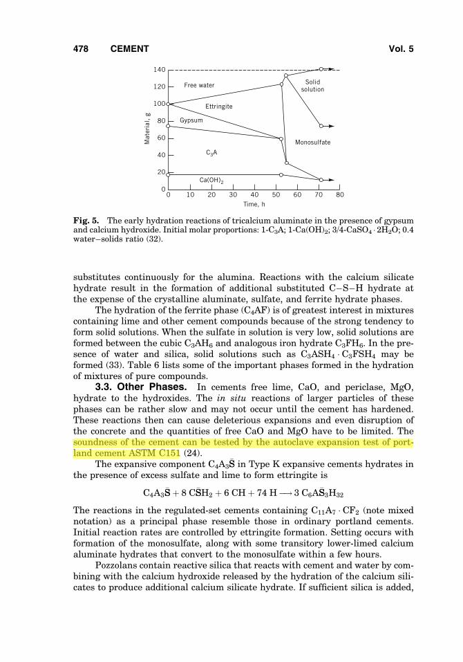
The early calcium aluminate hydration reactions in portland cements havebeen studied in simple mixtures of C3A, gypsum, calcium hydroxide, and water(32). Figure 5 shows the progressive reaction of the gypsum, water, and C3A asettringite is formed, the reaction of the ettringite, calcium hydroxide, and waterto form the monosulfate, and the solid of the monosulfate with C4AH19. Thesereactions are important in the portland cements to control the hydration of theC3A, which otherwise might hydrate so rapidly as to cause flash set, or prema-ture stiffening, in fresh concrete.
Other reactions taking place throughout the hardening period are substitu-tion and addition reactions (29). Ferrite and sulfoferrite analogues of calciummonosulfoaluminate and ettringite form solid solutions in which iron oxide
Table 5. Portland Cement Compound Hydration Reactions (Oxide Notation)
2(3CaO �SiO2)Tricalcium silicate
þ 11H2O Water ¼ 3CaO � 2SiO2 �8H2O Calciumsilicate hydrate(C-S-H)
þ 3(CaO �H2O)Calciumhydroxide
2(2CaO �SiO2)Dicalcium silicate
þ 9H2O Water ¼ 3CaO � 2SiO2 �8H2O Calciumsilicate hydrate(C-S-H)
þ CaO �H2OCalciumhydroxide
3CaO �Al2O3
Tricalciumaluminateþ 3(CaO �SO3 �
2H2O) Gypsumþ 26H2O Water ¼ 6CaO �Al2O3 �
3SO3 � 32H2OEttringite
2(3CaO �Al2O3)Tricalciumaluminate
þ 6CaO �Al2O3 �3SO3 � 32H2O)Ettringite
þ 4H2O Water ¼ 3(4CaO �Al2O3 �SO3 � 12H2O)Calcium mono-sulfoaluminate
3CaO �Al2O3
Tricalciumaluminateþ CaO �H2O
Calciumhydroxide
þ 12H2O Water ¼ 4CaO �Al2O3 �13H2O Tetra-calcium alumi-nate hydrate
4CaO �Al2O3 �Fe2O3
Tricalciumaluminoferrite
þ 10H2O Water þ 2(CaO �H2O)Calciumhydroxide
¼ 6CaO �Al2O3 �Fe2O3 � 12H2OCalciumaluminoferritehydrate
Vol. 5 CEMENT 477
substitutes continuously for the alumina. Reactions with the calcium silicatehydrate result in the formation of additional substituted C�S�H hydrate atthe expense of the crystalline aluminate, sulfate, and ferrite hydrate phases.
The hydration of the ferrite phase (C4AF) is of greatest interest in mixturescontaining lime and other cement compounds because of the strong tendency toform solid solutions. When the sulfate in solution is very low, solid solutions areformed between the cubic C3AH6 and analogous iron hydrate C3FH6. In the pre-sence of water and silica, solid solutions such as C3ASH4 � C3FSH4 may beformed (33). Table 6 lists some of the important phases formed in the hydrationof mixtures of pure compounds.
3.3. Other Phases. In cements free lime, CaO, and periclase, MgO,hydrate to the hydroxides. The in situ reactions of larger particles of thesephases can be rather slow and may not occur until the cement has hardened.These reactions then can cause deleterious expansions and even disruption ofthe concrete and the quantities of free CaO and MgO have to be limited. Thesoundness of the cement can be tested by the autoclave expansion test of port-land cement ASTM C151 (24).
The expansive component C4A3�SS in Type K expansive cements hydrates in
the presence of excess sulfate and lime to form ettringite is
C4A3�SSþ 8 C�SSH2 þ 6 CHþ 74 H�! 3 C6A�SS3H32
The reactions in the regulated-set cements containing C11A7 � CF2 (note mixednotation) as a principal phase resemble those in ordinary portland cements.Initial reaction rates are controlled by ettringite formation. Setting occurs withformation of the monosulfate, along with some transitory lower-limed calciumaluminate hydrates that convert to the monosulfate within a few hours.
Pozzolans contain reactive silica that reacts with cement and water by com-bining with the calcium hydroxide released by the hydration of the calcium sili-cates to produce additional calcium silicate hydrate. If sufficient silica is added,
120
100
80
60
40
20
0
Mat
eria
l, g
0Time, h
10 20 30 40 50 60
140
70 80
Ca(OH)2
C3A
Gypsum
Ettringite
Free water
Monosulfate
Solidsolution
Fig. 5. The early hydration reactions of tricalcium aluminate in the presence of gypsumand calcium hydroxide. Initial molar proportions: 1-C3A; 1-Ca(OH)2; 3/4-CaSO4 � 2H2O; 0.4water–solids ratio (32).
478 CEMENT Vol. 5

Table 6. Cement Phases Hydrated at Normal Temperaturesa
CASRegistry Approximate
Stability rangeDensity,
Name Number compositionb rh, 258C Temp, 8C Crystal system kg/m3
calcium sulfate dihydrate (gypsum) [10101-41-4] C�SSH2 100–35 <100 monoclinic 2.32[13397-24-5]
calcium hydroxide (portlandite) [1305-62-0] CH 100–0 <512 trigonal–hexagonal 2.24magnesium hydroxide (brucite) [1309-42-8] MH 100–0 <350 trigonal–hexagonal 2.37calcium silicate hydrate gel
(C�S�H gel)[12323-54-5] CxSyHz
c indefinite indefinite 2.7d
tetracalcium aluminate,19-hydrate [12042-86-3] C4AH19 100–85 <15 trigonal–hexagonal 1.8013-hydrate [12042-85-2] C4AH13 81–12 trigonal–hexagonal 2.027-hydrate [12511-52-3] C4AH7 2–0 to 120
tetracalcium aluminate monosulfate,16-hydrate [67523-83-5] C4A�SSH16 aq <8 trigonal–hexagonal14-hydrate [12421-30-6] C4A�SSH14 100–95 >9 trigonal–hexagonal12-hydrate [12252-10-7] C4A�SSH12 95–12 >1 trigonal–hexagonal 1.9510, 8, x-hydrate [12252-09-4]
[12445-38-4]C4A�SSHx <12
ettringite (6-calcium aluminatetrisulfate, 32-hydrate)
[12252-15-2] C6A�SS3H32 100–4 <60 trigonal–hexagonal 1.73–1.79
[11070-82-9] C6A�SS3H8 4–2 <110garnet-hydrogarnet solid solution
seriesC3ðF1�xAxÞðS1�yH2yÞ3e stable cubic
[12042-80-7] end member:C3AH6
100–0 >15 cubic 2.52
aRef. 12,13, and 34.bIn cement chemists’ notation.cWhere 1:3 < x=y < 2 and probably 1 < z=y < 1:5.dWet.ex ¼ A
A þ Fand y ¼ 2 H
2 Hþ S.
479
�30% of the weight of cement, the calcium hydroxide can eventually be comple-tely combined. Granulated blast-furnace slag is not ordinarily reactive in water,but in the presence of lime reactions occur with the silica framework. This break-down of the slag releases other components so that a variety of crystallinehydrate phases can also form.
3.4. Hydration Process. Portland cement is generally used at tempera-tures ordinarily encountered in construction, ie, from 5 to 408C. Temperatureextremes have to be avoided. The exothermic heat of the hydration reactionscan play an important part in maintaining adequate temperatures in cold envir-onments, and must be considered in massive concrete structures to preventexcessive temperature rise and cracking during subsequent cooling. Heat indueddelayed expansion (delayed ettringite expansion) can also be controlled by keep-ing the concrete temperature <708C.
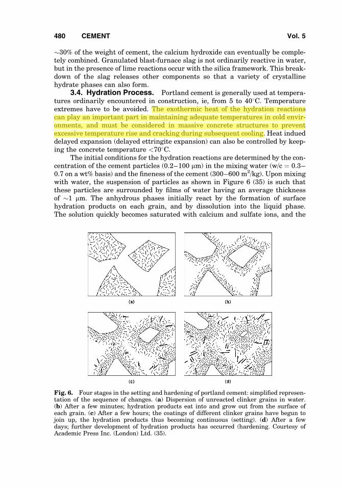
The initial conditions for the hydration reactions are determined by the con-centration of the cement particles (0.2–100 mm) in the mixing water (w/c ¼ 0.3–0.7 on a wt% basis) and the fineness of the cement (300–600 m2/kg). Upon mixingwith water, the suspension of particles as shown in Figure 6 (35) is such thatthese particles are surrounded by films of water having an average thicknessof �1 mm. The anhydrous phases initially react by the formation of surfacehydration products on each grain, and by dissolution into the liquid phase.The solution quickly becomes saturated with calcium and sulfate ions, and the
Fig. 6. Four stages in the setting and hardening of portland cement: simplified represen-tation of the sequence of changes. (a) Dispersion of unreacted clinker grains in water.(b) After a few minutes; hydration products eat into and grow out from the surface ofeach grain. (c) After a few hours; the coatings of different clinker grains have begun tojoin up, the hydration products thus becoming continuous (setting). (d) After a fewdays; further development of hydration products has occurred (hardening. Courtesy ofAcademic Press Inc. (London) Ltd. (35).
480 CEMENT Vol. 5

concentration of alkali cations increases rapidly. These reactions consume part ofthe anhydrous grains, but the reaction products tend to fill that space as well assome of the originally water-filled space. The porous hydration products occupyabout twice the volume of the reacted anhydrous material (36). The hydrationproducts at this stage are mostly colloidal (<0:1 �) but some larger crystals of cal-cium aluminate hydrates, sulfoaluminate hydrate, and hydrogarnets form. Asthe reactions proceed the coatings increase in thickness and eventually formbridges between the original grains. This is the stage of setting. Despite thelow solubility and mobility of the silicate anions, growths of the silicate hydratesalso form on the crystalline phases formed from the solution and become incor-porated into the calcium hydroxide and other phases. Upon further hydration thewater-filled spaces become increasingly filled with reaction products to producehardening and strength development.
The composition of the liquid phase during the early hydration of portlandcements is controlled mainly by the solution of calcium, sulfate, sodium, andpotassium ions. Very little alumina, silica, or iron are present in solution. Calciumhydroxide, as calcium oxide, and gypsum, as calcium sulfate, alone have solubili-ties of �1.1 and 2.1 g/L at 258C, respectively. In the presence of alkalies releasedin the first 7 min, the composition tends to be governed by the equilibrium:
CaSO4 þ 2 MOH �! � M2SO4 þ Ca OHð Þ2
where M represents the alkalies. At advanced stages of hydration of low water/cement ratio pastes, the alkali solution concentration may exceed 0.4 N with apH > 13. Saturated lime/water has a pH of 12.4 at 258C.
The exact course of the early hydration reactions depends mainly on theC3A, ferrite, and soluble alkali contents of the clinker, and the amount of gypsumin the cement. Following the rate of reaction by calorimetric measurements, atleast two and sometimes three distinct peaks in the rate of heat liberation canbe observed (33,37). A large initial peak lasts only a few minutes and mayreach 6 J/(g �min)[1.4 cal/(g �min)] resulting mainly from the solution of solubleconstituents and the surface reactions, especially the formation of the sulfoalu-minate coating on the highly reactive C3A phase. After the initial heat peak, thereactions are strongly retarded, producing a 1–2-h delay referred to as the induc-tion period during which the cement/water paste remains plastic and the con-crete is workable. The cause of the induction period is a subject of muchdebate. The most widely supported explanation of the induction period involvesan initial reaction which forms a protective layer on the C3S particles (38).Within 30 s, the C3S is almost isolated from the solution. Eventually, C�S�Hnucleates and grows. The protective layer is disrupted and increased access tothe C3S leads to an increasing rate of hydration, which produces the secondheat peak. Around the time of the second heat peak the concrete sets and estab-lishes its familiar monolithic structure. A third heat peak may be observeddepending on the gypsum and C3A contents. If present, the third peak corre-sponds to the exhaustion of the solid gypsum, a rapid decrease of sulfate in solu-tion, conversion of the ettringite to monosulfate, and renewed rapid reaction ofthe remaining C3A and ferrite phases. At optimum gypsum content the thirdpeak ordinarily occurs between 18 and 24 h.
Vol. 5 CEMENT 481

In these early reactions, the reactivities of the individual phases are impor-tant in determining the overall reaction rate. However, as the cement particlesbecome more densely coated with reaction products, diffusion of water and ionsin solution becomes increasingly impeded. The reactions then become diffusioncontrolled at some time depending on various factors such as temperature andwater/cement ratio. After �1 or 2 days, ie, at �40% of complete reaction, theremaining unhydrated cement phases react more nearly uniformly.
Microscopic examination of sections of hardened cement paste show thatthe unhydrated cores of the larger cement particles can be distinguished fromthe hydrated portion or inner product, which is a pseudomorph of the originalgrain, and the outer product formed in the originally water-filled spaces. Mea-surements of these cores indicate the depth of penetration of the hydration reac-tions (39). The overall hydration rate increases with the temperature, thefineness of the cement, and to a lesser extent with the water/cement ratio; mea-surements of the activation energy indicate that the reaction becomes increas-ingly diffusion controlled (33). Although more finely ground cements hydratemore rapidly in the first month or more of hydration, these differences graduallydisappear at later ages. After 1 year, most portland cements at usual water/cement ratios are >90% hydrated if continuously moist cured. At completehydration the chemically combined water (the water retained after strong dry-ing) is �20–25% of the weight of the cement, depending on its composition. How-ever, a minimum water/cement ratio of �0.4 is required to provide enough spaceto permit complete hydration of the cement (36). If moist curing is stopped andthe hardened cement is dried sufficiently, eg, to 80% relative humidity (rh), thehydration process stops.
4. Cement Paste Structure and Concrete Properties
The properties of both fresh and hardened mortars and concretes depend mainlyon the cement/water paste properties. Practical engineering tests are usuallymade using concrete specimens because their properties also depend on the pro-portions, size gradation, and properties of the aggregates. Quality control testingand research on cement properties is usually done on cement pastes or cementmortars made with standard sands. The properties of hardened cement pastes,mortars, and concretes are similar functions of the water/cement ratio anddegree of hydration of the cement. The properties of fresh concretes that deter-mine the workability, or ease of mixing and placement into forms, also dependstrongly on, but are not so simply related to, the cement paste rheological proper-ties (40,41).
The fresh paste even in the dormant period is normally thixotropic, or shearthinning, indicating that the structure is being continuously broken down andre-formed during mixing. It is an approximately Bingham plastic body havinga finite yield value and plastic viscosity from 5000 to 500 mPa � sð¼cPÞ as thewater/cement ratio increases from 0.4 to 0.7 (42). The viscosity and yield valuescan be greatly reduced by the addition of certain organic water-reducing admix-tures especially formulated for this purpose. Workability of concrete is measured
482 CEMENT Vol. 5

by the slump of the concrete determined after removal of a standard slump cone(305 mm high) (43). Workable concretes have slumps of 75 mm or more.
After mixing and casting, sedimentation of the cement particles in thewater results in bleeding of water to the top surface and reduction of water/cement ratio in the paste. At high water/cement ratios, some of the very fine par-ticles may be carried with the bleed water to the top resulting in laitance andperhaps the formation of flaws called bleeding channels. In concretes, sedimen-tation may cause flaws under the larger aggregate particles. If the fresh concreteis not protected from too rapid surface drying, capillary forces cause dryingshrinkage that may cause plastic shrinkage cracks. Good construction practicesare designed to minimize all of these flaws.
The engineering properties of the concrete, such as strength, elastic moduli,permeability to water and aggressive solutions, and frost resistance, dependstrongly on the water/cement ratio and degree of hydration of the cement. A vari-ety of empirical water/cement ratio laws express the strength as functions ofwater/cement ratio or porosity. The fraction of the original water-filled space,which is occupied by hydration products at any stage of hydration, is termedthe gel-space ratio X. The compressive strength of hardened cement or mortarthen approximately fits the power law:
� ¼ �oXn
where n is �3.0 and s is the intrinsic strength of the densest (X ¼ 1) gel pro-duced by a given cement under normal hydrating conditions. Values of so
range upward from 100 MPa (15,000 psi), depending on the cement composition(44). Several direct relationships between porosity, p, and strength have beenapplied to cement pastes (45–48):
� ¼ �o 1� pð ÞB
� ¼ D ln p=poð Þ
� ¼ �o 1� Epð Þ
where B, D, and E are constants. Whereas some of these equations break down atvery low or very high porosities, they all provide reasonable estimates within anintermediate porosity range. One comparative study concluded that the lastequation was the most satisfactory (49). Under extreme conditions, eg, hot press-ing at very low water/cement ratios, strengths as high as 655 MPa (95,000 psi)have been reported (50). Tensile strengths and elastic moduli are similarlydependent on porosity or gel/space ratio, but the tensile strength is only aboutone-tenth of the compressive strength. The Young’s modulus of the densest gelsproduced under normal hydrating conditions is about 34 GPa (5� 106 psi) (30).
Under sustained loads, hardened cements and concrete creep or deformcontinuously with time, in addition to the initial elastic deformation. Under nor-mal working loads this deformation may in time exceed the elastic deformationand must be considered in engineering design. This is especially true in pre-stressed concrete structural members in which steel tendons under high tensilestress maintain compressive stress in the concrete to prevent tensile cracking
Vol. 5 CEMENT 483

during bending. Both creep and drying shrinkage of the concrete may lead to lossof prestress. Some creep in ordinary concrete structures and in the cement pastebetween the aggregate particles can also be an advantage because it tends toreduce stress concentrations, cracking, and microcracking around aggregateparticles.
Drying of hardened cements results in shrinkage of the paste structure andof concrete members. Linear shrinkage of hardened cements is �0.5% whendried to equilibrium at normal (�50%) relative humidities. The cement gel struc-ture is somewhat stabilized during drying so that upon subsequent wetting anddrying smaller changes occur. Concretes shrink much less (�0.05%), dependingon the volume fractions of cement paste and aggregates, water/cement ratio, andother factors. Drying of concrete structural members proceeds very slowly andresults in internal shrinkage stresses because of the moisture gradients duringdrying. Thick sections continue to dry and shrink for many years. Atmosphericcarbon dioxide penetrates the partly dried concrete and reacts with the calciumsilicate hydrate gel, as well as with calcium aluminate hydrates, releasing addi-tional water and causing additional shrinkage. The density of the hydration pro-ducts is increased, however, and the strength is actually increased. This reactionis sometimes used to advantage in the manufacture of precast concrete productsto improve their ultimate strength and dimensional stability by precarbonation.
The slowness of drying and the penetration of the hardened cement by car-bon dioxide or chemically aggressive solutions, eg, seawater or sulfate groundwaters, is a result of the small sizes of the pores. Initially, the pores in thefresh paste are the water-filled spaces (capillaries) between cement particles.As these spaces become subdivided by the formation of the hydration products,the originally continuous pore system becomes one of more discrete pores orcapillary cavities separated from each other by gel formations in which theremaining pores are very much smaller. These gel pores are so small (�3-nmnominal diameter) that most of the water contained in them is strongly affectedby the solid surface force four fields. These force fields are responsible for a largeincrease in the viscosity of the water and a decrease in mobility of ionic species insolution. Hence, the permeability of the paste to both water and dissolved sub-stances is greatly reduced as hydration proceeds. This in part accounts for thegreat durability of concrete, especially when water/cement ratios are kept lowand adequate moist curing ensures a high degree of hydration. High water/cement ratios result in large numbers of the capillary spaces (0.1 mm and larger)interconnected through capillaries that are 10 nm or larger. These capillaries notonly lower the strength, but also permit the easy penetration of aggressive solu-tions. Furthermore, these capillary spaces may become filled with water whichfreezes < 08C, resulting in destructive expansions and deterioration of theconcrete.
5. Chemical Admixtures
Admixtures include materials other than cement, water, or aggregate addedimmediately before or during mixing. Admixtures serve a broad range of
484 CEMENT Vol. 5

purposes including the control of setting, control of workability, and control of aircontent.
5.1. Retarders and Accelerators. Materials that control hardening ofcement may be either organic or inorganic. Retarders are often incorporated inoil well cementing and hot-weather concrete applications, whereas acceleratorsmay be useful for cold-weather concrete applications in which higher rates ofreactivity are desirable. In most cases, these admixtures are used in low concen-trations, suggesting that they act by adsorption.
5.2. Water-Reducers and Plasticizers. Common admixtures thatimprove fluidity of concrete mixes are often used in high strength concrete.These admixtures make possible the incorporation of silica fume while main-taining necessary workability. Three principal types of superplasticizers are incommon use: salts of sulfonated melamine formaldehyde polymers; salts ofsulfonated naphthalene formaldehyde polymers; and modified lignosulfonatematerials (see AMINO RESINS; LIGNIN; PHENOLIC RESINS). One benefit of these admix-tures is improved dispersion of cement grains in the mixing water.
5.3. Air-Entraining Admixtures. Materials that are used to improvethe ability of concrete to resist damage from freezing are generally known asair-entraining admixtures. These surfactant admixtures (see SURFACTANTS) pro-duce a foam that persists in the mixed concrete, and serves to entrain manysmall spherical air voids that measure from 10 to 250 mm in diameter. The airvoids alleviate internal stresses in the concrete that may occur when the poresolution freezes. In practice, up to 10% air by volume may be entrained in con-crete placed in severe environments.
6. Manufacture
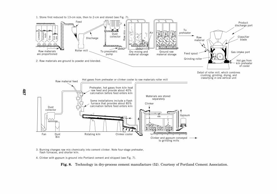
6.1. Portland Cements. The process of portland cement manufactureconsists of (1) quarrying and crushing the rock, (2) grinding the carefully propor-tioned materials to high fineness, (3) subjecting the raw mix to pyroprocessing ina rotary kiln, and (4) grinding the resulting clinker to a fine powder. A layout of atypical plant is shown in Figure 7 (51). Figure 8 gives the layout of a newer dryprocess plant (52). No new wet process plants are being built, and existing wetprocess plants are gradually being replaced by dry process plants (only 32.8% arewet process). The plants outlined are typical of installations producing approxi-mately 1000 metric tons per day. Modern installations (53–55) are equipped withinnovations such as suspension or grate preheaters, roller mills, or precalcinerinstallations.
Because calcium oxide comprises �65% of portland cement, these plants arefrequently situated near the source of their calcareous material. The requisitesilica and alumina may be derived from a clay, shale, or overburden from a lime-stone quarry. Such materials usually contain some of the required iron oxide, butmany plants need to supplement the iron with mill scale, pyrite cinders, or ironore. Silica may be supplemented by adding sand to the raw mix, whereas alu-mina can be furnished by bauxites and Al2O3-rich kaolinitic clays.
Industrial byproducts are becoming more widely used as raw materials forcement, eg, slags contain carbonate-free lime, as well as substantial levels of
Vol. 5 CEMENT 485

Wet
pro
cess
or
Dry
pro
cess
Limestone
ShaleTo crusher
Primary crusher
To vibrat
ing scre
en
Each raw materialis stored separately
Raw materials conveyed to grinding mills1. Stone is first reduced to 13- cm size, then to 2-cm and stored.
2. Raw materials are ground to powder and blended.
2. Raw materials are ground, mixed with water to form slurry, and blended.
Secondarycrusher
Raw materials consist of combinations of limestone, cement rock, or oyster shells,
and shale, clay, sand, or iron ore.
To air separator
Cem
ent
rock
Cla
y
Iron ore
Lim
esto
ne
Raw materialsare proportioned Grinding mill
Oversi
zeFi
nes
To pneumatic pump
Dust collector
Hot airfurnace
Raw
mix
Air
Dry mixing andblending silos
Ground rawmaterial storage
To kiln
To kiln
Drilling rig
Cla
y
Iron ore
Lim
esto
ne
Raw materialsare proportioned
Wateraddedhere Oversize
Grinding mill
Slurry
Slurrypump
Fine
s
Vibrating screen
Slurry is mixed and blended
Slurrypumps
Storagebasins
3. Burning changes raw mix chemically into cement clinker.
To kilnDustcollector
Fan Dustbin
Rotating kiln Clinker cooler
Coal, oil, orgas fuel
Raw mix is kiln burnedto partial fusion at 1480 C
ClinkerMaterials are stored separately
Gypsum
Clinker and gypsum conveyed to grinding mills
Air
4. Clinker with gypsum is ground into Portland cement and shipped.
Overburden
Clink
er
Gyp
sum
Materials arestored separately
Oversize
Air separator
Fines
Dustcollector
Grinding mill
Cement pump Bulk storage Bulk truck
Bulkcar
Boxcar
Packagingmachine
Truck
Cem
ent
rock
Fig. 7. Steps in the manufacture of portland cement (51). Courtesy of Portland CementAssociation.
486 CEMENT Vol. 5
Air
1. Stone first reduced to 13-cm size, then to 2-cm and stored (see Fig. 7).
2. Raw materials are ground to powder and blended.
3. Burning changes raw mix chemically into cement clinker. Note four-stage preheater, flash furnaces, and shorter kiln.
4. Clinker with gypsum is ground into Portland cement and shipped (see Fig. 7).
Raw materialsare proportioned
Feed
Roller mill
Discharge
Dustcollector
To pneumatic pump
Raw
mix
Dry mixing andmaterial storage
Ground rawmaterial storage
Topreheater
Rawmaterial
Feed spout
Grinding roller
Productdischarge port
Classifierblade
Gas intake port
Hot gas from kiln preheater
of cooler
Detail of roller mill, which combinescrushing, grinding, drying, andclassifying in one vertical unit
Hot gases from preheater or clinker cooler to raw materials roller millRaw material feed
Dustcollector
Fan DustBin
Rotating kiln Clinker coolerClinker and gypsum conveyed
to grinding mills
Gypsum
Clinker
Materials are stored separately
Preheater, hot gases from kiln heatraw feed and provide about 40%
calcination before feed enters kiln
Some installations include a flashfurnace that provides about 85%calcination before feed enters kiln
Cla
y
Iron ore
Cem
ent
rock
Lim
esto
ne
Air
Fig. 8. Technology in dry-process cement manufacture (52). Courtesy of Portland Cement Association.
487
silica and alumina. Fly ash from utility boilers can often be a suitable feed com-ponent, because it is already finely dispersed and provides silica and alumina.Even vegetable wastes, such as rice hull ash, provide a source of silica. Probably50% of all industrial byproducts are potential raw materials for portland cementmanufacture.
Clinker production requires large quantities of fuel. In the United States,coal (qv) and natural gas are the most widely used kiln fuels but fuels derivedfrom waste materials, eg, tires, solvents, etc, are increasing in importance (53)(see FUELS FROMWASTE; GAS, NATURAL). In addition to the kiln fuel, electrical energyis required to power the equipment. This energy, however, amounts to only aboutone-ninth that of the kiln fuel. The cement industry carefully considers all mea-sures that can reduce fuel demand.
Raw Materials Preparation. The bulk of the raw material originates inthe plant quarry when control of the clinker composition starts with systematiccore drillings and selective quarrying. A primary jaw or roll crusher is frequentlylocated within the quarry reducing the quarried limestone or shale to �100-mmtop size. A secondary crusher, usually roll or hammer mills, gives a product of�10–25-mm top size. Clays may require treatment in a wash mill to separatesand and other high silica material. Combination crusher-dryers utilize exitgases from the kiln or clinker cooler to dry wet material during crushing.
Argillaceous, siliceous, and ferriferous raw mix components are added tothe crusher product. At the grinding mills, the constituents are fed into themill separately, using weigh feeders or volumetric measurements. Ball millsare used for wet and dry processes to grind the material to a fineness suchthat only 15–30 wt% is retained on a 74 mm (200 mesh) sieve. In the wet processthe raw materials are ground with �30–40% water, producing a well-homoge-nized mixture called slurry. Low concentrations of slurry thinners may beadded, such as sodium carbonates, silicates, and phosphates, as well as lignosul-fonates and modified petrochemicals. Filter presses or other devices are some-times used to remove water from slurries before feeding into the kiln.
Raw material for dry process plants is ground in closed-circuit ball millswith air separators, which may be set for any desired fineness. Autogenousmills, which operate without grinding media are not widely used. For suspensionpreheater-type kilns, a roller mill utilizes the exit gas from the preheater to drythe material in suspension in the mill.
A blending system provides the kiln with a homogeneous raw feed. In thewet process, the mill slurry is blended in a series of continuously agitated tanksin which the composition, usually theCaO content, is adjusted as required. Thesetanks may also serve as kiln feed tanks, or the slurry after agitation is pumped tolarge kiln feed basins. Dry-process blending is usually accomplished in a silowith compressed air.
Pyroprocessing. Nearly all cement clinker is produced in large rotarykiln systems. The rotary kiln is a highly refractory-lined cylindrical steel shell(3–8 m dia, 50–230 m long) equipped with an electrical drive to rotate at 1–3 rpm. It is a countercurrent heating device slightly inclined to the horizontalso that material fed into the upper end travels slowly by gravity to be dischargedonto the clinker cooler at the discharge end. The burners at the firing endproduce a current of hot gases that heats the clinker and the calcined and raw
488 CEMENT Vol. 5

materials in succession as it passes upward toward the feed end. Highly refrac-tory bricks of magnesia or alumina (see REFRACTORIES) line the firing end,whereas in the less heat-intensive midsection of the kiln bricks of lower refrac-toriness and thermal conductivity can be used, changing to abrasion-resistantbricks or monolithic castable lining at the feed end. To prevent excessive thermalstresses and chemical reaction of the kiln refractory lining, it is necessary to forma protective coating of clinker minerals on the hot face of the burning zone brick.This coating also reduces kiln shell heat losses by lowering the effective thermalconductivity of the lining.
It is desirable to cool the clinker rapidly as it leaves the burning zone. Thisis best achieved by using a short, intense flame as close to the discharge as pos-sible. Heat recovery, preheating of combustion air, and fast clinker cooling areachieved by clinker coolers of the traveling-grate, planetary, rotary, or shafttype. Most commonly used are grate coolers where the clinker is conveyedalong the grate and subjected to cooling by ambient air, which passes throughthe clinker bed in crosscurrent heat exchange. The air is moved by a series ofundergrate fans, and becomes preheated to 370–8008C at the hot end of thecooler. It then serves as secondary combustion air in the kiln; the primary airis that portion of the combustion air needed to carry the fuel into the kiln anddisperse the fuel.
During the burning process, the high temperatures cause vaporization ofalkalies, sulfur, and halides. These materials are carried by the combustiongases into the cooler portions of the kiln system where they condense, or theymay be carried out to the kiln dust collector, usually a fabric filter or electrostaticprecipitator, together with partially calcined feed and unprocessed raw feed.This kiln dust is reusable. However, the levels of total SO3 and alkali contentof cement are limited by considerations of product performance and somenational specifications, so that it is not always feasible to recycle all the dustin the process. Other potential and actual uses of dust include fertilizer supple-ments (see FERTILIZERS), acid mine waste neutralization (see WASTES, INDUSTRIAL),boiler SO2 control, and soil stabilization (qv).
Wet-Process Kilns. In a long wet-process kiln, the slurry introduced intothe feed end first undergoes simultaneous heating and drying. The refractory lin-ing is alternately heated by the gases when exposed and cooled by the slurrywhen immersed; thus the lining serves to transfer heat, as do the gases them-selves. Large quantities of water must be evaporated, thus most wet kilns areequipped with chains to maximize heat transfer from the gases to the slurry.Large, dense chain systems permit energy savings of up to 1.7 MJ/kg (731 Btulb) clinker in exceptionally favorable situations (53). After most of the moisturehas been evaporated, nodules, which still contain combined water, move downthe kiln and are gradually heated to �5508C. At this temperature, aluminosili-cates decompose, evolving combined water, and leaving a mixture to highly reac-tive microcrystalline silica and alumina together with alkaki hydroxides.
At �6508C low temperature melts of alkali chlorides, sulfates and silicatesstart to form. These promote the decomposition of calcium carbonate. Initially,the decomposing calcium carbonate reacts directly with reactive silica and alu-mina to form the low-temperature forms of belite and a mixture of low lime alu-minates. In these conditions, silica can be thought of as an ‘‘acid’’ chemically
Vol. 5 CEMENT 489

decomposing the calcite. Little free calcium oxide forms. This reaction acceler-ates as the temperature reises, and when the equilibrium temperature of decom-position of calcium carbonate (898.68C) is reached the combination of silica andalumina is almost complete. This uses up �70% of the available calcium carbo-nate and the initial endothermic silicate formation is as follows:
CaCO3 þ 0:5 SiO2 ! 0:5 Ca2SiO4 þ CO2 " ð�H ¼ þ115 kJ �mol�1ÞAbove 9008C, thermal decomposition of the remaining calcite proceeds
rapidly with the formation of free calcium oxide in another endothermic reaction:
CaCO3 ! CaOþ CO2 " ð�H ¼ þ178 kJ �mol�1ÞBecause these two reaction involve a large enthalpy transfer, a large pro-
portion of the kiln system (the calcinations zone) is used for their completion.Once the latter reaction is complete, at �10508C the temperature of the chargerises rapidly. At 13008C, the aluminates begin to melt. The resulting liquid thenacts as a solvent for the finishing reaction in which belite is converted to alite:
Ca2SiO4 þ CaO! Ca3SiO5 ð�H ¼ þ13 kJ �mol�1ÞThis occurs in the burning zone. The reaction proceeds at an economically
viable rate when the charge is raised to a peak temperature between 1400 and14508C in commercial kilns–the temperature needed depending on the burnabil-ity of the mix. Burnability depends on the fineness, homogeneity, and LSF of themix.
As the charge leaves the burning zone it begins to cool, and tricalcium alu-minate and magnesia crystallize from the melt and the liquid phase finally soli-difies to produce the ferrite phase. The material drops into the clinker cooler forfurther cooling by air.
Dry-Process Kilns, Preheaters, and Precalciners. The dry process forcement manufacture utilizes a dry kiln feed rather than a slurry. Early dry-pro-cess kilns were short, and the substantial quantities of waste heat in the exitgases from such kilns were frequently used in boilers for electric power genera-tion (qv); the power generated was frequently sufficient for all electrical needs ofthe plant. In one modification, the kiln has been lengthened and chains havebeen added; however, these serve almost exclusively a heat-exchange function(see HEAT EXCHANGE TECHNOLOGY). Refractory heat-recuperative devices, such ascrosses, lifters, and trefoils, have also been installed so that the long dry kilnis energy efficient. Other than the need for evaporation of water, its operationis similar to that of a long wet kiln.
A second type of modern dry-process kiln is the suspension preheater sys-tem (56). The dry, pulverized feed passes through a series of cyclones where it isseparated and preheated several times. The partially calcined feed exits the pre-heater tower into the kiln at �800–9008C. The kiln length required for comple-tion of the process is considerably shorter than that of conventional kilns, andheat exchange is very good. Suspension preheater kilns are very energy efficient:as low as 3.1 MJ/kg (1334 Btu/lb) clinker in large installations. The intimate mix-ing of the hot gases and feed in the preheaters promotes condensation of alkaliesand sulfur on the feed, sometimes resulting in objectionably high alkali and
490 CEMENT Vol. 5
sulfur contents in the clinker. To alleviate this problem, some of the salt-ladenkiln exit gases can be deverted to waste (bypassed) and fewer cyclone stagesused in the preheater. The wasteage of the heat in these gases results in lowerthermal efficiency.
The success of preheater kiln systems led to the development of precalcinerkiln systems. These units utilize a second burner to carry out calcination in aseparate vessel attached to the preheater. The flash furnace (57), eg, utilizes pre-heated combustion air drawn from the clinker cooler and kiln exit gases and isequipped with burner that burns �60% of the total kiln fuel. The raw material iscalcined almost 95%, and the gases continue their upward movement throughsuccessive preheater stages in the same manner as in an ordinary preheater.
The precalciner system permits the use of smaller kilns because only actualclinkering is carried out in the rotary kiln. Energy efficiency is comparable tothat of a preheater kiln, except that the energy penalty for bypass of kiln exitgases is reduced because only �40% of the fuel is being burned in the kiln. Pre-calciner kilns produce up to 10,000 metric tons of clinker per day; the largest longwet-process kiln, in the United States produces only 3270 t/day by comparison.The burning process and clinker cooling operations for the modern dry-processkiln systems are the same as for long wet kilns.
Finish Grinding. The cooled clinker is conveyed to clinker storage ormixed with 4–6% gypsum and introduced directly into the finish mills. The clin-ker and gypsum are ground to a fine, homogeneous powder having a surface areaof �300–600 m2/kg. About 85–96% of the product is in particles having <45 mmdia. These objectives may be accomplished by two different mill systems. In open-circuit milling, the material passes directly through the mill without any separa-tion. A wide particle size distribution range is usually obtained with substantialamounts of very fine and rather coarse particles. In closed-circuit grinding themill product is carried to a cyclonic air separator in which the coarse particlesare rejected from the product and returned to the mill for further grinding.Energy requirements for finish grinding vary in the range 33� 77 kW � h=tcement, depending primarily on the required fineness, but also on the natureof the clinker.
Computer Control. Process computer control was introduced to thecement industry in the 1960s and a plant of a capacity of 1 million metric tonsper year was built and placed in operation in 1973 having complete computerprocess and segmental control (58). Other plants have been built and someolder plants computerized (59). Variables can be measured at intervals of 0.25 sand overall optimum response to operating problems is programmed, not alwayspossible with manual operation. The rotary kiln is the largest and most difficultequipment to operate. Due to the hot, corrosive and abrasive condition. Tempera-ture-sensing and gas-analyzing devices present special problems.
Quality Control. Beginning at the quarry operation, product quality ismaintained by adjustments of composition, burning conditions, and finish grind-ing. Control checks are made for fineness of materials, chemical composition, anduniformity. Clinker burning is monitored by weighing a portion of sized clinker,known as the liter weight test, a free lime test, or checked by microscopic evalua-tion of the crystalline structure of the clinker compounds. Samples may beanalyzed by X-ray fluorescence, atomic absorption, and flame photometry
Vol. 5 CEMENT 491

(see SPECTROSCOPY OPTICAL). Wet chemical analysis is described in ASTM C114(24) and EN 680, but X-ray fluorescence analysis is usually used for quality con-trol in most cement plants. Standard cement samples are available from theNational Institute of Standards and Technology. Fineness of the cement ismost commonly measured by the air permeability method. Finally, standardizedperformance tests are conducted on the finished cement (24).
Environmental Pollution Control. The cement industry has had an inten-sive program of capital expenditure to install dust collection equipment on kilnsand coolers since the 1970s (60). Modern equipment collects dust at 99.8% effi-ciency. Many smaller dust collectors are installed in new plants (61).
Government agencies have (62) established limits for cement plant efflu-ents including water run-off from manufacturing facilities, quarrying, raw mate-rial storage piles, and wastewater. Compliance with these standards hasrequired construction of diversion ditches for surface water, ponds for settlingand clarification, dikes and containment structures for possible oil spills, andchemical water treatment in some cases. Since the cement industry obtainsmost of its raw material by quarrying, the standards for the mineral industryalso apply.
One of the primary waste products of cement manufacturing is cement kilndust (CKD). The CKD is collected from exhaust gases and either returned to thekiln with other raw materials or disposed of as landfill. CKD is also used in otherapplications, such as synthetic aggregate and tends to accumulate very low con-centrations of heavy metals that originate in the fuels or in the raw materials.These metals volatilize in the high temperatures of the kiln and become asso-ciated with exhaust gases. Two significant studies of CKD (63,64) concludedthat the environmental considerations are minor and that neither CKD norcement have characteristics of hazardous waste as defined under the U.S.Resource Conservation and Recovery Act. The cement industry continues tosearch for new uses for CKD in construction applications.
6.2. Special Purpose and Blended Cements. Special purpose andblended portland cements are manufactured essentially by the same processesas ordinary portland cements, but have specific compositional and process differ-ences. White cements are made from raw materials of very low iron content. Thistype is often difficult to burn because almost the entire liquid phase must befurnished by calcium aluminates. As a consequence of the generally lower totalliquid-phase content, high burning-zone temperatures may be necessary. Fastcooling (quenching) and occasionally supplementary reducing flame impingingon the charge at the kiln exit (bleaching) are needed to maintain both qualityand color.
Regulated set cements are made using fluorite, CaF2, additions which alsoact as fluxing agents, or mineralizers, to reduce burning temperatures. The clin-ker produced then containsC11A7 � CaF2, (mixed notation) as a principal phase.Another regulated set cement can be made in which the principal constituentsare C4A3
�SS and belite. Both cements rapidly harden and can reach modest com-pressive strengths within several hours. Final material properties are in mostrespects similar to comparable concretes made with portland cement.
Concern with regard to energy conservation has prompted the use of by-product materials in portland cement concrete. Blended hydraulic cements are
492 CEMENT Vol. 5

produced by intimately and uniformly blending two or more types of fine materi-als. The primary blending materials are portland cement, ground granulatedblast-furnace slag, fly ash, calcined clay, silica fume, and hydrated lime. Cementkiln dust and other materials are undergoing research for use in blendedcements. Blended hydraulic cements can conform to the requirements ofASTM C 595, or ASTM C 1157. ASTM C 595 recognizes five classes of blendedcements: portland blast-furnace slag cement, Type IS; portland–pozzolan cement,Type IP and Type P; slag cement, Type S; pozzolan-modified portland cement,Type I (PM); and slag-modified portland cement, Type I (SM). ASTM C 1157cement types, which apply to both portland and blended cements, include gen-eral purpose cement, Type GU; high early strength cement, Type HE; moderateheat cement, Type MH; low heat cement, Type LH; moderate sulfate resistantcement, Type MS; and high sulfate resistant cement, Type HS.
Blended cements represent �2% of the cement shipped in the UnitedStates. In Europe, the use of blended cement is very common. Most of theblended cement used in the United States is Type IP and it is used in thesame applications as that of regular Type I or II portland cement.
ASTM C845 Type E-I (K) expansive cement manufactured in the UnitedStates usually depends on aluminate and sulfate phases that result in moreettringite formation during hydration than in normal portland cements. TypeK contains an anhydrous calcium sulfoaluminate. This cement can be madeeither by integrally burning to produce the desired phase composition, or byintergrinding a special component with ordinary portland cement clinkers andcalcium sulfate.
Oil well cements are manufactured similarly to ordinary portland cementsexcept that the goal is usually sluggish reactivity. For this reason, levels of C3A,C3S, and alkali sulfates are kept low. Hydration–retarding additives are alsoemployed.
Pozzolans include natural materials such as diatomaceous earths (seeDIATOMITE), opaline cherts, and shales, tuffs, and volcanic ashes or pumicites,and calcined materials such as some clays and shales. Byproducts such as flyashes and silica fume are also employed. In the United States the proportionof pozzolan interground with clinker has varied from 15 to >30%, whereas inItaly, cements with a 30–40% pozzolan content are produced.
Portland cement clinker is also interground with 10–65% granulated blast-furnace slag to produce a Portland blast-furnace slag cement. The compositionof the slag varies considerably but usually falls within the following wt% com-position ranges: CaO, 40–50%, SiO2, 30–40%, Al2O3, 8–18%; MgO, 0–8%; S(sulfide), 0–2%; and FeO, and MnO, 0–3%.
Masonry cements are used for making mortar for bricklaying. They are notsuitable for use in concrete. Most masonry cements are finely interground mix-tures where portland cement is a principal constituent. These cements alsoinclude finely ground limestones, hydrated lime, natural cement, pozzolans,clays, or air-entraining agents. Secondary materials are used to impart therequired water retention and plasticity to mortars.
6.3. Non-Portland Cements. Calcium Aluminate Cements. Thesecements are manufactured by heating until molten or by sintering a mixture oflimestone and a bauxite containing low amounts of SiO2, FeO, and TiO2 (see
Vol. 5 CEMENT 493

ALUMINUM COMPOUNDS, ALUMINUM OXIDE, CALCINED, TABULAR, AND ALUMINATE CEMENTS).The process is usually carried out in an open-hearth furnace having a longvertical stack into which the mixture of raw materials is charged. The hotgases produced by a blast of pulverized coal and air pass through the chargeand carry off the water and carbon dioxide. Fusion occurs when the chargedrops from the vertical stack onto the hearth at �1425–15008C. The moltenliquid runs out continuously into steel pans on an endless belt in which themelt solidifies. Special rotary kilns, provided with a tap hole from which the mol-ten liquid is drawn intermittently, and electric arc furnaces have also been used.
When calcium aluminate cements are made by the fusion process, the soli-dified melt must be crushed and then ground. The material is very hard to grindand power consumption is high.
6.4. Hydraulic Limes. These materials are produced by heating belowsintering temperature a limestone containing considerable clay, during which
Table 7. United States Portland Cement Consumptiona
U.S Cement Industry Consumption — Exports — Imports — Shipmentsb
Consumptionc Total
YearPortlandcement
Masonrycement Total
Cementexports
Cementimports
shipmentsby domesticd
products
1979 75,523 3,343 78,866 244 4,101 75,0321980 66,940 2,721 69,661 346 2,732 67,7101981 63,456 2,440 65,896 614 2,287 64,3381982 57.191 2,166 59,357 384 2,367 57,5441983 62,918 2,615 65,533 292 2,522 63,5841984 71,792 2,945 74,737 266 6,004 70,4351985 74,434 2,960 77.394 258 8,845 70,2351986 78,643 3,230 81,873 227 11,661 71,3861987 80,291 3,375 83,666 271 13,184 71,2431988 80,715 3,292 84,007 197 14,001 70,4271989 79,155 3,071 82,226 300 12,547 70,3211990 77,785 3,005 80,790 293 10,461 71,5351991 69,098 2,495 71,593 272 7,215 64,8421992 73,354 2,704 76,058 351 6,097 70,5021993 76,566 3,014 79,580 398 6,151 73,9341994 82,159 3,267 85,426 452 8,912 77,0211995 82,825 3,160 85,985 485 11,625 74,9361996 87,416 3,399 90,815 461 11,999 79,4111997 92,708 3,458 96,166 519 13,814 82,9781998 99,153 4,101 103,254 322 18,278 85,4171999 104,074 4,352 108,426 315 22,534 86,3282000 105,195 4,333 109,528 394 22,740 87,5992001 108,090 4,475 112,565 443 22,397 91,097
aRef. 69.bThousands of metric tons.cExcludes Alaska and Puerto Rico.dExcludes Puerto Rico.
Note: Domestic Shipments include cement shipments from domestic manufacturers and cement ship-ments ground from imported clinker, but exclude finished cement imports.
Source: U.S. Geological Survey/PCA Economic Research.
494 CEMENT Vol. 5

some combination takes place between the lime and the oxides of the clay to formhydraulic compounds.
7. Economic Aspects
From the beginning of the United States portland cement industry in 1872,annual cement consumption grew through 1970. From 1975 to 1990, cement con-sumption changed little. During the 1990s, cement consumption continued togrow. Table 7 gives United States’ production figures and Table 8 gives theworld production. China, having an annual output of >580 million metric tonsin 2000, has emerged as the world’s leading cement producer (68).
Since the 1940s, the cement industry reduced labor and energy costs byincreased investment in capital equipment and larger plants to remain competi-tive with other building materials industries (see BUILDING MATERIALS, SURVEY;BUILDING MATERIALS, PLASTIC). The average plant size more than doubled between1950 and 1990.
7.1. Energy Use. From 1972 to 2000, the cement industry has reducedunit energy usage by 32.9%. The wet process, used in 60% of the plants in the1960s, was less labor-intensive than the dry process. However, as energy costsescalated in the early 1970s, the more energy efficient dry-process manufactur-ing was preferred. According to 1989 figures, wet-process plants consume 38%more energy per ton of cement than dry-process plants.
Coal is the primary kiln fuel as seen in Table 9. Energy from coal rose from36 to 60% of the total energy required for cement production between 1972 and2000.
7.2. Marketing Patterns. The cement industry reduced its dependenceon bag (container) shipments (54.7% in 1950) and turned to the more labor-effi-cient bulk transport (96% in 2000). In addition, the amount of cement shipped byrail transportation declined from 75% of industry shipments in 1950 to <2% in2000. Table 10 summarizes the shipment distribution by cement type.
In the past 30 years, the ready-mixed concrete industry became the primarycustomer for cement manufacturers. In 2000, >73.7% of the cement shippedwas sold to the ready-mixed concrete industry, compared with 63% in 1975. Theother primary uses are in building materials, concrete products, and highwayconstruction.
8. Environmental Aspects
Cement plants in the United States are carefully monitored for compliance withEnvironmental Protection Agency (EPA) standards for emissions of particulates,SOx, NOx, and hydrocarbons. All plants incorporate particulate collection devicessuch as baghouses and electrostatic precipitators (see AIR POLLUTION CONTROL
METHODS). The particulates removed from stack emissions are called cementkiln dust (CKD). It has been shown that CKD is characterized by low concentra-tions of metals which leach from the CKD at levels far below regulatory limits(63,64).
Vol. 5 CEMENT 495

Table 8. Top World Producers of Portland Cementa
Top World Producers of Hydraulic Cementb
1991 1992 1993 1994 1995 1996 1997 1998 1999 2000c
China 252,610 308,220 367,880 421,180 475,910 491,190 511,730 536,000 573,000 583,190India 51,000 50,000 53,812 57,000 62,000 75,000 80,000 85,000 90,000 95,000United Statesd 68,465 70,883 75,117 79,353 78,320 80,818 84,255 85,522 87,777 89,510Japan 89,564 88,253 88,046 91,624 90,474 94,492 91,938 81,328 80,120 81,300Korea, Republic of 34,999 44,444 47,313 50,730 55,130 58,434 60,317 46,091 48,157 51,255Brazil 27,490 23,903 24,843 25,230 28,256 34,597 38,096 39,942 40,270 39,208Germany 34,396 37,529 36,649 36,130 33,302 31,533 35,945 36,610 38,099 38,000Italy 40,806 41,347 33,771 32,713 33,715 33,327 33,721 35,512 34,000 36,000Turkey 26,091 28,607 31,241 29,493 33,153 35,214 36,035 38,200 34,358 35,825Russia 27,800 26,700 26,000 28,400 32,400Thailand 18,054 21,832 26,870 29,900 34,900 38,749 37,086 30,000 34,000 32,000Mexico 25,100 26,880 27,120 29,700 24,043 25,366 27,548 27,744 29,413 31,677Spain 25,119 24,615 22,878 25,150 26,423 25,157 27,632 27,943 30,800 30,000Total Worlde 1,181.8 1,231.1 1,290.9 1,370.0 1,445.0 1,493.0 1,547.0 1,547.0 1,603.0 1,643.0
aRef. 69.bThousands of metric tons.cestimate.dIncludes Puerto Rico.eMillion metric tons.
Source: U.S. Geological Survey.
496

Table 9. United States Portland Cement Industry Energy Consumptiona
Summary of Energy Consumptionb % Change
1972 1995 1996 1997 1998 1999 2000 00/72 00/95
Gasoline 7.4 2.4 2.0 1.8 1.9 2.2 4.6 �37.8% 91.7%Middle distillates 88.3 38.1 43.6 39.7 41.3 44.7 39.4 �55.4% 3.4%Residual oil 808.9 17.1 6.0 8.1 6.9 3.6 3.9 �99.5% �77.2%LPG 1.4 0.6 0.6 0.4 0.4 0.3 0.3 �78.8% �50.0%Total Petroleum Products 906.0 58.2 52.2 50.0 50.5 50.8 48.2 �94.7% �17.2%Natural gas 3,347.1 564.0 374.6 305.2 372.4 327.7 261.6 �92.2% �53.6%Coal 2,639.0 2,887.2 3,052.6 3,110.2 2,998.6 2,984.0 2,984.1 13.1% 3.4%Petroleum Coke 39.6 814.9 798.1 732.8 744.1 748.8 760.7 1821.0% �6.7%Total Coal and Coke 2,678.6 3,702.1 3,850.7 3,843.0 3,742.7 3,732.8 3,744.8 39.8% 1.2%Waste fuel � 416.2 389.5 444.4 413.5 407.8 402.5 � �3.3%Total Fossil Fuels 6,931.7 4,740.5 4,667.0 4,642.6 4,579.1 4,519.1 4,457.1 �35.7% �6.0%Electricity 488.6 520.9 533.7 528.7 528.1 520.8 524.6 7.4% 0.7%
Total Fuel and Power 7,420.3 5,261.4 5,200.7 5,171.3 5,107.2 5,039.9 4,981.7 �32.9% �5.3%aRef. 69.bThousands of BTUs per equivalent metric ton. Weighted average of 92% clinker production plus 8% finished cement production.
Source: PCA U.S. and Canadian Labor-Energy Input Services.
497

9. Specifications and Types
Portland cements are manufactured to comply with specifications established ineach country (70). In the United States, several different specifications are used,including those of the American Society for Testing and Materials and AmericanAssociation of State Highway and Transportation Officials (AASHTO). TheASTM annually publishes test methods and standards (24), which areestablished on a consensus basis by its members which include consumers andproducers.
In the United States, portland cement is classified in five general typesdesignated by ASTM Specification C150 (24): Type I, when the special propertiesare not required; Type II, for general use, and especially when moderate sulfateresistance or moderate heat of hydration is desired; Type III, for high earlystrength; Type IV, for low heat of hydration; and Type V, for high sulfate resis-tance. Types I, II, and III may also be specified as air entraining. Chemical com-positional, physical, and performance test requirements are specified for eachtype; optional requirements for particular uses may also be specified. Portlandcement can also be specified under ASTM C 1157 as general purpose cement,Type GU; high early strength cement, Type HE; moderate heat cement, TypeMH; low heat cement, Type LH; moderate sulfate resistant cement, Type MS;and high sulfate resistant cement, Type HS. Tables 11 and 12 list applications
Table 10. United States Portland Cement Shipments by Typea
Portland Cement Shipped from U.S. Plants by Type of Productb
1998 1999 2000
Quantity% ofTotal Quantity
% ofTotal Quantity
% ofTotal
General Use andModerate Heat(Types I and II)
85,066 90.1 90,891 90.2 90,644 88.0
High Early Strength(Type III)
3,151 3.3 3,297 3.3 3,815 3.7
Sulfate-Resisting(Type V)
2,757 2.9 3,046 3.0 4,453 4.3
Block 594 0.6 632 0.6 636 0.6Oil Well 797 0.8 578 0.6 1,039 1.0White 790 0.8 848 0.8 894 0.9BlendedPortland Slag andPozzolan
449 0.5 529 0.5 579 0.6
Portland Fly Ashand Other
672 0.7 664 0.7 718 0.7
Miscellaneous 132 0.1 260 0.3 171 0.2
Total Shipments 94,408 100,745 102,949
aRefs. (66,69).bThousands of metric tons.
Source: U.S. Geological Survey.
498 CEMENT Vol. 5

Table 11. Applications of Portland Cement Using U.S. Standards
Applicationsa
Cementspecification
Generalpurpose
Moderateheat of
hydrationHigh earlystrength
Low heatof hydration
Moderate sulfateresistance
Highsulfate
resistance
Resistance toalkali-silicareactivity(ASR)b
ASTM C 150 (AASHTO MB5) portland cements
I II (moderateheat option)
III IV II V Low alkalioption
ASTM C 595 (AASHTO M240) blended hydrauliccements
IS, IP I(PM) I(SM),S, P
IS(MH)IP(MH)
I(PM)(MH)I(SM)(MH)
P(LH) IS(MS) IP(MS) P(MS)I(PM)(MS) I(SM)(MS)
Low reactivityoption
ASTM C 1157 hydrauliccementsc
GU MH HE LH MS HS Option R
aCheck the local availability of specific cements as all cements are not available everywhere.bThe option for low reactivity with ASR susceptible aggregates can be applied to any cement type in the columns to the left.cFor ASTM C 1157 cements, the nomenclature of hydraulic cement, portland cement, air-entraining portland cement, modified portland cement, or blended hy-draulic cement is used with the type desiganation.
499

of portland and special cements. In Europe, cements are made to meet therequirements of EN 197. EN 197 cement Types CEM I, II, III, IV and V do notcorrespond to the cement types in ASTMC 150. CEM I is a portland cement andCEM II through V are blended (composite) cements. EN 197 also has strengthclasses and ranges (32.5, 42.5, and 52.5 MPa).
10. Uses
Hydraulic cements are intermediate products used for making concretes, mor-tars, grouts, and other composite materials (qv). High early strength cements
Table 12. Applications of Special Cements
Special cements Type Application
White portland cements,ASTM C 150
I, II, III, V White or colored concrete, masonry,mortar, grout, plaster, and stucco
White masonry cements,ASTM C 91
M, S, N White mortar between masonry units
Masonry cements, ASTMC 91
M, S, N Mortar between masonry units,a
plaster, and stuccoMortar cements, ASTMC1329
M, S, N Mortar between masonry unitsa
Plastic cements, ASTM C1328
M, S Plaster and stuccob
Expansive cements,ASTM C 845
E-1(K), E-1(M), E-1(S) Shrinkage compensating concrete
Oil-well cements,API-10
A, B, C, D, E, F, G, H Grouting wells
Water-repellent cements Tile grout, paint, and stucco finishcoats
Regulated-set cements Early strength and repairc
Cements with functionaladditions ASTM C 595(AASHTO M 240),ASTM C 1157
General concrete construction need-ing special characteristics such as;water-reducing retarding airentraining set control, and acceler-ating properties
Finely ground(ultrafine) cement
Geotechnical groutingc
Calcium aluminatecement
Repair, chemical resistance, hightemperature exposures
Magnesium phosphatecement
Repair and chemical resistance
Geopolymer cement General construction, repair, wastestabilizationc
Ettringite cement Waste stabilizationc
Sulfur cements Repair and chemical resistanceRapid hardeninghydraulic cement
General paying where very rapid(�4 h) strength development isrequired
aPortland cement Types I, II, and III and blended cement Types IS, IP, and I(PM) are also used inmaking mortar.bPortland cement Types I, II, and III and blended cement Types IP, I(SM) and I(PM) are also used inmaking plaster.cPortland and blended hydraulic cements are also used for three applications.
500 CEMENT Vol. 5

may be required for precast concrete products or in high rise building frames topermit rapid removal of forms and early load carrying capacity. Cements of lowheat of hydration may be required for use in massive structures, such as gravitydams, to prevent excessive temperature rise and thermal contraction and crackingduring subsequent cooling. Concretes exposed to seawater or sulfate-containingground waters require cements that are sulfate-resistant after hardening.
Air-entraining cements produce concretes that protect the concrete fromfrost damage. They are commonly used for concrete pavements subjected towet and freezing conditions.
Low alkali cements may be used with certain concrete aggregates contain-ing reactive silica to prevent deleterious expansions.
Expansive, or shrinkage-compensating cements cause slight expansion ofthe concrete during hardening. The expansion has to be elastically restrainedso that compressive stress develops in the concrete (71). Subsequent dryingand shrinkage reduces the compressive stresses but does not result in tensilestresses large enough to cause cracks. Special highly expansive cements havebeen used for demolition purposes.
Finely ground cements, often called ultrafine cements, having particles<10 mm and an average size of 4 mm are used to grout soils with fine pore spaces,such as fine sand with a permeability of 10�4 cm=s. These cements can be madewith a wide combination of portland cement, slag, or silica fume (72).
Regulated-set cement, called jet cement in Japan, is formulated to yield acontrolled short setting time, <1 h, and very early strength (73). It is a modifiedcement that can be manufactured in a conventional portland cement kiln. Itincorporates set control and early strength development components.
Natural cements (74) that may be regarded as intermediate between port-land cements and hydraulic limes in hydraulic activity, are no longer available inthe United States.
Blended Cements. Portland cement clinker is also interground with suita-ble other materials such as granulated blast-furnace slags and natural or artifi-cial pozzolans. These substances also show hydraulic activity when used withcements, and the blended cements (75) bear special designations such as port-land blast-furnace slag cement or portland–pozzolan cement. Pozzolans areused in making concrete both as an interground or blended component of thecement or as a direct addition to the concrete mix. It is only when the two mate-rials are supplied as an intimate blend that the mixture can be referred to asportland–pozzolan cement. Portland–pozzolan cements (76) were developed ori-ginally to provide concretes of improved durability in marine, hydraulic, andunderground environments; they may also prevent deleterious alkali–aggregatereactions. Blast-furnace slag cements (77) may also reduce deleterious alkali–aggregate reactions and can be resistant to seawater if the slag and cement com-positions are suitably restricted. Both cements hydrate and harden more slowlythan portland cement. This can be an advantage in mass concrete structureswhere the lower rates of heat liberation may prevent excessive temperaturerise, but when used at low temperatures the rate of hardening may be exces-sively slow. Portland blast-furnace slag cements may be used to advantage insteam-cured products which can have strengths as high as obtained with port-land cement. Interest in the use of blended cements is stimulated by energy con-servation and solid waste utilization considerations.
Vol. 5 CEMENT 501

Oil well cements (78) are usually made from portland cement clinker andmay also be blended cements. The American Petroleum Institute Specificationfor Materials and Testing for Well Cements (API Specification 10) (78) includesrequirements for eight classes of oil well cements. They are specially produced forcementing the steel casing of gas and oil wells to the walls of the bore–hole andto seal porous formations (79). Under these high temperature and pressure con-ditions ordinary portland cements would not flow properly and would set prema-turely. Oil well cements are more coarsely ground than normal, and containspecial retarding admixtures.
Masonry cements (80) are cements for use in mortars for masonry construc-tion. They are formulated to yield easily workable mortars and contain specialadditives that reduce the loss of water from the mortar to the porous masonryunits.
Calcium aluminate cement (81) develops very high strengths at early ages.It attains nearly its maximum strength in one day, which is much higher thanthe strength developed by portland cement in that time. At higher temperatures,however, the strength drops off rapidly. Heat is also evolved rapidly on hydrationand results in high temperatures; long exposures under moist warm conditionscan lead to failure. Resistance to corrosion in sea or sulfate waters, as well as toweak solutions of mineral acids, is outstanding. This cement is attacked rapidly,however, by alkali carbonates. An important use of high alumina cement is inrefractory concrete for withstanding temperatures up to 15008C. White calciumaluminate cements, with a fused aggregate of pure alumina, withstand tempera-tures up to 18008C.
Trief cements (83), manufactured in Belgium, are produced as a wet slurryof finely ground slag. When activators such as portland cement, lime, or sodiumhydroxide are added in a concrete mixer, the slurry sets and hardens to produceconcretes with good strength and durability.
Hydraulic limes (84) may be used for mortar, stucco, or the scratch coat forplaster.They harden slowly under water, whereas high calcium limes, after slak-ing with water, harden in air to form the carbonate but not under water at ordin-ary temperatures. However, at elevated temperatures achieved with steamcuring, lime–silica sand mixtures do react to produce durable products such assand–lime bricks.
Specialty Cements. For special architectural applications, white portlandcement with a very low iron oxide content can be produced. Colored cements areusually prepared by intergrinding 5–10% of pigment with white cement.
Numerous other specialty cements composed of various magnesium, bar-ium, and strontium compounds as silicates, aluminates, and phosphates, aswell as others, are also produced (85).
BIBLIOGRAPHY
‘‘Cement, Structural’’ in ECT 1st ed., Vol. 3, pp. 411–438, by R. H. Bogue, PortlandCement Association Fellowship (Portland Cement); J. L. Miner and F. W. Ashton, Univer-sal Atlas Cement Company (Calcium-Aluminate Cement); and G. J. Fink, OxychlorideCement Association, Inc. (Magnesia Cement); ‘‘Cement’’ in ECT 2nd ed., Vol. 4, pp. 684–710,
502 CEMENT Vol. 5
by Robert H. Bogue, Consultant to the Cement Industry; in ECT 3rd ed., Vol. 5, pp. 163–193, by R. H. Helmuth, F. M. Miller, T. R. O’Connor, and N. R. Greening, Portland CementAssociation; in ECT 4th ed., Vol. 5, pp. 564–598, by R. H. Helmuth, F. M. Miller, N. R.Greening, E. Hognestad, S. H. Kosmatka, and D. Lang, Portland Cement Association;‘‘Cement’’ in ECT (online), posting date: December 4, 2000, by Richard H. Helmuth,F. M. Miller, N. R. Greening, E. Hognestad, Steven H. Kosmatka, David Lang, PortlandCement Association.
CITED PUBLICATIONS
1. R. H. Bogue, The Chemistry of Portland cement, 2nd ed., Rheinhold Publishing Corp.,New York, 1955.
2. H. F. W. Taylor, Cement Chemistry, Academic Press Ltd., London, 1997.3. G. A. Rankin and F. E. Wright, Am. J. Sci. 39, 1 (1915).4. F. M. Lea, The Chemistry of Cement and Concrete, 3rd ed., Edward Arnold (Publish-
ers) Ltd., London, 1971.5. Ref. 4, p. 88.6. Ref. 4, p. 122.7. P. Weber, Zem. Kalk Gips Special Issue No. 9, (1963); Ref. 4, p. 130.8. Ref. 4, p. 126.9. K. Endell and G. Hendrickx, Zement 31, 357, 416 (1942); Ref. 4, p. 128.
10. N. Toropov and P. Rumyantsev, Zh. Prikl. Khim 38, 1614, 2115 (1965); Ref. 4, p. 135.11. D. H. Campbell, Microscopical Examination and Interpretation of Portland cement
and Clinker, SP030, Portland cement Association, Skokie, Ill., 1999.12. Guide to Compounds of Interest in Cement and Concrete Research, Special Report 127,
Highway Research Board, National Academy of Sciences, Washington, D.C., 1972.13. H. F. W. Taylor, ed., The Chemistry of Cements, Vols. 1 and 2, Academic Press, Inc.
(London) Ltd., London, 1964, Appendix 1.14. Ref. 4, p. 121.15. A. Guinier and M. Regourd, in Proceedings of the 5th International Symposium on the
Chemistry of Cement, Tokyo, 1968, The Cement Association of Japan, Tokyo, Japan,1969.
16. G. Yamaguchi and S. Takagi, in Ref. 15.17. F. A. DeLisle, Cement Technol. 7, 93 (1976); Y. Ono, S. Kamamura, and Y. Soda, in
Ref. 15.18. F. Gille and co-workers, Microskopie des Zementklinkers, Bilderatlas, Association of
the German Cement Industry, Beton-Verlag, Dusseldorf, Germany, 1965.19. L. S. Brown, Proc. J. Am. Concr. Inst. 44, 877 (1948).20. H. Kuhl, Zement 18, 833 (1929); Ref. 4, p. 164.21. Ref. 4, p. 166.22. K. E. Peray and J. J. Waddell, The Rotary Cement Kiln, Chemical Publishing Co.,
New York, 1972, p. 65.23. R. H. Bogue, Ind. Eng. Chem. Anal. Ed. 1, 192 (1929); Ref. 1, p. 246.24. 2002 Annual Book of ASTM Standards, American Society for Testing and Materials,
West Conshohocken, Pa., 2002.25. F. R. McMillan and W. C. Hansen, J. Am. Concr. Inst. 44, 553, 564, 565 (1948).26. Ref. 4, p. 188.27. S. Brunauer and D. K. Kantro, in Ref. 13.28. C. W. Lentz, in Special Report 90, Structure of Portland cement Paste and Concrete,
Highway Research Board, NRC-NAS, Washington, D.C., 1966.
Vol. 5 CEMENT 503

29. L. E. Copeland and G. Verbeck, in The 6th International Congress on the Chemistry ofCement, Moscow, 1974, English Preprints, The Organizing Committee of the U.S.S.R.,1974.
30. G. Verbeck and R. A. Helmuth, in Ref. 15.31. W. C. Hansen, in E. G. Swenson, ed., Performance of Concrete, University of Toronto
Press, Toronto, Canada, 1968.32. G. Verbeck, Research Department Bulletin RX 189, Portland cement Association,
Skokie, Ill., 1965.33. L. E. Copeland and D. L. Kantro, in Ref. 13.34. F. M. Lea, The Chemistry of Cement and Concrete, 3rd ed., Edward Arnold (Publish-
ers) Ltd., London, 1971.35. H. F. W. Taylor, in Ref. 13, p. 21.36. T. C. Powers, in Ref. 13, Chapt. 10.37. W. Lerch, ASTM Proc. 46, 1251 (1946).38. E. M. Gardner and J. M. Gaidis, in J. P. Skalny, ed., Materials Science of Concrete I,
American Ceramic Society, Westerville, Ohio, 1989, p. 95.39. Ref. 4, p. 239.40. G. H. Tattersall and P. F. G. Banfill, The Rheology of Fresh Concrete, Pitman Books,
London, 1983.41. T. C. Powers, The Properties of Fresh Concrete, John Wiley & Sons, Inc., New York,
1968.42. E. M. Petrie, Ind. Eng. Chem. Prod. Res. Dev. 15, 242 (1976).43. 1992 Annual Book of ASTM Standards, American Society for Testing and Materials,
Philadelphia, Pa., 1992.44. T. C. Powers, in Proceedings of the 4th International Symposium on the Chemistry of
Cement, Washington, D.C., 1960, U.S. Government Printing Office, Washington, D.C.,1962.
45. M. Y. Bal’shin, Dokl. Akad. Nauk SSSR 69, 831 (1949).46. E. Ryshkewitch, J. Am. Ceram. Soc. 36, 65 (1953).47. K. K. Schiller, Cem. Concr. Res. 1, 419 (1971).48. D. P. H. Hasselman, J. Am. Ceram. Soc. 46, 564.49. M. Rossler and I. Odler, Cem. Concr. Res. 15, 320 (1985).50. D. M. Roy and G. R. Gouda, Cement Concr. Res. 5, 153 (1975).51. S. H. Kosmatka, B. Kerkhoff, and W. C. Panarese, Design and Control of Concrete
Mixtures, EB001, Portland cement Association, 2002.52. Ref. 51, p. 8.53. U.S. Cement Industry Fact Sheet, Portland cement Association, Skokie, Ill.,
2002.54. W. H. Duda, Cement Data Book, Bauverlag GmbH, Wiesbaden, Germany, and Berlin,
1976.55. K. E. Peray and J. J. Waddell, The Rotary Cement Kiln, Chemical Publishing Co.,
New York, 1972.56. J. R. Tonry, Report MP-96, Portland cement Association, Skokie, Ill., 1961.57. Report: 1973 Technical Mission to Japan, Portland cement Association, Skokie, Ill.,
1973.58. D. G. Courteney, Rock Prod. 78(5), 75 (1975).59. D. Grammes, in Mill Session Papers M-195, Portland cement Association, Skokie, Ill.,
1969.60. Clean Air Act, Public Law 88-206 (1963); Amendments: Public Law 89-675 (1966); 91-
604 (1970); and 95-95 (1977).61. W. E. Trauffer, Pit Quarry 67(8), 52 (1975).62. Public Law 92-500.
504 CEMENT Vol. 5

63. B. W. Haynes and G. W. Kramer, ‘‘Characterization of U.S. Cement Kiln Dust,’’Bureau of Mines Information Circular (IC) 8885, U.S. Dept. of the Interior, Bureauof Mines, Washington, D.C., 1991.
64. An Analysis of Selected Trace Metals in Cement and Kiln Dust, SP109, Portlandcement Association, Skokie, Ill., 1992.
65. Minerals Yearbook: Cement, U.S. Bureau of Mines, Washington, D.C., 1990.66. Minerals Yearbook: Cement, U.S. Bureau of Mines, Washington, D.C., 2001.67. Statistical Review No. 33, Production-Trade-Consumption 1974–1975, Cembureau,
Paris, France, Oct. 1976.68. Int. Cem. Rev., 29 (Apr. 1991).69. U.S. Cement Industry Fact Sheet, Portland cement Association, Skokie, Ill., 2002.70. Cement Standards of the World, Cembureau, Brussels, Belgium, 2002.71. Ref. 24, ASTM C845.72. S. H. Kosmatka, Cementitious Grouts and Grouting, EB111T, Portland cement Asso-
ciation, Skokie, Ill., 1990.73. U.S. Pat. 3,628,973 (Dec. 21, 1971), N. R. Greening, L. E. Copeland, and G. J. Verbeck
(to Portland cement Assoc.).74. Ref. 24, ASTM C10.75. Ref. 24, ASTM C595.76. Ref. 4, Chapt. 14; R. Turriziani, in Ref. 13, Chapt. 14.77. Ref. 4, Chapt. 15; R. W. Nurse, in Ref. 13, Chapt. 13.78. Specifications for Materials and Testing for Well Cements, API Standards 10, API,
Washington, D.C., 2002.79. D. K. Smith, Cementing, Society of Petroleum Engineers of AIME, New York, 1987.80. Ref. 24, ASTM C91.81. Ref. 4, Chapt. 16; T. D. Robson, in Ref. 13, Chapt. 12.82. Ref. 4, p. 481.83. Ref. 4, p. 477.84. Ref. 24, ASTM C141.85. Ivan Odler, Special Inorganic Cements, E & FN Spon, New York, 2000.
STEVEN KOSMATKA
Portland Cement Association
Vol. 5 CENTRIFUGAL SEPARATION 505


![Cement Industry[1]](https://img.pdfslide.us/doc/110x75/577d34d91a28ab3a6b8f02d9/cement-industry1.jpg)