Embed Size (px)
Citation preview

Pari No. 422·32~655~0004A ~ Oi3led 1 1~10·93...CELTA
CUTTING CROWN MOULDING WITH DELTA FRAME & TRIM SAWS AND COMPOliND MITER SAWS
Cutling the more populi1r 52/38 degree ceiling/wail angle crown moulding. shown in Fig. 1. is n last and easy operation when uSing Delta rrame & Trim Saws and Compound Miler Saws. when the angle between the waUs iS90degrees. With Frame & Trim Saws, a built, in mllerslop at 31,62 degrees fight and left, and a bevel Indicalor at 33.86 degrees is provided. With Compound Miler Saws. lhe miler angle of 31.62 degrees right and left. and the bevel angle of 33.86 degrees is provirJed on (he miter and bevel scales by means of a triangle indicator
If Ihe angle between the walls is other Ulan 90 degrees or il you are using 45/45 degree ceiling/wall crown moulding, as shown in Fig. 2, different miter and bevel seltings of Ihe blade are necessary
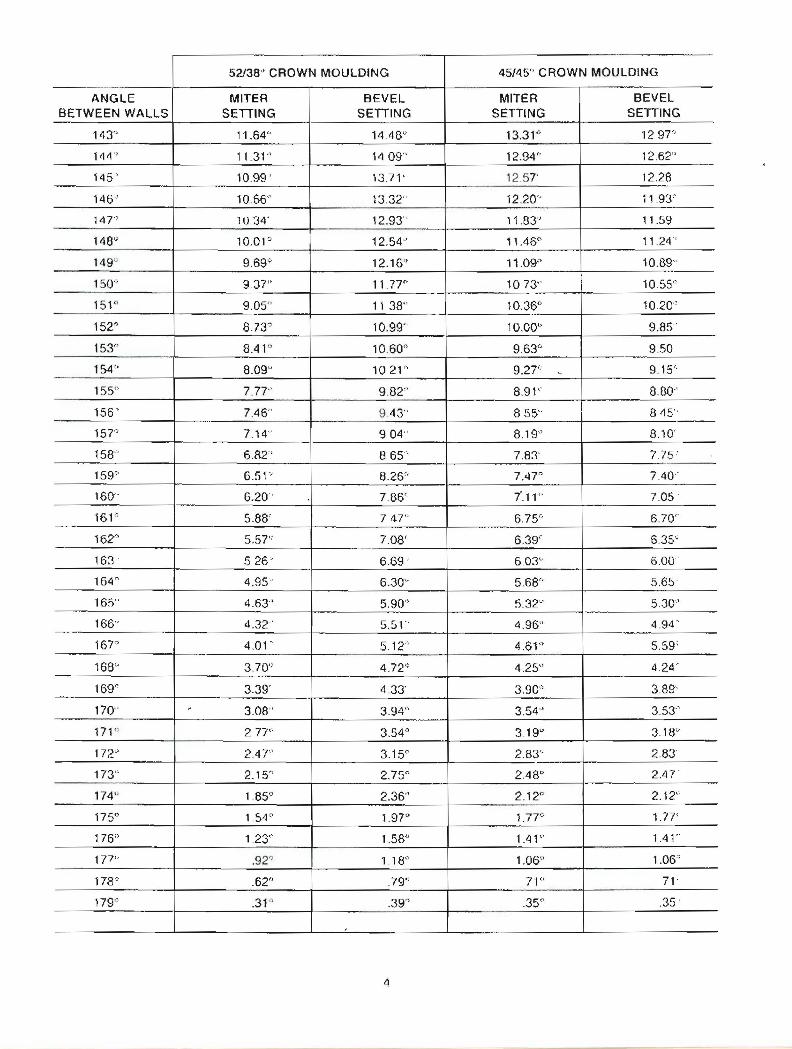
The following chart Illustrates the miter and bevel angle sellings of the saw blade for bolll 52/38 degree and 45/45 degree crown moulding, when the angle between the walls range from 67 degrees 10 179 degrees as shown IJYFig. 3
CEILING
Fig,l
Fig 2
Fig. :3

52138" CROWN MOULDING 45/45" CROWN MOULDING
ANGLE BETWEEN WALLS
MITER SETIING
BEVEL SETTING
MITER SEITING
BEVEL SETIING
67" 4293" 41,08" 4689' 36.13'"
68'" 4239" 40.79" 4635' 35.89'
69' 41,85" 4050 ' 4581 35.64"
70' 41,32 40,20' 45.28 35.40 .----_.._71' 40.79" 3990" 44.75 35 '5'
72" 40.28" 39.61" 44.22 34.89'
73 ' 39.76 3930" 43.70 34.6-4'
74' 39.25" 39,00" 43.18" 34,38'
75' 3874'" 38.69-' 42.66' 34.12"
76° 38.24 u 38.39~ 42,15 0 33.86'
77" 37.74" 38.08'" 41.64" 33.60"
78" 3724 . 37,76" 41.13 ' , 3333'
79 36,75' 3745" 40.62 33.07
80 36.27' 37.13' 40.12 32.80
81" 35.79" 36.81 . 39.62" 32.53
82 J 35.31° 36.49~_. 39,13" 32,25'
8T' 34.83' 36.1'1' 38.63' 31.98
84" 3'1,36" 35.85" 38.14" 31 70
85' 33,90' 35.52 37.66' 31.42'
86' 3343' 3519' 37.17' 31.14
87' 32.97" 34.86~ 3669(' 30,86-'
88' 32.52 34.53' 36.21 ' 30.57
89" 32.0"1" 34.20 . 35,74') 30.29
*90' *31.62" * 33.86' 35.26" 30.00'
91" 31.17" 33.53" 34 79~ 29.71 '
92° 30.73" 33.1gu 34.33u 29.42"
93" 30.30" 32.85" 3386 0 29.13"
94" ~ 29.86'-' 32.51 0 33.40,0 28.83'
95" 29.43" 321 T' 32,94" 28,54
96" 29.00" 31.82 3248-' 2824"
9?" 28.58" 31.48" 3202" 27,94'
98° 28.16° 31.13" 31,58" 27 6-4"
99~ 27.74" 30,78' 31.13 27.34'"
100" 27.32" 30.43' 30 68~ 27 ,O3~
10' 26.91' 30.08" 30 24~ 26,73"
102r. 26.50" 29.73" 29.80° 26.42'
103" 26.09" 29.38" 2936" 26,12
104" 2569" 29.02" 28.92" 2581'
* POSITIVE MITER STOP AND B17VEL INDICA10R PROVIDED ON FRAME & TRIM SAWS
TnIANGLE INDICATORS PROVIDED ON SCALES OF COMPOUND MITEn SAWS
2

52138 CROWN MOULDING 45/45" CROWN MOULDING -
ANGLE MITER BEVEL MITER BEVEL BETWEEN WALLS SETTING SETTING SETTING SETTING
105' 2529' 28.67' 28.48 25.50'
106 24.89" 28.31" 28.05' 25 19'
107 24 1\9 27.95" 2762' 2487'
108' 24.10 . 2759' 27.19' 24.56
109' 2371 27.23' 26.77' 24.21\
110 23.32 26.87 26.34 23.93
111 2293 26.51 25.92 I
2361
112 22.5~ 26.15 25.50 23.29 .~
113 22,17 25,78 ._, 2508 2297'
- 114 21.79 25.42 2<'\.66 22.65 .
lIS 21,42 25.05 24.25 2233
116 21 04 24.68' 23,84 22.01
117 20.67 I
24.31 23.43 2\.68 ~_. ...,
118 20.30 23.94 2302 21.36
119 19.93 23.57 2261 21 03
120 1957 23.20" 22,21" 2070 . 121 19.20 22.83 21,80 20.38
122 - 18,84 2246 21.40 2005 '
123' 18.48 22.09 21.00 . 19.72
124 ' 18.13 21.71 2061 19.39
125 17.77 21.34 2021 . 19.06
126' 1'7.'-12 20.96 19.81 18,72
127 17.06 2059 1942 18.39
128 1671 20.21 19.03 - ". 18.06
129 1637 1983 18.64 17,72
130' 1602 19.45 18.25 17.39
131 . 15.67 1907 . 17.86 17.05
132 - 1533 18.69' 1748' 16.71 .
133' 14.99 18.31' 17.09 1638
134' 14.65" 17,93" 16.71' 16.04
135" 14.30" 17,55 . 16.32 1570
136' 13,97'" 17.17" 1594 IS.3G
137" 13.63'" 16.79 15.56 15.02
138' 1330 c ' 16.40' 15.19 14.68
............,
139" 12.96" 16.020 14.81 . 14.34"
140' 12.63" 15.64" 1443" 1400
141" 12.30" 1525' 14.06 13.65
142' 11.97:' 14.B7" 136B' 1331 -
3
52138" CROWN MOULDING 45/45" CROWN MOULDING -----
ANGLE MITER BEVEL MITER BEVEL BETWEEN WALLS SETIING SETTING SETTING SETIING
143" , 1.64~ 14.48" 13.31'" '297"
144') 11.31" ~4 09" 12.94" 12.62" -145' 10.99 ' 13.71 ' 12.57' 12.28
146' 10.66" 13.32" 12.20" 11.93"
147" 1U.34· 12.93" 11,83" 11.59
148~ lO.OF 12.54~· 11.46" 1124"
149'-' 9,69'" 12.16" 11.09" 10.89"
150" 9.37" 11.77" 10 73" 1055"
151" 9.05" 11 38" 10.36" 10.20"
152? 8.73~ 10.99" 10.00" 9.85"
153" 8.41(' 10.60" 9.63" 950
154" 8.09" 1021" 927" , 9.15"
155" 7.77' 9.82" 8.91" 8.£30"
156' 7.46" --
9.'l3" 8,55" 81\5"
lsr 7.14' 904" 8.19" 8.10'
158" 6.82" 8 65" 7,83' 7.75-'
1590 65P 8.26" 7.'UO 7.40"
160" 6.20" 7.136' 1.11" 7.05'
161" 5.88' 747" 6,75" 6.70"
162" 5.57" 7.08' 6.39' 6.35" ~_.-
163" S 26 6.69' 603" 6.00'
164" 4.95'" 6.30~ 568" 5.65
165" 4.63" 5,90" 5.32~ - 530"
166" 4.32' 551' 4.96" 4.94"
16T' 4.01' 5.12' 4.61" 5,59'
168" 3,70'" 4.72" 4.25" 4.24"
169~ 3.39' 4.33' 3.90" 3,89'
170" - 3.08" 394" 3.54" 3.53'"
171') 277" 3.54° 3.19u 3.1W
172" 2.47" 3.15Q 2.83" 2.83"
173" 2.15 0 2.75" 2.48 D 2.47'
174'-' 1.85c 2.36" 2.12" 2.12"
175<> 1.54~ 1.97" 1.77" 1.77'
176" 1.23<' 1.58~ 1.41" 1.41"
177" .92" 1.18" 1.06" 1.06';
178' .62" .79" 71" 71'
179" .31" .390 .35<' .35 .
,
4