Embed Size (px)
Citation preview
CELLULAR CONFINEMENT SYSTEM RESEARCH JANUARY 25, 2006 CTSW-RT-06-137.20.1
State of California Department of Transportation Division of Environmental Analysis Stormwater Program 1120 N Street Sacramento, CA 95814 http://www.dot.ca.gov/hq/env/stormwater/index.htm
For individuals with sensory disabilities, this document is available in alternate formats upon request. Please call or write to Caltrans Division of Environmental Analysis, P.O. Box 942874, MS-27, Sacramento, CA 94274-0001. (916) 653-8896 Voice, or dial 711 to use a relay service..
Table of Contents
Executive Summary................................................................................................................... iv
Section 1 Introduction ......................................................................................................1-1
Section 2 New Technology Research..............................................................................2-1
2.1 Research Methods and Selection of New Technologies........................................2-1 2.2 Research Results....................................................................................................2-1 2.3 BMP Fact Sheet Description and Format ..............................................................2-3
2.3.1 BMP Comparison and Cost Effectiveness Summary ...............................2-3 2.3.2 Description................................................................................................2-3 2.3.3 Definition and Purpose .............................................................................2-4 2.3.4 Appropriate Applications..........................................................................2-4 2.3.5 Advantages................................................................................................2-4 2.3.6 Limitations ................................................................................................2-4 2.3.7 Effectiveness .............................................................................................2-4 2.3.8 Cost and Availability ................................................................................2-4 2.3.9 Key Design Elements................................................................................2-5 2.3.10 Materials ..................................................................................................2-5 2.3.11 Assembly, Installation, and Removal........................................................2-5 2.3.12 Maintenance and Inspection......................................................................2-5 2.3.13 Literature Sources .....................................................................................2-5
Section 3 References ........................................................................................................3-1
Section 4 Index ..................................................................................................................4-1
Section 5 Conclusion........................................................................................................5-1
Appendices
Appendix A Cellular Confinement System BMP Fact Sheets
ii
List of Acronyms and Abbreviations
BMP Best Management Practice CCS Cellular Confinement System DOT Department of Transportation ft feet ft/s feet per second ft2 square feet g/cc grams per cubic centimeter H horizontal HDPE High Density Polyethylene in inch lbs pounds m meter mil a unit of length 1/1000 inch long mm millimeter NS Non Storm Water SS Soil Stabilization SWMP Storm Water Management Plan TC Tracking Control V vertical
iii
Executive Summary
Caltrans has an ongoing program to evaluate new and developing technologies for storm water management. Erosion and sediment control practices and products are part of this evaluation. “New technologies” include practices and products that have recently been developed, as well as existing practices and products that have not been selected as Best Management Practices (BMPs) by Caltrans. The overall goal is to identify promising practices and products for future pilot studies. New practices and products will be recommended by Caltrans, as applicable, to new construction and maintenance projects. Favorable evaluations of promising BMP technologies can lead to pilot studies to gather cost and performance data. Once piloted technologies are successful, they may be approved and listed in the Department’s Storm Water Management Plan (SWMP) to be used according to the BMP implementation procedures.
The purpose of this document is to provide supporting information to construction staff on appropriate uses of Cellular Confinement Systems (CCS) as a temporary construction site BMP. Presented in the report are the results of research and investigation of existing literature, websites, and manufacturers to determine applicable uses of CCS as a temporary construction BMP. The results are presented in the form of BMP Fact Sheets for each CCS including descriptions, definitions, applications, advantages, limitations, costs, installation guidelines, and maintenance/inspection items. The Fact Sheets provided in Appendix A summarize information for technologies that are untested and unapproved by the Department.
CCS is widely recognized in the construction industry as a permanent soil stabilization BMP. The goal of this report is to identify potential uses for temporary applications. Results of the CCS research indicate that the most beneficial and cost effective uses of CCS as a temporary BMP are for ground stabilization of temporary stream crossings (as described in NS-4), temporary stabilized construction entrance/exit (TC-1) and temporary stabilized construction roadway (TC-2). Based on available data, use of CCS for slope and channel stabilization, and retaining walls entirely for temporary applications is typically not justified based on cost and time of installation. However, CCS could, in some cases, act preliminarily as a temporary BMP that transitions to a permanent capacity if identified as such on the project drawings and installed and maintained in the proper manner.
iv
SECTIONONE Introduction
SECTION 1 INTRODUCTION
Cellular Confinement Systems (CCS) are widely recognized in the construction industry as a permanent soil stabilization BMP used for a variety of applications including: erosion control and soil stabilization on steep slopes, revetments and flexible channel lining systems, roadway load support and stabilization, and earth retention structures. The goal of this report is to identify potential uses for temporary construction erosion and sediment control applications.
Typically, CCS panels or mats, also commonly referred to as “geocells,” consist of High Density Polyethylene (HDPE) strips ultrasonically bonded together to form a three-dimensional honeycomb matrix that can be filled with soil, sand, aggregate, or concrete. The relatively lightweight panels are shipped in a compact, collapsed form that are expanded at the job site. The panels typically come in a variety of cell sizes, and in perforated and non-perforated formats. Originally, geocell mats were developed by the United States Army Corps of Engineers (USACE) for building roads on soft and sandy soils. The USACE developed the first material testing guidelines for CCS in their Technical Report GL-86-19. Currently CCS is available through a number of proprietary distributors and is manufactured by a few companies, some of which manufacture the panels under patent license from USACE.
Section 2 of this report provides information on the method of research and selection of the products for which new BMP Fact Sheets were created. Section 3 of this report provides reference information used to prepare the fact sheets and Section 4 provides an index of the products for which fact sheets are provided. The BMP Fact Sheets are provided in Appendix A and summarize the results of the investigation and research of the various proprietary systems including descriptions, definitions, applications, advantages, limitations, costs, installation guidelines, and maintenance/inspection items.
1-1
SECTIONTWO New Technology Research
SECTION 2 NEW TECHNOLOGY RESEARCH
2.1 RESEARCH METHODS AND SELECTION OF NEW TECHNOLOGIES
Research methods for this report consisted of researching existing published reports, erosion control literature, vendor product manuals, and internet websites to determine manufacturers that produce CCS with distribution to California. The manufacturers and/or product representatives were contacted to obtain product information including: product description, pictures, appropriate applications (particularly temporary applications), limitations, key design elements, material specifications, installation guidelines, maintenance and inspection issues, availability, longevity, degradability, cost, and locations of previous installations on Caltrans jobs.
The Caltrans Erosion Control New Technology Report, CTSW-RT-03-049, provided fact sheets for Topsoiling with Cellular Confinement and several systems listed as CCS. However, some of these fact sheets were for revetment systems consisting of interlocking pre-cast concrete blocks (Tri-lock, Enviromat, Petraflex), porous pavement (Grasspave2), and geogrid (Tenax MS Geogrid). Precast concrete revetment, porous pavement, and geogrid systems were not considered as CCS for the current report because precast concrete block revetment and porous pavement systems are predominately permanent applications and are generally not considered as CCS. Geogrid systems such as Tenax MS Geogrid are also not typically considered CCS. The CTSW-RT-03-049 report did identify Tenax Tenweb as a permanent BMP CCS system, which was considered for this report to be a candidate temporary CCS BMP.
The products selected for evaluation include:
• Geoproducts – Envirogrid • Mirafi – Miraweb • Presto –Geoweb • Tenax – TenWeb • Webtec - TerraCell
2.2 RESEARCH RESULTS
The research results were concentrated on determining appropriate temporary construction site erosion control BMP applications for CCS. Research or literature data comparing the various products from an installation, maintenance, performance, and erosion control effectiveness standpoint was not located.
Results of the CCS research indicate that the most beneficial and cost effective uses of CCS are in conjunction with the following approved temporary construction site BMPs:
• Ground stabilization for temporary stream crossings (NS-4);
• Temporary stabilized construction entrance/exit (TC-1); and
• Temporary stabilized construction roadway (TC-2).
Use of CCS for typical temporary slope and channel erosion control stabilization and retaining wall applications is typically not justified based on the cost to install and remove CCS. CCS is typically more
2-1
SECTIONTWO New Technology Research
expensive to install than the most expensive Rolled Erosion Control Product (SS-7), even without considering removal costs of CCS. CCS could, in some cases, act in both temporary and permanent capacities if identified as such on the project drawings and installed and maintained in the proper manner. Caltrans design engineers and consultants should be aware that if a CCS system is to be used both in a temporary and permanent application in the same installation, it should be called out as such on the Water Pollution Control Drawings and the Project Construction Drawings, so that there is no confusion as to the status of the product (temporary versus permanent), since temporary erosion control products typically must be removed after the completion of construction.
Following is a partial list of locations where CCS was used on Caltrans projects (nearly all permanent applications used Presto Products Company Geoweb product except where noted). The list of permanent applications indicate that the product has been used numerous times on Caltrans jobs predominately for slope stabilization, channel protection, and retaining wall purposes.
Temporary Applications
• Highway 29 near Napa: Load support for 1995 seismic retrofit access road
Permanent Applications
• I-5 La Costa Avenue: Caltrans BMP Retrofit Pilot Program – La Costa Wet Basin maintenance access road
• Highway 1 near Laguna Beach: 1995 Fill Slope Stabilization and Channel Protection at Crystal Cove State Beach
• Highway 1 in Tomales: 1998 Drainage Swale
• Highway 1 near Watsonville: 1991 Slope Failure Repair.
• Highway 17 in Santa Cruz: 1992 Rock Slope Stabilization
• Highway 52 near San Diego: 1999 Slope Stabilization
• Highway 78 in San Marcos: 2000 Drainage Channel
• Highway 84 near Rio Vista: 1997 Rock Infilled Levee Slope Protection
• Highway 87 near San Jose: 1992 Steep Slope Repair
• Highway 101 near Santa Barbara: 2002 Costal Slide Repair
• Highway 101 near Santa Margarita: 1995 Retaining Wall System.
• Highway 144 near Santa Barbara: 2002 Slope Stabilization for landslide repair
• Highway 101 near Santa Barbara: 1997 Bridge Overcrossing Slope Protection
• Highway 152 on Hecker Pass: 1998 Vegetated Slope Protection
• 1996 Highway Patrol Transportation Management Center in Kearney Mesa
• Interstate 10 at Cherry Avenue in Fontana: Vegetated Slope Stabilization for erosion control (using Mirafi Miraweb product)
2-2
SECTIONTWO New Technology Research
• Interstate 580 near Pleasanton: Channel Stabilization. 1994 Rock infilled channel protection under bridge
• Interstate 580 in Richmond and Albany: Channel Stabilization. 1999 Albany Mudflat Reclamation.
• Interstate 980 near Oakland: Channel Stabilization. 1986 Median Drainage Swale Protection.
2.3 BMP FACT SHEET DESCRIPTION AND FORMAT
Each fact sheet presented in Appendix A is divided into a standard series of discussion topics, which are discussed below. The fact sheets are tailored after the fact sheets provided in the 2003 Caltrans Construction Site BMPs Manual, with additional information added for evaluating cost effectiveness and comparison to Department approved temporary construction site BMPs.
A summary CCS fact sheet is provided, which provides an overview of all the HDPE Cellular Confinement Systems contained in this report in addition to individual product fact sheets that provide product specific information on product description, materials, and installation guidelines.
2.3.1 BMP Comparison and Cost Effectiveness Summary
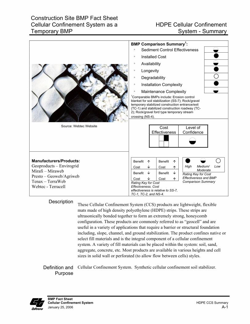
This section of the fact sheet provides a summary comparison between CCS and approved temporary erosion control BMPs used for similar applications. The similar BMPs include: rolled erosion control products for soil stabilization (SS-7); rock/gravel temporary stabilized construction entrance/exit (TC-1); stabilized construction roadway (TC-2); and rock/gravel ford type temporary stream crossing (NS-4). The rating key circles (full, half, empty circles) indicate the average relative rating of CCS to the comparable BMPs in the categories of: sediment control effectiveness, installed cost, availability, longevity, degradability, installation complexity, and maintenance complexity. Relative BMP comparison ratings are expressed in terms of High, Medium, and Low and are defined in the applicable sections below.
The cost effectiveness summary provides a graphical representation of a relative cost/benefit analysis of CCS used as a temporary BMP along with a rating of the level of confidence in the cost effectiveness rating. A four quadrant system was used as a tool to rate each BMP, and one of the four quadrants was colored based on the rating key provided in the fact sheet. The benefit/cost rating key provides a description of each of the blocks in the cost effectiveness table. The upper left block is best scenario (high benefit with low cost) and the lower right block is the worst scenario (low benefit with high cost). CCS used as a temporary BMP falls in the upper right block with relatively high benefits with associated relatively high cost. The level of confidence in the summary cost effectiveness rating is Medium to Low because installation cost is highly dependent upon site specific applications and also due to the lack of available data from manufacturers and for installation costs of CCS for temporary applications listed in the fact sheets.
2.3.2 Description
This section provides product specific descriptions obtained from manufacturer data sheets. The HDPE Cellular Confinement System Summary sheet provides an overall product description compiled from the individual product fact sheets.
2-3
SECTIONTWO New Technology Research
2.3.3 Definition and Purpose
The definition and purpose for each fact sheet is the same for each fact sheet and provides general information on the purpose of the cellular confinement system.
2.3.4 Appropriate Applications
This section provides a listing of the appropriate temporary construction site BMP application for CCS and is the same for each of the product fact sheets.
2.3.5 Advantages
This section lists the advantages of using CCS as a temporary construction site erosion control, soil stabilization and tracking control BMP and is the same for each of the product fact sheets.
2.3.6 Limitations
This section lists the limitations of using CCS as a temporary construction site erosion control, soil stabilization and tracking control BMP and is the same for each of the product fact sheets.
2.3.7 Effectiveness
This section lists the relative sediment control effectiveness of using CCS as a temporary construction site BMP compared to approved rolled erosion control products (SS-7), temporary stabilized construction entrance/exit (TC-1), temporary stabilized construction roadway (TC-2), and a gravel/rock ford type temporary stream crossing (NS-4). Relative ratings are expressed as High, Medium, and Low as follows:
• High: significantly enhanced sediment control effectiveness;
• Medium: approximately equivalent sediment control effectiveness; and
• Low: reduced sediment control effectiveness.
2.3.8 Cost and Availability
This section lists the relative cost and availability of using CCS as a temporary construction site BMP compared to the approved temporary BMPs listed in Section 2.3.7 using ratings of High, Medium, and Low. Cost comparisons are listed as:
• High: significantly increased material or installation cost compared to similar BMP applications;
• Medium: approximately equivalent material or installation cost compared to similar BMP applications; and
• Low: significantly reduced material or installation cost compared to similar BMP applications.
2-4
SECTIONTWO New Technology Research
Level of confidence in the cost effectiveness rating provided in the cover sheet summary.
Availability comparisons are listed as:
• High: typically available within one week;
• Medium: typically available within two to four weeks; and
• Low: typically available over four weeks.
2.3.9 Key Design Elements
This section identifies important design considerations that have been highlighted in manufacturer data sheets and literature.
2.3.10 Materials
This section presents manufacturer specific information on the material properties and testing methods used in the production of the product. Also included are dimensions of the product.
2.3.11 Assembly, Installation, and Removal
This section provides manufacturer specific information (or general installation guidance where manufacturer specific information was not available) on the assembly and installation of the product. Since these products are generally marketed as permanent soil stabilization and load support systems, documented manufacturer information was not available on system removal guidelines, however, general guidelines are provided based on manufacturer suggestions.
2.3.12 Maintenance and Inspection
This section provides general information on suggested maintenance and inspection guidelines compiled from manufacturer data sheets and Caltrans New Technology Fact Sheets provided in the 2003 Caltrans New Technology Report, CTSW-RT-03-049.
2.3.13 Literature Sources
This section provides the sources used to compile the information in the data sheet and includes manufacturer and Caltrans sources.
2-5
SECTIONTHREE References
SECTION 3 REFERENCES
1. Caltrans, 2003. Statewide Storm Water Management Plan. May 2003. CTSW-RT-03-008. http://www.dot.ca.gov/hq/env/stormwater/
2. Caltrans, 2002. Storm Water Planning and Design Guide. September 2002. http://ww.dot.ca.gov/hq/oppd/stormwtr/PPDG-stormwater-2002.pdf
3. Caltrans, 2003. Construction Site Best Management Practices Manual. March 2003. http://www.dot.ca.gov/hq/construc/stormwater/manuals.htm
4. Caltrans, 2004. Storm Water Treatment BMP Technology Report. November 2004. CTSW-RT-04-069.04.06. http://www.dot.ca.gov/hq/env/stormwater/special/newsetup/index.htm
5. Caltrans, 2003. Erosion Control New Technology Report, June 2003. CTSW-RT-03-049. http://www.dot.ca.gov/hq/env/stormwater/special/newsetup/index.htm
6. Santoni, Rosa L., and Tingle, Jeb S., 2002. United States Army Corps of Engineers, Army Engineer Research and Development Center. Building Roads on Soft and Sandy Soils. http://www.almc.army.mil/alog/issues/JanFeb02/MS698.htm
7. Salix Applied Earthcare, 2004. Erosion Draw Version 5.0 Software.
8. Geoproducts, Inc. (AGH Industries). http://www.envirogrid.com/ or http://www.geoproducts.org/index.html
9. Presto Geosystems. http://www.geo-synthetics.com/Geoweb_Cellular_Confinement_System.asp
10. Soil Stabilization Products Company, Inc. http://www.sspco.com
11. Soil Stabilization Products Company, Inc. 18 Years of Problem Solving with Caltrans.
12. Tenax. http://www.tenax.net/geosynthetics/products/tenax_tenweb.htm
13. Rimoldi, Pietro, et. al. Tenax SpA. Erosion Control: The Design with TENAX TENWEB geocells.
14. Webtec. http://www.webtecgeos.com/TerraCell/Tcell_RetWall/default.htm
15. Mirafi. http://www.tcmirafi.com/products/product_mweb.html
3-1
SECTIONFOUR Index
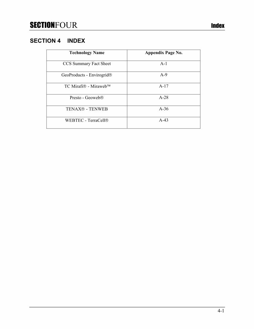
SECTION 4 INDEX
Technology Name Appendix Page No.
CCS Summary Fact Sheet A-1
GeoProducts - Envirogrid A-9
TC Mirafi - Miraweb A-17
Presto - Geoweb A-28
TENAX - TENWEB A-36
WEBTEC - TerraCell A-43
4-1
SECTIONFIVE Conclusion
SECTION 5 CONCLUSION
The most beneficial and cost effective temporary uses of CCS are in conjunction with the following approved temporary construction site BMPs:
• Ground stabilization for temporary stream crossings (NS-4);
• Temporary stabilized construction entrance/exit (TC-1); and
• Temporary stabilized construction roadway (TC-2).
Use of CCS for typical temporary slope and channel erosion control stabilization and retaining wall applications is typically not justified based on the cost to install and remove CCS. CCS could, in some cases, act in both temporary and permanent capacities if identified as such on the project drawings and installed and maintained in the proper manner. Following is a summary comparison of CCS versus comparable BMPs for temporary soil and ground stabilization applications:
• Relative installed cost compared to SS-7 (Rolled Erosion Control Products) is High;
• Relative installed cost compared to TC-1, TC-2, and NS-4 is Moderate to High;
• Relative sediment control effectiveness compared to SS-7 used in a temporary slope stabilization application is Low to Moderate;
• Relative ground stabilization effectiveness compared to TC-1, TC-2, and NS-4 is Moderate to High since CCS provides enhanced ground stabilization and load support while using less volume of aggregate material;
• Product availability, or delivery time, is Moderate (typically 2 to 4 weeks);
• Relative installation complexity compared to SS-7 is Moderate to High, and High compared to TC-1, TC-2, and NS-4; and
• Relative maintenance complexity is approximately the same as SS-7, TC-1, TC-2, and NS-4.
5-1

APPENDIXA BMP Fact Sheets
Construction Site BMP Fact Sheet Cellular Confinement System as a Temporary BMP
HDPE Cellular Confinement
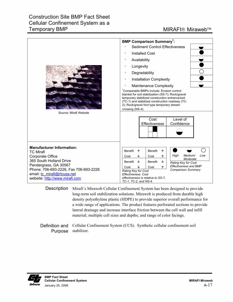
BMP Comparison Summary1: ° Sediment Control Effectiveness
° Installed Cost
° Availability
° Longevity
° Degradability
° Installation Complexity
° Maintenance Complexity 1Comparable BMPs include: Erosion control blanket for soil stabilization (SS-7); Rock/gravel temporary stabilized construction entrance/exit (TC-1) and stabilized construction roadway (TC-2); Rock/gravel ford type temporary stream crossing (NS-4).
Source: Webtec Website
Cost Effectiveness
Level of Confidence
Manufacturers/Products: Geoproducts – Envirogrid Mirafi – Miraweb Presto – Geoweb/Agriweb Tenax – TerraWeb Webtec - Terracell
Benefit
Cost
Benefit
Cost Benefit
Cost Benefit
Cost Rating Key for Cost Effectiveness. Cost effectiveness is relative to SS-7, TC-1, TC-2, and NS-4.
High Medium/ Low Moderate
Rating Key for Cost Effectiveness and BMP Comparison Summary
Description These Cellular Confinement System (CCS) products are lightweight, flexible mats made of high density polyethylene (HDPE) strips. These strips are ultrasonically bonded together to form an extremely strong, honeycomb configuration. These products are commonly referred to as “geocell” and are useful in a variety of applications that require a barrier or structural foundation including, slope, channel, and ground stabilization. The product confines native or select fill materials and is the integral component of a cellular confinement system. A variety of fill materials can be placed within the system: soil, sand, aggregate, concrete, etc. Most products are available in various heights and cell sizes in solid wall or perforated (to allow flow between cells) styles.
Definition and Purpose
Cellular Confinement System. Synthetic cellular confinement soil stabilizer.
System - Summary
BMP Fact Sheet Cellular Confinement System HDPE CCS Summary January 25, 2006 A-1
Construction Site BMP Fact Sheet Cellular Confinement System as a Temporary BMP
HDPE Cellular Confinement System - Summary
Appropriate Applications
■ Temporary Stream Crossing: Temporary ford type stream crossing in dry washes or ephemeral streams in arid areas during non-rainy season as described in NS-4. CCS are appropriate for streams that would benefit from an influx of gravel.
■ Ground stabilization, load support and tracking control at temporary stabilized construction entrance/exit, temporary construction access roads, and parking/storage areas.
■ Temporary slope stabilization, protection and revegetation on slopes (generally between 1V to 3H and 1V to 1H).
Advantages ■ Once expanded to its maximum extension and filled in with soil or gravel the CCS becomes inextensible and monolithic, providing an effective means of confinement for unconsolidated materials lying within single cells and preventing their movement even on steep slopes, or also from substantial dragging forces such as those exerted by sheet runoff.
■ Reduces runoff and sediment transport by confining soils within geocells. Cells are hydraulically interconnected and the CCS attains good permeability, facilitates the absorption of water during precipitation, diminishes surface runoff and consequently erosion.
■ Fords are the least expensive of the temporary stream crossing options outlined in NS-4. Relatively little rock or gravel is needed because the CCS provides the stability. For temporary fords, the CCS can be filled with natural river gravel, which may be a benefit to the stream upon removal of the CCS.
■ Improves soil structure and increases load support. Gravel/rock thickness may be reduced on temporary access road because CCS provides additional support. Use of a geocell can significantly reduce the amount and/or quality of aggregate required to stabilize a poor load bearing soil. If the temporary construction access road alignment is identical to a permanent roadway, use of the CCS may benefit the roadway section design. Note that use of CCS for both temporary and permanent applications at the same installation requires that it be designed accordingly and shown as such on both the Water Pollution Control Drawings and the Project Construction Drawings.
■ Possible alternative to removal/replacement of soft, poor soils along temporary access road routes and storage/parking areas.
■ Reduces formation of rills, gullies, and channels.
■ Lightweight and easy to transport.
■ For slope stabilization, CCS can be vegetated and thus serve both as a temporary and permanent BMP. CCS can minimize compaction and fill import. Note that use of CCS for both temporary and permanent soil stabilization BMP applications at the same installation requires that it be
BMP Fact Sheet Cellular Confinement System HDPE CCS Summary January 25, 2006 A-2
Construction Site BMP Fact Sheet Cellular Confinement System as a Temporary BMP
HDPE Cellular Confinement System - Summary
designed accordingly and shown as such on both the Water Pollution Control Drawings and the Project Construction Drawings. If it is not called out on the plans as a permanent soil stabilization BMP, construction site inspectors may call for its removal at completion of construction.
Limitations ■ For slope stabilization applications CCS are more expensive than other erosion control measures due to labor and material costs. Typically this system is used as a permanent slope soil stabilization BMP in areas where other BMPs are not appropriate.
■ Not suitable for temporary use as channel slope protection in channelized flow conditions with moderate to high velocities (greater than 4-6 ft/s), particularly when using soil infill. Permanent applications of CCS in channelized flow conditions may be acceptable when appropriately designed.
■ Not suitable for temporary ford type stream crossings during rainy season or in perennial streams. CCS must be removed from stream upon completion of construction.
■ Not to be used on solid rock slopes. Maximum slope 1V to 1H.
■ Fill material within cells may be washed out in steep slope application if temporary cover with an SS-7 Rolled Erosion Control Product is not provided.
■ Erosion control effectiveness is highly dependent upon proper installation. Requires proper pins and anchors to secure in place. If there is a long slope upstream, a diversion ditch is recommend upslope of the CCS.
■ Typically it is not cost effective to reuse CCS since the majority of the installation cost consists of equipment and labor.
Effectiveness ■ Relative effectiveness compared to SS-7 (Rolled Erosion Control Products) used in a temporary slope stabilization application is Low to Moderate, since an interim SS-7 product is typically required to cover the CCS soil until vegetation is established.
■ Relative effectiveness compared to temporary stabilized construction entrance/exit (TC-1) and stabilized construction roadway (TC-2) is Moderate to High, since the CCS provides enhanced ground stabilization and load support while using less volume of aggregate fill material.
■ Relative effectiveness compared to a gravel/rock ford type temporary stream crossing per NS-4 is Moderate to High since the CCS provides enhanced stability with less gravel/rock material.
BMP Fact Sheet Cellular Confinement System HDPE CCS Summary January 25, 2006 A-3
Construction Site BMP Fact Sheet Cellular Confinement System as a Temporary BMP
HDPE Cellular Confinement System - Summary
Cost and
Availability ■ Relative installed cost compared to SS-7 (Rolled Erosion Control Products) is
Moderate to High. Relative cost is High compared to biodegradible rolled erosion control products and Moderate to High compared to non-biodegradible erosion control products.
■ Relative installed cost compared to TC-1 is Moderate and to TC-2 is Moderate to High. However, cost savings may be realized, and relative costs low, if use of CCS eliminates the need for removal and replacement of poor soils.
■ Relative installed cost compared to rock/gravel ford type temporary stream crossing per NS-4 is Moderate.
■ Material Cost is Medium to High: Material costs range from approximately $1.00 - $2.50/ft2 for 3- to 8-inch deep standard size cells. Costs range from approximately $0.70 - $1.6/ft2 for 3- to 8-inch deep large size cells.
■ Production Rate/Installation Cost is High: Approximately $1.0 to 1.80/ft2
($45,000 - $78,000 per acre) for a typical slope protection or load support application using 3 to 4 inch deep cells. Installed costs of CCS is highly dependent on site conditions, project size, and local costs of infill materials, equipment, and labor.
■ Product availability, or delivery time, is Moderate (typically 2 to 4 weeks).
Standards and Specifications
Key Design Elements
■ Determine if use is temporary only or both temporary and permanent.
■ Determine temporary application type and compare to other systems and materials based on site conditions to determine most cost effective system that provides the required amount of erosion protection.
■ Stability analysis for slope applications.
■ Required thickness or depth of CCS.
■ Required site preparation and requirement for geotextile underlay/overlay.
■ Hydraulic flow condition (sheet flow or channelized flow and expected flow velocities). Determine if upstream areas will contribute concentrated flow to CCS.
■ Infill material (soil or gravel).
■ Anchor pin spacing and anchoring system.
BMP Fact Sheet Cellular Confinement System HDPE CCS Summary January 25, 2006 A-4
Construction Site BMP Fact Sheet Cellular Confinement System as a Temporary BMP
HDPE Cellular Confinement System - Summary
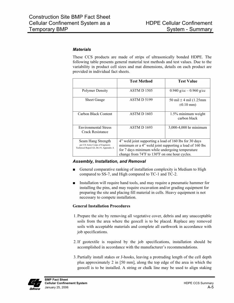
Materials
These CCS products are made of strips of ultrasonically bonded HDPE. The following table presents general material test methods and test values. Due to the variability in product cell sizes and mat dimensions, details on each product are provided in individual fact sheets.
Test Method Test Value
Polymer Density ASTM D 1505 0.940 g/cc – 0.960 g/cc
Sheet Gauge ASTM D 5199 50 mil ± 4 mil (1.25mm ±0.10 mm)
Carbon Black Content ASTM D 1603 1.5% minimum weight carbon black
Environmental Stress Crack Resistance
ASTM D 1693 3,000-4,000 hr minimum
Seam Hang Strength per US Army Corps of Engineers
Technical Report GL-86-19, Appendix A
4” weld joint supporting a load of 160 lbs for 30 days minimum or a 4” weld joint supporting a load of 160 lbs for 7 days minimum while undergoing temperature change from 74oF to 130oF on one hour cycles.
Assembly, Installation, and Removal
■ General comparative ranking of installation complexity is Medium to High compared to SS-7, and High compared to TC-1 and TC-2.
■ Installation will require hand tools, and may require a pneumatic hammer for installing the pins, and may require excavation and/or grading equipment for preparing the site and placing fill material in cells. Heavy equipment is not necessary to compete installation.
General Installation Procedures
1. Prepare the site by removing all vegetative cover, debris and any unacceptable soils from the area where the geocell is to be placed. Replace any removed soils with acceptable materials and complete all earthwork in accordance with job specifications.
2. If geotextile is required by the job specifications, installation should be accomplished in accordance with the manufacturer’s recommendations.
3. Partially install stakes or J-hooks, leaving a protruding length of the cell depth plus approximately 2 in [50 mm], along the top edge of the area in which the geocell is to be installed. A string or chalk line may be used to align staking
BMP Fact Sheet Cellular Confinement System HDPE CCS Summary January 25, 2006 A-5
Construction Site BMP Fact Sheet Cellular Confinement System as a Temporary BMP
HDPE Cellular Confinement System - Summary
locations and borders.
4. Geocell sections should be stretched past the designed length then allowed to settle back to the designed length. Set the end cells of the geocell sections over the previously installed stakes and complete installation of the stakes or J-hooks flush with or slightly below cell walls.
5. Adjoining sections must be level and flush with each other. Overlap the sides of the geocell sections and butt the ends together. Secure adjoining sections to each other using a pneumatic stapler, hot rings or other means as required by the job specifications.
6. Install the balance of the stakes or J-hooks as required by the job specifications.
7. When the geocells have been properly laid into place, the system should be infilled using the materials specified in the job specifications.
8. To prevent possible damage to the system, limit the drop height of the infill to no more than 3 ft [1 m].
9. When using sand, granular or top soil fills, overfill the geocell sections by 1 - 2 in [25 - 50 mm] to allow for settling and compaction.
10. Sand and granular fills should then be blade compacted to the top of the cells. Top soil fills should be compacted with the loader or back hoe or with a tamper plate. Concrete fills should be manually raked and machine finished.
Anchoring
The number and type of anchors is determined by subgrade density, weight and type of infill, slope grade and environmental conditions. Anchors should be left in place after installation. Systems with a low to moderate loading should be anchored using ”J” hooks or wooden stakes. Sites with severe conditions require further reinforcement. Anchoring the geocell with three or five tendons per section on slope grades up to 1:1 has been utilized with good success. The anchoring system utilizing tendons and “J” hooks should be set deep enough to reach a solid subbase. If the slope subbase is soft or porous, the anchoring system must be set very deep in order to hold the installation in place. The holes for tendons, which are drilled lengthwise in the collapsed form, may be drilled in the field before installation or during the manufacturing process. The tendon material should have a tensile strength sufficient to support the total theoretical load, and should be constructed of cable or creep resistant woven polyester. Before selecting the anchoring method, it is necessary to calculate the sliding force, or the force, which has to be overcome to keep the geocell from sliding or moving. If
BMP Fact Sheet Cellular Confinement System HDPE CCS Summary January 25, 2006 A-6
Construction Site BMP Fact Sheet Cellular Confinement System as a Temporary BMP
HDPE Cellular Confinement System - Summary
the sliding force is negative, then the friction between the geocell and slope is sufficient to hold the system in place.
Staking the geocell to a slope is the most common anchoring method used if there is no geomembrane present and if the soil has adequate strength to retain the stakes. Steel reinforcing bars bent into a “candy cane shape called J-hooks are the preferred type of stake. General Rule: the length of the stake should be three times the cell height.
If conditions require that adjacent sections of the geocell be joined together rather than butted against each other, hog rings or staples can be used. Staples are normally attached using a pneumatic staple gun with industrial grade staples. The staples or rings are attached through each set of adjoining cells.
Tendons are used on steep slopes when additional support is needed, or where the use of stakes is prohibited (such as a rock base or a geomembrane liner). They are also used when more than one section of a geocell is needed to cover a slope from top to bottom. The three important characteristics of tendons are strength, resistance to elongation and durability. The design load and spacing of the tendons is determined by the force to be supported. A large number of lighter tendons is preferable to a smaller number of heavier tendons. Batten strips or large washers at the bottom of the lowest section of the geocell are necessary to avoid stress concentrations. Sometimes it is necessary to pre-stretch and open the geocell prior to placing it on a slope. This is especially true if part or all of a section is going under water. In most cases an installation frame can be built from common lumber, PVC, and rebar.
Removal Removal of the system requires removal of the pins and anchoring system. Typically it is easier to install a new system than remove and re-use an existing system.
Maintenance and Inspection
■ Maintenance and inspection level of effort is Medium
■ Inspect weekly in winter for slope instability. Typically, redirect water from rills, fill rills with soil, compact soil in cells, and secure with erosion control blanket or top with mulch if necessary. Inspect anchoring system at top and toe, pins, erosion of material from the cells.
BMP Fact Sheet Cellular Confinement System HDPE CCS Summary January 25, 2006 A-7
Construction Site BMP Fact Sheet Cellular Confinement System as a Temporary BMP
HDPE Cellular Confinement System - Summary
Literature Sources ■ http://www.tenax.net/geosynthetics/products/tenax_tenweb.htm
■ http://www.mirafi.com
■ http://www.geoproducts.org
■ http://www.webtecgeos.com/TerraCell/default.htm
■ http://www.alcoa.com/alcoa_consumer_products/prestogeo/en/solutions/Geoweb_specifications.asp
■ Salix Applied Earthcare. Erosion Draw Version 5.0 Software, 2004.
■ Caltrans, 2003. Caltrans Erosion Control New Technology Report, CTSW-RT-03-049.
■ Caltrans, 2002. Project Planning and Design Guide.
BMP Fact Sheet Cellular Confinement System HDPE CCS Summary January 25, 2006 A-8

Construction Site BMP Fact Sheet Cellular Confinement System as a Temporary BMP
Geo Products Envirogrid
BMP Comparison Summary1: ° Sediment Control Effectiveness
° Installed Cost
° Availability
° Longevity
° Degradability
° Installation Complexity
° Maintenance Complexity 1Comparable BMPs include: Erosion control blanket for soil stabilization (SS-7); Rock/gravel temporary stabilized construction entrance/exit (TC-1) and stabilized construction roadway (TC-2); Rock/gravel ford type temporary stream crossing (NS-4).
Source: Envirogrid Website
Cost Effectiveness
Level of Confidence
Manufacturer Information: GeoProducts 8615 Golden Spike Lane Houston, Texas 77086 Phone:281-820-5493, Fax 281-820-5499 email: [email protected] websites: http://www.geoproducts.org http://www.envirogrid.com
Benefit
Cost
Benefit
Cost Benefit
Cost Benefit
Cost Rating Key for Cost Effectiveness. Cost effectiveness is relative to SS-7, TC-1, TC-2, and NS-4.
High Medium/ Low Moderate
Rating Key for Cost Effectiveness and BMP Comparison Summary
Description Distributed as GeoProducts Cellular Confinement System and Envirogrid. The geocell is a lightweight, expandable confinement system which creates an erosion barrier or structural foundation. This HDPE system slows down hydraulic energy, limiting forces within or under cells. The geocell is useful in a variety of applications that require a barrier or structural foundation including, slope, channel, and ground stabilization.
Definition and Purpose
Cellular Confinement System (CCS). Synthetic cellular confinement soil stabilizer.
BMP Fact Sheet Cellular Confinement System Geo Products Envirogrid January 25, 2006 A-9
Construction Site BMP Fact Sheet Cellular Confinement System as a Temporary BMP
Geo Products Envirogrid
Appropriate Applications
■ Temporary Stream Crossing: Temporary ford type stream crossing in dry washes or ephemeral streams in arid areas during non-rainy season as described in NS-4. CCS are appropriate for streams that would benefit from an influx of gravel.
■ Ground stabilization.
■ Load support and tracking control at temporary stabilized construction entrance/exit, temporary construction access roads, and parking/storage areas.
■ Temporary slope stabilization, protection and revegetation (generally between 1V to 3H and 1V to 1H).
Advantages ■ Once expanded to its maximum extension and filled in with soil or gravel the CCS becomes inextensible and monolithic, providing an effective means of confinement for unconsolidated materials lying within single cells and preventing their movement even on steep slopes, or also from substantial dragging forces such as those exerted by sheet runoff.
■ Reduces runoff and sediment transport by confining soils within geocells. All cells are hydraulically interconnected and the CCS attains good permeability, facilitates the absorption of water during precipitation, diminishes surface runoff and consequently erosion.
■ Fords are the least expensive of the temporary stream crossing options outlined in NS-4. Relatively little rock or gravel is needed because the CCS provides the stability. For temporary fords, the CCS can be filled with natural river gravel, which may be a benefit to the stream upon removal of the CCS.
■ Improves soil structure and increases load support. Gravel/rock thickness may be reduced on temporary access road because CCS provides additional support. Use of a geocell can significantly reduce the amount and/or quality of aggregate required to stabilize a poor load bearing soil. If the temporary construction access road alignment is identical to a permanent roadway, use of the CCS may benefit the roadway section design. Note that use of CCS for both temporary and permanent applications at the same installation requires that it be designed accordingly and shown as such on both the Water Pollution Control Drawings and the Project Construction Drawings.
■ Possible alternative to removal/replacement of soft, poor soils along temporary access road routes and storage/parking areas.
■ Reduces formation of rills, gullies, and channels.
■ Lightweight and easy to transport.
■ For slope stabilization, CCS can be vegetated and thus serve both as a temporary and permanent BMP. Can minimize compaction and fill import. Note that use of CCS for both temporary and permanent soil stabilization
BMP Fact Sheet Cellular Confinement System Geo Products Envirogrid January 25, 2006 A-10
Construction Site BMP Fact Sheet Cellular Confinement System as a Temporary BMP
Geo Products Envirogrid
BMP applications at the same installation requires that it be designed accordingly and shown as such on both the Water Pollution Control Drawings and the Project Construction Drawings. If it is not called out on the plans as a permanent soil stabilization BMP, construction site inspectors may call for its removal at completion of construction.
Limitations ■ For slope stabilization applications CCS are more expensive than other erosion control measures due to labor and material costs. Typically this system is used as a permanent slope soil stabilization BMP in areas where other BMPs are not appropriate.
■ Not suitable for temporary use as channel slope protection in channelized flow conditions with moderate to high velocities (greater than 4-6 ft/s), particularly when using soil infill. Permanent applications of CCS in channelized flow conditions may be acceptable when appropriately designed.
■ Not suitable for temporary ford type stream crossings during rainy season or in perennial streams. CCS must be removed from stream upon completion of construction.
■ Not to be used on solid rock slopes. Maximum slope 1V to 1H.
■ Fill material within cells may be washed out in steep slope application if temporary cover with an SS-7 Rolled Erosion Control Product is not provided.
■ Erosion control effectiveness is highly dependent upon proper installation. Requires proper pins and anchors to secure in place. If there is a long slope upstream, a diversion ditch is recommend upslope of the CCS.
■ Typically it is not cost effective to reuse CCS since the majority of the installation cost consists of equipment and labor.
Effectiveness ■ Relative effectiveness compared to SS-7 (Rolled Erosion Control Products) used in a temporary slope stabilization application is Low to Moderate, since an interim SS-7 product is typically required to cover the CCS soil until vegetation is established.
■ Relative effectiveness compared to temporary stabilized construction entrance/exit (TC-1) and stabilized construction roadway (TC-2) is Moderate to High, since the CCS provides enhanced ground stabilization and load support while using less volume of aggregate fill material.
■ Relative effectiveness compared to a gravel/rock ford type temporary stream crossing per NS-4 is Moderate to High since the CCS provides enhanced stability with less gravel/rock material.
BMP Fact Sheet Cellular Confinement System Geo Products Envirogrid January 25, 2006 A-11
Construction Site BMP Fact Sheet Cellular Confinement System as a Temporary BMP
Geo Products Envirogrid
Cost and Availability
■ Relative installed cost compared to SS-7 (Rolled Erosion Control Products) is Moderate to High. Relative cost is high compared to biodegradible rolled erosion control products and Moderate to High compared to non-biodegradible erosion control products.
■ Relative installed cost compared to TC-1 is Medium and to TC-2 is Moderate to High. However, cost savings may be realized, and relative costs low, if use of CCS eliminates the need for removal and replacement of poor soils.
■ Relative installed cost compared to rock/gravel ford type temporary stream crossing per NS-4 is Moderate.
■ Production Rate/Installation Cost is High: $1.00 - $1.80/ft2 ($45,000 - $78,000 per acre) for a typical slope protection or load support application using 3- to 4-inch deep cells. Installed costs of CCS is highly dependent on site conditions, project size, and local costs of infill materials, equipment, and labor.
■ Product availability, or delivery time, is Moderate (typically one week).
Standards and Specifications
Key Design Elements
■ Determine if use is temporary only or both temporary and permanent.
■ Determine temporary application type and compare to other systems and materials based on site conditions to determine most cost effective system that provides the required amount of erosion protection.
■ Stability analysis for slope applications.
■ Required thickness or depth of CCS.
■ Required site preparation and requirement for geotextile underlay/overlay.
■ Hydraulic flow condition (sheet flow or channelized flow and expected flow velocities). Determine if upstream areas will contribute concentrated flow to CCS.
■ Infill material (soil or gravel).
■ Anchor pin spacing and anchoring system.
Materials
The polymer used to manufacture the geocell shall be virgin, non-thermally degraded polyethylene which is clean and free of any contaminants. The manufactured geocell shall conform to property requirements listed and shall be free of defects including tears, nodules or any other defect that would affect its serviceability.
BMP Fact Sheet Cellular Confinement System Geo Products Envirogrid January 25, 2006 A-12
Construction Site BMP Fact Sheet Cellular Confinement System as a Temporary BMP
Geo Products Envirogrid
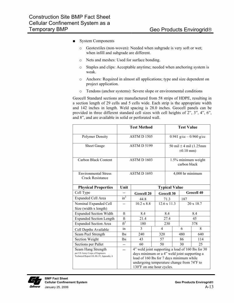
■ System Components
o Geotextiles (non-woven): Needed when subgrade is very soft or wet; when infill and subgrade are different.
o Nets and meshes: Used for surface bonding.
o Staples and clips: Acceptable anytime; needed when anchoring system is weak.
o Anchors: Required in almost all applications; type and size dependent on project application.
o Tendons (anchor systems): Severe slope or environmental conditions
Geocell Standard sections are manufactured from 58 strips of HDPE, resulting in a section length of 29 cells and 5 cells wide. Each strip is the appropriate width and 142 inches in length. Weld spacing is 28.0 inches. Geocell panels can be provided in three different standard cell sizes with cell heights of 2”, 3”, 4”, 6”, and 8”, and are available in solid or perforated wall.
Test Method Test Value
Polymer Density ASTM D 1505 0.941 g/cc – 0.960 g/cc
Sheet Gauge ASTM D 5199 50 mil ± 4 mil (1.25mm ±0.10 mm)
Carbon Black Content ASTM D 1603 1.5% minimum weight carbon black
Environmental Stress Crack Resistance
ASTM D 1693 4,000 hr minimum
Physical Properties Unit Typical Value Cell Type -- Geocell 20 Geocell 30 Geocell 40 Expanded Cell Area in2 44.8 71.3 187 Nominal Expanded Cell Size (width x length)
-- 10.2 x 8.8 12.6 x 11.3 20 x 18.7
Expanded Section Width ft 8.4 8.4 8.4 Expanded Section Length ft 21.4 27.4 45 Expanded Section Area ft2 180 230 378 Cell Depths Available in 3 4 6 8 Seam Peel Strength lbs 240 320 480 640 Section Weight lbs 43 57 86 114 Sections per Pallet -- 60 50 30 25 Seam Hang Strength per US Army Corps of Engineers Technical Report GL-86-19, Appendix A
-- 4” weld joint supporting a load of 160 lbs for 30 days minimum or a 4” weld joint supporting a load of 160 lbs for 7 days minimum while undergoing temperature change from 74oF to 130oF on one hour cycles.
BMP Fact Sheet Cellular Confinement System Geo Products Envirogrid January 25, 2006 A-13
Construction Site BMP Fact Sheet Cellular Confinement System as a Temporary BMP
Geo Products Envirogrid
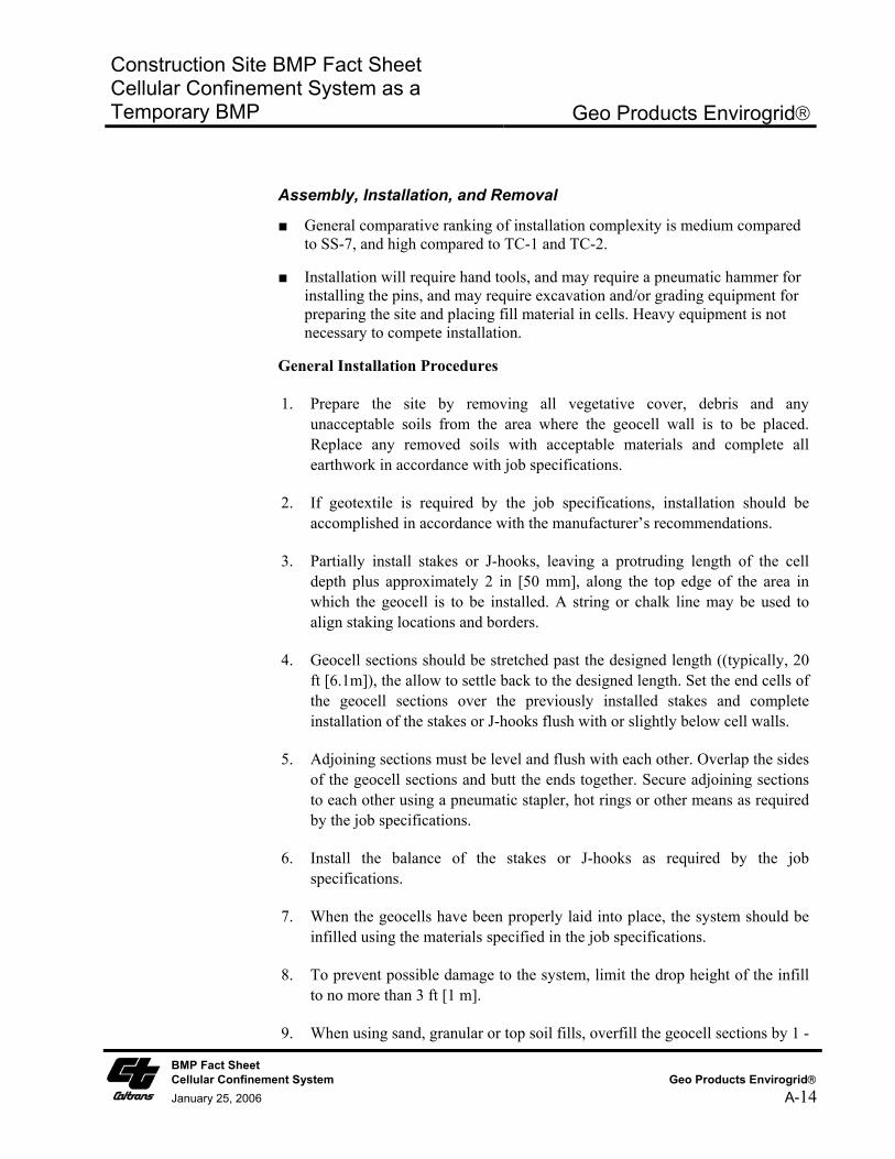
Assembly, Installation, and Removal
■ General comparative ranking of installation complexity is medium compared to SS-7, and high compared to TC-1 and TC-2.
■ Installation will require hand tools, and may require a pneumatic hammer for installing the pins, and may require excavation and/or grading equipment for preparing the site and placing fill material in cells. Heavy equipment is not necessary to compete installation.
General Installation Procedures
1. Prepare the site by removing all vegetative cover, debris and any unacceptable soils from the area where the geocell wall is to be placed. Replace any removed soils with acceptable materials and complete all earthwork in accordance with job specifications.
2. If geotextile is required by the job specifications, installation should be accomplished in accordance with the manufacturer’s recommendations.
3. Partially install stakes or J-hooks, leaving a protruding length of the cell depth plus approximately 2 in [50 mm], along the top edge of the area in which the geocell is to be installed. A string or chalk line may be used to align staking locations and borders.
4. Geocell sections should be stretched past the designed length ((typically, 20 ft [6.1m]), the allow to settle back to the designed length. Set the end cells of the geocell sections over the previously installed stakes and complete installation of the stakes or J-hooks flush with or slightly below cell walls.
5. Adjoining sections must be level and flush with each other. Overlap the sides of the geocell sections and butt the ends together. Secure adjoining sections to each other using a pneumatic stapler, hot rings or other means as required by the job specifications.
6. Install the balance of the stakes or J-hooks as required by the job specifications.
7. When the geocells have been properly laid into place, the system should be infilled using the materials specified in the job specifications.
8. To prevent possible damage to the system, limit the drop height of the infill to no more than 3 ft [1 m].
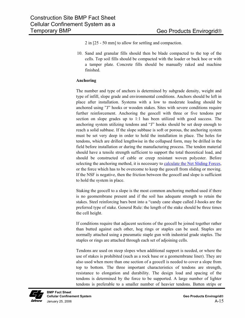
9. When using sand, granular or top soil fills, overfill the geocell sections by 1 -
BMP Fact Sheet Cellular Confinement System Geo Products Envirogrid January 25, 2006 A-14
Construction Site BMP Fact Sheet Cellular Confinement System as a Temporary BMP
Geo Products Envirogrid
2 in [25 - 50 mm] to allow for settling and compaction.
10. Sand and granular fills should then be blade compacted to the top of the cells. Top soil fills should be compacted with the loader or back hoe or with a tamper plate. Concrete fills should be manually raked and machine finished.
Anchoring
The number and type of anchors is determined by subgrade density, weight and type of infill, slope grade and environmental conditions. Anchors should be left in place after installation. Systems with a low to moderate loading should be anchored using ”J” hooks or wooden stakes. Sites with severe conditions require further reinforcement. Anchoring the geocell with three or five tendons per section on slope grades up to 1:1 has been utilized with good success. The anchoring system utilizing tendons and “J” hooks should be set deep enough to reach a solid subbase. If the slope subbase is soft or porous, the anchoring system must be set very deep in order to hold the installation in place. The holes for tendons, which are drilled lengthwise in the collapsed form, may be drilled in the field before installation or during the manufacturing process. The tendon material should have a tensile strength sufficient to support the total theoretical load, and should be constructed of cable or creep resistant woven polyester. Before selecting the anchoring method, it is necessary to calculate the Net Sliding Forces, or the force which has to be overcome to keep the geocell from sliding or moving. If the NSF is negative, then the friction between the geocell and slope is sufficient to hold the system in place.
Staking the geocell to a slope is the most common anchoring method used if there is no geomembrane present and if the soil has adequate strength to retain the stakes. Steel reinforcing bars bent into a “candy cane shape called J-hooks are the preferred type of stake. General Rule: the length of the stake should be three times the cell height.
If conditions require that adjacent sections of the geocell be joined together rather than butted against each other, hog rings or staples can be used. Staples are normally attached using a pneumatic staple gun with industrial grade staples. The staples or rings are attached through each set of adjoining cells.
Tendons are used on steep slopes when additional support is needed, or where the use of stakes is prohibited (such as a rock base or a geomembrane liner). They are also used when more than one section of a geocell is needed to cover a slope from top to bottom. The three important characteristics of tendons are strength, resistance to elongation and durability. The design load and spacing of the tendons is determined by the force to be supported. A large number of lighter tendons is preferable to a smaller number of heavier tendons. Batten strips or
BMP Fact Sheet Cellular Confinement System Geo Products Envirogrid January 25, 2006 A-15
Construction Site BMP Fact Sheet Cellular Confinement System as a Temporary BMP
Geo Products Envirogrid
large washers at the bottom of the lowest section of the geocell are necessary to avoid stress concentrations. Sometimes it is necessary to pre-stretch and open the geocell prior to placing it on a slope. This is especially true if part or all of a section is going under water. In most cases an installation frame can be built from common lumber, PVC and rebar.
Removal Removal of the system requires removal of the pins and anchoring system. Typically it is easier to install a new system than remove and re-use an existing system.
Maintenance and Inspection
■ Maintenance and inspection level of effort is Medium.
■ Inspect weekly in winter for slope instability. Typically, redirect water from rills, fill rills with soil, compact soil in cells, and secure with erosion control blanket or top with mulch if necessary. Inspect anchoring system at top and toe, pins, erosion of material from the cells.
Literature Sources ■ Caltrans, 2003. Caltrans Erosion Control New Technology Report, CTSW-RT-03-049.
■ Caltrans, 2002. Project Planning and Design Guide.
BMP Fact Sheet Cellular Confinement System Geo Products Envirogrid January 25, 2006 A-16
Construction Site BMP Fact Sheet Cellular Confinement System as a Temporary BMP
MIRAFI Miraweb
BMP Comparison Summary1: ° Sediment Control Effectiveness
° Installed Cost
° Availability
° Longevity
° Degradability
° Installation Complexity
° Maintenance Complexity 1Comparable BMPs include: Erosion control blanket for soil stabilization (SS-7); Rock/gravel temporary stabilized construction entrance/exit (TC-1) and stabilized construction roadway (TC-2); Rock/gravel ford type temporary stream crossing (NS-4).
Source: Mirafi Website
Cost Effectiveness
Level of Confidence
Manufacturer Information: TC Mirafi Corporate Office 365 South Holland Drive Pendergrass, GA 30567 Phone: 706-693-2226, Fax 706-693-2226 email: [email protected] website: http://www.mirafi.com
Benefit
Cost
Benefit
Cost Benefit
Cost Benefit
Cost Rating Key for Cost Effectiveness. Cost effectiveness is relative to SS-7, TC-1, TC-2, and NS-4.
High Medium/ Low Moderate
Rating Key for Cost Effectiveness and BMP Comparison Summary
Description Mirafi’s Miraweb Cellular Confinement System has been designed to provide long-term soil stabilization solutions. Miraweb is produced from durable high density polyethylene plastic (HDPE) to provide superior overall performance for a wide range of applications. The product features perforated sections to provide lateral drainage and increase interface friction between the cell wall and infill material; multiple cell sizes and depths; and range of color facings.
Definition and Purpose
Cellular Confinement System (CCS). Synthetic cellular confinement soil stabilizer.
BMP Fact Sheet Cellular Confinement System MIRAFI Miraweb
January 25, 2006 A-17
Construction Site BMP Fact Sheet Cellular Confinement System as a Temporary BMP
MIRAFI Miraweb
Appropriate Applications
■ Temporary Stream Crossing: Temporary ford type stream crossing in dry washes or ephemeral streams in arid areas during non-rainy season as described in NS-4. CCS are appropriate for streams that would benefit from an influx of gravel.
■ Ground stabilization, load support and tracking control at temporary stabilized construction entrance/exit, temporary construction access roads, and parking/storage areas.
■ Temporary slope stabilization, protection and revegetation on slopes (generally between 1V to 3H and 1V to 1H).
Advantages ■ Once expanded to its maximum extension and filled in with soil or gravel the CCS becomes inextensible and monolithic, providing an effective means of confinement for unconsolidated materials lying within single cells and preventing their movement even on steep slopes, or also from substantial dragging forces such as those exerted by sheet runoff.
■ Reduces runoff and sediment transport by confining soils within geocells. All cells are hydraulically interconnected and the CCS attains good permeability, facilitates the absorption of water during precipitation, diminishes surface runoff and consequently erosion.
■ Fords are the least expensive of the temporary stream crossing options outlined in NS-4. Relatively little rock or gravel is needed because the CCS provides the stability. For temporary fords, the CCS can be filled with natural river gravel, which may be a benefit to the stream upon removal of the CCS.
■ Improves soil structure and increases load support. Gravel/rock thickness may be reduced on temporary access road because CCS provides additional support. Use of a geocell can significantly reduce the amount and/or quality of aggregate required to stabilize a poor load bearing soil. If the temporary construction access road alignment is identical to a permanent roadway, use of the CCS may benefit the roadway section design. Note that use of CCS for both temporary and permanent applications at the same installation requires that it be designed accordingly and shown as such on both the Water Pollution Control Drawings and the Project Construction Drawings.
■ Possible alternative to removal/replacement of soft, poor soils along temporary access road routes and storage/parking areas.
■ Reduces formation of rills, gullies, and channels.
■ Lightweight and easy to transport.
■ For slope stabilization, CCS can be vegetated and thus serve both as a temporary and permanent BMP. Can minimize compaction and fill import. Note that use of CCS for both temporary and permanent soil stabilization BMP applications at the same installation requires that it be designed
BMP Fact Sheet Cellular Confinement System MIRAFI Miraweb
January 25, 2006 A-18
Construction Site BMP Fact Sheet Cellular Confinement System as a Temporary BMP
MIRAFI Miraweb
accordingly and shown as such on both the Water Pollution Control Drawings and the Project Construction Drawings. If it is not called out on the plans as a permanent soil stabilization BMP, construction site inspectors may call for its removal at completion of construction.
Limitations ■ For slope stabilization applications CCS are more expensive than other erosion control measures due to labor and material costs. Typically this system is used as a permanent slope soil stabilization BMP in areas where other BMPs are not appropriate.
■ Not suitable for temporary use as channel slope protection in channelized flow conditions with moderate to high velocities (greater than 4 - 6 ft/s), particularly when using soil infill. Permanent applications of CCS in channelized flow conditions may be acceptable when appropriately designed.
■ Not suitable for temporary ford type stream crossings during rainy season or in perennial streams. CCS must be removed from stream upon completion of construction.
■ Not to be used on solid rock slopes. Maximum slope 1V to 1H.
■ Fill material within cells may be washed out in steep slope application if temporary cover with an SS-7 Rolled Erosion Control Product is not provided.
■ Erosion control effectiveness is highly dependent upon proper installation. Requires proper pins and anchors to secure in place. If there is a long slope upstream, a diversion ditch is recommend upslope of the CCS.
■ Typically it is not cost effective to reuse CCS since the majority of the installation cost consists of equipment and labor.
Effectiveness ■ Relative effectiveness compared to SS-7 (Rolled Erosion Control Products) used in a temporary slope stabilization application is Low to Moderate, since an interim SS-7 product is typically required to cover the CCS soil until vegetation is established.
■ Relative effectiveness compared to temporary stabilized construction entrance/exit (TC-1) and stabilized construction roadway (TC-2) is Moderate to High, since the CCS provides enhanced ground stabilization and load support while using less volume of aggregate fill material.
■ Relative effectiveness compared to a gravel/rock ford type temporary stream crossing per NS-4 is Moderate to High since the CCS provides enhanced stability with less gravel/rock material.
BMP Fact Sheet Cellular Confinement System MIRAFI Miraweb
January 25, 2006 A-19
Construction Site BMP Fact Sheet Cellular Confinement System as a Temporary BMP
MIRAFI Miraweb
Cost and Availability
■ Relative installed cost compared to SS-7 (Rolled Erosion Control Products) is Moderate to High. Relative cost is high compared to biodegradible rolled erosion control products and Moderate to High compared to non-biodegradible erosion control products.
■ Relative installed cost compared to TC-1 is Medium and to TC-2 is Moderate to High. However, cost savings may be realized, and relative costs low, if use of CCS eliminates the need for removal and replacement of poor soils.
■ Relative installed cost compared to rock/gravel ford type temporary stream crossing per NS-4 is Moderate.
■ Production Rate/Installation Cost is High: $1.00 - $1.80/ft2 ($45,000 - $78,000 per acre) for a typical slope protection or load support application using 3- to 4-inch deep cells. Installed costs of CCS is highly dependent on site conditions, project size, and local costs of infill materials, equipment, and labor.
■ Product availability, or delivery time, is Moderate (typically one week).
Standards and Specifications
Key Design Elements
■ Determine if use is temporary only or both temporary and permanent.
■ Determine temporary application type and compare to other systems and materials based on site conditions to determine most cost effective system that provides the required amount of erosion protection.
■ Stability analysis for slope applications.
■ Required thickness or depth of CCS.
■ Required site preparation and requirement for geotextile underlay/overlay.
■ Hydraulic flow condition (sheet flow or channelized flow and expected flow velocities). Determine if upstream areas will contribute concentrated flow to CCS.
■ Infill material (soil or gravel).
■ Anchor pin spacing and anchoring system.
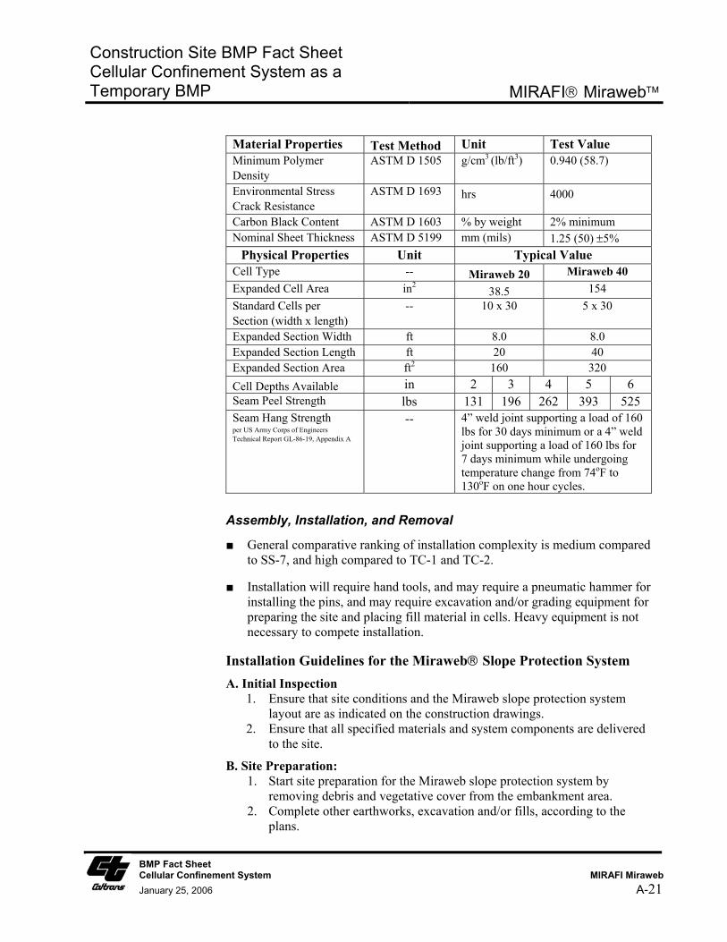
Materials
Miraweb 20 and Miraweb 40 cellular confinement systems are produced from high density polyethylene (HDPE) strips ultrasonically bonded to form an expandable cell type pattern.
BMP Fact Sheet Cellular Confinement System MIRAFI Miraweb
January 25, 2006 A-20
Construction Site BMP Fact Sheet Cellular Confinement System as a Temporary BMP
MIRAFI Miraweb
Material Properties Test Method Unit Test Value Minimum Polymer Density
ASTM D 1505 g/cm3 (lb/ft3) 0.940 (58.7)
Environmental Stress Crack Resistance
ASTM D 1693 hrs 4000
Carbon Black Content ASTM D 1603 % by weight 2% minimum Nominal Sheet Thickness ASTM D 5199 mm (mils) 1.25 (50) ±5%
Physical Properties Unit Typical Value Cell Type -- Miraweb 20 Miraweb 40 Expanded Cell Area in2 38.5 154 Standard Cells per Section (width x length)
-- 10 x 30 5 x 30
Expanded Section Width ft 8.0 8.0 Expanded Section Length ft 20 40 Expanded Section Area ft2 160 320 Cell Depths Available in 2 3 4 5 6 Seam Peel Strength lbs 131 196 262 393 525 Seam Hang Strength per US Army Corps of Engineers Technical Report GL-86-19, Appendix A
-- 4” weld joint supporting a load of 160 lbs for 30 days minimum or a 4” weld joint supporting a load of 160 lbs for 7 days minimum while undergoing temperature change from 74oF to 130oF on one hour cycles.
Assembly, Installation, and Removal
■ General comparative ranking of installation complexity is medium compared to SS-7, and high compared to TC-1 and TC-2.
■ Installation will require hand tools, and may require a pneumatic hammer for installing the pins, and may require excavation and/or grading equipment for preparing the site and placing fill material in cells. Heavy equipment is not necessary to compete installation.
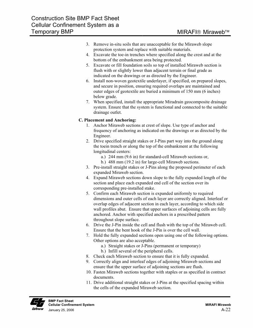
Installation Guidelines for the Miraweb Slope Protection System A. Initial Inspection
1. Ensure that site conditions and the Miraweb slope protection system layout are as indicated on the construction drawings.
2. Ensure that all specified materials and system components are delivered to the site.
B. Site Preparation: 1. Start site preparation for the Miraweb slope protection system by
removing debris and vegetative cover from the embankment area. 2. Complete other earthworks, excavation and/or fills, according to the
plans.
BMP Fact Sheet Cellular Confinement System MIRAFI Miraweb
January 25, 2006 A-21
Construction Site BMP Fact Sheet Cellular Confinement System as a Temporary BMP
MIRAFI Miraweb
3. Remove in-situ soils that are unacceptable for the Miraweb slope protection system and replace with suitable materials.
4. Excavate the toe-in trenches where specified along the crest and at the bottom of the embankment area being protected.
5. Excavate or fill foundation soils so top of installed Miraweb section is flush with or slightly lower than adjacent terrain or final grade as indicated on the drawings or as directed by the Engineer.
6. Install non-woven geotextile underlayer, if specified, on prepared slopes, and secure in position, ensuring required overlaps are maintained and outer edges of geotextile are buried a minimum of 150 mm (6 inches) below grade.
7. When specified, install the appropriate Miradrain geocomposite drainage system. Ensure that the system is functional and connected to the suitable drainage outlet.
C. Placement and Anchoring: 1. Anchor Miraweb sections at crest of slope. Use type of anchor and
frequency of anchoring as indicated on the drawings or as directed by the Engineer.
2. Drive specified straight stakes or J-Pins part way into the ground along the toein trench or along the top of the embankment at the following longitudinal centers:
a.) 244 mm (9.6 in) for standard-cell Miraweb sections or, b.) 488 mm (19.2 in) for large-cell Miraweb sections.
3. Pre-install straight stakes or J-Pins along the proposed perimeter of each expanded Miraweb section.
4. Expand Miraweb sections down slope to the fully expanded length of the section and place each expanded end cell of the section over its corresponding pre-installed stake.
5. Confirm each Miraweb section is expanded uniformly to required dimensions and outer cells of each layer are correctly aligned. Interleaf or overlap edges of adjacent section in each layer, according to which side wall profiles abut. Ensure that upper surfaces of adjoining cells are fully anchored. Anchor with specified anchors in a prescribed pattern throughout slope surface.
6. Drive the J-Pin inside the cell and flush with the top of the Miraweb cell. Ensure that the bent hook of the J-Pin is over the cell wall.
7. Hold the fully expanded sections open using one of the following options. Other options are also acceptable.
a.) Straight stakes or J-Pins (permanent or temporary) b.) Infill several of the peripheral cells.
8. Check each Miraweb section to ensure that it is fully expanded. 9. Correctly align and interleaf edges of adjoining Miraweb sections and
ensure that the upper surface of adjoining sections are flush. 10. Fasten Miraweb sections together with staples or as specified in contract
documents. 11. Drive additional straight stakes or J-Pins at the specified spacing within
the cells of the expanded Miraweb section.
BMP Fact Sheet Cellular Confinement System MIRAFI Miraweb
January 25, 2006 A-22
Construction Site BMP Fact Sheet Cellular Confinement System as a Temporary BMP
MIRAFI Miraweb
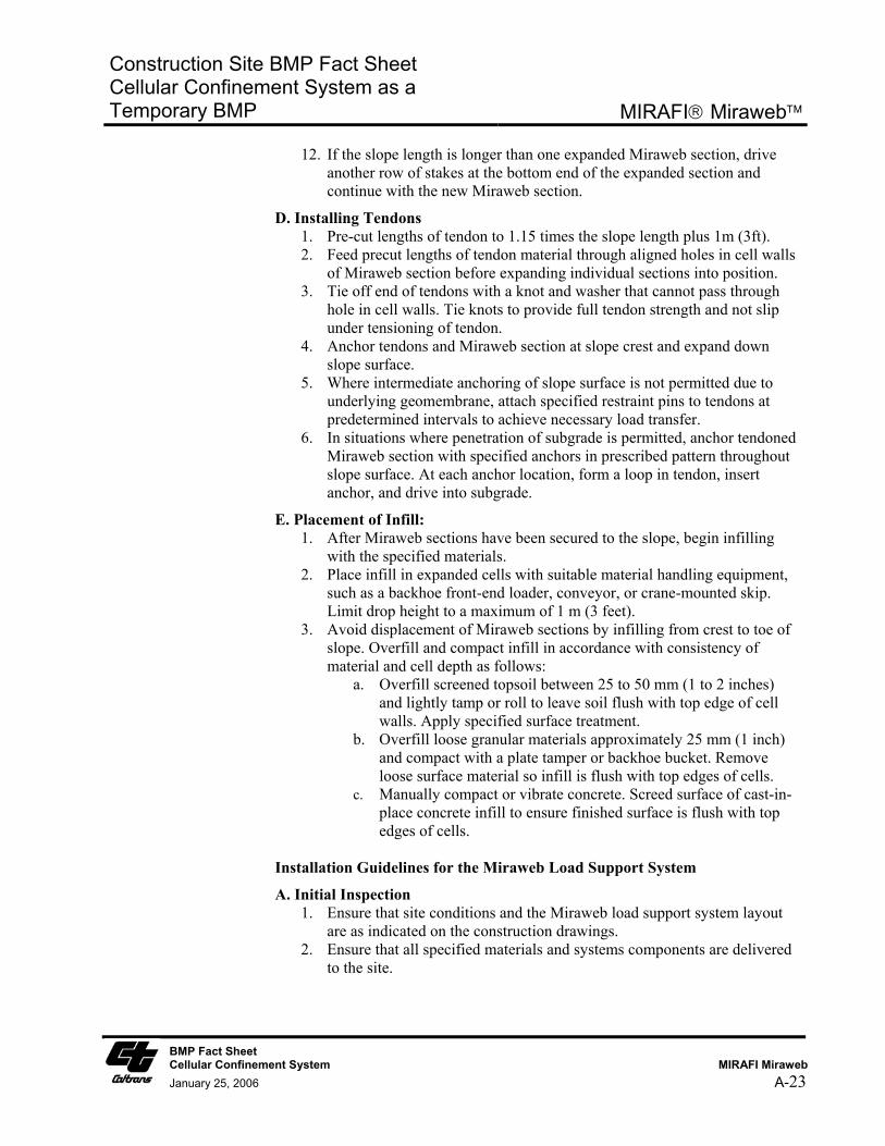
12. If the slope length is longer than one expanded Miraweb section, drive another row of stakes at the bottom end of the expanded section and continue with the new Miraweb section.
D. Installing Tendons 1. Pre-cut lengths of tendon to 1.15 times the slope length plus 1m (3ft). 2. Feed precut lengths of tendon material through aligned holes in cell walls
of Miraweb section before expanding individual sections into position. 3. Tie off end of tendons with a knot and washer that cannot pass through
hole in cell walls. Tie knots to provide full tendon strength and not slip under tensioning of tendon.
4. Anchor tendons and Miraweb section at slope crest and expand down slope surface.
5. Where intermediate anchoring of slope surface is not permitted due to underlying geomembrane, attach specified restraint pins to tendons at predetermined intervals to achieve necessary load transfer.
6. In situations where penetration of subgrade is permitted, anchor tendoned Miraweb section with specified anchors in prescribed pattern throughout slope surface. At each anchor location, form a loop in tendon, insert anchor, and drive into subgrade.
E. Placement of Infill: 1. After Miraweb sections have been secured to the slope, begin infilling
with the specified materials. 2. Place infill in expanded cells with suitable material handling equipment,
such as a backhoe front-end loader, conveyor, or crane-mounted skip. Limit drop height to a maximum of 1 m (3 feet).
3. Avoid displacement of Miraweb sections by infilling from crest to toe of slope. Overfill and compact infill in accordance with consistency of material and cell depth as follows:
a. Overfill screened topsoil between 25 to 50 mm (1 to 2 inches) and lightly tamp or roll to leave soil flush with top edge of cell walls. Apply specified surface treatment.
b. Overfill loose granular materials approximately 25 mm (1 inch) and compact with a plate tamper or backhoe bucket. Remove loose surface material so infill is flush with top edges of cells.
c. Manually compact or vibrate concrete. Screed surface of cast-in-place concrete infill to ensure finished surface is flush with top edges of cells.
Installation Guidelines for the Miraweb Load Support System
A. Initial Inspection 1. Ensure that site conditions and the Miraweb load support system layout
are as indicated on the construction drawings. 2. Ensure that all specified materials and systems components are delivered
to the site.
BMP Fact Sheet Cellular Confinement System MIRAFI Miraweb
January 25, 2006 A-23
Construction Site BMP Fact Sheet Cellular Confinement System as a Temporary BMP
MIRAFI Miraweb
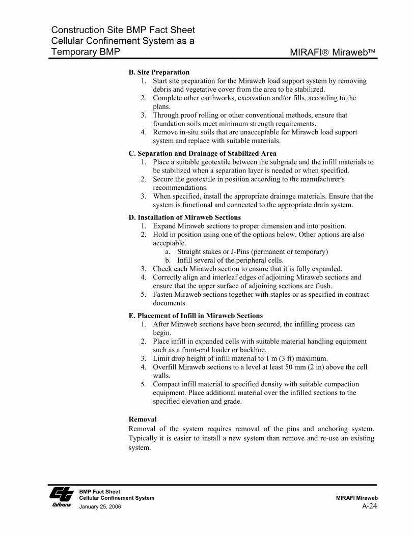
B. Site Preparation 1. Start site preparation for the Miraweb load support system by removing
debris and vegetative cover from the area to be stabilized. 2. Complete other earthworks, excavation and/or fills, according to the
plans. 3. Through proof rolling or other conventional methods, ensure that
foundation soils meet minimum strength requirements. 4. Remove in-situ soils that are unacceptable for Miraweb load support
system and replace with suitable materials.
C. Separation and Drainage of Stabilized Area 1. Place a suitable geotextile between the subgrade and the infill materials to
be stabilized when a separation layer is needed or when specified. 2. Secure the geotextile in position according to the manufacturer's
recommendations. 3. When specified, install the appropriate drainage materials. Ensure that the
system is functional and connected to the appropriate drain system.
D. Installation of Miraweb Sections 1. Expand Miraweb sections to proper dimension and into position. 2. Hold in position using one of the options below. Other options are also
acceptable. a. Straight stakes or J-Pins (permanent or temporary) b. Infill several of the peripheral cells.
3. Check each Miraweb section to ensure that it is fully expanded. 4. Correctly align and interleaf edges of adjoining Miraweb sections and
ensure that the upper surface of adjoining sections are flush. 5. Fasten Miraweb sections together with staples or as specified in contract
documents.
E. Placement of Infill in Miraweb Sections 1. After Miraweb sections have been secured, the infilling process can
begin. 2. Place infill in expanded cells with suitable material handling equipment
such as a front-end loader or backhoe. 3. Limit drop height of infill material to 1 m (3 ft) maximum. 4. Overfill Miraweb sections to a level at least 50 mm (2 in) above the cell
walls. 5. Compact infill material to specified density with suitable compaction
equipment. Place additional material over the infilled sections to the specified elevation and grade.
Removal Removal of the system requires removal of the pins and anchoring system. Typically it is easier to install a new system than remove and re-use an existing system.
BMP Fact Sheet Cellular Confinement System MIRAFI Miraweb
January 25, 2006 A-24
Construction Site BMP Fact Sheet Cellular Confinement System as a Temporary BMP
MIRAFI Miraweb
Maintenance and Inspection
■ Maintenance and inspection level of effort is Medium.
■ Inspect weekly in winter for slope instability. Typically, redirect water from rills, fill rills with soil, compact soil in cells, and secure with erosion control blanket or top with mulch if necessary. Inspect anchoring system at top and toe, pins, erosion of material from the cells.
Literature Sources ■ MIRAFI website, www.mirafi.com and manufacturer product data sheets.
■ Caltrans, 2003. Caltrans Erosion Control New Technology Report, CTSW-RT-03-049.
■ Caltrans, 2002. Project Planning and Design Guide.
BMP Fact Sheet Cellular Confinement System MIRAFI Miraweb
January 25, 2006 A-25
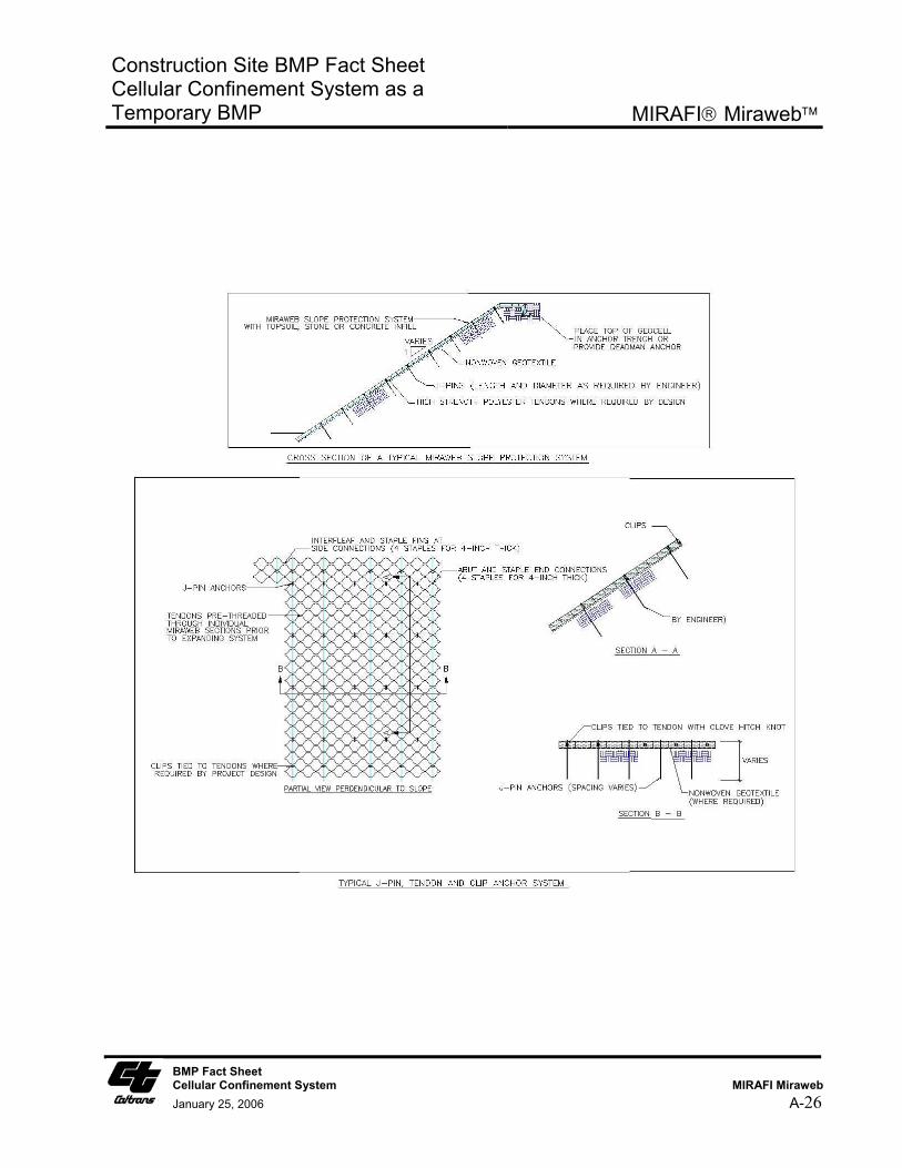
Construction Site BMP Fact Sheet Cellular Confinement System as a Temporary BMP
MIRAFI Miraweb
BMP Fact Sheet Cellular Confinement System MIRAFI Miraweb
January 25, 2006 A-26
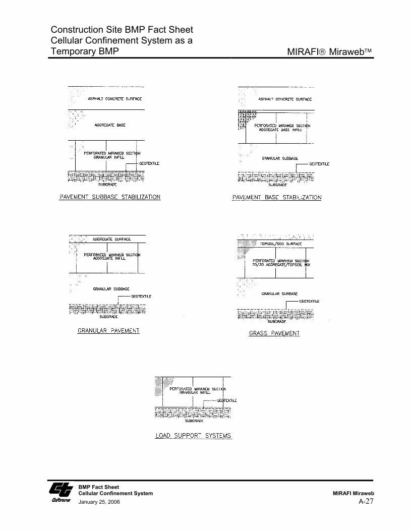
Construction Site BMP Fact Sheet Cellular Confinement System as a Temporary BMP
MIRAFI Miraweb
BMP Fact Sheet Cellular Confinement System MIRAFI Miraweb
January 25, 2006 A-27
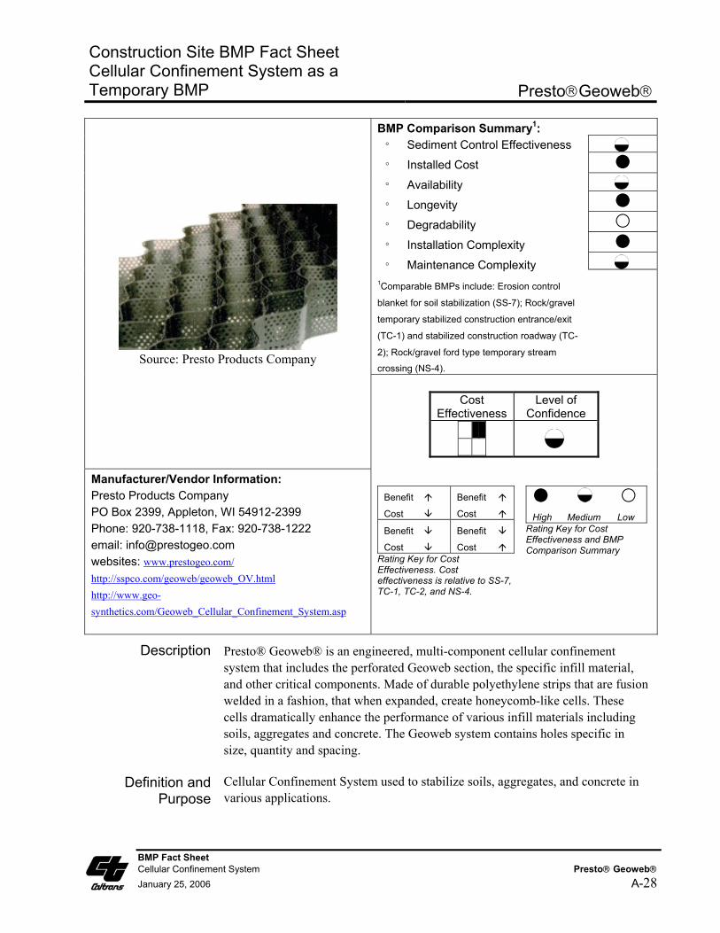
Construction Site BMP Fact Sheet Cellular Confinement System as a Temporary BMP
PrestoGeoweb
BMP Comparison Summary1: ° Sediment Control Effectiveness
° Installed Cost
° Availability
° Longevity
° Degradability
° Installation Complexity
° Maintenance Complexity 1Comparable BMPs include: Erosion control
blanket for soil stabilization (SS-7); Rock/gravel
temporary stabilized construction entrance/exit
(TC-1) and stabilized construction roadway (TC-
2); Rock/gravel ford type temporary stream
crossing (NS-4).
Source: Presto Products Company
Cost Effectiveness
Level of Confidence
Manufacturer/Vendor Information: Presto Products Company PO Box 2399, Appleton, WI 54912-2399 Phone: 920-738-1118, Fax: 920-738-1222 email: [email protected] websites: www.prestogeo.com/ http://sspco.com/geoweb/geoweb_OV.html http://www.geo-synthetics.com/Geoweb_Cellular_Confinement_System.asp
Benefit
Cost
Benefit
Cost Benefit
Cost Benefit
Cost Rating Key for Cost Effectiveness. Cost effectiveness is relative to SS-7, TC-1, TC-2, and NS-4.
High Medium Low
Rating Key for Cost Effectiveness and BMP Comparison Summary
Description Presto® Geoweb® is an engineered, multi-component cellular confinement system that includes the perforated Geoweb section, the specific infill material, and other critical components. Made of durable polyethylene strips that are fusion welded in a fashion, that when expanded, create honeycomb-like cells. These cells dramatically enhance the performance of various infill materials including soils, aggregates and concrete. The Geoweb system contains holes specific in size, quantity and spacing.
Definition and Purpose
Cellular Confinement System used to stabilize soils, aggregates, and concrete in various applications.
BMP Fact Sheet Cellular Confinement System Presto Geoweb January 25, 2006 A-28
Construction Site BMP Fact Sheet Cellular Confinement System as a Temporary BMP
PrestoGeoweb
Appropriate Applications
■ Temporary Stream Crossing: Temporary ford type stream crossing in dry washes or ephemeral streams in arid areas during non-rainy season as described in NS-4. CCS are appropriate for streams that would benefit from an influx of gravel.
■ Ground stabilization, load support and tracking control at temporary stabilized construction entrance/exit, temporary construction access roads, and parking/storage areas.
■ Temporary slope stabilization, protection and revegetation on slopes (generally between 1V to 3H and 1V to 1H).
Advantages ■ Once expanded to its maximum extension and filled in with soil or gravel the CCS becomes inextensible and monolithic, providing an effective means of confinement for unconsolidated materials lying within single cells and preventing their movement even on steep slopes, or also from substantial dragging forces such as those exerted by sheet runoff.
■ Reduces runoff and sediment transport by confining soils within geocells. All cells are hydraulically interconnected and the CCS attains good permeability, facilitates the absorption of water during precipitation, diminishes surface runoff and consequently erosion.
■ Fords are the least expensive of the temporary stream crossing options outlined in NS-4. Relatively little rock or gravel is needed because the CCS provides the stability. For temporary fords, the CCS can be filled with natural river gravel, which may be a benefit to the stream upon removal of the CCS.
■ Improves soil structure and increases load support. Gravel/rock thickness may be reduced on temporary access road because CCS provides additional support. Use of a geocell can significantly reduce the amount and/or quality of aggregate required to stabilize a poor load bearing soil. If the temporary construction access road alignment is identical to a permanent roadway, use of the CCS may benefit the roadway section design. Note that use of CCS for both temporary and permanent applications at the same installation requires that it be designed accordingly and shown as such on both the Water Pollution Control Drawings and the Project Construction Drawings.
■ Possible alternative to removal/replacement of soft, poor soils along temporary access road routes and storage/parking areas.
■ Reduces formation of rills, gullies, and channels.
■ Sections collapse into lightweight, compact bundles for ease in shipping.
■ For slope stabilization, CCS can be vegetated and thus serve both as a temporary and permanent BMP. Can minimize compaction and fill import. Note that use of CCS for both temporary and permanent soil stabilization BMP applications at the same installation requires that it be designed
BMP Fact Sheet Cellular Confinement System Presto Geoweb January 25, 2006 A-29
Construction Site BMP Fact Sheet Cellular Confinement System as a Temporary BMP
PrestoGeoweb
accordingly and shown as such on both the Water Pollution Control Drawings and the Project Construction Drawings. If it is not called out on the plans as a permanent soil stabilization BMP, construction site inspectors may call for its removal at completion of construction.
■ The perforated design of the CCS increases performance in slope and channel protection, earth retention, and load support applications over non-perforated confinement and stabilization systems by:
- Improved lateral drainage through cell walls resulting in better performance in saturated soils
- Greater cell wall/infill lock-up with coarse materials such as aggregate and concrete
- Increased root lock-up in vegetated systems
- Healthier soil environment due to the cell openings allowing passage of water, nutrients and soil organisms
- Reduced installation and long-term maintenance costs resulting from reduced material weight and greater infill lock-up.
■ As a road base reinforcement system, CCS spreads loads across the cellular confinement system and the webwork behaves like a stiff but flexible horizontal laminar element beneath the load bearing surface. The CCS base reinforcement provides the ideal layer requirement to support and isolate the traffic bearing surface from soft subgrade conditions below.
Limitations ■ For slope stabilization applications CCS are more expensive than other erosion control measures due to labor and material costs. Typically this system is used as a permanent slope soil stabilization BMP in areas where other BMPs are not appropriate.
■ Not suitable for temporary use as channel slope protection in channelized flow conditions with moderate to high velocities (greater than 4-6 ft/s), particularly when using soil infill. Permanent applications of CCS in channelized flow conditions may be acceptable when appropriately designed.
■ Not suitable for temporary ford type stream crossings during rainy season or in perennial streams. CCS must be removed from stream upon completion of construction.
■ Not to be used on solid rock slopes. Maximum slope 1V to 1H.
■ Fill material within cells may be washed out in steep slope application if temporary cover with an SS-7 Rolled Erosion Control Product is not provided.
BMP Fact Sheet Cellular Confinement System Presto Geoweb January 25, 2006 A-30
Construction Site BMP Fact Sheet Cellular Confinement System as a Temporary BMP
PrestoGeoweb
BMP Fact Sheet Cellular Confinement System Presto Geoweb January 25, 2006 A-31
■ Erosion control effectiveness is highly dependent upon proper installation. Requires proper pins and anchors to secure in place. If there is a long slope upstream, a diversion ditch is recommend upslope of the CCS.
■ Typically it is not cost effective to reuse CCS since the majority of the installation cost consists of equipment and labor.
Effectiveness ■ Relative effectiveness compared to SS-7 (Rolled Erosion Control Products) used in a temporary slope stabilization application is Low to Moderate, since an interim SS-7 product is typically required to cover the CCS soil until vegetation is established.
■ Relative effectiveness compared to temporary stabilized construction entrance/exit (TC-1) and stabilized construction roadway (TC-2) is Moderate to High, since the CCS provides enhanced ground stabilization and load support while using less volume of aggregate fill material.
■ Relative effectiveness compared to a gravel/rock ford type temporary stream crossing per NS-4 is Moderate to High since the CCS provides enhanced stability with less gravel/rock material.
Cost and Availability
■ Relative installed cost compared to SS-7 (Rolled Erosion Control Products) is Moderate to High. Relative cost is high compared to biodegradable rolled erosion control products and Moderate to High compared to non-biodegradable erosion control products.
■ Relative installed cost compared to TC-1 is Medium and to TC-2 is Moderate to High. However, cost savings may be realized, and relative costs low, if use of CCS eliminates the need for removal and replacement of poor soils.
■ Relative installed cost compared to rock/gravel ford type temporary stream crossing per NS-4 is Moderate.
■ Production Rate/Installation Cost is High: Up to $1-1.80/ft2 ($45,000-$78,000 per acre) for a typical slope protection or load support application using 3- to 4-inch deep cells. Installed costs of CCS is highly dependent on site conditions, project size, and local costs of infill materials, equipment, and labor.
■ Product availability, or delivery time, is Moderate (two to four weeks).
Standards and Specifications
Key Design Elements
■ Determine if use is temporary only or both temporary and permanent.
■ Determine temporary application type and compare to other systems and materials based on site conditions to determine most cost effective system that provides the required amount of erosion protection.
■ Stability analysis for slope applications.
Construction Site BMP Fact Sheet Cellular Confinement System as a Temporary BMP
PrestoGeoweb
BMP Fact Sheet Cellular Confinement System Presto Geoweb January 25, 2006 A-32
■ Required thickness or depth of CCS.
■ Required site preparation and requirement for geotextile underlay/overlay.
■ Hydraulic flow condition (sheet flow or channelized flow and expected flow velocities). Determine if upstream areas will contribute concentrated flow to CCS.
■ Infill material (soil or other aggregate)
■ Anchor pin spacing and anchoring system.
Materials
■ Product Description: Fabricated polymer article (chemical family: Polyolefin)
■ Available in 3 cell sizes, GW20V, GW30V, GW40V, and 4 depths, 3 in, 4 in, 6 in, 8 in. Sold in panels, Geoweb can be variably expanded to the sizes shown in the table below.
Test Method Value
Polymer Density ASTM D 1505 0.935 – 0.965 g/cc
Sheet Gauge ASTM D 5199 50 mil -5% +10%
Carbon Black Content ASTM D 1603 1.5-2.0%
Environmental Stress Crack Resistance
ASTM D 1693 3,000 hours
Physical Properties Unit Typical Value Cell Type -- GW20V GW30V GW40V Expanded Cell Area in2 44.8 71.3 187 Nominal Expanded Cell Size (width x length)
-- 10.2 x 8.8 12.6 x 11.3 20 x 18.7
Expanded Section Width ft 7.7 to 9.2 7.7 to 9.2 7.7 to 9.2 Expanded Section Length ft 12 to 27.3 15.4 to 35.1 25.4 to 58.2 Expanded Section Area ft2 Variable Variable Variable Cell Depths Available in 3 4 6 8 Seam Peel Strength lbs 240 320 480 640 Long-term Seam Peel Strength
-- Long-term seam peel strength test shall be performed on all resin or pre-manufactured sheet or strips. A 4 inch wide seam sample shall support a 160lb load for a period of 7 days minimum in a temperature controlled environment under going a temperature change on a 1-hour cycle from ambient room to 130oF. Ambient room temperature is per ASTM E 41.
Construction Site BMP Fact Sheet Cellular Confinement System as a Temporary BMP
PrestoGeoweb
Assembly, Installation, and Removal
■ General comparative ranking of installation complexity is medium compared to SS-7, and high compared to TC-1 and TC-2.
■ Installation will require hand tools, and may require a pneumatic hammer for installing the pins, and may require excavation and/or grading equipment for preparing the site and placing fill material in cells. Heavy equipment is not necessary to compete installation.
■ Geoweb sections shall be provided with a series of aligned holes through the cell walls for the insertion of tendons. Tendons are inserted in the field such that they pass through the Geoweb section in the direction of expansion. The ATRA Clip shall be used as a load transfer pin within the tendoned Geoweb system. Geoweb sections, with or without tendons, shall be anchored in accordance with construction drawings. Rows of ATRA Anchors or stake anchors shall engage and bear against the cell walls, or engage and hold the integral tendons against the foundation soil.
■ Types of equipment: Anchors (ATRA GFRP anchor or stake anchor), restraint pins (ATRA Clip), tendons (3-strand twisted rope), welding equipment, laborers
General Installation Procedures
1. Prepare the site by removing all vegetative cover, debris and any unacceptable soils from the area where the Geoweb wall is to be placed. Replace any removed soils with acceptable materials and complete all earthwork in accordance with job specifications.
2. If geotextile is required by the job specifications, installation should be accomplished in accordance with the manufacturer’s recommendations.
3. Partially install stakes or J-hooks, leaving a protruding length of the cell depth plus approximately 2 in [50 mm], along the top edge of the area in which the Geoweb is to be installed. A string or chalk line may be used to align staking locations and borders.
4. Geoweb sections should be stretched past the designed length (typically, 20 ft [6.1m]), the allow to settle back to the designed length. Set the end cells of the geocell sections over the previously installed stakes and complete installation of the stakes or J-hooks flush with or slightly below cell walls.
5. Adjoining sections must be level and flush with each other. Overlap the sides of the Geoweb sections and butt the ends together. Secure adjoining sections to each other using a pneumatic stapler, hot rings or other means as required by the job specifications.
BMP Fact Sheet Cellular Confinement System Presto Geoweb January 25, 2006 A-33
Construction Site BMP Fact Sheet Cellular Confinement System as a Temporary BMP
PrestoGeoweb
6. Install the balance of the stakes or J-hooks as required by the job specifications.
7. When the Geoweb has been properly laid into place, the system should be infilled using the materials specified in the job specifications.
8. To prevent possible damage to the system, limit the drop height of the infill to no more than 3 ft [1 m].
9. When using sand, granular or top soil fills, overfill the Geoweb sections by 1 - 2 in [25 - 50 mm] to allow for settling and compaction.
10. Sand and granular fills should then be blade compacted to the top of the cells. Top soil fills should be compacted with the loader or back hoe or with a tamper plate. Concrete fills should be manually raked and machine finished.
Anchoring
The number and type of anchors is determined by subgrade density, weight and type of infill, slope grade and environmental conditions. Anchors should be left in place after installation. Systems with a low to moderate loading should be anchored using ”J” hooks or wooden stakes. Sites with severe conditions require further reinforcement. Anchoring the Geoweb with three or five tendons per section on slope grades up to 1:1 has been utilized with good success. The anchoring system utilizing tendons and “J” hooks should be set deep enough to reach a solid subbase. If the slope subbase is soft or porous, the anchoring system must be set very deep in order to hold the installation in place. The holes for tendons, which are drilled lengthwise in the collapsed form, may be drilled in the field before installation or during the manufacturing process. The tendon material should have a tensile strength sufficient to support the total theoretical load, and should be constructed of cable or creep resistant woven polyester. Before selecting the anchoring method, it is necessary to calculate sliding forces, or the force which has to be overcome to keep the Geoweb from sliding or moving. If the NSF is negative, then the friction between the Geoweb and slope is sufficient to hold the system in place.
Staking the Geoweb to a slope is the most common anchoring method used if there is no geomembrane present and if the soil has adequate strength to retain the stakes. Steel reinforcing bars bent into a “candy cane shape called J-hooks are the preferred type of stake. General Rule: the length of the stake should be three times the cell height.
If conditions require that adjacent sections of the Geoweb be joined together rather than butted against each other, hog rings or staples can be used. Staples are
BMP Fact Sheet Cellular Confinement System Presto Geoweb January 25, 2006 A-34
Construction Site BMP Fact Sheet Cellular Confinement System as a Temporary BMP
PrestoGeoweb
normally attached using a pneumatic staple gun with industrial grade staples. The staples or rings are attached through each set of adjoining cells
Tendons are used on steep slopes when additional support is needed, or where the use of stakes is prohibited (such as a rock base or a geomembrane liner). They are also used when more than one section of a Geoweb is needed to cover a slope from top to bottom. The three important characteristics of tendons are strength, resistance to elongation and durability. The design load and spacing of the tendons is determined by the force to be supported. A large number of lighter tendons is preferable to a smaller number of heavier tendons. Batten strips or large washers at the bottom of the lowest section of the Geoweb are necessary to avoid stress concentrations. Sometimes it is necessary to pre-stretch and open the geocell prior to placing it on a slope. This is especially true if part or all of a section is going under water. In most cases an installation frame can be built from common lumber (or PVC) and rebar
Removal Removal of the system requires removal of the pins and anchoring system. Typically it is easier to install a new system than remove and re-use an existing system.
Maintenance and Inspection
■ Maintenance and inspection level of effort is Medium
■ Inspect weekly in winter for slope instability. Typically, redirect water from rills, fill rills with soil, compact soil in cells, and secure with erosion control blanket or top with mulch if necessary. Inspect anchoring system at top and toe, pins, erosion of material from the cells.
Literature Sources ■ Geoweb Material Safety Data Sheet located at: http://www.geo-synthetics.com/pdf/products/Presto/msdasheetgw1.pdf
■ Geoweb Material Specifications located at: http://www.geo-synthetics.com/pdf/products/Presto/v_series_geoweb_material_specification.pdf
■ 2005. Soil Stabilization Products Company. 18 Years of Solving Problems with Caltrans. http://sspco.com/pdf/3179.pdf
■ Caltrans, 2003. Caltrans Erosion Control New Technology Report, CTSW-RT-03-049.
■ Caltrans, 2002. Project Planning and Design Guide.
BMP Fact Sheet Cellular Confinement System Presto Geoweb January 25, 2006 A-35
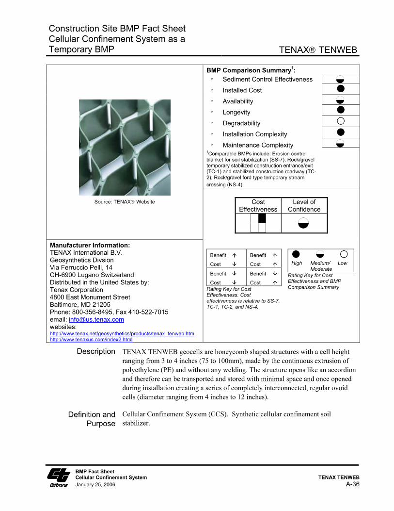
Construction Site BMP Fact Sheet Cellular Confinement System as a Temporary BMP
TENAX TENWEB
BMP Comparison Summary1: ° Sediment Control Effectiveness
° Installed Cost
° Availability
° Longevity
° Degradability
° Installation Complexity
° Maintenance Complexity 1Comparable BMPs include: Erosion control blanket for soil stabilization (SS-7); Rock/gravel temporary stabilized construction entrance/exit (TC-1) and stabilized construction roadway (TC-2); Rock/gravel ford type temporary stream crossing (NS-4).
Source: TENAX Website
Cost
Effectiveness Level of
Confidence
Manufacturer Information: TENAX International B.V. Geosynthetics Divsion Via Ferruccio Pelli, 14 CH-6900 Lugano Switzerland Distributed in the United States by: Tenax Corporation 4800 East Monument Street Baltimore, MD 21205 Phone: 800-356-8495, Fax 410-522-7015 email: [email protected] websites: http://www.tenax.net/geosynthetics/products/tenax_tenweb.htm http://www.tenaxus.com/index2.html
Benefit
Cost
Benefit
Cost Benefit
Cost Benefit
Cost Rating Key for Cost Effectiveness. Cost effectiveness is relative to SS-7, TC-1, TC-2, and NS-4.
High Medium/ Low Moderate
Rating Key for Cost Effectiveness and BMP Comparison Summary
Description TENAX TENWEB geocells are honeycomb shaped structures with a cell height ranging from 3 to 4 inches (75 to 100mm), made by the continuous extrusion of polyethylene (PE) and without any welding. The structure opens like an accordion and therefore can be transported and stored with minimal space and once opened during installation creating a series of completely interconnected, regular ovoid cells (diameter ranging from 4 inches to 12 inches).
Definition and Purpose
Cellular Confinement System (CCS). Synthetic cellular confinement soil stabilizer.
BMP Fact Sheet Cellular Confinement System TENAX TENWEB January 25, 2006 A-36
Construction Site BMP Fact Sheet Cellular Confinement System as a Temporary BMP
TENAX TENWEB
Appropriate Applications
■ Temporary Stream Crossing: Temporary ford type stream crossing in dry washes or ephemeral streams in arid areas during non-rainy season as described in NS-4. CCS are appropriate for streams that would benefit from an influx of gravel.
■ Ground stabilization, load support and tracking control at temporary stabilized construction entrance/exit, temporary construction access roads, and parking/storage areas.
■ Temporary slope stabilization, protection and revegetation on slopes (generally between 1V to 3H and 1V to 1H).
Advantages ■ Once expanded to its maximum extension and filled in with soil or gravel the CCS becomes inextensible and monolithic, providing an effective means of confinement for unconsolidated materials lying within single cells and preventing their movement even on steep slopes, or also from substantial dragging forces such as those exerted by sheet runoff.
■ Reduces runoff and sediment transport by confining soils within geocells. All cells are hydraulically interconnected and the CCS attains good permeability, facilitates the absorption of water during precipitation, diminishes surface runoff and consequently erosion.
■ Fords are the least expensive of the temporary stream crossing options outlined in NS-4. Relatively little rock or gravel is needed because the CCS provides the stability. For temporary fords, the CCS can be filled with natural river gravel, which may be a benefit to the stream upon removal of the CCS.
■ Improves soil structure and increases load support. Gravel/rock thickness may be reduced on temporary access road because CCS provides additional support. Use of a geocell can significantly reduce the amount and/or quality of aggregate required to stabilize a poor load bearing soil. If the temporary construction access road alignment is identical to a permanent roadway, use of the CCS may benefit the roadway section design. Note that use of CCS for both temporary and permanent applications at the same installation requires that it be designed accordingly and shown as such on both the Water Pollution Control Drawings and the Project Construction Drawings.
■ Possible alternative to removal/replacement of soft, poor soils along temporary access road routes and storage/parking areas.
■ Reduces formation of rills, gullies, and channels.
■ Lightweight and easy to transport.
■ For slope stabilization, CCS can be vegetated and thus serve both as a temporary and permanent BMP. Can minimize compaction and fill import. Note that use of CCS for both temporary and permanent soil stabilization BMP applications at the same installation requires that it be designed
BMP Fact Sheet Cellular Confinement System TENAX TENWEB January 25, 2006 A-37
Construction Site BMP Fact Sheet Cellular Confinement System as a Temporary BMP
TENAX TENWEB
accordingly and shown as such on both the Water Pollution Control Drawings and the Project Construction Drawings. If it is not called out on the plans as a permanent soil stabilization BMP, construction site inspectors may call for its removal at completion of construction.
Limitations ■ For slope stabilization applications CCS are more expensive than other erosion control measures due to labor and material costs. Typically this system is used as a permanent slope soil stabilization BMP in areas where other BMPs are not appropriate.
■ Not suitable for temporary use as channel slope protection in channelized flow conditions with moderate to high velocities (greater than 4-6 ft/s), particularly when using soil infill. Permanent applications of CCS in channelized flow conditions may be acceptable when appropriately designed.
■ Not suitable for temporary ford type stream crossings during rainy season or in perennial streams. CCS must be removed from stream upon completion of construction.
■ Not to be used on solid rock slopes. Maximum slope 1V to 1H.
■ Fill material within cells may be washed out in steep slope application if temporary cover with an SS-7 Rolled Erosion Control Product is not provided.
■ Erosion control effectiveness is highly dependent upon proper installation. Requires proper pins and anchors to secure in place. If there is a long slope upstream, a diversion ditch is recommend upslope of the CCS.
■ Typically it is not cost effective to reuse CCS since the majority of the installation cost consists of equipment and labor.
Effectiveness ■ Relative effectiveness compared to SS-7 (Rolled Erosion Control Products) used in a temporary slope stabilization application is Low to Moderate, since an interim SS-7 product is typically required to cover the CCS soil until vegetation is established.
■ Relative effectiveness compared to temporary stabilized construction entrance/exit (TC-1) and stabilized construction roadway (TC-2) is Moderate to High, since the CCS provides enhanced ground stabilization and load support while using less volume of aggregate fill material.
■ Relative effectiveness compared to a gravel/rock ford type temporary stream crossing per NS-4 is Moderate to High since the CCS provides enhanced stability with less gravel/rock material.
BMP Fact Sheet Cellular Confinement System TENAX TENWEB January 25, 2006 A-38
Construction Site BMP Fact Sheet Cellular Confinement System as a Temporary BMP
TENAX TENWEB
Cost and Availability
■ Relative installed cost compared to SS-7 (Rolled Erosion Control Products) is Moderate to High. Relative cost is high compared to biodegradible rolled erosion control products and Moderate to High compared to non-biodegradible erosion control products.
■ Relative installed cost compared to TC-1 is Medium and to TC-2 is Moderate to High. However, cost savings may be realized, and relative costs low, if use of CCS eliminates the need for removal and replacement of poor soils.
■ Relative installed cost compared to rock/gravel ford type temporary stream crossing per NS-4 is Moderate.
■ Production Rate/Installation Cost is High: $1.00 - $1.80/ft2 ($45,000 - $78,000 per acre) for a typical slope protection or load support application using 3- to 4-inch deep cells. Installed costs of CCS is highly dependent on site conditions, project size, and local costs of infill materials, equipment, and labor.
■ Product availability, or delivery time, is Moderate (typically one week).
Standards and Specifications
Key Design Elements
■ Determine if use is temporary only or both temporary and permanent.
■ Determine temporary application type and compare to other systems and materials based on site conditions to determine most cost effective system that provides the required amount of erosion protection.
■ Stability analysis for slope applications.
■ Required thickness or depth of CCS.
■ Required site preparation and requirement for geotextile underlay/overlay.
■ Hydraulic flow condition (sheet flow or channelized flow and expected flow velocities). Determine if upstream areas will contribute concentrated flow to CCS.
■ Infill material (soil or gravel).
■ Anchor pin spacing and anchoring system.
Materials
The erosion control geocells shall be a monolithic honeycomb structure, extruded from high density polyethylene, green in colour. The junctions between the longitudinal strips shall be an integral part of the geocell structure and shall under no circumstances be obtained by weaving, knitting or bonding single strips. The junctions shall be vertically opened to allow hydraulic flow between the adjacent cells.
The erosion control geocell panels shall be identified in accordance with ISO 10320 Standard and manufactured in accordance with ISO 9001 Quality Assurance System. The geocell shall be certified “CE MARKING” in accordance
BMP Fact Sheet Cellular Confinement System TENAX TENWEB January 25, 2006 A-39
Construction Site BMP Fact Sheet Cellular Confinement System as a Temporary BMP
TENAX TENWEB
with the requirements of EN 13253 (Characteristics required for use in erosion control works).
The erosion control geocells shall comply in full with the following specification:
TECHNICAL CHARACTERISTICS
TEST METHOD UNIT TYPE
G1 TYPE G2
TYPE G3
TYPE G4 NOTES
Cell Inner Dimensions mm 75 x 200 75 x 300 100 x 200 100 x 300 Mean
Panel Unit Weight ISO 9864 kg/m² 1.15 0.80 1.60 1.10 Mean
Panels Dimensions m 3.5 x 10 5.0 x 10 3.5 x 10 5.0 x 10 Mean
Peak Tensile Strength ISO 13426 kN/strip 1.20 1.20 1.20 1.20 Min
Peak Tensile Elongation ISO 13426 % 15 15 15 15 Mean
Junction Shear Strength ISO 13426 kN/junct 0.80 0.80 0.80 0.80 Min
Junction Peel Strength ISO 13426 kN/junct 0.35 0.35 0.35 0.35 Min
The reinforcing element shall be inert to all chemicals naturally found in soils and shall have no solvents at ambient temperature. It shall not be susceptible to hydrolysis, shall be resistant to aqueous solutions of salts, acids and alkalis, shall be non-biodegradable and shall have a suitable content of light stabilisers to inhibit attack by ultra violet light. The minimum Reduction Factor for Durability/Aging for HDPE erosion control geocells shall be 1.0.
An approved supplier is Tenax SpA, Italy or their designated representative.
Assembly, Installation, and Removal
■ General comparative ranking of installation complexity is medium compared to SS-7, and high compared to TC-1 and TC-2.
■ Installation will require hand tools, and may require a pneumatic hammer for installing the pins, and may require excavation and/or grading equipment for preparing the site and placing fill material in cells. Heavy equipment is not necessary to compete installation.
The installation of TENAX TENWEB geocells on slopes is relatively simple and can be easily performed by unskilled laborers. The procedure is as follows:
1. Site preparation: Clear and grub the site. Site should be brought up to grade as specified by designer. The surface should be as smooth as possible.
BMP Fact Sheet Cellular Confinement System TENAX TENWEB January 25, 2006 A-40
Construction Site BMP Fact Sheet Cellular Confinement System as a Temporary BMP
TENAX TENWEB
2. Placement of the geocell panels: Geocell panels shall be expanded to the full open dimension, parallel to the flow direction. Each panel shall be first anchored at the top of the slope in a trench whose dimensions are determined by design. If it is possible, the anchorage trench at the top can be filled with concrete (to reduce the embedded length). Along the slope the geocells shall be anchored with pins. The spacing between the pins shall be determined by the design engineer. Pins have shape and length depending on the soil characteristics. Pin diameter shall be 8 mm minimum. Each pin shall be placed at the junctions of the panel. Pins are placed in staggerd pattern, that is like the number 5 on a dice.
3. Junction between panels: Adjacent panels shall be fixed by pins, one pin every 2-4 cells (see drawing).
4. Infill: Infill in the geocells is influenced by hydraulics, soil conditions, aesthetics. The geocells can accommodate infills and finishes such as soil/grass, gravel. Infill can be placed by the use of a front endloader, backhoe, bottom dump bucket, conveyor system or ready mix truck. Soil or granular infill material shall be about 2 cm above the top of the cells and compacted to the required density.
5. Finishing details: Seeding with suitable essences allows a fast vegetation. Seeded areas may be protected with synthetic or natural fiber blankets (jute).
Anchorage at top If it is not possible to provide a proper anchorage at top, or if the anchorage length is not sufficient, the geocells panel begin to slide downward; the only resistance is given by the fixing pins. Localized stresses transmitted by the pins to the junctions (particularly the upper cell junctions) may plasticize (and break) the junctions. The surrounding cells then open, thus reducing soil confinement; then localized erosion may occur. This can be avoided by increasing the number of pin when the anchorage length is insufficient.
Anchorage at toe It is important to fix carefully the lower cells (in a base trench or by pins). When this is not properly done, the lower cells row may raise in "crocodile mouth shape". Infiltration water, passing through the cells apertures, will then empty the cells from the bottom. When the first row of cells is empty, the second one begins to raise, and so on. Erosion continues up to the first pin, able to avoid cell raise. Obviously, if the first row of cells is properly fixed, the problem will not occur.
BMP Fact Sheet Cellular Confinement System TENAX TENWEB January 25, 2006 A-41
Construction Site BMP Fact Sheet Cellular Confinement System as a Temporary BMP
TENAX TENWEB
Intense runoff If there is a long slope upstream, or there is any possible cause of intense runoff, the top rows can be subject to intense erosion. The change of slope angle, in fact, causes a local increase in water flow speed. To avoid the consequent erosion, it is necessary to cover the zone with a bio-mat or, better, with a geomat. It is strongly recommended to excavate a draining ditch immediately upstream the surface to be protected, thus reducing the runoff.
Lack of pins Finally, if the number of pins is less than required or if the pins used are not properly chosen, the localized stress transmitted by pins to the junctions can break them. The failure of a junction transmits an over-stress to the adjacent junction, thus producing a progressive failure.
Removal Removal of the system requires removal of the pins and anchoring system. Typically it is easier to install a new system than remove and re-use an existing system.
Maintenance and Inspection
■ Maintenance and inspection level of effort is Medium.
■ Inspect weekly in winter for slope instability. Typically, redirect water from rills, fill rills with soil, compact soil in cells, and secure with erosion control blanket or top with mulch if necessary. Inspect anchoring system at top and toe, pins, erosion of material from the cells.
Literature Sources ■ TENAX TENWEB brochure. http://www.tenax.net/geosynthetics/products/tenax_tenweb.htm
■ Rimoldi, et al, Erosion Control: The Design with TENAX TENWEB.geocells.
■ Caltrans, 2003. Caltrans Erosion Control New Technology Report, CTSW-RT-03-049.
■ Caltrans, 2002. Project Planning and Design Guide.
BMP Fact Sheet Cellular Confinement System TENAX TENWEB January 25, 2006 A-42
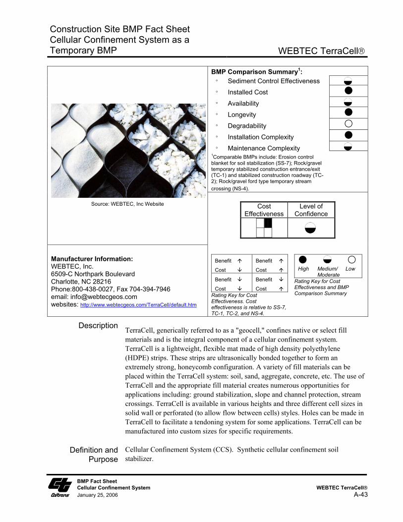
Construction Site BMP Fact Sheet Cellular Confinement System as a Temporary BMP
WEBTEC TerraCell
BMP Comparison Summary1: ° Sediment Control Effectiveness
° Installed Cost
° Availability
° Longevity
° Degradability
° Installation Complexity
° Maintenance Complexity 1Comparable BMPs include: Erosion control blanket for soil stabilization (SS-7); Rock/gravel temporary stabilized construction entrance/exit (TC-1) and stabilized construction roadway (TC-2); Rock/gravel ford type temporary stream crossing (NS-4).
Source: WEBTEC, Inc Website
Cost Effectiveness
Level of Confidence
Manufacturer Information: WEBTEC, Inc. 6509-C Northpark Boulevard Charlotte, NC 28216 Phone:800-438-0027, Fax 704-394-7946 email: [email protected] websites: http://www.webtecgeos.com/TerraCell/default.htm
Benefit
Cost
Benefit
Cost Benefit
Cost Benefit
Cost Rating Key for Cost Effectiveness. Cost effectiveness is relative to SS-7, TC-1, TC-2, and NS-4.
High Medium/ Low Moderate
Rating Key for Cost Effectiveness and BMP Comparison Summary
Description TerraCell, generically referred to as a "geocell," confines native or select fill materials and is the integral component of a cellular confinement system. TerraCell is a lightweight, flexible mat made of high density polyethylene (HDPE) strips. These strips are ultrasonically bonded together to form an extremely strong, honeycomb configuration. A variety of fill materials can be placed within the TerraCell system: soil, sand, aggregate, concrete, etc. The use of TerraCell and the appropriate fill material creates numerous opportunities for applications including: ground stabilization, slope and channel protection, stream crossings. TerraCell is available in various heights and three different cell sizes in solid wall or perforated (to allow flow between cells) styles. Holes can be made in TerraCell to facilitate a tendoning system for some applications. TerraCell can be manufactured into custom sizes for specific requirements.
Definition and Purpose
Cellular Confinement System (CCS). Synthetic cellular confinement soil stabilizer.
BMP Fact Sheet Cellular Confinement System WEBTEC TerraCell January 25, 2006 A-43
Construction Site BMP Fact Sheet Cellular Confinement System as a Temporary BMP
WEBTEC TerraCell
Appropriate Applications
■ Temporary Stream Crossing: Temporary ford type stream crossing in dry washes or ephemeral streams in arid areas during non-rainy season as described in NS-4. CCS are appropriate for streams that would benefit from an influx of gravel.
■ Ground stabilization, load support and tracking control at temporary stabilized construction entrance/exit, temporary construction access roads, and parking/storage areas.
■ Temporary slope stabilization, protection and revegetation on slopes (generally between 1V to 3H and 1V to 1H).
Advantages ■ Once expanded to its maximum extension and filled in with soil or gravel the CCS becomes inextensible and monolithic, providing an effective means of confinement for unconsolidated materials lying within single cells and preventing their movement even on steep slopes, or also from substantial dragging forces such as those exerted by sheet runoff.
■ Reduces runoff and sediment transport by confining soils within geocells. All cells are hydraulically interconnected and the CCS attains good permeability, facilitates the absorption of water during precipitation, diminishes surface runoff and consequently erosion.
■ Fords are the least expensive of the temporary stream crossing options outlined in NS-4. Relatively little rock or gravel is needed because the CCS provides the stability. For temporary fords, the CCS can be filled with natural river gravel, which may be a benefit to the stream upon removal of the CCS.
■ Improves soil structure and increases load support. Gravel/rock thickness may be reduced on temporary access road because CCS provides additional support. Use of a geocell can significantly reduce the amount and/or quality of aggregate required to stabilize a poor load bearing soil. If the temporary construction access road alignment is identical to a permanent roadway, use of the CCS may benefit the roadway section design. Note that use of CCS for both temporary and permanent applications at the same installation requires that it be designed accordingly and shown as such on both the Water Pollution Control Drawings and the Project Construction Drawings.
■ Possible alternative to removal/replacement of soft, poor soils along temporary access road routes and storage/parking areas.
■ Reduces formation of rills, gullies, and channels.
■ Lightweight and easy to transport.
■ For slope stabilization, CCS can be vegetated and thus serve both as a temporary and permanent BMP. Can minimize compaction and fill import. Note that use of CCS for both temporary and permanent soil stabilization
BMP Fact Sheet Cellular Confinement System WEBTEC TerraCell January 25, 2006 A-44
Construction Site BMP Fact Sheet Cellular Confinement System as a Temporary BMP
WEBTEC TerraCell
BMP applications at the same installation requires that it be designed accordingly and shown as such on both the Water Pollution Control Drawings and the Project Construction Drawings. If it is not called out on the plans as a permanent soil stabilization BMP, construction site inspectors may call for its removal at completion of construction.
Limitations ■ For slope stabilization applications CCS are more expensive than other erosion control measures due to labor and material costs. Typically this system is used as a permanent slope soil stabilization BMP in areas where other BMPs are not appropriate.
■ Not suitable for temporary use as channel slope protection in channelized flow conditions with moderate to high velocities (greater than 4-6 ft/s), particularly when using soil infill. Permanent applications of CCS in channelized flow conditions may be acceptable when appropriately designed.
■ Not suitable for temporary ford type stream crossings during rainy season or in perennial streams. CCS must be removed from stream upon completion of construction.
■ Not to be used on solid rock slopes. Maximum slope 1V to 1H.
■ Fill material within cells may be washed out in steep slope application if temporary cover with an SS-7 Rolled Erosion Control Product is not provided.
■ Erosion control effectiveness is highly dependent upon proper installation. Requires proper pins and anchors to secure in place. If there is a long slope upstream, a diversion ditch is recommend upslope of the CCS.
■ Typically it is not cost effective to reuse CCS since the majority of the installation cost consists of equipment and labor.
Effectiveness ■ Relative effectiveness compared to SS-7 (Rolled Erosion Control Products) used in a temporary slope stabilization application is Low to Moderate, since an interim SS-7 product is typically required to cover the CCS soil until vegetation is established.
■ Relative effectiveness compared to temporary stabilized construction entrance/exit (TC-1) and stabilized construction roadway (TC-2) is Moderate to High, since the CCS provides enhanced ground stabilization and load support while using less volume of aggregate fill material.
■ Relative effectiveness compared to a gravel/rock ford type temporary stream crossing per NS-4 is Moderate to High since the CCS provides enhanced stability with less gravel/rock material.
BMP Fact Sheet Cellular Confinement System WEBTEC TerraCell January 25, 2006 A-45
Construction Site BMP Fact Sheet Cellular Confinement System as a Temporary BMP
WEBTEC TerraCell
Cost and Availability
■ Relative installed cost compared to SS-7 (Rolled Erosion Control Products) is Moderate to High. Relative cost is high compared to biodegradible rolled erosion control products and Moderate to High compared to non-biodegradible erosion control products.
■ Relative installed cost compared to TC-1 is Medium and to TC-2 is Moderate to High. However, cost savings may be realized, and relative costs low, if use of CCS eliminates the need for removal and replacement of poor soils.
■ Relative installed cost compared to rock/gravel ford type temporary stream crossing per NS-4 is Moderate.
■ Production Rate/Installation Cost is High: $1.00 - $1.80/ft2 ($45,000 - $78,000 per acre) for a typical slope protection or load support application using 3- to 4-inch deep cells. Installed costs of CCS is highly dependent on site conditions, project size, and local costs of infill materials, equipment, and labor.
■ Product availability, or delivery time, is Moderate (typically one week).
Standards and Specifications
Key Design Elements
■ Determine if use is temporary only or both temporary and permanent.
■ Determine temporary application type and compare to other systems and materials based on site conditions to determine most cost effective system that provides the required amount of erosion protection.
■ Stability analysis for slope applications.
■ Required thickness or depth of CCS.
■ Required site preparation and requirement for geotextile underlay/overlay.
■ Hydraulic flow condition (sheet flow or channelized flow and expected flow velocities). Determine if upstream areas will contribute concentrated flow to CCS.
■ Infill material (soil or gravel).
■ Anchor pin spacing and anchoring system.
Materials
TerraCell is available if three cell sizes and several heights in black, tan and green. TerraCell is manufactured from High Density Polyethylene (HDPE) to the following minimum standards:
BMP Fact Sheet Cellular Confinement System WEBTEC TerraCell January 25, 2006 A-46
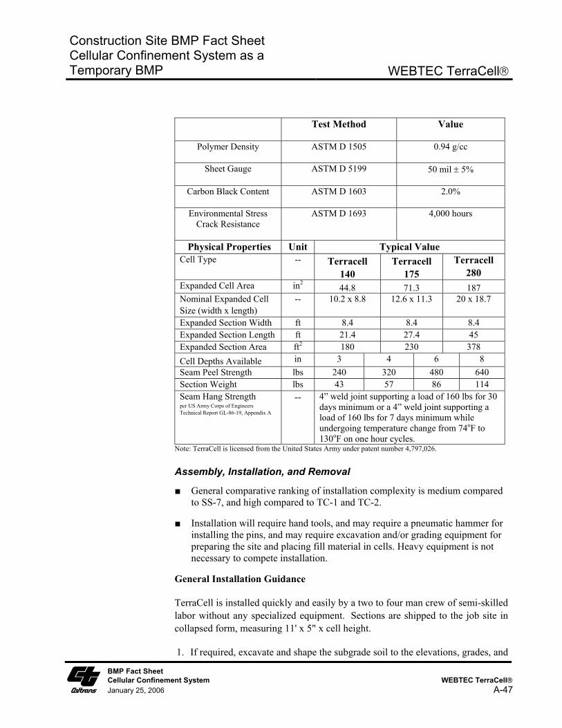
Construction Site BMP Fact Sheet Cellular Confinement System as a Temporary BMP
WEBTEC TerraCell
Test Method Value
Polymer Density ASTM D 1505 0.94 g/cc
Sheet Gauge ASTM D 5199 50 mil ± 5%
Carbon Black Content ASTM D 1603 2.0%
Environmental Stress Crack Resistance
ASTM D 1693 4,000 hours
Physical Properties Unit Typical Value Cell Type -- Terracell
140 Terracell
175 Terracell
280 Expanded Cell Area in2 44.8 71.3 187 Nominal Expanded Cell Size (width x length)
-- 10.2 x 8.8 12.6 x 11.3 20 x 18.7
Expanded Section Width ft 8.4 8.4 8.4 Expanded Section Length ft 21.4 27.4 45 Expanded Section Area ft2 180 230 378 Cell Depths Available in 3 4 6 8 Seam Peel Strength lbs 240 320 480 640 Section Weight lbs 43 57 86 114 Seam Hang Strength per US Army Corps of Engineers Technical Report GL-86-19, Appendix A
-- 4” weld joint supporting a load of 160 lbs for 30 days minimum or a 4” weld joint supporting a load of 160 lbs for 7 days minimum while undergoing temperature change from 74oF to 130oF on one hour cycles.
Note: TerraCell is licensed from the United States Army under patent number 4,797,026.
Assembly, Installation, and Removal
■ General comparative ranking of installation complexity is medium compared to SS-7, and high compared to TC-1 and TC-2.
■ Installation will require hand tools, and may require a pneumatic hammer for installing the pins, and may require excavation and/or grading equipment for preparing the site and placing fill material in cells. Heavy equipment is not necessary to compete installation.
General Installation Guidance
TerraCell is installed quickly and easily by a two to four man crew of semi-skilled labor without any specialized equipment. Sections are shipped to the job site in collapsed form, measuring 11' x 5" x cell height.
1. If required, excavate and shape the subgrade soil to the elevations, grades, and
BMP Fact Sheet Cellular Confinement System WEBTEC TerraCell January 25, 2006 A-47
Construction Site BMP Fact Sheet Cellular Confinement System as a Temporary BMP
WEBTEC TerraCell
BMP Fact Sheet Cellular Confinement System WEBTEC TerraCell January 25, 2006 A-48
dimensions as shown on the drawings.
2. If the fill material is different from the sub-base material, a geotextile should be used as a separator. A woven or nonwoven fabric is selected depending on whether strength or permeability is important. Simply unroll the geotextile directly on the subgrade, overlapping adjacent panels by 18" (minimum).
3. Determine where the first section of TerraCell is to be placed and put stakes at the four corners (typically an 8' x 20' area).
4. Stretch a section beyond its intended length and then allow it to relax. Place the section over the embedded stakes. Additional stakes may be needed along the perimeter in order to get full expansion of each cell. In situations where it is not practical to use stakes (over rocky soil, etc.), an installation frame may be needed. Adjacent sections are installed in a similar fashion and butted or stapled together to achieve continuous coverage.
5. Fill the first rows of cells with a front-end loader or dump truck and push the fill into cells using shovels or a bull-dozer blade. A "ramp" of fill material immediately adjacent to the TerraCell will likely be necessary to allow equipment to climb onto the geocell. Continue until all cells are filled. Never allow any equipment to drive over unfilled cells. Always overfill the cells slightly to allow for consolidation.
6. Next, it is necessary to compact the TerraCell system. For ground stabilization applications the most common method of compacting is through multiple passes by the tracked equipment used to spread the infill. A vibrating roller and/or water may be required to achieve the specified level of compaction. For soil stabilization and erosion control applications where the slope or channel will be revegetated the soil infill material should not be compacted over 85%.
Removal Removal of the system requires removal of the pins and anchoring system. Typically it is easier to install a new system than remove and re-use an existing system.
Maintenance and Inspection
■ Maintenance and inspection level of effort is Medium.
■ Inspect weekly in winter for slope instability. Typically, redirect water from rills, fill rills with soil, compact soil in cells, and secure with erosion control blanket or top with mulch if necessary. Inspect anchoring system at top and toe, pins, erosion of material from the cells.
Literature Sources ■ WEBTEC TerraCell product data sheet and website. ■ Caltrans, 2003. Caltrans Erosion Control New Technology Report, CTSW-
RT-03-049. ■ Caltrans, 2002. Project Planning and Design Guide.