Embed Size (px)
Citation preview
Am 81999
SANDIA REPORT’
)rv oDerated by Sandia Corporation,
Cells byAlkanes in
m G. Sault, Andy C. Y.”Tsai,
e
*
Issued by Sandia National Laboratories, operated for the United States Depart-ment of Energy by Sandia Corporation.
NOTICE This report was prepared as an account of work sponsored by anagency of the United States Government. Neither the United States Govern-ment, nor any agency thereof, nor any of their employees, nor any of theircontractors, subcontractors, or their employees, make any warranty, expressor implied, or assume any legal liability or responsibility for the accuracy,completeness, or usefulness of any information, apparatus, product, or processdisclosed, or represent that its use would not infringe privately owned rights.Reference herein to any specific commercial product, process, or service bytrade name, trademark, manufacturer, or otherwise, does not necessarilyconstitute or imply its endorsement, recommendation, or favoring by theUnited States Government, any agency thereof, or any of their contractors orsubcontractors. The views and opinions expressed herein do not necessarilystate or reflect those of the United States Government, any agency thereof, orany of their contractors.
Printed in the United States of America. This report has been reproduceddirectly from the best available copy.
Available to DOE and DOE contractors fromOffice of Scientific and Technical InformationP.O. BOX 62Oak Ridge, TN 37831
Prices available from (703) 605-6000Web site: http: ilwww.ntis.govlordering.htm
Available to the public fromNational Technical Information ServiceU.S. Department of Commerce5285 port Royal RdSpringfield, VA 22161
NTIS price codesPrinted copy: A04Microfiche copy: AO1
DISCLAIMER
Portions of this document may be illegiblein electronic image products. Images areproduced from the best available originaldocument.
SAND 99-0681Unlimited ReleasePrinted April 1999
.
.
Hydrogen Production for Fuel Cells by SelectiveDehydrogenation of Alkanes in Catalytic Membrane Reactors
Timothy J. Gardnerand Allen G. SaultNew Materials and Validation Department
Elaine.P. BoespflugExplosive Materials/SubsystemsDepartment
C. Jeffrey BrinkerDirect FabricationTechnologies Department
SandiaNational LaboratoriesP.O. BOX 5800
Albuquerque, NM 87185-0710
Andy C. Y. TsaiAdvanced Materials Laboratory
University of New MexicoAlbuquerque, NM 87131
John P. CollinsAmoco Research CenterNapierville, IL 60563
Abstract
Hydrogen-powered polymer electrolyte membrane (PEM) fiel cells, fueled by on-board H2generation from liquid fiels, represent a potential enabling technology for future vehicles.Much currenteffort has been devoted to the use of stem reforming or partial oxidation ofliquid fuels for on-board H2generation,but these technologies generatelarge amounts of CO,which can poison PEM fiel cells. The purpose of this project was to develop a catalyticmembrane reactor system for the generation of pure H2 via selective dehydrogenation ofliquid fiels. Separation of hydrogen from hydrocarbons was to be achieved by modificationof commercial asymmetric aluminamembrane tubes with permselective microporous ceramicmembranes. Hydrous titanium oxide (HTO) and silica-doped hydrous titanium oxide(HTO:Si) ion exchange materialswere evaluatedas a component of the microporous ceramic -composite membrane material and as a support for bulk dehydrogenation catalysts,
3
respectively. Finally, experiments were petiormed using a bulk dehydrogenation catalyst inconjunction with a microporous ceramic membrane to demonstratea proof of concept for H2generation by n-heptane dehydrogenation/dehydrocyclization using a catalytic membranereactor. This scheme offers a potential method for increasing hydrogen production rateswithout increasing reactor size by overcoming equilibrium limitations on conversion, animportantconsideration for transportationapplications or for remote electricityy generation forcivilian or military applications.
●
●
Acknowledgment
The authors thank United Catalysts, Inc. for stimulatingtechnical discussions and for providingsamples of commercial dehydrogenation catalysts. The efforts of Tim Boyle in preparingorganometallic tin precursors for use in Pt-Sn catalystpreparation, as well as the overall catalystpreparation and characterizationefforts of Linda McLaughlin, are gratefidly acknowledged. Thiswork was supported by the United States Department of Energy under Contract DE-AC04-94AL85000. Sandia is a multiprogram laboratory operated by Sandia Corporation, a LockheedMartin Company, for the United StatesDepartmentof Energy. This report summarizes activitiesperformed under the laboratory directed research and development program at Sandia NationalLaboratories (project number 96-0396).
b
.
4
Contents
b
0
htioduction ......................................................................................................................................8ChapterI. Membrane Development Effotis ...................................................................................l3
Experimental ..........................................................................................................................l3Results and Discussion ...........................................................................................................l5Summary.................................................................................................................................23
ChapterII. Bulk CatalystDevelopment Effofis .............................................................................23Experimental ..........................................................................................................................23Results and Discussion ...........................................................................................................26
PreliminaryIsooctane Dehydrogenation Screening Experiment .......................................26HeptaneDehydrogenation/Dehydrocyclization Experiments...................._ ......................27
Supported Cr Catalysts.................................................................................................28Commercial Benchmark Catalyst- Girdler G-41 Cr/y-AlzOs...........................-....29Cr~TO:Si Catalysts..............................................................................................3l
Pt-BasedlHTO:Si Catalysts..........................................................................................37summary ..................................................................................................................................45
ChapterIII.Catalytic Membrane Reactor Testing .........................................................................46Experimental..........................................................................................................................46Results ad Discussion ...........................................................................................................47summary.................................................................................................................................54
Overall Summaryand Recomendations ......................................................................................55References......................................................................................................................................56
Figures
1.
2.
3.
4.
5.
Conceptual on-board H2generation/fuelcell system (after ref. [4]). The large boxencompassing the reforming, water gas shift, and Hz purification stepsrepresentsthat,portion of an on-board H2generation/fuelcell system which could potentiallybe replaced bya catalyticmembrane reactor. The reformerprocess unit shown could utilize either a partialoxidation or a steam reforming reaction for H2generation......................................................9Catalyticmembrane reactor concept for selective dehydrogenation of alkanes. The packedcatalystbed would completely occupy the annularspace inside the tubularmembrane (notshown for simplici&) ..............................................................................................................l OSchematic illustration of gradedporosity tubularmembrane shown in Figure 2. Themolecular sieving layer can be a baseline silica membrane or a composite membrane thatconsists of additional layersdeposited on thebaseline silica membrane,which tailor theporesize and resulting perrnselectivityof the membrane. As illustratedin Figure 2, the annularspace of the membrane tube would be filled with a packed catalystbed for a catalyticmembranereactor application. ...............................................................................................l2Low temperaturesingle gas permeance measurementresults for baseline silica microporousmembranes and HTO/silica composite membranes. For simplicity, the HTO/silica compositemembranehas been denoted as HTO/Si02 in the legend associated with the Figure. ...........15TEM photomicrograph showing a cross-section view of an HTO/silica compositemembrane deposited on a commercial asymmetric aluminamembranetube. .......................16
5
6. High temperaturesingle gas perrneancemeasurementsfor baseline silica membranes.........177. TEM photomicrograph of a surfactant-templatedsilica fihn as viewed along the [100]
zone axis. This photomicrograph demonstratesthatthe material consists of an orderedcubic liquid crystallinemesostructure..........................................-.........................................l8
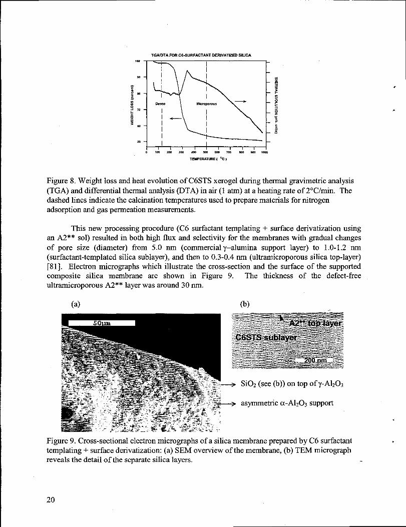
8. Weight loss and heat evolution of C6STS xerogel during thermal gravimetricanalysis(TGA) and differential thermal analysis (DTA) in air (1 atm) at a heatingrateof 2°C/min.The dashed lines indicate the calcination temperaturesused to preparematerials fornitrogen adsorption and gas permeation measurements..-......................................................2O
9. Cross-sectional electron micrographs of a silica membrane preparedby C6 surfactanttemplating+ surface derivatization: (a) SEM overview of the membrane, (b) TEMmicrograph reveals the detail of the separatesilica layers......................................................2O
10. Molecular sieving behavior of an A2** sol-derivatized C6STS membrane calcined at450”C for 1 h in air. The ideal separationfactor, cq, representstheratio of permeancevalues (measured in single gas permeance tests) for the two specified gases. .......................22
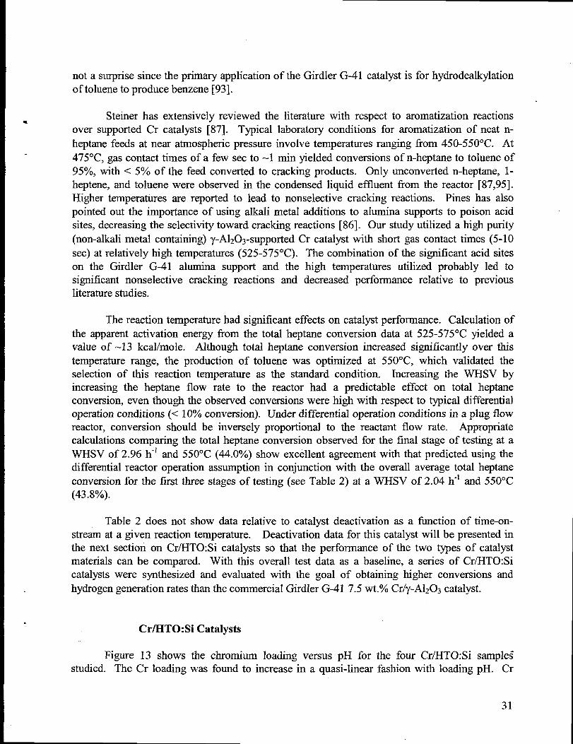
11. Schematic diagram of conventional packed bed dehydrogenation reactor..........._ ................2612. Net chemical reaction for dehydrogenation/dehydrocyciization of n-heptaneto toluene. .....2713. Variation of chromium loading on HTO:Si supportswith pH used duringthe cation
exchange procedure. ............................................-..................................................................3214. Initialtotal and specific (per g Cr) heptanedehydrogenation/dehydrocyclization activity of
Cr/H.TO:Si and Girdler G-41 7.5 wt.% Cr/y-A1203catalysts at 550”C, WHSV = 2.0 h-l.Filled symbols correspond to total heptaneconversion datawhile open symbols correspondto specific heptaneconversion data. Circularsymbols correspond to Cr/HTO:Si catalystdatawhile square symbols correspond to the Girdler G-41 catalystdata...............................33
15. Total heptane conversion as a function of time-on-stream at 550”C and a nominal WHSVof 2 h-’ for the Girdler G-41 7.5 wt.OACr/y-A1203(square symbols) and the 2.65 Wt. O/O
Cr/HTO:Si (circular symbols) catalystsbefore and after air regeneration. Open symbolsrepresentinitial catalystdeactivation and filled symbols representcatalystdeactivationafterone airregenerationtreatmentat 55OOC.........................................................................36
16. Initialdata for total heptaneconversion as a fi.mctionof time-on-stream at 550°C and anominal WHSV of 2 h-] for the Pt-based/HTO:Si catalysts. The following catalystsarerepresented: Pt/HTO:Si (open circular symbols), Pt-Re/HTO:Si (open squaresymbols),andPt-Sn/HTO:Si (open triangularsymbols). ..............--.......................-....-..................-.......43
17. Data for total heptane conversion after one regenerationcycle as a fimction of time-on-streamat 550”C and a nominal WHSV of 2 h-l for the Pt-based/HTO:Si catalysts.Thefollowing catalystsarerepresented: Pt/HTO:Si (filled circular symbols), Pt-Re/HTO:Si(filled squaresymbols), and Pt-SnIHTO:Si (filled triangularsymbols). As a reference,the open circular symbols representthe initialcatalyst deactivation datafor the Pt/HTO:Sicatalyst(from Figure 16). The regenerationcycle consisted of a N2purge for 10 min at550”C, followed by an air treatmentfor 10 min at 550”C, followed by a H2treatmentat 550°C for 30 min. ...............................................................................................................44
18. H2generationversus time-on-stream for the catalytic membrane reactor operated at variousWHSV values with the Girdler G-41 7.5 wt.% Cr/y-A1203 catalyst. For these experiments,the reactor temperaturewas 550”C and the tube side pressure (PJ was 1 atm. See footnotesfor Table 4 for a definition of the H2 generationrate/heptanefeed rateterm. .......................50
6
e
*
19. H2and N2 permeance values at 525°C versus time-on-stream for composite silicamembraneused in heptanedehydrogenatiorddehydrocyclizationcatalytic membranereactor study. ..........................-................................-...................-...............................-..........52
9
Tablesw
1.2.
3.
4.
5.
&
.
Permeancesof components of a simulatedreformate product gas mixture at 80”C. ...............22Heptanedehydrogenation/dehydrocyclization resultsobtained with the Girdler G-417.5 wt.Yo Cr/y-A1203catalyst. ...................................................-..............................................3OHeptanedehydrogenation/dehydrocyclization resultsobtained with the Pt-based/HTO:Sicatalysts. ...................................................................................................................................39Catalyticmembrane reactorresultsobtained with the Girdler G-41 7.5 wt.Yo Cr/y-A1203catalystused in conjunction with a composite silica membrane for heptanedehydrogenation/dehydrocyclization. Catalystactivity and selectivity resultswere obtainedas a fimction of WHSV at a tube side pressure(Pt) = 1 atm, a reactor temperatureof 550”C,and 60 min nominal time-on-stream............................................................-...........................48Catalyticmembrane reactorresultsobtained with the Girdler G-41 7.5 wt.% Cr/y-A1203catalystused in conjunction with a composite silica membrane for heptanedehydrogenation/dehydrocyclization. H2 generationand permeation rateswere obtained as afimction of tube side pressure(Pt) at a WSHV of 8 h-’, a reactor temperatureof 550”C, and60minnominal time.on.stieam ...............................................................................................5l
7
Hydrogen Production for Fuel Cells by SelectiveDehydrogenation of Alkanes in Catalytic Membrane Reactors
Introduction
The need for increased energy efficiency and decreased environmentalemissions providesa strong driving force for research into alternatives to the internal combustion engine fortransportationneeds. One promising alternatetechnology is electricity-generatingfuel cells [l-3]. Pure H2 fuel for these systems is very compatible with the current polymer electrolytemembrane (PEM) technology [1-3]. However, safely storing hydrogen with energy densitiessufficient to provide adequate vehicle range currently represents an important obstacle to thesuccessful utilization of H2-powered fuel cells [4]. A potential solution to this difficulty involveson-board generation of H2 from liquid fuels, thereby solving fiel storage problems andsimultaneously taking advantageof the existing infrastructurefor distributionof liquid fuels. Forhybrid vehicles [5,6], on-board H2 generation would allow the same liquid fuel to be used topower both an internal combustion engine and a fiel cell, thereby avoiding weight and spacepenalties associated with separate fhel storage systems. A wide range of chemical processes(jximarily steam reforming and partial oxidation) have been proposed for on-board reforming ofvarious liquid fuels (gasoline, diesel fuel, methanol, etc.) to produce H2 for PEM fuel-cellpowered vehicles [4,7-1 1]. The focus of this project was the development of a catalyticdehydrogenation membrane reactor to generate H2 from liquid hydrocarbons (alkanes) andsimultaneously separatethe H2from the olefin coproducts.
The selective dehydrogenation scheme we propose also provides advantages over steamreforming, another prospective on-board H2 production scheme. On-board steam reformingrequires extensive water management that is absent with dehydrogenation. Dehydrogenationtherefore avoids the weight and space penalty associated with the need to pump, store, andrecycle water for steam reforming. Steam reforming also generates substantialamounts of COand C02, which wastes a large fraction of the available energy content of the fuel. The presenceof CO represents a serious problem since it has a significant poisoning effect on PEM fuel cells ifit is not rigorously removed. In addition to H2, selective dehydrogenation generates onlyhydrocarbons (olefins) that are easier to separate iiom H2 than CO and C02, that are not severepoisons for PEM I%el cells, and that can be collected and reused as fuel for an internalcombustion engine or to generateheat to drive the endothermic dehydrogenationreaction.
Steam reforming is also endothermic, requiring large heat input, so the endothermicnature of dehydrogenation is not necessarily a disadvantagerelative to reforming- Offsetting theimportant advantagesof dehydrogenation is the fact thatsteam reforming recovers virtually all ofthe hydrogen in the fuel as H2, while in dehydrogenation a substantialfraction of the hydrogenremains in the dehydrogenatedproducts. Thus, a dehydrogenation unitwill likely require a largerthroughput than a steam reforming unit to produce comparable amounts of H2. We believe thatother advantages offered by dehydrogenation more than offset this disadvantage, with the netresult being a smaller and more efficient on-board H2 generation unit. While partial oxidation
8
.
.
.
.
.
.
.
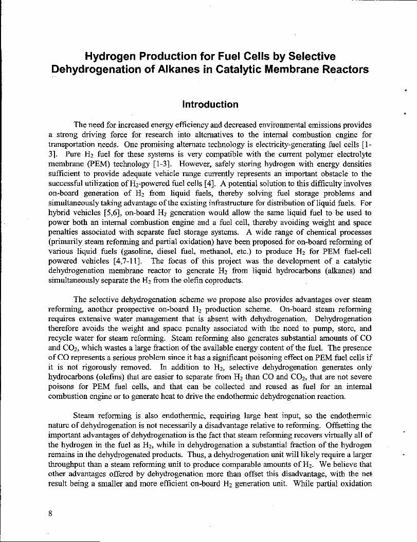
reactions.are exothermic in nature,such reactions are difficult to control such thatCO and H2 areselectively produced without the formation of combustion by-products (C02 and H20). Aconceptual on-board H2generatiordfiel cell system is illustratedbelow in Figure 1.
Fuel + air/water
t
Reformer
t
~ “’’r”’”’
nHzPurification
A.Heat
BurnerI Amde~aS I
H2 in
v
m uElectricPower
~-”
Figure 1. Conceptual on-board H2generationhiel cell system (afterref. [4]). The largeboxencompassing the reforming, water gas shift, and H2purification steps representsthatportion ofan on-board H2 generation/fuel cell system which could potentially be replaced by a catalyticmembranereactor. The reformer process unit shown could utilize eithera partialoxidation or asteamreforming reaction for H2generation.
Many authors have provided reviews of catalytic membrane reactors, pointing out theirpotential advantages and current limitations [12-20]. Since many chemical reactions arereversible in nature (e.g., hydrogenation/dehydrogenation), conversions which can be achieved toproduce a given-product slate are equilibrium limited. However, catalytic membrane reactorsthat combine selective separation (i.e., permselectivity) of a given product species with thechemical reaction can lead to increased reactant conversion to the desired products. Likewise,potentially unfavorable secondary reactions involving product species can be limited by selectiveproduct species removal. Other possible advantages are related to increased catalyst life,simplified downstream separationand recovery operations, overall energy savings, and increasedstiety through control of reactant feed in difficult-to-control reactions (e.g., regulation of 02addition for oxidative dehydrogenationversus uncontrolled combustion).
In the case of on-board reforming for Hz generation, the advantagerelated to simplifieddownstream separation and recovery operations is a significant one. It is well known thatmoreconventional steam reforming or partial oxidation of hydrocarbon feeds will produce PEM fhelcell feedstocks thatrequire significant H2purification. Figure 1 shows thata number of separatechemical processes arerequired for CO removal, including both low and high temperaturewater-gas shift (CO + H20 = H2 + C02) [9,21], and additional H2 purification (e.g., preferentialoxidation [PROX] of CO in the presence of H2) [9-1 1,22-24]. CO concentrations need to bereduced from nominally 1 0/0 (molar or volume basis) in the post-water gas shift streamto <40
9
ppm (< 10 ppm is desirable) in the final fuel cell feedstock to avoid detrimentallyaffecting fuelcell petiormance [1, 25]. The use of a membrane with high permselectivity to H2 (H2/C0separation factor > 1000) could greatly simplify the overall process for H2 generation andpurification by replacing these additional chemical process units, as well as simultaneouslyremoving other potential contaminant species fi-om the PEM fuel cell feedstock. As illustratedby the largebox in Figure 1, a catalytic membranereactor system could replace the reformer unit,water-gas shiftunit(s), and additional H2purification (PROX) unit.
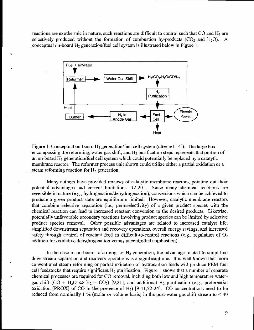
In particular,the application of permselective membranes for stand-alone H2 purification[12-20,26-45] or catalytic membrane reactors in which H2 generation reactions (dehydrogenation,reforming, etc.) are utilized [12-20,46-61 ] has recently received considerable interest. Theattributes and fundamental mechanisms involved in gas separation using permselective densemetal (Pal) [12-20], polymeric [30,3 1], or microporous ceramic [32-39] (including zeolites [40-45]) membraneshave been reviewed in detail elsewhere. Microporous ceramic membranes, withthe combined attributes of low cost and high temperature (> 200”C) stability, relative to Pdmembranes and polymeric membranes, respectively, show enormous potential for fiture catalyticmembrane reactor or membrane separation applications. Finally, the combination of catalysisand separationfi.mctionalitieswithin a single systemalso offers a unique opportunityto minimizeweight and volume requirements for chemical processes, which is of premier importance inautomotive applications. This background indicated that catalytic membrane reactors utilizingmicroporous ceramic membranes might well be an enabling technology for on-board generationof H2 for PEM fuel-cell powered vehicles. A schematic illustration of the catalytic membranereactor concept for alkane dehydrogenation is shown below in Figure 2.
Graded Porosity
Sweep Gas Hz Tubular Membrane
t t t I
Reactor Feed
Aikane -
Catalyst /Particles
+Nonporous wall of membrane reactor module
Residue \(Alkenea,Non-Selective Products)
Figure 2. Catalytic membrane reactor concept for selective dehydrogenationof alkanes. Thepacked catalystbed would completely occupy the annularspace inside the tubularmembrane (no~shown for simplicity).
10
The catalystimembrane system employed in our studies is based upon commercially-available asymmetric aluminamembrane tubes with 5 nm average pore diameters [62], modifiedwith a microporous ceramic membrane (made up of one or more deposited layers of variousmaterials) that impartshigh H2 selectivity and permeability. Hydrous titaniumoxide (HTO)- or.silica-doped hydrous titaniumoxide (HTO:Si)-supported Fe and Cr catalysts have demonstratedsubstantial activity for both ethylbenzene and isobutane dehydrogenation and are likely
. candidates for other alkane dehydrogenation reactions [63,64]. Part of our studies focus on theevaluation of bulk HTO:Si-supported catalysts in packed catalyst beds tested in a stand-alonemode or in conjunction with microporous ceramic membranes. The former testswill be referredto as conventional packed bed reactor experiments, while the latter tests will be referred to as
‘ catalyticmembrane reactor experiments.
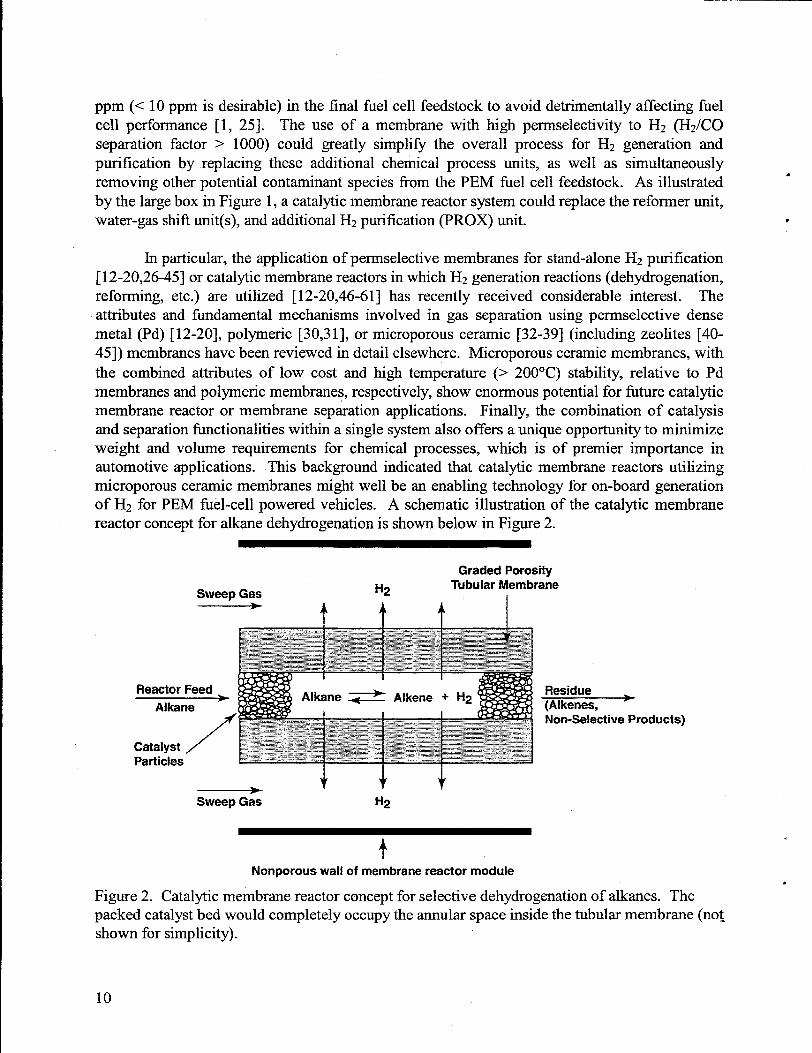
In addition to high catalystactivity in bulk catalystapplications (conventional packed bedreactors), HTO- or HTO:Si-supported catalyst materials can provide a distinct advantage overcommercial dehydrogenation catalysts in that they can be cast as thin films on virtually anysubstrate[65,66]. Our planned approach was to first modifi a commercial asymmetric aluminamembrane tube (non-hydrogen selective) with a baseline microporous silica layer. In addition toevaluating these membrane materials in baseline silica form, composite microporous ceramicmaterialswere also evaluated. In previous studies, several materials have been evaluated in thecomposite membranes as separatelayers deposited onto the baseline silica membrane, includingsilica (an additional layer with different sol chemistry and/or deposition conditions) and titania[34,67]. For this study, as an alternative to titania, a composite membrane was fabricated bydepositing a nanocrystalline,ion-exchangeable HTO or HTO:Si layer on top of the baseline silicamembrane surface. This approach utilized the underlying baseline silica membrane layer tomediate the delivery of water for hydrolysis and condensation reactions to an alkali titanateprecursor layer. The use of the HTO or HTO:Si coatings offers the advantage of allowing aproven catalytic fi.mctionto be incorporated into the membrane. We anticipatedthatthe intimateassociation of the membrane and catalyst obtained with this approach would result in improvedconversions relative to conventional membrane reactor schemes that use only a bulk catalyst(packed bed) inside the membrane tube. Furthermore, this composite coating approach isamenable to coating low cost, high surface areato volume ratio ceramic monoliths thatwould beideal supports for automotive fuel cell applications. A schematic illustration of the gradedporosity asymmetrictubularmembrane (see Figure 2) is shown in Figure 3.
*
11
/---
Molecular Sieving Layer
~ y- Alumina Layer
~ a- Aiumina Layer
‘n
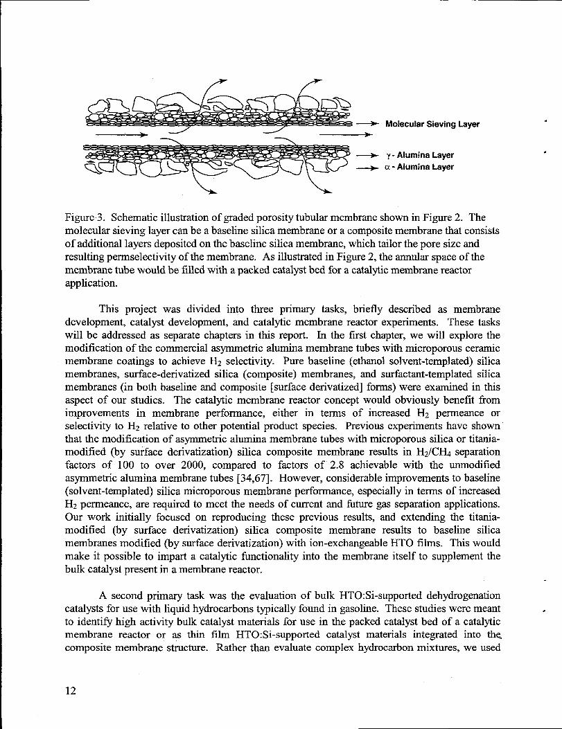
Figure3. Schematic illustrationof graded porosity tubularmembrane shown in Figure 2. Themolecular sieving layer can be a baseline silica membrane or a composite membrane thatconsistsof additional layers deposited on the baseline silica membrane, which tailor the pore size andresultingpermselectivity of the membrane. As illustratedin Figure 2, the annularspace of themembrane tube would be filled with a packed catalystbed for a catalyticmembrane reactorapplication.
This project was divided into three primary tasks, briefly described as membranedevelopment, catalyst development, and catalytic membrane reactor experiments. These taskswill be addressed as separate chapters in this report. In the first chapter, we will explore themodification of the commercial asymmetric alumina membrane tubes with microporous ceramicmembrane coatings to achieve H2 selectivity. Pure baseline (ethanol solvent-templated) silicamembranes, surface-derivatized silica (composite) membranes, and surfactant-templatedsilicamembranes (in both baseline and composite [surface derivatized] forms) were examined in thisaspect of our studies. The catalytic membrane reactor concept would obviously benefit fromimprovements in membrane performance, either in terms of increased H2 permeance orselectivity to H2 relative to other potential product species. Previous experiments have shownthatthe modification of asymmetric alumina membrane tubes with rnicroporous silica or titania-modified (by surface derivatization) silica composite membrane results in H2/C~ separationfactors of 100 to over 2000, compared to factors of 2.8 achievable with the unmodifiedasymmetric alumina membrane tubes [34,67]. However, considerable improvements to baseline(solvent-templated) silica microporous membrane performance, especially in terms of increasedH2 perrneance, are required to meet the needs of current and fiture gas separation applications.Our work initially focused on reproducing these previous results, and extending the titania-modified (by surface derivatization) silica composite membrane results to baseline silicamembranes modified (by surface derivatization) with ion-exchangeable HTO films. This wouldmake it possible to impart a catalytic fmctionality into the membrane itself to supplement thebulk catalystpresent in a membrane reactor.
A second primary task was the evaluation of bulk HTO:Si-supported dehydrogenationcatalysts for use with liquid hydrocarbons typically found in gasoline. These studies were meantto identifi high activity bulk catalyst materials for use in the packed catalyst bed of amembrane reactor or as thin film HTO: Si-supported catalyst materials integratedcomposite membrane structure. Rather than evaluate complex hydrocarbon mixtures,
catalyticinto thewe used
.
12
.
model compounds, such as isooctane (2,2,4-trimethylpentane) or n-heptane, which havecharacteristicssimilar to those of gasoline. We previously investigatedthe use of Fe/HTO:Si andCr/HTO:Si catalysts for dehydrogenation of isobutane and ethylbenzene, and found that theoptimal catalyst formulations are similar for the two reactions [63,64]. We therefore anticipatedthat the use of known catalyst syntheses would yield highly active catalysts for isooctane or n-heptane dehydrogenation. Testing was performed to determine catalyst activity trends, reactantconversions, selectivities, and catalyst deactivation under various reaction conditions, and toinvestigate catalyst regeneration schemes. Catalyst synthesis and testing also included HTO:Si-supportednoble metal catalystsas well, since supported noble metal catalystsare used in severalcommercially important alkane dehydrogenation/dehydrocyclization reactions (e.g., platfonning,so named because it describes catalytic reforming reactions in which alkane components ofpetroleum-derived feeds are dehydrogenated and/or cyclized over platinum catalysts to producemore valuable [higher octane number] chemical compounds such as branched alkanes andaromatics) [68,69]. The HTO:Si-supported catalysts synthesized as part of this study wereevaluatedagainstan appropriatecommercial dehydrogenation catalystas a benchmark.
The third primary task involved joining the membrane and catalyst technologies in asingle unit, and testing the performance of the resulting catalytic membrane reactor system. H2production rates, H2purity, and hydrocarbon product distributionswere all measured. The abilityto incorporate a catalytic fiction directly into the membrane offered multiple options forconfiguring the reactor system. The focus of our efforts in this area involved the simplestpossible catalytic membrane reactor scheme, in which a microporous ceramic membrane-modified commercial asymmetric aluminamembrane tube was filled with a bulk catalyst.
Chapter L Membrane Development Efforts
Experimental
Membrane supports were prepared by sectioning commercial asymmetric 5 nm averagepore diameter alumina (y-A1203 /ct-A1203) membrane tubes (U.S. Filter,Membralox@) [62] into5.5 cm long sections, followed by ultrasonic cleaning in deionized water. These aluminamembrane tubes had an OD of 1 cm and an ID of 0.7 cm. The cleaned membrane supportswerethenwashed with deionized water several times before calcining at450°C for 1 h.
All silica membranes of the present study were prepared from an A2** sol [67]. TheA2** sol is a modification of the original A2 sol recipe developed by Brinker, et al. [70].Preparationof the A2** sol consists of two acid-catalyzed reaction steps designed to minimizethe condensation rates of silica species in order to produce weakly branched polymeric clustersthat interpenetrateand collapse during film deposition to produce membranes with molecular-sized pores. The two-step procedure results in a final molar ratio of tetraethyl orthosilicate(TEOS): ethanol: H20: HC1=1.0:3.8 :5.0:0.004 (pH = 2.0, standardsol). A dip-coating sol for
13
solvent (ethanol)-templated silica membraneswas prepared by diluting the standardsol with twotimes its volume of ethanol. For surfactant-templated silica membrane preparation, severalsurfactants were used. Some SOIS were prepared by adding a C6-surfactant(triethylhexylammoniumbromide) powder to unaged AZ** standardsol to obtain a C6-surfactantconcentration of 0.125 M prior to dilution. The resulting membranes were referred to as C6-surfactant templated silica (C6STS) sublayers. Other SOISwere prepared by adding a C16-surfactant (cetyltrimethylammonium bromide or CTAB) powder to aged and diluted (withethanol) A2** standardsol to obtain a final C16-surfactant concentration of 0.03-0.11 M (1.5-5wt.’%o).
A sol-gel dip-coating process featuringaspects of slip casting was performed under cleanconditions, including (but not restricted to) Class 100 clean room conditions. Baseline solvent(ethanol)-templated silica membranes were prepared using standarddip coating techniques (dipcoating rate = 7.6 cndmin) [71]. Surface derivatization was used to fiu-theralter some of theresulting microporous silica membranes, although an HTO-like soluble intermediate (composedof NaOH/methanol/ titanium isopropoxide sol in the appropriate stoichiometry to generate aNaTi205H ion exchanger) [72,73] was used in place of the pure titaniacoating solution (titaniumisopropoxide diluted in THF) utilized in previous studies [34,67]. Prior to the surfacederivatization step, the baseline silica layer was “pre-hydrolyzed” via soaking in deionized H20for 24 h. A second dip coating application was thenused to apply the HTO precursor (after a 30-fold dilution in THF), and the composite membranewas heated to 400”C for 3 h in air.
Surfactant-templatedsilica membranes were prepared using a multi-step procedure [74].For enhanced microstructural characterization, some samples were prepared by dip coatingmembranes onto single crystal silicon wafers ((100) orientation). To prepare actual surfactant-templated silica membranes for permeation testing, an asymmetric alumina membrane supporttube was dip-coated using a silica sol containing the surfactant as described above. Thestiactant-templated silica membraneswere calcined at 120”C for 1 h in air and were confirmedto be impermeable to helium. Surfactant removal was accomplished by heating the tube at500°C for 1 h in air. Some surfactant-templated silica membranes were further surfacederivatized to produce a composite membrane material. In this case, the as-prepared asymmetricalumina membrane support tube with a surfactant-templated silica membrane sublayer wasfiu-therdip-coated using an A2** sol (no added surfactant)using the standardcoating procedure.The as-coated membrane tube was heated under vacuum at a rate of 10C/min ftom roomtemperatureto 300”C. Permeation measurementswere conducted after performing a standardoutgassing procedure (He purge at 80”C for 3 h).
Corresponding bulk xerogels were produced from the same sol precursors as the varioussilica membrane materials for characterization by thermal gravimetric analysis (TGA),differential thermal analysis (DTA) and nitrogen sorption porosimetry. A surface acoustic wavetechnique (SAW) was used to determine pore accessibility of supported films [75]. Scanningelectron microscopy and transmission electron microscopy (TEM) were used to determine themorphology of membranes. Gas permeation measurements were performed in a pressure-controlled (AP = 80 psia) single gas or gas mixture mode without any sweep gases [67,76,77]:Flow rateswere measured using a digital bubble flow meter. Gas compositions of the permeate
.
14
>
b
and retentatewere analyzedby on-line gas chromatographyusing a thermalconductivity detector(TCD). The ideal separation factor (0$ for various gas pairs was calculated from the ratio ofindividual gas permeance values obtained ilom measurements with either single componentgases, equimolar binary gas mixtures, or a simulatedreformate feed (nominal composition: 50VO].YO H2, l?’o CO, 1570c02, and 34°4 N2).
.
Results and Discussion
Three major issues were initially addressed regarding the microporous silica ceramicmembrane technology integration of HTO films using a surface derivatization approach, hightemperature performance of baseline silica membranes, and reproducibility of membranefabrication.
Low temperature single gas permeance measurements were performed on thesemembranes both before and after HTO coatinglheattreatment. The resultsobtained before EITOcoating and heat treatmentare considered representativeof baseline silica membranes. Theseresults, shown below in Figure 4, demonstratethatthepermeance of all gases throughthe silica
q ()-3 1 I I I I I 1 I Ii
L
+!4=@& /4”—
‘z Ai- h“——— —
-1
I (3-6 i I i I I i I 1 I 1
0 50 100 150 200 250
Temperature (“C).
!&KS@-o- H2(Si02)+ H2 (HTO/Si02)+ N2(Si02)+ N2 (HTO/Si02)+ CHA(SiO.)–A- - CH~ (HTO/SiOJ
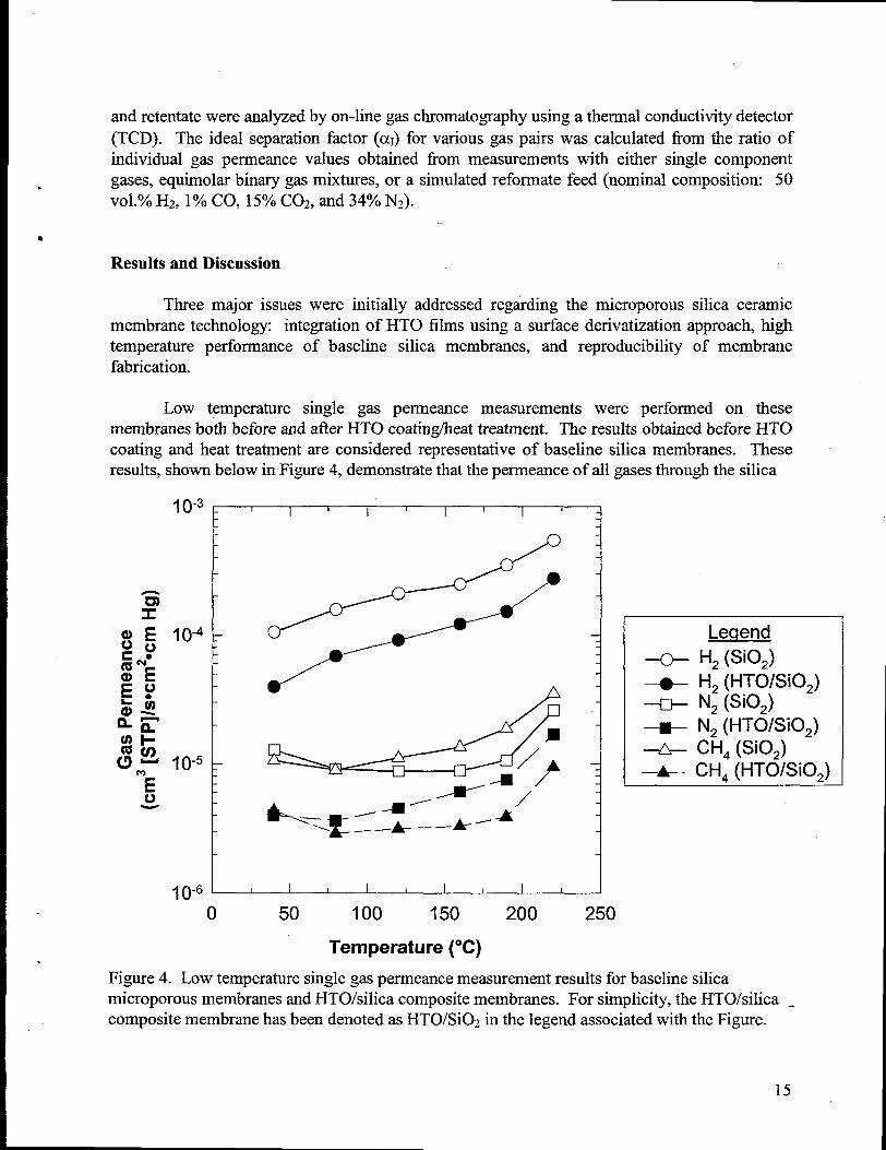
Figure 4. Low temperaturesingle gas permeance measurementresults for baseline silicamicroporous membranes and HTO/silica composite membranes. For simplicity, the HTO/silica -composite membrane has been denoted as HTO/Si02 in the legend associated with the Figure.
microporous membrane was decreased by the presence of the additional HTO layer. However,concurrent with this decrease in perrneance for the HTO/silica composite membrane is a slightincrease in the H2 selectivity, determined by the ratio of the single gas permeance values of H2versus the other gases (CH4 and N2). For example, the average ideal H2/CH4 separation factor(cxI) over the six data points shown in Figure 4 increased fi-om -22 for the baseline silicamembrane to -29 for the HTO/silica composite membranes. These results are consistent withmore recent results (not shown herein) for surface derivatization of baseline silica microporousmembranes via pure titaniacoatings.
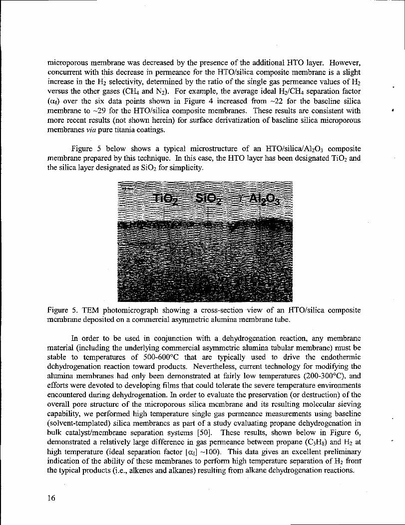
Figure 5 below shows a typical microstructure of an HTO/silica/A1203 compositemembrane prepared by this technique. In this case, the HTO layer has been designated Ti02 andthe silica layer designated as Si02 for simplicity.
Figure 5. TEM photomicrograph showing a cross-section view of an HTO/silica compositemembrane deposited on a commercial asymmetric aluminamembrane tube.
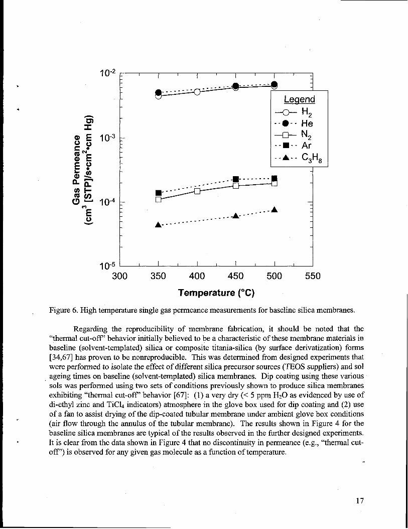
In order to be used in conjunction with a dehydrogenation reaction, any membranematerial (including the underlying commercial asymmetric alumina tubularmembrane) must bestable to temperatures of 500-600°C that are typically used to drive the endothermicdehydrogenation reaction toward products- Nevertheless, current technology for modifying thealumina membranes had only been demonstrated at fairly low temperatures (200-300°C), andefforts were devoted to developing films thatcould tolerate the severe temperatureenvironmentsencountered during dehydrogenation. In order to evaluate the preservation (or destruction) of theoverall pore structure of the microporous silica membrane and its resulting molecular sievingcapability, we perfomned high temperature single gas permeance measurements using baseline(solvent-templated) silica membranes as part of a study evaluating propane dehydrogenation inbulk catalystimembrane separation systems [50]. These results, shown below in Figure 6,demonstrated a relatively large difference in gas permeance between propane (C3Hg) and H2 athigh temperature (ideal separation factor [aI] -1 00). This data gives an excellent preliminaryindication of the ability of these membranes to perform high temperatureseparation of Hz fronfthe typical products (i.e., alkenes and alkanes) resulting from alkane dehydrogenationreactions.
16
.
.
j ()-2 - 1 I 1 I I I I I I
--------------------- -- 1
!&l@
-o- H2
-- O-- He-n- N2--~-. Ar
~
.-AA------
A------------------
I ()-5 I I I I I I I I !
300 350 400 450 500 550
Temperature (“C)
Figure 6. High temperaturesingle gas permeance measurementsfor baseline silica membranes.
Regarding the reproducibility of membrane fabrication, it should be noted that the“thermal cut-off” behavior initiallybelieved to be a characteristicof these membrane materialsinbaseline (solvent-templated) silica or composite titania-silica (by surface derivatization) forms[34,67] has proven to be nonreproducible. This was determined from designed experimentsthatwere performed to isolate the effect of different silica precursor sources (TEOS suppliers) and solageing times on baseline (solvent-templated) silica membranes. Dip coating using these variousSOISwas performed using two sets of conditions previously shown to produce silica membranesexhibiting “thermal cut-off’ behavior [67]: (1) a very dry (< 5 ppm H20 as evidenced by use ofdi-ethyl zinc and TiCL indicators) atmosphere in the glove box used for dip coating and (2) useof a fan to assist drying of the dip-coated tubularmembrane under ambient glove box conditions(air flow through the annulus of the tubular membrane). The results shown in Figure 4 for thebaseline silica membranes are typical of the results observed in the furtherdesigned experiments.It is clear from the data shown in Figure 4 thatno discontinuity in perrneance(e.g., “thermal cut-off’) is observed for any given gas molecule as a function of temperature.
17
This finding is significant because it was this “thermal cut-off’ behavior, characterizedbya complete restriction of flow for gas molecules of various size as temperaturewas altered, thatenabled high H2 selectivities to be obtained in the previous work [67]. The lack ofreproducibility of the “thermal cut-off’ behavior previously observed ultimately led us to studyalternatemembrane materials and fabrication techniques. Because more fimdamental studiesinvolving membrane fabrication were necessary, we abandoned fi,u-therattemptsto integrate anion-exchangeable HTO film with the silica membrane materials. At some point in the future,when it has been demonstrated that microporous silica membranes with both high selectivity toH2 and high H2 permeance can be reproducibly fabricated, it would make sense to reevaluate thepossible integrationof the HTO films with thesematerials.
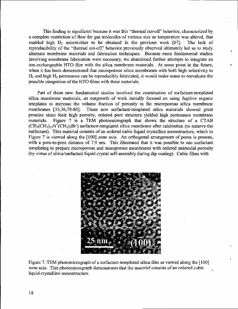
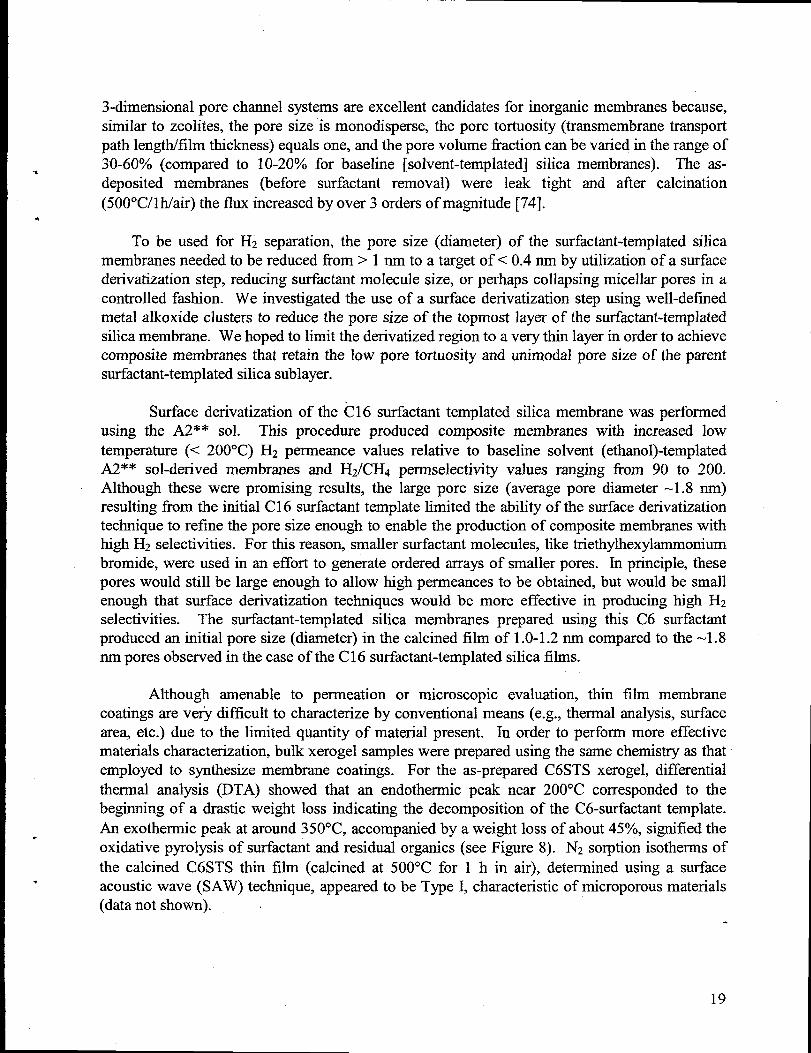
Part of these new fundamental studies involved the examination of surfactant-templatedsilica membrane materials, an outgrowth of work initially focused on using iigitive organictemplates to increase the volume fraction of porosity in the microporous silica membranemembranes [35,36,78-80]. These new surfactant-templated silica materials showed greatpromise since their high porosity, ordered pore structure yielded high permeance membranematerials. Figure 7 is a TEM photomicrograph that shows the structure of a CTAB(CHJ(CH2)15~(CH~)~Br-) surfactant-templatedsilica membrane after calcination (to remove thesurfactant). This material consists of an ordered cubic liquid crystallinemesostructure, which inFigure 7 is viewed along the [100] zone axis. An orthogonal arrangementof pores is present,with a pore-to-pore distance of 7.9 nm. This illustrated that it was possible to use surfactanttemplating to prepare microporous and mesoporous membranes with ordered unimodal porosity(by virtue of silica/surfactantliquid crystal self-assembly during dip coating). Cubic films with
.
.Figure 7. TEM photomicrograph of a surfactant-templatedsilica film as viewed along the [100]zone axis. This photomicrograph demonstratesthatthe material consists of an ordered cubic -liquid crystallinemesostructure-
18
3-dimensional pore channel systems are excellent candidates for inorganic membranes because,similar to zeolites, the pore size is monodisperse, the pore tortuosity (transmembranetransportpath length/film thickness) equals one, and the pore volume fraction can be varied in the range of30-60% (compared to 10-20V0 for baseline [solvent-templated] silica membranes). The as-deposited membranes (before surfactant removal) were leak tight and after calcination(500°C/lh/air) the flux increased by over 3 orders of magnitude [74].
To be used for H2 separation, the pore size (diameter) of the surfactant-templatedsilicamembranes needed to be reduced from >1 nm to a target of< 0.4 nm by utilization of a surfacederivatization step, reducing surfactantmolecule size, or perhaps collapsing micellar pores in acontrolled fashion. We investigated the use of a surface derivatization step using well-definedmetal alkoxide clusters to reduce the pore size of the topmost layer of the surfactant-templatedsilica membrane. We hoped to limit the derivatized region to a very thin layer in order to achievecomposite membranes that retain the low pore tortuosity and unimodal pore size of the parentsurfactant-templatedsilica sublayer.
Surface derivatization of the 616 surfactanttemplated silica membrane was performedusing the A2** sol. This procedure produced composite membranes with increased lowtemperature (< 200”C) H2 permeance values relative to baseline solvent (ethanol)-templatedA2** sol-derived membranes and Hz/Cm permselectivity values ranging fi-om 90 to 200.Although these were promising results, the large pore size (average pore diameter -1.8 nm)resulting from the initial C16 surfactanttemplate limited the ability of the surface derivatizationtechnique to refine the pore size enough to enable the production of composite membraneswithhi@ H2 selectivities. For this reason, smaller surfactantmolecules, like triethylhexylammoniurnbromide, were used in an effort to generate ordered arraysof smaller pores. In principle, thesepores would still be large enough to allow high permeances to be obtained, but would be smallenough that surface derivatization techniques would be more effective in producing high H2selectivities. The surfactant-templated silica membranes prepared using this C6 surfactantproduced an initial pore size (diameter) in the calcined film of 1.0-1.2 nm compared to the -1.8runpores observed in the case of the C 16 surfactant-templatedsilica films.
Although amenable to permeation or microscopic evaluation, thin film membranecoatings are verj difficult to characterize by conventional means (e.g., thermal analysis, surfacearea, etc.) due to the limited quantity of material present. In order to perform more effectivematerials characterization,bulk xerogel samples were prepared using the same chemistry as thatemployed to synthesize membrane coatings. For the as-prepared C6STS xerogel, differentialthermal analysis (DTA) showed that an endothermic peak near 200”C corresponded to thebeginning of a drastic weight loss indicating the decomposition of the C6-surfactanttemplate.An exothermic peak at around 350”C, accompanied by a weight loss of about 45Y0,signified theoxidative pyrolysis of surfactantand residual organics (see Figure 8). N2 sorption isotherms ofthe calcined C6STS thin film (calcined at 500”C for 1 h in air), determined using a surfaceacoustic wave (SAW) technique, appeared to be Type I, characteristicof microporous materials(datanot shown).
19
TGA/OTA FOR C6-SURFACTANT DERIVATRED SILICA
0 *W 200 Sw 400aw6ri07G
TEMPERATURE( “C)
800 w
Figure 8. Weight loss and heatevolution of C6STS xerogel duringthermalgravimetric analysis(TGA) and differential thermalanalysis(DTA) in air (1 atm) at a heatingrate of 2°C/min. Thedashed lines indicate the calcination temperaturesused to preparematerials for nitrogenadsorption and gas permeationmeasurements.
This new processing procedure (C6 surfactanttemplating + surface derivatization usingan A2** sol) resulted in both high flux and selectivity for the membranes with gradual changesof pore size (diameter) from 5.0 nm (commercial y–alumina support layer) to 1.0-1.2 nm(surfactant-templatedsilica sublayer), and then to 0.3-0.4 nrn (ultramicroporous silica top-layer)[81]. Electron micrographs which illustrate the cross-section and the surface of the supportedcomposite silica membrane are shown in FigureultrarnicroporousA2** layerwas around 30 nm.
9. The thickness of the defect-iiee
(a)
--+ Si02 (see (b)) on top
asymmetric~-Alz03
of y-A1203
support
Figure 9. Cross-sectional electron micrographs of a silica membrane preparedby C6 surfactanttemplating + surface denvatization: (a) SEM overview of the membrane, (b) TEM micrographreveals the detail of the separatesilica layers.
.
.
20
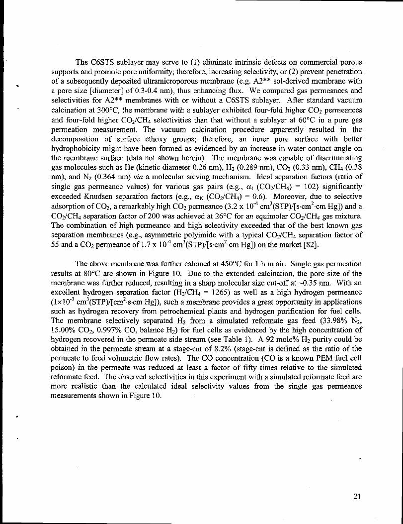
The C6STS sublayermay serve to (1) eliminate intrinsic defects on commercial poroussupports and promote pore uniformity, therefore, increasing selectivity, or (2) prevent penetrationof a subsequently deposited ultramicroporous membrane (e.g. A2** sol-derived membrane witha pore size [diameter] of 0.3-0.4 rim), thus enhancing flux. We compared gas permeances andselectivities for A2** membranes with or without a C6STS sublayer. After standard vacuumcalcination at 300”C, the membrane with a sublayer exhibited four-fold higher C02 permeancesand four-fold higher C02/C@ selectivities than that without a sublayer at 60°C in a pure gaspermeation measurement. The vacuum calcination procedure apparently”resulted in thedecomposition of surface ethoxy groups; therefore, an inner pore surface with betterhydrophobicity might have been formed as evidenced by an increase in water contact angle onthe membrane surface (data not shown herein). The membrane was capable of discriminatinggas molecules such as He (kinetic diameter 0.26 rim), H2 (0.289 nrn), C02 (0.33 rim), CH4 (0.38rim), and N2 (0.364 nrn) via a molecular sieving mechanism. Ideal separation factors (ratio ofsingle gas perrneance values) for various gas pairs (e.g., al (COZ/CH4) = 102) significantlyexceeded Knudsen separation factors (e.g., ~K (C02/Cfi) = 0.6). Moreover, due to selectiveadsorption of C02, a remarkablyhigh C02 permeance (3.2 x 104 cm3(STP)/[s.cm2.cm Hg]) and aC02/CH4 separation factor of 200 was achieved at 26°C for an equimolar C02/CH4 gas mixture.The combination of high permeance and high selectivity exceeded that of the best known gasseparationmembranes (e.g., asymmetric polyimide with a typical C02/CH4 separation factor of55 and a C02 perrneanceof 1.7 x 10⁻⁴cm3(STP)/[s.cm2-cm Hg]) on the market [82].
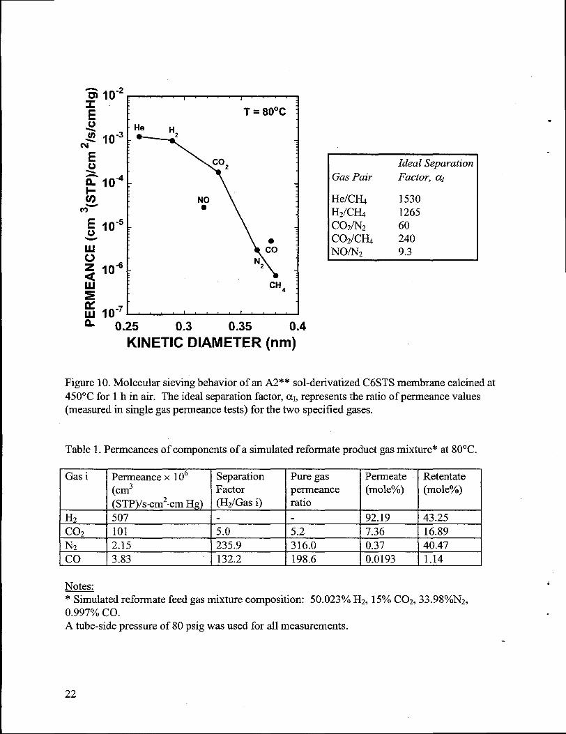
The above membranewas furthercalcined at 450”C for 1 h in air. Single gas permeationresults at 80”C are shown in Figure 10. Due to the extended calcination, the pore size of themembrane was tier reduced, resultingin a sharpmolecular size cut-off at -0.35 nm. With anexcellent hydrogen separation factor (H2/CH4 = 1265) as well as a high hydrogen perrneance(1x10⁻³ cm3(STP)/[cm2.s.cm Hg]), such a membrane provides a great opportunity in applicationssuch as hydrogen recovery from petrochemical plants and hydrogen purification for fuel cells.The membrane selectively separated H2 from a simulated reforrnate gas feed (33.98Y0 N2,15.00% C02, 0.997% CO, balance H2) for fiel cells as evidenced by the high concentration ofhydrogen recovered in the permeate side stream(see Table 1). A 92 mole% H2 purity could beobtained in the permeate stream at a stage-cut of 8.2’?40(stage-cut is defined as the ratio of thepermeate to feed volumetric flow rates). The CO concentration (CO is a known PEM fuel cellpoison) in the permeate was reduced at least a factor of fifty times relative to the simulatedreformate feed. The observed selectivities in this experiment with a simulatedreforrnatefeed aremore realistic than the calculated ideal selectivity values from the single gas permeancemeasurementsshown in Figure 10.
w
1“’ I 1 j
T = 80”C
-He H
N:
N2
CH~
1 1
Ideal Separation
Gas Pair Factor-, @
He/C?& 1530HZICHA 1265COJN2 60C02/CHo 240NO/N2 9.3
n 0.25 0.3 0.35 0.4
KINETIC DIAMETER (rim)
Figure 10. Molecular sieving behavior of an A2** sol-derivatized C6STS membrane calcined at450°C for 1 h in air. The ideal separahon factor, ~1,representsthe ratio of permeance values(measured in single gas permeance tests) for the two specified gases.
Table 1. Permeances of components of a simulatedreformate product gas mixture* at 80°C.
IGas i I Permeance x 106 I Separation I Pure gas IPermeate IRetentate(cm3 Factor permeance (mole%) (mole%)
(STP)/s-cm2-cm Hg) (H2/Gw i) ratio
H, 507 92.19 43.25I co, I 101 I 5.0 ! 5.2 I 7.36 t 16.89t N, ! 2.15 I 235.9 I 316.0 I 0.37 I 40.47[co I 3.83 I 132.2 I 198.6 ! 0.0193 I 1.14------ 1 ----
Notes.~ulated reformate feed gas mixture composition: 50.023°/0 H2, 15°/0C02, 33.98°/0N2,0.997’% co.A tube-side pressure of 80 psig was used for all measurements.
22
Summary
This study determined that it was possible to integrate ion-exchangeable HTO films intothe structure of composite microporous ceramic membranes and that the baseline (solvent-templated) silica membranes still exhibited molecular sieving behavioral high temperatures(>400”C). Unfortunately, it was also determined that the “thermal cut-off” behaviorobserved for both baseline silica and surface derivatized silica (titania/silica)reproducible. This finding resulted in a return to more fundamental studiesrnicroporous ceramic membrane fabrication.
previouslywas non-related to
The qualityof the support is crucial to the quality of overlying membranelayer. Pinholesand surface roughness on the support normally produce defects in the subsequently depositedlayer. We designed a new protocol to improve membrane performance and reproducibility.First,we deposited a surfactant-templatedmicroporous or mesoporous intermediatelayer on topof a commercial asymmetric alumina membrane support to both improve surface finish andprevent the subsequently deposited silica sol used for surface derivatizationfi-ompenetratingintothe support. Second, membranes were dip-coated under Class 100 clean room conditions toavoid dust contamination and were calcined to promote further pore shrinkage. This newprocedure resulted in both high flux and selectivity for the membranes with gradual changes ofpore size (diameter) fi-om 5.0 nrn (commercial y–alumina support layer) to 1.0-2.0 mn(surfactant-templatedsilica sublayer), and then to 0.3-0.4 nm (30 run thick, ukrarnicroporoussilica top-layer). The subject membranes are capable of molecular sieving and could find greatuse in applications such as purification of subquality naturalgas, reduction of green house gases(e.g. COZ) and hydrogen recove~ f?om processing gases and feedstocks.
Chapter IL Bulk Catalyst Development Efforts
Experimental
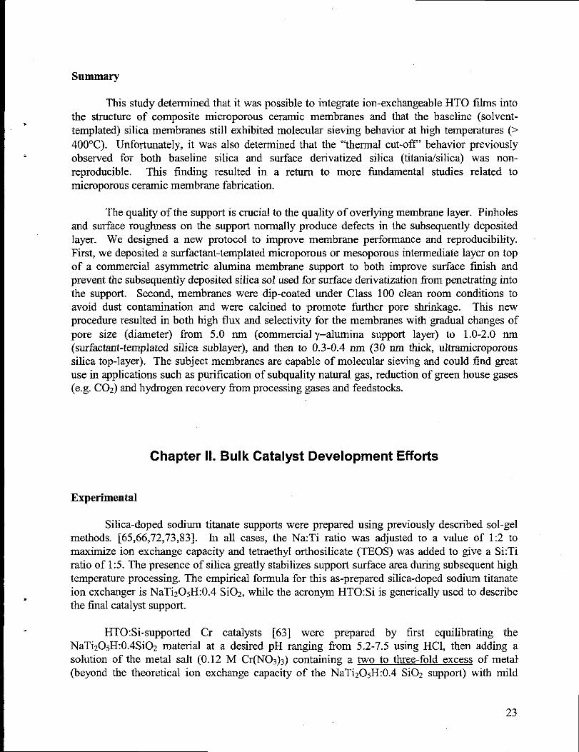
Silica-doped sodium titanate supports were prepared using previously described sol-gelmethods. [65,66,72,73,83]. In all cases, the Na:Ti ratio was adjusted to a value of 1:2 tomaximize ion exchange capacity and tetraethylorthosilicate (TEOS) was added to give a Si:Tiratio of 1:5. The presence of silica greatly stabilizes support surface areaduring subsequenthightemperatureprocessing. The empirical formula for this as-prepared silica-doped sodium titanateion exchanger is NaTi205H:0.4 Si02, while the acronym HTO:Si is generically used to describethe final catalystsupport.
HTO:Si-supported Cr catalysts [63] were prepared by first equilibrating theNaTiz05H:0.4Si02 material at a desired pH ranging from 5.2-7.5 using HC1, then adding asolution of the metal salt (O.12 M Cr(N03)3) containing a two to three-fold excess of metal(beyond the theoretical ion exchange capacity of the NaTiz05H:0.4 Si02 support) with mild
23
stirring. After one hour, the resulting Cr/HTO: Si was filtered, washed with water and acetone,and dried under house vacuum (3-5 in. Hg) at room temperature. Separate acidificationprocedures were not necessary to remove residual non-exchanged Na+ fi-om the catalystprecursors due to the combination of the large excess of Cr+3used in the ion exchange procedure,the long equilibration time allowed for cation exchange, and the relatively low pH used for ionexchange.
To prepare HTO:Si-supported Pt-based catalysts,a single large batch of a nominal 1 wt.YoPt/HTO:Si catalyst material (calcined basis) was prepared and subsequently doped with Sn andRe to prepare Pt-Sn/HTO:Si and Pt-Re/HTO:Si catalystmaterials. The initial 1 wt.YoPt/HTO:Sicatalystmaterialwas preparedusing standardtechniques [84]. Briefly, 0.96 g of Pt(NH&@JO&was dissolved in 750 ml of deionized water, and 80 g of NaTi205H:0.4 Si02 powder was addedto form a slurry. Following slurry formation, the pH was lowered to 5.5 using 10 wt.YoHN03and held there for 10 min by adding 10 wt.OAHN03 dropwise as needed. The slurry was thenfiltered using a coarse porosity glass fit Buchner fiumel and rinsed with DI water. Because thisPt loading represents only a small portion of the overall cation exchange capacity of theNaTi205H:0.4 Si02 material, the initial ion exchange product material contained a relativelylarge quantity of residual sodium (> 2 wt.Yo). Therefore, separate acidification was required toremove this residual sodium to produce a low sodium (< 0.5 Wt.O/ONa+ on a calcined basis)Pt/HTO:Si catalyst material. For acidification, the filter cake from the original ion exchangeprocedure was redispersed in 750 ml DI water to form a slurry and then additions of 10 wt.YoHN03 were used to lower the pH of the slurryto 3.9, where it was held for a period of 3 min.Following this treatment, the slurry was filtered and rinsed with deionized water as describedabove. The acidification procedure was repeateda total of three additional times. After the finalacidification and water rinse, the filter cake was rinsed three times with acetone and vacuumdried atroom temperature.
Catalyst precursor materials were analyzed for metal content by atomic absorptionspectrophotometry (AAS), volatiles contents were determined by weight loss measurements inconjunction wifi standard calcination treatments, and surface areas were measured by Nzadso~tion using the BET method (both before and after standardcalcination treatments). Theas-prepared catalyst precursor powders were granulatedto a size range of -60/+80 mesh. Thiswas accomplished by firstpressing a 1.125 in. dia pellet (-2 g) using a pressure of 12 kpsi. Lightgrinding with a mortar and pestle was then used to generate the desired mesh fraction. The Pt-based/HTO:Si catalyst granules were calcined at 600”C for 2 h (heating rate = 5°C/min up to550”C, then 1 OC/minfrom 550 to 600°C) in stagnantair.
Pt-Re/HTO:Si and Pt-Sn/HTO:Si catalysts(both containing 1:1 weight ratios of Pt:Re orSn) were prepared by doping the calcined Pt/HTO:Si granules with appropriate Re and Snprecursors, respectively. In the case of the Pt-Re/HTO:Si catalyst, 0.07 g of NH4Re04 wasdissolved in 4.4 ml deionized water, with the resulting solution carefidly added to 5.0 g ofcalcined Pt/HTO:Si granules. After overnight drying at room temperature in air, followed bydrying at 100”C in air for 2 h, the Pt-Re/HTO:Si catalystprecursors were calcined at 600”C for 2h in stagnant air as previously described. In the case of the Pt-Sn/HTO:Si catalyst, 5.0 g ofcalcined Pt/HTO:Si granuleswere impregnatedusing 4.4 ml of a solution of a 0.095 M Tin (IV)
24
.
.
●

2,6-bis-isopropylphenoxide (Sn[2,6-0CGHq(CH(CHq)z)2]4)in toluene. Subsequent drying andcalcination treatmentswere identical to those previously described for the Pt-Re/HTO:Si catalyst.
In the case of the Pt-based/HTO:Si catalysts, all granulated samples loaded into theT
reactor for testing were previously calcined at 600”C. In contrast, the Cr/HTO:Si catalystgranules were loaded into the reactor in the as-prepared form (without any heat treatmentabove
. room temperature) and heat treated in situ prior to catalyst testing. Consequently, significantcatalyst weight loss and shrinkageof the catalystbed volume in the flow reactor were observedfor the Cr/HTO:Si catalysts relative to the Pt-base&HTO:Si catalysts, which exhibited nosignificant shrinkage. In all cases, space velocity values are referenced to the final catalystbedvolumes or weights as appropriate.
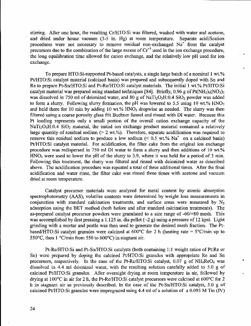
Activity measurements were made in a conventional atmospheric pressure packed bedflow reactor shown schematically in Figure 11 [63,85]. Gases were fed through calibratedmassflow controllers and up to two gases could be fed at any time (only one mass flow controller isshown in the figure for clarity). The system was capable of handling both gas and liquid feeds,with an HPLC pump used to control liquid feed rate. Only liquid feeds, eitherpure isooctane orpure n-heptane, were used in this study. The reactantsentered a high temperatureoven, and werepreheatedand mixed (if multiple feeds were used) in a 1/8 in. dia coiled stainless steel tube at thereactor inlet. The preheated reactants then entered a 3/8 in. dia stainless steel tube (wallthickness 0.065 in.) containing the packed catalyst bed. The catalyst was supported on a finesteel mesh located at the bottom of the reactor. Depending on catalystdensity, volatiles content,and estimated shrinkage, 2-4 g of granulated(-60/+80 mesh) catalyst were typically used to givea nominal final catalyst bed volume of 3.6 cc. Actual final catalyst bed volumes ranged horn3.1-4.1 cc. Reactant flow rateswere adjusted to provide weight hourly space velocity (WHSV)values of 0.6-3.0 g feed/(g catalyst-h),using the final weight of the catalyst sample (after testing)as a reference. This helped normalize differences in volatiles content among the varioussamples. The corresponding range of liquid hourly space velocity (LHSV) values was 0.8-3.8 ccfeed/cc catalyst-h). Reaction temperature ranges utilized for this study were 590-600”C forisooctane dehydrogenation experiments, and 525-575°C for. n-heptanedehydrogenation/dehydrocyclization. After exiting the reactor, product gases were exhaustedthrough the sample loop of a gas chromatography,where C1-C4 hydrocarbons were analyzedrelative to known standards using a flame ionization detector (FID). Since this gaschromatographywas not equipped with a TCD, no direct measurementsof H2production could bemade. Liquid samples were condensed by cooling with an ice bath, and the collected liquidswere analyzed by gas chromatography using an FID and mass spectrometry relative to knownstandards. Reactor temperaturewas measured by three thermocouples externally attachedto thetop, middle, and bottom of the reactor, and one thermocouple located inside the reactor at thebottom of the catalyst bed. No significant differences were ever observed among the four
.thermocouples indicating that the reactor operated in an isothermal mode. In addition to theCr/HTO:Si and Pt-based/HTO:Si catalysts, a commercial 7.5 w&4 Cr/y-A1203 catalyst (Girdler
. G-41, supplied by United Catalysts,Inc.) was also tested as a benchmark.
25
. I
I FEED
Figure 11. Schematic diagramof conventional packed bed dehydrogenationreactor.
A typical reaction sequence began with heating of the catalystbed to reaction temperaturein flowing nitrogen. Once temperaturewas reached, the nitrogen flow was stopped and reactantflow begun. Product streamsampling and analysis for both gas and condensed liquid species wastypically performed at 20 min intervals. For the Pt-based/HTO:Si catalysts,reduction treatmentsin pure hydrogen (at 500-550°C for 0.5-1 h) were used to activate the catalysts in situ prior todehydrogenation testing. For all catalysts, air oxidation at 550°C for times ranging horn 10 minto 2 h was used to regeneratethe catalysts at periodic intervals. After completion of a reactionsequence, the reactant flow was shut off and the reactor was cooled to room temperature inflowing nitrogen. After conclusion of a reactor test, the catalyst was removed from the reactorand saved for surface areaanalysis.
Results and Discussion
Preliminary Isooctane Dehydrogenation Screening Experiment
For this initial screening experiment, a 1.6 wt.% Fe/HTO:Si catalyst (EBL87, Fe loadingreported on an as-prepared basis) previously used for ethylbenzene dehydrogenation (to styrene)[63,64] was evaluated for hydrogen generation via isooctane dehydrogenation to olefin products.The most likely liquid isooctane (2,2,4-trimethylpentane) dehydrogenation products are 2,4,4-trimethyl-l-pentene and 2,4,4-trimethyl-2-pentene, with reaction to each of these productsgeneratingone mole of H2. At a reaction temperatureof 600°C and a WHSV of 0.5- 1.5 h-l, lessthan2% of the total isooctane fed to the reactor as liquid was converted to liquid dehydrogenated
26
.
products. However, significant conversion of isooctane to gaseous products was observed,indicating the presence of cracking reactions. These cracking reactions were undesirable sincethey produced non-selective products (C1-C5 alkanes and alkenes) which not only significantlyreduced the hydrogen yield, but ultimatelyrequired separation from the desired H2 product. Thevpresence of extensive branching in isooctane and the absence of multiple C-C single bonds thatcan be dehydrogenated not only resulted in a low ratio of dehydrogenation to cracking, but also
. limited the total amount of hydrogen thatcould be produced (even if cracking was eliminated).
Our results were a bit surprisingsince it has been reported thattrimethylpentanesreactedover chromia/alumina [86,87] form xylenes via skeletal rearrangement (isomerization) andaromatizationreactions. The active phase (iron oxide) and the HTO:Si support are significantlydifferent from a chromia/alumina catalyst and could possibly explain our observed results.Rather than ftier pursue the isooctane dehydrogenation strategy, we chose to focus ourattentionon the use of n-heptane dehydrogenation/dehydrocyclization as a model reaction.
Heptane Dehydrogenation/Dehydrocyclization Experiments
The dehydrogenation/dehydrocyclization of n-heptane is a more suitable choice as amodel reaction for catalysttesting for two reasons: 1) it yields a significant quantityof hydrogen;and 2) it has been well studied. The conversion of normal alkanes to aromatic compoundsrepresents an important class of catalytic reforming reactions, which are primarily used toproduce high research octane number (RON) branched or aromatic compounds to improve theantiknock properties of gasoline blends. This is dramatically illustratedby comparing the RONvalues for the C7 hydrocarbons n-heptane(0) and toluene (124) [68,69,86].
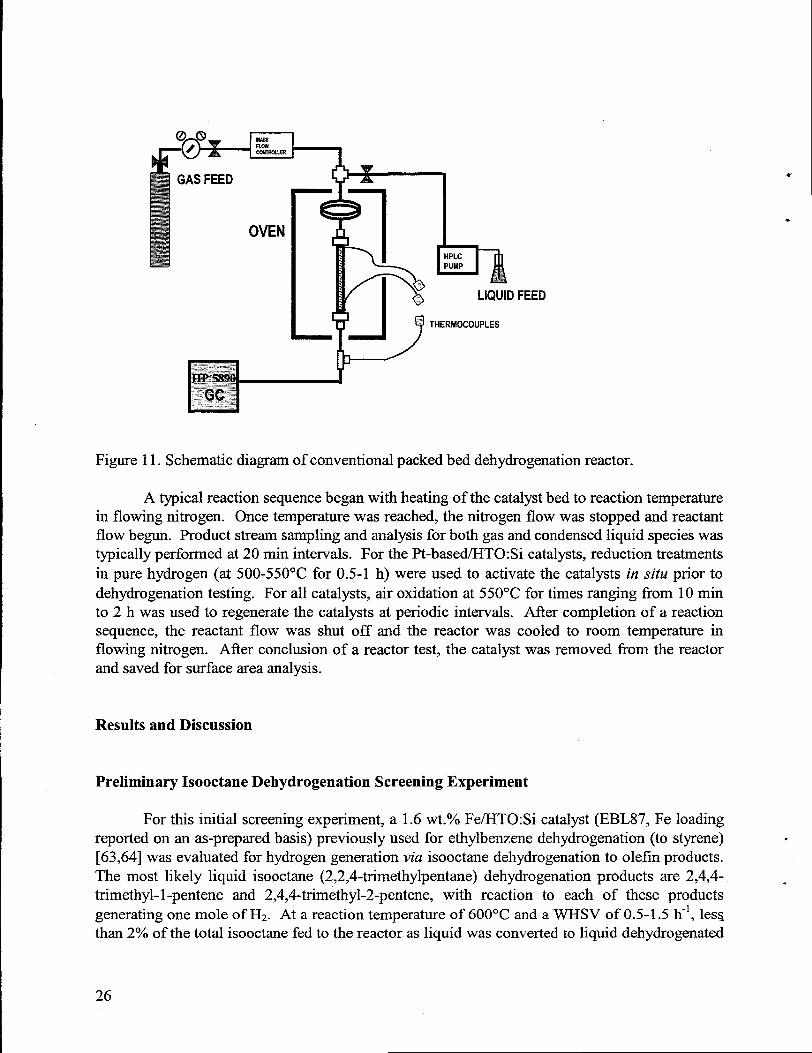
The net chemical reaction for dehydrogenatiorddehydrocyclization of n-heptane totoluene is illustratedbelow in Figure 12.
C7H16 C7H8
n-heptane toluene
Figure 12. Net chemical reaction for dehydrogenatiotidehydrocyclization of n-heptanetotoluene..
Several different types of reactions can occur in a dehydrocyclization scheme (e.g., the. formation of toluene from n-heptane); different catalytic sites can be involved, including metallic
active sites (e.g., Pt or Cr203) and acidic sites on the support. Under typical reforming conditions(high operating pressures including a significant partial pressure of H2), possible reaction pathscan include a metallic monofunctional path, a metallic bifhnctional path, and an acid bifunctional
27

path, depending on the specific catalystisupportcharacteristics and reaction conditions [69,88].The metallic monofunctional path involves a single metallic active site and a cyclohexanicintermediatewhich can be rapidly dehydrogenatedto form toluene, although several groups stillpostulate a mechanism involving paraffin dehydrogenation to diolefin or triolefin species beforecyclization [89]. For example, over chromia/alumina catalysts, Steiner [87] has shown thatdehydrogenation reactions are suppressed by H2,resultingin direct n-heptanecyclization to forma naphthene (six carbon member ring) intermediate (e.g., methylcyclohexane), consistent withthis metallic monofimctional route. The metallic bifunctional pathway involves both metallicand acid active sites, with cyclization of a 5 carbon ring intermediate (e.g., ethylcyclopentane ordimethylcyclopentanes) on the metallic site followed by gas phase migration to and ringexpansion on the acid site (carbonium ion mechanism), and a final dehydrogenation step on themetallic site. The acid bifunctional pathway is supposed to take place on acid sites via olefins ordiolefms produced from paraffin. Acid sites become increasingly important at higher reactiontemperatures(> 425”C) [90]. For all of these routes, cyclization is believed to be the probablerate determining step. In contrast, for the use of neat n-heptane feeds run over chromia/aluminacatalysts at or near atmospheric pressure (nontypical reforming conditions), it has been shownthat an initial slow catalytic dehydrogenation step to produce an olefin (e.g., 1-heptene) occurs,followed by a rapid cyclization step to produce toluene [86,87].
U
.
Catalysts based on alumina-supported metal oxides of the titanium, vanadium, andtungsten groups of the periodic table [86,87], as well as supported Pt-based catalysts [69,89-92],are well known to promote the dehydrogenation/dehydrocyclization reactions of normal alkanes[86,87]- A significant complicating factor affecting catalyst performance (activity, selectivity,and deactivation) is the fact that different types of metallic, metal oxide, and acid active siteshave the ability to catalyze a wide range of possible competing reactions, includinghydrogenolysis or cracking (cleavage), isomerization (cationic skeletal rearrangements), andhydrogenation. Aromatics are the most stable hydrocarbon species at temperaturesabove 250”C,and above 400”C equilibrium is displaced far enough toward aromatic products that evenconsiderable pressures of H2 do not significantly suppress dehydrogenation reactions [87].Typical reaction conditions involve temperaturesin the 450-550”C range and a wide range ofpressures [68]. No equilibrium limitations exist (at atmospheric pressure) for the n-heptanedehydrogenationldehydrocyclization reaction to toluene at 550”C. Partof the rationale for usingthis particular reaction temperature (550”C) was to compare thedehydrogenationldehydrocyclization results to previous propane dehydrogenationobtained at 550°C, for which equilibrium limitationsexist.
Supported Cr Catalysts
n-heptanetest data
.The active phase in supported Cr catalysts is generally acknowledged to be chromium
oxide (Cr203), which is also referred to as chromia. Although descriptors such as Cr/A1203,chromia/alumina, or Cr/HTO:Si will be used interchangeably in this report to denote therespective catalyst formulations, these different terms do not imply that distinct supported Cractive phases exist in each case. As stated above, it is expected thatCr203 is the active phase irlall of the supported Cr catalysts studied herein.
28
Commercial Benchmark Catalyst - Girdler G-41 Cr/A1203
1-.
This material was a 7.5 wt.% Cr/y-A1203 catalyst material (Girdler G-41, supplied byUnited Catalysts, Inc.) and was considered an effective benchmark representativeof commercialdehydrogenation catalysts. This Cr loading is equivalent to -11 wt.% Cr203. The primaryapplication of this catalyst is for hydrodeallcylation of toluene to benzene or substitutednaphthalenesto naphthalene[93].
Heptane dehydrogenatiotidehydrocyclization testing of this catalyst immediatelyfollowed propane dehydrogenation testingperformed in conjunction with a separateproject [85].Experience with other supported Cr catalysts has shown that initial propane dehydrogenationtesting does not significantly alter catalyst test results in subsequent heptanedehydrogenation/dehydrocyclization tests. For this catalyst,propane conversions to propylene at550”C were found to be equilibrium limited (25-30Y0 conversion), with a selectivity of 83-90’XO,illustratingthe effectiveness of this dehydrogenation catalyst. Theoretical calculations based onthermodynamic data indicate an equilibrium conversion of 30% at a temperatureof 540”C forpropane dehydrogenation to propylene [86,94].
Following propane dehydrogenation testing, the reactor was purged with N2 for 100 minat 550”C, while the HPLC pump was flushed and primed with the heptane liquid feed. Afterinitial heptane dehydrogenation/dehydrocycIization testing as a fiction of time-on-stream, theheptane flow was terminated, a N2 purge was performed, and an air regeneration step at 550°Cfor 1 h was performed. Heptane dehydrogenation/dehydrocyclization testingwas then continuedafter a subsequentN2 purge. Several sequentialregenerationcycles were petionned, followed byheptane dehydrogenatiorddehydrocyclization testing at alternatetemperatures(525 or 575”C) orweight hourly space velocities (WHSV, ranging from 2.0-3.0 g heptane/g catalyst.h).Unfortunately, no blank experiments without catalyst loaded in the tube or with the variouscatalyst support materials were performed to determine whether thermal reactions, reactionsoccurring on the reactor tube walls, or reactions occurring on the support (i.e., acid sites) wereimportant relative to the contribution of the active phase. However, based on previous propane[85] and isobutane [63] dehydrogenation experiments, the effect of the catalyst was expected todominate all other possible contributions.
Table 2 summarizes the n-heptane dehydrogenation/dehydrocyclization results obtainedwith the Girdler G-41 catalyst. This catalyst shows reasonable activity for heptane conversion totoluene thatis stable with a number of airregenerationcycles. One of the key parametersshown
. in Table 2 is the toluene selectivity, which indicates the mole 0/0of the original n-heptane feedconverted to toluene. This is the most desired liquid product since n-heptane conversion totoluene as described by Figure 12 yields significant amounts of H2. However, the data shown in
. Table 1 show that significant nonselective side reactions are occurring since only 35-50% of thetotal n-heptane fed to the reactor is converted to toluene. This could possibly be attributedtosignificant contributions of acid sites on the high purity y-A1203 support toward cationic skeletal-rearrangementsand cleavage reactions. This is consistent with the large amount of gaseous
29
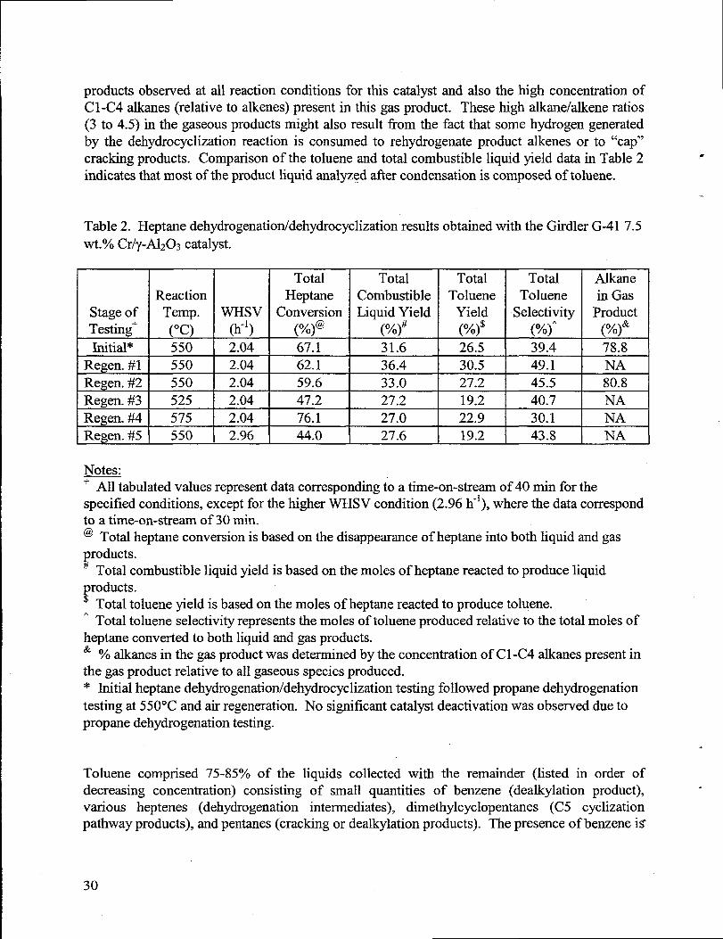
products observed at all reaction conditions for this catalyst and also the high concentration ofCl-C4alkmes (relative toalkenes) present inthis gas product. These high alkane/alkene ratios(3 to 4.5) in the gaseous products might also result from the fact that some hydrogen generatedby the dehydrocyclization reaction is consumed to rehydrogenate product alkenes orto “cap”cracking products. Comparison ofthetoluene and total combustible liquid yield data in Table2 *
indicates thatmost of the product liquid analyzed after condensation is composed of toluene.
Table 2. Heptane dehydrogenatiorddehydrocyclizationresultsobtained with the Girdler G-41 7.5wt.’%oCr/y-A1203catalyst.
LStage ofTesting+Initial*
ERegen. #1Regen. #2Regen. #3Regen. #4Regen. #5
-1-ReactionTemp. WHsv(“c) (h-’)550 2.04
=
550 2.04
550 2.04
525 2.04
575 2.04
550 2.96
TotalHeptane
Conversion(%)@67.162.159.647.2
76.144.0
TotalCombustibleLiquid Yield
(%)#31.6
36.4
33.0
27.2
27.0
27.6
LTotal Total
Toluene TolueneYield Selectivity(%)$ (%)’26.5 39.4
*
*
JAlkanein Gas
Product(%)&78.8
+
NA80.8
NANA I
-EL_JNotes.-+ All tabulatedvalues representdatacorresponding to a time-on-stream of 40 min for thespecified conditions, except for the higher WHSV condition (2.96 h-*),where the data correspondto a time-on-stream of 30 min.@ Total heptane conversion is based on the disappearanceof heptane into both liquid and gasproducts.# Total combustible liquid yield is based on the moles of heptanereacted to produce liquidproducts.$ Total toluene yield is based on the moles of heptanereacted to produce toluene.“ Total toluene selectivity representsthe moles of toluene produced relative to the total moles ofheptane converted to both liquid and gas products.& YOalkanes in the gas product was determinedby the concentration of C1-C4 alkanespresentinthe gas product relative to all gaseous species produced.* Initialheptane dehydrogenation/dehydrocyclization testing followed propane dehydrogenationtesting at 550”C and air regeneration. No significant catalyst deactivation was observed due topropane dehydrogenation testing.
Toluene comprised 75-85’% of the liquids collected with the remainder (listed in order ofdecreasing concentration) consisting of small quantities of benzene (dealkylation product), “various heptenes (dehydrogenation intermediates), dimethylcyclopentanes (C5 cyclizationpathway products), andpentanes(cracking or dealkylation products). The presence of benzene is
30
not a surprisesince the primary application of the Girdler G-41 catalyst is for hydrodeallcylationof toluene to produce benzene [93].
Steiner has extensively reviewed the literaturewith respect to aromatization reactions9over supported Cr catalysts [87]. Typical laboratory conditions for aromatization of neat n-heptane feeds at near atmospheric pressure involve temperaturesranging fi-om 450-550”C. At
.475”C, gas contact times of a few sec to -1 min yielded conversions of n-heptane to toluene of95’ZO,with < 5% of the feed converted to cracking products. Only unconverted n-heptane, 1-heptene, and toluene were observed in the condensed liquid effluent from the reactor [87,95].Higher temperatures are reported to lead to nonselective cracking reactions. Pines has alsopointed out the importance of using alkali metal additions to alumina supports to poison acidsites, decreasing the selectivity toward cracking reactions [86]. Our study utilized a high purity(non-alkali metal containing) y-AlzO~-supported Cr catalyst with short gas contact times (5-10see) at relatively high temperatures(525-575”C).on the Girdler G-41 alumina support and thesignificant nonselective cracking reactions andliteraturestudies.
The combination of the significant acid siteshigh temperatures utilized probably led todecreased performance relative to previous
The reaction temperaturehad significant effects on catalystperformance. Calculation ofthe apparent activation energy from the total heptane conversion data at 525-575°C yielded avalue of -13 kcal/mole. Although total heptane conversion increased significantly over thistemperaturerange, the production of toluene was optimized at 550”C, which validated theselection of this reaction temperature as the standard condition. Increasing the WHSV byincreasing the heptane flow rate to the reactor had a predictable effect on total heptaneconversion, even though the observed conversions were high with respect to typical differentialoperation conditions (< 10°/0conversion). Under differential operation conditions in a plug flowreactor, conversion should be inversely proportional to the reactant flow rate. Appropriatecalculations comparing the total heptane conversion observed for the final stage of testing at aWHSV of 2.96 h-l and 550°C (44.OYO)show excellent agreement with that predicted using thedifferential reactor operation assumption in conjunction with the overall average total heptaneconversion for the first three stages of testing (see Table 2) at a WHSV of 2.04 h“l and 550”C(43.8%).
Table 2 does not show data relative to catalyst deactivation as a fimction of time-on-streamat a given reaction temperature. Deactivation data for this catalyst will be presented inthe next section on Cr/HTO:Si catalysts so that the performance of the two types of catalystmaterials can be compared. With this overall test data as a baseline, a series of Cr/HTO:Sicatalysts were synthesized and evaluated with the goal of obtaining higher conversions andhydrogen generation ratesthanthe commercial Girdler G-41 7.5 wt.% Cr/y-Alz03 catalyst.
.Cr/HTO:Si Catalysts
Figure 13 shows the chromium loading versus pH forstudied. The Cr loading was found to increase in a quasi-linear
the four Cr/HTO:Si sample;fmhion with loading pH. Cr
31
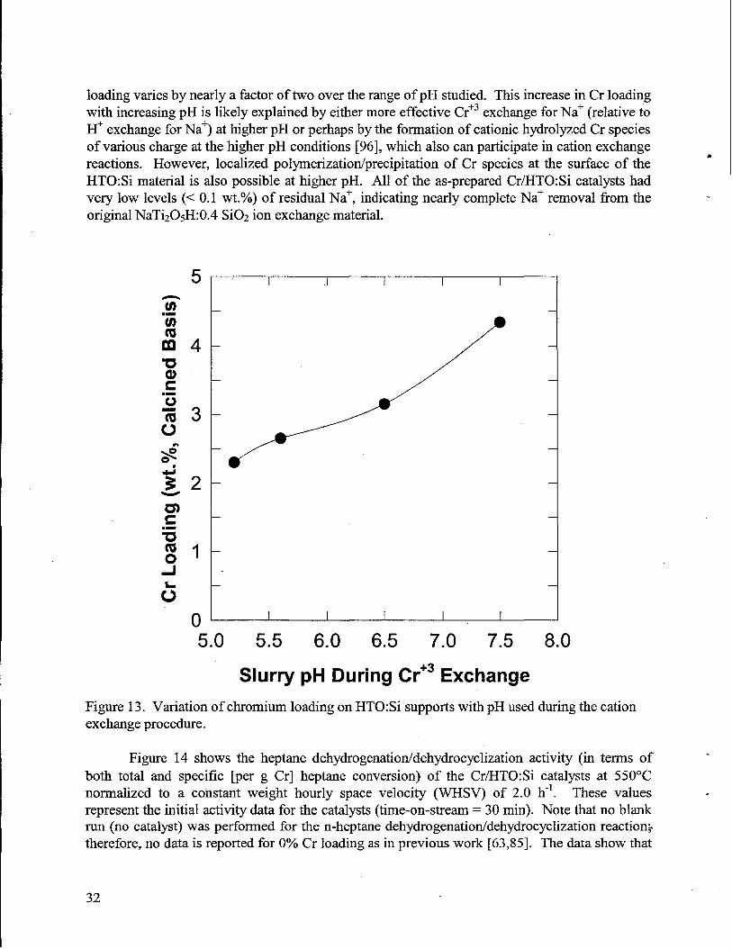
loading varies by nearly a factor of two over the range of pH studied. This increase in Cr loadingwith increasing pH is likely explained by eithermore effective Cr+3exchange for Na+(relative toH+ exchange for Na+) at higher pH or perhaps by the formation of cationic hydrolyzed Cr speciesof various charge at the higher pH conditions [96], which also can participatein cation exchangereactions. However, localized polymerizatiordprecipitation of Cr species at the surface of theHTO:Si material is also possible at higher pH. All of the as-prepared Cr/HTO:Si catalysts hadvery low levels (< 0.1 wt.O/O)of residual Na+, indicating nearly complete Na+ removal from theoriginal NaTi205H:0.4 SiOz ion exchange material.
5
1
0
I I 1 I
I I I I I
5.0 5.5 6.0 6.5 7.0 7.5 8.0
Slurry pH During Cr+3 Exchange
Figure 13. Variation of chromium loading on HTO:Si supports with pH used duringthe cationexchange procedure.
●
Figure 14 shows the heptane dehydrogenation/dehydrocyclization activity (in terms of “both total and specific [per g Cr] heptane conversion) of the Cr/HTO:Si catalysts at 550”Cnormalized to a constant weight hourly space velocity (WHSV) of 2.0 h-l. These values .representthe initial activity data for the catalysts (time-on-stream = 30 rein). Note thatno blankrun (no catalyst) was performed for the n-heptane dehydrogenatiorddehydrocyclization reaction>therefore, no data is reported for OOACr loading as in previous work [63,85]. The data show that
32
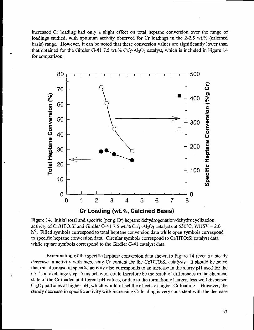
increased Cr loading had only a slight effect on total heptane conversion over the range ofloadings studied, with optimum activity observed for Cr loadings in the 2-2.5 wt.% (calcinedbasis) range. However, it can be noted that these conversion values are significantly lower thanthat obtained for the Girdler G-41 7.5 wt.Yo Cr/y-A1203catalyst,which is included in Figure 14.for comparison.
80 I I I I 1 I II
tI
II
1I
I ] 500
•1
- 400
- 300
- 200
1100
I
o~(-)01234567 8
Cr Loading (wt.%, Calcined Basis)
Figure 14. Initial total and specific (per g Cr) heptanedehydrogenation/dehydrocyclizationactivity of Cr/HTO:Si and Girdler G-41 7.5 wt.’XOCr/y-A1203catalystsat 550”C, WHSV = 2.0h-l. Filled symbols correspond to total heptane conversion datawhile open symbols correspondto specific heptane conversion data. Circular symbols correspond to Cr/HTO:Si catalystdatawhile square symbols correspond to the Girdler G-41 catalystdata.
Examination of the specific heptane conversion data shown in Figure 14 reveals a steady. decrease in activity with increasing Cr content for the Cr/HTO:Si catalysts. It should be noted
thatthis decrease in specific activity also corresponds to an increase in the slurrypH used for theCr+3ion exchange step. This behavior could thereforebe the resultof differences in the chemical.stateof the Cr loaded at different pH values, or due to the formation of larger, less well-dispersedCr203 particles at higher pH, which would offset the effects of higher Cr loading. However, thesteady decrease in specific activity with increasing Cr loading is very consistent with the decreas~
33
in dispersion of the active Cr phase expected with increased Cr loading. Transmission electronmicroscopy (TEM) or some other independent evaluation of Cr dispersion (e.g. magneticsusceptibility [87]) would be required to verify this speculation. Nevertheless, the fact thatoverall heptane conversion activity significantly decreases with increasing Cr loading makes itunlikely thatfhrtherimprovements could be achieved in the Cr/HTO:Si catalysts. Similar trendsin specific catalyst activity have previously been observed for Cr/HTO:Si catalysts used in bothpropane and isobutane dehydrogenation experiments, although overall catalyst activity wasinsensitive to Cr loading in these two previous cases [63,85].
Although not shown in Figure 14, it is worth noting that toluene selectivities were notsignificantly affected by increased Cr loading for the Cr/HTO:Si catalysts. Increased Cr loadingon the HTO:Si ion exchangers was effected by increasing the pH at which the HTO:Si wasequilibrated prior to Cr exchange. Therefore, increases in Cr loading could possibly have beenaccompanied by a decreased acidity of the catalyst and therefore a decrease in the fi-actionof thefeed streamconverted to gaseous products by cracking reactions. However, it is possible thattheeffect of the decreased Cr dispersions observed with increasing Cr loading (as evidenced by thesignificant decreases in specific activity with increasing Cr content shown in Figure 14)dominated any possible changes in support acidity for the Cr/HTO:Si catalysts with higher Crloadings.
These results are not consistent with the case of Fe/HTO:Si catalysts for ethylbenzenedehydrogenation [63,64], where a very sharp maximum in bulk activity with increasing ironloading was observed at a loading of -1.6 wt.% (as-prepared basis). This maximum wasattributedto the formation of a particular ion-exchanged iron species within a very narrow pHwindow. The slightly higher total heptane conversion observed in the 2-2.5 wt.% Cr loadingrange is fa less dramatic than that observed in the case of the Fe/HTO:Si catalysts used forethylbenzene dehydrogenation [63,64].
It is obvious fi-om the heptane conversion data described above that the Cr~TO:Si “catalysts compared poorly with the commercial Girdler G-41 7.5 Wt.O/O’ Cr/y-A1203 catalyst.Corresponding total toluene selectivities also compared unfavorably with the Girdler G-41catalyst; values of only 10-20% were achieved at these reaction conditions for all Cr/HTO:Sicatalysts. These overall toluene selectivities corresponded to -50Y0 selectivity to toluene in theliquid products, significantly lower than that observed for the Girdler G-41 catalyst (-75?40).Consistent with this fact, a large number of small peaks were observed via gas chromatographyof the liquid products; however, time was not taken to identi~ all of these individual speciessince the activity of the Cr/HTO:Si catalysts was low relative to the Girdler G-41 catalyst. TheCr/HTO:Si materials yielded gaseous alkane/alkene ratios of only 2 to 3, lower than thoseobserved for the commercial Girdler G-41 catalyst (see Table 2). This indicated that theseCr/HTO:Si catalysts may rehydrogenate a smaller fraction of the alkene products. Overall, thelow toluene and combustible liquid yields observed for the Cr/HTO:Si catalysts indicate a strongpresence of cationic skeletal rearrangement and cleavage (cracking) reactions, thereforedecreasing the selectivity of the catalysttoward aromatization. This might be due to the presenceof acid sites in the HTO:Si support resulting from Ti-O-Si bonding [66]. Since lower Cr.loadings were used for these catalysts this might lead to a lower fraction of the HTO:Si support
.
34
*
.
surface being covered with the active Cr phase, therefore allow greateracid site participation inthe non-selective (to aromatization)conversion of n-heptane.
Several possible explanations exist to explain the difference in activity and selectivity forthe Cr/HTO:Si catalysts relative to the commercial 7.5 wt.?40Cr/y-A1203(Girdler G-41) catalyst.In terms of catalyst activity on an overall or specific (per g Cr) basis, Figure 14 shows that theGirdler G-41 catalyst is significantly more active than the Cr/HTO:Si catalysts. This could bedue to the significant difference in chemistry between the high purity y-AlzO~ and HTO:Sisupports used for these catalysts. Following Na+ removal and heat treatment,the amorphousHTO:Si support crystallizes to form Ti02 phases (anatase, brookite, or rutile), although theaddition of the Si02 dopant helps preservehigh surface areaby retardingthe crystallizationof thelow temperature,high surface area Ti02 polymo~hs (anatase and brookite) to the low surfacearea, high temperature stable r@ile phase. Characterizationof the surface area of the variouscatalysts (by N2 adsorption using the BET method) revealed that after a 600°C calcinationtreatmentin air for 2 h, the surface areasof the Cr/HTO:Si catalysts ranged from 140-165 m2/g,compared to a value of 185 m2/g for the Girdler G-41 catalyst. If the x-axis of Figure 14 werereplotted to show Cr loading per m2 of catalystsurface area, the plot would look the same. Thus,one cannot explain the superior activity of the Girdler G-41 catalyst solely on a support surfaceareabasis. Another possibIe explanation might be related to a superior ability of the high purityy-A1203relative to Ti02 to disperse Cr/Cr203 phases. Also, the acidity of these different supportsmay play an important role in both the activity and selectivity of these different catalysts. Adetailed discussion of the possible differences in support acidity between the high purityy-A1203and HTO:Si supports has been given elsewhere [66]. Significant furtherwork would be requiredto identi~ the fimdamental differences between these two catalysts responsible for the observeddifferences in catalyst activity and selectivity.
The commercial 7.5 wt.VOCr/y-A1203 catalyst and the Cr/HTO:Si catalysts were alsocompared in the area of catalyst deactivation with increasing time-on-stream. It is wellestablished that commercial catalysts deactivate under typical industrial reaction conditions,requiringperiodic air regenerationtreatmentsto restore catalyst activity. It would be an obviousbenefit to develop more deactivation-resistantcatalysts for industrialchemical production. Cr/y-A1203 catalyst deactivation data reported by Steiner showed that the concentration of toluene inthe product decreases by a factor of 4x over a time-on-stream period of 2 h. It was also reportedthat the rate of catalyst deactivation could be significantly reduced by including a substantialpartialpressure of H2 in the feed. Under industrialreformer conditions, high-pressure operation(including a significant partialpressureof H2) with recycle of a portion of theproduct is typicallyutilized.
Figure 15 shows total heptane conversion data as a function of time-on-stream at areaction temperatureof 550°C and a nominal WHSV of 2 h-l. The performance of the 2.65 wt.O/OCr/HTO:Si catalyst was selected as representativeof all of the Cr/HTO:Si catalysts. The initialcatalystdeactivation and catalystpetiormance afterone air regenerationtreatmentat 550°C in airare shown in Figure 15. Furthercycling of the catalyst under similar conditions revealed verysimilar results. The large activity differenceCr/HTO:Si catalysts previously shown in Figure
between the Girdler G-41 and the 2.65 wt.OA14 are also illustratedin this figure. The Girdler
35
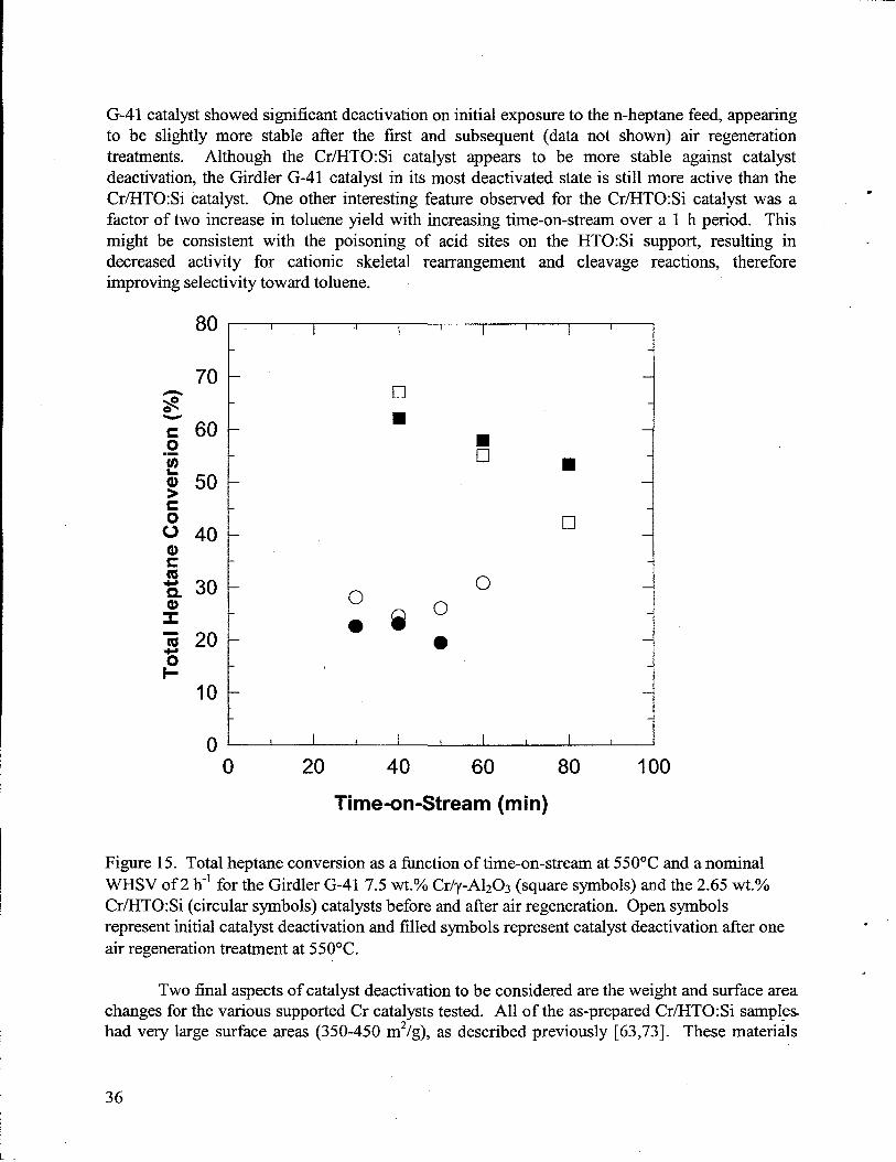
*
.improving selectivityy toward toluene.
801. I I h I I I I I I
70 -
60 -
50 -
40 -
30 “
7 2031-
❑
■
■•1
00Q
0●
● 10 20 40 60 80 100
Time-on-Stream (rein)
Figure 15. Total heptane conversion as a function of time-on-stream at 550”C and a nominalWHSV of 2 h-*for the Girdler G-41 7.5 wt.~. Cr/y-A1203(square symbols) and the 2.65 wt.YoCr/HTO:Si (circular symbols) catalystsbefore and after air regeneration. Open symbolsrepresentinitialcatalystdeactivation and filled symbols representcatalystdeactivation after oneair regenerationtreatmentat 550”C.
. I
. I
Two final aspects of catalystdeactivation to be considered are the weight and surface areachanges for the various supported Cr catalyststested. All of the as-preparedCr/HTO:Si sampleshad very large surface areas (350-450 m2/g), as described previously [63,73]. These materials
36
I
.
n
undergo significant surface areareduction (to 140-165 m2/g) and volatiles removal (22-28 wt.’XO)during a standardcalcination procedure (600°C/2h/air). Calcination of the Girdler catalystundersimilar conditions showed -10 wt.O/Oloss (probably due to adsorbed moisture) and a negligiblechange in surface area. By combining the volatiles content and surface area data for theCr/HTO:Si catalysts, it was possible to estimate the weight and surface area after reaction forthese materials, assuming no changes due to coking/catalyst deactivation. For all of theCr/HTO:Si catalysts, the observed weight loss ranged from 17-21 wt.%, significantly lower thanthe expected volatiles contents for these materials. This indicated that the Cr/HTO:Si catalystsexperienced a net wet gain due to coking on the order of -3-9%. Concurrent with this cokingwas a significant reduction in surface are% surface areas of the Cr/HTO:Si samples removedfrom the reactor ranged fi-om 100-120 m2/g, -25’%0below the values for the calcined samples.This decrease is also consistent with coking of the catalyst, which easily fills the smaller poresresponsible for the high surface area of these materials. A low temperature (100-150°C) wasused to outgas these samples prior to surface areameasurementsto ensure thatthe carbonaceousdeposits were not significantly volatilized. For comparison, the Girdler G-41 catalyst also wasobserved to lose less weight thanexpected after exposure to reaction conditions, indicating a netwet gain due to coking on the order of -5°/0. The percentage of surface area reduction for thismaterialrelative to its calcined only form was nearlyidentical to thatof the Cr/HTO:Si materials.
Thus, the most important finding from this section is that the commercial Girdler G-417.5 wt.YoCr/y-A1203catalystis clearly more active thanthe Cr/HTO:Si catalysts. The inabilitytoincrease the activity of the Cr/HTO:Si catalysts through increased metal loading leads to theconclusion that Cr/HTO:Si catalysts are unlikely to provide any benefit over currentlyavailabletechnology.
Pt-Based/HTO:Si Catalysts
A wealth of literatureexists with respect to Pt-based reforming catalysts [68,69,86,89-92]. Industrial catalysts have acidic functionality designed into the catalyst support. It isbelieved that dehydrogenatiodhydrogenation reactions are largely structure-insensitive (nosignificant particle size, shape, or surface structure/irregularitieseffect on activity or selectivity)and can proceed even on the smallest ensembles of active sites, possibly even-single Pt atoms[86,90]. If aromatization is viewed as consecutive dehydrogenation, similar behavior might beexpected. Consistent with this argument is the fact that these reactions are least affected bycarbonaceous deposits, sulfurpoisoning, or alloying of Pt with inactive components [90].
However, the overall scheme of possible competing reactions within a catalytic reformer,including hydrogenolysis, isomenzation, hydrogenatiorddehydrogenation, C5 cyclization, andaromatization, is complicated not only by the large variety of possible reactions but also by thefact that some of these reactions are structure-sensitive (particle size, shape, or surfacestructure/inegularities significantly affects activity or selectivity, e.g., hydrogenolysis), whileothers are structure-insensitive(e.g., dehydrogenation) [97-99]. Also, activity for these variedreactions is highly dependent on the specific reforming conditions (temperature,pressure, H2concentration, presence of poisons, etc.) as well as other characteristics of the catalyst (choice of
37
metal and support acidity). These complications make it extremely difficult to draw generalconclusions regarding optimum catalyst characteristics with respect to the overalldehydrocyclization/dehydrogenation scheme. Several authorshave observed a possible increasein catalyst deactivation due to carbon deposition (also referredto as self poisoning) with large Ptparticles, but interpretationof these results has been difficult due to many of the complicationsdescribed above [90].
The initial n-heptane dehydrogenation/dehydrocyclization data for the Pt-based catalystsafter a H2reduction treatmentat 500-550”C for 0.5-1 h is shown in Table 3. In one case, denotedas Pt/HTO:Si*, heptane dehydrogenatiorddehydrocyclization activity evaluation at 550°Cfollowed propane dehydrogenation activity testing at 550”C. This was done to clearly tie thecurrent Pt/HTO:Si catalyst development efforts with earlier propane dehydrogenation studiesinvolving inverse micelle/sol-gel formulated Pt/Si02 and Pt/A1203catalysts [85]. All Pt catalystsused herein had a nominal Pt loading of 1.0 Wt. O/O (calcined basis), with the Pt-Re/HTO:Si andPt-Sn/HTO:Si catalysts having a 1:1 weight ratio of Pt:Re (atomic ratio -1:1 Re:Pt) or Pt:Sn(atomic ratio -1.6:1 Sn:Pt). The reactor conditions were chosen so as to compare the heptanedehydrogenation/dehydrocyclization activity and selectivity data of the Pt-based/HTO:Sicatalysts with that observed for the Cr/HTO:Si and 7.5 Wt.O/OCr/y-A1203catalysts also evaluatedas part of this study.
Initial evaluation of the 1.0 wt.Yo Pt/HTO:Si catalyst for propane dehydrogenation at550°C showed that 20-30% conversion of propane and high selectivity to propylene (9O-1OOYO)were obtained. Equilibrium limited conversion was observed for this catalystat nominal WHSVvalues of 2-4 h-l (corresponding gas hourly space velocity [GHSV] values were nominally 3-6 ccfeed/(cc catalyst.h)), consistent with the results obtained for the 7.5 wt.YoCr/y-A120~(Girdler G-41) catalyst. This propane dehydrogenation result representsa significant improvement over theinverse micelle/sol-gel formulated Pt/Si02 and PtlA1203 catalysts investigated in a previousstudy, although these lattercatalysts contained lower Pt contents (nominal loading 0.3 Wt.O/Oon acalcined basis) and were testedat relatively high WSHV values (> 4 h-l) [85].
The first observation that can be made regarding the data in Table 3 is that the totalheptane conversions obtained for the Pt-based/HTO:Si catalysts are significantly lower thanthose obtained for the Girdler G-41 catalyst (see Table 2) and slightly lower than those obtainedfor the CrlHTO:Si catalysts (see Figure 14) run under nearly identical conditions. As expected,on a specific activity basis (per atom Cr or Pt), the Pt-basedlHTO:Si catalysts are more activethan the Girdler G-41 catalyst. However, bulk catalyst activity on an overall weight or volumebasis is the critical factor used to screen catalysts for industrial applications. Alkaneconcentrations in the gas product ranged horn 60-70°/0, similar to the values observed for theCr/HTO:Si catalysts. Overall, it may not be fair to compare the performance of Pt and Crcatalysts at the same operating conditions since considerable previous work has shown thatdifferent operating conditions (temperature,etc.) are required for optimum results with each typeof catalyst [86].
The major difference in reforming conditions required for Pt-based catalysts relative to(1-- or Me-based catalysts is the use of high operating pressures (10-30 atm total, including a
38
.
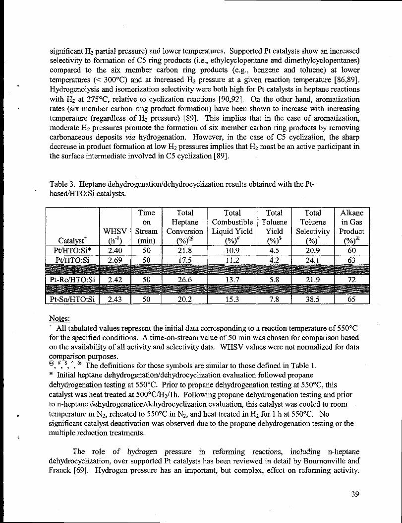
.
significantH2partialpressure) and lower temperatures. Supported Pt catalystsshow an increasedselectivity to formation of C5 ring products (i.e., ethylcyclopentane and dimethylcyclopentanes)compared to the six member carbon ring products (e.g., benzene and toluene) at lowertemperatures(< 300°C) and at increased H2 pressure at a given reaction temperature [86,89].Hydrogenolysis and isomerization selectivity were both high for Pt catalystsin heptanereactionswith Hz at 275°C, relative to cyclization reactions [90,92]. On the other hand, aromatizationrates (six member carbon ring product formation) have been shown to increase with increasingtemperature(regardless of H2 pressure) [89]. This implies that in the case of aromatization,moderate H2 pressures promote the formation of six member carbon ring products by removingcarbonaceous deposits via hydrogenation. However, in the case of C5 cyclization, the sharpdecrease in product formation at low H2pressuresimplies thatH2must bean active participantinthe surfaceintermediateinvolved in C5 cyclization [89].
Table 3. Heptanedehydrogenation/dehydrocyclization resultsobtained with the Pt-basedlHTO:Si catalysts.
Time Total Total Total Total Alkaneon Heptane Combustible Toluene Toluene in Gas
WHsv Stream Conversion Liquid Yield Yield Selectivity ProductCatalyst+ (h-’) (rein) (%)@ (%)# (%)$ (%)’ (’??)&
Pt/HTO:Si* 2.40 50 21.8 10.9 4.5 20.9 60
Pt./HTO:Si 2.69 50 17.5 11.2 4.2 24.1 63
Pt-Re/HTO:Si I 2.42 I 50 26.6 13.7 5.8 21.9 72
Pt-Sn/HTO:Si I 2.43 ! 50 I 20.2 I 15.3 I 7.8 38.5 I 65
Notes--+ All tabulatedvalues representthe initial datacorresponding to a reactiontemperatureof 550°Cfor the specified conditions. A time-on-stream value of 50 min was chosen for comparison basedon the availability of all activity and selectivity data. WHSV values were not normalized for datacomparison purposes.‘,’,’,’, & The definitions for these symbols are similar to those defined in Table 1.* Initialheptanedehydrogenation/dehydrocyclization evaluation followed propanedehydrogenationtesting at 550”C. Prior to propane dehydrogenation testingat 550°C, thiscatalystwas heat treatedat 500°C/H2/l h. Following propane dehydrogenationtestingand priorto n-heptanedehydrogenation/dehydrocyclization evaluation, this catalystwas cooled to room
E temperaturein N2, reheated to 550°C in N2, and heat treatedin H2for 1 hat 550”C. Nosignificant catalystdeactivation was observed due to the propane dehydrogenationtesting or themultiple reduction treatments.‘
The role of hydrogen pressure in reforming reactions, including n-heptanedehydrocyclization, over supported Pt catalystshas been reviewed in detail by Bournonville andFranck [69]. Hydrogen pressure has an important, but complex, effect on reforming activity.
39
When the H2pressure decreases at constanthydrocarbon pressure, the rate of dehydrocyclizationincreases up to a maximum and then tends toward zero for low H2 pressures. This providesevidence thata competition exists between H2 and hydrocarbons for the active sites on the metalparticles, which is fi.u-therexplained by the following two points: (1) at low pressures,H2 acts bylimiting the concentration of highly dehydrogenated species on the catalyst surface, which areknown coke precursors; and (2) at high pressures, through adsorption, H2 reduces the number ofvacant sites that are available for cyclization as well as the concentration of dehydrogenatedintermediatesnecessary for cyclization. It is importantto point out thatthis effect is independentof catalystageing.
The reactor conditions used herein are more representative of optimum conditions usedfor n-heptane dehydrogenation/dehydrocyclization over supported Cr catalyst materials. Ingeneral, lower temperatures (< 400°C) are more optimum for supported Pt catalysts [86].Equally unfortunate was the fact that no commercial Pt catalyst benchmark was run underidentical conditions to compare with the activity of the Pt-based/HTO:Si catalysts. Because ofthe high temperature used for n-heptane dehydrogenatiorddehydrocyclization (550”C), theselectivity to aromatization for these Pt-based catalysts has likely been significantly loweredrelative to other competing reactions (hydrogenolysis, isomerization, C5 ring closure, etc.).Total combustible liquid yield, toluene yield, and toluene selectivity values are all low for thesecatalysts relative to the data shown previously for the Girdler G-41 catalyst in Table 2, althoughcomparable to those obtained for the Cr/HTO:Si catalysts. However, since our experiments wereperformed with no Hz in the feed, low catalystactivity coupled with significant and rapid catalystdeactivation was not surprisingin the case of thePt-based catalysts.
Since supported Pt catalysts are difficult to synthesize in highly dispersed forms whichare stable athigh temperature,anotheralternativeis to disperse the Pt atoms within a given metalparticle composed of an alloy between Pt and a second metal. Various explanations for thepositive effect of alloying on catalyst performance have been postulated, including altering thesize of Pt atom surface ensembles and electronic modification of the catalytic properties of Pt[90-92,100-1 02]. By forming Pt alloys, it is possible to achieve a large and controlled portion ofisolated Pt atoms via dilution achieved in alloying techniques. Both Re and Ir are widely knownas effective alloying additives to improve catalyst selectivity and deactivation resistance of Ptreforming catalysts [90,91 ]. A common industrialreforming catalyst composition consists of aPt concentration ranging from 0.2 to 0.6 wt.’Yo,promoted/alloyed with a few hundred to a fewthousandppm of various additives, such as Re, Ir, Sn, or Ge, all supported on a high surface areaalumina support, whose acidity has been enhanced via chloride additions [69, 103]. Of this rangeof compositions, active phases consisting of 0.3 wt.O/OPt + 0.3 Wt.O/ORe appear to be fairlypopular [88,104,105]. Recently, Sn, although being an inactive single component catalyst, hasbeen identified as an effective alloying additive for isobutane dehydrogenation catalysts [100-102].
Boumonville and Franck discussed the effect of alloying of Pt with a second metal on n-heptane dehydrocyclization at 470°C over a range H2pressures [69]. Alloying of Pt with a widerange of metals (Ir, Re, Sn, Ge, Pb, or Rh [M:Pt atomic ratio=l :3]) was found to affect catalys$activity relative to pure Pt catalystsand to shift the activity maximum to lower H2pressures (e.g.,
40
.
.
.
Hz:n-C7Hlc-l-2). The Pt-Ir catalyst showed the highest activity, although the Pt-Rh and Pt-Recatalysts also exceeded the activity of the baseline 0.6 Wt.O/OPt catalyst at all H2 pressures. Itshould be noted that, in general, the activity of the Pt-Re catalyst only marginally exceeded theactivity of the Pt catalyst, except at low H2pressure(Hz:n-C7Hlc -l), where larger differences in.activity were observed. Interestingly,the Pt-Sn catalystexceeded the activity of the baseline 0.6wt.’%oPt catalyst only at low H2 pressure (Hz:n-CvH1c- 1), not performing as well at higher 1-12pressures. For n-heptane dehydrocyclization at 495°C and 14.6 atm (5: 1 Hz:n-CvH1c),Carter, et.al [105] showed thatPt-Re (+ 0.9 wt.O/OC1-)/A1203catalysts (1:1 Re:Pt, 0.3 Wt.O/OPt + 0.3 Wt.O/ORe) outperformed 0.3 wt.YoPt (+ 0.9 wt.YoC1-)/A1203catalystsover a 40 h time-on-streamperiodwith 0.5 ppm sulfir in the feed.
The comparison of the results of the different Pt-based/HTO:Si catalysts proved to bequite interesting. Although the Sn additive appearedto produce no improvement in total heptaneconversion relative to the Pt/HTO:Si catalyst, combustible liquid and toluene yields, as well astoluene selectivity, improved by almost 50?40relative to the values observed for the Pt/HTO:Sicatalyst (see Table 3). In this regard, the Pt-SnlHTO:Si catalyst also proved to be superior to thePt-Re/HTO:Si catalyst. Liquid product analysis by gas chromatography showed thatchromatograms representingthe liquid products from the Pt/HTO:Si and Pt-Re/HTO:Si catalystswere significantly more complex (with respect to the large number of small peaks observed)relative to the results obtained for the Pt-Sn/HTO:Si catalyst. Time was not takento identi~ allof the product liquid species since the activity of all of the Pt-based catalystswas low relative tothe Girdler G-41 catalyst. However, these qualitative results are consistent with the increasedtoluene selectivity of the Pt-Sn/HTO:Si catalyst relative to the other Pt-based catalysts. Onespecies in the liquid product that was quantified was pentanes. The Pt-Sn/HTO:Si catalystproduced a negligible amount of pentanes in the liquid products relative to the other Pt-basedcatalysts, indicating a higher selectivity toward dehydrocyclization (relative to hydrogenolysis).The higher activity for the Pt-Sn (-0.6:1 Sn:Pt atomic ratio)/HTO:Si catalyst is consistent withthe better performance of Pt-Sn catalyst (1:3 Sn:Pt) at low H2 pressure as described above [69].Note thatour experiments represented an extremely low H2 pressure (H2/n-heptanefmd ratio =O). The better performance of the Pt-Sn/HTO:Si catalyst might also be attributedto improvedresistance to deactivation [90,91,100-102].
For heptane dehydrocyclization at milder reaction conditions (400”C, 1 atrnH2, pulsereactor), Toumayan, et al. [106] showed thatincreasesin the Re content to an alumina-supportedPt catalyst (2V0total Pt + Re) resulted in a steadydecrease in specific catalystactivity (expressedas turnover frequency); selectivity changes involving decreased C5 ring closure/cyclization andincreased hydrogenolysis activity were also noted with increasing Re content. On a mildly acidicalumina support, Garland, Baiker, and Wokaun found an optimum range of Re:Pt atomic ratiobetween 1:1 and 1:3 (0.5 wt.% total metal concentration) that enhanced both the selective
*dehydrocyclization of n-heptane to toluene and the selective dehydrogenation ofmethylcyclohexane to toluene [107]. This is consistent with a wealth of literaturedata whichshows the high hydrogenolysis activity of supportedRe catalysts, and increases in hydrogenolysisactivity due to Re additions to supported Pt catalysts[90,108,109].
41
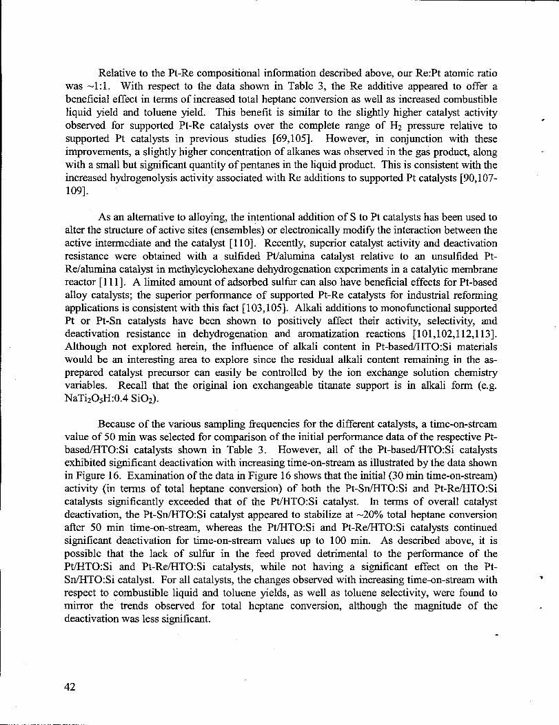
Relative to the Pt-Re compositional information described above, our Re:Pt atomic ratiowas -1:1. With respect to the data shown in Table 3, the Re additive appeared to offer abeneficial effect in terms of increased total heptane conversion as well as increased combustibleliquid yield and toluene yield. This benefit is similar to the slightly higher catalyst activityobserved for supported Pt-Re catalysts over the complete range of H2 pressure relative tosupported Pt catalysts in previous studies [69,105]. However, in conjunction with theseimprovements, a slightly higher concentration of alkaneswas observed in the g~ product, alongwith a small but significant quantityof pentanes in the liquid product. This is consistent with theincreased hydrogenolysis activity associated with Re additions to supported Pt catalysts [90,107-109].
As an alternativeto alloying, the intentional addition of S to Pt catalystshas been used toalterthe structureof active sites (ensembles) or electronically modifi the interactionbetween theactive intermediate and the catalyst [11O]. Recently, superior catalyst activity and deactivationresistance were obtained with a sulfided Pt/alumina catalyst relative to an unsulfided Pt-Re/alumina catalyst in methylcyclohexane dehydrogenation experiments in a catalytic membranereactor [111]. A limited amount of adsorbed sulfiu can also have beneficial effects for Pt-basedalloy catalysts; the superior pefiormance of supported Pt-Re catalysts for industrial reformingapplications is consistent with this fact [103,105]. Alkali additions to monofunctional supportedPt or Pt-Sn catalysts have been shown to positively affect their activity, selectivity, anddeactivation resistance in dehydrogenation and aromatization reactions [101,102,1 12,113].Although not explored herein, the influence of alkali content in Pt-based/HTO:Si materialswould be an interesting area to explore since the residual alkali content remaining in the as-prepared catalyst precursor can easily be controlled by the ion exchange solution chemistryvariables. RecaIl that the original ion exchangeable titanate support is in alkali form (e.g.NaTi205H:0.4 Si02).
Because of the various sampling frequencies for the different catalysts, a time-on-streamvalue of 50 min was selected for comparison of the initial performance data of the respective Pt-based/HTO:Si catalysts shown in Table 3. However, all of the Pt-based/HTO:Si catalystsexhibited significant deactivation with increasing time-on-stream as illustratedby the data shownin Figure 16. Examination of the data in Figure 16 shows thatthe initial (30 min time-on-stream)activity (in terms of total heptane conversion) of both the Pt-SnlHTO:Si and Pt-Re/HTO:Sicatalysts significantly exceeded that of the Pt/HTO:Si catalyst. In terms of overall catalystdeactivation, the Pt-Sn/HTO:Si catalyst appeared to stabilize at -20’?40total heptane conversionafter 50 min time-on-stream, whereas the Pt/HTO:Si and Pt-Re/HTO:Si catalysts continuedsignificant deactivation for time-on-stream values up to 100 min. As described above, it ispossible that the lack of sulfur in the feed proved detrimental to the performance of thePt/HTO:Si and Pt-Re/HTO:Si catalysts, while not having a significant effect on the Pt-Sn/HTO:Si catalyst. For all catalysts, the changes observed with increasing time-on-stream withrespect to combustible liquid and toluene yields, as well as toluene selectivity, were found tomirror the trends observed for total heptane conversion, although the magnitude of thedeactivation was less significant.
●
42
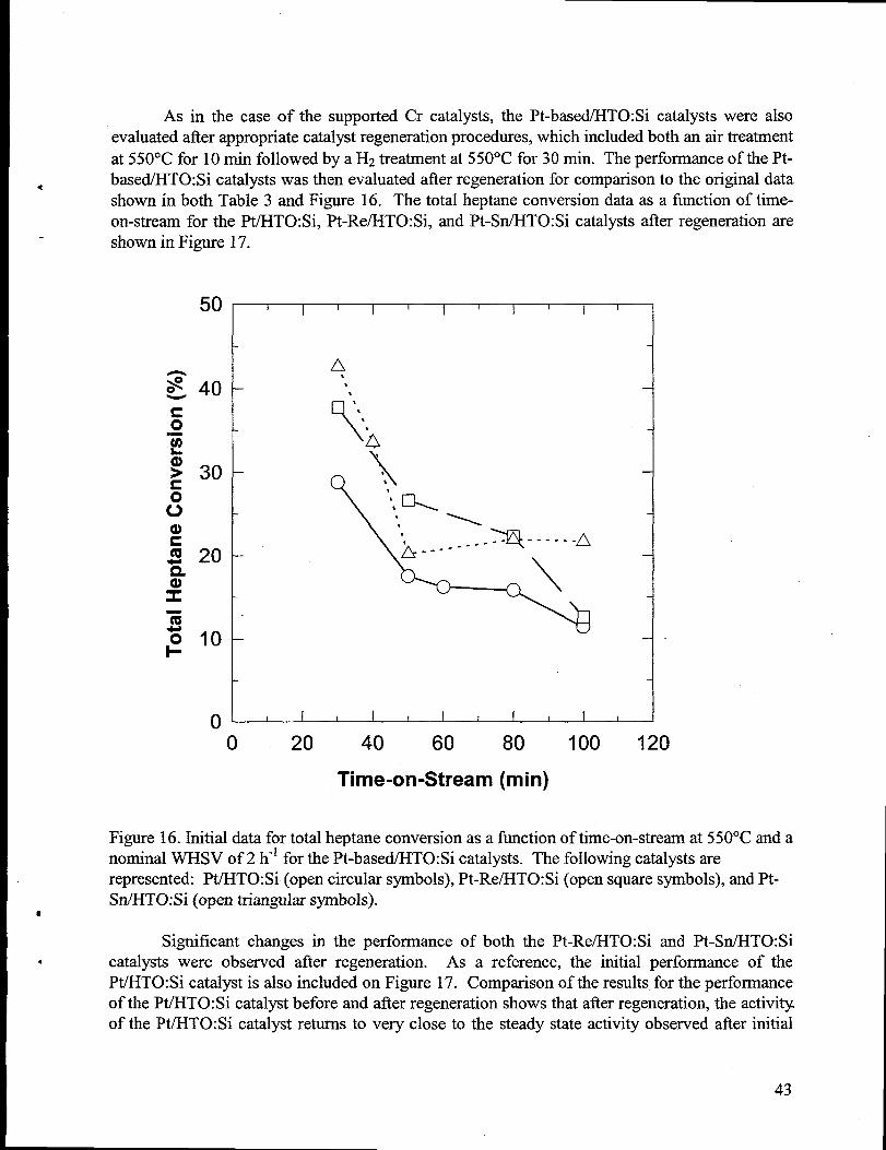
As in the case of the supported Cr catalysts, the Pt-based/HTO:Si catalysts were alsoevaluatedafter appropriatecatalystregenerationprocedures, which included both an airtreatmentat 550”C for 10 min followed by a H2treatmentat 550”C for 30 min. The pefiorrnance of the Pt-based/HTO:Si catalystswas then evaluated afterregenerationfor comparison to the original data
●
shown in both Table 3 and Figure 16. The total heptane conversion data as a function of time-on-stream for the Pt/HTO:Si, Pt-Re/HTO:Si, and Pt-Sn/HTO:Si catalysts afier regeneration areshown in Figure 17.
50
40
30
20
10
0
I I I I I I II
II
!
-1
I I 1 I I I I I I I I 1
0 20 40 60 80 100 120
Time-on-Stream (rein)
Figure 16. Initialdata for total heptane conversion as a fimction of time-on-streamat 550”C and anominal WHSV of 2 h-l for the Pt-based/HTO: Si catalysts. The following catalystsarerepresented: Pt/HTO:Si (open circular symbols), Pt-Re/HTO:Si (open squaresymbols), andPt-Sn/HTO:Si (open triangularsymbols).
●
Significant changes in the performance of both the Pt-Re/HTO:Si and Pt-Sn/HTO:Si* catalysts were observed after regeneration. As a reference, the initial performance of the
Pt/HTO:Si catalyst is also included on Figure 17. Comparison of the results for the performanceof the Pt/HTO:Si catalystbefore and after regeneration shows thatafterregeneration,the activityof the Pt/HTO:Si catalyst returnsto very close to the steady state activity observed after initial
43
deactivation (-15Y0 total heptane conversion). The high activity observed for the Pt/HTO:Sicatalyst in its initial clean state(-300/0 total heptaneconversion) is not approached by the catalystin its regenerated form. This might be due to incomplete removal of the carbonaceous depositsresponsible for catalyst deactivation during the regeneration procedure or due to significantsintering of the Pt particles during the air regeneration step. While other studies have reportedthatcareful passivation of supportedmetal catalystsis required prior to regenerationin oxidizingenvironments [46,87], our Pt-based/HTO:Si catalysts were exposed directly to air at elevatedtemperature (550”C) during the regeneration step. This may have resulted in a significanttemperatureexcursion and metalparticle sintering.
I I I I h I I I I I I
Q
.
.-
——
I I ! I I I I I I I 8
0 20 40 60 80 100 120
Time-on-Stream (rein)
Figure 17. Data for total heptaneconversion afterone regenerationcycle as a fimction of time-on-stream at 550”C and a nominal WHSV of 2 h-l for the Pt-based/HTO:Si catalysts. Thefollowing catalysts arerepresented: Pt/HTO:Si (filled circular symbols), Pt-Re/HTO:Si (filledsquare symbols), and Pt-Sn/HTO:Si (filled triangularsymbols). As a reference, the open circularsymbols represent the initialcatalystdeactivation data for the PtLHTO:Sicatalyst (from Figure16). The regeneration cycle consisted of a Nz purge for 10 min at 550”C, followed by an airtreatmentfor 10 min at 550”C, followed by a H2treatmentat 550°C for 30 min.
●
b
44
In the case of the Pt-Re/HTO:Si and Pt-Sn&ITO:Si catalysts, activity after catalystregeneration also did not approach the initial activity observed for the fresh catalysts (compareFigures 16 and 17). However, the initial activity of the regenerated Pt-Re/HTO:Si and Pt-Sn/HTO:Si catalysts was still significantly higher than that observed for the regeneratedPt/HTO:Si catalyst. The Pt-Re/HTO:Si catalyst again showed significant deactivation over the100 min time-on-stream period after air regeneration, with the final total heptane conversionvalues approaching those observed for the regeneratedPtfHTO:Si catalyst in its final deactivatedstate (100 min time-on-stream). Similar to the fi-eshcatalyst results, the Pt-Sn/HTO:Si catalystappeared to perform better after regeneration than both the Pt-Re/HTO:Si and the PtiHTO:Sicatalysts. Less overall deactivation was observed for this catalyst, with total heptane conversionvalues ranging from 15 to 25% for time-on-stream values up to 100 min. In addition to thepotential problems identified for the Pt/HTO:Si catalyst with respect to the regenerationprocedure (incomplete hydrocarbon removal and sintenng), the air oxidation procedure used forcatalyst regeneration can have significant detrimental effects on the Pt-Re and Pt-Sn alloyparticles. It would be expected that oxidationh-eductioncycling of such alloys might ultimatelyresult in segregation of the various alloying components, accompanied by the degradation or lossof catalystactivityor selectivity adva&ages [100,103,114].
Two final aspects of catalystdeactivationto be considered are the weight and surface areachanges for the various supported Pt-based catalysts. In contrast to the Cr/HTO:Si samplesdescribed previously, all of the Pt-based/HTO:Si samples were calcined (600°C/2b/air) prior totesting, so these materialswere expected to be very stable with respect to furtherweight loss andsurface area reduction in the reactor environment. This allowed the effmts of catalystdeactivation in terms of weight gain and surface area reduction to be directly measured. Theinitial sufiace areas of the calcined Pt-based/HTO:Si samples were -135 m2/g. Irrespective ofcomposition, all of the samples showed a surface areareduction as a result of catalysttesting andhad very similar surface area upon removal from the reactor (70-75 m2/g). All Pt-based/HTO:Sisamples showed a weight gain as a result of reactor testing, with weight gains ranging from 6-13wt.Yo. Interestingly,the alloyed Pt compositions (Pt-Re and Pt-Sn) showed a significantly largerweight gain (11-13 Wt.O/O)than the Pt/HTO:Si materials (6-8 Wt.O/O).We find this interestinginlight of the fact that the Pt-Sn/HTO:Si material apparently showed increased resistance tocatalystdeactivation (see Figures 16 and 17).
The Pt-basedJHTO:Si catalysts did show increased weight gain relative to the supportedCr catalystsevaluated. However, as mentioned previously, this is likely due to the selection of acommon reaction temperature(550”C) thatwas more suitable for optimum performance of thesupported Cr catalysts. This fact, combined with the lack of H2 in the feed (H2/n-heptaneratio =O),would have significantly enhanced catalystdeactivation in the case of thePt-based catalysts.
Summary
The efforts of this section were devoted to identifying high activity catalystmaterials foruse in n-heptane dehydrogenation/dehydrocyclization to toluene. In addition to evaluating acommercial catalystbenchmark (Girdler G-41 7.5 wt.’%oCr/y-A1203), HTO:Si-supported Cr and
45
Pt-based catalysts were also evaluated under identical conditions. The commercial Cr/y-AlzOqcatalyst was clearly more active than the Cr/HTO:Si catalysts, and the inability to increase theCr/HTO:Si catalyst activity through increases in Cr loading exacerbated the differences betweenthese materials. Pt/HTO:Si, Pt-Re/HTO:Si, and Pt-Sn/HTO:Si catalystswere also evaluated forn-heptane dehydrogenation/dehydrocyclization activity at conditions similar to those of thesupported Cr catalysts. Although several interesting trends were observed for the Pt-based/HTO:Si catalysts, because the reaction conditions were less optimum for supported Ptcatalysts, significant deactivation with increasing time-on-stream was observed, and overallcatalyst performance for these materials was not as good as the supported Cr catalysts.Continued investigation of Pt-basecUHTO:Si catalysts under more favorable reactor operatingconditions appears warranted,including the use of a relevant commercial Pt catalystbenchmarkand the carefil discrimination of thermal reactions and support acid site effects. Based on theseoverall bulk catalyst development results, the Girdler G-41 7.5 Wt.O/OCr/y-Alz03 catalyst wasselected as the catalyst of choice for packed bed application in the catalytic membrane reactorexperiments.
Chapter Ill. Catalytic Membrane Reactor Testing
Experimental
A baseline silica (A2** sol-derived) membrane was fabricated along the inside diameterof a6 cm long asymmetric aluminamembrane tube (1.0 cm OD and 0.7 cm ID) via dip coating (HzOcontent >10 ppm; stagnantatmosphere drying) as described in ChapterI. After calcination for 3h at 550”C, surface derivatization of the baseline silica membrane was accomplished, by dipcoating the tube in a TEOS monomer solution (5 volume 0/0TEOS in ethanol), and recalcining at525°C for 3 h. The final membrane would therefore be considered a composite silica membranesince two dip coating applications, utilizing different SOIS,were performed. For catalyticmembrane reactor testing, the membrane tube was packed with 1.34 g of a commercial 7.5 Wt. O/O
Cr/y-AlzOs catalyst (Girdler G-41) and heated to the reaction temperature (525 to 570”C) inflowing N2. Pure gas permeation tests were conducted at 525°C with hydrogen and nitrogen inbetween the catalytic membrane reactor tests. The procedure used for the catalytic membranereactor tests consisted of feeding n-heptane at weight hourly space velocities (WHSV) from 2-8h-l through the reactor for periods of 1.5 to 1.75 h and monitoring the effluent flow rate andhydrogen content of the residue and permeate gas streams. The partial pressure driving forcerequired for hydrogen permeation was obtained by operating the permeate side under a reducedpressure of approximately 0.07 atm, with tube side pressures (Pt) of 1 to 4 atm. The effluent gasstreamwas analyzed on-line using a gas chromatographyequipped with a TCD. Four analyses ofthe effluent gas streamswere made (generally 15-30 min apart) during each test period. Liquidresidue from the reactor was collected in chilled condensers located on both the permeate andresidue (retentate) lines. The liquid residue samples were collected at the end of each run (i.e.,-one liquid sample per run) and analyzed in a similar fashion to thatdescribed for the bulk catalyst
46
A
.
development activities in Chapter II. Following each run, the reactor was cooled to 450”C andthe catalyst was reactivated by passing air through the reactor for a period of 1 h. This is incontrast to the bulk catalyst testing with the Girdler G-41 catalyst, where catalyst regenerationwas performed at 550”C in air (see ChapterII).
The conventional packed bed reactor experimentsdescribed in ChapterII and these catalyticmembrane reactor experimentswere performed in different laboratoriesby separatepersonnel.This fact explains the subtle differences observed between the two data sets in terms of theexperimentalset-up and samplingprotocol, on-line product gas analysis,product liquidcollection, and regenerationprocedures.
Results and Discussion
In terms of membrane performance and stability, the microporous silica membranes appearto be a promising candidate for this application. No condensed liquids were collected on thepermeate side of the module which indicated thatheptane and toluene are too large to permeatethrough the pores of the silica membrane. This fact alleviated the need to impart a catalyticfimctionality into the membrane to convert unreactedheptane as it passed throughthe membrane.However, small quantities of CI-C4 hydrocarbons were detected in the permeate stream at allcatalytic membrane reactor operating conditions. The hydrogen concentration in the permeatestream was generally above 98 mole 0/0 so the membrane was able to effectively separatehydrogen from cracking products such as C 1-C4 hydrocarbons. For reference, the mole % of H2in the combined permeate and retentategas streamsat all reaction conditions was always greaterthan 70’%0,and generally in the 85-95% range. Generalizing over all catalytic membrane reactoroperating conditions, the order of decreasing hydrocarbon concentration in the permeate (orretentate)gas stream was CzH(j> CH4 > CJH8~ ZC4 species. Typical concentrations of thesehydrocarbon species in the permeate stream were nearly always less than 0.5 mole Yo.Condensed liquid products detected included toluene, dimethylcyclopentanes, heptenes,pentanes, and benzene, in order of decreasing concentration, similar to the results obtained in theconventional packed bed reactor testing with the Girdler G-41 catalyst (see Chapter II). Theapparentcorrelation between the gas and liquid product analyses indicated that hydrogenolysisreactions were occurring, with a higher preference of terminal bond scission relative to centralbond scission in the case of thesenonselective cracking reactions.
Table 4 shows the overall performance observed with the Girdler G-41 catalyst in thecatalytic membrane reactor for the n-heptane dehydrogenation/dehydrocyclization reaction as afimction of WHSV at a tube side pressure (P,) of 1 atm, a reactor temperatureof 550”C, and 60min nominal time-on-stream. As described earlier in Chapter II, the theoretical toluene yieldunderthe conditions of this study (550”C, 1 atmpressure) should be essentially 100 percent sincethere is no thermodynamic limitation on conversion. Because of this fact, the removal of productH2 by the membrane would not be expected to provide a significant conversion benefit.However, it was still important to determine whether the change in reactor configuration had asignificant effect on catalyst activity and selectivity. This comparison was possible over only alimited set of reactor operatingconditions (WHSV and Pt).
47
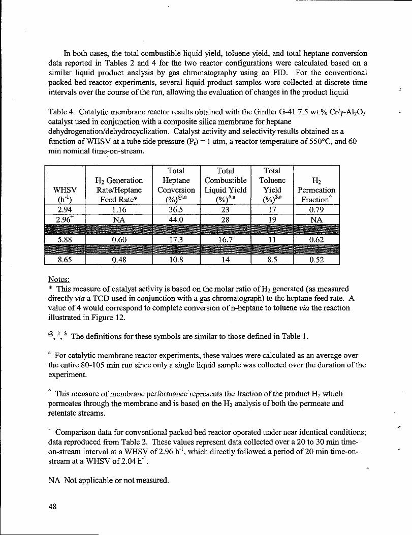
In both cases, the total combustible liquid yield, toluene yield, and total heptane conversiondata reported in Tables 2 and 4 for the two reactor configurations were calculated based on asimilar liquid product analysis by gas chromatography using an FID. For the conventionalpacked bed reactor experiments, several liquid product samples were collected at discrete timeintervalsover the course of therun, allowing the evaluation of changes in the product liquid
~,
Table 4. Catalytic membrane reactorresultsobtained with the Girdler G-41 7.5 wt.% Cr/y-A1203 -catalystused in conjunction with a composite silica membrane for heptanedehydrogenation/dehydrocyclization. Catalystactivity and selectivity resultsobtained as afunction of WHSV at a tube side pressure(P,) = 1 atm, a reactor temperatureof 550”C, and 60min nominal time-on-stream.
Total Total TotalH2 Generation Heptane Combustible Toluene H2
WHsv Rate/Heptane Conversion Liquid Yield Yield Permeation(h-]) Feed Rate* (%)@ja ~A)~j2 (%)$72 Fraction’2.94 1.16 36.5 23 17 0.792.96+ NA 44.0 28 19 NA
5.88
8.65 0.48 10.8 14 8.5 0.52
Notes.=S measure of catalystactivity is based on themolar ratio of H2generated(as measureddirectly via a TCD used in conjunction with a gas chromatography)to the heptane feed rate. Avalue of 4 would correspond to complete conversion of n-heptaneto toluene via the reactionillustratedin Figure 12.
@ # $ The definitions for these symbols are similar to those defined in Table 1.77
a For catalytic membrane reactor experiments, these values were calculated as an average overthe entire80-105 min run since only a single liquid sample was collected over the duration of theexperiment.
A This measure of membrane performance representsthe fraction of theproduct H2whichpermeates through the membrane and is based on the H2 analysisof both the permeate andretentatestreams.
+ Comparison data for conventional packed bed reactor operated undernear identical conditions; “datareproduced from Table 2. These values representdatacollected over a 20 to 30 min time-on-stream interval at a WHSV of 2.96 h-l, which directly followed a period of 20 min time-on-strearnat a WHSV of 2.04 h-l.
NA Not applicable or not measured.
48
*
composition with increasing time-on-stream. However, for the catalytic membrane reactorexperiments, only a single product liquid sample was collected over the entire 80-105 min run.These resultstherefore representan averageof catalystactivity and selectivity over the entirerun;this fact makes an evaluation of catalystdeactivation in the catalytic membrane reactor using theliquid product data impossible and also makes a comparison of the results for the two reactorconfigurations very difficult. Catalyst deactivation in the catalytic membrane reactor wasmonitored by evaluating catalyst activity via intermittentproduct gas streamanalysis (for H2 andC1-C4 hydrocarbons) using a TCD. Since this measurementwas only performed in the case ofthe catalyticmembrane reactor experiments,no direct link exists between this H2 generation dataand datameasured in the case of the conventional packed bed reactor configuration.
Based on the above discussion, a limited comparison can be made between the resultsobtained in the catalytic membrane reactor at a WHSV value of 2.94 h-l to those obtained at asimilar WHSV value (2.96 h-l) and operatingpressure(1 atm) for the Girdler G-41 catalyst testedin the conventional packed bed reactor (see Table 2; this data is reproduced in Table 4 for ease ofcomparison). For these similar operating conditions, the total combustible liquid yield and thetoluene yield for the catalytic membrane reactor are slightly less than those obtained in the caseof the conventional packed bed reactor. However, given the fact that the product liquid analysisin the case of the catalytic membrane reactor sample represents an average over a long timeinterval, significant catalyst deactivation would be expected. In terms of the total heptaneconversion, the decrease for the catalytic membrane reactor configuration relative to theconventional packed bed reactor is perhaps more significant, although the above statementregarding the sampling differences between the two reactor configurations applies in this case aswell. Overall, the differences in catalystactivity determined for the two unitsare relatively smalland easily within the limits of measurement error and extrapolation (in terms of catalystdeactivation effects). This provides a preliminary indication that the removal of H2 via thernicroporous composite silica membrane does not significantly affect catalyst performance atthese specific reaction conditions, although more carefhl experiments minimizing the samplingand analysis diffmences between the two reactor configurations would be necessary to providemore evidence to support this claim.
Table 4 also shows that an increase in space velocity results in a significant decrease incatalyst activity and product liquid selectivity. Similar to the discussion in ChapterII for tests inthe conventional packed bed reactor, the total heptane conversion in the catalytic membranereactor was roughly inversely proportional to the reactant flow rate (WHSV), validating theaw.imption of differential operating conditions. In addition to catalyst activity and selectivity,the petiormance of the membrane was evaluatedin terms of the fraction of generatedH2 thatwasseparatedfrom the retentatevia the microporous composite silica membrane. The lower WHSVvalues result in a larger ii-actionof the product H2 permeating through the membrane, which isconsistent with the longer residence time of the product gases in the catalytic membrane reactor.These overall results clearly indicate that even lower WHSV values are necessary to optimizecatalytic membrane reactor performance.
Similar to the results obtained for the conventional packed bed reactor configuratio~catalyst deactivation with time-on-stream was significant in the case of the catalytic membrane
49
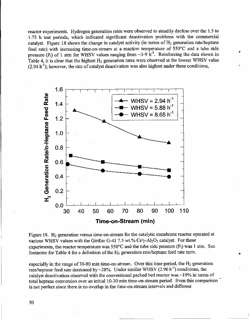
I
reactor experiments. Hydrogen generationrateswere observed to steadily decline over the 1.5 to1.75 h test periods, which indicated significant deactivation problems with the commercialcatalyst. Figure 18 shows the change in catalyst activity (in terms of Hz generation rate/heptanefeed rate) with increasing time-on-stream at a reaction temperature of 550”C and a tube sidepressure (Pt) of 1 atm for WHSV values ranging from -3-9 h-*. Reinforcing the data shown inTable 4, it is clear that the highest H2 generation rates were observed at the lowest WHSV value(2.94 h-l); however, the rateof catalystdeactivation was also highest under these conditions,
1.6 i I I I I I I I II
II
hI
I
1.4 -+ WHSV = 2.94 l-#
+ WHSV = 5.88 h-’+ WHSV = 8.65 h-’
1.2 -
1.0 -
:0.4 -
0.2 -
0.0 1 I 2 I I I I I I 1 I I I I t
30 40 50 60 70 80 90 100 11
Time-on-Stream (rein)
o
Figure 18. H2 generation versus time-on-stream for the catalytic membranereactor operated atvarious WHSV values with the Girdler G-41 7.5 Wt.O/OCr/y-A1203catalyst. For theseexperiments, the reactor temperaturewas 550°C and the tube side pressure(Pt)was 1 atm. Seefootnotes for Table 4 for a definition of the H2generation ratelheptanefeed rateterm.
especially in the range of 30-80 min time-on-stream. Over this time period, the H2 generationrateiheptanefeed rate decreasedby -28°/0. Under similar WHSV (2.96 h-l) conditions, thecatalystdeactivation observed with the conventional packed bed reactorwas -1 9°/0in terms oftotal heptaneconversion over an initial 10-30 min time-on-stream period. Even this comparison -is not perfect since there is no overlap in the time-on-stream intervalsand different
50
I
measurementsare involved. Additional discussion of catalystdeactivation observed with theconventional packed bed reactorconfiguration is detailed in ChapterII.
The effect of changing the tube side pressure (Pt) was examined in an effort to improvecataIytic membrane reactor performance. These experiments were performed at a high WHSVvalue (-8 h-l) with the results observed after =50 min time-on-stream being shown in Table 5.The data show that the production of Hz was optimized at Pt values ranging flom 2-3 atm, withthe percentage of hydrogen generatedin the dehydrocyclization reaction thatwas recovered in thepermeate streambeing high as long as the tube side (reactor) pressure (Pt)was above 1 atm. Thefraction of the Hz product which permeatedthrough the microporous composite silica membraneincreased significantly with increasing Pt values due to the increased driving force forpermeation/diffusion provided by the larger difference in pressure between the retentate andpermeate sides of the membrane. Nonselective cracking reactions were enhanced at higher Ptvalues and reaction temperatures;under these conditions, the permeate streamcontained a lowerH2purityand higher C1-C4 hydrocarbon concentrations.
Table 5. Catalytic membranereactorresultsobtained with the Girdler G-41 7.5 wt.% Cr/y-A1203catalystused in conjunction with a microporous composite silica membrane for heptanedehydrogenation/dehydrocyclization. H2generationand permeation rateswere obtained as afiction of tube side pressure(Pt) at a WSHV of 8 h-l, a reactor temperatureof 550”C, and 60min nominal time-on-stream.
Tube Side Pressure,Pt H2Generation Overall(atm.) Rate/HeptaneFeed Rate H2PermeationFraction
1.0 0.478 0.5172.0 0.595 0.757
3.0 0.572 0.79
I 4.0* 0.438 0.83
Note.=e datapoints for 4 atm. tube side pressure (Pt)representa different reaction temperature(570”C).
The effect of other catalytic membrane reactor operating conditions on catalyst deactivationwas also evaluated. In addition to the data shown in Table 5 regarding the effect of increasingtube side pressure (Pt), it was found that the rate of catalyst deactivation significantly increasedwith increasing reaction temperature. As might have been expected fi-om the data observed forthe conventional packed bed reactor (see Table 2), increases in reactor temperature(to 570”C)did not improve the product H2yield in the case of the catalytic membranereactor configuration,even when a higher tube side pressure (Pt = 3 atm) was utilized. The use of a lower reactiontemperature(525”C) was found to slightly decrease catalytic membrane reactor performance interms of H2 generation rate/heptanefeed rate and H2 permeation fiction. However, a highe;
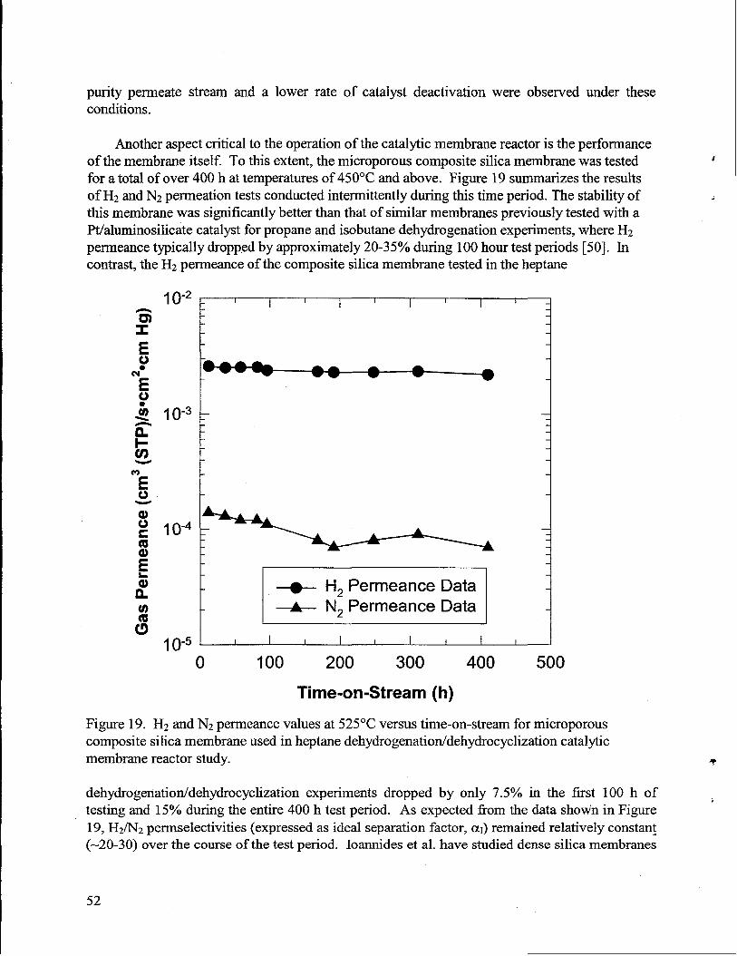
purity permeate stream and a lower rate of catalyst deactivation were observed under theseconditions.
Another aspect critical to the operation of the catalytic membrane reactor is the performanceof the membrane itself. To this extent, the microporous composite silica membrane was testedfor a total of over 400 h attemperaturesof 450”C and above. Figure 19 summarizesthe resultsof H2andN2permeation testsconducted intermittentlyduring this time period. The stabilityofthis membranewas significantlybetter thanthatof similar membranes previously testedwith aPt/aluminosilicate catalyst for propane and isobutane dehydrogenation experiments, where H2permeance typically dropped by approximately 20-35% during 100 hour testperiods [50]. Incontrast,the H2permeance of the composite silica membrane tested in the heptane
t
[r”’-== “ Iw 1“-5 1 I I I t I I I I
o 100 200 300 400 500
Time-on-Stream (h)
Figure 19. H2 and N2permeance values at 525°C versus time-on-stream for microporouscomposite silica membrane used in heptanedehydrogenation/dehydrocyclization catalyticmembrane reactor study.
dehydrogenation/dehydrocyclization experiments dropped by only 7.5% in the first 100 h oftesting and 15% during the entire 400 h test period. As expected from the data shoti in Figure19, H2/N2permselectivities (expressed as ideal separation factor, @ remained relatively constan~(-20-30) over the course of the test period. Ioarmideset al- have studied dense silica membranes
. I
T
;
52
prepared by chemical vapor deposition in various catalytic membrane reactor applications,including isobutane dehydrogenation, dry reforming (C02 reforming of methane), and partialoxidation of methane [53,54]. They observed lower H2 permeance for their membranes (0.3cm3/(cm2”min.atrn) or -6.6 x 10⁻⁵ cm3/(cm2”s”cm Hg) at 600°C) and better Hz/Nz
\ perrnselectivities (200-300) than the sol-gel derived microporous silica membranes evaluatedherein. Exposure to feeds containing H20 decreased membrane permeance significantly due to
. densification of the silica membrane [54]. Although our baseline silica membrane materialswould be susceptible to the same problems, it is hoped thatthe surface derivatizationapproachesused to tailor pore size in composite membrane materialsmight also impartincreased stability intermsof resistanceto densification in high temperatureenvironments containingH20.
Even though it was difficult to compare the overall rate of catalyst deactivation in thecatalytic membrane reactor with that observed in the conventional packed bed reactor, theimportant feature to note is that significant catalyst deactivation existed in either case. It mightbe expected that the removal of product H2 would fi.uther increase the rate of catalystdeactivation in the case of the catalytic membrane reactor, since a much smaller fraction of theproduct H2 remains available to prevent coking of the catalyst surface and subsequentdeactivation relative to the conventional packed bed reactor. Even ,tiough many authors havedemonstratedthat equilibrium conversion limitations can be exceeded using in situ H2 removal[12,14,19,47,50,52,54,55,61], catalyst deactivation problems related to this methodology havealso been documented [12,14,1 9,50,52,53]. Ali et al. [47] have demonstratedimprovements inconversion up to a factor of 4x (relative to equilibrium conversion values) for methylcyclohexanedehydrogenation to toluene in a packed bed reactor coupled with in silu H2 removal using acomposite Pd-Ag membrane. The largest improvements in conversion relativeto the equilibriumvalues were observed at lower temperaturesand higher pressures (up to 20 bars). This work andsubsequent modeling efforts were pefiormed using a pilot-scale unit under industriallyrelevantconditions.
Problems with catalyst deactivation due to in situ removal of H2 fromdehydrogenation/dehydrocyclization product streamshave led several researchersto propose andtest the use of ex situ H2 removal in conjunction with conventional packed bed reactors. BothRezac, et al. [51] and Ali, et al. [46,48] have demonstrated three stage reactor/membrane/reactorsystems where ex situ removal of H2 in the membrane only (no catalyst) stage was utilized toincrease conversions beyond equilibrium limitationswhile minimizing catalystdeactivation. It isinteresting to note that the former authors used a polymer-ceramic composite membrane toaccomplish H2 removal, while the latterauthorsused a Pd-Ag membrane. In principle, there isno reason that a microporous silica membrane could not be used with similar success in thismembrane only ex situ H2 removal stage. Matsuda, et al. [52] noted that for isobutanedehydrogenation in a catalytic membrane reactor, the performance of a Pt/A1203 catalyst
i deteriorated rapidly due to deactivation such that it was less active than a Cr/A1203 catalyst.Interestingly, Pt-Sn/A1203 catalysts performed significantly better in the catalytic membrane
, reactorthanPt/A1203catalysts,presumably due to suppression of coke formation [52].
Of special note is the work published by Ali and Baiker [46] on a three staggreactor/membrane/reactorsystem (with ex situ H2 removal in the membrane only stage) used for
53
n-heptane dehydrocyclization to toluene. Their work was performed using significantly diffmentreaction conditions than our work; a Pt catalyst was utilized at reaction temperatures of 400-440”C, 17 bar total pressure, Hz/n-CTHIGfeed ratio -2, and LHSV values ranging fi-om 1.2-1.9h-*. The largestdifference in overall conversion to toluene in their multistage system relative toequilibrium conversion values was observed at combinations of low LHSV values with lowreaction temperature. These authors also observed significant catalyst deactivation withincreasing time-on-stream, even though H2removal was not performed in direct conjunction withthe catalystbed. This deactivation was attributedto the low H2/n-heptanefeed ratios used fortheir experiments; Bournonville and Franck [69] recommend a H2/n-heptanefeed ratio range of3-10 for supported Pt catalysts. As pointed out in Chapter II, this is a delicate balance sinceincreasing the H2 content of the feed beyond an optimum value lowers dehydrocyclizationactivity and increases the likelihood of other possible reaction pathways(e.g., hydrogenolysis andisomerization). Another problem is that the rate of n-heptane dehydrocyclization tends towardzero as the partial pressure of H2 in the feed approaches zero; this explains why even ex-situremoval of H2 using an interstage membrane separator can pose deactivation problems,particularlyif the feed to the second packed bed reactor used in the three stage system of Ali andBaiker becomes H2 deficient. Since all of our experiments utilized neatn-heptane feeds with noadded H2, this may explain the severe catalystdeactivation problems we experienced in both ourconventional reactor and catalytic membrane reactor experiments. This overall finding suggeststhatthe development of new catalystswhich are less sensitive to the H2content of the feed and/orproduct stream(in the case of a multistagesystem) is an importantareaof futurework.
Summary
These preliminary catalytic membrane reactor experiments were a successfid proof ofconcept demonstration of the integration of the microporous composite silica membrane andconventional packed bed catalyst technologies. At industrially relevant space velocity values(WHSV = 3-8 h-*), yields of the desired heptane dehydrocyclization products (toluene and H2)were low. There are two main reasons for the low yields observed in our catalytic membranereactor experiments: 1) catalyst activity was relatively low for this reaction; and 2) catalystdeactivation occurred rapidly due to the removal of product hydrogen by the membrane. In orderto obtain higher yields with this catalyst,the reactor should be operatedat lower space velocity orin another,more effective reactor configuration. Since there are no thermodynamic limitationson conversion in this application, the main purpose of the membrane is to separate H2 fi-om theother gas species and not to provide an equilibrium shift. Therefore, a more promisingconfiguration would be to use a conventional reactor followed by a membrane separator. Sincefor this case there would be no hydrogen removal in direct conjunction with the catalyst bed,catalyst deactivation should be less of a problem in this “hybrid” reactor configuration. Otherpotential modifications to the currentscheme might include increasingthe partial pressure of Hzto the reactor and/or recycling a portion of the product H2 to help minimize catalyst deactivation.The inclusion of H2 in the reactor feed and as well as higher pressureoperating conditions in thecatalytic membrane reactor would more closely simulate industrialreforming conditions and alsoimpose equilibrium constraints for which the catalytic membrane reactor unit could provideadditional benefits.
54
i
These initial benchmarking experiments demonstrated that more active, selective, anddeactivation-resistantcatalysts are required to increase liquid product yield and H2 production.Initial membrane pefiormance was better than expected, especially in terms of membrane
1selectivity to H2 and overall membrane stability at high temperature reaction conditions overextended periods of time. The currentlimitationsimposed by relatively low catalystactivity and
. significant catalyst deactivation are important challenges which must be overcome before itwould be practical to produce a prototype catalytic membrane reactor to demonstrate thepracticalityof our H2generationscheme.
Overall Summary and Recommendations
Membrane development studies determined that it was not possible to replicate the“thermal cut-off’ behavior observed for baseline (solvent-templated) silica membranes. It waspossible to integrate ion-exchangeable HTO films into the structureof composite microporousceramic membranes, although the catalytic advantage of this integration was determined to beminimal. However, additional fimdamental studies related to microporous ceramic membranesled to the development of surfactant-templated silica membranes with orderedmicro/mesoporosity. Upon subsequent surface derivatization,” the resulting compositemembranes yield both higher flux and permselectivity to H2 than previous composite membraneoptions. These new composite membrane materials offer great promise for both membraneseparationand catalytic membrane reactor applications.
Relative to the n-heptane dehydrogenation/dehydrocyclization activity of the commercialbenchmark catalyst (Girdler G-41 Cr/y-A120~),the performance of Cr/HTO:Si catalysts is poordue to a fimdamental limitation of the Cr/HTO:Si technology. Although the results obtainedwith the Pt-based/HTO: Si catalysts were inferior to the commercial Cr/y-A1203 catalyst, thesepreliminary results should be considered promising since it is clear that the chosen reactoroperating conditions were more optimum for supported Cr catalysts. Continued investigation ofPt-based/HTO:Si catalystsunder more favorable reactor operating conditions appears warranted,including the use of a relevant commercial Pt catalystbenchmark and the careful discriminationof thermal reactions and support acid site effects. Regardless of the supported catalyst used inconjunction with a membrane separation system, it is clear that significant improvements in theactivity, selectivity, and deactivation resistance of these catalyst materialsare required to enablethe utilization of catalytic membrane reactorunitsfor chemical production.,.
The preliminary catalytic membrane reactor experiments were a successful proof of* concept demonstration of the integrationof the microporous ceramic membrane and conventional
packed bed catalyst technologies. Furtherwork with new optimized catalyst formulations thathave higher activity, selectivity, and deactivationresistance is clearlyjustified. This work shouldalso incorporate improvements to the microporous ceramic membrane materialswhere possible,
55
such as the new composite silica membrane materials produced via the surfactant-templating+surface derivatization route. Finally, in an effort to boost overall catalytic membrane reactorsystem performance, design changes which allow for e.xsitu H2 removal, the inclusion of H2 inthe feed, and/or the recycle of product H2 should be evaluated.
References
1. S. G. Chalk, “Is There a Continuing Role for the Federal Government in Fuel Cell R&D forTransportation?,” 1998 Fuel Cell Seminar, Book of Abstracts, sponsored by the Fuel CellSeminar Organizing Committee, Palm Springs, CA, November, 1998, pp. 222-225.
2. C. Borroni-Bird, “Automotive Fuel Cell Requirements,” Preprintsof the AnnualAutomotive Technology Development Customers’ Coordin~ion Meeting, Vol. 1, U.S.Departmentof Energy, Washington, DC, October, 1996.
3. P. B. Davis, “DOE Automotive Fuel Cell Development Prograq” Preprintsof the AnnualAutomotive Technology Development Customers’ Coordination Meeting, Vol. 1, U.S.Departmentof Energy, Washington, DC, October, 1996.
4. R. Espino, “Fuels Processing for PEM Fuel Cells – Fuels IndustryPerspective:’ Preprintsof the Annual Automotive Technolo~ Development Customers’ Coordination Meeting,PNGV Workshop on Fuel Processing for Proton Exchange Membrane (PEM) Fuel Cells,U.S. Department of Energy, Washington, DC, October, 1995.
5. R. A. Kost, “Hybrid Propulsion Systems Development; Preprintsof the AnnualAutomotive Technology Development Customers’ Coordination Meeting, Vol. 1, U.S.Departmentof Energy, Washington, DC, October, 1996.
6. E. H. Wakefield, History of Electric Automobile: Hybrid Electric Vehicles, SAEPublications, Warrendale, PA, 1998.
7. R. Kumar, “Overview of Fuel Processing Options for Polymer Electrolyte Fuel CellSystems; Preprintsof the Annual Automotive Technology Development Customers’Coordination Meeting, PNGV Workshop on Fuel Processing for Proton ExchangeMembrane (PEM) Fuel Cells, U.S. Departmentof Energy, Washington, DC, October, 1995.
.,
8. L. F. Brown, “A Survey of Processes for Producing Hydrogen Fuel from Different Sourcesfor Automotive-Propulsion Fuel Cells,” Los Alamos National LaboratoryReport, LA-13112-MS, Los Alarnos, NM, March, 1996.
< I
I
56
9.
11.
12.
13.
14.
15.
16.
17.
18.
19.
20.
21.
T. J. Flynn, R. M. Privette,M. A. Perna,K.E. Kneidel, D. L. King, and M. Cooper,“Compact Fuel Processor for Fuel Cell-Powered Vehicles: SAE PaperNo. 1999-01-0536.
J. C. Amphlett, K. A. M. Creber, J. M. Davis, R. F. Mann, B. A. Peppley, andD. M.Stokes, “Hydrogen Production by SteamReforming of Methanol for Polymer ElectrolyteFuel Cells,” Int.J. Hydrogen Energy, 19[2] (1994), pp. 131-137.
J. C. Amphlett, R. F. Mann, B. A. Peppley, P. R. Roberge, A. Roc@ues, and J. P.Salvador, “Simulation of a 250 kW Diesel Fuel Processor/PEM Fuel Cell System~’ J.Power Sources, 71 (1998), pp. 179-184.
H. P. Hsieh, “Inorganic Membrane Reactors,” Cat. Rev. - Sci. Eng., 33 (l&2) 1991, pp. 1-70.
J. N. Armor, “Challenges in Membrane Catalysis,” CHEMTECH, September, 1992, pp. ‘557-563.
G. Saracco, G. F. Versteeg, and V. P. M. van Swaaij, “CurrentHurdlesto the Success ofHigh TemperatureMembrane Reactors,” J. Membr. Sci., 95 (1994), pp. 105-123.
G. Saracco and V. Specchia, “Catalytic Inorganic Membrane Reactors: PresentExperienceand FutureOpportunities,” Catal. Rev.-Sci. Eng., 36[2] (1994), pp. 305-384.
J. N. Armor, “Membrane Catalysis: Where is it Now, What Needs to be Done?,” Cat.Today, 25 (1995), pp. 199-207.
J. Shu, B. P. A. Grandjean,A. Van Neste, and S. Kaliaguine, “CatalyticPalladium-BasedMembrane Reactors: A Review,” Canad. J. Chem. Eng., 69 (1991), pp. 1036-1060.
J. L. Falconer, R. D. Noble, and D. P. Sperry, “Catalytic Membrane Reactors,” in ~Handbook of Membrane Separations,S. A. Stem and R. D. Noble, Eds., Marcel Dekker,New York (1993).
E. Kikuchi, “Hydrogen-Permselective Membrane Reactors,” CATTECH, March, 1997, pp.67-74.
S. R. Vatcha, F. Tnfiro, and F. Cavani, “Oxidative Dehydrogenation and AlternateDehydrogenation Processes,” Catalytic Studies Division Report, Mountain View, CA,1993.
D. C. Grenoble and M. M. Estadt, “The Chemistry and Catalysisof the Water-Gas ShiftReaction. 1. The Kinetics Over Supported Metal Catalysts:’ J. Catal., 67 (1981), pp. 90-102.
.
57
22.
23.
24.
25.
26.
27.
28.
29.
30.
31.
32.
33.
M. J. Kahlich, H. A. Gasteiger,and R. J. Behm, “Kinetics of the Selective CO Oxidation inHz Rich Gas on Pt/AlzOg~’ J. Catal., 171 (1997), pp. 93-105.
R. F. Mann, J. C. Amphlett, and B. A. Peppley, “A Fuel Conditioning System for aMethanol Fuelled PEM Fuel Cell Power Generator,” in FrontiersScience Series, Number 7,T. Ohta and T. Homma, Eds., Universal Academy Press, 1993, pp. 613-618.
J. C. Amphlett, R. F. Mann, and B. A. Peppley, “On Board Hydrogen Purification forSteamReforrnation/PEM Fuel Cell Vehicle Power Plants;’ Int.J. Hydrogen Energy, 21[8](1996), pp. 673-678.
S. Gottesfeld, “Fuel PurityRequirements for PEM Fuel Cells,” Preprintsof the AnnualAutomotive Technology Development Customers’ Coordination Meeting, PNGVWorkshop on Fuel Processing for Proton Exchange Membrane (PEM) Fuel Cells, U.S.Departmentof Energy, Washington, DC, October, 1995.
J. L. Humphrey, “Separation Processes: Playing a Critical Role,” Chem. Eng. Progr.,October, 1995, pp. 31-41.
W. J. Koros, “Membranes: Learninga Lesson from Nature,” Chem. Eng. Progr., October,1995, pp. 68-81.
W. J. Koros and G. K. Fleming, “Membrane-Based Gas Separations,” J. Membr. Sci., 83(1993), p. 1.
R. Prasad, F. Notaro, and D. R. Thompson, “Evolution of Membranes in Commercial AirSeparation,” J. Membr. Sci., 94 (1994), pp. 225-248.
S. A. Stem, “Polymers for Gas Separations: The Next Decade,” J. Membr. Sci., 94 (1994),pp. 1-65.
J. Robeson, “Correlation of SeparationFactorVersus Permeabilityfor PolymericMembranes,” J. Membr. Sci., 62 (1991), pp. 165-185.
K. Keizer, R. J. R. Uhlhorn, V. T. Zaspalis, and A. J. Burggraaf, “Transport and Related(Gas and Vapour) Separationin Ceramic Membranes,” in Proceedings of the 2ndIntemational Congress on Inorganic Membranes, A. J. Burggraa~J. Charpin, and L. Cot,Eds., Trans Tech Publications, Zurich (1991), pp. 143-154.
R. J. R. Uhlhom, K. Keizer, and A. J. Burggraaf, “Gas-Transport and SeparationwithCeramic Membranes. 1. Multilayer Diffision and Capillary Condensation,” J. Membr. Sci.,66 (1992), pp. 271-287.
58
34.
i
35.*
36.
37.
38.
39.
40.
41.
42.
43.
44.
< 45.
C. J. Brinker, S. Wallace, N. K. Rarnan,R. Sehgal, J. Samuel, and S. M. Contakes, “Sol-Gel Processing of Amorphous Nanoporous Silicas: Thin Films and Bulk,” in Access inNanoporous Materials, T. J. Pinnavaia,andM. F. Thorpe, eds., PlenumPress, New York(1995), p. 123.
C. J. Brinker, R. Sehgal, N. K. Raman, S. K. Prakesh,and L. Delattre,“Sol-Gel Strategiesfor Controlled Porosity Ceramic Materials: Thin Film and Bulk,” Mat. Res. Sot. Symp.Proc., Vol. 368 (1995), p. 329.
C. J. Brinker,R. Sehgal, S. L. Hietala,R. Deshpande, D. M. Smith,D. Loy, and C. S.Ashley, “Sol-Gel Strategiesfor Controlled Porosity Inorganic Materials,” J. Membr. Sci.,94 (1994), p. 85.
L. C. Klein and N. Giszpenc, “Sol-Gel Processing for Gas SeparationMembranes: Bull.Am. Ceram. Sot.,69[11] (1990), pp. 1821-1830.
R. S. A. DeLange, J. H. A. Hekkink, K. Keizer, A. J. Burggraaf, “Formation andCharacterizationof Supported Microporous Ceramic Membranes Preparedby Sol-GelModification Techniques,” J. Membr. Sci., 99 (1995), pp. 57-75-
R. S. A. DeLange, J. H. A. Hekkink, K. Keizer, A. J. Burggraafi“Permeation andSeparationStudies on Microporous Sol-Gel Modified Ceramic Membranes,” MicroporousMater., 4[2-3] (1995), pp. 169-186.
T. Bein, “Synthesis and Applications of Molecular Sieve Layers andMembranes,” Chem.Mater., 8 (1996), pp. 1636-1653.
Y. Yan and T. Bein, “Zeolite Thin Films with Tunable Molecular Sieve Function; J. Am.Chem. Sot., 117 (1995), pp. 9990-9994.
Z. A. E. P. Vroon, K. Keizer, A. J. Burggraaf,and H. Verweij, “PreparationandCharacterizationof Thin Zeolite MFI Membranes on Porous SupportsJ’J. Membr. Sci., 144(1998), pp. 65-76.
Z. A. E. P. Vroon, K. Keizer, M. J. Gilde, H. Verweij, and A. J. Burggraaf,“TransportPropertiesof Alkanes Through Ceramic Thin Zeolite MFI Membranes,” J. Membr. Sci.,113 (1996), pp. 293-300.
A. J. Burggraa~ Z. A. E. P. Vroon, K. Keizer, and H. Verweq,.. “Permeation of Single Gasesin Thin Zeolite MFI Membranes,” J. Membr. Sci., 144 (1998), pp. 77-86.
K. Keizer, A. J. Burggraaf, Z. A. E. P. Vroon, and H. Verweij, “Two ComponentPermeation Through Thin Zeolite MFI Membranes,“J. Membr- Sci., 147 (1998), pp. 159-172.
59
46.
47.
48.
49.
50.
51.
52.
53.
54.
55.
56.
57.
58.
J. K. Ali and A. Baiker, “n-Heptane Reforming in a System of Reactors-InterstateMembrane to SeparateHydrogen,” Appl. Catal.A, 140 (1996), pp. 99-110.
J. K. Ali, E. J. Newson, and D. W. T. Rippin, “Exceeding Equilibrium Conversion with aCatalyticMembrane Reactor for the Dehydrogenation of Methylcyclohexane,” Chem. Eng. “Sci., 49(13) (1994), pp. 2129-2134.
~
J. K. Ali, D. W. T. Rippin, and A. Baiker, “Improving MethylcyclohexaneDehydrogenation with Ex-Situ Hydrogen Separationin a Reactor-InterstagedMembraneSystem,” Ind. Eng. Chem. Res., 34 (1995), pp. 2940-2948.
J. K. Ali, E. J. Newson, and D. W. T. Rippin, “Deactivation and Regeneration of Pg-AgMembranes for Dehydrogenation Reactions,” J. Membr. Sci-, 89 (1994), pp. 171-184.
J. P. Collins, R. W. Schwartz, R. Sehgal, T. L. Ward, C. J. Brinker, G. P. Hagen, and C. A.Udovich, “Catalytic Dehydrogenation of Propane in Hydrogen Permselective MembraneReactors,” Ind. Eng. Chem. Res.j 35 (1996), pp. 4398-4405.
M. E. Rezac, W. J. Koros, and S. J. Miller, “Membrane-Assisted Dehydrogenation ofNormal Butane,” Ind. Eng. Chem. Res., 34 (1995), pp. 862-868.
T. Matsuda, I. Koike, N. Kubo, and E. Kikuchi, “Dehydrogenation of Isobutane toIsobutene in a Palladium Membrane Reactor,” Appl. Catal. A., 96 (1993), p. 3.
T. Ioannides and G. R. Gavalas, “Catalytic Isobutane Dehydrogenation in a Dense SilicaMembrane Reactor;’ J. Membr. Sci., 77 (1993), pp. 207-220.
T. Ioannides and X. E. Verykios, “Application of a Dense Silica Membrane Reactor in theReactions of Dry Reforming and PartialOxidation of Methane,” Catal. Lett., 36 (1996), pp.165-169.
E. Gobina and R. Hughes, “Reaction Assisted Hydrogen TransportDuring CatalyticDehydrogenation in a Membrane Reactor,” Appl. Catal. A., 137 (1996), pp. 119-127.
B. A. Raich and H. C. Foley, “Supra-Equilibrium Conversion in Palladium MembraneReactors: Kinetic Sensitivityand Time Dependence~’ Appl. Catal. A., 129 (1995), pp. 167-188.
N. Itoh, “A Membrane Reactor Using Palladium,” AIChE J., 33[9] (1987), pp. 1576-1578.
N- Itoh, Y. Shindo, K. Haraya,and T. Hakuta,“A Membrane Reactor Using MicroporousGlass for Shifting-Equilibrium of Cyclohexane Dehydrogenation,” J. Chem. Eng. Jpn.,21[4] (1988), pp. 399-404.
J
60
59.
‘,, 60.
L
61.
62.
63.
64.
65.
66.
67.
68.
69.
71.
Y. L. Becker, A. G. Dixon, W. R. Moser, and Y.H. Ma, “Modelling of EthylbenzeneDehydrogenation in a CatalyticMembrane Reactor;’ J. Membr. Sci., 77 (1993), pp. 233-244.
A. Giroir-Fendler,J. Peureux, El.Mozzanega, and J.-A. Dalmon, “Characterizationof aZeolite Membrane for Catalytic Membrane Reactor Application;’ Stud. Surf. Sci. Catal.,101 (1996), pp. 127-136.
A.M. Champagne, T. T. Tsotsis, R. G. Minet, and I. A. Webster, “A High TemperatureCatalyticMembrane Reactor for EthaneDehydrogenationJ’ Chem. Eng. Sci., 45[8] (1990),pp. 2423-2429.
R. Sori~ “Overview on IndustrialMembranes,” Catal. Today, 25 (1995), pp. 285-290.
A. G. Saultand E. P. Boespflug, “Selective Dehydrogenation over Hydrous TitaniumOxide-Supported Catalysts,” SandiaNational Laboratories, SAND96-1 889, Albuquerque,1996.
A. G. Saultand E. P. Boespflug, “Selective Dehydrogenation of Ethylbenzene overHydrous Titanium Oxide-Supported Iron Catalysts;’ submitted to Ind. Eng. Chem. Res.Dev.
R. G. Dosch and L. 1.McLaughlin, “Hydrous Metal Oxide-Supported Catalysts: Part111.Development of NiMoHMO Catalysts,” SandiaNational Laboratories, SAND92-0388,Albuquerque, March, 1992.
S. E. Lott, T. J. Gardner,L. I. McLaughlin, and J. B. Oeltlce, “Evaluation of HydrousTitaniumOxide-Supported NiMo Catalystsfor Pyrene Hydrogenation and Upgrading Coal-Derived Liquids,” Fuel, 75[12] (1996), pp. 1457-1466.
R. Sehgal, “Microporous Gas SeparationMembranes: Fundamentals,Preparation,andCharacterization,”Ph. D. Dissertation, Universityof New Mexico, 1996.
J. Speight, The Chemistryand Technolo w of Petroleum, Second Edition, Marcel Dekker,New York (1991).
J.-P. Bournonville and J.-P. Franck, in Hydrogen Effects in Catalysis: FundamentalsandPractical Applications, Z. Paal and P. G. Menon, eds., Marcel Dekker, New York, 1988, pp.653-677.
C. J. Brinker, K.D. Keefer, D.W- Schaefer, and C. S. Ashley, “Sol-Gel Transition in SimpleSilicates;’ J. Non-Cryst. Sol., 48(1982), pp.47-64.
C. J. Brinker, A. J. Hurd, P. R. Schunk, G. C. Frye, and C. S. Ashley, “Review of Sol-Gel .Thin Film Formation,” J. Non-Cryst. Solids, 147-148 (1992), pp. 424-436.
61
72.
73.
74.
75.
76.
77.
78.
79.
80.
81.
82.
83.
62
H. P. Stephens and R. G. Dosch, “Catalyst Preparationvia Hydrous Metal Oxide Ion-Exchangers,” Stud. Surf. Sci.Catal.,31 (1987), pp. 271-283.
R. G. Dosch, H. P. Stephens,F. V. Stohl, B. C. Bunker, and C. H. F. Peden, “HydrousMetal Oxide-Supported Catalysts: Part I. PreparationChemistryand Physical andChemical Properties:’ SandiaNational Laboratories, SAND89-2399, Albuquerque, 4February, 1990.
Y. Lu, R. Ganguli, C. A. Drewien, M. T. Anderson, C. J. Brinker,W. Gong, Y. Guo, H.Soyez, B. Dunn, M. H. Huang, and J. I. Zink, “Continuous Formation of Supported Cubicand Hexagonal Mesoporous Films by Sol-Gel Dip Coating,” Nature,389 [25] (1997), p.364.
G. C. Frye, A. J. Ricco, S. J. Martin, and C. J. Brinker, “Characterizationof the SurfaceArea and Porosity of Sol-Gel Films Using SAW Devices~’ Mat. Res. Sot. Syrnp.Proc., 121(1988), pp. 349-354.
C. J. Brinker, N. K. Raman, M. N. Logan, R. Sehgal, R. A. Assink, D.-W. Hua, T. L. Ward,“Structure-PropertyRelationships in Thin-Films and Membranes:’ J. Sol-Gel Sci. Technol.,4 (1995), pp. 117-133.
C. J. Brinker, T. L. Ward, R. Sehgal, N. K. Raman, S. L. Hietal~ D. M. Smith, D.-W. Hua,and T. J. Headley, “Ultramicroporous Silica-Based Supported InorganicMembranes,” J.Membr. Sci., 77 (1993), pp. 165-179.
N. K. Raman, M. T. Anderson, and C. J. Brinker, “Template-Based Approaches to thePreparationof Amorphous, Nanoporous Silicas,” Chem. Mater., 8 (1996), p. 1682.
G. Cao, Y. Lu, L. Delattre,C. J. Brinker, and G. P. Lopez, “Amorphous Silica MolecularSieving Membranes by Sol-Gel Processing,” Adv. Mater., 8 [7] (1996), p. 588.
N. K. Raman and C. J. Brinker, “Organic Template Approach to Molecular-Sieving SilicaMembranes,” J. Membr. Sci., 105(1995), pp. 273-279.
Tsai, C.-Y., C. J. Brinker, “Silica Gas SeparationMembranes Preparedwith Surfactant-Templated Sublayers,” Proceedings of the Fifth InternationalConference on InorganicMembranes, Nagoy~ Japan(1998), pp.180-183.
L. S. White, T. A. Blinka, H. A. Kloczewski, and I. S. Wang, “Properties of a Polyimide rGas Separation Membrane in Natural Gas Streams,” J. Membr. Sci, 103 (1995), pp. 73-82.
R. G. Dosch, H. P. Stephens,and F. V. Stohl, “Hydrous Metal Oxide-Supported Catalysts:.
PartII. Catalytic Propertiesand Applications,” SandiaNational Laboratories, SAND89- - I2400, Albuquerque, February, 1990.
84. S. E. Lott, T. J. Gardner,and L. I. McLaughlin, “Screening of Hydrous Metal Oxide-Supported Catalystsfor NOX Reduction by Hydrocarbons in Oxidizing Environments:SandiaNational Laboratories, SAND96-2267, Albuquerque, September, 1996.
85. A. G. Sault, E. P. Boespflug, A. Martino, and J. Kawoia, “Selective Dehydrogenation ofPropane Over Novel Catalytic Materials,” SandiaReport, SAND 98-0435, Albuquerque,February, 1998.
86. H. Pines, The Chemistry of CatalyticHydrocarbon Conversions, Academic Press, NewYork, 1981, Ch. 4, Dehydrogenation and Cyclodehydrogenation (Aromatization), pp. 185-212.
87. H. Steiner, “Catalytic Cyclization and Aromatization of Hydrocarbons:’ in Catalysis, Vol.4, P. H. Emmett, cd., Rheinhold, New York, 1956, pp. 529-560.
88. G. C. Bond, Heterogeneous Catalysis: Principles and Abdications, Second Edition,Clarendon Press, Oxford, 1987.
89. Z. Paal, “Hydrogen Effects in SkeletalReactions of Hydrocarbons over Metal Catalysts; inHydrogen Effects in Catalysis: Fundamentalsand Practical Applications, Marcel Dekker,Inc., New York, 1988, pp. 449-497.
90. V. Ponec, “Catalysis by Alloys in Hydrocarbon Reactions,” Adv. Catal., 32 (1983), pp.149-214.
91. J. H. Sinfelt, Bimetallic Catalysts: Discoveries, Concepts, and Applications, John Wileyand Sons, New York, 1983.
92. E. H. Broekhoven and V. Ponec, “Mechanism of SkeletalReactions of Hydrocarbon onMetals,” Prog. Surf. Sci., 19(4) (1985), pp. 351-400.
93. United Catalysts, Inc., Products Catalog.
94. K. K. Kearby, “Catalytic Dehydrogenation,“ in Catalysis, P. H. Emmett, cd., Vol. 3,Reinhold, New York (1955), pp. 453-491.
95. E. F. G. Herrington and E. K. Rideal, “On the Catalytic Cyclization of AIiphaticHydrocarbons. I.,” Proc. Roy. Sot. A., 184 (1945), pp. 434-446.
96. C. F. Baes, Jr., and R. E. Mesmer, The Hydrolysis of Cations, JohnWiley and Sons, NewYork, 1976.
63
97.
98.
99.
100.
101.
102.
103.
104.
105.
106.
107.
S. M. Davis, F. Zaer~ and G. A. Samorjai, “Surface Structureand TemperatureDependence of n-Hexane SkeletalRearrangementReactions Catalyzed Over PlatinumSingle Crystal Surfaces: Marked StructureSensitivity of Aromatization:’ J. Catal., 85(1984), pp. 206-223.
R. W. Joyner,B. Lang, and G. A. Samorjai, “Low Pressure Studiesof Dehydrocyclizationof n-Heptaneon PlatinumCrystal SurfacesUsing Mass Spectrometry,Auger ElectronSpectroscopy, and Low Energy Electron Diffraction,” J. Catal., 27 (1972), pp. 405-415.
W. D. Gillespie, R. K. Herz, E. E. Petersen,and G. A. Samorjai, “The StructureSensitivityof n-HeptaneDehydrocyclization and Hydrogenolysis Catalyzed by Platinum SingleCrystalsat Atmospheric Pressure,” J. Catal., 70 (198 1), pp. 147-159.
S. M. Stagg, C. A. Querini, W. E. Alvarez, and D. E. Resasco, “IsobutaneDehydrogenationon Pt-Sn/Si02 Catalysts:Effect of PreparationVariables and Regeneration Treatments,” J.Catal., 168 (1997), pp. 75-94.
J. M. Hill, R. D. Cortright,and J. A. Durnesic, “Silica- and L-Zeolite-Supported Pt, Pt/Sn,andPt/SniK Catalystsfor IsobutaneDehydrogenation,” Appl. Catal.A, 168 (1998), pp. 9-21.
R. D. Cortrightand J. A. Dumesic, “L-Zeolite-Supported Platinumand Platinum/TinCatalystsfor IsobutaneDehydrogenation,” Appl: Catal. A, 129 (1995), pp. 101-115.
R. Prestvik, K. Moljord, K. Grande, and A. Holmen, “The Influence of Pretreatmenton theMetal Function of a Commercial Pt-Re/A120~Reforming Catalyst,” 174 (1998), pp. 119-129.
R. Prestvik, B. Tatdal, C. E. Lyman, and Anders Holrnen, “Bimetallic Particle Formation inPt-Re/A1203Reforming CatalystsRevealed by Energy Dispersive X-Ray Spectrometry inthe Analytical Electron Microscope,” J. Catal., 176 (1998), pp. 246-252.
J. L. Carter,G. B. McVicker, W. Weissman, W. S. Kmak, and J. H. Sinfelt, “BimetallicCatalysts: Application in Catalytic Reforming:’ Appl. Catal. 3 (1882), pp. 327-346.
L. Tournayan,R. Bacaud, H. Charcosset, and G. LeClercq, “Conversion of n-Heptane onPlatinum-Rhenium/Alumina Catalystsin Hydrogen at 400”C,” J. Chem. Res., Miniprint(1978), pp. 3582-3595.
M. Garland,A. Baiker, and A. Wokaun, “Alumina-Supported Platinum-Rhenium FDehydrogenation Catalysts: Influence of Metal Ratio and Precursorson CatalyticBehavior,” Ind. Eng. Chem. Res., 30 (1991), pp. 440-447. J
64
108.
109.
s
110.
111.
112.
113.
114.
t
D. C. Grenoble, “The Chemistryand Catalysisof the Toluene HydrodealkylationReaction.I. The Specific Activities and Selectivities of Group VIIB and Group VIII Metals Supportedon Alumina., J. Catal., 56 (1979), pp. 32-39.
C. Betizeau, G. Leclercq, R. Maurel, C. Bolivar, H. Charcosset, R. Frety, and L. Tournayan,“Platinum-Rhenium-Alumina Catalysts.III.Catalytic Properties,” J. Catal., 45 (1979), pp.179-188.
Z. Paal, M. Muhler, and K. Matusek, “Sulfided Pt Catalysts: Monitoring Surface ChemicalStateand CatalyticProperties in n-Hexane Reactions,” J. Catal., 175 (1998), pp. 245-251.
J. K. Ali and D. W. T. Rippin, “Comparing Mono- and Bimetallic Noble Metal Catalystsina CatalyticMembrane Reactor for Methylcyclohexane Dehydrogenation,” Ind. Eng. Chem.Res., 34 (1995), pp. 772-729.
T. Fukunagaand V. Ponec, “On the Role of Additives to PlatinumCatalystsfor ReformingReactions,” Appl. Catal.A, 154 (1997), pp. 207-219.
B. E. Spiewiak, P. Levin, R. D. Cortrightand J. A. Dumesic, “Microcalorimetric andReaction Studiesof Alkali Metals on Pt Powder andPt/SiOz, and Pt/Sn/SiOz Catalysts,” J.Phys. Chem., 100 (1996), pp. 17260-17265.
T. P. Chojnacki and L. D. Schmidt, “Microstructure of Pt-Sn and Rh-Sn Particleson
Si02,” J. Catal., 129 (1991), pp. 473-485.
65 I
DISTRIBUTION:
2 John P. CollinsAmoco Research CenterMail Code E-lE150 West Warrenville Rd.Napierville, IL 60563
1 MS 018810 MS 07101 MS 07101 MS 07101 MS 07102 MS 13492 MS 13492 MS 13491 MS 13492 MS 14521 MS 90182 MS 08991 MS 0619
LDRD Office, 4001Timothy J. Gardner, 1841Linda I. McLaughlin, 1841James E. MilIer, 1841Alan P. Sylwester, 1845C. Jeffrey Brinker, 1831Allen G. Sault, 1841C.Y. Tsai, UNMAlan J. Hurd, 1841Elaine P. Boespflug, 1552CentralTechnical Files, 8940-2Technical Library, 4916Review and Approval Desk, 15102For DOE/OSTI
3
66