Embed Size (px)
Citation preview
cellF Voice PCB Build Guide vers.1.3
nonlinearcircuits
updated 24/3/2015 This PCB was developed for the cellF project, which is basically a large analogue modular played by a dish full of
living neurons.
It is intended to be a complete ‘voice’ panel to be supported by a panel for sequencing and pattern generation.
Some of the circuits have been sold as individual PCBs previously, so the build manuals for these can be checked for
further information, if necessary. The main difference is all of the resistors (except 4) and ICs are surface mount. You
can use 1206 or 0805 resistors; my boards have a mix of both.
Some resistors are marked with “*”, just install the value indicated. For example, if you see 33k*, just install 33k. I
use the asterisks to indicate components they may need some experimenting with different values to get the best
performance. Generally it is only the components associated with vactrols that may need to be adjusted as the vactrols
have such broad tolerance ratings. This will be described in the relevant module build notes.
Pretty much all the components, except the vactrols, tempco resistors, 10uFBP, reverb tank and NJM13700s can be
bought from Tayda Electronics for a few cents or so.
Short description of the modules:
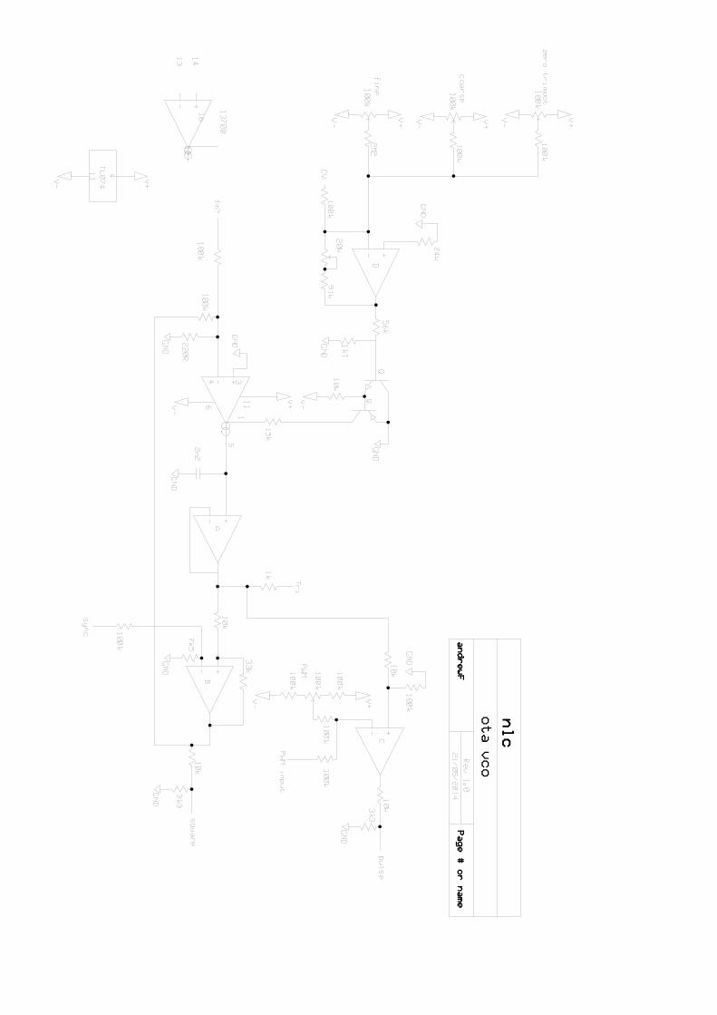
2 VCOs
These are very simple triangle core, OTA based designs, with triangle and pulse outputs. One has a soft sync input, the
other a FM input. You can actually experiment by inserting various CVs and other signals into these for different
effects. The cv/10 inputs divide the incoming CV signal to a tenth of its original voltage, this means you can use a +/-
5V signal to modulate the VCO over a few notes rather than several octaves.
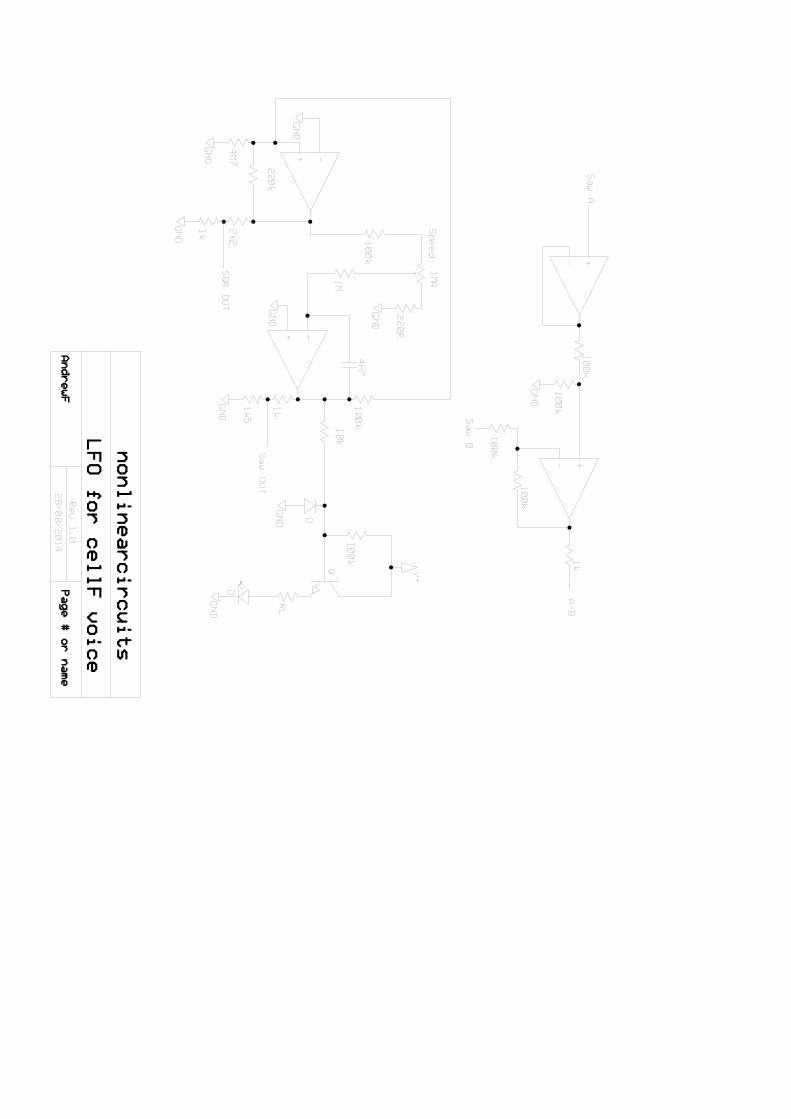
DUAL LFO
These are two separate LFO modules both giving square and sawtooth outputs, the frequency range depends on the
capacitors you choose, 4.7nF gives from approx. 0.05Hz to 90Hz, you can use larger capacitors to operate at lower
frequencies (say 6.8nF or 10nF). The LFOs share a dual LED, this needs to be a common cathode type. There is also
an ‘A-B’ output; this is a difference circuit, where the output is the difference in voltage levels between the sawtooth
outputs of LFO A and LFO B.
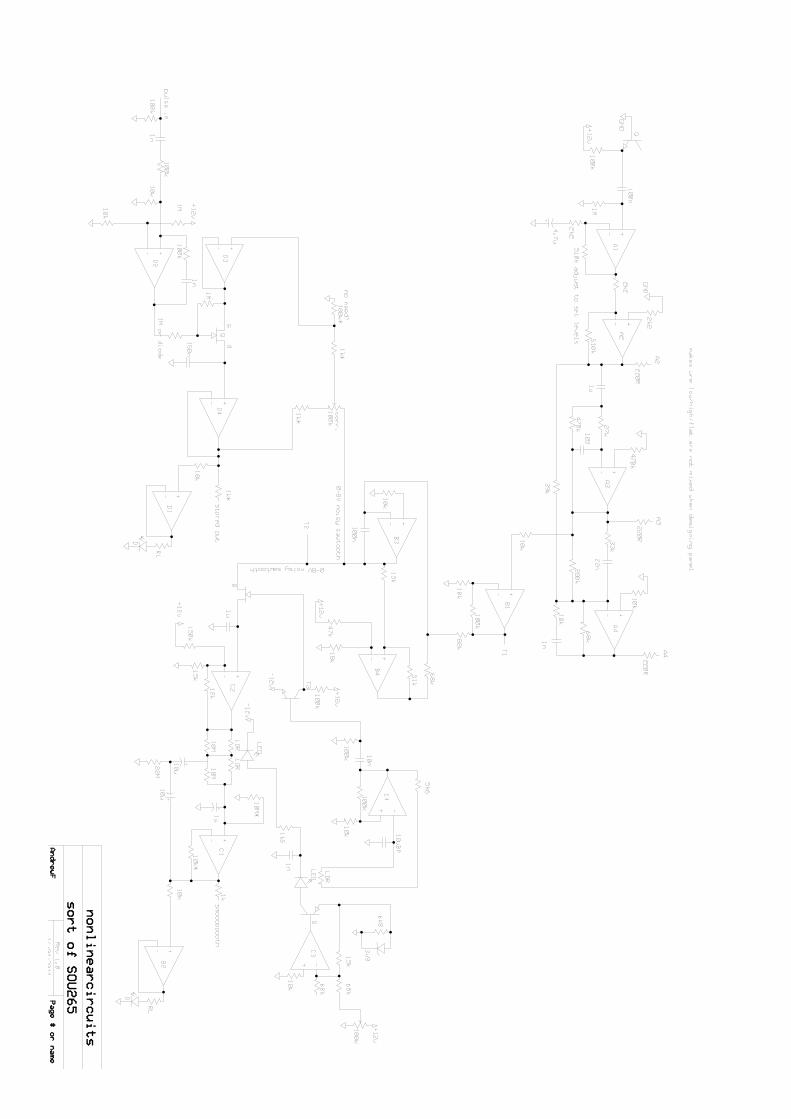
Sauce of Unce
This is a reworking of the Buchla 265 Source of Uncertainty. The original circuit contained a number of obsolete
components, so was broken down into a set of functions and these were redesigned using standard readily-available
components.
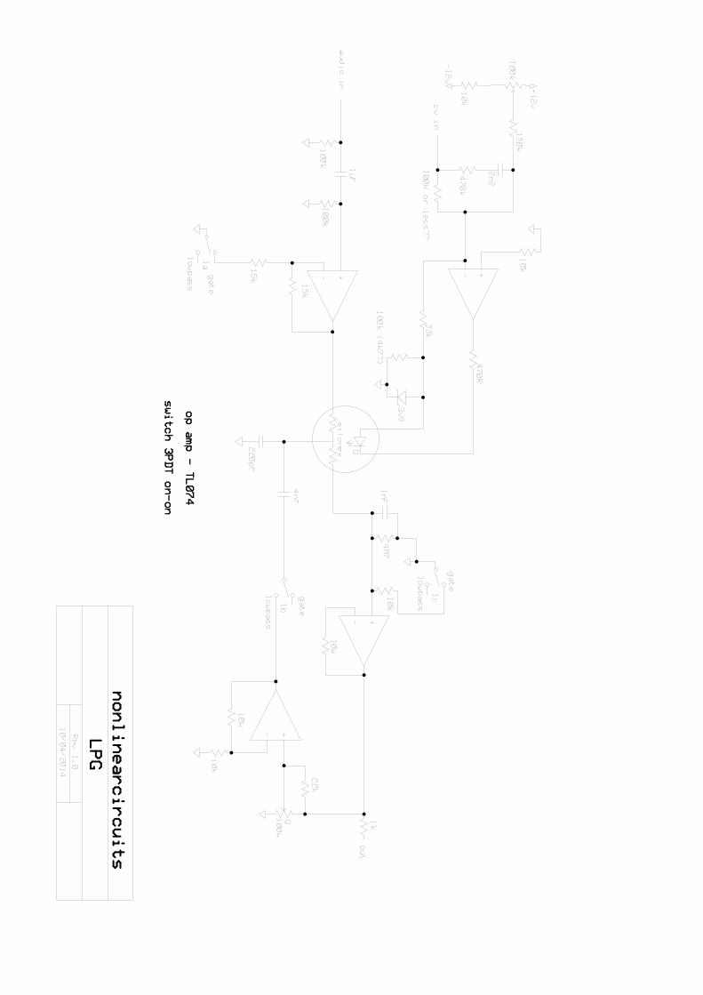
2 LPGs
Based on the Buchla Low Pass Gate with some changes to the feedback circuit and cutoff controls to get it to go lower
and control when it squeals.
Dif-rect
This is a slimmed down version of the Difference Rectifier, found on the NLC Neuron PCBs. It can be used for
mangling CVs, audio wave-shaping, ring-mod type effects and as a crude VCA.
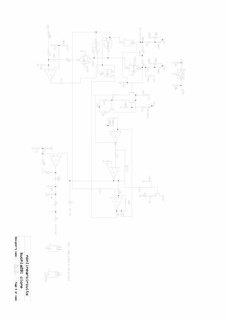
2 Envelope Generators
Based on the Buchla 281Function Generators; will self-oscillate, so long as you patch the pulse out into the gate input
when the LED is on, just like the original.
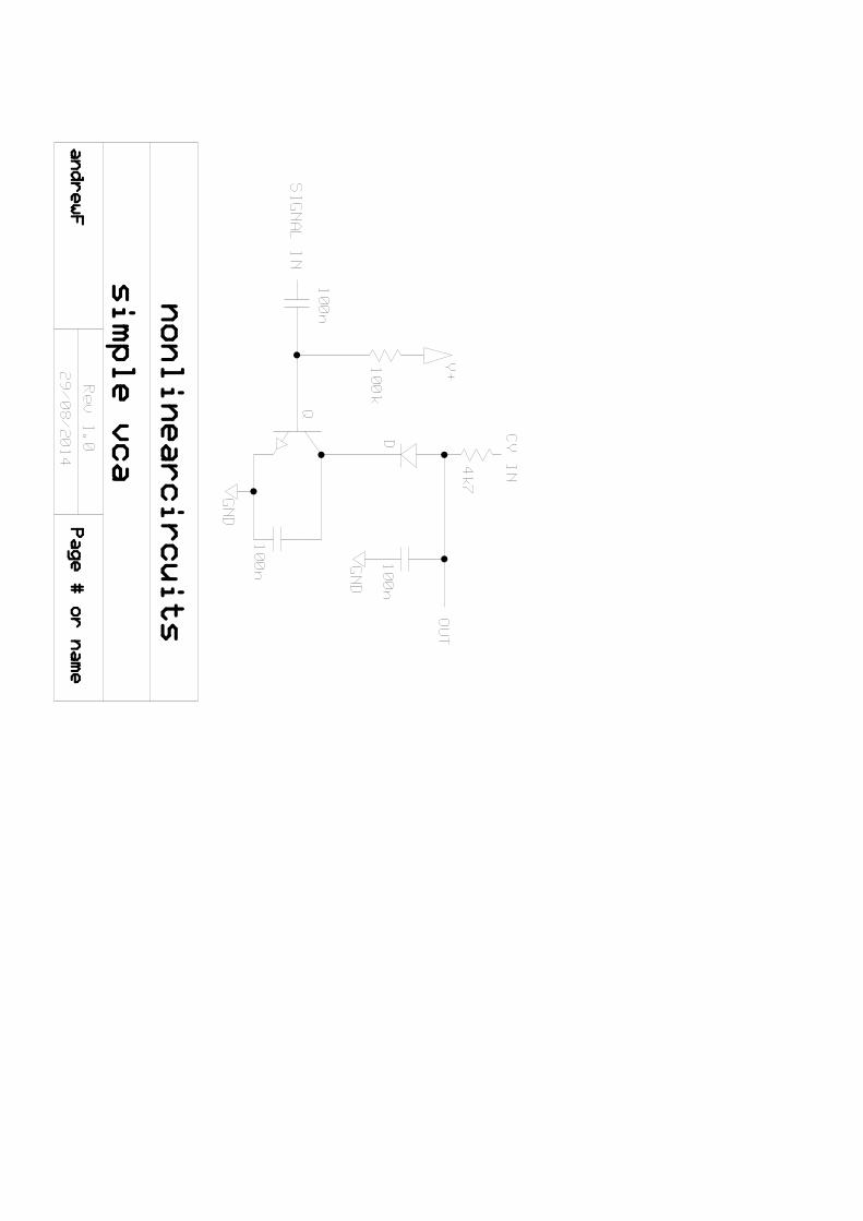
single VCA
This is a very basic VCA intended to be used with CVs rather than audio…..although it can be used for audio if you
like.
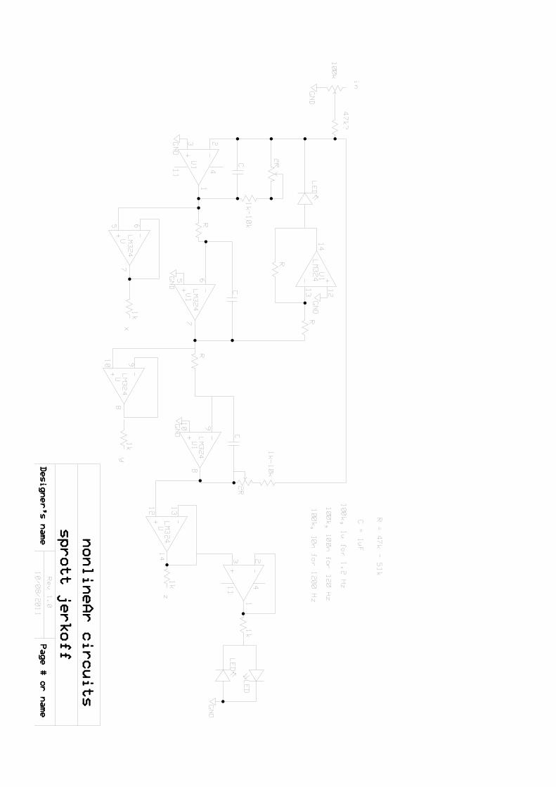
Chaos
This is a version of the NLC Jerkoff chaos circuit
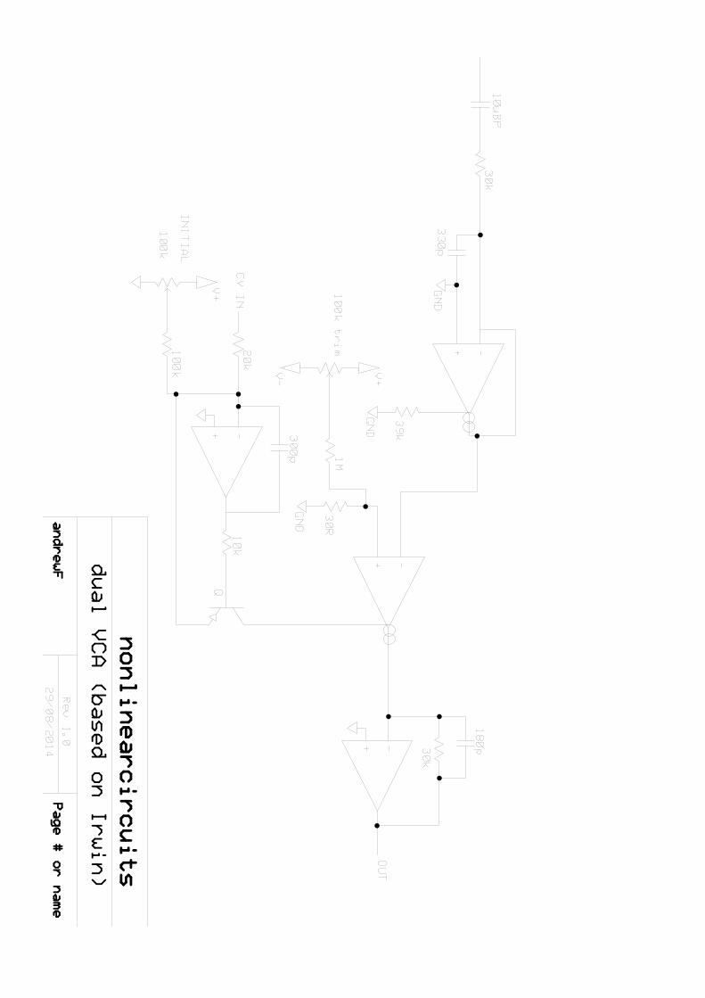
Dual VCA
These are two low-noise, high quality VCAs based on the Mike Irwin design
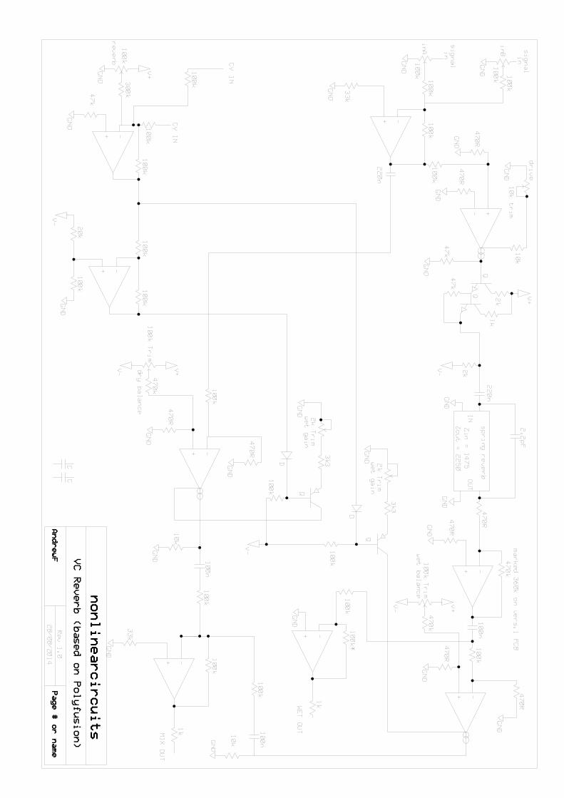
VC Reverb
This is a voltage controlled reverb module, based on the Polyfusion design. You need to obtain a particular reverb tank
for this design, detailed in the BOM
BOM
Component Quantity Comments 3.5mm mono sockets 60 must be Kobiconn or similar (the ones from Tayda will fit)
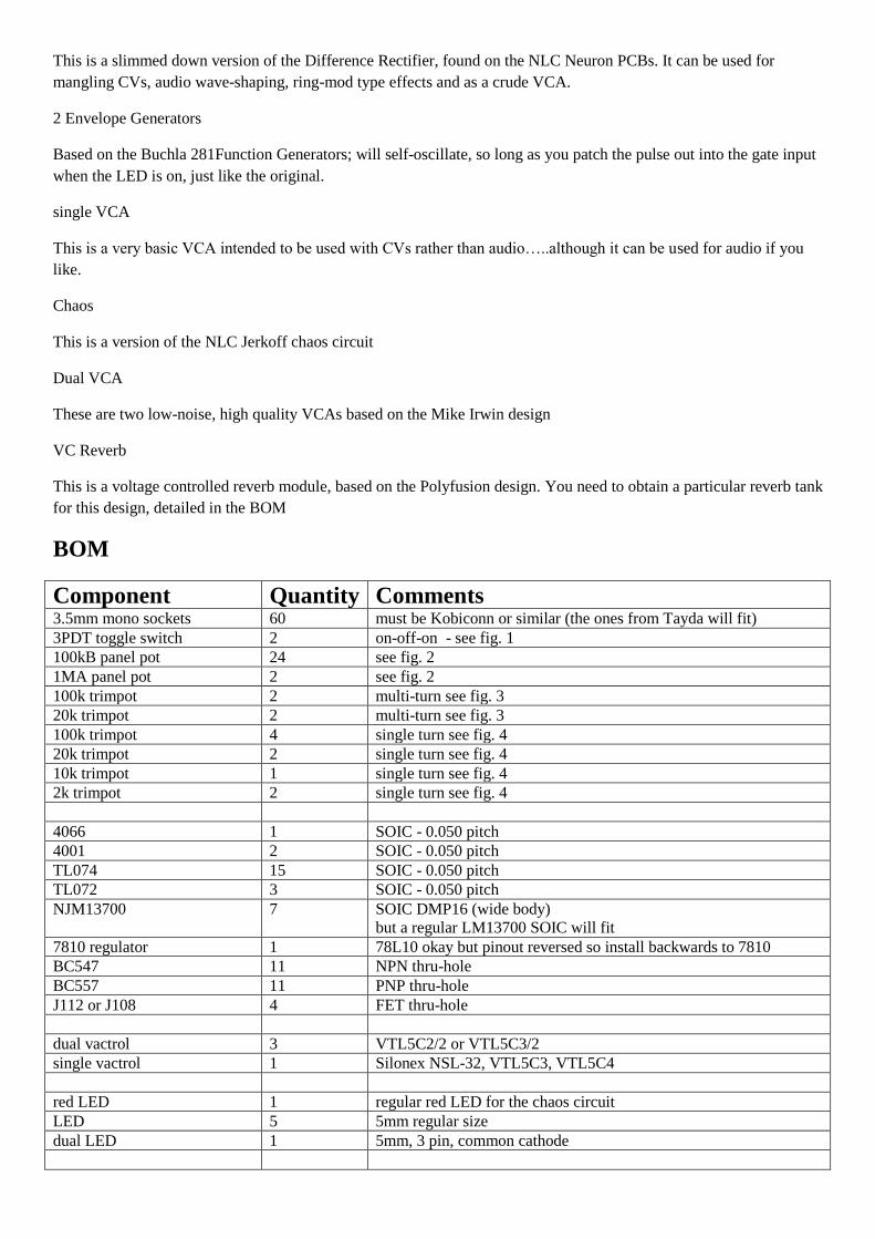
3PDT toggle switch 2 on-off-on - see fig. 1
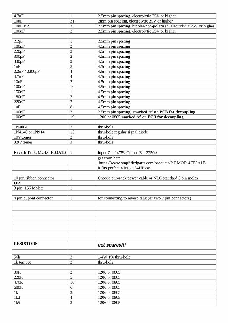
100kB panel pot 24 see fig. 2
1MA panel pot 2 see fig. 2
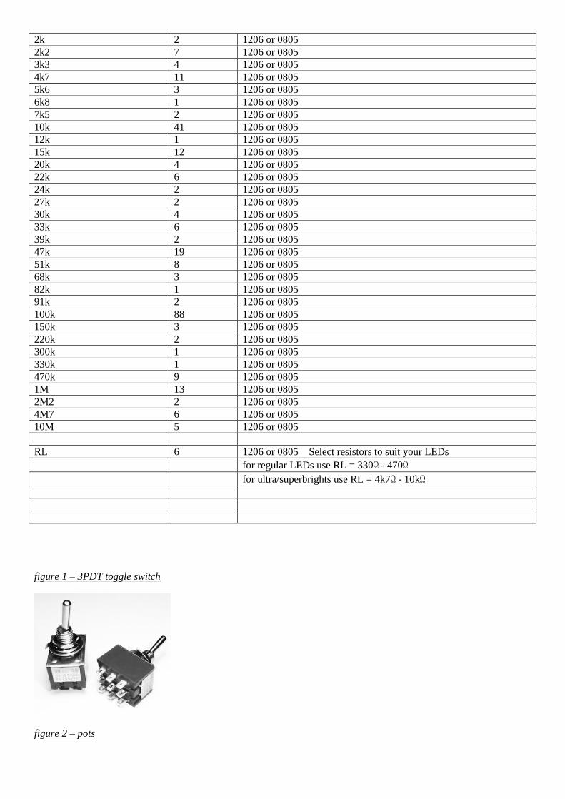
100k trimpot 2 multi-turn see fig. 3
20k trimpot 2 multi-turn see fig. 3
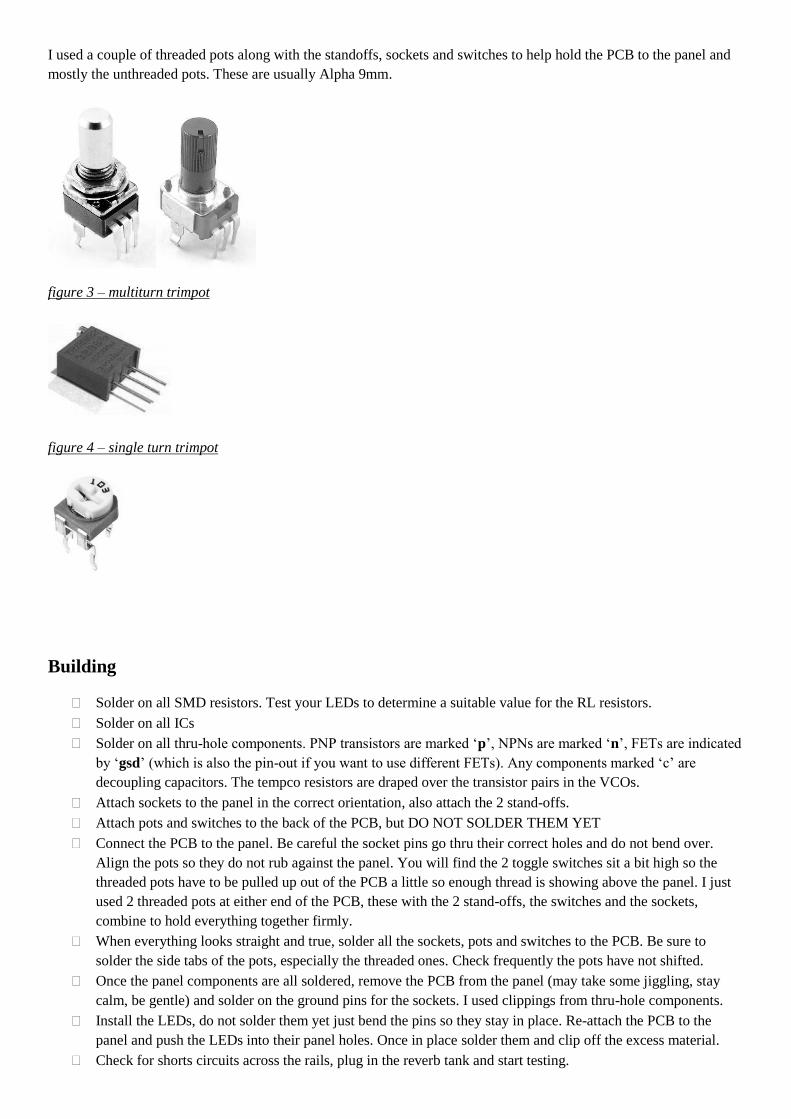
100k trimpot 4 single turn see fig. 4
20k trimpot 2 single turn see fig. 4
10k trimpot 1 single turn see fig. 4
2k trimpot 2 single turn see fig. 4
4066 1 SOIC - 0.050 pitch
4001 2 SOIC - 0.050 pitch
TL074 15 SOIC - 0.050 pitch
TL072 3 SOIC - 0.050 pitch
NJM13700 7 SOIC DMP16 (wide body)
but a regular LM13700 SOIC will fit
7810 regulator 1 78L10 okay but pinout reversed so install backwards to 7810
BC547 11 NPN thru-hole
BC557 11 PNP thru-hole
J112 or J108 4 FET thru-hole
dual vactrol 3 VTL5C2/2 or VTL5C3/2
single vactrol 1 Silonex NSL-32, VTL5C3, VTL5C4
red LED 1 regular red LED for the chaos circuit
LED 5 5mm regular size
dual LED 1 5mm, 3 pin, common cathode
4.7uF 1 2.5mm pin spacing, electrolytic 25V or higher
10uF 31 2mm pin spacing, electrolytic 25V or higher
10uF BP 3 2.5mm pin spacing, bipolar/non-polarised, electrolytic 25V or higher
100uF 2 2.5mm pin spacing, electrolytic 25V or higher
2.2pF 1 2.5mm pin spacing
180pF 2 4.5mm pin spacing
220pF 2 4.5mm pin spacing
300pF 2 4.5mm pin spacing
330pF 2 4.5mm pin spacing
1nF 5 4.5mm pin spacing
2.2nF / 2200pF 4 4.5mm pin spacing
4.7nF 4 4.5mm pin spacing
10nF 2 4.5mm pin spacing
100nF 10 4.5mm pin spacing
150nF 1 4.5mm pin spacing
180nF 2 4.5mm pin spacing
220nF 2 4.5mm pin spacing
1uF 8 4.5mm pin spacing
100nF 2 2.5mm pin spacing, marked ‘c’ on PCB for decoupling
100nF 19 1206 or 0805 marked ‘c’ on PCB for decoupling
1N4004 2 thru-hole
1N4148 or 1N914 13 thru-hole regular signal diode
10V zener 2 thru-hole
3.9V zener 3 thru-hole
Reverb Tank, MOD 4FB3A1B 1 input Z = 1475Ω Output Z = 2250Ω
get from here –
https://www.amplifiedparts.com/products/P-RMOD-4FB3A1B
It fits perfectly into a 84HP case
10 pin ribbon connector 1 Choose eurorack power cable or NLC standard 3 pin molex
OR
3 pin .156 Molex 1
4 pin dupont connector 1 for connecting to reverb tank (or two 2 pin connectors)
RESISTORS get spares!!!
56k 2 1/4W 1% thru-hole
1k tempco 2 thru-hole
30R 2 1206 or 0805
220R 5 1206 or 0805
470R 10 1206 or 0805
680R 6 1206 or 0805
1k 28 1206 or 0805
1k2 4 1206 or 0805
1k5 3 1206 or 0805
2k 2 1206 or 0805
2k2 7 1206 or 0805
3k3 4 1206 or 0805
4k7 11 1206 or 0805
5k6 3 1206 or 0805
6k8 1 1206 or 0805
7k5 2 1206 or 0805
10k 41 1206 or 0805
12k 1 1206 or 0805
15k 12 1206 or 0805
20k 4 1206 or 0805
22k 6 1206 or 0805
24k 2 1206 or 0805
27k 2 1206 or 0805
30k 4 1206 or 0805
33k 6 1206 or 0805
39k 2 1206 or 0805
47k 19 1206 or 0805
51k 8 1206 or 0805
68k 3 1206 or 0805
82k 1 1206 or 0805
91k 2 1206 or 0805
100k 88 1206 or 0805
150k 3 1206 or 0805
220k 2 1206 or 0805
300k 1 1206 or 0805
330k 1 1206 or 0805
470k 9 1206 or 0805
1M 13 1206 or 0805
2M2 2 1206 or 0805
4M7 6 1206 or 0805
10M 5 1206 or 0805
RL 6 1206 or 0805 Select resistors to suit your LEDs
for regular LEDs use RL = 330Ω - 470Ω for ultra/superbrights use RL = 4k7Ω - 10kΩ
figure 1 – 3PDT toggle switch
figure 2 – pots
I used a couple of threaded pots along with the standoffs, sockets and switches to help hold the PCB to the panel and
mostly the unthreaded pots. These are usually Alpha 9mm.
figure 3 – multiturn trimpot
figure 4 – single turn trimpot
Building
Solder on all SMD resistors. Test your LEDs to determine a suitable value for the RL resistors.
Solder on all ICs
Solder on all thru-hole components. PNP transistors are marked ‘p’, NPNs are marked ‘n’, FETs are indicated
by ‘gsd’ (which is also the pin-out if you want to use different FETs). Any components marked ‘c’ are
decoupling capacitors. The tempco resistors are draped over the transistor pairs in the VCOs.
Attach sockets to the panel in the correct orientation, also attach the 2 stand-offs.
Attach pots and switches to the back of the PCB, but DO NOT SOLDER THEM YET
Connect the PCB to the panel. Be careful the socket pins go thru their correct holes and do not bend over.
Align the pots so they do not rub against the panel. You will find the 2 toggle switches sit a bit high so the
threaded pots have to be pulled up out of the PCB a little so enough thread is showing above the panel. I just
used 2 threaded pots at either end of the PCB, these with the 2 stand-offs, the switches and the sockets,
combine to hold everything together firmly.
When everything looks straight and true, solder all the sockets, pots and switches to the PCB. Be sure to
solder the side tabs of the pots, especially the threaded ones. Check frequently the pots have not shifted.
Once the panel components are all soldered, remove the PCB from the panel (may take some jiggling, stay
calm, be gentle) and solder on the ground pins for the sockets. I used clippings from thru-hole components.
Install the LEDs, do not solder them yet just bend the pins so they stay in place. Re-attach the PCB to the
panel and push the LEDs into their panel holes. Once in place solder them and clip off the excess material.
Check for shorts circuits across the rails, plug in the reverb tank and start testing.
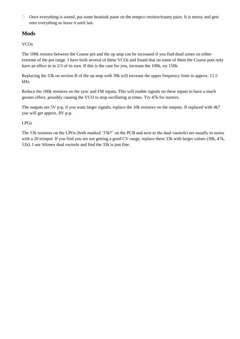
Once everything is sorted, put some heatsink paste on the tempco resistor/tranny pairs. It is messy and gets
onto everything so leave it until last.
Mods
VCOs
The 100k resistor between the Coarse pot and the op amp can be increased if you find dead zones on either
extreme of the pot range. I have built several of these VCOs and found that on some of them the Coarse pots only
have an effect in in 2/3 of its turn. If this is the case for you, increase the 100k, try 150k.
Replacing the 33k on section B of the op amp with 39k will increase the upper frequency limit to approx. 11.5
kHz.
Reduce the 100k resistors on the sync and FM inputs. This will enable signals on these inputs to have a much
greater effect, possibly causing the VCO to stop oscillating at times. Try 47k for starters.
The outputs are 5V p-p, if you want larger signals; replace the 10k resistors on the outputs. If replaced with 4k7
you will get approx. 8V p-p.
LPGs
The 33k resistors on the LPGs (both marked ‘33k*’ on the PCB and next to the dual vactrols) are usually in series
with a 20 trimpot. If you find you are not getting a good CV range, replace these 33k with larger values (39k, 47k,
51k). I use Silonex dual vactrols and find the 33k is just fine.
Fixes
LPGs
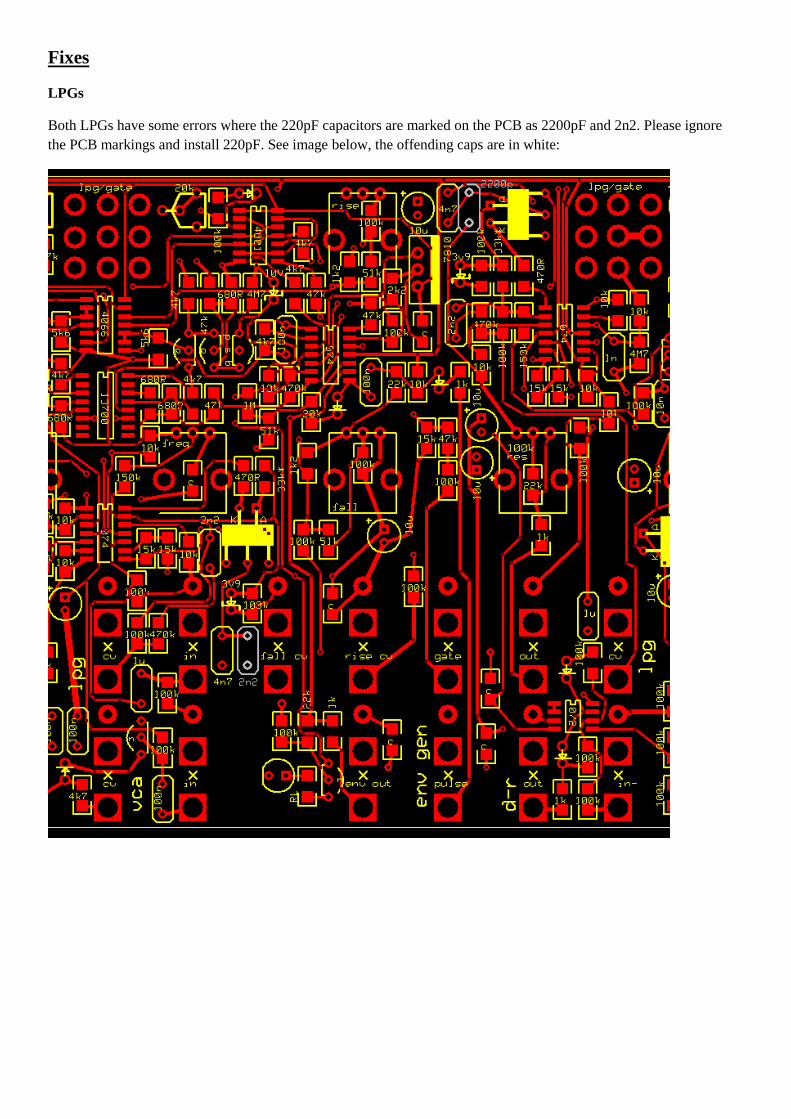
Both LPGs have some errors where the 220pF capacitors are marked on the PCB as 2200pF and 2n2. Please ignore
the PCB markings and install 220pF. See image below, the offending caps are in white:
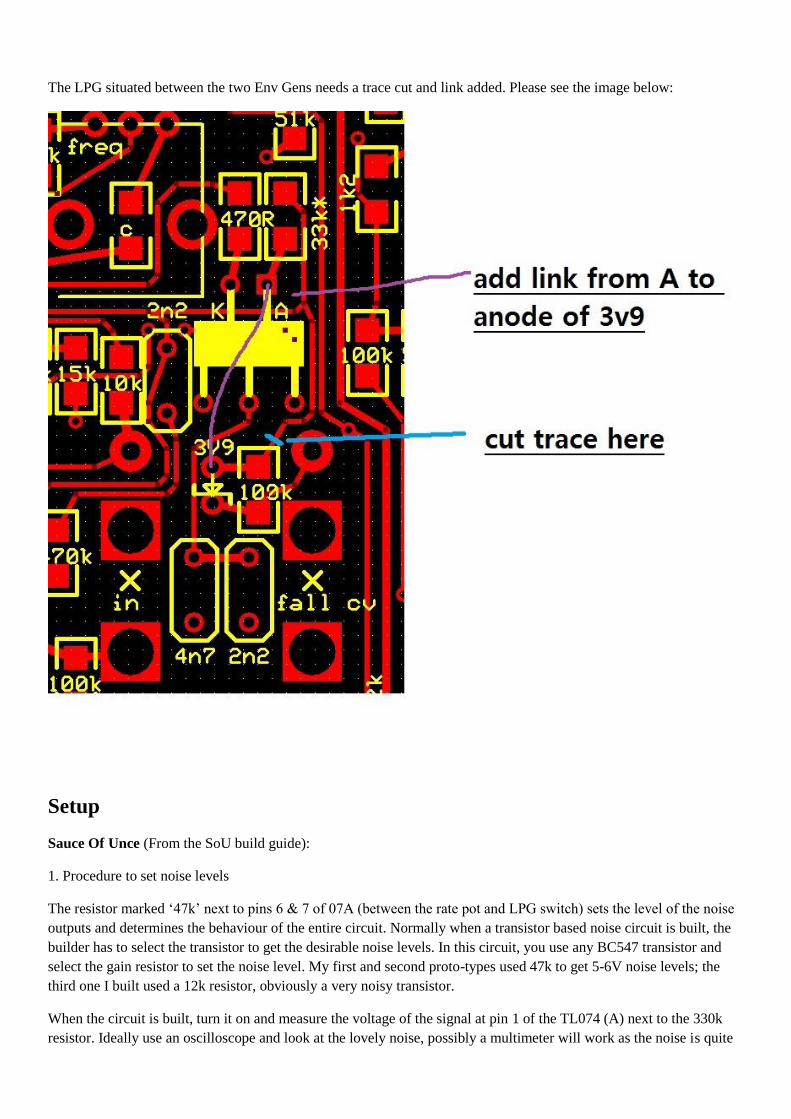
The LPG situated between the two Env Gens needs a trace cut and link added. Please see the image below:
Setup
Sauce Of Unce (From the SoU build guide):
1. Procedure to set noise levels
The resistor marked ‘47k’ next to pins 6 & 7 of 07A (between the rate pot and LPG switch) sets the level of the noise
outputs and determines the behaviour of the entire circuit. Normally when a transistor based noise circuit is built, the
builder has to select the transistor to get the desirable noise levels. In this circuit, you use any BC547 transistor and
select the gain resistor to set the noise level. My first and second proto-types used 47k to get 5-6V noise levels; the
third one I built used a 12k resistor, obviously a very noisy transistor.
When the circuit is built, turn it on and measure the voltage of the signal at pin 1 of the TL074 (A) next to the 330k
resistor. Ideally use an oscilloscope and look at the lovely noise, possibly a multimeter will work as the noise is quite
solid and may look like DC. You can expect get a voltage of 0.2 to 1.2V. Whatever you get, assuming you want noise
levels of 5-6V, use this equation to determine the resistor:
11000/(your voltage at pin 1)=resistor Ω
Just choose a resistor the next standard value up from your answer.
So, for example, if you measure 0.25V at pin 1 of TL074 (A), you would calculate 11000/0.25 = 44000, so use a 47k
resistor
If you measure 1V at pin 1, you would calculate 11000/1 = 11000, so use a 12k resistor.
It doesn’t have to be exact, near enough is good enough.
2. There are three test points, useful for troubleshooting, marked T1, T2, T3. You need an oscilloscope to test them.
T1 should be a random noise signal, approx 5V amplitude. A bit bigger or smaller is okay.
T2 should be a ‘noisy’ or jittery sawtooth, about 8V amplitude, around 100Hz. It does not have to be exactly these
values, near enough is fine.
T3 is the output of the VCO, should be a square-wave bouncing from approx +10V to -10V and changing frequency
as you tweak the Random pot. The frequency should go from very slow (say every 20 seconds) to 30Hz. Again these
values do not need to be exact, the frequency range will depend a lot on your single vactrol. I have seen some get up to
50Hz and others down to 1 minute per cycle.
VCOs
The 100k trimpots are used to set up the range of the Coarse tune pots. Listening to, or monitoring on a ‘scope, the
output, adjust the 100k trimpot until you can get full range from the coarse pot, expect from 15-20Hz up to 9.5k Hz (or
11.5k Hz with 39k mod).
The 20k trimpots are used to get 1V/oct tuning. Usually this is done with the pots disconnected, but difficult in this
case. You want to see an 18mV increase on the node between the 56k resistor and the 1k tempco for every 1V increase
in the CV signal coming in. If you don’t care much about 1V/oct, just set it in about the middle.
VC Reverb
The drive trimpot sets the gain of the signal going into the tank; adjust so the output signal is not too quiet and not
distorted.
The wet and dry gain trimpots are used to set the wet and dry signal levels so they respond to incoming CVs as you
like. The wet & dry balance trimpots are to balance the OTAs and remove any clicking or thumping from CVs.
If you find the wet or dry signals are still too low, you can reduce the values of the 100k resistors feeding these signals
into the MIX OUT op amp stage.

DIF-RECT (only Vout + used and just 1 In- and 1 In+)