Embed Size (px)
Citation preview
- 1 -
ENGINEERING SERVICES AGREEMENT
for the
DESIGN AND CONSTRUCTION INSPECTION OF THE
CELL 3 DISPOSAL AREA
between
DELAWARE SOLID WASTE AUTHORITY
and
GEOSYNTEC CONSULTANTS
CONTRACT DSWA-288
THIS AGREEMENT, made and entered into as of this ____ day of ________,
1994, between Delaware Solid Waste Authority (AUTHORITY) and GeoSyntec
Consultants (ENGINEER), a Florida corporation.
ARTICLE I. DESCRIPTION OF THE PROJECT
The project encompasses the AUTHORITY‘s plans to design, construct, and
operate a new landfill disposal area (approximately twenty-four (24) acres in size) at the
Southern Solid Waste Management Center (SSWMC) which shall be known as “Cell
3”. The Cell 3 Disposal Area shall overlap and be operated concurrently with the
previous disposal area, Cell 2. The Cell 3 Disposal Area shall be divided into
independent subcells, each having a separate drainage system. The Facility design shall
include pertinent environmental, ecological, engineering, and economic considerations
for the operation of a sanitary landfill facility (Facility) in full compliance with all
applicable laws and regulations. The site shall be surveyed and its characteristics
ascertained and evaluated for sanitary landfill construction and operation with the
necessary design and permit data generated. The Facility shall be designed on a cost-
effective basis, and in a timely manner. All design work for Cell 3 and other necessary
materials required for the Authority
- 2 -
to make permit submissions to the Delaware Department of Natural Resources and
Environmental Control (DNREC) and other appropriate regulatory agencies. The
submission of the 100% draft solid waste permit application to DNREC shall be
completed by December 1, 1994.
Construction inspection services for the disposal area shall be provided by the
ENGINEER as the AUTHORITY‘s representative to protect the AUTHORITY against
defects and deficiencies in the work of the construction contractor and to monitor the
contractor‘s compliance with an April 1, 1996 completion date for the first subcell for
Cell 3 and September 2, 1996 as the final completion date for the entire Cell 3 Disposal
Area in accordance with the schedule shown in Exhibit A.
ARTICLE II. SERVICES TO BE PERFORMED BY ENGINEER
A. The ENGINEER agrees to perform engineering and construction
inspection services for the AUTHORITY on the Project as an independent contractor as
set forth in EXHIBIT B, which is attached hereto and incorporated by reference (the
Services).
B. The ENGINEER promptly after execution of the Agreement shall advise
the AUTHORITY, in writing, of the person designated as Project Manager. Such
designation and any replacement thereof shall be subject to the approval of the
AUTHORITY.
C. The period of performance for this contract shall be in accordance with
the schedule shown in Exhibit A.
ARTICLE III. DRAWINGS, PLANS AND SPECIFICATIONS
All final data, reproducible drawings, plans, specifications and reports,
developed by the ENGINEER under the Agreement, shall
- 3 -
belong to the AUTHORITY, but the ENGINEER may retain copies thereof. The
AUTHORITY shall make representation to the Engineer that any information
developed under this agreement if provided to a third party, it shall be with the
understanding that said information was obtained by the AUTHORITY for expressed
purposes stated in this Agreement or directly related thereto. The ENGINEER shall
assume no responsibility for any use for purposes not related or indirectly related to
those expressed in this Agreement.
ARTICLE IV. CONFIDENTIALITY
The ENGINEER agrees that any reports, information, maps, data or other forms
of recorded information identified as confidential by the AUTHORITY and given to or
prepared or assembled by the ENGINEER and its subcontractors in the completion of
this work shall be kept confidential for a period of five (5) years from the date of
completion of the work and shall not be made available to or reproduced for any
individual or organization without the prior written approval of the AUTHORITY;
provided however, that this obligation of confidentiality shall not extend to information
which was previously known to the ENGINEER prior to being received from the
AUTHORITY or which is now or becomes information in the public domain, or which
is independently received by the ENGINEER from a third party having no obligation of
confidentiality to the AUTHORITY or which is required to be disclosed as a result of a
court order.
ARTICLE V. ACCOUNTING OF COSTS
The ENGINEER shall maintain books, records, documents,
- 4 -
accounts and other evidence of costs in accordance with generally accepted accounting
principles and practices consistently applied. The AUTHORITY or its designee, during
the ENGINEER‘s normal business hours, shall have access to such books, records,
documents, accounts and other evidences for the purpose of inspection, auditing and
copying. The ENGINEER shall preserve and shall make such books, records,
documents, accounts and other evidences available to the AUTHORITY or its designee
at no charge for a period of three (3) years upon the completion of Services under this
Agreement. Notwithstanding anything to the contrary stated herein, the AUTHORITY
shall have the right to inspect, audit and copy the books, records, documents, accounts
and other evidence pertaining to contract costs as set forth in EXHIBIT C (Tables 1-24)
and EXHIBIT D.
ARTICLE VI. PROFESSIONAL AUTHORIZATION
The ENGINEER hereby represents that it and all of its engineering
subcontractors have and will maintain for the duration of the Agreement a Certificate of
Authorization to Practice Engineering in the State of Delaware as required by Chapter
28, Title 24 of the Delaware Code (rev. 1974), as now constituted and as may be
amended from time to time and that all final engineering reports, plans and drawings
shall be sealed by a professional engineer licensed in Delaware. The ENGINEER
further represents that any professional land surveying work performed under this
Agreement shall be conducted by a professional land surveyor licensed under the
provisions of Chapter 27 of Title 24 of the
- 5 -
Delaware Code as now constituted and as may be amended from time to time or
conducted by a professional engineer and that all survey plots shall bear the seal of said
licensed professional land surveyor or professional engineer. The ENGINEER further
represents that any subsurface exploration work shall be supervised by, and all drawings
and documents resulting therefrom shall be prepared and certified by a professional
geologist licensed under the provisions of Chapter 36 of Title 24 of the Delaware Code
or a professional engineer.
ARTICLE VII. MISCELLANEOUS PROVISIONS
A. In the event that any of the provisions, or portions, or applications
thereof, of this Agreement are made unenforceable or invalid by any existing or
subsequent federal, state or local requirements, either statutory or administrative, or are
held to be unenforceable or invalid by any Court of competent jurisdiction, the
AUTHORITY and the ENGINEER shall, except as provided otherwise hereinafter,
negotiate an adjustment in the affected provisions of the Agreement with a view toward
effecting the purposes of this Agreement, and the validity and enforceability of the
remaining provisions or portions, or applications thereof shall not be affected thereby.
B. The AUTHORITY and the ENGINEER agrees to comply with all
applicable federal, state and local requirements, either statutory or administrative
applicable to the performance of services under the Agreement, which are either now in
effect or hereinafter enacted and, if necessary, to execute and deliver any amendment to
- 6 -
this Agreement, in order to meet any said new requirements.
C. Each and every provision of law required by Federal or state law,
statutory or administrative, or required by third parties to be inserted in the Agreement
for purposes of grant funding, shall be inserted in the Agreement and in such event the
parties hereto agree to renegotiate the terms and conditions thereby affected, it being the
intention to preserve the terms and conditions as set forth herein.
D. The titles of the articles of this Agreement are inserted for convenience
or reference only and shall be disregarded in construing or interpreting any of its
provisions.
E. This Agreement and any written amendment thereto constitutes the entire
Agreement and understanding between the AUTHORITY and the ENGINEER and
there are no other terms, obligations, covenants, representations, or statements, oral or
otherwise, or any kind whatsoever.
F. This Agreement shall be binding upon and inure to the benefit of the
parties hereto, and their respective legal representatives successors and assigns,
including any public body which will succeed to or have assigned to it any of the
functions of the AUTHORITY with respect to this Agreement, and any reference to the
AUTHORITY and the ENGINEER shall include reference to their respective
successors, assigns and nominees provided however, that the ENGINEER may not
transfer, assign, delegate or subcontract its obligations under this Agreement without the
express written consent of the AUTHORITY. Without limiting the foregoing, the
- 7 -
AUTHORITY shall have the right to reject any assignee, delegatee, or subcontractor
proposed by the ENGINEER on the basis of the cost of the services to be performed.
The ENGINEER hereby guarantees to the AUTHORITY compliance by any assignee,
delegatee, or subcontractor with responsibilities and liabilities herein assumed by the
ENGINEER. The ENGINEER agrees that the AUTHORITY will incur no duplication
of costs as a result of any subcontract. Subcontractors will be utilized to meet the
various requirements of the project and as need dictates. Based on the present scope of
work, the following subcontractors are anticipated to be used on this project:
Subcontract
Greenhorne and O‘Mara, Inc. – (surveying, access road, miscellaneous design)
Ross Murphy Finkelstein, Inc. – (electrical)
A.C. Schultes of Delaware, Inc. – (drilling)
Design – Dr. Fred Pohland, P.E. (leachate collection, leachate recirculation, and
landfill gas management system)
The ENGINEER shall provide written documentation and obtain the AUTHORITY‘s
written approval prior to subcontracting any elements of the work included in this
agreement. A description of the work to be performed by the subcontractor and an
estimate of the cost for such services will be included in the request for subcontractor
approval. Payment for subcontractors shall not exceed the ENGINEER‘s budget
amount as specified in Exhibit C (Tables 1-24).
- 8 -
G. This Agreement, in all respects, shall be governed by, and shall be
construed, interpreted and/or enforced in accordance with the laws of the State of
Delaware. The State Courts of Delaware shall have exclusive jurisdiction over this
Agreement and the parties thereto with respect to any and all disputes arising therefrom
or relating thereto.
H. The ability of the AUTHORITY to terminate this Agreement as provided
herein shall in no way affect the AUTHORITY‘s right to proceed with litigation against
the ENGINEER, without exercising such right to terminate.
ARTICLE VIII. INSURANCE
During the term of this Agreement, the ENGINEER and each of its
subcontractors shall maintain the following insurance in at least the minimum amounts
specified:
A. Workman‘s Compensation and Employer‘s Liability Insurance applying
to the ENGINEER‘s employees as required by law.
B. Automobile Bodily Injury and Property Damage Liability Insurance
covering automobiles owned or hired by the ENGINEER, with $1,000,000 combined
single limit (Bodily Injury and Property Damage):
C. Professional liability (errors and omissions) coverage in the amount of
$2,000,000 combined single limit. (The ENGINEER‘s subcontractors shall maintain
coverage in an amount of at least their contract amount with the ENGINEER for this
project.)
D. General Liability insurance coverage in the amount of $1,000,000 each
occurrence (Bodily Injury and Property Damage),
- 9 -
$2,000,000 general aggregate limit (other than products and completed operations)
$2,000,000 products and completed operations aggregate and $1,000,000 each
occurrence personal injury.
E. Such other insurance as may be mutually agreed upon. The ENGINEER,
with respect to the insurance specified herein by Subparagraph B and D, shall designate
the AUTHORITY as an additional insured for liability resulting from negligence
attributable to the ENGINEER under said policies with the loss payable provisions
jointly benefiting the ENGINEER and the AUTHORITY as their respective interest
may appear and that the AUTHORITY‘s right to collect for a loss shall not be
invalidated due to any act of the ENGINEER. Within thirty (30) days following the
signing of the Agreement, the ENGINEER shall furnish to the AUTHORITY
satisfactory evidence that the foregoing insurances are in effect. The AUTHORITY
shall be notified in writing thirty (30) days prior to the cancellation or material change
of coverage, as the evidence of insurance shall so specify.
ARTICLE IX. FORCE MAJEURE
Neither party hereto shall be considered in default in the performance of its
obligations hereunder to the extent the performance of any such obligation is prevented
or delayed by any cause, existing or future, which is beyond the reasonable control of
the affected party.
ARTICLE X. NOTICES
Any notices required or permitted by this Agreement to be given by the
ENGINEER to the AUTHORITY shall be in writing and
- 10 -
shall be addressed to:
Delaware Solid Waste AuthorityPost Office Box 455
Dover, Delaware 19903-0455
ATTENTION: Ann Marie AndrzejewskiProject Engineer
or such address as the AUTHORITY may from time to time designate to the
ENGINEER in writing. Any notice required or permitted by this Agreement to be given
by the AUTHORITY to the ENGINEER shall be in writing and shall be addressed to:
GeoSyntec Consultants5950 Symphony Woods Road
Suite 510Columbia, MD 21044
Attn: Michael F. Houlihan, P.E.
Any such notice shall be delivered by hand or sent by certified mail, return receipt
requested and shall deemed to have been given on the day of its receipt at the address to
which such notice is as directed regardless of any other date that may appear thereon.
ARTICLE XI. COMPENSATION
The AUTHORITY shall pay the ENGINEER for its Services hereunder on a
cost reimbursement basis as defined in EXHIBIT C (Tables 1-24) of this Contract in an
amount not to exceed $698,829.03.
ARTICLE XII. MANNER AND TIME OF PAYMENT
The AUTHORITY shall pay the ENGINEER in the manner and at the time set
forth in EXHIBIT D attached hereto and made a part hereof.
ARTICLE XIII. TERMINATION FOR CONVENIENCE
Anything contained in this Agreement to the contrary notwithstanding,
- 11 -
the AUTHORITY shall have the right, at any time and for any reason notwithstanding
the absence of any breach or default on the part of the ENGINEER to terminate this
Agreement upon fifteen (15) days written notice to the ENGINEER. In the event of
such termination, the AUTHORITY shall pay the ENGINEER in accordance with the
provisions of this Agreement for and only for those services performed prior to the
effective date of such termination and the reasonable cost of termination. Any such
termination of the Agreement by the AUTHORITY shall not operate to terminate the
ENGINEER’s liabilities set forth in this Agreement for Services performed prior to
termination.
ARTICLE XIV. TERMINATION FOR DEFAULT
In addition to its rights and options, to be exercised at its discretion voluntarily
to terminate this Agreement in accordance with ARTICLE XIII, the AUTHORITY shall
also have the right to terminate this Agreement if at any time:
A. The ENGINEER shall abandon its duties or obligations hereunder for a
period of fifteen (15) days; or
B. The ENGINEER shall fail to observe or perform any obligation or duty
to be observed or performed by it hereunder and either (1) work to cure a breach or
default is not commenced within fifteen (15) days after receipt by the ENGINEER of
written notice from the AUTHORITY to cure such breach or default; or (2) such work
to cure breach or default is not completed within thirty (30) days of commencement of
such work; or (3) the breach or default is such that it cannot be cured by the
ENGINEER within a period of thirty
- 12 -
(30) days from and after the date of commencement of work to cure such breach or
default, any of which of above events, the AUTHORITY, at its sole option without
prejudice to any other right or remedy, after giving the ENGINEER five (5) days
written notice, may terminate this Agreement.
ARTICLE XV. NOTICE OF COMPLETION
Upon completion of the services, the ENGINEER shall, and upon completion of
any independent identifiable portion of the Services, the ENGINEER may, notify the
AUTHORITY in writing of the date of said completion. The Services referred to in
said notice shall be deemed, for purposes of administering this Agreement, to have been
completed on the date indicated in said notice providing said notice is received by the
Authority within seven (7) days from the date indicated in said notice, unless within
thirty (30) days of receipt of said notice, the AUTHORITY provides the ENGINEER
with a written listing of Services not completed; provided however, that the purpose of
this provision is to assist in the efficient administration of the Agreement and this
provision shall not act or be construed or interpreted as a waiver of any rights the
AUTHORITY may have with respect to liability assumed by or imposed upon the
ENGINEER under this Agreement. The ENGINEER shall complete any services listed
by the AUTHORITY as incomplete and the notice of completion procedures shall be
repeated.
ARTICLE XVI. LIABILITY OF ENGINEER
Except as specifically provided herein, the ENGINEER’s sole liability to the
AUTHORITY (whether the claims by the AUTHORITY are
- 13 -
alleged to have arisen from the negligence of the ENGINEER, its subcontractors, agents
or employees, breach of warranty, breach of contract, strict liability and/or any other
cause) shall be for direct damages and, without modifying the meaning of direct
damages, for damages to real and personal property resulting from the ordinary
negligence of the ENGINEER, its subcontractors, agents or employees or breach of
contract, not to exceed a total amount for all claims by the AUTHORITY against the
ENGINEER of Two Million Dollars ($2,000,000); provided however, that nothing
contained herein shall limit or restrict the ENGINEER’s liability for intentionally
wrongful, fraudulent or grossly negligent conduct. Where reperformance of Services
will fully remedy any errors or omissions of the ENGINEER, the ENGINEER may
reperform such Services at its own expense in a timely fashion, provided that any
reperformance shall be commenced within fifteen (15) days of learning of such errors or
omissions and shall be completed within reasonable period of time not exceeding thirty
(30) days. Any reperformance of Services shall not reduce of affect the ENGINEER’s
maximum liability under this Agreement. The ENGINEER warrants that it shall
perform its Services in accordance with the standards by which similar professional
engineers and project management firms perform services of a similar nature, This
warranty is in lieu of and excludes all other warranties from the ENGINEER to the
AUTHORITY, whether express or implied by operation of law or otherwise, including
any warranty of fitness for a particular purpose between the ENGINEER and the
AUTHORITY.
- 14 -
IN WITNESS WHEREOF the parties hereto through their respective
undersigned authorized representatives intending to be bound thereby on this ..1st…day
of ..June…, 1994, have executed this Agreement
IN THE PRESENCE OF:
WITNESS
TRACIE CROWE___________________NAME TYPED OR LEGIBLY WRITTEN
GEOSYNTEC CONSULTANTS
BY_____________________________
RUDOLPH BONAPARTE__________NAME TYPED OR LEGIBLY WRITTEN
_____________________________________WITNESS
ALISON SANTILLO as to R. BonaparteNAME TYPED OR LEGIBLY WRITTEN
TITLE Chief Operating Officer__
DELAWARE SOLID WASTE AUTHORITY
WITNESSBY _______________________________NAME TYPED OR LEGIBLY WRITTEN
Libby J. Kelley________________NAME TYPED OR LEGIBLY WRITTEN
Pasquale S Canzano_____________NAME TYPED OR LEGIBLY WRITTEN
TITLE Chief Operating Officer___
PER AUTHORITY RESOLUTION DATED May 26, 1994
EXHIBIT A
PROJECT SCHEDULE
EXHIBIT B
SERVICES TO BE PERFORMED BY
GEOSYNTEC CONSULTANTS
B - 1
EXHIBIT B
SERVICES TO BE PERFORMED BY
GEOSYNTEC CONSULTANTS
GeoSyntec Consultants (ENGINEER) shall provide engineering and constructioninspection services to the AUTHORITY for the project which shall generally consist of:
A. Site Studies
1. Survey of the Cell 3 Disposal Area including all areas needed forCell 3 support facilities as well as a survey of all areas delineated aswetlands.
2. Detailed Hydrogeological and Geotechnical Investigation and Reportfor the Cell 3 Disposal Area.
3. Access Road Study and Report which includes an evaluation of thecondition of the existing access road with a recommendation as tothe best method of repair (example: patching, reconstruction,rotomill, and overlay).
4. Other DNREC site study requirements as stated in the DRGSW.
B. Design Work
Detailed design of the entire Cell 3 Disposal Area with 3 independentsubcells approximately eight (8) acres each. The design shall include,but not be limited to:
1. double liner system2. leachate collection and storage system3. leachate recirculation system4. design of a leak detection system5. evaluation of current liner technologies6. design of a passive landfill gas collection and odor control system7. design of a stormwater control system8. design of the cap for cell 39. improvements to existing paved access road
C. Preparation of Operations and Maintenance Manual
The ENGINEER shall prepare manuals detailing the procedures for theoperation and maintenance of the Cell 3 Disposal Area, the leakdetection system, the areas of wetland mitigation (as provided by theAUTHORITY), and
B - 2
operation of the leachate storage tanks and the recycling system.
D. Construction Inspection and General Services
1. Preparation of Bid Documents for the Cell 3 Disposal Area:
§ Preparation of separate Bid Documents for the construction andoperation of Cell 3.
2. Evaluate Bids and Make Recommendations:
§ Evaluate Bids and make recommendations for both theconstruction and operation of Cell 3.
3. Resident Inspection and Other Services:
§ Resident inspection and other services for the construction of theCell 3 Disposal Area.
§ E. Preparation of As-built Drawings
The ENGINEER and the AUTHORITY understand that, from time to time, it
may be necessary or desirable for the AUTHORITY to assign to the ENGINEER
various tasks within the general scope of services which are not set forth below and
accordingly, the AUTHORITY by written order may assign such tasks. Such additional
assignments, as with all tasks except as more specifically provided, shall be performed
within a reasonable period of time in light of the demands of the project and the
ENGINEER shall, on request of the AUTHORITY, provide in advance of assignment a
reasonable estimate of the cost of performance. The ENGINEER and the
AUTHORITY also recognize that, from time to time, it may be necessary or desirable
to reduce the scope of the services set forth below, and accordingly, the AUTHORITY
may by written notice reduce the scope of the services. Assignments which are outside
of the work scope of this Agreement shall require a written amendment, mutually
agreed upon by the AUTHORITY and ENGINEER. Prior to approval of said
amendment by the AUTHORITY’s Board of Directors, the ENGINEER shall have no
obligation to comply with nor shall the AUTHORITY be obligated to approve payment
for services under said Agreement.
PROJECT ELEMENT 1 – SITE STUDIES
PROJECT ELEMENT 1A – SURVEYS
All Survey work shall be performed under the supervision of a surveyor or
engineer registered in the State of Delaware.
B - 3
The ENGINEER shall provide the following surveying services:
1. Topographical survey of the proposed site location.
2. Conduct a survey for the sites as required to complete the design andconstruction of the Cell 3 Disposal Area including the proposed landfill area,separation berms, access roads, the repaving / improvements of the entranceroad to the SSWMC, the area(s) proposed for the leachate storage, stormwatersedimentation basin(s) and other appurtenances.
3. Provide surveying to establish a construction base line and control points forthe site based on Delaware State Plan Coordinate System and NationalGeodetic Vertical Datum.
4. Provide surveying to identify the vertical and horizontal location of any newtest pits, borings, and monitoring wells or other instrumentation installed toobtain hydrogeologic or geotechnical information.
5. Survey flagged wetlands locations for delineation of wetland boundaries.
All topographic surveys for the Cell 3 Disposal Area shall be at a scale of 1”=50’with 1’ contour intervals.
PROJECT ELEMENT 1B – HYDROGEOLOGICAL AND GEOTECHNICALINVESTIGATION
The primary purposes of the hydrogeologic and geotechnical investigation willbe:
1. To determine the geotechnical properties which may affect the design andconstruction of the proposed landfill expansion.
2. To determine the hydrogeologic characteristics of the site. This is necessary todetermine the quality of the existing groundwater, the location of the aquifers andconfining layers, and the treatments necessary to prevent contamination of thegroundwater.
3. To provide the necessary information for the facility design and requirements ofDNREC.
The ENGINEER shall prepare a drawing depicting the designated locations foradditional test-pits, soil test borings, piezometers, monitoring wells, and othersubsurface exploration work required at the site. At least one meeting shall be requiredwith the AUTHORITY and one with the AUTHORITY and DNREC personnel for
B - 4
authorization of the proposed hydrogeological and geotechnical investigation.
All work shall be completed under the direct supervision of a geologistregistered in the State of Delaware.
DETAILED GEOTECHNICAL INVESTIGATION
Any information supplied by the AUTHORITY to the ENGINEER has beenobtained as part of other work. The AUTHORITY assumes no responsibility for itsaccuracy of for any interpretations that the ENGINEER may make therefrom.
The scope of the geotechnical investigation for Cell 3 shall consist of thecomponents listed below. The ENGINEER shall use the existing data base as well asnew information from the proposed investigation to:
1. Classify the existing soils in the area designated to the expansion for theirsuitability for use as a sub-base material.
2. Determine the estimated subgrade settlements under the anticipated loadings(final landfill grades) from the integration of Cell 1 and Cell 2. Thesesettlements will be used to design the leachate collection system andestablish the final bottom grades of the base of the landfill.
3. Determine if any soil strengthening requirements will be necessary.
4. Determine any other critical components not listed.
The objective of the geotechnical investigation is to integrate the above analysisto determine the maximum allowable height of the landfill while accounting for anadequate factor of safety for the berm/subgrade stability, and development of thelandfill using projected incoming tonnage rates.
SUBSURFACE INVESTIGATION
A minimum of 5 test pits shall be excavated across the proposed Cell 3 areaunless the AUTHORITY deems that less than 5 test pits provides an adequaterepresentation of the nature and horizontal and vertical extent of the different soilmaterials in the proposed disposal area footprint.
Soil borings shall be advanced to characterize the subsurface soils for settlementand stability analyses. A minimum of one deep boring will be advanced within thefootprint of Cell 3 to collect undisturbed samples of fine-grain soils. In addition, aminimum of
B - 5
one shallow boring shall be advanced in the vicinity of the proposed leachate storagetank area for characterization of those soils (i.e., grain size, Atterberg limit, standardProctor compaction, and moisture content testing).
DETAILED HYDROGEOLOGIC INVESTIGATION
The ENGINEER shall review existing data for permit and design purposes. Anyinformation supplied by the AUTHORITY to the ENGINEER has been obtained as partof other work. The AUTHORITY assumes no responsibility for its accuracy or for anyinterpretation or deductions that the ENGINEER may make therefrom.
SUBSURFACE INVESTIGATION
The initial task in the hydrogeological study is to evaluate the efficiency of theexisting groundwater monitoring network.
The ENGINEER shall install a minimum of four (4) shallow monitoring wells(20-ft deep) adjacent to the proposed Cell 3 Disposal Area, roughly at the four cornersof the disposal area unless it is determined that less than 4 wells are sufficient toeffectively evaluate the current efficiency of the groundwater monitoring network. TheENGINEER shall identify the parameters required for the sampling and analysis of thenew monitoring wells. The AUTHORITY’s existing environmental monitoringcontractor shall be responsible for the sampling and analysis of these parameters duringthe scheduled period as identified in the Project Schedule in EXHIBIT A.
The ENGINEER’s hydrogeological investigation program shall quantify thegroundwater component of measurable stream flow in the Beaverdam Branch due to arequirement under the newly-promulgated DRGSW for potential monitoring of surfacewater into which groundwater flowing from beneath a landfill discharges. Apreliminary evaluation shall be made prior to the October 1994 sampling date so that asurface-water sample could be collected if necessary.
In order to monitor vertical head gradients along the Beaverdam Branch, theENGINEER shall install a cluster piezometer at three depth intervals within theuppermost aquifer. After the initial installation and development, the AUTHORITYshall be responsible for the monitoring of the stream flow along the drainage channel ofthe Beverdam Branch.
Drilling and piezometer construction methods shall be consistent with previoussite explorations and comply with applicable industry and state standards.
At a minimum, water-level measurements shall be made during the routinequarterly groundwater monitoring by the AUTHORITY, and
B - 6
may be increased in frequency to bi-monthly or monthly, depending upon the
anticipated degree of seasonal water level fluctuations.
The well boreholes shall be drilled by A.C. Shultes, of Seaford, DE. Acontinuous observation log of soil lithologies from drill cuttings shall be made by the
ENGINEER’s field geologist/engineer. Well materials and completion techniques shall
be consistent with previous monitoring well installations.
Following completion of the well installation, the ENGINEER shall supervise
the development of each monitoring well and piezometers, if required, as performed by
the drilling contractor. Wells shall be purged and pumped until stable readings of pH,temperature, and conductivity are obtained and water clarity stabilizes.
Testing shall be performed to measure the hydraulic conductivity of the aquifer
following well development. If during final stages of well development, pumping at astable pumping rate can be maintained and drawdown stabilizes in he well, the water-
level recovery response after pumping will be stopped and groundwater recovery will be
measured. Data from this test may be used to calculate the parameters of transmissivity/ hydraulic conductivity and aquifer storage. An alternative method, which may be used
if a stable pumping rate cannot be obtained, is a rising and/or falling head (slug) test.
The ENGINEER shall update the existing sample and analysis plan to includethe new monitoring wells, and surface-water sampling location if necessary. In
addition, the updated DRGSW pose new requirements for sample parameters, data
evaluation, and reporting which shall be included in the plan revision.
HYDROGEOLOGICAL AND GEOTECHNICAL REPORT
The ENGINEER shall analyze the data from previous site explorations and the
proposed Cell 3 Disposal Area exploration and prepare a detailed hydrogeological andgeotechnical report for submittal with the permit application. The report will contain, at
a minimum:
1. description of underlying soil conditions at the site and their suitability foruse as a sub-base and construction material; recommendations to design
constraints and/or soil strengthening requirements will be included;
2. maps depicting site groundwater flow conditions for each aquifer, and pointsof groundwater discharge;
3. geologic cross-section maps along critical groundwater flow paths;
B - 7
4. potentiometric surface map for the surficial aquifer estimated seasonal highwater table;
5. description of the characteristics of the aquifers and their potential forpollution by the proposed Cell 3 Disposal Area;
6. vertical and horizontal location of new test pits, borings, and/or monitoringwells with respect to the local site control plan;
7. description of present groundwater quality and comparison to historical data;
8. map depicting the presence of wetlands and/or subaqueous lands for the Cell3 Disposal Area only; and
9. any other critical parameters or aspects not previously mentioned.
Five (5) copies of the draft report shall be prepared and submitted to theAUTHORITY for review and comment. A meeting shall be held with theAUTHORITY to discuss the draft report. Revisions shall be made as necessary, andseven (7) copies shall then be submitted to the AUTHORITY for presentation toDNREC.
The ENGINEER shall then meet with DNREC to answer questions and define ifany additional data may be required. DNREC’s comments shall be reviewed, questionsanswered, and additional data provided if required by DNREC. Ten (10) copies of theFinal Report, signed and sealed by a Delaware Registered Geologist, shall be presentedto the AUTHORITY for internal and external distribution.
PROJECT ELEMENT 1C – ACCESS ROAD STUDY AND REPORT
The ENGINEER shall evaluate the condition of the existing access road with arecommendation as to the best method of repair (i.e. patching, reconstruction, rotomill,and overlay, etc.). The ENGINEER shall contact the AUTHORITY as to theevaluation/recommendations and upon approval incorporate any changes into a writtenreport and the design. Five (5) copies of the draft report shall be presented to theAUTHORITY for review and comment. Revisions shall be made by the ENGINEER asnecessary and ten (10) copies of the final Access Road Report shall be submitted to theAUTHORITY for internal and external distribution.
PROJECT ELEMENT 2 – DETAILED DESIGN
All design work shall fully comply with all applicable laws and regulations and,in particular, the Delaware Department of Natural Resources and EnvironmentalControl’s Regulations Governing
B - 8
Solid Waste (DRGSW), and the requirements of the current Solid Waste Permits for theSSWMC, Number SW-93/07 (revised).
The ENGINEER shall develop the engineering plans for construction,specifications, operations plan, and other materials necessary to apply to the Departmentof Natural Resources and Environmental control (DNREC) and other authorities for therequired construction permits for the projects described in this Contract. All such plansshall be sealed by a Delaware Registered Professional Engineer. It is anticipated that nomore than two permit submissions and three meetings with the Solid Waste Branch ofDNREC will be required. In addition, two permit submissions and two meetings mayalso be required with each of the following divisions of DNREC; Air Section forlandfill gas, and the Water Resources Section for stormwater control. Such submissionsare envisioned to be an initial submission and follow-up response answering questionsraised by DNREC and/or providing additional information required by DNREC. It isanticipated that one predesign meeting with the Solid Waste Branch of DNREC will benecessary to establish the criteria for designing, operating, and constructing the projectsrelating to the Cell 3 Disposal Area.
The ENGINEER shall establish, subject to review by the AUTHORITY, thecriteria to be utilized for the design of the Cell 3 Disposal Area (approximately 24acres) including the estimated size of the subcells and the extent of phasing required, theestimated tonnages to be handled, projected life of the site, desired support facilitiesincluding leachate control and design requirements that may be more stringent thanrequired by law. The overall facility design shall include Cell 3 and shall consider theinterface of Cell 2. The ENGINEER shall evaluate the use of alternate constructionmaterials for the construction and capping of Cell 3, in particular, fly ash fromDelmarva Power which could be used as a sub-base.
In addition, the ENGINEER shall provide the AUTHORITY with copies of allAUTOCAD files pertaining to this project. The ENGINEER shall also providecalculations to the AUTHORITY upon request.
The ENGINEER’s efforts shall include, at a minimum, the following work:
1. Liner and drainage system design
2. Sub-base grading for the liner system
3. Settlement and stability analyses
4. Leachate compatibility testing
5. Evaluation of alternative liner materials
6. Study of estimated leachate production rates
7. Leachate storage and collection system
8. Leachate recirculation system
9. Leak detection system
B - 9
10. Development of miscellaneous plans
11. Permitting
12. Landfill gas management system
13. Stormwater management
14. Access road design
15. Capping system
16. Closure plan
The ENGINEER shall submit five (5) copies of a draft design criteria report tothe AUTHORITY for review of the ENGINEER’s conclusions and recommendations.The ENGINEER shall revise the draft report to incorporate the AUTHORITY’scomments and resubmit ten (10) copies of the final report, signed, and sealed by aDelaware registered professional engineer.
PROJECT ELEMENT 2A – LINER SYSTEM
LINER AND DRAINAGE SYSTEM DESIGN
The ENGINEER shall design a double liner system in accordance withDelaware Regulations Governing Solid Waste (DRGSW) §5.C.2.c (2) (b) for the Cell 3Disposal Area. The primary liner shall be a composite liner (i.e. geomembrane lineroverlapping either a natural or geosynthetic clay layer (GCL)). To meet therequirements of DRGSW §5.C.2.c (2) (b) for landfills which recirculate leachate, thesecondary liner must also be a composite liner.
The ENGINEER shall evaluate various synthetic liner materials for use in theliner and drainage systems as alternatives to the materials specified in the DRGSWregulations.
In addition, the ENGINEER shall perform leachate compatibility testing(USEPA 9090 testing) on the geosynthetic components of the composite liner anddrainage systems. The ENGINEER shall also evaluate the following specific aspects:
1. calculation of the anticipated settlement of the landfill cell foundation soils,analysis of stability of the liner system on the slopes and of the waste over theliner system, and analysis of the impact of seismic events on the liner system;
2. calculation of leachate production rates; and
3. calculation of the liner system efficiency and an evaluation of its performance.
At the completion of the analysis, the ENGINEER shall prepare an engineeringreport describing the evaluation of the liner and drainage layer components. The reportshall include recommendations for material selection in addition to results from the9090 testing and the other items listed above. Five (5)
B - 10
copies of the draft report shall be submitted to the AUTHORITY for review andcomment. Revisions shall be made as necessary and seven (7) copies of the report shallbe submitted to DNREC for review and comment. After all revisions have beenincorporated as requested by the Authority and DNREC, the ENGINEER shall submitten (10) copies of the final Liner and Drainage System Design to the AUTHORITY forinternal and external distribution.
SUB-BASE GRADING FOR THE LINER SYSTEM
The sub-base grading plan shall be prepared in a manner that promotes properdrainage of leachate and meets the leachate collection performance requirements ofDRGSW Section 5.2.
The subgrade grading plan shall meet or exceed the DRGSW siting and designrequirements and shall allow for collection of leachate and maintenance of leachatecollection lines as well as accommodate the anticipated settlement of the soilsunderlying the landfill cell. According to DRGSW, the cell must be graded such that:(i) there is a minimum of 5 ft of soil between the bottom of the secondary liner and theseasonal high groundwater level; (ii) the minimum slope on controlling slopes is twopercent; and (iii) the minimum slope on non-controlling slopes is one-half percent. TheENGINEER should interpret the slope requirements to refer to post-settlement slopes.Because of the flat site topography, a significant quantity of material shall be requiredto: (i) maintain the required separation distance between the bottom of the secondaryliner and the seasonal high groundwater level; and (ii) to create the minimum slopesrequired while accounting for the anticipating settlement of the foundation soils.
The subgrade grading plan shall be prepared based on a careful evaluation of theoptimum placement for Cell 3. As stated in the ENGINEER’s proposal, the long-rangeplans for development of the site may be best served by placing Cell 3 along part of thenorth side of Cell 2. The ENGINEER should consider maximizing the airspace of Cell3 by overfilling as much of Cell 2 as possible which may result in a lower developmentcost. Also, innovative grading concepts (such as using fly ash as subgrade fill) shall beconsidered during the subgrade layout process.
SETTLEMENT AND STABILITY ANALYSES
The ENGINEER shall conduct detailed analyses of settlement of the foundationsoils and stability of the liner system at various stages during the life of the landfill,including the impacts to the liner system and the landfill caused by a seismic event. Theanalyses shall be performed using the following information:
1. existing site geologic and geotechnical information;
B - 11
2. information obtained during the Hydrogeological and Geotechnical
Evaluation;
3. strength characteristics of the liner system materials that are recommendedfor use in the liner system and approved by the AUTHORITY; and
4. the anticipated characteristics and geometry of the solid waste that is placed
in the landfill.
The ENGINEER shall perform a series of settlement analyses of the landfill cell
foundation. The results of the analyses shall provide the anticipated total and
differential settlements at several points along the base of the landfill. This informationshall be incorporated into the grading plan so that the minimum slopes described in
DRGSW § 5.C.3.a(3) will be maintained throughout the operational and post-closure
life of the cell (i.e., after settlement has occurred). In the analyses, the ENGINEERshall consider the settlement of all underlying soil (i.e., all soil above bedrock, which is
at a depth of about 5,000 ft below ground) and the impact on settlement of saturated
refuse, which will have a greater weight than dry waste.
The ENGINEER shall analyze the stability of the landfill, including the stability
along potentially weak liner and cover system components, under various loading
scenarios (i.e., on slopes with various heights of waste during critical stages of landfilldevelopment, and for various geosynthetic liner system components).
LEACHATE COMPATIBILITY TESTING
The ENGINEER shall perform the USEPA 9090 tests on the geosyntheticcomponents of the composite liners approved for use by the AUTHORITY. Seven (7)
copies of the U.S. EPA 9090 test results will be transmitted to the AUTHORITY in a
technical memorandum. The AUTHORITY will submit this technical memorandum toDNREC for its approval.
EVALUATION OF ALTERNATIVE LINER AND DRAINAGE
The ENGINEER shall evaluate various geosynthetic materials for use in theliner system as alternatives to the natural materials specified in the DRGSW. The
evaluation shall address geosynthetic alternatives for the following materials:
1. geosynthetic clay liners instead of clay in the composite liners;
2. geonet, or geocomposite drainage layers instead of soil drainage layers;
B - 12
3. geonet or geocomposite drainage swales in the leak detection layer instead ofdrainage pipes; and
4. the use of geosynthetic daily cover materials instead of soil daily materials.
The evaluation criteria shall include, but not be limited to:
1. the material’s performance and its ability to meet or exceed the technicalrequirements of the DRGSW;
2. for the drainage materials, the materials ability to transmit leachate;
3. the cost and availability of the material;
4. the installation cost of the material; and
5. the material’s resistance to leachate.
LEACHATE PRODUCTION RATES
The ENGINEER shall analyze the Cell 3 Disposal Area to estimate the quantityof leachate that will be generated at the site. The analysis shall consider rainfallcharacteristics of the area, the impacts of various types of intermediate, final, and dailycover (including alternate daily covers such as geosynthetic covers, foam covers, andslurry-product covers). Also, the analysis shall be used to help determine the optimumoperating procedures for minimizing the generation of leachate. The leachategeneration analyses shall be performed using the program HELP, published by the U.S.EPA or another AUTHORITY approved computer program. The leachate generationestimates will be used to design the leachate recirculation system and the leachatestorage system.
PROJECT ELEMENT 2B – LEACHATE STORAGE AND COLLECTIONSYSTEM
The ENGINEER shall design the leachate storage and collection system for Cell3. The work of this task shall include design and selection of components for theleachate removal system (i.e. the system to remove leachate from the landfill cells), theleachate transmission system (i.e. the system to transmit leachate from the landfill cellto the storage tanks), and the leachate storage and transfer area.
The storage tank(s) shall be located within a lined, bermed area that will providesecondary containment for the tank. The design of the system shall include structural,electrical, and mechanical design, including pump selection, foundation analysis, valveand fitting selection, etc. The tank(s) shall have sufficient capacity in order to handlethe amount of leachate
B - 13
generated as determined by the ENGINEER and approved by the AUTHORITY.
A method for transmission of leachate must be designed by the ENGINEER.Liner penetrations from the leachate collection system should be minimized. Thecollection system shall be integrated with the leachate removal and recirculation system.
The elements of the leachate storage and collection facilities shall include (at aminimum):
1. submersible leachate collection pumps;
2. leachate collection piping;
3. leachate pumping station and force main;
4. duplicate leachate storage tanks;
5. leachate transfer pumps, and
6. a truck loading station.
7. provisions for the future incorporation of odor control devices on storagetanks and pump stations.
During the course of the design, the ENGINEER shall study various possibilitiesregarding the layout of the storage tanks, transfer pumps, and truck loading station sothat buildings, piping and containment area, can accommodate expansion of additionalmodular elements for future landfill cell(s).
The leachate collection pumps shall be submersible pumps, located withininclined HDPE pipes, within landfill subcells and shall be easily removable formaintenance. Pump discharge control valves and flow meters shall be located in precastconcrete vaults along the periphery of the subcells, adjacent to access roads. Leachatecollection pumps will discharge to a common discharge header pipe which will conveyleachate to a leachate pump station. The leachate pump station will consist of duplexsubmersible pumps in a wetwell structure, with discharge control valves and flow meterlocated in a separate vault.
Critical inlet and outlet valving, flow meter, leachate recirculation pumps,leachate transfer pumps, and associated controls for the leachate storage tanks shall belocated within a leachate pump building. The leachate transfer pumps shall discharge toa truck loading station, which shall incorporate spill containment.
During the design period, the ENGINEER shall evaluate the possibility of usingboth the leachate pump station pumps and the leachate transfer pumps for dual capacityservice for pumping into the leachate recirculation system.
As part of the initial design effort, the alarm functions of the existing leachatestorage tank system for Cell 1 and 2 shall be evaluated and recommendations for repair,replacement, or for
B - 14
interconnection into a common alarm annunciation system and remote alarm telemetrysystem shall be provided to the AUTHORITY.
Implementation of the recommendations made are outside of the scope of this contract.
The ENGINEER shall design an alarm annunciation system and a remote alarmtelemetry system for the Cell 3 Disposal Area. Control functions for pumps shall beautomatic, using non-contact RF liquid level sensors, and contact probes to generatecontrol setpoint signals and alarm signals, with redundant float switches for criticalsetpoints. Submersible leachate pumps will be specified to incorporate seal failure andmotor winding thermal overload sensors. Alarm conditions shall be annunciated atlocal control panels and at a common alarm annunciator panel located at the pumpbuilding. Critical alarms will be telemetered, by phone dialer system or radio telemetry,to a remote monitoring station that is manned 24 hours per day. The alarm conditions,shall include at a minimum the following:
1. high leachate level in subcell (each subcell);2. low leachate level in subcell (each subcell);3. leachate pump seal failure (each collection, detection, and pump station
pump);4. leachate pump motor thermal overload (each collection, detection, and pump
station pump);5. leachate pump starter thermal overload (each leachate pump);6. combustible gas level (leachate transfer pump building);7. high leachate level (leachate pump station wet well and leachate storage
tanks);8. low leachate level (leachate pump station wet well and leachate storage
tanks);9. intrusion alarm (leachate transfer pump building); and10. fire (leachate transfer pump building);11. leak detection system high level alarm.
Leachate flow metering shall be furnished at each leachate collection pump,each leachate leak detection pump, the leachate pump station, and the leachate transferpumps.
PROJECT ELEMENT 2C – LEACHATE RECIRCULATION SYSTEM
The ENGINEER shall design a leachate recirculation system for Cell 3.
The ENGINEER shall design a recirculation system that shall acceleratedecomposition and densification of the waste as well as reduce the need to transferleachate to off-site treatment plants. The system shall be designed so that leachate canbe recalculated within Cell 3 both during its active life when waste is being placedwithin it and after is closed. The leachate recirculation
B - 15
system for Cell 3 shall be tied into the systems for Cell 1 and Cell 2 so that, after Cells 1and 2 are closed (and therefore generate much less leachate than at present), leachategenerated in Cell 3 (or subsequent cells) can be routed to Cells 1, and 2, or3 forrecirculation.
Collection of the leachate will be accomplished in the leachate collection layerof the liner system. The leachate piping shall be sized based on the results of theleachate generation analysis performed by the ENGINEER and to accommodate videoinspection equipment and pipe cleaning equipment.
As part of the leachate recirculation system design, the ENGINEER shallcalculate the rate at which the collected leachate may be returned to the landfill. Thisrate will be based on the capability of the recirculation distribution system to injectleachate uniformly in the waste mass and the volume of waste that exists in the landfill.
PROJECT ELEMENT 2D – LEAK DETECTION SYSTEM.
The leak detection system will be comprised of a drainage media and atransmission and meter system to allow measurement of the volume of liquid collectedin the layer. The transmission system shall include a removable pump, a pump removalsystem, and piping system to route leachate from the leak detection zone to therecirculation system or storage tanks. The leak detection system shall contain levelalarms placed in the detection layer sump as well as a meter to record the quantity ofliquid removed from the detection system. Also as part of this subtask, the ENGINEERshall establish allowable leakage rates and shall develop corrective actions in the eventthat the leakage rates are exceeded. The allowable leakage rate will be identifiedconsidering sources of liquid (such as consolidation water from clay layers (if any),construction water, and leakage) and “leakage bands,” which will be specific actionsthat correspond to various quantities of liquid in the detection layer.
PROJECT ELEMENT 2E – DEVELOPMENT OF MISCELLANEOUS PLANS
As part of miscellaneous plan preparation, the ENGINEER shall prepare processand instrumentation diagrams (PIDs) for all process control, monitoring, and alarmfunctions for the leachate pumping and storage systems and landfill gas flare system.Also, electrical details shall be prepared including:
1. ductbank layout and tables;
2. power riser diagrams;
3. panel tables;
4. conduit seals for explosion proof conduit transitions;
5. alarm annunciation and control panel layouts;
6. building lighting details;
B - 16
7. electrical handhole and electrical vault details;
8. control cabinet layout and mounting details; and
9. other details as required to demonstrate the electrical construction for theproject.
PROJECT ELEMENT 2F – PERMITTING
The ENGINEER shall prepare and submit the necessary permit applications toapplicable local, state, and federal agencies. At a minimum the following permits willbe needed:
1. a solid waste permit to construct and operate a solid waste landfill;
2. an air quality permit for the discharge of landfill gas from the landfill;
3. well permits for any permanent groundwater monitoring wells that areinstalled by the ENGINEER; and
4. a stormwater discharge permit for the new stormwater management featuresat the site.
PROJECT ELEMENT 2G – LANDFILL GAS MANAGEMENT SYSTEM
The ENGINEER shall design a landfill gas collection system for the Cell 3Disposal Area which will comply with the regulations contained in 40 CFR Part 258,the proposed NSPS for MSW landfills, and DRGSW § 5.4. The following items shallbe addressed:
1. design calculations for generation of landfill gas and the landfill gas pipingnetworks;
2. design of a landfill gas collection system for Cell 3 which will be able to beconnected to a future flare.
3. well head design for connection of landfill gas wells to the transmissionpiping systems;
4. design of landfill gas condensate collection points;
5. design of utility and pipe trenches; and
6. integration of the Cell 3 landfill gas system design with the existing landfillgas system and site features.
7. the minimization of the release of landfill gas to the environment during theactive and closed period for the Cell 3 Disposal Area.
Landfill gas generation rates shall be estimated using methods presented byUSEPA. After the landfill gas management system has
B - 17
been constructed, actual gas volume data will be available from the system flow meter.The resulting design shall meet current gas management needs and shall be expandableto meet future needs as well.
The following innovations shall be considered in the design of the landfill gasmanagement system:
1. Use of lateral pipe drains for gas recovery.
2. Slip joints which allow settlement to occur without damage to the syntheticcover or without impacting the well performance.
3. Flexible well head connections to transmission pipes.
4. Innovative gas and leachate removal designs such as:
Several innovative details will be considered that can reduce the cost andincrease the flexibility of the gas and leachate control systems. The detailsinclude:
a. a single-pipe well that can also be used as a gas removal pipe andleachate removal pipe;
b. details that incorporate the header pipe trench and valve box within theexisting final cover; and
c. below-ground gas monitoring wells and pressure problems.
5. HDPE header and lateral pipes installed above the geomembrane.
6. Condensate management system.
7. Installation of the LFG collection system during the active life of Cell 3.
PROJECT ELEMENT 2H – STORMWATER MANAGEMENT
The ENGINEER shall develop a stormwater management program which
includes erosion control. The sedimentation basin/traps shall have sufficient capacity to
retain anticipated sediment loadings during construction and operation. The system,designed to meet all reviewing agencies approval, shall be incorporated into the final
design and operations plan. Stormwater management and erosion control programs
shall be developed to accommodate site phasing.
B - 18
PROJECT ELEMENT 2I – DESIGN OF ACCESS ROAD
The ENGINEER shall prepare design drawings to repair the entrance road based
on the access road study and report recommendations approved by the AUTHORITY.
The entrance road repair and paving shall be scheduled at the end of the constructionperiod to minimize the effect of construction traffic on the new paving.
PROJECT ELEMENT 2J – CAP SYSTEM
The ENGINEER shall design a final cover cap system for the Cell 3 DisposalArea that meets all of the requirements of DRGSW § 5.H and the particular needs of
the AUTHORITY and SSWMC. As part of its scope work, the ENGINEER shall:
1. evaluate alternative capping materials and issue a technical memorandumregarding the findings of the evaluation and recommendations for use ofspecific cap materials;
2. develop a final cover grading plan that incorporates the materials approvedby the AUTHORITY;
3. prepare construction-level plans and specifications; and
4. develop a construction quantity estimate and a construction cost estimate forthe closure work.
The final cover design shall be prepared to account for the followingcomponents:
1. placement of landfill gas recovery system components;
2. surface-water management system components;
3. final cover stability; and
4. post-closure use of the facility.
The ENGINEER shall evaluate the alternative cap materials based on, but notlimited to, the following criteria:
1. the material’s performance and its ability to meet or exceed the technicalrequirements of the DRGSW;
2. the cost and availability of the material;
3. the cost to design and construct the material
4. the maintenance costs associated with post-closure care; and
B - 19
5. the projected life of the final cap system.
The ENGINEER shall prepare a technical memorandum describing the aboveevaluation and shall present recommendations for selection of final cover materials.Five (5) copies of this memorandum shall be transmitted to the AUTHORITY forreview. The ENGINEER shall then meet with the AUTHORITY to discuss thetechnical memorandum. If possible, this review meeting will be held the same day asother review meetings required in the other subtasks.
The ENGINEER shall design the final cap after the AUTHORITY approval ofthe materials to be used in the design. The design shall include, but not be limited to,the preparation of:
1. final grading plans;
2. cap cross-sections;
3. details of connections of the cap to gas wells and other features; and
4. construction specifications.
Five (5) copies of the plans and specifications for the final cap system will be submittedto the AUTHORITY for review and comment. Revisions shall be made as necessary.Seven (7) copies of the revised plans and specifications for the cap system shall besubmitted to DNREC for review and comment. The ENGINEER shall meet with theAUTHORITY and the DNREC to discuss the final cap design. Based on the results ofthe meeting, the ENGINEER shall submit ten (10) copies of the plans and specificationsfor the cap system along with a copy of the AUTOCAD files of the plans and one set ofmylars.
As part of this subtask, the ENGINEER shall develop an estimate of the materialquantities to be used in the final cap system and an estimate of the construction cost. Aspart of the task, and in conjunction with preparation of the construction cost estimateand schedule, the ENGINEER shall develop a table that illustrates the anticipated datesand costs of closure of parts of Cell 3 so that the AUTHORITY can schedule fundingfor future closure construction events. Seven (7) copies of these estimates shall beprovided to the AUTHORITY for their use.
PROJECT ELEMENT 2K - CONSTRUCTION COST ESTIMATE
The ENGINEER shall prepare an ENGINEER’s cost estimate for theconstruction and operation of Cell 3. The cost estimate shall contain itemized capitaland operations costs for construction of each feature of Cell 3 (including the linersystem, leachate collection and transmission system, leachate recirculation system,
B - 20
leachate storage tanks, surface water management system, cap system, wetlandmitigation (if any), and operating costs for all aspects of Cell 3). Ten (10) copies of thecost estimate shall be submitted to the AUTHORITY at least ten days prior to thescheduled bid opening for this project. The cost estimate shall be accompanied by aschedule showing the dates that funds will be needed so that the AUTHORITY canschedule funding for construction events.
PROJECT ELEMENT 2L – CONSTRUCTION SCHEDULE
The ENGINEER shall prepare a schedule for design and construction of Cell 3.The schedule shall be updated on a monthly basis throughout the project and shall besubmitted to the AUTHORITY with monthly progress and budget summary reports.
PROJECT ELEMENT 2M – CONSTRUCTION SPECIFICATIONS
The ENGINEER shall prepare the specifications for the construction of the Cell3 Disposal Area. The specifications shall address construction of the civil, structural,mechanical, and electrical components of Cell 3.
The ENGINEER shall submit seven (7) copies of the draft constructionspecifications to the AUTHORITY for review and comment. If necessary, theENGINEER shall revise the specifications based on comments from DNREC. Thirty(30) copies of the final specifications shall be submitted to the AUTHORITY forinternal and external distribution.
PROJECT ELEMENT 2N – PUBLIC MEETINGS
The ENGINEER shall assist the AUTHORITY at public meetings and/orhearings regarding Cell 3. The ENGINEER will prepare visual aids to illustrate thedesign, operation, and closure of Cell 3. The ENGINEER shall also prepare formalwritten responses to comments and questions presented at the aforementionedmeetings/hearings. The AUTHORITY anticipates that two public hearings or meetingswill be required.
The ENGINEER shall attend other meetings at the request of the AUTHORITY.
PROJECT ELEMENT 2O – CLOSURE PLAN
The ENGINEER shall prepare a closure plan for Cell 3 that addresses all of therequirements of DRGSW § 5.J.3 and 5.K. The closure plan shall address, at aminimum, the following:
1. the methods, procedures and processes that will be used to close Cell 3 orany part of Cell 3 in a manner that
B - 21
minimizes post-closure maintenance and escape of waste, leachate, orlandfill gas;
2. a description of the design of the final cap system;
3. a description of the activities necessary to implement closure of Cell 3;
4. the estimated costs of closing and post-closure care of Cell 3, including allcapital costs and operation and maintenance costs;
5. the plan for post-closure care that addresses all of the requirements ofDRGSW § 5.K; and
6. a plan for control and/or recovery of landfill gases.
The ENGINEER shall submit five (5) copies of the draft closure plan to theAUTHORITY for review. The ENGINEER shall meet with the AUTHORITY tocomment on the plan. The ENGINEER shall revise the plan accordingly. Seven (7)copies of the revised plan will be submitted to the AUTHORITY for submission toDNREC. The ENGINEER shall meet with DNREC to discuss the plan and will, ifnecessary, revise the plan based on comments from DNREC. The ENGINEER shallsubmit ten (10) copies of the plan for its distribution.
The entire reviewed and finalized closure plan will be included as a part of thepermit application for construction and operation of Cell 3.
PROJECT ELEMENT 3 – OPERATION AND MAINTENANCE MANUAL
The ENGINEER shall prepare manuals for the operation and maintenance of theCell 3 Disposal Area, the leak detection system, maintenance of the wetland area (asprovided by the AUTHORITY), and operation of the leachate storage tanks and therecycling system.
The manual for the Cell 3 Disposal Area shall address, but not be limited to, allof the requirements as defined in DRGSW § 5.I and the following items:
1. Site security.2. Personnel.3. Equipment requirements.4. Maintenance of equipment.5. Maintenance of buildings.6. Maintenance of landfill area.7. Maintenance of grounds at SSWMC.8. Wet weather area.9. Landfill disposal sequence, first lift.10. Landfill disposal sequence, general.11. Intermediate cover.
B - 22
12. Upper drainage layer and final cover.13. Final grading.14. Topsoil.15. Environmental monitoring.16. Emergency action plan.17. Summary of key periodic operating requirements.18. Detailed leachate handling operations.19. Leak detection system operating plan.20. Traffic routing.21. Accident reports.22. Acceptable wastes.23. Waste screening plan.24. Landfilling of special wastes.25. Daily construction of lifts.26. Daily cover.27. Alternate cover.28. Small load collection station.29. Seeding and mulching.30. Haul roads.31. Stormwater control.32. Surface runoff and erosion control.33. Wetlands mitigation area (if required).34. Communication equipment.35. Litter control.36. Dust control.37. Vector control.38. Trenching at slopes to prevent leachate seeps.39. Confined space entry.40. Scavenging.41. Snow removal.42. Recharge well/gas vent construction.43. Density requirements.44. Density measurement.45. Fire prevention and control.46. Staffing requirements/training.47. Equipment requirements.48. Operating reports and recordkeeping requirements including sample forms.49. Instrumentation.50. Site closure requirements.51. Monthly operations meetings.52. Procedure for unloading of refuse vehicles including access and exit ramps
and roads.53. Estimates of borrow requirements for the operation of Cell 3 including: daily
and intermediate cover; upper drainage layer; and any other borrow usesduring the operation of Cell 3.
54. Capping requirements (referencing capping system design plans andspecifications).
The ENGINEER shall submit five (5) copies of the draft operations manual forthe Cell 3 Disposal Area to the AUTHORITY for
B - 23
review and comment. A meeting shall be held between the ENGINEER and theAUTHORITY to receive comments and discuss the manual. The ENGINEER shallrevise the manual, if necessary, to incorporate the AUTHORITY’s comments andresubmit seven (7) copies of the manual to the AUTHORITY who shall formally submitthe manual to DNREC for their review and comment. A meeting shall be held withDNREC to receive comments and discuss the manual. The ENGINEER shall reviewDNREC’s comments on the manual and develop any additional data required byDNREC. Twelve (12) copies of the final manual shall be presented to theAUTHORITY for internal and external distribution. The ENGINEER shall provide theAUTHORITY with one set of mylars for all drawings contained in the OperationsManual.
PROJECT ELEMENT 4 – CONSTRUCTION INSPECTION AND GENERALSERVICES
The ENGINEER shall provide construction support services to theAUTHORITY during construction of the Cell 3 Disposal Area. These services shallinclude preparation of bid documents for construction and operation of Cell 3,evaluation of bids, recommendations for award of contracts, and resident field supportduring construction.
PROJECT ELEMENT 4A – PREPARATION OF BID DOCUMENTS
The ENGINEER shall prepare two separate bid documents. One bid documentwill be for the construction of the Cell 3 Disposal Area and leachate storage tanks; theother will be for operation of the Cell 3 Disposal Area. The construction bid documentshall also include a CQA plan. In preparing the bid documents, the ENGINEER shallutilize terms and conditions normally utilized by architect-engineers for like and similarconstruction work, provided however, that the ENGINEER shall not include any designand/or performance requirements which are outside those normally utilized by architect-engineers for like and similar construction. The ENGINEER shall perform such workwith the objective of obtaining competitive bids at a reasonable cost of construction.
Upon completion of the construction contract bid documents, the ENGINEER shallsubmit six (6) sets such materials to the AUTHORITY for review and approval,provided however, that such review and approval in no way shall be deemed to haveconsidered the sufficiency or adequacy of the design and specifications of theengineering judgment employed by the ENGINEER. The acceptance and approval ofsaid materials by the AUTHORITY shall not act as a waiver of liability or relieve theENGINEER of its obligations or modify any of the ENGINEER’s obligations toperform under this Agreement. The ENGINEER shall submit to the AUTHORITYthirty (30) copies of the Construction bid documents and fifteen (15) copies of theoperation bid documents for bidder inspection. The ENGINEER shall provideassistance during the bidding process. This assistance shall include, but not be limitedto, responding to contractor questions and issuing addenda.
B - 24
PROJECT ELEMENT 4B – BID EVALUATION AND RECOMMENDATIONSFOR AWARD
The ENGINEER shall evaluate the bids for both the construction and operationphases of the contracts received and make a recommendation with regard to the awardof both the construction and operating contracts for the Cell 3 Disposal Area. TheENGINEER shall attend and conduct the pre-bid meeting and shall prepare minutes ofthe pre-bid meeting. The ENGINEER shall be responsible for the distribution of theminutes to all potential bidders. The ENGINEER will coordinate any site visitsrequested by the bidders.
The ENGINEER shall attend the bid opening and prepare minutes of theopening. Within twenty-four (24) hours of the meeting, the ENGINEER shall tabulatethe bids and provide an analysis of the bids for review by the AUTHORITY. Theanalysis shall compare the low bidders estimate for each bid item to the ENGINEER’sestimate and the average unit price for all bidders. A preliminary recommendation shallbe made within seventy-two (72) hours of the pre-bid meeting. Within one (1) week theENGINEER will make a final recommendation.
The ENGINEER shall assist the AUTHORITY in conducting a pre-awardconference with the successful contractor prior to the dispatch of the Notice to Proceed.The ENGINEER shall provide seven (7) copies of the conformed contract documents tothe AUTHORITY. References to Addendum items shall be placed in the appropriatespots of the original bid packages as part of the Conformed Contract Documents. Uponthe AUTHORITY’s issuance of the Notice to Proceed to the selected contractor, theENGINEER shall supply six (6) sets of the conformed construction drawings,specifications, or operating requirements, to the selected contractor.
PROJECT ELEMENT 4C – CONSTRUCTION INSPECTION
The ENGINEER shall provide the following services related to construction onbehalf of the AUTHORITY during the construction of Cell 3 by the selected Contractoras typically are provided by an architect-engineer to an owner during the course of theconstruction project, including services of such nature and extent as are reasonablyrequired to inform and advise the AUTHORITY fully and completely and to enable theAUTHORITY to adequately enforce the bid documents and contracts relating to theconstruction of Cell 3. In performing such services relating to the construction of Cell 3the ENGINEER shall at a minimum:
1. Provide administration of the contract in full and in complete accordancewith applicable laws and regulations.
B - 25
2. Act on the AUTHORITY’s behalf as the AUTHORITY’s representativeregarding all contact with the CONTRACTOR unless expressly indicatedotherwise.
3. Inspect, evaluate, and make recommendations to the AUTHORITY forapproval of all work.
4. Designate tests on materials and/or equipment.
5. Review and approve test results and materials and/or equipment used in thework.
6. Monitor work progress and determine payment due for completed work andissue to the AUTHORITY certificates for payment based on actualcompleted work and the evaluation of such work for conformance with thecontract, all based on the ENGINEER’s surveyed measurements andobservation of said work and the CONTRACTOR’s application for payment.Daily construction reports will be prepared and issued weekly to theAUTHORITY.
7. Interpret the requirements of the contract and make all decisions regardingperformance of the CONTRACTOR. The ENGINEER shall inform andadvise the AUTHORITY in a timely manner regarding all claims of theCONTRACTOR relating to the execution, progress, and completeness of thework.
8. Reject work which fails to comply with the specifications and requirementsof the contract documents. Whenever considered necessary or advisable toinsure correction of defective work, the ENGINEER may require inspectionor testing of such work, whether or not such work be then fabricated,installed, or completed.
9. Review, approve or disapprove shop drawings, samples, and othersubmissions of the CONTRACTOR to determine compliance andconformance with the requirements of the contract documents.
10. Prepare change orders as approved by the AUTHORITY.
11. Receive and review written guarantees and related documents provided bythe CONTRACTOR.
12. Provide the services of a full time resident project representative during theperiod from the date of Notice-to-Proceed to the CONTRACTOR until thecontract has been successfully completed. The project representative shallmeet the approval of the AUTHORITY. In the event the ENGINEER’sproject representative does not perform to the
B - 26
AUTHORITY’s satisfaction, the ENGINEER shall replace the projectrepresentative with a person acceptable to the AUTHORITY within ten (10)
days of receipt of written notification from the AUTHORITY.
13. Provide the services of a liner inspector during the period of installation of
the synthetic liner(s) for the Disposal Area and the installation of any other
liner system(s) such as pump station(s) or manhole encapsulation(s) andlined berm areas. The inspector shall have at least two (2) years of
experience in the inspection of synthetic liners and shall be onsite to inspect
all liners and liner installation including the liner subgrade, field seams andseaming processes, liner penetrations, pipeboots and all factory seams. The
liner inspector shall not be the same inspector as required for other work
described in this Contract. The liner inspector shall meet the approval of theAUTHORITY. In the event the ENGINEER’s liner inspector does not
perform to the AUTHORITY’S satisfaction, the engineer shall replace the
liner inspector with a person acceptable to the AUTHORITY within ten (10)days of receipt of written notification from the AUTHORITY.
14. Provide the services of an electrical inspector during the period of
installation of the electrical systems for the Cell 3 Disposal Area and the Cell3 leachate tank(s). The electrical inspector shall be a Delaware licensed
professional electrical engineer and shall be available to the following
inspections, at a minimum: rough-in inspection; pre-final inspection (beforesystem(s) are energized); and final inspection. The electrical inspector shall
be available for other inspections deemed necessary by the AUTHORITY
and as recommended by the ENGINEER. The electrical inspector shall meetthe approval of the AUTHORITY. In the event the ENGINEER’s electrical
inspector does not perform to the AUTHORITY’S satisfaction, the
ENGINEER shall replace the electrical inspector with a person acceptable tothe AUTHORITY within ten (10) days written notification from the
AUTHORITY.
15. Provide the services of an authorized electrical inspection agency to inspectthe electrical systems for the Cell 3 Disposal Area and the Cell 3 leachate
tank(s) for compliance with national and local electrical codes and obtain
certification of approval, acceptance and code compliance with coderegulations at the completion of rough-in and final work. Four (4) copies of
the certification shall be submitted to the AUTHORITY for internal
distribution.
B - 27
16. The ENGINEER shall attend a regular meeting (job conference) with theAUTHORITY and the CONTRACTOR, to be held at least each two weeks
during the work period to report on progress and quality of work performed
by the CONTRACTOR and to discuss problems or other pertinent mattersrelating to the work. The ENGINEER shall take notes at the meetings and
provide a copy of the job conference minutes to each person who attended
the meeting.
17. The ENGINEER shall work with the CONTRACTOR to develop a proper
organization and scheduling arrangement. The ENGINEER shall review the
CONTRACTOR’s master work schedule with respect to the participation ofother contractors or subcontractors.
18. The ENGINEER shall use an on-site resident inspection team comprising of
the resident project representatives, inspectors, and the geotechnical advisorto ensure compliance with the specifications and on-schedule construction.
In addition, the ENGINEER shall provide the services of civil design and
technical support staffs to address specific site conditions, designmodifications, or contractor disputes.
19. The ENGINEER shall provide the AUTHORITY with a “photographic
notebook” of daily photographs of contract activities to provide a record ofthe site work conditions, and progress.
20. The ENGINEER shall provide twelve (12) copies of an Operation and
Maintenance Manual (O&M) to the AUTHORITY for the operation contractof Cell 3. The O&M Manual shall be bound and contain an index and
section dividers. Included in the O&M Manual shall be literature obtained
from the CONTRACTOR and shall generally include, but not necessarily belimited to, catalogs, brochures, bulletins, charts, lists of spare parts, assembly
drawings, and in the case of landfill construction wiring diagrams, valve
diagram for the leachate collection system(s), lubrication information, andother information necessary for the AUTHORITY to establish an effective
operation and maintenance program. The manual for landfill operation shall
provide a written description and necessary diagrams to explain the properoperation and maintenance of the leachate collection system, stormwater
control system and any other mechanical or electrical system.
21. The ENGINEER shall provide other construction services as normallyprovided by an architect-engineer.
B - 28
PROJECT ELEMENT 5 – PREPARATION OF AS-BUILT DRAWINGS
The ENGINEER shall prepare five (5) sets of as-built drawings, one (1) set of
as-built mylars, and a complete AUTOCAD file of the as-built drawings. The as-built
drawings shall consist of “redlined” versions of the original construction drawings. Inaddition, panel layout drawings of the installed geomembrane liners shall be prepared.
The panel drawings shall illustrate the orientation of the geomembrane panels, repair
locations, and destructive seam test locations. Two panel layout drawings shall beprepared, one for the primary geomembrane and one for the secondary geomembrane.
The ENGINEER shall provide versions of any construction drawings for which the
field-constructed details varied significantly from the details given in the drawing.
The ENGINEER shall also prepare a final CQA report. The report shall contain
a detailed narrative description of all significant aspects of the field and laboratory CQA
activities (presented on the field logs) shall be included as appendices to the final report.
The as-built drawings and final report of CQA field activities shall be signed and
sealed by a registered professional engineering in the State of Delaware.
EXHIBIT C
BASIS OF COMPENSATION
EXHIBIT C
BASIS OF COMPENSATION
The AUTHORITY shall pay the ENGINEER, on a cost reimbursement basis forproviding services described in Exhibit B, an amount computed on the basis of staff
time and expenses directly related to performance of the work. The billed rates shall
represent all of the ENGINEER’s direct salary costs, benefits, overhead, and profit.Rates are not subject to periodic adjustment for merit or cost of living increases. The
time charged for services performed shall be the actual number of hours worked. Direct
salary costs are defined as actual salaries and wages paid to all the ENGINEER’spersonnel engaged directly on the Project, including but not limited to engineers.
surveyors, designers, drafters, specification writers, estimators, other technical and
business personnel; but does not include indirect payroll related costs or benefits.Reimbursable expenses mean the actual expenses incurred by the ENGINEER directly
in connection with the project, (i.e., travel, subsistence, materials and supplies, etc.).
All reimbursable expenses and subcontractor charges as specified in this exhibitshall be billed to the AUTHORITY with no additional markup for the duration of the
contract.
C - 1
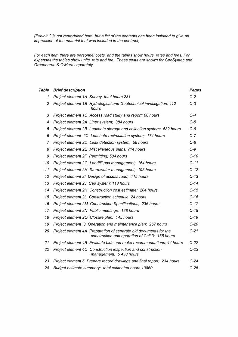
(Exhibit C is not reproduced here, but a list of the contents has been included to give animpression of the material that was included in the contract)
For each item there are personnel costs, and the tables show hours, rates and fees. Forexpenses the tables show units, rate and fee. These costs are shown for GeoSyntec andGreenhorne & O'Mara separately
Table Brief description Pages
1 Project element 1A Survey, total hours 281 C-2
2 Project element 1B Hydrological and Geotechnical investigation; 412hours
C-3
3 Project element 1C Access road study and report; 68 hours C-4
4 Project element 2A Liner system; 384 hours C-5
5 Project element 2B Leachate storage and collection system; 582 hours C-6
6 Project element 2C Leachate recirculation system; 174 hours C-7
7 Project element 2D Leak detection system; 58 hours C-8
8 Project element 2E Miscellaneous plans; 714 hours C-9
9 Project element 2F Permitting; 504 hours C-10
10 Project element 2G Landfill gas management; 164 hours C-11
11 Project element 2H Stormwater management; 193 hours C-12
12 Project element 2I Design of access road; 115 hours C-13
13 Project element 2J Cap system; 118 hours C-14
14 Project element 2K Construction cost estimate; 204 hours C-15
15 Project element 2L Construction schedule 24 hours C-16
16 Project element 2M Construction Specifications; 236 hours C-17
17 Project element 2N Public meetings; 138 hours C-18
18 Project element 2O Closure plan; 145 hours C-19
19 Project element 3 Operation and maintenance plan; 267 hours C-20
20 Project element 4A Preparation of separate bid documents for theconstruction and operation of Cell 3; 165 hours
C-21
21 Project element 4B Evaluate bids and make recommendations; 44 hours C-22
22 Project element 4C Construction inspection and constructionmanagement; 5,438 hours
C-23
23 Project element 5 Prepare record drawings and final report; 234 hours C-24
24 Budget estimate summary: total estimated hours 10860 C-25
EXHIBIT D
MANNER AND TIMES OF PAYMENT
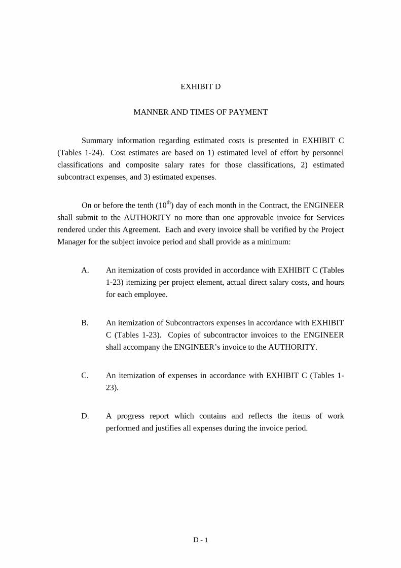
D - 1
EXHIBIT D
MANNER AND TIMES OF PAYMENT
Summary information regarding estimated costs is presented in EXHIBIT C
(Tables 1-24). Cost estimates are based on 1) estimated level of effort by personnel
classifications and composite salary rates for those classifications, 2) estimated
subcontract expenses, and 3) estimated expenses.
On or before the tenth (10th) day of each month in the Contract, the ENGINEER
shall submit to the AUTHORITY no more than one approvable invoice for Services
rendered under this Agreement. Each and every invoice shall be verified by the Project
Manager for the subject invoice period and shall provide as a minimum:
A. An itemization of costs provided in accordance with EXHIBIT C (Tables
1-23) itemizing per project element, actual direct salary costs, and hours
for each employee.
B. An itemization of Subcontractors expenses in accordance with EXHIBIT
C (Tables 1-23). Copies of subcontractor invoices to the ENGINEER
shall accompany the ENGINEER’s invoice to the AUTHORITY.
C. An itemization of expenses in accordance with EXHIBIT C (Tables 1-
23).
D. A progress report which contains and reflects the items of work
performed and justifies all expenses during the invoice period.
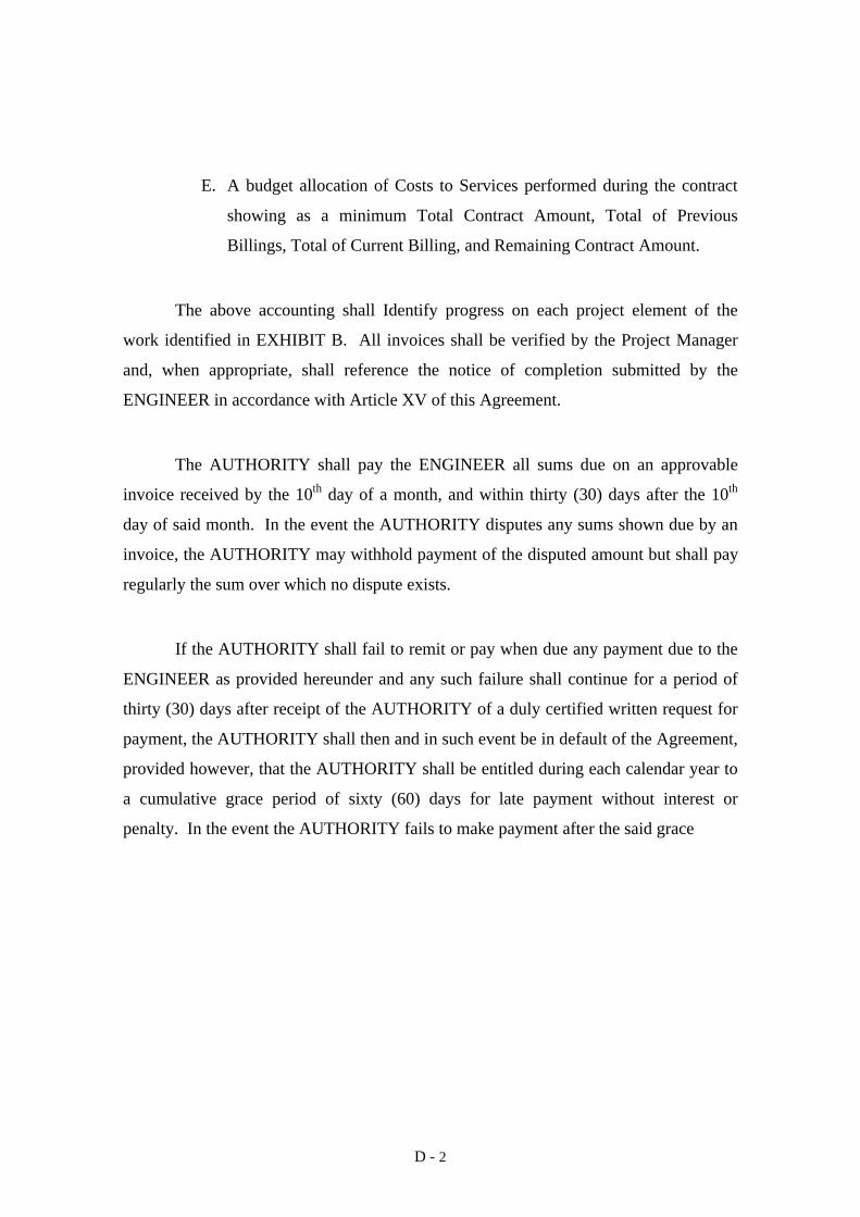
D - 2
E. A budget allocation of Costs to Services performed during the contract
showing as a minimum Total Contract Amount, Total of Previous
Billings, Total of Current Billing, and Remaining Contract Amount.
The above accounting shall Identify progress on each project element of the
work identified in EXHIBIT B. All invoices shall be verified by the Project Manager
and, when appropriate, shall reference the notice of completion submitted by the
ENGINEER in accordance with Article XV of this Agreement.
The AUTHORITY shall pay the ENGINEER all sums due on an approvable
invoice received by the 10th day of a month, and within thirty (30) days after the 10th
day of said month. In the event the AUTHORITY disputes any sums shown due by an
invoice, the AUTHORITY may withhold payment of the disputed amount but shall pay
regularly the sum over which no dispute exists.
If the AUTHORITY shall fail to remit or pay when due any payment due to the
ENGINEER as provided hereunder and any such failure shall continue for a period of
thirty (30) days after receipt of the AUTHORITY of a duly certified written request for
payment, the AUTHORITY shall then and in such event be in default of the Agreement,
provided however, that the AUTHORITY shall be entitled during each calendar year to
a cumulative grace period of sixty (60) days for late payment without interest or
penalty. In the event the AUTHORITY fails to make payment after the said grace
D - 3
period has been exhausted, the AUTHORITY shall be entitled to cure such default by
make full and complete payment to the ENGINEER shall be entitled to interest at the
lawful rate computed to the date of payment, and provided further that only one (1) such
sixty (60) day cure period shall be permitted in any calendar year. In the event the
AUTHORITY fails to make payment as required at the expiration of the cure period, the
ENGINEER may, at its option, terminate all of its duties and obligations hereunder.
To the extent that the ENGINEER, on audit, on request, or otherwise, is unable
to satisfactorily substantiate or document its cost, such sums shall be repaid to the
AUTHORITY, within thirty (30) days of such determination by the AUTHORITY or
others that sums are due the AUTHORITY.
In the event it is determined that monies wrongfully retained by one party were
rightly due to other party, the party wrongfully retaining the monies, in addition to
payment of the sum in dispute shall also pay interest on the monies retained in the
lawful rate from the time the said monies should have been paid.
In any proceeding, the burden of proof for all sums which the ENGINEER
claims is due it and/or which the ENGINEER seeks to retain, shall be on the
ENGINEER.