Embed Size (px)
Citation preview

1500 7700 W
WGlycolHFc co2
READy
Heatc
raft r
eserv
es its
elf th
e righ
t to m
ake c
hang
es at
any t
ime w
ithou
t prel
imina
ry no
tice -
Pho
tos no
n-co
ntrac
tual
Ceiling unit coolerMH/MHE commercial range
• The 24 models in the MH range meet the requirements of small storage cold rooms.
• Sturdy casing made of sheet steel with a low depth (228 to 260 mm) enabling optimum use of space in the cold room.
• Excellent air throw up to 17 m.
Natural fluids:Glycol water CO2 (R744)*
* Operating pressure 60 bar

28
DescriptionCasing• Sturdy and sober casing made of white pre-painted sheet steel.• Its low depth enables optimum use of storage space in the cold room.
Ventilation• The MH range is fitted with factory wired axial fans:Ø 300 mm: 230V 50-60 Hz, single-phase, IP42, class B.• The fan guards are compliant with safety standards (photo n°1).• 2 to 4 fans are necessary to cover the requirements of the entire range of capacities.Coil• The highly efficient and compact MH range finned coils are designed with corrugated
aluminium fins (fin spacing 4.23 or 6.35 mm) and internally grooved copper tubes.• The coils are supplied via a Venturi distributor.Defrost• Shielded electric heating elements are inserted in slots both on the front
and rear coil faces.• One of these shielded heating elements is also fastened in slots under the coil.
This slot assembly guarantees homogenous dispersion of heat over the entire coil.• The defrost heating elements are factory connected to a terminal block
(MHE range only). - 230V/1 power supply for all models MHE 320E, 380E and 250C, 310C.
- 400V/3 power supply for models MHE 460E, 550E, 640E, 770E and 370C, 450C, 510C, 630C.
Certifications
Designation
MHE(1) 250(2) C(3)
(1) MH = chill temp. models without defrost MHE = low temp. models with defrost (2) Model(3) Fin spacing: R / E = 4.23 mm - L / C = 6.35 mm
MH / MHE - Commercial ceiling unit cooler
Kit
Facto
ry
Options Ventilation
MM6 Fan 230 V/1/60 (contact us for details).Coil
BAE Paint coil protection.WCO Glycol water, coolant (please contact us for details).CO2 R744 optimization (please contact us for details).
DefrostE1K E1U Light electric defrost
THD(MHE)
For low temperature cold storage rooms with end of defrost thermostat with single-pole, reversing switch at +12℃ (±3 K) and delayed fan start up +2℃ (±3 K), supplied with a sensor and fastening bracket.Fully equipped unit coolers
DMP Expansion valve fitted.EEC Fully equipped unit cooler:
- Expansion valve fitted.- Solenoid valve fitted.- Piping pre-fitted with a ball valve(siphoning function provided by the collector).
AdvantagesInstallation
The expansion valve may be supplied factory pre-fitted (option DMP), as well as fully equipped (option EEC) to help reduce installation time.Servicing / Maintenance
The MH range has been designed for easy commissioning, maintenance and cleaning.The casing is fitted with hinges offering total access to all elements of the ceiling unit cooler (coil, fan, defrost heater, connections,...).The electric heating elements are fitted in slots under the coil offering unimpeded front access which considerably simplified maintenance.
Market segments
SUPERMARKET
SUPERMARKET
FOODSERVICE
PROCESSINDUSTRY
SUPERMARKET
SUPERMARKET
SUPERMARKET
FOODSERVICE
SUPERMARKET
SUPERMARKET
SUPERMARKET
SUPERMARKET
SUPERMARKET
PROCESSINDUSTRY
SUPERMARKET
SUPERMARKET
FOODSERVICE
SUPERMARKET
SUPERMARKET
SUPERMARKET
PROCESSINDUSTRY
SUPERMARKET
SUPERMARKET
FOODSERVICE
PROCESSINDUSTRY
•Bars - Restaurants - Corner shops - Mini-markets•Hard Discount - Supermarkets - Hypermarkets

28 29
C
571
607
==
A
B
531Ø = 1” G
ECF MM6 BAE WCO CO2 E1K E1U THD DMP EECO A� O A� A� O O - O O
tA1 MH ... +E1K MFE ...
+10 +2 -5 -10 -25°C
R404A CO2 W
MH ... 4,23 mm MH ... R 320 380 460 550 640 770
Capacity R404A (1) DT1 = 8K - SC 2 W 2882 3397 4365 5047 6016 6937Capacity CO2 (5) DT1 = 8K - SC 2 W 3209 3669 4773 5302 6130 7395Surface m2 9,73 12,98 14,60 19,47 19,61 26,15Circuit volume dm3 1,67 2,23 2,51 3,34 3,37 4,49Air flow m3/h 2290 2070 3430 3110 4600 4160
Fan230 V/1/50-60 Hz1,500 rpm.
Air throw (2) m 16 16 16 16 16 16Ø 300 mm Nb 2 2 3 3 4 4
230 V/1/50 Hz W max 2x 117 2x 117 3x 117 3x 117 4x 117 4x 117A max (3) 2x 0.77 2x 0.77 3x 0.77 3x 0.77 4x 0.77 4x 0.77
Net weight kg 34 35 46 48 54 57
DimensionsA mm 1531 1531 2197 2197 2499 2499B mm 1372 1372 2038 2038 2340 2340C mm 228 228 228 228 260 260
Connections R404A
Inlet Ø ODF (4) D 1/2" D 1/2" D 1/2" D 1/2" D 5/8" D 5/8"Outlet Ø ODF (4) 5/8" 5/8" 3/4" 3/4" 7/8" 7/8"
Connections (5)CO2
Inlet Ø ODF (4) 3/8" 3/8" 3/8" 3/8" 3/8" 1/2"Outlet Ø ODF (4) 3/8" 3/8" 3/8" 3/8" 3/8" 1/2"
MH ... 6,35 mm MH ... L 250 310 370 450 510 630
Capacity R404A (1) DT1 = 8K - SC 2 W 2344 2846 3540 4270 4748 5175Capacity CO2 (5) DT1 = 8K - SC 2 W 2783 3324 4186 4865 5440 6693Capacity W (6) DT1 = 8K W - 2660 - 3990 - 4810Surface m2 6,74 8,98 10,10 13,47 13,57 18,09Circuit volume dm3 1,67 2,23 2,51 3,34 3,37 4,49Air flow m3/h 2450 2290 3680 3430 4920 4590
Fan230 V/1/50-60 Hz1,500 rpm.
Air throw (2) m 17 17 17 17 17 17Ø 300 mm Nb 2 2 3 3 4 4
230 V/1/50 Hz W max 2x 117 2x 117 3x 117 3x 117 4x 117 4x 117A max (3) 2x 0.77 2x 0.77 3x 0.77 3x 0.77 4x 0.77 4x 0.77
Net weight kg 34 35 46 48 54 57
DimensionsA mm 1531 1531 2197 2197 2499 2499B mm 1372 1372 2038 2038 2340 2340C mm 228 228 228 228 260 260
Connections R404A
Inlet Ø ODF (4) D 1/2" D 1/2" D 1/2" D 1/2" D 5/8" D 5/8"Outlet Ø ODF (4) 5/8" 5/8" 3/4" 3/4" 7/8" 7/8"
Electric defrostE1K
Coil / Drain pan Nb 2 / 1 2 / 1 2 / 1 2 / 1 2 / 1 2 / 1W total 1800 1800 2700 2700 3600 3600
230 V/1/50Hz A total 7,83 7,83 11,70 11,70 15,70 15,70400 V/3/50Hz A total - - 3,90 3,90 5,20 5,20
(1) See page 12.(2) Residual air speed: 0.25 m/s.(3) Setting of overload protection levels. For air temperatures “ti” other than +20 °C, multiply the currents in relation to 293/(273 + “ti”) in order to obtain an approximate current value after the chamber temperature is attained.(4) ODF: Female to receive a tube of the same diameter.(5) Operating pressure 60 bar - Tube diameter to define the order.(6) Glycol water: Percent. glycol = 30% - Fluid inlet temp. = -8℃ – Fluid outlet temp. = -4℃ -Inlet dry temp. = +2°C – relative humidity = 85%.
30
ECF MM6 BAE WCO CO2 E1K E1U THD DMP EECO A� - - A� - - O O O
tA1 + ECK MHE ...
+10 +2 -5 -10 -25°C
R404A CO2
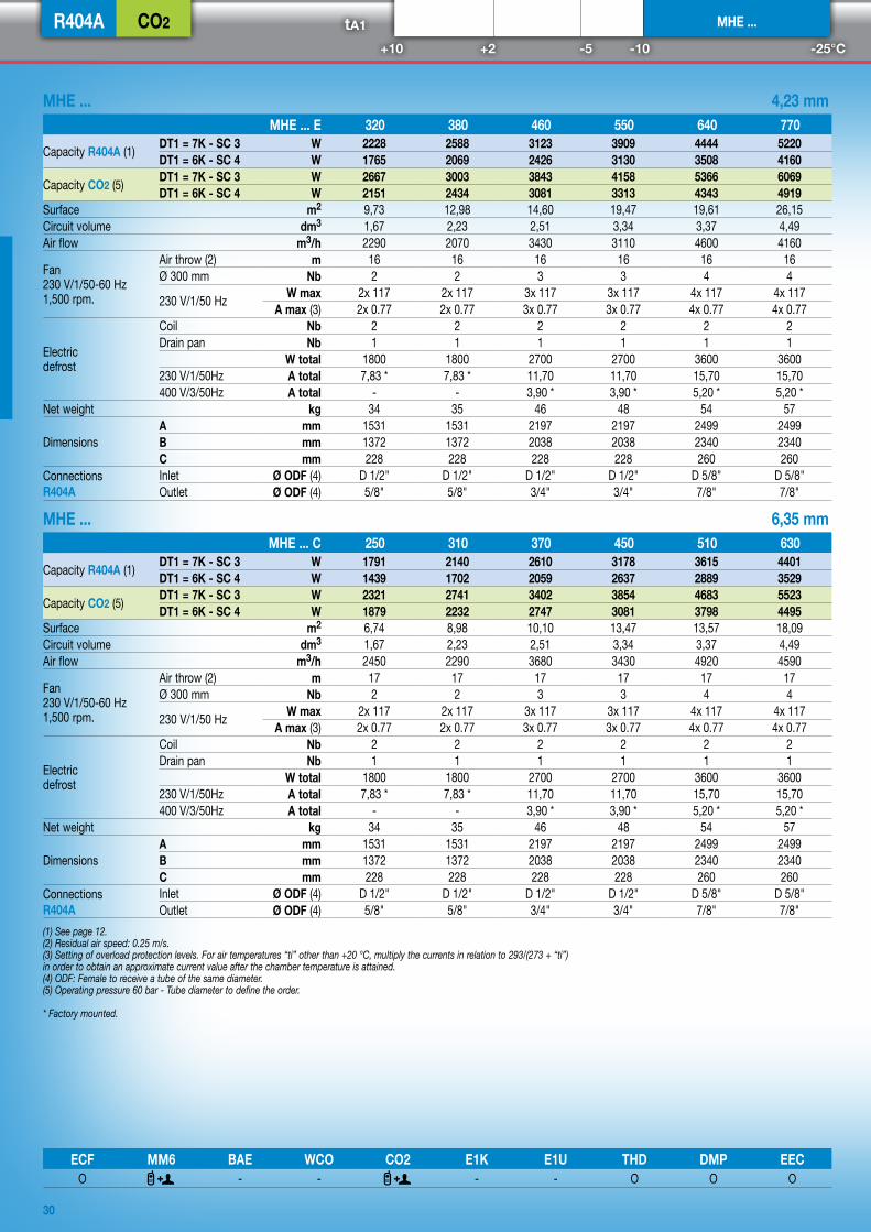
MHE ... 4,23 mm MHE ... E 320 380 460 550 640 770
Capacity R404A (1) DT1 = 7K - SC 3 W 2228 2588 3123 3909 4444 5220DT1 = 6K - SC 4 W 1765 2069 2426 3130 3508 4160
Capacity CO2 (5) DT1 = 7K - SC 3 W 2667 3003 3843 4158 5366 6069DT1 = 6K - SC 4 W 2151 2434 3081 3313 4343 4919
Surface m2 9,73 12,98 14,60 19,47 19,61 26,15Circuit volume dm3 1,67 2,23 2,51 3,34 3,37 4,49Air flow m3/h 2290 2070 3430 3110 4600 4160
Fan230 V/1/50-60 Hz1,500 rpm.
Air throw (2) m 16 16 16 16 16 16Ø 300 mm Nb 2 2 3 3 4 4
230 V/1/50 Hz W max 2x 117 2x 117 3x 117 3x 117 4x 117 4x 117A max (3) 2x 0.77 2x 0.77 3x 0.77 3x 0.77 4x 0.77 4x 0.77
Electric defrost
Coil Nb 2 2 2 2 2 2Drain pan Nb 1 1 1 1 1 1
W total 1800 1800 2700 2700 3600 3600230 V/1/50Hz A total 7,83 * 7,83 * 11,70 11,70 15,70 15,70400 V/3/50Hz A total - - 3,90 * 3,90 * 5,20 * 5,20 *
Net weight kg 34 35 46 48 54 57
DimensionsA mm 1531 1531 2197 2197 2499 2499B mm 1372 1372 2038 2038 2340 2340C mm 228 228 228 228 260 260
Connections R404A
Inlet Ø ODF (4) D 1/2" D 1/2" D 1/2" D 1/2" D 5/8" D 5/8"Outlet Ø ODF (4) 5/8" 5/8" 3/4" 3/4" 7/8" 7/8"
MHE ... 6,35 mm MHE ... C 250 310 370 450 510 630
Capacity R404A (1) DT1 = 7K - SC 3 W 1791 2140 2610 3178 3615 4401DT1 = 6K - SC 4 W 1439 1702 2059 2637 2889 3529
Capacity CO2 (5) DT1 = 7K - SC 3 W 2321 2741 3402 3854 4683 5523DT1 = 6K - SC 4 W 1879 2232 2747 3081 3798 4495
Surface m2 6,74 8,98 10,10 13,47 13,57 18,09Circuit volume dm3 1,67 2,23 2,51 3,34 3,37 4,49Air flow m3/h 2450 2290 3680 3430 4920 4590
Fan230 V/1/50-60 Hz1,500 rpm.
Air throw (2) m 17 17 17 17 17 17Ø 300 mm Nb 2 2 3 3 4 4
230 V/1/50 Hz W max 2x 117 2x 117 3x 117 3x 117 4x 117 4x 117A max (3) 2x 0.77 2x 0.77 3x 0.77 3x 0.77 4x 0.77 4x 0.77
Electric defrost
Coil Nb 2 2 2 2 2 2Drain pan Nb 1 1 1 1 1 1
W total 1800 1800 2700 2700 3600 3600230 V/1/50Hz A total 7,83 * 7,83 * 11,70 11,70 15,70 15,70400 V/3/50Hz A total - - 3,90 * 3,90 * 5,20 * 5,20 *
Net weight kg 34 35 46 48 54 57
DimensionsA mm 1531 1531 2197 2197 2499 2499B mm 1372 1372 2038 2038 2340 2340C mm 228 228 228 228 260 260
Connections R404A
Inlet Ø ODF (4) D 1/2" D 1/2" D 1/2" D 1/2" D 5/8" D 5/8"Outlet Ø ODF (4) 5/8" 5/8" 3/4" 3/4" 7/8" 7/8"
(1) See page 12.(2) Residual air speed: 0.25 m/s.(3) Setting of overload protection levels. For air temperatures “ti” other than +20 °C, multiply the currents in relation to 293/(273 + “ti”) in order to obtain an approximate current value after the chamber temperature is attained.(4) ODF: Female to receive a tube of the same diameter.(5) Operating pressure 60 bar - Tube diameter to define the order.
* Factory mounted.