Embed Size (px)
Citation preview
Ferdinand Schad KGSteigstraße 25-27
D-78600 KolbingenTelephone +49 (0) 74 63 - 980 - 0
Fax +49 (0) 74 63 - 980 - [email protected]
Ceiling Slot Diffuser DSC
Contents
Construction subject to change. No return possible!
Ceiling Slot Diffuser DSC
04/02 - 2 05.04.2013Version:
Description ........................................................................................................................................3Construction .............................................................................................................................................................................. 3Model ......................................................................................................................................................................................... 3Accessories ................................................................................................................................................................................ 4Fastening ................................................................................................................................................................................... 4
Models and dimensions .........................................................................................................................5Air throw pattern ........................................................................................................................................................................ 5Dimensions ................................................................................................................................................................................ 6Dimensions of accessories ........................................................................................................................................................ 7Fastening methods ................................................................................................................................................................... 14Screw mounting (-SM) ............................................................................................................................................................ 15Concealed mounting (-VM) ...................................................................................................................................................... 16Clamp fastening (-KB) .............................................................................................................................................................. 18
Technical data .................................................................................................................................. 19Pressure loss and noise level ................................................................................................................................................... 19Maximum end velocity of jet .................................................................................................................................................... 21Critical throw ........................................................................................................................................................................... 23Maximum penetration .............................................................................................................................................................. 23Temperature ratios ................................................................................................................................................................... 24
Legend ........................................................................................................................................... 25Order details .................................................................................................................................... 26Specification texts .............................................................................................................................. 28
Ceiling Slot Diffuser DSC
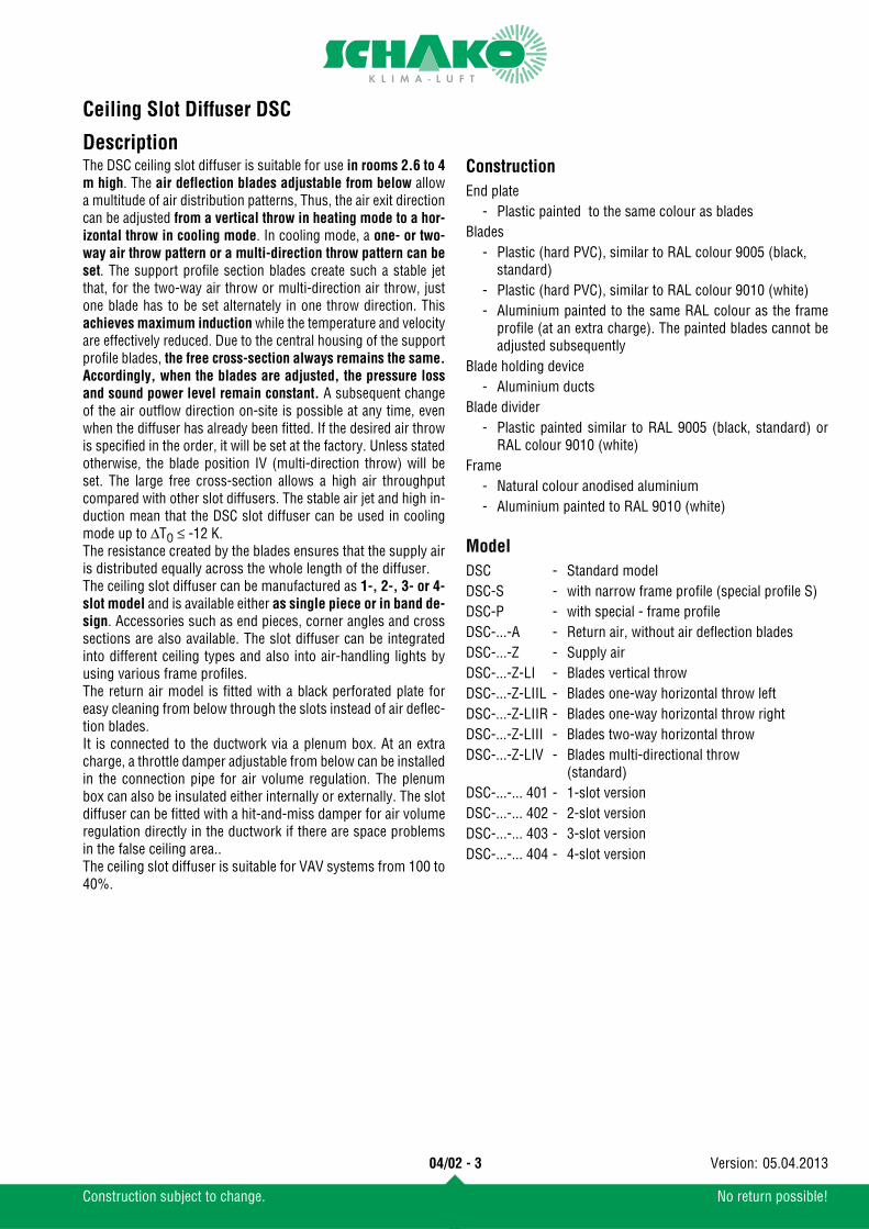
DescriptionThe DSC ceiling slot diffuser is suitable for use in rooms 2.6 to 4m high. The air deflection blades adjustable from below allowa multitude of air distribution patterns, Thus, the air exit directioncan be adjusted from a vertical throw in heating mode to a hor-izontal throw in cooling mode. In cooling mode, a one- or two-way air throw pattern or a multi-direction throw pattern can beset. The support profile section blades create such a stable jetthat, for the two-way air throw or multi-direction air throw, justone blade has to be set alternately in one throw direction. Thisachieves maximum induction while the temperature and velocityare effectively reduced. Due to the central housing of the supportprofile blades, the free cross-section always remains the same.Accordingly, when the blades are adjusted, the pressure lossand sound power level remain constant. A subsequent changeof the air outflow direction on-site is possible at any time, evenwhen the diffuser has already been fitted. If the desired air throwis specified in the order, it will be set at the factory. Unless statedotherwise, the blade position IV (multi-direction throw) will beset. The large free cross-section allows a high air throughputcompared with other slot diffusers. The stable air jet and high in-duction mean that the DSC slot diffuser can be used in coolingmode up to ΔTO ≤ -12 K.The resistance created by the blades ensures that the supply airis distributed equally across the whole length of the diffuser.The ceiling slot diffuser can be manufactured as 1-, 2-, 3- or 4-slot model and is available either as single piece or in band de-sign. Accessories such as end pieces, corner angles and crosssections are also available. The slot diffuser can be integratedinto different ceiling types and also into air-handling lights byusing various frame profiles.The return air model is fitted with a black perforated plate foreasy cleaning from below through the slots instead of air deflec-tion blades.It is connected to the ductwork via a plenum box. At an extracharge, a throttle damper adjustable from below can be installedin the connection pipe for air volume regulation. The plenumbox can also be insulated either internally or externally. The slotdiffuser can be fitted with a hit-and-miss damper for air volumeregulation directly in the ductwork if there are space problemsin the false ceiling area..The ceiling slot diffuser is suitable for VAV systems from 100 to40%.
Construction
Model
End plate- Plastic painted to the same colour as blades
Blades- Plastic (hard PVC), similar to RAL colour 9005 (black,
standard)- Plastic (hard PVC), similar to RAL colour 9010 (white)- Aluminium painted to the same RAL colour as the frame
profile (at an extra charge). The painted blades cannot beadjusted subsequently
Blade holding device- Aluminium ducts
Blade divider- Plastic painted similar to RAL 9005 (black, standard) or
RAL colour 9010 (white)Frame
- Natural colour anodised aluminium- Aluminium painted to RAL 9010 (white)
DSC - Standard modelDSC-S - with narrow frame profile (special profile S)DSC-P - with special - frame profileDSC-...-A - Return air, without air deflection bladesDSC-...-Z - Supply airDSC-...-Z-LI - Blades vertical throwDSC-...-Z-LIIL - Blades one-way horizontal throw leftDSC-...-Z-LIIR - Blades one-way horizontal throw rightDSC-...-Z-LIII - Blades two-way horizontal throwDSC-...-Z-LIV - Blades multi-directional throw
(standard)DSC-...-... 401 - 1-slot versionDSC-...-... 402 - 2-slot versionDSC-...-... 403 - 3-slot versionDSC-...-... 404 - 4-slot version
04/02 - 3
Construction subject to change. No return possible!
05.04.2013Version:
Ceiling Slot Diffuser DSC
Accessories FasteningPlenum box (-ASK)
- Galvanised sheet steel- Box end cover (-K) (with VM mounting, pair, fastening on site)
Dummy profile (-BP)- Aluminium painted to the same colour as frame
Throttle damper (-DK)- Galvanised sheet steel, in plenum box (-ASK)
Corner angle 90° (-EW)- Aluminium (same colour as frame)
M4 Riveting nuts (-EM)- Brass
End pieces (pair) (-ES)- supplied loose as standard. If there are order details re-
garding fitting, mounting will take place at the factory.- Aluminium (same colour as frame)
Rubber lip seal (-GD)- Special rubber
Cross point (-KP)- Sheet steel painted to the same colour as frame
Hit-and-miss damper (SS-K)- Electrolytically galvanised sheet steel (only possible with-
out plenum box (-ASK))Fishplate (-VL)
- supplied loose as standard - Aluminium (same colour as frame)
Additional profile- Aluminium (same colour as frame)- Z I: Mounting of ceiling panels (for DSC-S)- Z II Mounting of panelled ceilings (for DSC-S)- Z III: Mounting of ceiling panels (for DSC-S)- Z V: Mounting of light ceilings (for DSC-S)
Internal insulation (-Ii)- Thermal insulation at the inside of the plenum box
External insulation (-Ia)- Thermal insulation at the outside of the plenum box
Permanent connection (-FV)- As standard for the versions DSC, DSC-S and DSC-P with
plenum boxClamp fastening (-KB)
- possible for versions DSC and DSC-P without plenum box ASK- supplied loose as standard - not possible for version DSC-S
Screw mounting (-SM)- possible for versions DSC and DSC-P without plenum box,
screws on site- not possible for version DSC-S
Concealed mounting (-VM)- possible for versions DSC and DSC-P- not possible for version DSC-S
suspension lugs (-AL)- possible for versions DSC and DSC-P without plenum box ASK- not possible for version DSC-S
04/02 - 4
Construction subject to change. No return possible!
05.04.2013Version:
Ceiling Slot Diffuser DSC
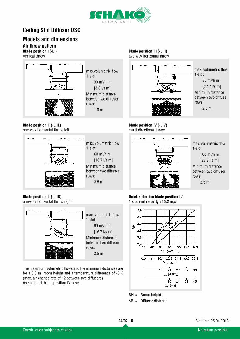
Models and dimensionsAir throw patternBlade position I (-LI)Vertical throw
Blade position II (-LIIL)one-way horizontal throw left
Blade position II (-LIIR)one-way horizontal throw right
The maximum volumetric flows and the minimum distances arefor a 3.0 m room height and a temperature difference of -8 K(max. air change rate of 12 between two diffusers)As standard, blade position IV is set.
Blade position III (-LIII)two-way horizontal throw
Blade position IV (-LIV)multi-directional throw
Quick selection blade position IV1 slot end velocity of 0.2 m/s
max.volumetric flow1-slot
30 m³/h m[8.3 l/s m]
Minimum distance betweentwo diffuser rows:
1.0 m
max. volumetric flow 1-slot
60 m³/h m[16.7 l/s m]
Minimum distance between two diffuser rows:
3.5 m
max. volumetric flow 1-slot
60 m³/h m[16.7 l/s m]
Minimum distance between two diffuser rows:
3.5 m
RH = Room heightAB = Diffuser distance
max. volumetric flow 1-slot
80 m³/h m[22.2 l/s m]
Minimum distance between two diffuser rows:
2.5 m
max. volumetric flow 1-slot
100 m³/h m[27.8 l/s m]
Minimum distance between two diffuser rows:
2.5 m
04/02 - 5
Construction subject to change. No return possible!
05.04.2013Version:
Ceiling Slot Diffuser DSC
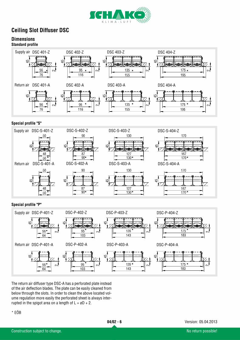
DimensionsStandard profile
Special profile "S"
Special profile "P"
The return air diffuser type DSC-A has a perforated plate insteadof the air deflection blades. The plate can be easily cleaned frombelow through the slots. In order to clean the above located vol-ume regulation more easily the perforated sheet is always inter-rupted in the spigot area on a length of L = øD + 2.
* EÖB
Return air
Supply air DSC 401-Z DSC 402-Z DSC 403-Z DSC 404-Z
DSC 401-A DSC 402-A DSC 403-A DSC 404-A
*
* *
**
*
*
*
DSC-S-401-Z DSC-S-402-Z DSC-S-403-Z DSC-S-404-Z
Return air
Supply air
DSC-S-401-A DSC-S-402-A DSC-S-403-A DSC-S-404-A
*
*
*
*
*
*
*
*
DSC-P-401-Z DSC-P-402-Z DSC-P-403-Z DSC-P-404-Z
Return air
Supply air
DSC-P-401-A DSC-P-402-A DSC-P-403-A DSC-P-404-A
*
*
*
*
*
*
*
*
04/02 - 6
Construction subject to change. No return possible!
05.04.2013Version:
Ceiling Slot Diffuser DSC
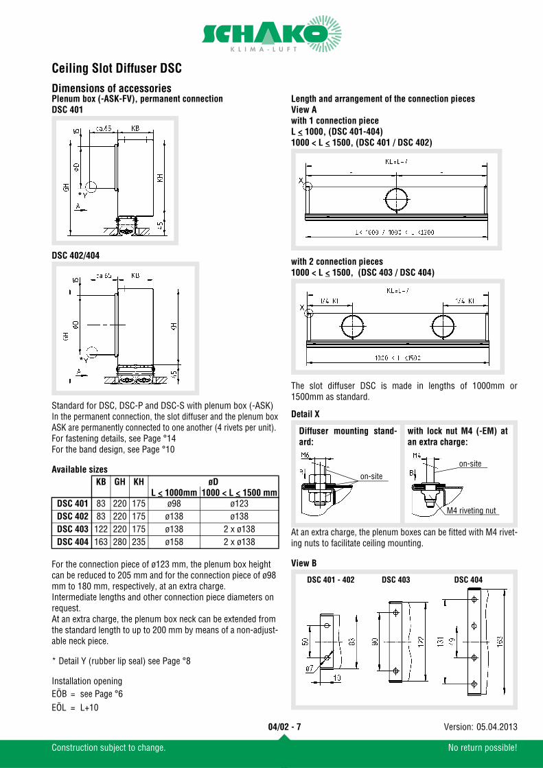
Dimensions of accessoriesPlenum box (-ASK-FV), permanent connectionDSC 401
DSC 402/404
Standard for DSC, DSC-P and DSC-S with plenum box (-ASK)In the permanent connection, the slot diffuser and the plenum boxASK are permanently connected to one another (4 rivets per unit).For fastening details, see Page °14For the band design, see Page °10
Available sizes
For the connection piece of ø123 mm, the plenum box height can be reduced to 205 mm and for the connection piece of ø98 mm to 180 mm, respectively, at an extra charge.Intermediate lengths and other connection piece diameters on request.At an extra charge, the plenum box neck can be extended from the standard length to up to 200 mm by means of a non-adjust-able neck piece.
* Detail Y (rubber lip seal) see Page °8
Installation opening
Length and arrangement of the connection piecesView Awith 1 connection pieceL < 1000, (DSC 401-404)1000 < L < 1500, (DSC 401 / DSC 402)
with 2 connection pieces1000 < L < 1500, (DSC 403 / DSC 404)
The slot diffuser DSC is made in lengths of 1000mm or1500mm as standard.
Detail X
At an extra charge, the plenum boxes can be fitted with M4 rivet-ing nuts to facilitate ceiling mounting.
View B
KB GH KH øDL < 1000mm 1000 < L < 1500 mm
DSC 401 83 220 175 ø98 ø123DSC 402 83 220 175 ø138 ø138DSC 403 122 220 175 ø138 2 x ø138DSC 404 163 280 235 ø158 2 x ø138
EÖB = see Page °6EÖL = L+10
*
*
on-site
on-site
M4 riveting nut
Diffuser mounting stand-ard:
with lock nut M4 (-EM) atan extra charge:
DSC 401 - 402 DSC 403 DSC 404
04/02 - 7
Construction subject to change. No return possible!
05.04.2013Version:
Ceiling Slot Diffuser DSC
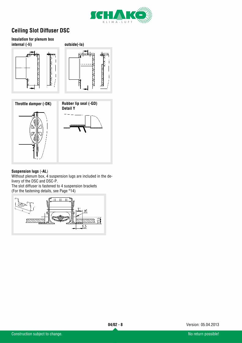
Insulation for plenum boxSuspension lugs (-AL)Without plenum box, 4 suspension lugs are included in the de-livery of the DSC and DSC-P.The slot diffuser is fastened to 4 suspension brackets (For the fastening details, see Page °14)
internal (-Ii) outside(-Ia)
Throttle damper (-DK) Rubber lip seal (-GD)Detail Y
04/02 - 8
Construction subject to change. No return possible!
05.04.2013Version:
Ceiling Slot Diffuser DSC
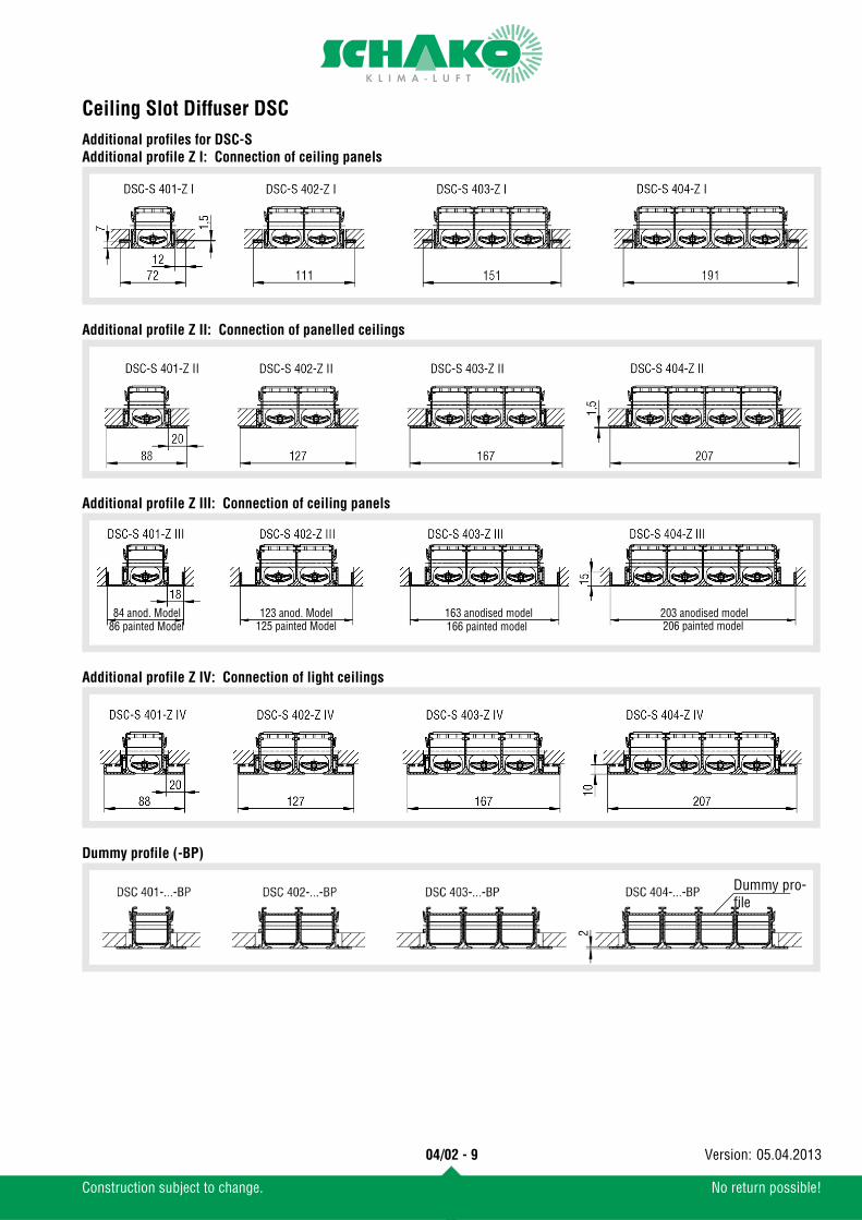
Additional profiles for DSC-SAdditional profile Z I: Connection of ceiling panelsAdditional profile Z II: Connection of panelled ceilings
Additional profile Z III: Connection of ceiling panels
Additional profile Z IV: Connection of light ceilings
Dummy profile (-BP)
166 painted model86 painted Model 125 painted Model 206 painted model123 anod. Model 203 anodised model84 anod. Model 163 anodised model
Dummy pro-file
04/02 - 9
Construction subject to change. No return possible!
05.04.2013Version:
Ceiling Slot Diffuser DSC
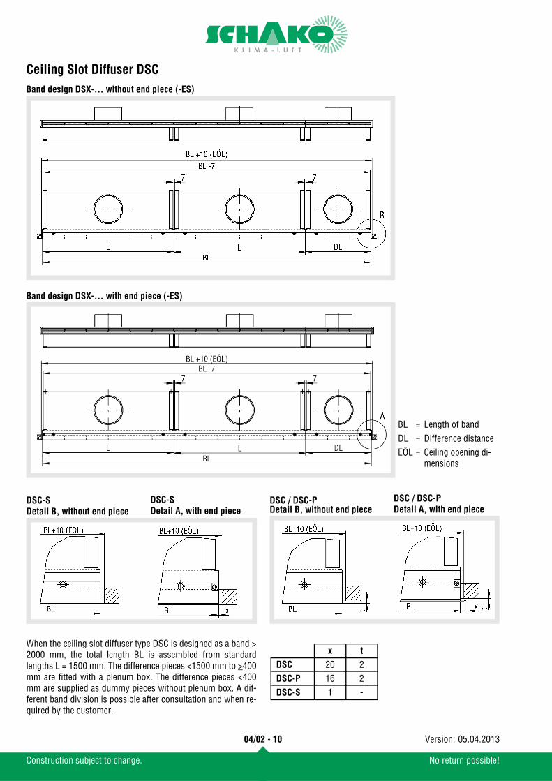
Band design DSX-... without end piece (-ES)Band design DSX-... with end piece (-ES)
DSC-SDetail B, without end piece
DSC / DSC-PDetail B, without end piece
When the ceiling slot diffuser type DSC is designed as a band >2000 mm, the total length BL is assembled from standardlengths L = 1500 mm. The difference pieces <1500 mm to >400mm are fitted with a plenum box. The difference pieces <400mm are supplied as dummy pieces without plenum box. A dif-ferent band division is possible after consultation and when re-quired by the customer.
BL = Length of bandDL = Difference distanceEÖL = Ceiling opening di-
mensions
x t
DSC 20 2DSC-P 16 2DSC-S 1 -
DSC-SDetail A, with end piece
DSC / DSC-PDetail A, with end piece
04/02 - 10
Construction subject to change. No return possible!
05.04.2013Version:
Ceiling Slot Diffuser DSC
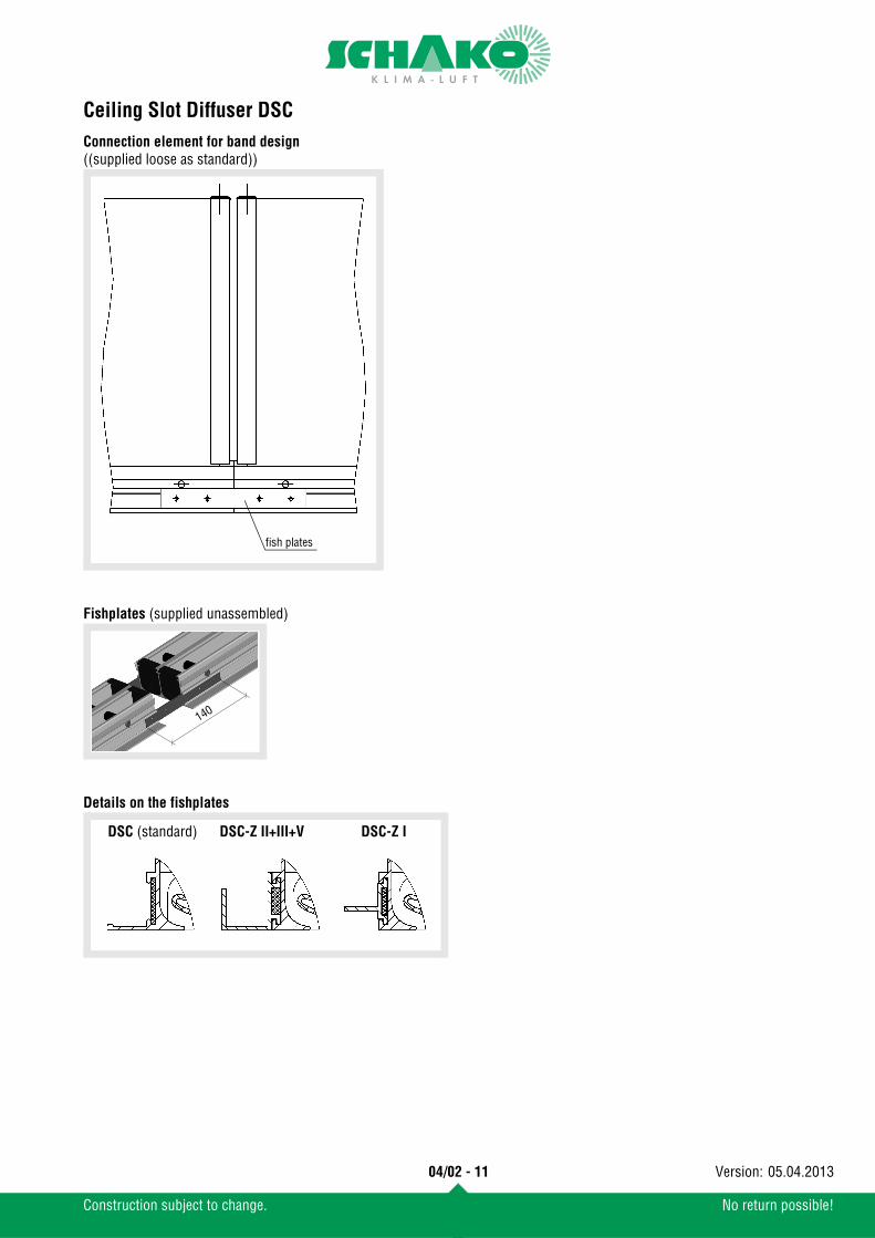
Connection element for band design((supplied loose as standard))Fishplates (supplied unassembled)
Details on the fishplates
fish plates
140
DSC (standard) DSC-Z II+III+V DSC-Z I
04/02 - 11
Construction subject to change. No return possible!
05.04.2013Version:
Ceiling Slot Diffuser DSC
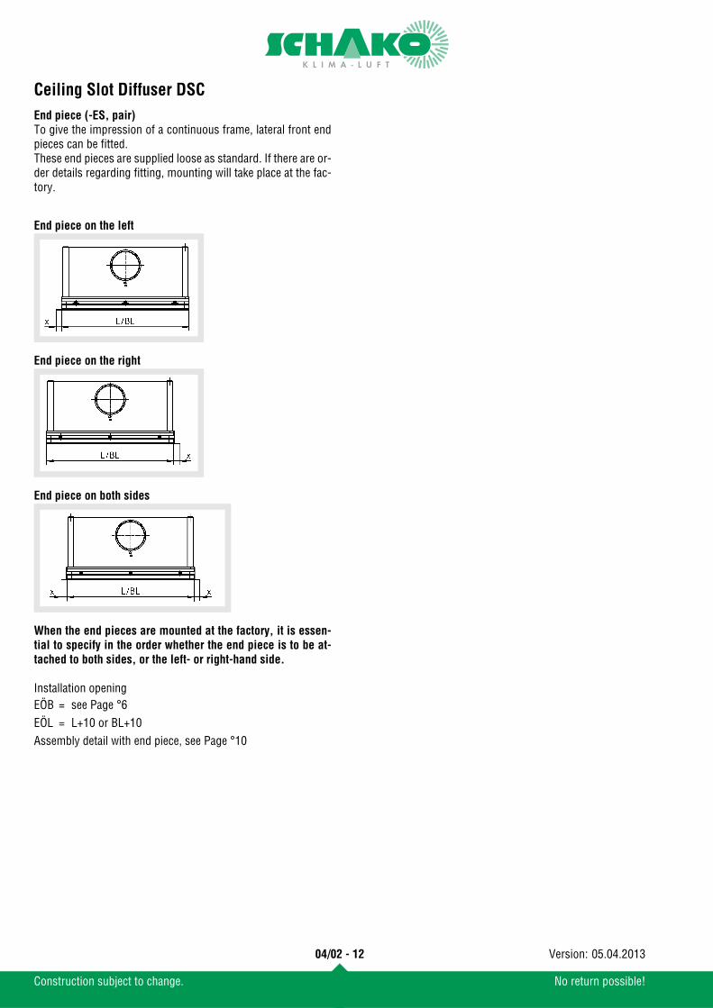
End piece (-ES, pair)To give the impression of a continuous frame, lateral front endpieces can be fitted. These end pieces are supplied loose as standard. If there are or-der details regarding fitting, mounting will take place at the fac-tory.End piece on the left
End piece on the right
End piece on both sides
When the end pieces are mounted at the factory, it is essen-tial to specify in the order whether the end piece is to be at-tached to both sides, or the left- or right-hand side.
Installation opening
Assembly detail with end piece, see Page °10
EÖB = see Page °6EÖL = L+10 or BL+10
04/02 - 12
Construction subject to change. No return possible!
05.04.2013Version:
Ceiling Slot Diffuser DSC
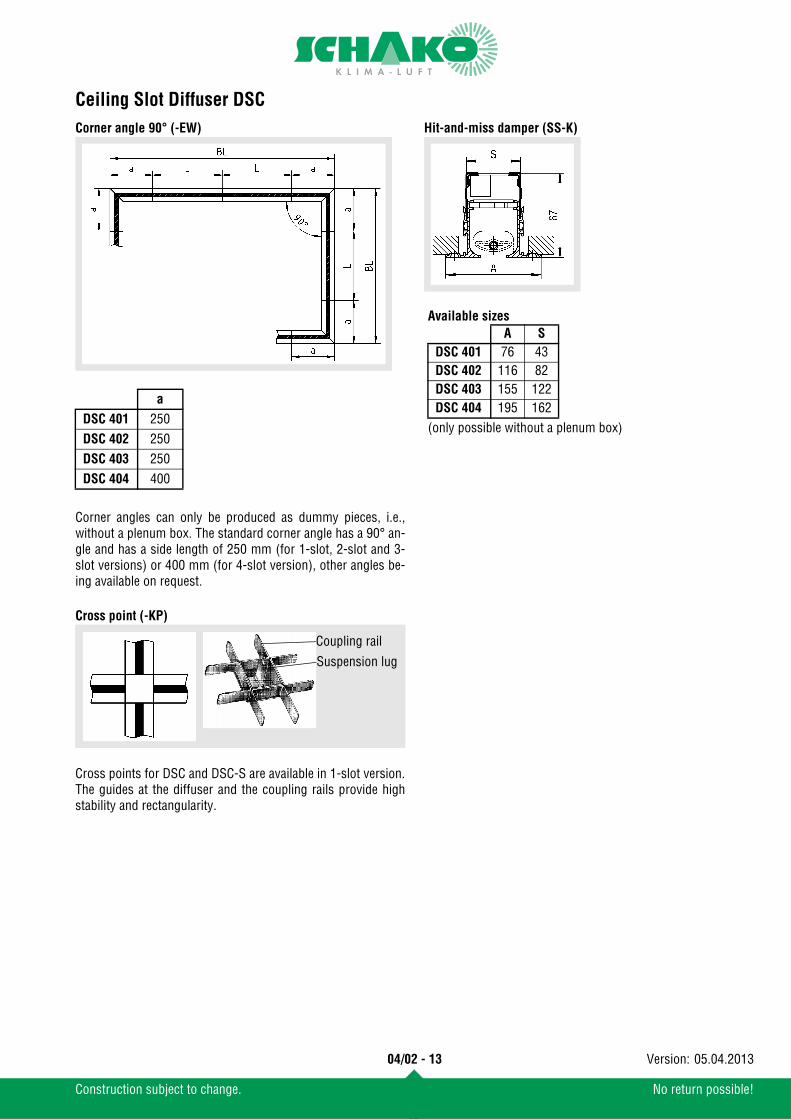
Corner angle 90° (-EW)Corner angles can only be produced as dummy pieces, i.e.,without a plenum box. The standard corner angle has a 90° an-gle and has a side length of 250 mm (for 1-slot, 2-slot and 3-slot versions) or 400 mm (for 4-slot version), other angles be-ing available on request.
Cross point (-KP)
Cross points for DSC and DSC-S are available in 1-slot version.The guides at the diffuser and the coupling rails provide highstability and rectangularity.
Hit-and-miss damper (SS-K)
a
DSC 401 250DSC 402 250DSC 403 250DSC 404 400
Coupling rail
Suspension lug
Available sizes
(only possible without a plenum box)
A SDSC 401 76 43DSC 402 116 82DSC 403 155 122DSC 404 195 162
04/02 - 13
Construction subject to change. No return possible!
05.04.2013Version:
Ceiling Slot Diffuser DSC
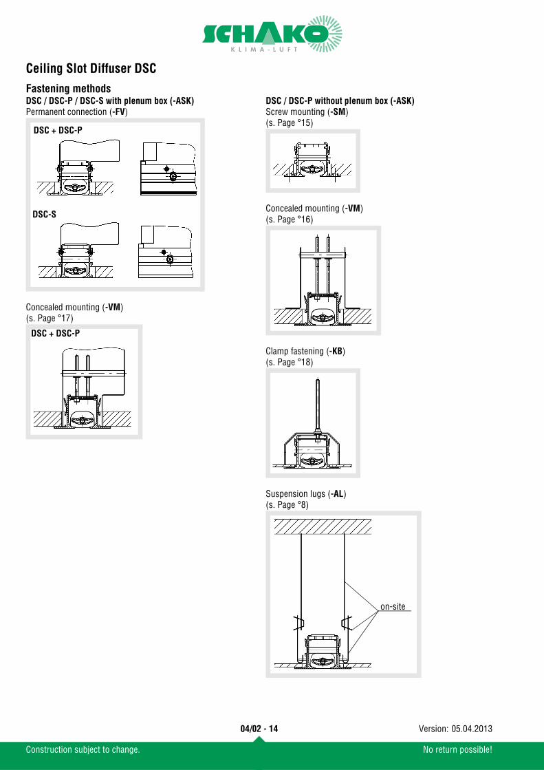
Fastening methodsDSC / DSC-P / DSC-S with plenum box (-ASK)Permanent connection (-FV)
Concealed mounting (-VM)(s. Page °17)
DSC / DSC-P without plenum box (-ASK)Screw mounting (-SM)(s. Page °15)
Concealed mounting (-VM)(s. Page °16)
Clamp fastening (-KB)(s. Page °18)
Suspension lugs (-AL)(s. Page °8)
DSC + DSC-P
DSC-S
DSC + DSC-P
on-site
04/02 - 14
Construction subject to change. No return possible!
05.04.2013Version:
Ceiling Slot Diffuser DSC
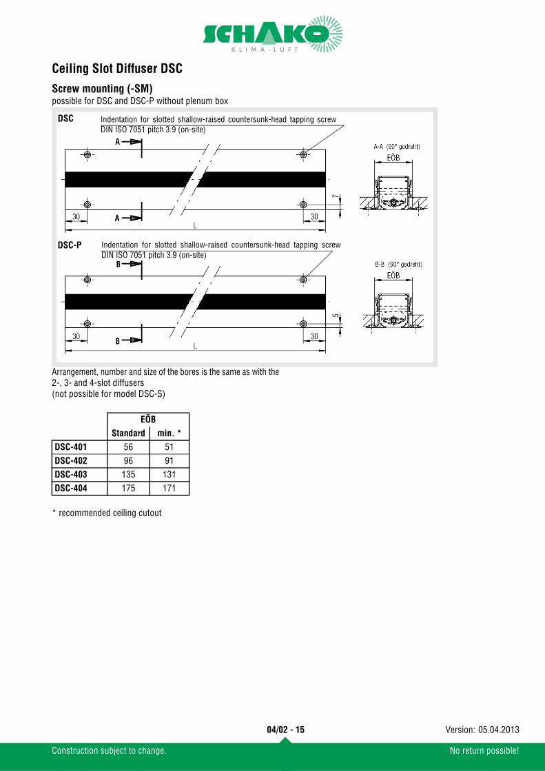
Screw mounting (-SM)possible for DSC and DSC-P without plenum box
Arrangement, number and size of the bores is the same as with the2-, 3- and 4-slot diffusers(not possible for model DSC-S)
* recommended ceiling cutout
Indentation for slotted shallow-raised countersunk-head tapping screwDIN ISO 7051 pitch 3.9 (on-site)
Indentation for slotted shallow-raised countersunk-head tapping screwDIN ISO 7051 pitch 3.9 (on-site)
DSC
DSC-P
EÖB
Standard min. *
DSC-401 56 51DSC-402 96 91DSC-403 135 131DSC-404 175 171
04/02 - 15
Construction subject to change. No return possible!
05.04.2013Version:
Ceiling Slot Diffuser DSC
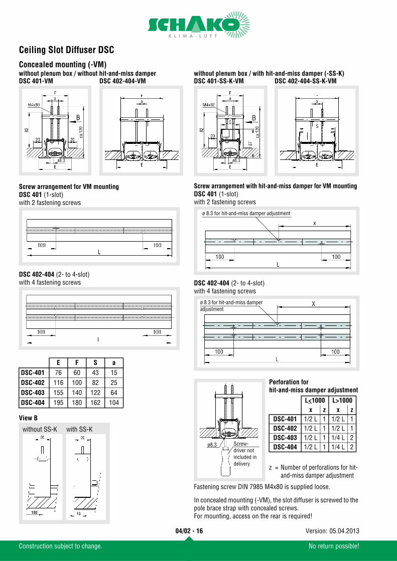
Concealed mounting (-VM)without plenum box / without hit-and-miss damper
Screw arrangement for VM mountingDSC 401 (1-slot)with 2 fastening screws
DSC 402-404 (2- to 4-slot)with 4 fastening screws
View B
without plenum box / with hit-and-miss damper (-SS-K)
Screw arrangement with hit-and-miss damper for VM mountingDSC 401 (1-slot)with 2 fastening screws
DSC 402-404 (2- to 4-slot)with 4 fastening screws
Fastening screw DIN 7985 M4x80 is supplied loose.
In concealed mounting (-VM), the slot diffuser is screwed to the pole brace strap with concealed screws.For mounting, access on the rear is required!
E F S a
DSC-401 76 60 43 15DSC-402 116 100 82 25DSC-403 155 140 122 64DSC-404 195 180 162 104
DSC 401-VM DSC 402-404-VM
without SS-K with SS-K
DSC 401-SS-K-VM DSC 402-404-SS-K-VM
ø 8.3 for hit-and-miss damper adjustment
ø 8.3 for hit-and-miss damper adjustment
Screw-driver notincluded in delivery
ø8,3
Perforation forhit-and-miss damper adjustment
L<1000 L>1000x z x z
DSC-401 1/2 L 1 1/2 L 1DSC-402 1/2 L 1 1/2 L 1DSC-403 1/2 L 1 1/4 L 2DSC-404 1/2 L 1 1/4 L 2
z = Number of perforations for hit-and-miss damper adjustment
04/02 - 16
Construction subject to change. No return possible!
05.04.2013Version:
Ceiling Slot Diffuser DSC
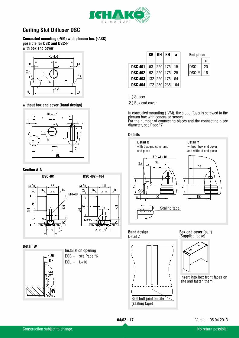
Concealed mounting (-VM) with plenum box (-ASK)possible for DSC and DSC-Pwith box end coverwithout box end cover (band design)
Section A-A
Detail W
In concealed mounting (-VM), the slot diffuser is screwed to theplenum box with concealed screws.For the number of connecting pieces and the connecting piecediameter, see Page °7
Details
1.)2.)
2.)
1.)
DSC 401 DSC 402 - 404
KB GH KH a End piece
xDSC 401 53 220 175 15 DSC 20DSC 402 92 220 175 25 DSC-P 16DSC 403 132 220 175 64DSC 404 172 280 235 104
1.) Spacer2.) Box end cover
Detail Xwith box end cover and end piece
Detail Ywithout box end cover and without end piece
2.)
Sealing tape
Detail Z
Seal butt joint on site (sealing tape)
Band design
Insert into box front faces onsite and fasten them.
Box end cover (pair)(Supplied loose)
Installation openingEÖB = see Page °6EÖL = L+10
04/02 - 17
Construction subject to change. No return possible!
05.04.2013Version:
Ceiling Slot Diffuser DSC
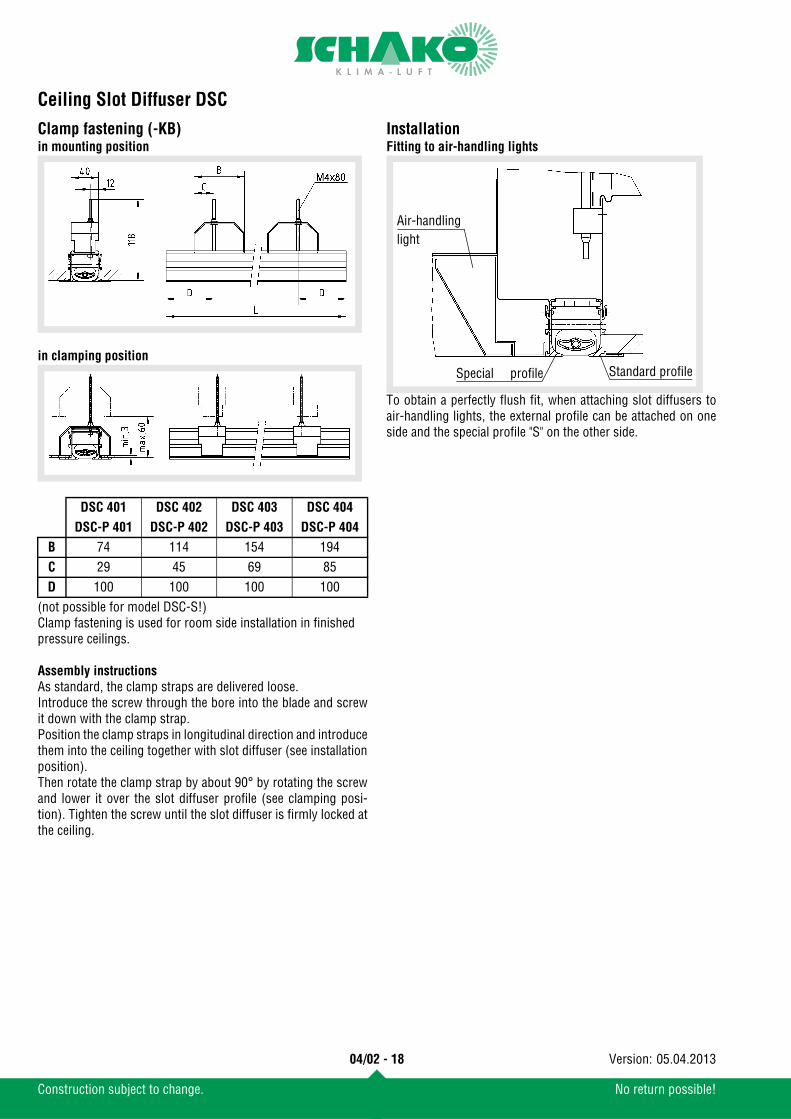
Clamp fastening (-KB)in mounting position
in clamping position
(not possible for model DSC-S!)Clamp fastening is used for room side installation in finished pressure ceilings.
Assembly instructionsAs standard, the clamp straps are delivered loose. Introduce the screw through the bore into the blade and screwit down with the clamp strap.Position the clamp straps in longitudinal direction and introducethem into the ceiling together with slot diffuser (see installationposition).Then rotate the clamp strap by about 90° by rotating the screwand lower it over the slot diffuser profile (see clamping posi-tion). Tighten the screw until the slot diffuser is firmly locked atthe ceiling.
InstallationFitting to air-handling lights
To obtain a perfectly flush fit, when attaching slot diffusers toair-handling lights, the external profile can be attached on oneside and the special profile "S" on the other side.
DSC 401 DSC 402 DSC 403 DSC 404
DSC-P 401 DSC-P 402 DSC-P 403 DSC-P 404
B 74 114 154 194C 29 45 69 85D 100 100 100 100
Air-handlinglight
Standard profileSpecial profile
04/02 - 18
Construction subject to change. No return possible!
05.04.2013Version:
Ceiling Slot Diffuser DSC
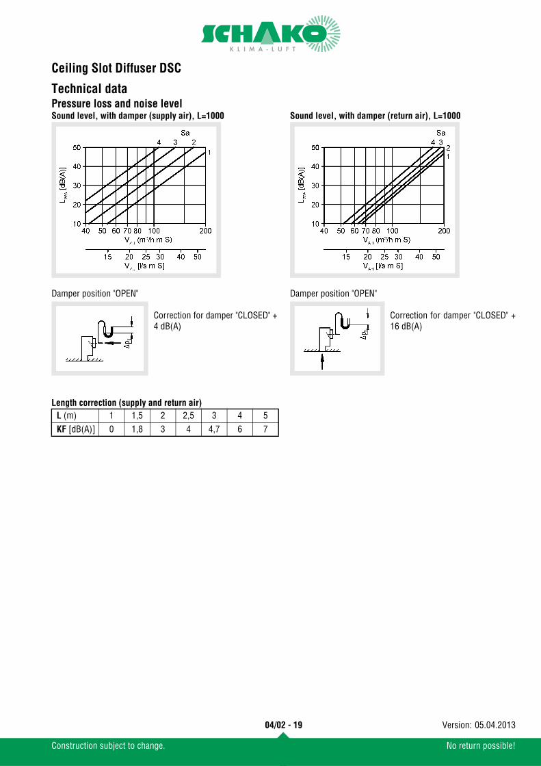
Technical dataPressure loss and noise levelSound level, with damper (supply air), L=1000
Damper position "OPEN"
Correction for damper "CLOSED" +4 dB(A)
Sound level, with damper (return air), L=1000
Damper position "OPEN"
Correction for damper "CLOSED" +16 dB(A)
Length correction (supply and return air)L (m) 1 1,5 2 2,5 3 4 5KF [dB(A)] 0 1,8 3 4 4,7 6 7
04/02 - 19
Construction subject to change. No return possible!
05.04.2013Version:
Ceiling Slot Diffuser DSC
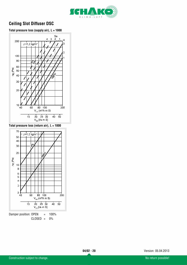
Total pressure loss (supply air), L = 1000Total pressure loss (return air), L = 1000
Damper position: OPEN = 100%CLOSED = 0%
04/02 - 20
Construction subject to change. No return possible!
05.04.2013Version:
Ceiling Slot Diffuser DSC
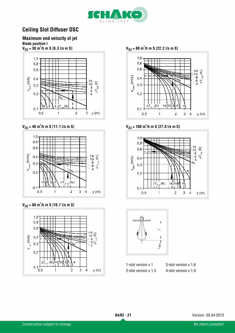
Maximum end velocity of jetBlade position IVZU = 30 m³/h m S [8.3 l/s m S]
VZU = 40 m³/h m S [11.1 l/s m S]
VZU = 60 m³/h m S [16.7 l/s m S]
VZU = 80 m³/h m S [22.2 l/s m S]
VZU = 100 m³/h m S [27.8 l/s m S]
1-slot version x 1 3-slot version x 1.62-slot version x 1.3 4-slot version x 1.9
04/02 - 21
Construction subject to change. No return possible!
05.04.2013Version:
Ceiling Slot Diffuser DSC
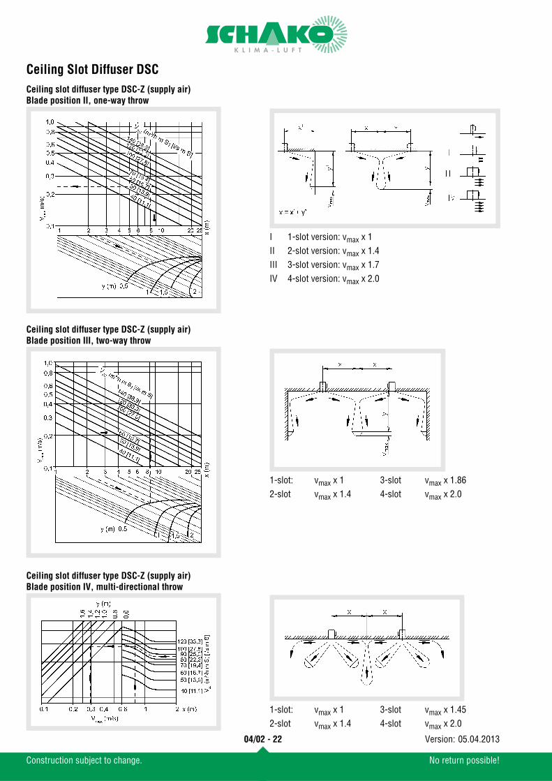
Ceiling slot diffuser type DSC-Z (supply air)Blade position II, one-way throwCeiling slot diffuser type DSC-Z (supply air)Blade position III, two-way throw
Ceiling slot diffuser type DSC-Z (supply air)Blade position IV, multi-directional throw
I 1-slot version: vmax x 1II 2-slot version: vmax x 1.4III 3-slot version: vmax x 1.7IV 4-slot version: vmax x 2.0
1-slot: vmax x 1 3-slot vmax x 1.862-slot vmax x 1.4 4-slot vmax x 2.0
1-slot: vmax x 1 3-slot vmax x 1.452-slot vmax x 1.4 4-slot vmax x 2.0
04/02 - 22
Construction subject to change. No return possible!
05.04.2013Version:
Ceiling Slot Diffuser DSC
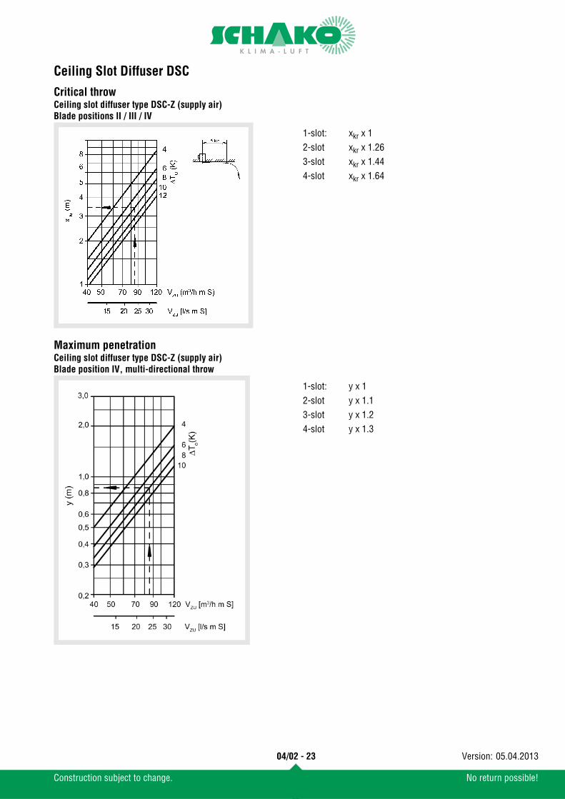
Critical throwCeiling slot diffuser type DSC-Z (supply air)Blade positions II / III / IV
Maximum penetrationCeiling slot diffuser type DSC-Z (supply air)Blade position IV, multi-directional throw
1-slot: xkr x 12-slot xkr x 1.263-slot xkr x 1.444-slot xkr x 1.64
1-slot: y x 12-slot y x 1.13-slot y x 1.24-slot y x 1.3
04/02 - 23
Construction subject to change. No return possible!
05.04.2013Version:
Ceiling Slot Diffuser DSC
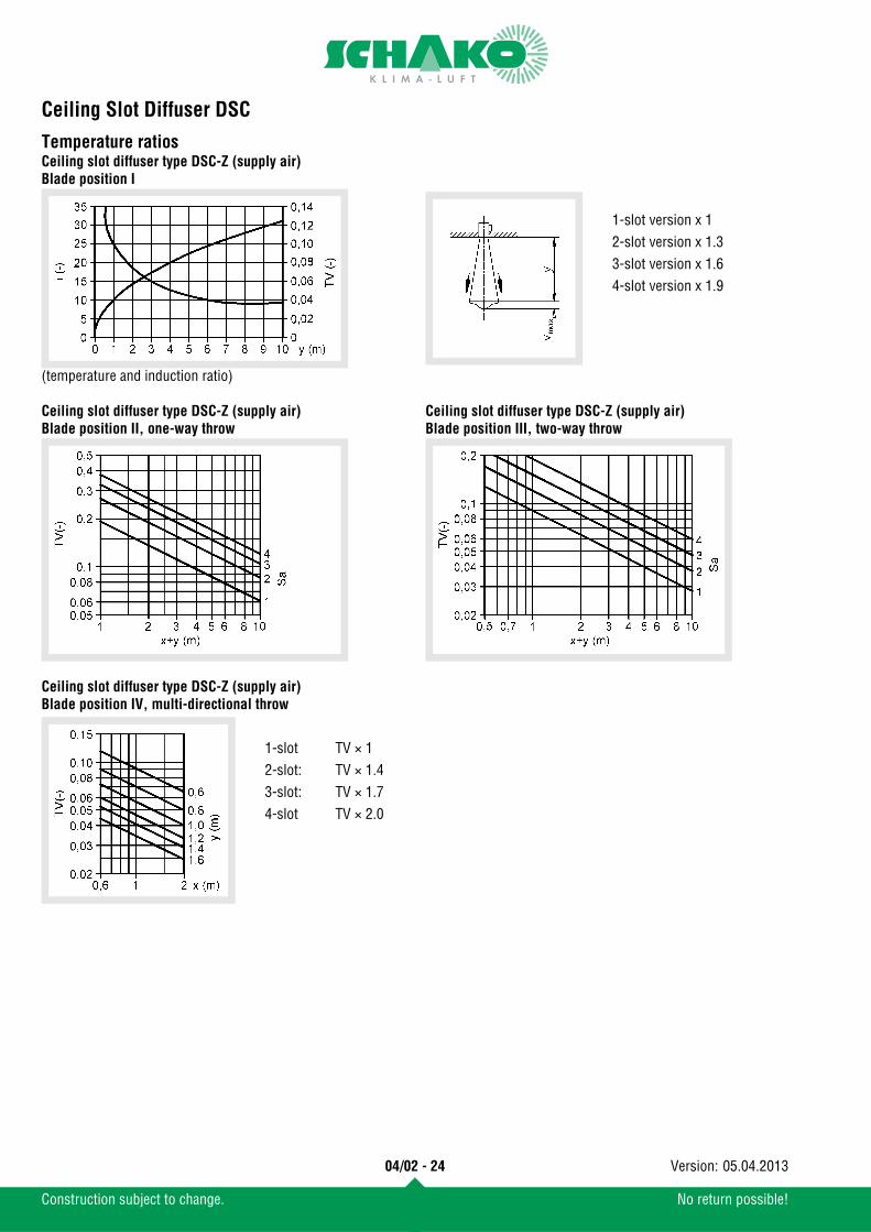
Temperature ratiosCeiling slot diffuser type DSC-Z (supply air)Blade position I
(temperature and induction ratio)
Ceiling slot diffuser type DSC-Z (supply air)Blade position II, one-way throw
Ceiling slot diffuser type DSC-Z (supply air)Blade position III, two-way throw
Ceiling slot diffuser type DSC-Z (supply air)Blade position IV, multi-directional throw
1-slot version x 12-slot version x 1.33-slot version x 1.64-slot version x 1.9
1-slot TV × 12-slot: TV × 1.43-slot: TV × 1.74-slot TV × 2.0
04/02 - 24
Construction subject to change. No return possible!
05.04.2013Version:
Ceiling Slot Diffuser DSC
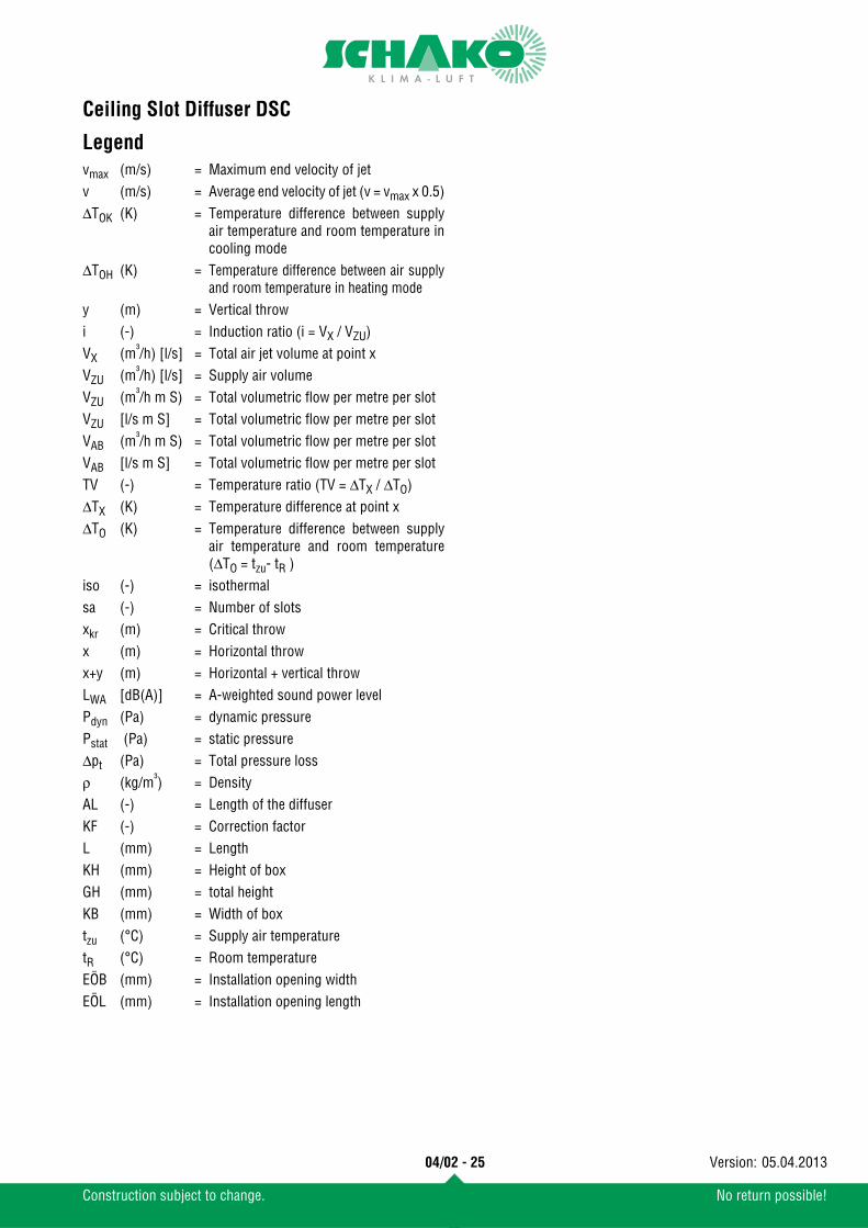
Legendvmax (m/s) = Maximum end velocity of jetv (m/s) = Average end velocity of jet (v = vmax x 0.5)ΔTOK (K) = Temperature difference between supply
air temperature and room temperature incooling mode
ΔTOH (K) = Temperature difference between air supplyand room temperature in heating mode
y (m) = Vertical throwi (-) = Induction ratio (i = VX / VZU)VX (m³/h) [l/s] = Total air jet volume at point xVZU (m³/h) [l/s] = Supply air volumeVZU (m³/h m S) = Total volumetric flow per metre per slotVZU [l/s m S] = Total volumetric flow per metre per slotVAB (m³/h m S) = Total volumetric flow per metre per slotVAB [l/s m S] = Total volumetric flow per metre per slotTV (-) = Temperature ratio (TV = ΔTX / ΔTO)ΔTX (K) = Temperature difference at point xΔTO (K) = Temperature difference between supply
air temperature and room temperature(ΔTO = tzu- tR )
iso (-) = isothermalsa (-) = Number of slotsxkr (m) = Critical throwx (m) = Horizontal throwx+y (m) = Horizontal + vertical throwLWA [dB(A)] = A-weighted sound power levelPdyn (Pa) = dynamic pressurePstat (Pa) = static pressureΔpt (Pa) = Total pressure lossρ (kg/m³) = DensityAL (-) = Length of the diffuserKF (-) = Correction factorL (mm) = LengthKH (mm) = Height of boxGH (mm) = total heightKB (mm) = Width of boxtzu (°C) = Supply air temperaturetR (°C) = Room temperatureEÖB (mm) = Installation opening widthEÖL (mm) = Installation opening length
04/02 - 25
Construction subject to change. No return possible!
05.04.2013Version:
Ceiling Slot Diffuser DSC
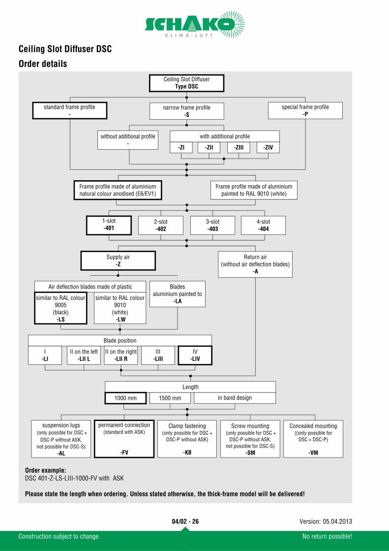
Order details
with additional profile
-ZI -ZII -ZIII
Ceiling Slot DiffuserType DSC
narrow frame profile-S
standard frame profile-
special frame profile-P
without additional profile-
Frame profile made of aluminiumnatural colour anodised (E6/EV1)
Frame profile made of aluminiumpainted to RAL 9010 (white)
Supply air-Z
Return air(without air deflection blades)
-A
Air deflection blades made of plastic
similar to RAL colour9005
(black)-LS
similar to RAL colour9010
(white) -LW
Blade position
I-LI
II on the left-LII L
II on the right-LII R
III-LIII
IV-LIV
1-slot-401
2-slot-402
3-slot-403
4-slot-404
Length
1000 mm 1500 mm in band design
Order example:DSC 401-Z-LS-LIII-1000-FV with ASK
Please state the length when ordering. Unless stated otherwise, the thick-frame model will be delivered!
permanent connection(standard with ASK)
-FV
Concealed mounting((only possible for
DSC + DSC-P)
-VM
Screw mounting (only possible for DSC +
DSC-P without ASK, not possible for DSC-S)
-SM
Bladesaluminium painted to
-LA
-ZIV
suspension lugs (only possible for DSC +
DSC-P without ASK, not possible for DSC-S)
-AL
Clamp fastening(only possible for DSC +
DSC-P without ASK)
-KB
04/02 - 26
Construction subject to change. No return possible!
05.04.2013Version:
Ceiling Slot Diffuser DSC
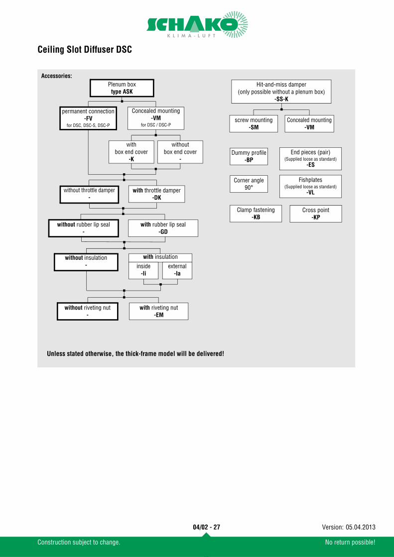
Accessories:Plenum box
type ASK
without throttle damper-
with throttle damper-DK
without rubber lip seal-
with rubber lip seal-GD
with insulation
screw mounting-SM
Concealed mounting-VM
Hit-and-miss damper(only possible without a plenum box)
-SS-K
Dummy profile-BP
Corner angle 90°
inside-Ii
external-Ia
without riveting nut-
with riveting nut-EM
without insulation-
Cross point-KP
Clamp fastening-KB
End pieces (pair)(Supplied loose as standard)
-ES
Fishplates(Supplied loose as standard)
-VL
Unless stated otherwise, the thick-frame model will be delivered!
permanent connection-FV
for DSC, DSC-S, DSC-P
Concealed mounting-VM
for DSC / DSC-P
withoutbox end cover
-
withbox end cover
-K
04/02 - 27
Construction subject to change. No return possible!
05.04.2013Version:
Ceiling Slot Diffuser DSC
Specification textsHighly inductive ceiling slot diffuser, free cross-section, resist-ance and sound power level constant in all blade positions. Framemade of extruded natural colour anodised aluminium (E6/EV1) oraluminium painted to RAL 9010 (white) and pivoting air deflec-tion blades in support profile form made of plastic (hard PVC):
Product: SCHAKO type DSC-...-Z
Fastening:
Accessories:
- similar to RAL colour 9005 (black)- similar to RAL colour 9010 (white) or - Aluminium painted to the same RAL colour as the frame pro-
file Subsequent adjustment of blades not possible.
Volumetric flows in m³/h at: 35 dB (A) 40 dB(A):DSC 401 131 156DSC 402 203 242DSC 403 234 279DSC 404 253 302
Model (number of slots)- 1-slot (-401)- 2-slot (-402)- 3-slot (-403)- 4-slot (-404)
Blade position:- LI, vertical throw- LIIL, one-way horizontal throw left- LIIR: one-way horizontal throw right- LIII, two-way horizontal throw- LIV, multi-directional throw
Length:- 1000 mm- 1500 mm- in band design
- Return air model without air deflection blades, but with black perforated plate as cover screen.Product: SCHAKO type DSC-...-A
- with narrow frame profileProduct: SCHAKO type DSC-S
- with special frame profileProduct: SCHAKO type DSC-P
Permanent connection (-FV)- Standard for versions DSC, DSC-S and DSC-P with ASK
for complete mounting of plenum box and slot diffuserClamp fastening (-KB)
- possible for versions DSC and DSC-P without plenum box ASK- not possible for version DSC-S
Screw mounting (-SM)- possible for versions DSC and DSC-P without plenum box,
screws on site- not possible for version DSC-S
Concealed mounting (-VM)- possible for versions DSC and DSC-P- not possible for version DSC-S
suspension lugs (-AL)- possible for versions DSC and DSC-P without plenum box ASK- not possible for version DSC-S
- with plenum box (-ASK) made of galvanised sheet steel and lateral connection piece and fixing lugs.- with a throttle damper (-DK) adjustable from the front in
the plenum box for air volume regulation- with rubber lip seal (-GD)- with thermal insulation
- internal (-Ii)- external (-Ia)
- with riveting nuts (M4) for suspension (-EM)- with permanent connection (-FV, standard)- with concealed mounting (-VM)
- with box end cover (-K) (pair) (supplied loose)
- with end pieces (-ES) (pair) (supplied loose as standard)
- with fishplates (-VL) (supplied loose as standard)
- with corner angles 90° (-EW)
- with cross point (-KP)
- with additional profile (for DSC-S)- Z I (-Z I), connection of ceiling panels- Z II (-Z II), connection of the panelled ceilings.- Z III (-Z III), connection of ceiling panels.- Z V (-Z V), connection of the lighting ceiling.
- with hit-and-miss damper (-SS-K), only possible without a ple-num box.
04/02 - 28
Construction subject to change. No return possible!
05.04.2013Version:
Ceiling Slot Diffuser DSC
- concealed mounting (-VM, standard for DSC-S with/with-out additional profile)
- screw mounting (-SM, Standard for DSC and DSC-P)
- with dummy profile (-BP)
04/02 - 29
Construction subject to change. No return possible!
05.04.2013Version:


![Supreme 2 In-Ceiling Motorized Screens Slot Opening · Motorized Screens In-Ceiling Supreme 2 In-Ceiling Motorized Screens Slot Opening [1] Technical Product Information Screen Fabric](https://img.pdfslide.us/doc/110x75/5b7719517f8b9a47518c4686/supreme-2-in-ceiling-motorized-screens-slot-motorized-screens-in-ceiling-supreme.jpg)