Embed Size (px)
Citation preview
CEG 3185
Tutorial 5 Modem(The Matlab scripts were originally developed by Xiaohong Liu)
(The slides are prepared by Lei Chen)
TUT 5 MODEMTUT 5 MODEM
• Contents
Introduction to Communication Systems
Analog ModulationAmplitude Modulation (AM), Frequency Modulation (FM), and Phase Modulation (PM)
Digital Communication TechniquesAmplitude Shift Keying (ASK), Frequency Shift Keying (FSK), Phase Shift Keying (PSK) -- Quadrature Phase Shift Keying (QPSK)
Lab 5 QPSK Modulation and Demodulation
Introduction to Modulation and Introduction to Modulation and DemodulationDemodulation
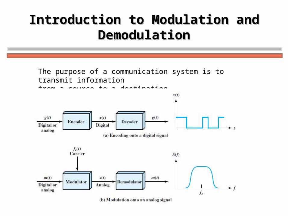
The purpose of a communication system is to transmit information from a source to a destination.
What is Modulation?What is Modulation?
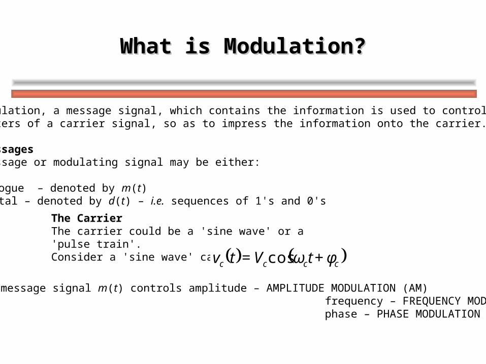
In modulation, a message signal, which contains the information is used to control the parameters of a carrier signal, so as to impress the information onto the carrier.
The MessagesThe message or modulating signal may be either:
Analogue – denoted by m(t) Digital – denoted by d(t) – i.e. sequences of 1's and 0's
The CarrierThe carrier could be a 'sine wave' or a 'pulse train'. Consider a 'sine wave' carrier: cccc φ+tωV=tv cos
If the message signal m(t) controls amplitude – AMPLITUDE MODULATION (AM) frequency – FREQUENCY MODULATION (FM) phase – PHASE MODULATION (PM)
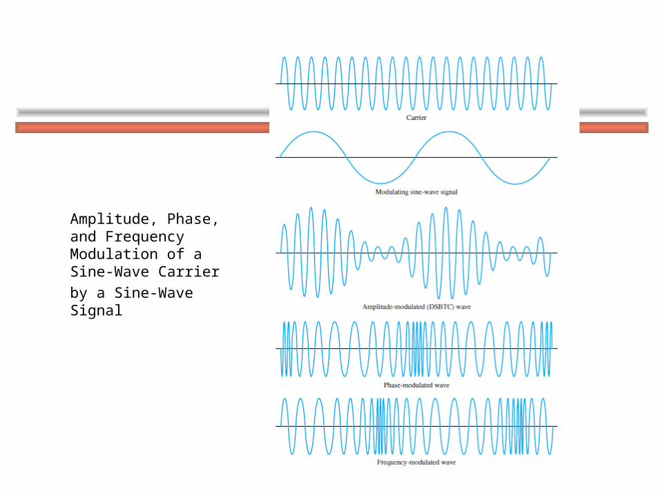
Amplitude, Phase, and Frequency Modulation of a Sine-Wave Carrier
by a Sine-Wave Signal
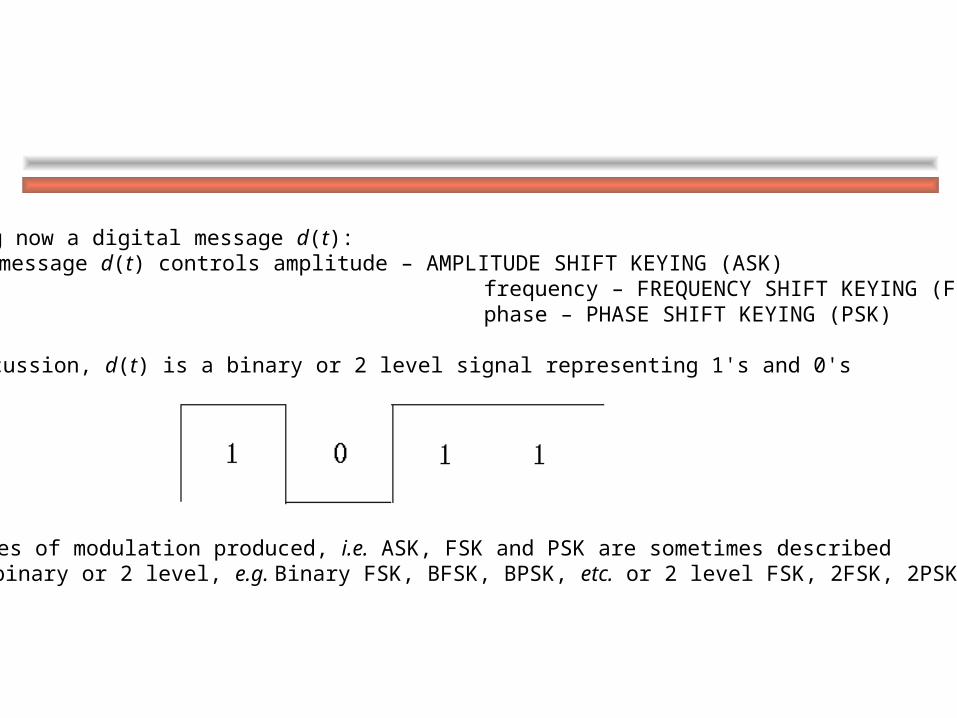
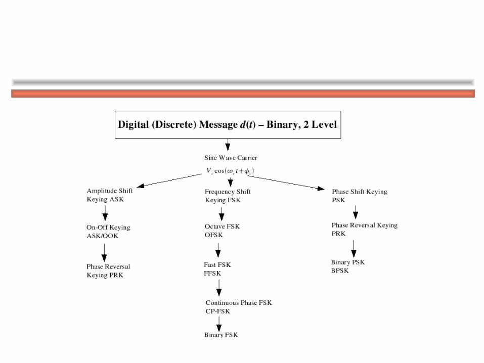
Considering now a digital message d(t): If the message d(t) controls amplitude – AMPLITUDE SHIFT KEYING (ASK) frequency – FREQUENCY SHIFT KEYING (FSK) phase – PHASE SHIFT KEYING (PSK)
In this discussion, d(t) is a binary or 2 level signal representing 1's and 0's
The types of modulation produced, i.e. ASK, FSK and PSK are sometimes described as binary or 2 level, e.g. Binary FSK, BFSK, BPSK, etc. or 2 level FSK, 2FSK, 2PSK etc.
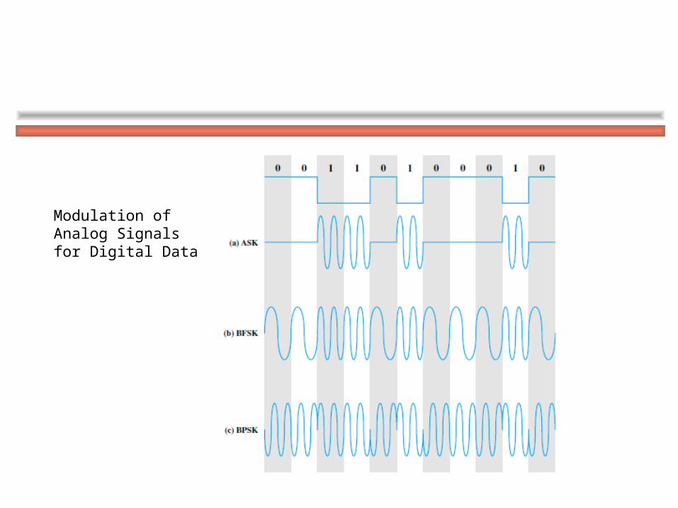
Modulation of Analog Signals for Digital Data
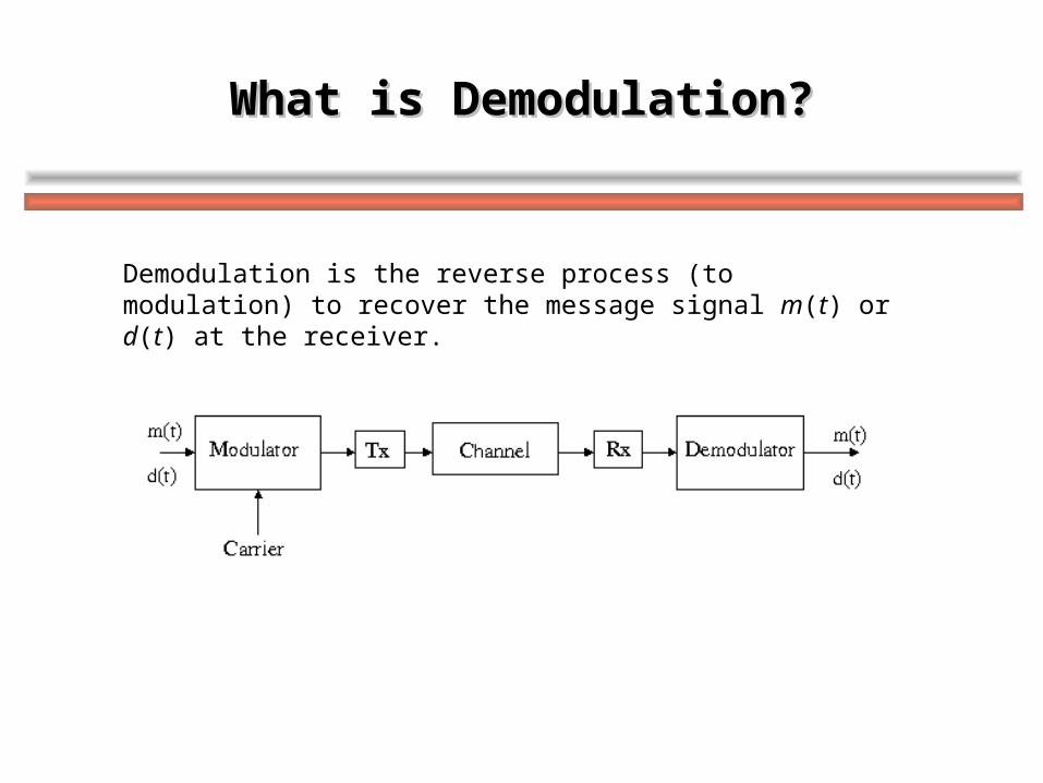
What is Demodulation?What is Demodulation?
Demodulation is the reverse process (to modulation) to recover the message signal m(t) or d(t) at the receiver.
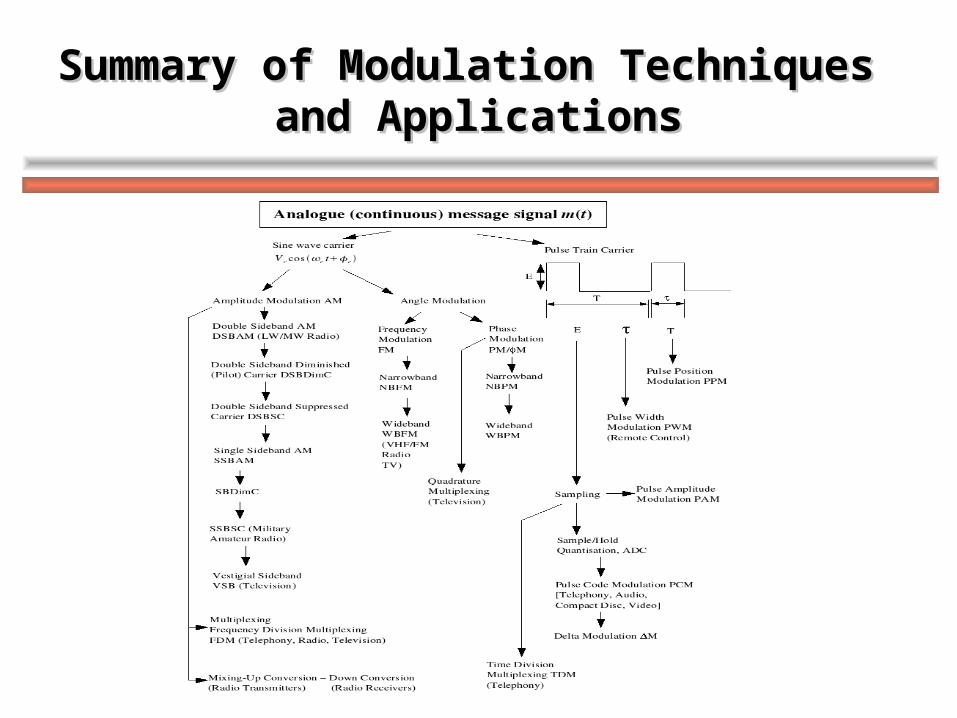
Summary of Modulation Techniques Summary of Modulation Techniques and Applicationsand Applications
Lab 5 QPSK Modulation and DemodulationLab 5 QPSK Modulation and Demodulation
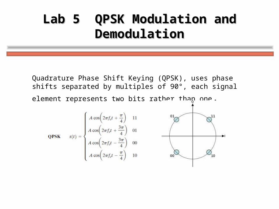
Quadrature Phase Shift Keying (QPSK), uses phase shifts separated by
multiples of 90°, each signal element represents two bits rather than one.
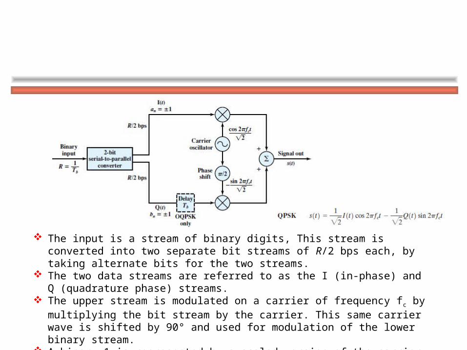
The input is a stream of binary digits, This stream is converted into two separate bit streams of R/2 bps each, by taking alternate bits for the two streams.
The two data streams are referred to as the I (in-phase) and Q (quadrature phase) streams. The upper stream is modulated on a carrier of frequency fc by multiplying the bit stream by
the carrier. This same carrier wave is shifted by 90° and used for modulation of the lower binary stream.
A binary 1 is represented by a scaled version of the carrier wave and a binary 0 is represented by a scaled version of the negative of the carrier wave, both at a constant amplitude.
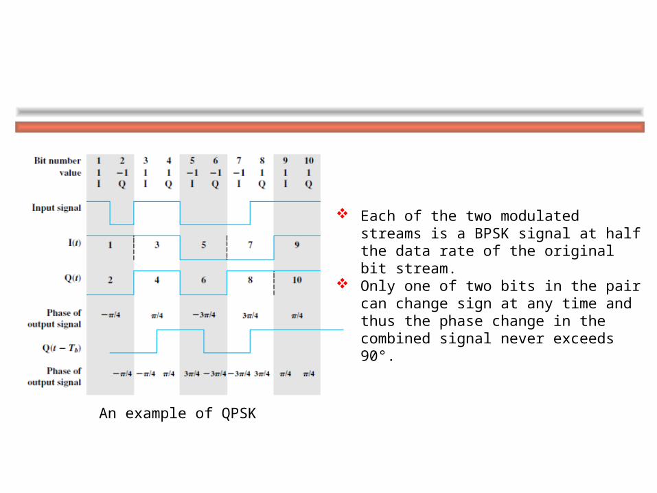
An example of QPSK
Each of the two modulated streams is a BPSK signal at half the data rate of the original bit stream.
Only one of two bits in the pair can change sign at any time and thus the phase change in the combined signal never exceeds 90°.
Lab 5 QPSK Modulation and DemodulationLab 5 QPSK Modulation and Demodulation
Lab Objective:
To get familiar with signal modulation and demodulation;
To master QPSK modulation and demodulation;
To better understand signal encoding and decoding techniques.
Lab 5 QPSK Modulation and DemodulationLab 5 QPSK Modulation and Demodulation
Lab Task
Task A: QPSK Modulation
The two data streams I (in-phase) and Q (quadrature phase) are simulated with sin waves. The I stream is modulated on a carrier of frequency fc by multiplying the bit stream by the carrier x(t)=0.5+0.5*cos(pi*f). This same carrier wave is shifted by 90°and used for modulation of Q stream.
Use QPSK modulation to get the synthesis sequence: QPSK=sqrt(1/2).*I +sqrt(1/2).*Q.
Then add random noise on the synthesis signal.
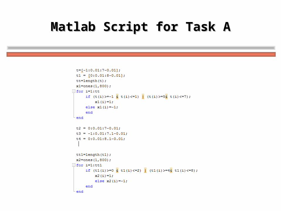
Matlab Script for Task AMatlab Script for Task A
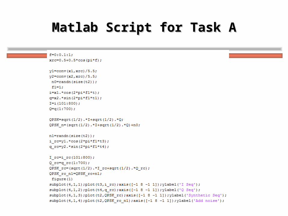
Matlab Script for Task AMatlab Script for Task A
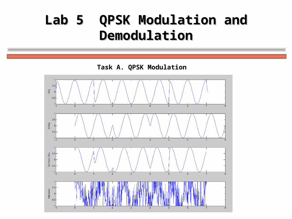
Lab 5 QPSK Modulation and DemodulationLab 5 QPSK Modulation and Demodulation
Task A. QPSK Modulation
Lab 5 QPSK Modulation and DemodulationLab 5 QPSK Modulation and Demodulation
Task B: QPSK Demodulation
Demodulation is the reverse process (to modulation) to recover the I and Q sequences at the receiver.
Demodulate the synthesis signal with sin waves, respectively:
I=QPSK.*cos(2*pi*f*t);
Q=QPSK.*sin(2*pi*f*t) ;
Then recover the original data sequences from the I and Q sequences.
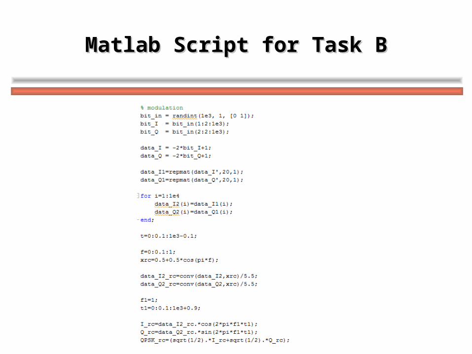
Matlab Script for Task BMatlab Script for Task B
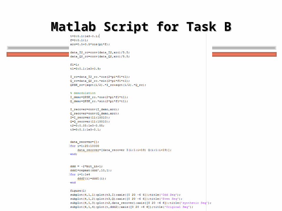
Matlab Script for Task BMatlab Script for Task B
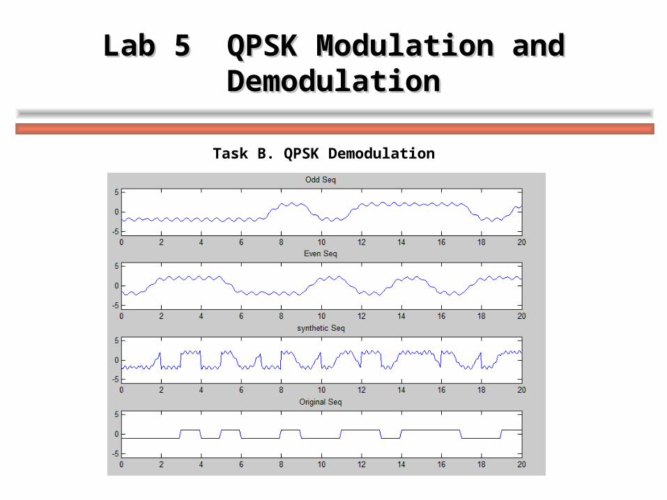
Lab 5 QPSK Modulation and DemodulationLab 5 QPSK Modulation and Demodulation
Task B. QPSK Demodulation

Thank you !Thank you !