Embed Size (px)
Citation preview
NIST Technical Note 1778
Exposing Wood Decking Assemblies to
Continuous Wind-Driven Firebrand Showers
Samuel L. Manzello Sayaka Suzuki
http://dx.doi.org/10.6028/NIST.TN.1778
NIST Technical Note 1778
Exposing Wood Decking Assemblies to
Continuous Wind-Driven Firebrand Showers
Samuel L. Manzello
Sayaka Suzuki Fire Research Division
Engineering Laboratory
http://dx.doi.org/10.6028/NIST.TN.1778
December, 2012
U.S. Department of Commerce Rebecca Blank, Acting Secretary
National Institute of Standards and Technology
Patrick D. Gallagher, Under Secretary of Commerce for Standards and Technology and Director
ii
Certain commercial entities, equipment, or materials may be identified in this
document in order to describe an experimental procedure or concept adequately. Such identification is not intended to imply recommendation or endorsement by the National Institute of Standards and Technology, nor is it intended to imply that the
entities, materials, or equipment are necessarily the best available for the purpose.
National Institute of Standards and Technology Technical Note 1778 Natl. Inst. Stand. Technol. Tech. Note 1778, 20 pages (December, 2012)
http://dx.doi.org/10.6028/NIST.TN.1778 CODEN: NTNOEF
iii
Table of Contents
page
Abstract iv
1.0 Introduction 1
2.0 Experimental Description 3
3.0 Results and Discussion 9
4.0 Summary 17
5.0 Acknowledgments 17
6.0 References 17
iv
Abstract
A series of experiments were conducted to examine potential vulnerabilities of wood decks to continuous, wind-driven firebrand showers. Sections of wood decks (1.2 m by 1.2 m) were constructed and attached to a re-entrant corner assembly. The deck/reentrant corner assembly was then exposed to continuous, wind-driven firebrand bombardment generated by the newly developed NIST full-scale Continuous Feed Firebrand Generator (NIST full-scale Continuous Feed Dragon) installed in the Building Research Institute’s (BRI) Fire Research Wind Tunnel Facility (FRWTF). The type of wood decks used, as well as the placement within a reentrant corner assembly, was based on input received from a decking ignition vulnerability workshop that NIST held in California in 2011. Three different wood decks types were exposed to wind-driven firebrand showers at wind speeds of 6 m/s; Cedar, Douglas-Fir, and Redwood. For each wood deck tested (exposed to a total firebrand mass flux of 17.1 g/m2s), firebrands were observed to accumulate on the deck surface, and due to continual glowing firebrand bombardment, each wood deck type was observed to ignite by flaming ignition. The average time to flaming ignition was 437 s for Cedar, 934 s for Douglas-Fir, and 756 s for Redwood. Therefore, wood decks were observed to be vulnerable to ignition from continuous, wind-driven firebrand showers. Results of these experiments are discussed in detail.
1
1.0 Introduction
Wildland-Urban Interface (WUI) fires have caused significant destruction to communities in Australia, Greece, Portugal, Spain, and the USA [1]. There have been three significant WUI fires in California over the past six years. The 2003 Cedar Fire in California resulted in $2B in insured losses and destroyed more than three thousand homes [1]. The 2007 Southern California Fire displaced more than 300,000 people, destroyed over one thousand structures, and resulted in $1B paid by insurers in 2007 alone [2]. WUI fires continue to burn in the USA; most recently in Texas in 2011 and Colorado and California in 2012. In 2009, fires in Victoria, Australia caused the death of more than 150 people, destroying more than two thousand structures.
From a pragmatic point of view, the WUI fire problem can be seen as a structure ignition
problem [1]. Ignition resistant structures under WUI fire exposure was listed as one of the major recommendations in the USA GAO 2005 report, Technology Assessment: Protecting Structures and Improving Communications During Wildland Fires [3], and was the subject of a Homeland Security Presidential Directive [4]. In spite of these facts, little effort has been spent on understanding the processes of structure ignition in these fires.
As both vegetation and structures burn in WUI fires, pieces of burning material, known as
firebrands, are generated, become lofted, and are transported by the wind. This results in showers of wind-driven firebrands. Post-fire studies indicate that firebrand showers have a significant role in the spread of disastrous WUI fires [4-9]. Interestingly, post-fire damage studies have suggested for some time that firebrands are a significant cause of structure ignition in WUI fires, yet for over 40 years, firebrand studies have focused on understanding how far firebrands fly, known as spotting distance [10-21]. Few studies have examined firebrand generation [22–24] and the ultimate ignition of materials by firebrands [25–28]. For these reasons, the prior firebrand studies are of limited help in designing firebrand resistant structures.
Scientifically based building codes and standards are needed to guide construction of new
structures in areas known to be prone to these fires in order to reduce the risk of structural ignition in the event of a firebrand attack. Proven, scientifically based retrofitting strategies are required for homes located in areas prone to such fires. To meet these objectives requires knowledge regarding the types of materials that can be ignited by firebrands as well as vulnerable points on a structure where firebrands may easily enter. The reason that prior firebrand investigations have not been able to quantify the vulnerabilities of structures to ignition from firebrand showers is that it is difficult to develop a measurement method to replicate wind- driven firebrand bombardment on structures that occur in actual WUI. Entirely new experimental approaches are required to address this problem. To address this problem, a new firebrand research area targeted on quantifying structure vulnerabilities to wind-driven firebrand showers has been developed by NIST. This type of firebrand research is now possible due to the development of the Firebrand Generator.
A unique experimental apparatus, known as the NIST Firebrand Generator (NIST Dragon),
has been constructed to generate controlled, repeatable firebrand showers commensurate with those measured from burning conifers and a real WUI fire. The purpose of the NIST Dragon is to simulate wind-driven firebrand showers observed in long-range spotting; therefore, glowing
2
firebrands were the initial emphasis. Yet, due to careful design of the NIST Dragon, it is also possible to generate flaming firebrand showers. Another very important characteristic of the NIST Dragon is that the firebrand size and mass produced using the device can be tailored to those measured from full-scale tree burns and actual WUI fires, which are in stark contrast with the size of firebrands referenced in existing test standards and wildfire protection building construction recommendations [29]. In collaboration with the California Department of Forestry and Fire Protection (CALFIRE), NIST has quantified firebrand distributions from a real WUI fire (Angora Fire) for the first time [29]; more information such as this is needed.
Since wind plays a critical role in the spread of WUI fires, NIST has established collaboration with the Building Research Institute (BRI) in Japan. BRI maintains one of the only full-scale wind tunnel facilities in the world designed specifically for fire experimentation, the Fire Research Wind Tunnel Facility (FRWTF). BRI’s FRWTF, constructed in the late 1990s, is one of the first wind tunnel facilities in the world designed specifically with fire experiments in mind. Parametric studies have been conducted using the NIST Dragon installed in BRI’s FRWTF to expose roofing assemblies, building vents, siding treatments, walls fitted with eaves, and glazing assemblies to wind-driven firebrand showers [30-35]. In addition, the dangers of firebrand accumulation in front of structures have been quantified for the first time. It is worth noting that NIST Dragon has now been reproduced by other research laboratories. For example, the Insurance Institute for Business and Home Safety (IBHS) has used the NIST Dragon concept to generate firebrand showers in their full-scale wind tunnel facility [36].
In WUI fires, decking assemblies have been observed to be an ignition vulnerability based on post-fire damage surveys. The Office of the State Fire Marshall (OFSM) in California adopted the test method known as State Fire Marshall (SFM) STANDARD 12-7A-4 [37]. The SFM test method is intended to determine the response of decks to firebrand exposure and the firebrand exposure is very similar to the ASTM E108 [38] roofing test. ASTM E108 has been used for more than 100 years. Namely, a firebrand is simulated by placing a burning wood crib (either Class A, Class B, or Class C firebrand) on top of a section of a deck assembly under an air flow. This test standard does not adequately simulate the processes and conditions observed in real Wildland-Urban Interface (WUI) fires. The dynamic process of multiple firebrands bombarding decking materials as a function of time is not taken into account in this standard. Firebrand showers have been observed in actual WUI fires over and over again [1]. Based on firebrand attack from real WUI fires, it is expected that multiple firebrands would accumulate within gaps/crevices of decking materials. In addition to not simulating a dynamic firebrand attack, no attempt is made to relate the size and mass of the firebrand used in this standard to actual firebrands produced from burning vegetation and structures. There is no evidence to suggest that this test is a ‘worst-case’ firebrand exposure for decking assemblies.
To this end, a series of experiments were conducted to examine possible vulnerabilities of
wood decks to continuous, wind-driven firebrand showers. Sections of wood decks (1.2 m by 1.2 m) were constructed and attached to a reentrant corner assembly. The deck/reentrant corner assembly was then exposed to continuous, wind-driven firebrand bombardment generated by the recently developed NIST full-scale Continuous Feed Firebrand Generator (aka the NIST full-scale Continuous Feed Dragon) installed in the FRWTF. While previously the full-scale NIST Dragon (Batch Feed) coupled to BRI’s FRWTF has been used to expose building elements to
3
firebrand showers, the duration of exposure using the existing apparatus is limited. To develop test methods needed to evaluate different building materials resistance to firebrand showers requires the capability to generate firebrand showers of varying duration. Therefore, a new full-scale Continuous Feed Firebrand Generator was developed in support of these decking assembly experiments.
The type of wood decks used, as well as the placement within a reentrant corner assembly, was based on input received from a decking workshop NIST held in California in 2011 [39]. The Los Angeles (LA) Basin Chapter of the International Code Council (ICC; http://www.iccsafe.org) hosted a workshop on June 15, 2011 in Norwalk, CA. The workshop was moderated by Mr. Ruben Grijalva, former CALFIRE director and Mr. Stuart Tom, Certified Building Official (C.B.O.) from the city of Glendale, CA, served as the official note taker. Mr. Neville Pereira, LA Basin ICC Chapter President, arranged the venue and location. At that workshop, input was obtained for this experimental series from interested parties in California (e.g. building officials, Office of the State Fire Marshall (OFSM), code consultants, construction industry, and product manufacturers) since large WUI fires have occurred in this state recently. Specifically, guidance was desired in order to conduct experiments that will have the potential to provide the scientific basis for improvements of existing codes and development of new codes. The results of the decking workshop form the basis for this study. 2.0 Experimental Description
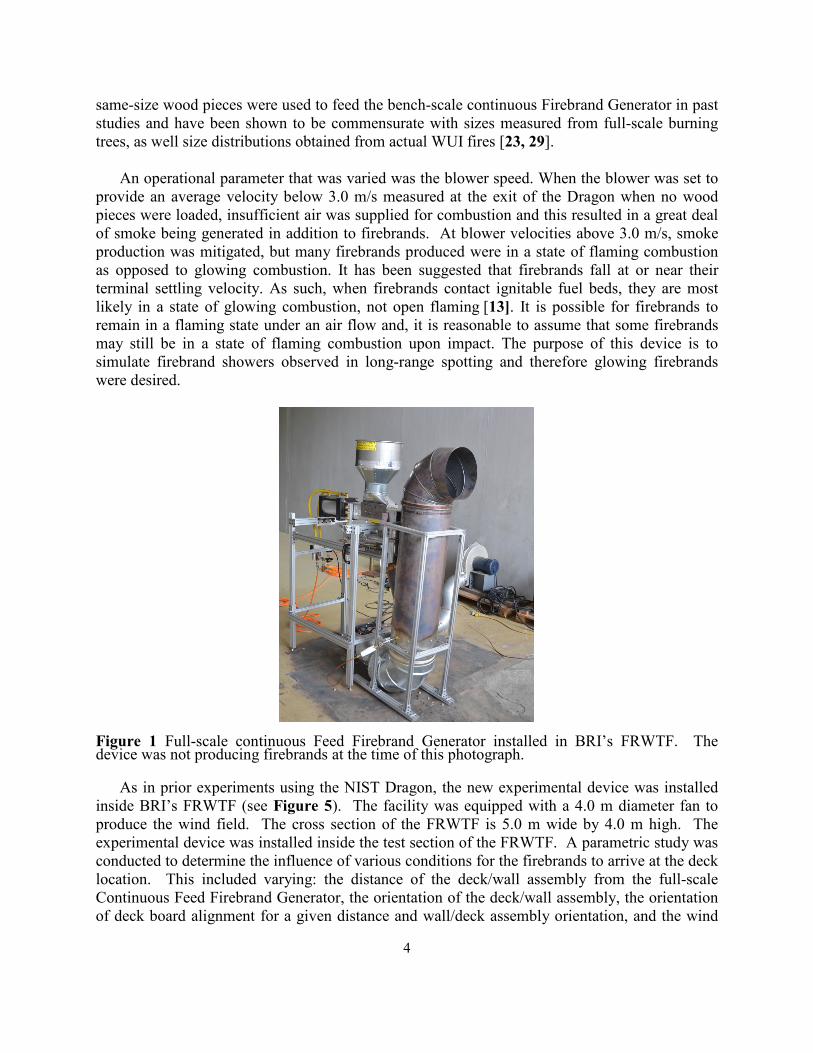
Figure 1 is a photograph of the new full-scale Continuous Feed Firebrand Generator. This version of the device is modified from the NIST Dragon [30-35] and consists of two parts: the main body and continuous feeding component. The feeding system was connected to the main body and was equipped with two gates to prevent fire spread (described in more detail below). Each gate was alternatively opened and closed. A blower was connected to the main body and the purpose of the blower is also described below. All components of the full-scale Continuous Feed Firebrand Generator were constructed of stainless steel. A major challenge when constructing this device was designing a completely contained feeding system shielded from the wind tunnel flow.
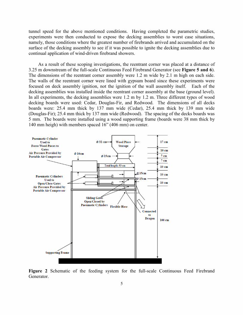
The feeding system consisted of a pneumatic cylinder coupled to a cylindrical container
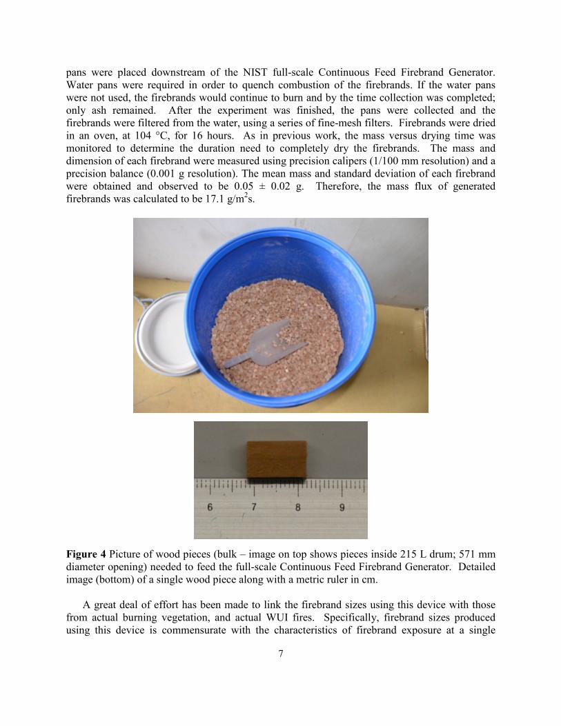
where wood pieces were stored (see Figure 2). The pneumatic cylinder was contained inside a metal sleeve. Inside the metal sleeve, the sliding rod of the pneumatic cylinder was connected to a plate that allowed the volume of wood contained within the sleeve to be varied. This volume was set precisely to allow a specific mass of firebrands to fall into this volume. When the air pressure was applied, the sliding rod of the pneumatic cylinder moved forward, forcing the wood pieces within the volume of the metal sleeve to the first gate, where they are then dropped into the second gate that leads to the Dragon where they are ignited (see Figure 3). Care was taken to select the pneumatic cylinder (15 cm bore with 15 cm stroke; maximum pressure of 1.7 MPa and maximum load of 31 kN); smaller sized pneumatic cylinders were observed to be unable to force the wood pieces to the first gate and would jam. The gate system was required to contain the fire from spreading from the Dragon to the feed system and each gate was driven by pneumatic cylinders as well. For all tests, Douglas-fir wood pieces machined to dimensions of 7.9 mm (H) by 7.9 mm (W) by 12.7 mm (L) were used to produce firebrands (see Figure 4). The
4
same-size wood pieces were used to feed the bench-scale continuous Firebrand Generator in past studies and have been shown to be commensurate with sizes measured from full-scale burning trees, as well size distributions obtained from actual WUI fires [23, 29].
An operational parameter that was varied was the blower speed. When the blower was set to
provide an average velocity below 3.0 m/s measured at the exit of the Dragon when no wood pieces were loaded, insufficient air was supplied for combustion and this resulted in a great deal of smoke being generated in addition to firebrands. At blower velocities above 3.0 m/s, smoke production was mitigated, but many firebrands produced were in a state of flaming combustion as opposed to glowing combustion. It has been suggested that firebrands fall at or near their terminal settling velocity. As such, when firebrands contact ignitable fuel beds, they are most likely in a state of glowing combustion, not open flaming [13]. It is possible for firebrands to remain in a flaming state under an air flow and, it is reasonable to assume that some firebrands may still be in a state of flaming combustion upon impact. The purpose of this device is to simulate firebrand showers observed in long-range spotting and therefore glowing firebrands were desired.
Figure 1 Full-scale continuous Feed Firebrand Generator installed in BRI’s FRWTF. The device was not producing firebrands at the time of this photograph.
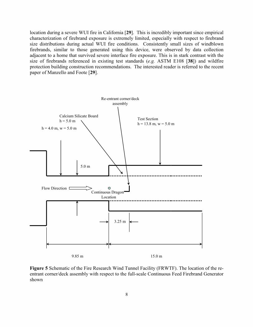
As in prior experiments using the NIST Dragon, the new experimental device was installed inside BRI’s FRWTF (see Figure 5). The facility was equipped with a 4.0 m diameter fan to produce the wind field. The cross section of the FRWTF is 5.0 m wide by 4.0 m high. The experimental device was installed inside the test section of the FRWTF. A parametric study was conducted to determine the influence of various conditions for the firebrands to arrive at the deck location. This included varying: the distance of the deck/wall assembly from the full-scale Continuous Feed Firebrand Generator, the orientation of the deck/wall assembly, the orientation of deck board alignment for a given distance and wall/deck assembly orientation, and the wind
5
tunnel speed for the above mentioned conditions. Having completed the parametric studies, experiments were then conducted to expose the decking assemblies to worst case situations, namely, those conditions where the greatest number of firebrands arrived and accumulated on the surface of the decking assembly to see if it was possible to ignite the decking assemblies due to continual application of wind-driven firebrand showers.
As a result of these scoping investigations, the reentrant corner was placed at a distance of
3.25 m downstream of the full-scale Continuous Feed Firebrand Generator (see Figure 5 and 6). The dimensions of the reentrant corner assembly were 1.2 m wide by 2.1 m high on each side. The walls of the reentrant corner were lined with gypsum board since these experiments were focused on deck assembly ignition, not the ignition of the wall assembly itself. Each of the decking assemblies was installed inside the reentrant corner assembly at the base (ground level). In all experiments, the decking assemblies were 1.2 m by 1.2 m. Three different types of wood decking boards were used: Cedar, Douglas-Fir, and Redwood. The dimensions of all decks boards were: 25.4 mm thick by 137 mm wide (Cedar), 25.4 mm thick by 139 mm wide (Douglas-Fir); 25.4 mm thick by 137 mm wide (Redwood). The spacing of the decks boards was 5 mm. The boards were installed using a wood supporting frame (boards were 38 mm thick by 140 mm heigh) with members spaced 16” (406 mm) on center.
Figure 2 Schematic of the feeding system for the full-scale Continuous Feed Firebrand Generator.
6
A typical experiment was conducted in the following manner. The deck assembly was installed inside the reentrant corner. The wind tunnel speed was set to the desired level (e.g. 6 m/s). Wood pieces were first loaded into the cylinder storage container and the air compressor needed to provide compressed air for the pneumatic cylinder and gate system was switched on (air compressor pressure was set to 0.7 MPa). The blower was set at 3.0 m/s and two propane burners were ignited and inserted into the side of the device. The propane burners were operated continuously during the experiment. The pneumatic piston was then activated and the sliding rod was positioned to allow wood pieces to enter the volume in the metal sleeve. The sliding rod was moved to push the wood pieces (200g) to the first gate. The gate was opened, closed, and the second gate was then opened, and the wood fell into the Dragon. The feeding was varied to determine the optimal conditions for continuous firebrand showers. It was observed that 200g, fed into the Dragon every 15 sec provided an adequate firebrand generation rate to ignite building materials. For completeness, 200 g corresponded to approximately 400 wood pieces deposited every 15 sec.
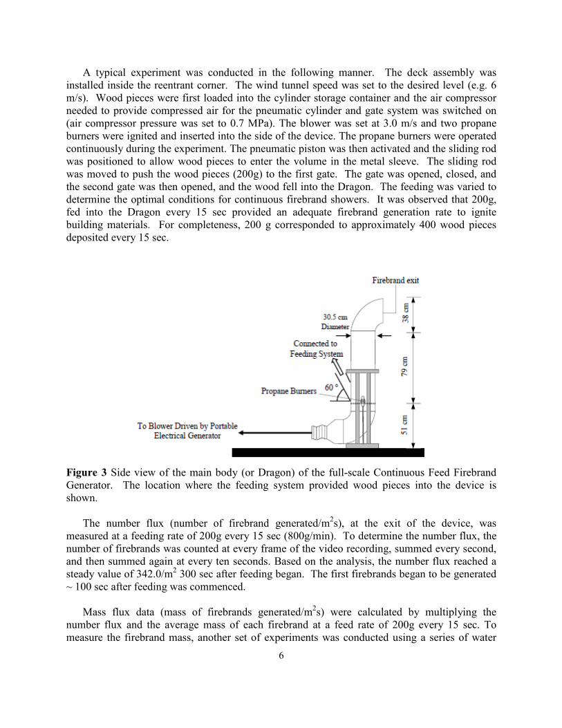
Figure 3 Side view of the main body (or Dragon) of the full-scale Continuous Feed Firebrand Generator. The location where the feeding system provided wood pieces into the device is shown.
The number flux (number of firebrand generated/m2s), at the exit of the device, was
measured at a feeding rate of 200g every 15 sec (800g/min). To determine the number flux, the number of firebrands was counted at every frame of the video recording, summed every second, and then summed again at every ten seconds. Based on the analysis, the number flux reached a steady value of 342.0/m2 300 sec after feeding began. The first firebrands began to be generated ~ 100 sec after feeding was commenced.
Mass flux data (mass of firebrands generated/m2s) were calculated by multiplying the
number flux and the average mass of each firebrand at a feed rate of 200g every 15 sec. To measure the firebrand mass, another set of experiments was conducted using a series of water
7
pans were placed downstream of the NIST full-scale Continuous Feed Firebrand Generator. Water pans were required in order to quench combustion of the firebrands. If the water pans were not used, the firebrands would continue to burn and by the time collection was completed; only ash remained. After the experiment was finished, the pans were collected and the firebrands were filtered from the water, using a series of fine-mesh filters. Firebrands were dried in an oven, at 104 °C, for 16 hours. As in previous work, the mass versus drying time was monitored to determine the duration need to completely dry the firebrands. The mass and dimension of each firebrand were measured using precision calipers (1/100 mm resolution) and a precision balance (0.001 g resolution). The mean mass and standard deviation of each firebrand were obtained and observed to be 0.05 ± 0.02 g. Therefore, the mass flux of generated firebrands was calculated to be 17.1 g/m2s.
Figure 4 Picture of wood pieces (bulk – image on top shows pieces inside 215 L drum; 571 mm diameter opening) needed to feed the full-scale Continuous Feed Firebrand Generator. Detailed image (bottom) of a single wood piece along with a metric ruler in cm.
A great deal of effort has been made to link the firebrand sizes using this device with those
from actual burning vegetation, and actual WUI fires. Specifically, firebrand sizes produced using this device is commensurate with the characteristics of firebrand exposure at a single
8
location during a severe WUI fire in California [29]. This is incredibly important since empirical characterization of firebrand exposure is extremely limited, especially with respect to firebrand size distributions during actual WUI fire conditions. Consistently small sizes of windblown firebrands, similar to those generated using this device, were observed by data collection adjacent to a home that survived severe interface fire exposure. This is in stark contrast with the size of firebrands referenced in existing test standards (e.g. ASTM E108 [38]) and wildfire protection building construction recommendations. The interested reader is referred to the recent paper of Manzello and Foote [29].
Figure 5 Schematic of the Fire Research Wind Tunnel Facility (FRWTF). The location of the re-entrant corner/deck assembly with respect to the full-scale Continuous Feed Firebrand Generator shown
9.85 m
Calcium Silicate Board h = 5.0 m
15.0 m
5.0 m
Continuous Dragon Location
3.25 m
Flow Direction
Test Section h = 13.8 m, w = 5.0 m
h = 4.0 m, w = 5.0 m
Re-entrant corner/deck assembly
9
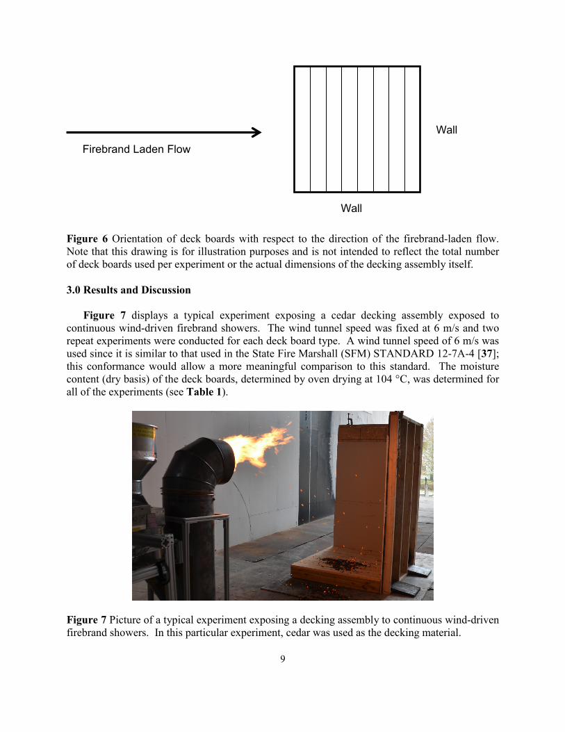
Figure 6 Orientation of deck boards with respect to the direction of the firebrand-laden flow. Note that this drawing is for illustration purposes and is not intended to reflect the total number of deck boards used per experiment or the actual dimensions of the decking assembly itself. 3.0 Results and Discussion
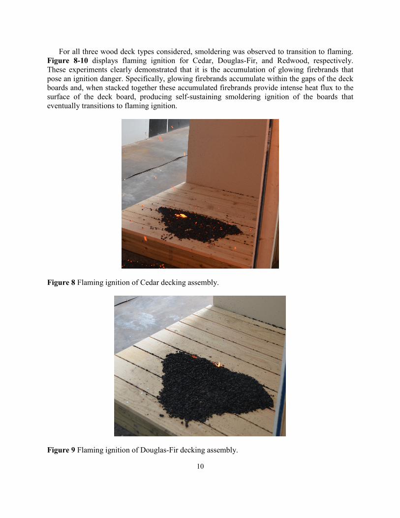
Figure 7 displays a typical experiment exposing a cedar decking assembly exposed to continuous wind-driven firebrand showers. The wind tunnel speed was fixed at 6 m/s and two repeat experiments were conducted for each deck board type. A wind tunnel speed of 6 m/s was used since it is similar to that used in the State Fire Marshall (SFM) STANDARD 12-7A-4 [37]; this conformance would allow a more meaningful comparison to this standard. The moisture content (dry basis) of the deck boards, determined by oven drying at 104 °C, was determined for all of the experiments (see Table 1).
Figure 7 Picture of a typical experiment exposing a decking assembly to continuous wind-driven firebrand showers. In this particular experiment, cedar was used as the decking material.
Firebrand Laden Flow
Wall
Wall
10
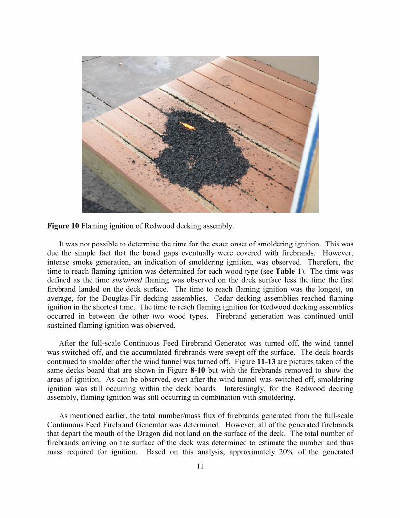
For all three wood deck types considered, smoldering was observed to transition to flaming. Figure 8-10 displays flaming ignition for Cedar, Douglas-Fir, and Redwood, respectively. These experiments clearly demonstrated that it is the accumulation of glowing firebrands that pose an ignition danger. Specifically, glowing firebrands accumulate within the gaps of the deck boards and, when stacked together these accumulated firebrands provide intense heat flux to the surface of the deck board, producing self-sustaining smoldering ignition of the boards that eventually transitions to flaming ignition.
Figure 8 Flaming ignition of Cedar decking assembly.
Figure 9 Flaming ignition of Douglas-Fir decking assembly.
11
Figure 10 Flaming ignition of Redwood decking assembly.
It was not possible to determine the time for the exact onset of smoldering ignition. This was due the simple fact that the board gaps eventually were covered with firebrands. However, intense smoke generation, an indication of smoldering ignition, was observed. Therefore, the time to reach flaming ignition was determined for each wood type (see Table 1). The time was defined as the time sustained flaming was observed on the deck surface less the time the first firebrand landed on the deck surface. The time to reach flaming ignition was the longest, on average, for the Douglas-Fir decking assemblies. Cedar decking assemblies reached flaming ignition in the shortest time. The time to reach flaming ignition for Redwood decking assemblies occurred in between the other two wood types. Firebrand generation was continued until sustained flaming ignition was observed.
After the full-scale Continuous Feed Firebrand Generator was turned off, the wind tunnel
was switched off, and the accumulated firebrands were swept off the surface. The deck boards continued to smolder after the wind tunnel was turned off. Figure 11-13 are pictures taken of the same decks board that are shown in Figure 8-10 but with the firebrands removed to show the areas of ignition. As can be observed, even after the wind tunnel was switched off, smoldering ignition was still occurring within the deck boards. Interestingly, for the Redwood decking assembly, flaming ignition was still occurring in combination with smoldering.
As mentioned earlier, the total number/mass flux of firebrands generated from the full-scale Continuous Feed Firebrand Generator was determined. However, all of the generated firebrands that depart the mouth of the Dragon did not land on the surface of the deck. The total number of firebrands arriving on the surface of the deck was determined to estimate the number and thus mass required for ignition. Based on this analysis, approximately 20% of the generated
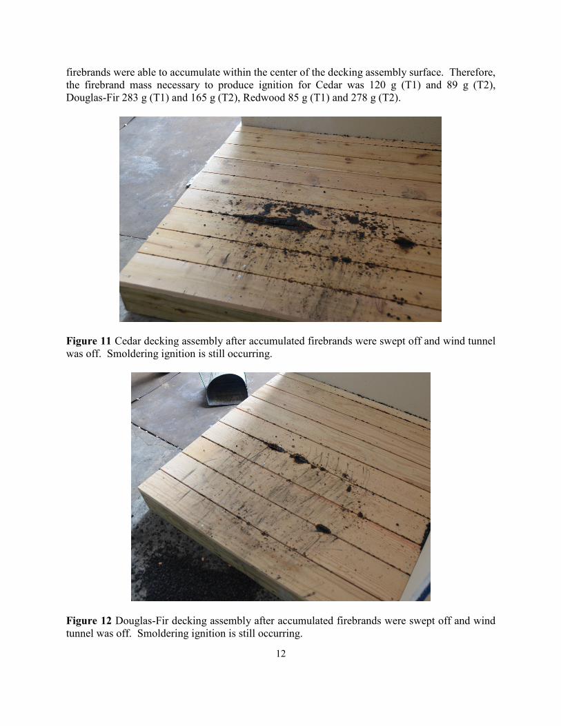
12
firebrands were able to accumulate within the center of the decking assembly surface. Therefore, the firebrand mass necessary to produce ignition for Cedar was 120 g (T1) and 89 g (T2), Douglas-Fir 283 g (T1) and 165 g (T2), Redwood 85 g (T1) and 278 g (T2).
Figure 11 Cedar decking assembly after accumulated firebrands were swept off and wind tunnel was off. Smoldering ignition is still occurring.
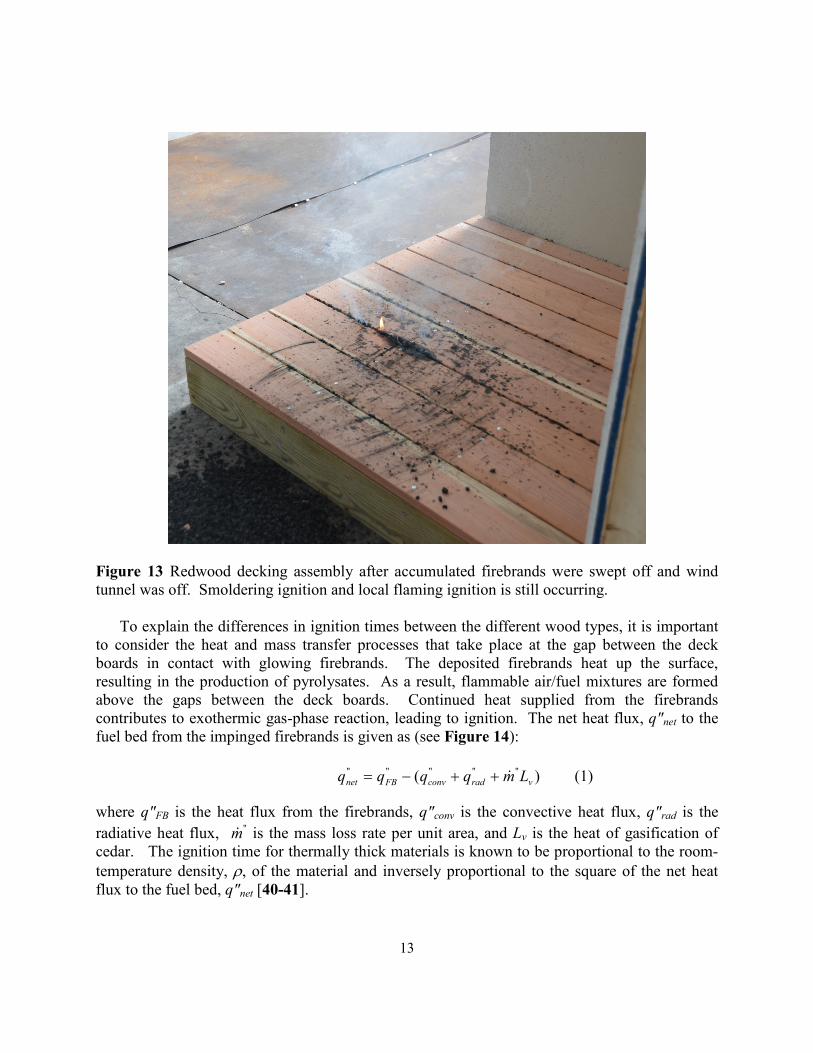
Figure 12 Douglas-Fir decking assembly after accumulated firebrands were swept off and wind tunnel was off. Smoldering ignition is still occurring.
13
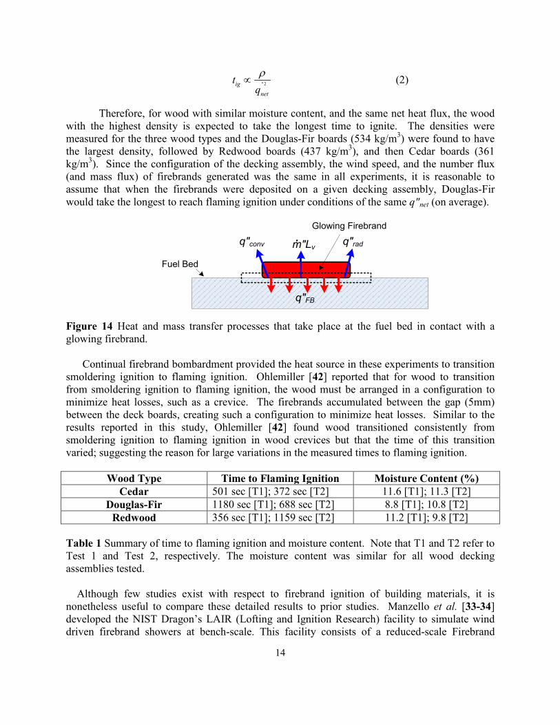
Figure 13 Redwood decking assembly after accumulated firebrands were swept off and wind tunnel was off. Smoldering ignition and local flaming ignition is still occurring.
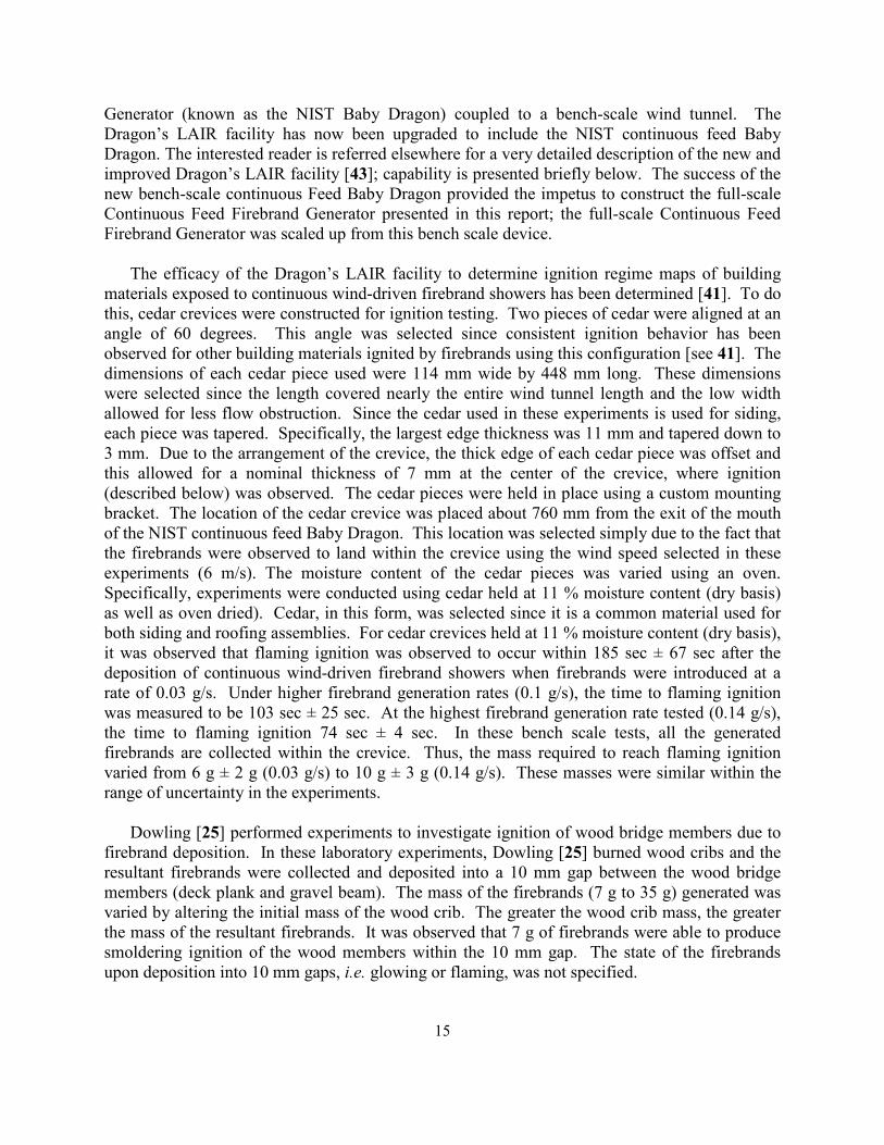
To explain the differences in ignition times between the different wood types, it is important to consider the heat and mass transfer processes that take place at the gap between the deck boards in contact with glowing firebrands. The deposited firebrands heat up the surface, resulting in the production of pyrolysates. As a result, flammable air/fuel mixtures are formed above the gaps between the deck boards. Continued heat supplied from the firebrands contributes to exothermic gas-phase reaction, leading to ignition. The net heat flux, q"net to the fuel bed from the impinged firebrands is given as (see Figure 14):
)( """""
vradconvFBnet Lmqqqq ++−= (1)
where q"FB is the heat flux from the firebrands, q"conv is the convective heat flux, q"rad is the radiative heat flux, "m is the mass loss rate per unit area, and Lv is the heat of gasification of cedar. The ignition time for thermally thick materials is known to be proportional to the room- temperature density, ρ, of the material and inversely proportional to the square of the net heat flux to the fuel bed, q"net [40-41].
14
"2ignet
tqρ
∝ (2)
Therefore, for wood with similar moisture content, and the same net heat flux, the wood with the highest density is expected to take the longest time to ignite. The densities were measured for the three wood types and the Douglas-Fir boards (534 kg/m3) were found to have the largest density, followed by Redwood boards (437 kg/m3), and then Cedar boards (361 kg/m3). Since the configuration of the decking assembly, the wind speed, and the number flux (and mass flux) of firebrands generated was the same in all experiments, it is reasonable to assume that when the firebrands were deposited on a given decking assembly, Douglas-Fir would take the longest to reach flaming ignition under conditions of the same q"net (on average).
q"FB
q"radq"conv.m"Lv
Fuel Bed
Glowing Firebrand
Figure 14 Heat and mass transfer processes that take place at the fuel bed in contact with a glowing firebrand.
Continual firebrand bombardment provided the heat source in these experiments to transition smoldering ignition to flaming ignition. Ohlemiller [42] reported that for wood to transition from smoldering ignition to flaming ignition, the wood must be arranged in a configuration to minimize heat losses, such as a crevice. The firebrands accumulated between the gap (5mm) between the deck boards, creating such a configuration to minimize heat losses. Similar to the results reported in this study, Ohlemiller [42] found wood transitioned consistently from smoldering ignition to flaming ignition in wood crevices but that the time of this transition varied; suggesting the reason for large variations in the measured times to flaming ignition.
Wood Type Time to Flaming Ignition Moisture Content (%)
Cedar 501 sec [T1]; 372 sec [T2] 11.6 [T1]; 11.3 [T2] Douglas-Fir 1180 sec [T1]; 688 sec [T2] 8.8 [T1]; 10.8 [T2]
Redwood 356 sec [T1]; 1159 sec [T2] 11.2 [T1]; 9.8 [T2] Table 1 Summary of time to flaming ignition and moisture content. Note that T1 and T2 refer to Test 1 and Test 2, respectively. The moisture content was similar for all wood decking assemblies tested.
Although few studies exist with respect to firebrand ignition of building materials, it is
nonetheless useful to compare these detailed results to prior studies. Manzello et al. [33-34] developed the NIST Dragon’s LAIR (Lofting and Ignition Research) facility to simulate wind driven firebrand showers at bench-scale. This facility consists of a reduced-scale Firebrand
15
Generator (known as the NIST Baby Dragon) coupled to a bench-scale wind tunnel. The Dragon’s LAIR facility has now been upgraded to include the NIST continuous feed Baby Dragon. The interested reader is referred elsewhere for a very detailed description of the new and improved Dragon’s LAIR facility [43]; capability is presented briefly below. The success of the new bench-scale continuous Feed Baby Dragon provided the impetus to construct the full-scale Continuous Feed Firebrand Generator presented in this report; the full-scale Continuous Feed Firebrand Generator was scaled up from this bench scale device.
The efficacy of the Dragon’s LAIR facility to determine ignition regime maps of building
materials exposed to continuous wind-driven firebrand showers has been determined [41]. To do this, cedar crevices were constructed for ignition testing. Two pieces of cedar were aligned at an angle of 60 degrees. This angle was selected since consistent ignition behavior has been observed for other building materials ignited by firebrands using this configuration [see 41]. The dimensions of each cedar piece used were 114 mm wide by 448 mm long. These dimensions were selected since the length covered nearly the entire wind tunnel length and the low width allowed for less flow obstruction. Since the cedar used in these experiments is used for siding, each piece was tapered. Specifically, the largest edge thickness was 11 mm and tapered down to 3 mm. Due to the arrangement of the crevice, the thick edge of each cedar piece was offset and this allowed for a nominal thickness of 7 mm at the center of the crevice, where ignition (described below) was observed. The cedar pieces were held in place using a custom mounting bracket. The location of the cedar crevice was placed about 760 mm from the exit of the mouth of the NIST continuous feed Baby Dragon. This location was selected simply due to the fact that the firebrands were observed to land within the crevice using the wind speed selected in these experiments (6 m/s). The moisture content of the cedar pieces was varied using an oven. Specifically, experiments were conducted using cedar held at 11 % moisture content (dry basis) as well as oven dried). Cedar, in this form, was selected since it is a common material used for both siding and roofing assemblies. For cedar crevices held at 11 % moisture content (dry basis), it was observed that flaming ignition was observed to occur within 185 sec ± 67 sec after the deposition of continuous wind-driven firebrand showers when firebrands were introduced at a rate of 0.03 g/s. Under higher firebrand generation rates (0.1 g/s), the time to flaming ignition was measured to be 103 sec ± 25 sec. At the highest firebrand generation rate tested (0.14 g/s), the time to flaming ignition 74 sec ± 4 sec. In these bench scale tests, all the generated firebrands are collected within the crevice. Thus, the mass required to reach flaming ignition varied from 6 g ± 2 g (0.03 g/s) to 10 g ± 3 g (0.14 g/s). These masses were similar within the range of uncertainty in the experiments.
Dowling [25] performed experiments to investigate ignition of wood bridge members due to
firebrand deposition. In these laboratory experiments, Dowling [25] burned wood cribs and the resultant firebrands were collected and deposited into a 10 mm gap between the wood bridge members (deck plank and gravel beam). The mass of the firebrands (7 g to 35 g) generated was varied by altering the initial mass of the wood crib. The greater the wood crib mass, the greater the mass of the resultant firebrands. It was observed that 7 g of firebrands were able to produce smoldering ignition of the wood members within the 10 mm gap. The state of the firebrands upon deposition into 10 mm gaps, i.e. glowing or flaming, was not specified.
16
When comparing the mass required for cedar crevice ignition of Manzello and Suzuki [41], to the deck results reported here, it was observed that the decking assemblies required significantly more mass of firebrands to produce flaming ignition. This was expected since the firebrands were not allowed to accumulate in such a tight, V-shaped crevice as the bench-scale experiments, resulting in larger heat losses (see Equation 1). Nevertheless, flaming ignition of decking assemblies was observed with total firebrand masses from 85 g to 280 g. This is not a significant amount of mass and could easily be generated during WUI fires.
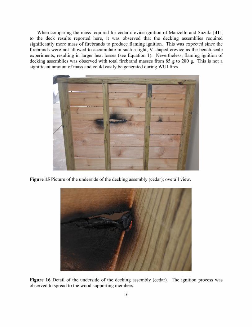
Figure 15 Picture of the underside of the decking assembly (cedar); overall view.
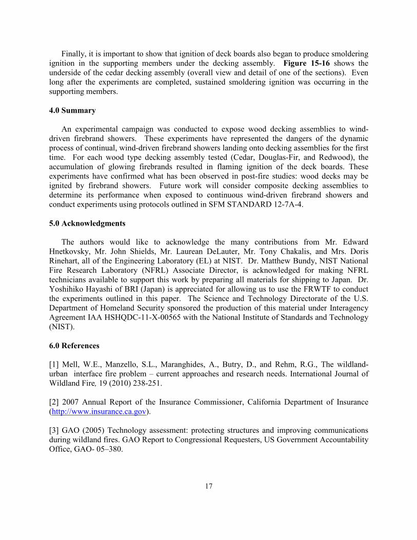
Figure 16 Detail of the underside of the decking assembly (cedar). The ignition process was observed to spread to the wood supporting members.
17
Finally, it is important to show that ignition of deck boards also began to produce smoldering ignition in the supporting members under the decking assembly. Figure 15-16 shows the underside of the cedar decking assembly (overall view and detail of one of the sections). Even long after the experiments are completed, sustained smoldering ignition was occurring in the supporting members. 4.0 Summary
An experimental campaign was conducted to expose wood decking assemblies to wind- driven firebrand showers. These experiments have represented the dangers of the dynamic process of continual, wind-driven firebrand showers landing onto decking assemblies for the first time. For each wood type decking assembly tested (Cedar, Douglas-Fir, and Redwood), the accumulation of glowing firebrands resulted in flaming ignition of the deck boards. These experiments have confirmed what has been observed in post-fire studies: wood decks may be ignited by firebrand showers. Future work will consider composite decking assemblies to determine its performance when exposed to continuous wind-driven firebrand showers and conduct experiments using protocols outlined in SFM STANDARD 12-7A-4. 5.0 Acknowledgments
The authors would like to acknowledge the many contributions from Mr. Edward Hnetkovsky, Mr. John Shields, Mr. Laurean DeLauter, Mr. Tony Chakalis, and Mrs. Doris Rinehart, all of the Engineering Laboratory (EL) at NIST. Dr. Matthew Bundy, NIST National Fire Research Laboratory (NFRL) Associate Director, is acknowledged for making NFRL technicians available to support this work by preparing all materials for shipping to Japan. Dr. Yoshihiko Hayashi of BRI (Japan) is appreciated for allowing us to use the FRWTF to conduct the experiments outlined in this paper. The Science and Technology Directorate of the U.S. Department of Homeland Security sponsored the production of this material under Interagency Agreement IAA HSHQDC-11-X-00565 with the National Institute of Standards and Technology (NIST). 6.0 References [1] Mell, W.E., Manzello, S.L., Maranghides, A., Butry, D., and Rehm, R.G., The wildland-urban interface fire problem – current approaches and research needs. International Journal of Wildland Fire, 19 (2010) 238-251. [2] 2007 Annual Report of the Insurance Commissioner, California Department of Insurance (http://www.insurance.ca.gov). [3] GAO (2005) Technology assessment: protecting structures and improving communications during wildland fires. GAO Report to Congressional Requesters, US Government Accountability Office, GAO- 05–380.
18
[4] HSPD (2004) Homeland Security Presidential Directive/HSPD-8 (http://www.fas.org/irp/offdocs/nspd/hspd-8.html). [5] Barrow, G.J. (1945). A survey of houses affected in the Beaumaris fire, January 14, 1944. Journal of the Council for Scientific and Industrial Research [now CSIRO] 18, 27-37. [6] Wilson A.A.G., Ferguson I.S., Predicting the Probability of House survival During Bushfires, Journal of Environmental Management, 23 (1986) 259-270. [7] Abt R., Kelly D., Kuypers M., The Florida Palm Coast Fire: An Analysis of Fire Incidence and Residence Characteristics, Fire Technology, 23 (1987) 186–197. [8] Gordon D.A., Structure Survival in the Urban/Wildland Interface: A Logistic Regression Analysis of the Oakland/Berkeley Tunnel Fire, MS thesis, University of California at Berkeley, 2000, 447 pp. [9] Maranghides, A., Mell, W.E., A Case Study of A Community Affected by the Witch and Guejito Fires, Fire Technology, 47 (2011) 379-420. [10] Albini, F., Spot Fire Distances From Burning Trees – A Predictive Model, USDA Forest Service General Technical Report INT-56, Missoula, MT, 1979. [11] Albini, F., Transport of Firebrands by Line Thermals, Combustion Science and Technology 32 (1983) 277-288. [12] Muraszew, A., Fedele, J.F., Statistical Model for Spot Fire Spread, The Aerospace Corporation Report No. ATR-77758801, Los Angeles, CA, 1976. [13] Tarifa, C.S., del Notario, P.P., Moreno, F.G., On the Flight Paths and Lifetimes of Burning Particles of Wood, Proceedings of the Combustion Institute 10 (1965) 1021- 1037. [14] Tarifa, C.S., del Notario, P.P., Moreno, F.G., Transport and Combustion of Fire Brands.’ Instituto Nacional de Tecnica Aerospacial “Esteban Terradas”, Final Report of Grants FG-SP 114 and FG-SP-146, Vol. 2. (Madrid, Spain) 1967. [15] Tse, S.D., Fernandez-Pello, A.C., On the Flight Paths of Metal Particles and Embers Generated by Power Lines in High Winds and their Potential to Initiate Wildfires, Fire Safety Journal 30 (1998) 333-356. [16] Anthenian, R., Tse, S.D., Fernandez-Pello, A.C., On the Trajectories of Embers Initially Elevated or Lofted by Small Scale Ground Fire Plumes in High Winds, Fire Safety Journal 41 (2006) pp. 349-363. [17] Woycheese, J.P., Brand Lofting and Propagation for Large-Scale Fires, Ph.D. Thesis, University of California, Berkeley, 2000.
19
[18] Himoto, K., Tanaka, T., Transport of Disk-Shaped Firebrands in a Turbulent Boundary Layer, in: D. Gottuk and B. Lattimer (Eds.) Fire Safety Science- Proceedings of the Eighth International Symposium, IAFSS, (2005) pp. 433-444. [19] Knight, I.K., The Design and Construction of a Vertical Wind Tunnel for the Study of Untethered Firebrands in Flight, Fire Technology 37 (2001) pp. 87-100. [20] Wang, H.H., Analysis of Downwind Distribution of Firebrands Sourced from a Wildland fire, Fire Technology, 47 (2011) pp. 321-340. [21] Waterman, T.E., Experimental Study of Firebrand Generation, IIT Research Institute, Project J6130, Chicago, IL, 1969. [22] Suzuki, S., Manzello, S.L., Lage, M., and Laing, G., Firebrand Generation Data Obtained From a Full Scale Structure Burn, International Journal of Wildland Fire (2012) in press. [23] Manzello, S. L., et al., Mass and Size Distribution of Firebrands Generated from Burning Korean Pine (Pinus koraiensis) Trees, Fire and Materials 33 (2009) pp. 21–31. [24] Waterman, T.E., Takata, A.E., Laboratory Study of Ignition of Host Materials by Firebrands, Project J-6142-OCD Work Unit 2539A, IIT Research Institute, Chicago, IL 1969. [25] Dowling, V.P., Ignition of Timber Bridges in Bushfires, Fire Safety Journal 22 (1994) pp. 145-168. [26] Ellis, P.F., The Aerodynamic and Combustion Characteristics of Eucalypt Bank - A Firebrand Study, PhD Dissertation, Australian National University, Canberra, 2000. [27] Ganteaume, A., Lampin-Maillet, C., Guijarro, M., Hernando, C., Jappiot, M., Fonturbel, T., Perez-Gorostiaga, P., Vega, J.A., Spot Fires: Fuel Bed Flammability and Capability of Firebrands to Ignite Fuel Beds, International Journal of Wildland Fire 18 (8) (2009) pp. 951–969. [28] Manzello, S.L., Cleary, T.G., Shields, J.R., Yang, J.C., Ignition of Mulch and Grasses by Firebrands in Wildland–Urban Interface (WUI) Fires, International Journal of Wildland Fire 15 (2006) pp. 427-431. [29] Manzello, S.L., Foote, E.I.D., Characterizing Firebrand Exposure During Wildland-Urban Interface Fires: Results of the 2007 Angora Fire, Fire Technology, in press (2012). DOI: 10.1007/s10694-012-0295-4. [30] Manzello, S.L., Shields, J.R., Yang, J.C., Hayashi, Y., Nii, D., On the Use of a Firebrand Generator to Investigate the Ignition of Structures in WUI Fires, In Proceedings of the 11th International Conference on Fire Science and Engineering (INTERLFAM), Interscience Communications, London, (2007) pp. 861-872.
20
[31] Manzello, S.L., Shields, J.R., Hayashi, Y., Nii, D., Investigating the Vulnerabilities of Structures to Ignition From a Firebrand Attack, in: B. Karlsson (Ed.) Fire Safety Science- Proceedings of the Ninth International Symposium,vol.9, IAFSS, (2008) pp.143–154. [32] Manzello, S.L., Hayashi, Y., Yoneki, Y., Yamamoto, Y., Quantifying the Vulnerabilities of Ceramic Tile Roofing Assemblies to Ignition During a Firebrand Attack, Fire Safety Journal 45 (2010) pp. 35-43. [33] Manzello, S.L., Park, S.H., Shields, J.R., Hayashi, Y., Suzuki, S., Comparison Testing Protocol for Firebrand Penetration Through Building Vents: Summary of BRI/NIST Full Scale and NIST Reduced Scale Results, NIST TN 1659, January, 2010. [34] Manzello, S.L., Park, S.H., Shields, J.R., Suzuki, S., Hayashi., Y., Determining Structure Vulnerabilities to Firebrand Showers in Wildland-Urban Interface (WUI) Fires, Fire Safety Journal 46 (2011) 568-578. [35] Manzello, S.L., Suzuki, S., and Hayashi, Y., Exposing Siding Treatments, Walls Fitted with Eaves, and Glazing Assemblies to Firebrand Showers. Fire Safety Journal 50 (2012), 25-34. [36] http://www.disastersafety.org [37] California Building Standards Commission Website (http://www.bsc.ca.gov/default.htm).
[38] ASTM E108 “Fire Standards and Flammability Standards” ASTM International, West Conshohocken, PA, (2003) doi: 10.1520/E0108-10A, www.astm.org. [39] Manzello SL, Suzuki, S (2011) Summary of 2011 Workshop on Research Needs for Full Scale Testing to Determine Vulnerabilities of Decking Assemblies to Ignition by Firebrand Showers. NIST Special Publication 1129. [40] Tewarson, A. (2nd Ed.) Generation of Heat and Chemical Compounds in Fires, SFPE Handbook of Fire Protection Engineering, NFPA, 1992, p.3-53. [41] Manzello, S.L., and Suzuki, S., The New and Improved Dragon’s LAIR (Lofting and Ignition Research) Facility, Fire and Materials, published online, doi: 10.1002/fam.1123. [42] Ohlemiller T., Smoldering Combustion Propagation on Solid Wood in: G. Cox (Ed.) Fire Safety Science-Proceedings of the Third International Symposium, Elsevier, Vol. 3 IAFSS, p. 565 (1991).