Embed Size (px)
Citation preview

1
CE591 Fall 2013
Lecture 26: Moment Connections
Explain basic design procedure for moment (FR)
connections
Explain considerations for connections in moment-
resisting frames for seismic demands
Describe problems observed with the “pre-
Northridge” connection and detailing
Describe some of the requirements for the “WUF-B”
connection developed after Northridge
Describe some other connections, including current
AISC prequalified connections

2
Welded Moment Connections
Develop moment
(typically Mpbeam )
at joint
Prefer compact
sections
Specify Complete
Joint Penetration
Weld (CJP) with
“matching” weld CJP Weld
Shear Tab
Beam
Column
3
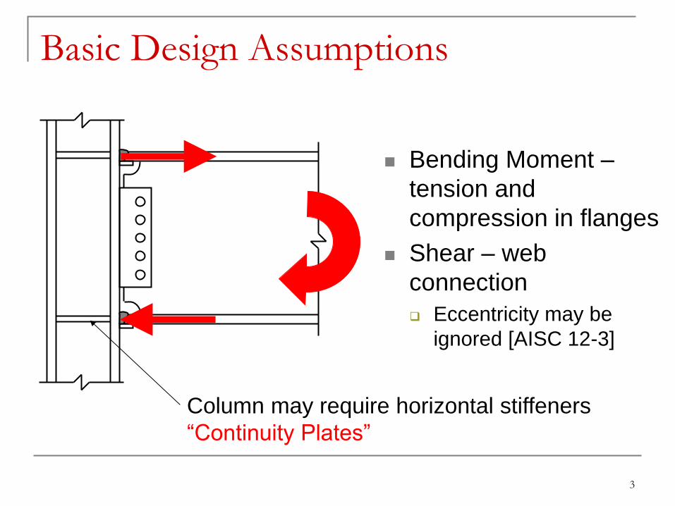
Basic Design Assumptions
Bending Moment –
tension and
compression in flanges
Shear – web
connection
Eccentricity may be
ignored [AISC 12-3]
Column may require horizontal stiffeners
“Continuity Plates”
4
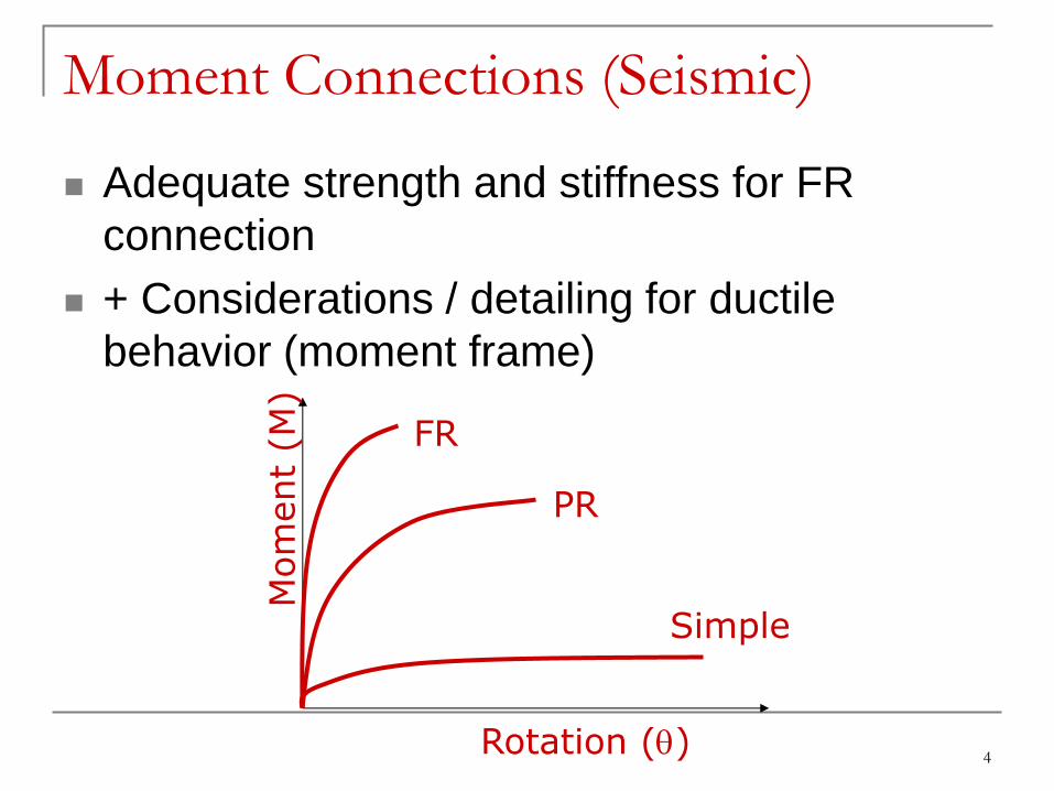
Moment Connections (Seismic)
Adequate strength and stiffness for FR
connection
+ Considerations / detailing for ductile
behavior (moment frame)
Rotation (q)
Mom
ent
(M)
FR
PR
Simple
5
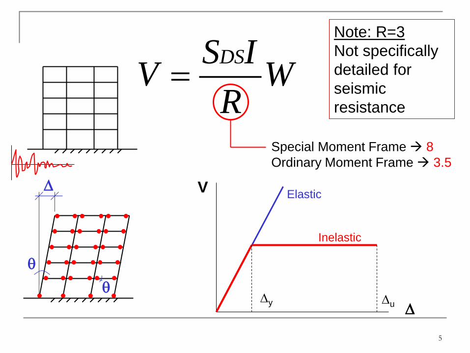
DSS IV W
R
Special Moment Frame 8
Ordinary Moment Frame 3.5
V
D
Elastic
Inelastic
Dy Du
D
q
q
Note: R=3
Not specifically
detailed for
seismic
resistance
6
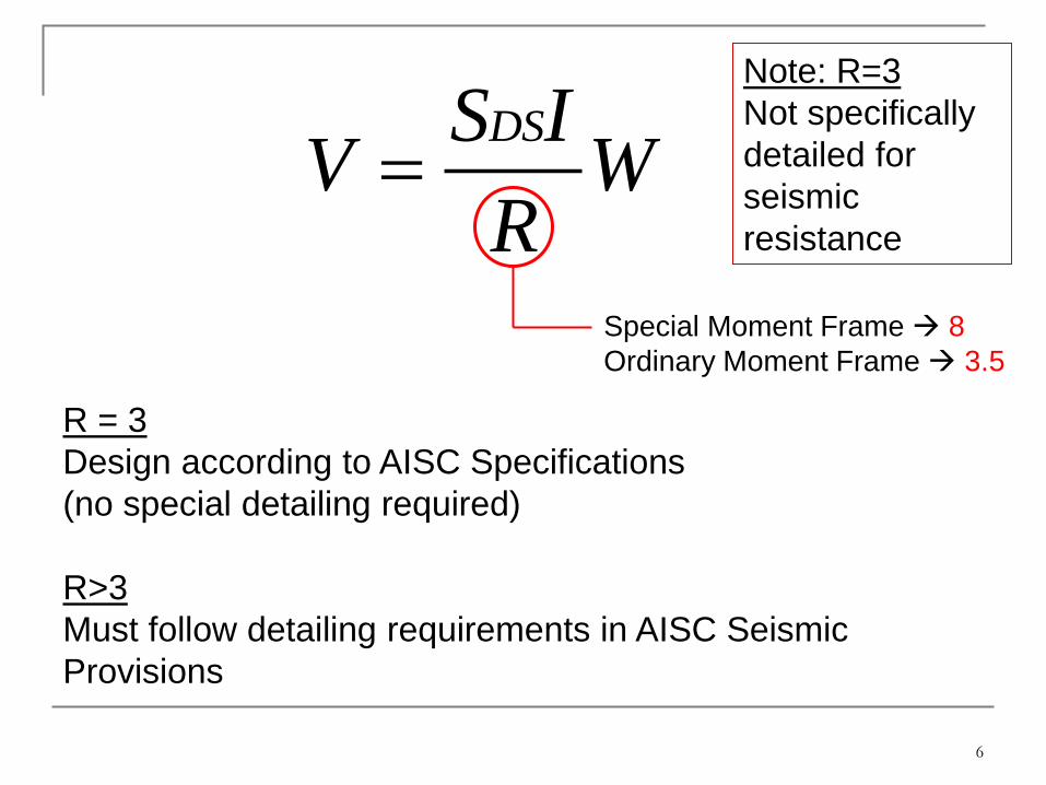
Special Moment Frame 8
Ordinary Moment Frame 3.5
Note: R=3
Not specifically
detailed for
seismic
resistance
R = 3
Design according to AISC Specifications
(no special detailing required)
R>3
Must follow detailing requirements in AISC Seismic
Provisions
DSS IV W
R

7
Strong Column – Weak Beam Concept
0.1*
*
pb
pc
M
M Mpb
Mpc
Includes reduction for axial force in column
Includes factors to
increase based on
expected yield
stress, etc.
AISC Seismic Provisions 2010, Section E3

8
Expected Strength Factor, Ry
Hot-rolled
Shapes
Ry
A36 1.5
A992 1.1 nominaly
expectedy
F
F
AISC Seismic Provisions 2010, Table A3.1

9
10
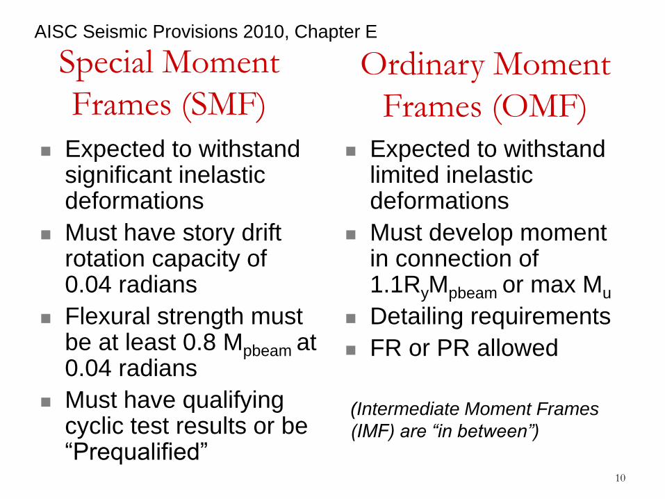
Special Moment
Frames (SMF)
Expected to withstand significant inelastic deformations
Must have story drift rotation capacity of 0.04 radians
Flexural strength must be at least 0.8 Mpbeam at 0.04 radians
Must have qualifying cyclic test results or be “Prequalified”
Expected to withstand limited inelastic deformations
Must develop moment in connection of 1.1RyMpbeam or max Mu
Detailing requirements
FR or PR allowed
Ordinary Moment
Frames (OMF)
(Intermediate Moment Frames
(IMF) are “in between”)
AISC Seismic Provisions 2010, Chapter E
11
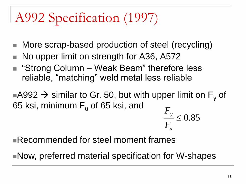
A992 Specification (1997)
More scrap-based production of steel (recycling)
No upper limit on strength for A36, A572
“Strong Column – Weak Beam” therefore less reliable, “matching” weld metal less reliable
85.0u
y
F
F
A992 similar to Gr. 50, but with upper limit on Fy of
65 ksi, minimum Fu of 65 ksi, and
Recommended for steel moment frames
Now, preferred material specification for W-shapes
12
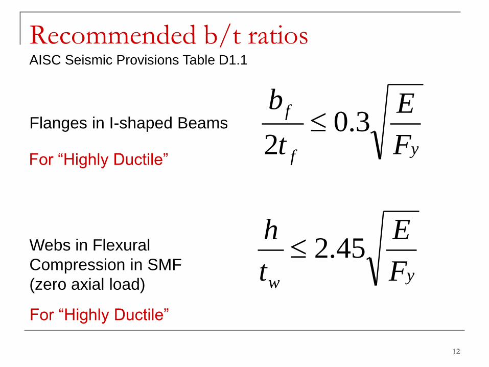
Recommended b/t ratios
yf
f
F
E
t
b3.0
2
yw F
E
t
h45.2
Flanges in I-shaped Beams
Webs in Flexural
Compression in SMF
(zero axial load)
AISC Seismic Provisions Table D1.1
For “Highly Ductile”
For “Highly Ductile”
13
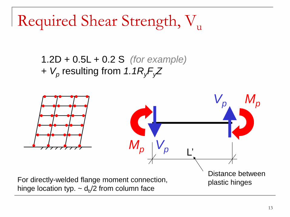
Required Shear Strength, Vu
1.2D + 0.5L + 0.2 S (for example)
+ Vp resulting from 1.1RyFyZ
Mp Vp
Mp Vp L’
Distance between
plastic hinges For directly-welded flange moment connection,
hinge location typ. ~ db/2 from column face
14
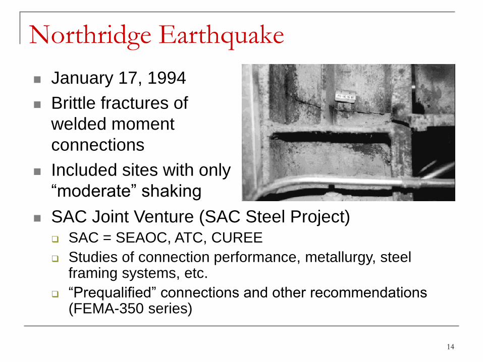
Northridge Earthquake
January 17, 1994
Brittle fractures of
welded moment
connections
Included sites with only
“moderate” shaking
SAC Joint Venture (SAC Steel Project) SAC = SEAOC, ATC, CUREE
Studies of connection performance, metallurgy, steel framing systems, etc.
“Prequalified” connections and other recommendations (FEMA-350 series)

15
Pre-Northridge Connection
Backing Bar
Weld Access Hole
CJP Weld
Shear Tab
Beam
Column
Continuity Plate
Panel Zone
16
Pre-Northridge Detail to “Prequalified”
WUF-B
WUF-B Welded Unreinforced Flange, Bolted Web
Detailing requirements, specified originally by FEMA-350
More stringent inspection requirements
Initially prequalified for Ordinary Moment Frames only; now, some WUF-B details are required for welded OMF (AISC Seismic Provisions 2010)

17
Welds Pre-Northridge
Low notch toughness
WUF-B
Specified notch toughness
e.g. 20 ft-lbs @ 0°F
Downhand field weld
results in defects,
“crack initiators”
18
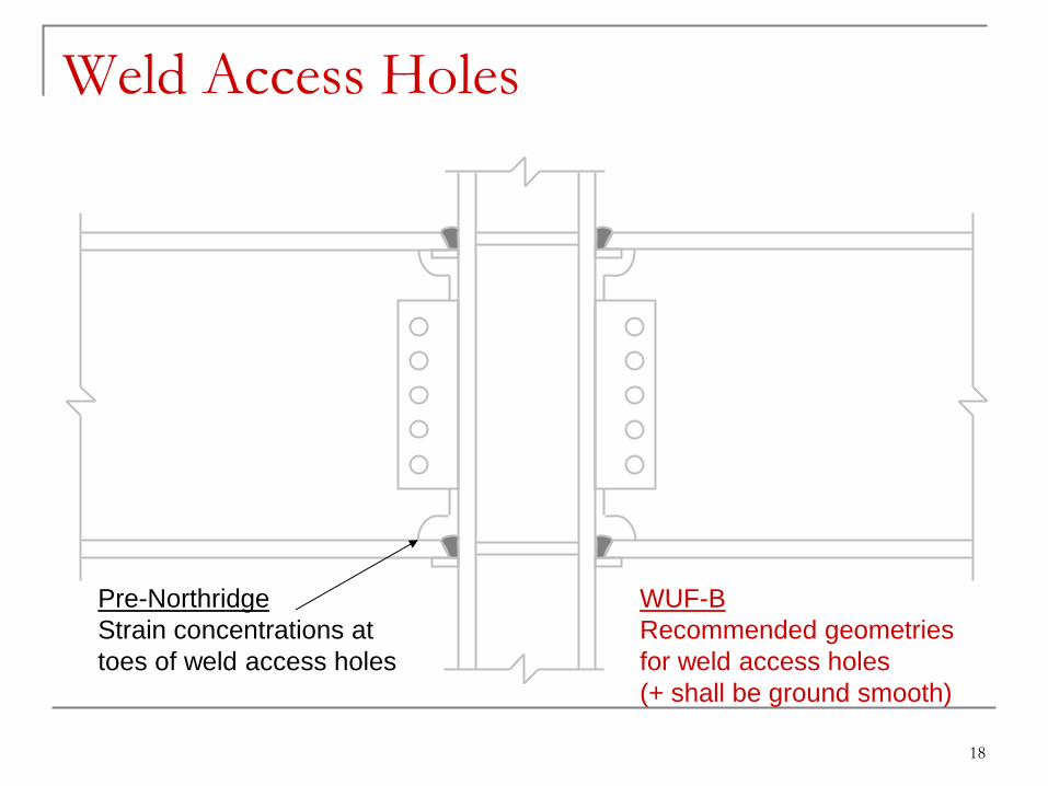
Weld Access Holes
Pre-Northridge
Strain concentrations at
toes of weld access holes
WUF-B
Recommended geometries
for weld access holes
(+ shall be ground smooth)

Improved Weld Access Hole
Notes:
1. Bevel as required for selected
groove weld.
2. Larger of tbf or ½ in. (13 mm) (plus ½
tbf, or minus ¼ tbf)
3. ¾ tbf to tbf, ¾ in. (19 mm) minimum (
¼ in.) ( 6 mm)
4. 3/8 in. (10 mm) minimum radius (plus
not limited, minus 0)
5. 3 tbf ( ½ in.) (13 mm)
Tolerances shall not accumulate to the
extent that the angle of the access
hole cut to the flange surface
exceeds 25.
Examples of requirements
20
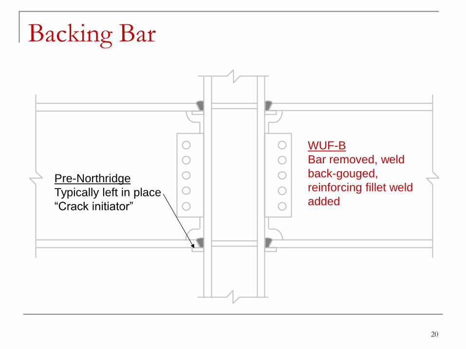
Backing Bar
Pre-Northridge
Typically left in place
“Crack initiator”
WUF-B
Bar removed, weld
back-gouged,
reinforcing fillet weld
added

21
Typical: 3/8” root
30-degree bevel on beam
flange
Bottom flange
back-up bar tack
welded into place.
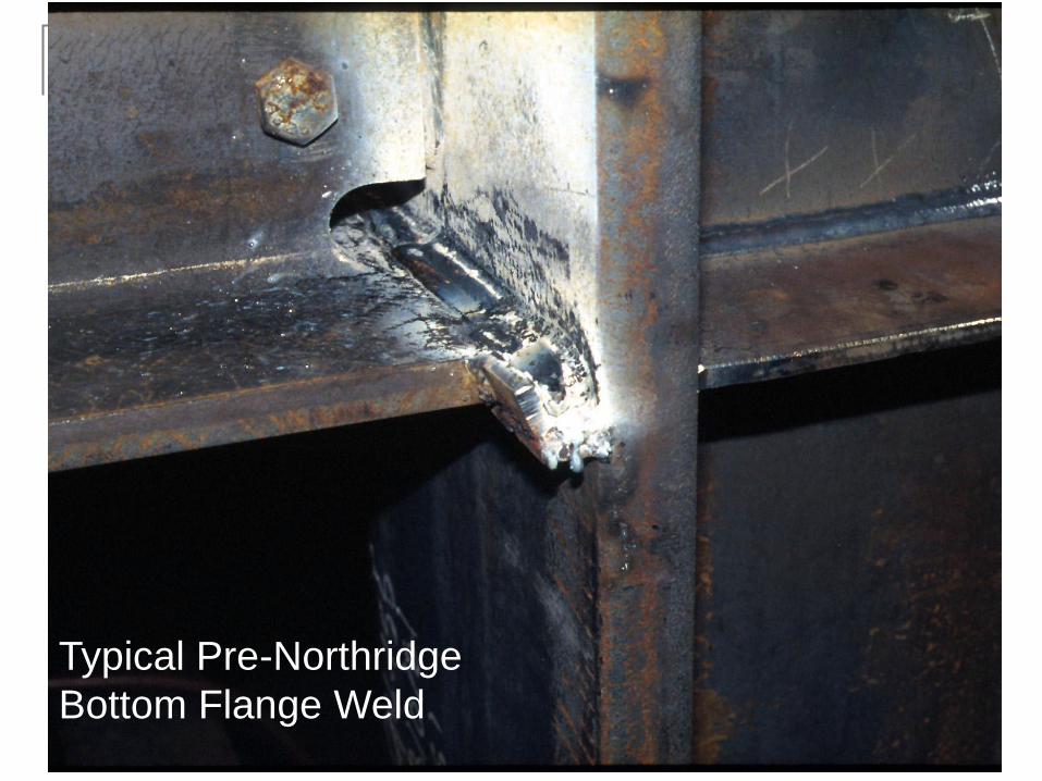
Typical Pre-Northridge
Bottom Flange Weld

Improved POST-Northridge Bottom Flange Weld
Weld tabs and
runoff regions
removed; ground
smooth
Back-up bar removed; root visually
inspected, defects removed; small
reinforcing fillet weld placed at
bottom of groove weld
24
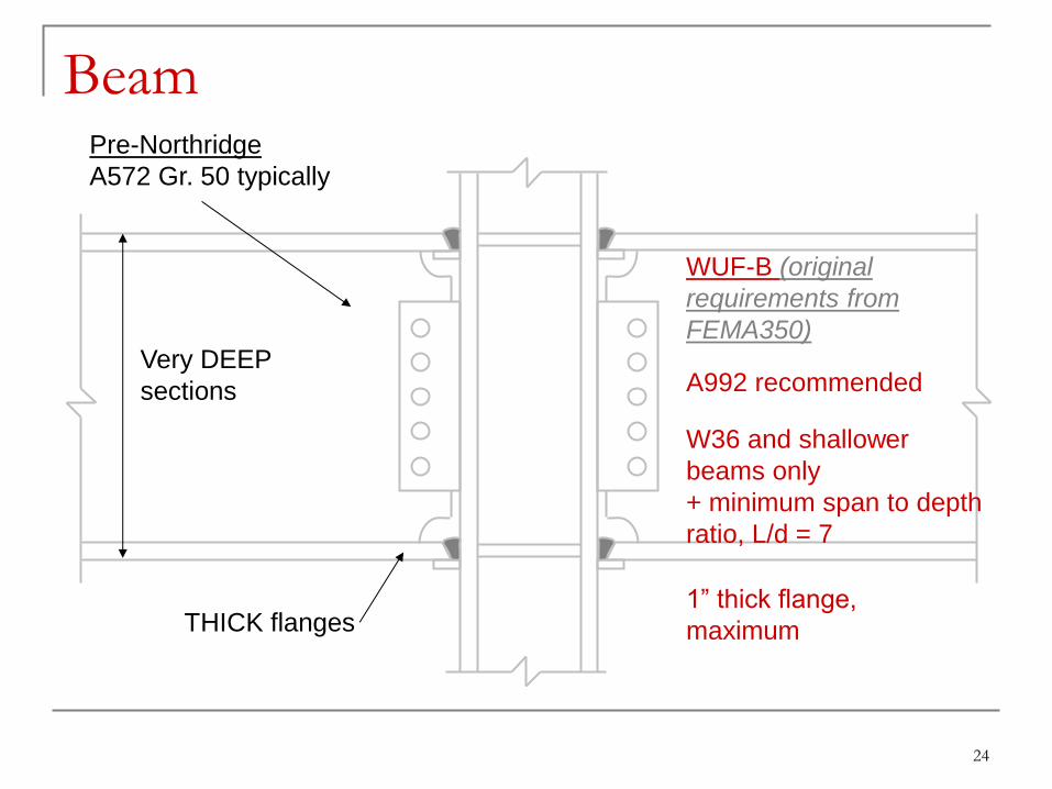
Beam Pre-Northridge
A572 Gr. 50 typically
WUF-B (original
requirements from
FEMA350)
A992 recommended Very DEEP
sections
W36 and shallower
beams only
+ minimum span to depth
ratio, L/d = 7
THICK flanges 1” thick flange,
maximum
25
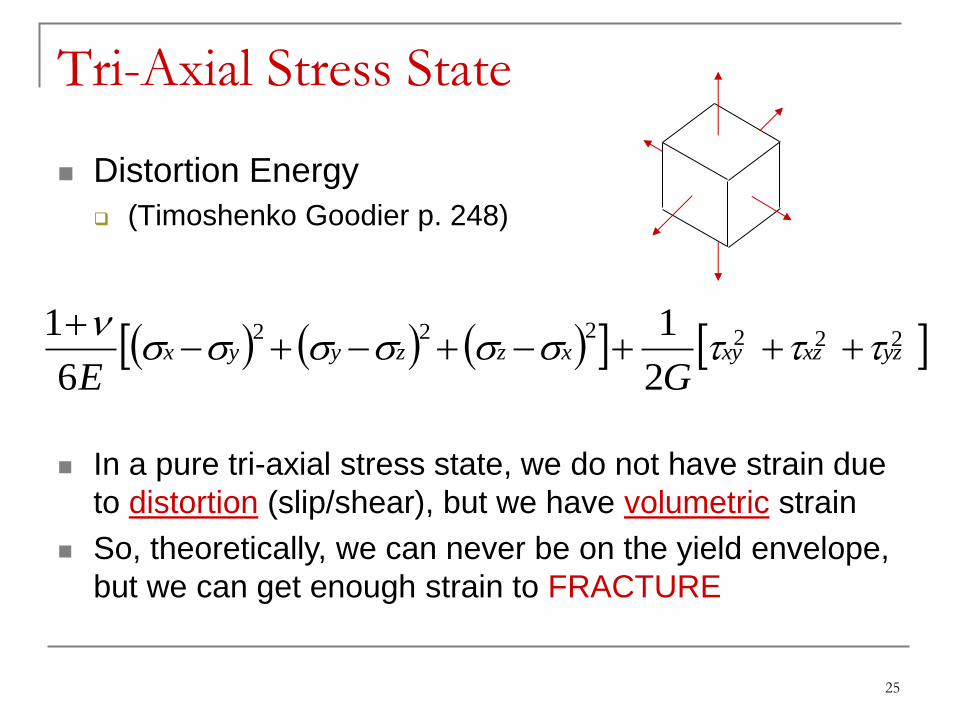
Tri-Axial Stress State
Distortion Energy
(Timoshenko Goodier p. 248)
In a pure tri-axial stress state, we do not have strain due
to distortion (slip/shear), but we have volumetric strain
So, theoretically, we can never be on the yield envelope,
but we can get enough strain to FRACTURE
222222
2
1
6
1yzxzxyxzzyyx
GE
26
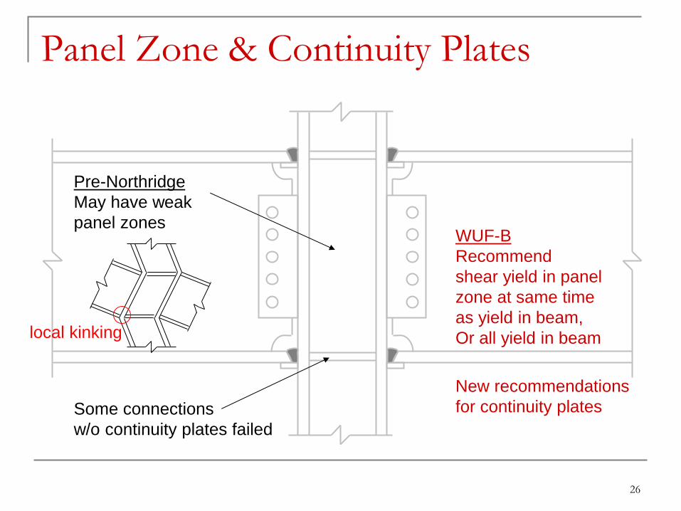
Panel Zone & Continuity Plates
Pre-Northridge
May have weak
panel zones WUF-B
Recommend
shear yield in panel
zone at same time
as yield in beam,
Or all yield in beam
Some connections
w/o continuity plates failed
New recommendations
for continuity plates
local kinking
27
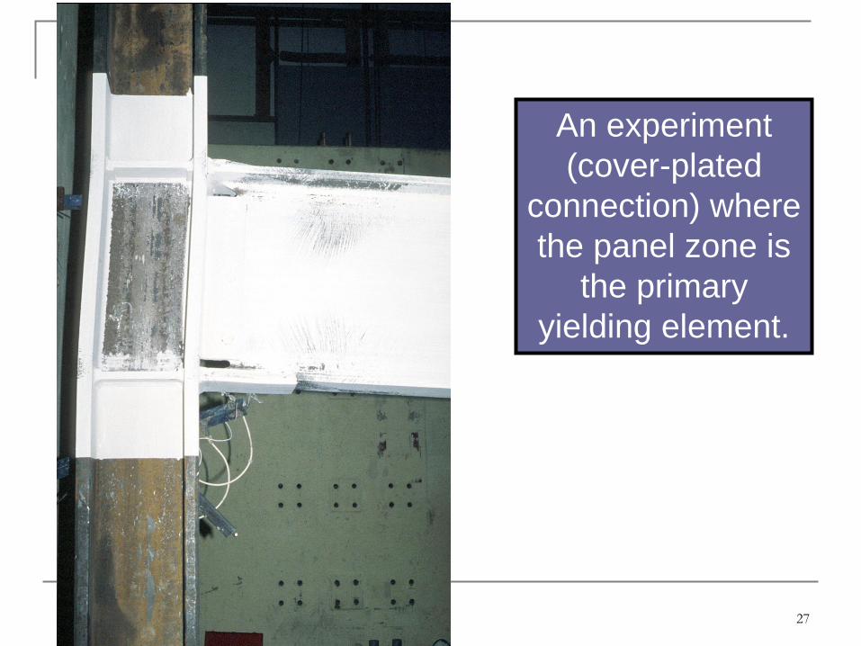
An experiment
(cover-plated
connection) where
the panel zone is
the primary
yielding element.
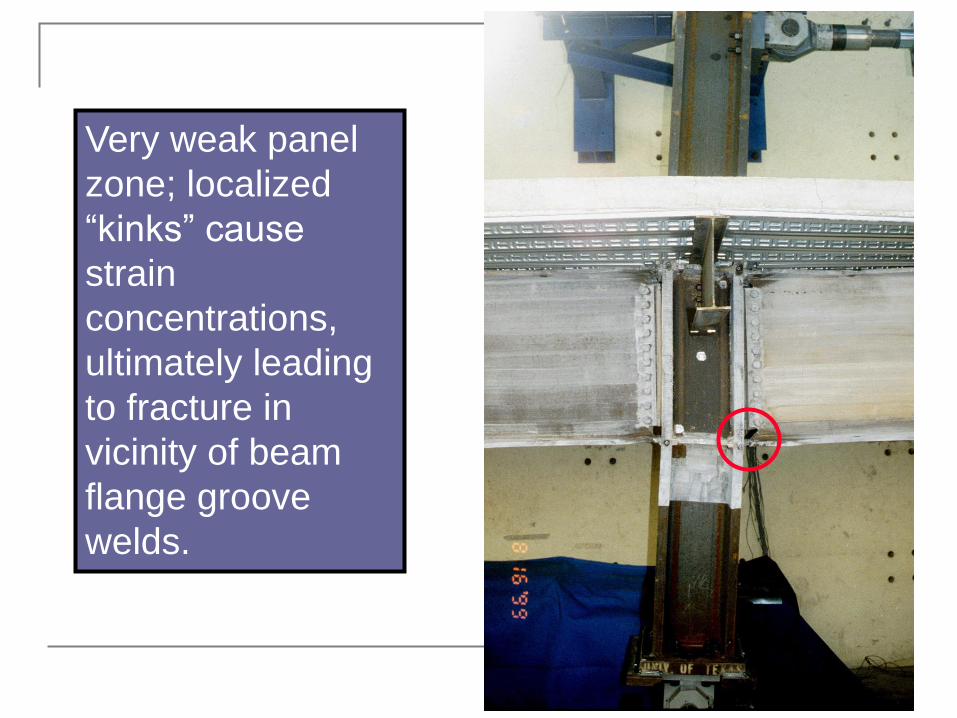
Very weak panel
zone; localized
“kinks” cause
strain
concentrations,
ultimately leading
to fracture in
vicinity of beam
flange groove
welds.

Same specimen
as previous slide.
Connection failed
at moment well
below Mn

FEMA 350
Moment connection
details -- “prequalified
connections”
Recommended design
procedures, limits of
usage (e.g., OMF only,
W36 beams and
shallower, flange
thickness limits, web
connection, etc.)
Not a standard; but
still a valuable
reference
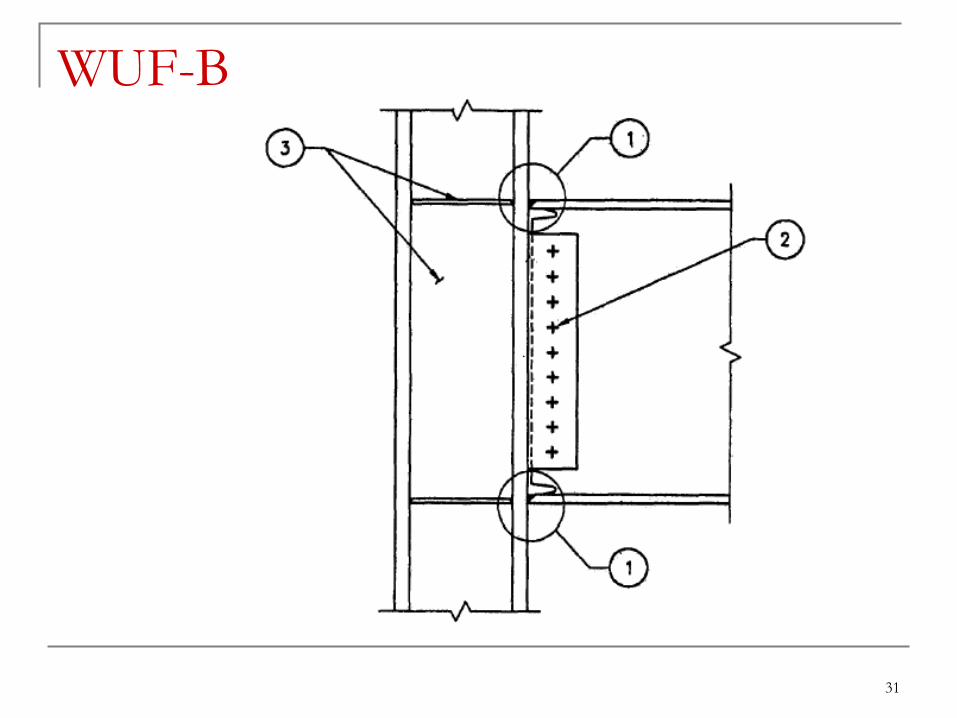
31
WUF-B
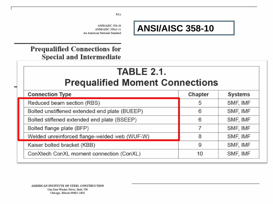
ANSI/AISC 358-10
33
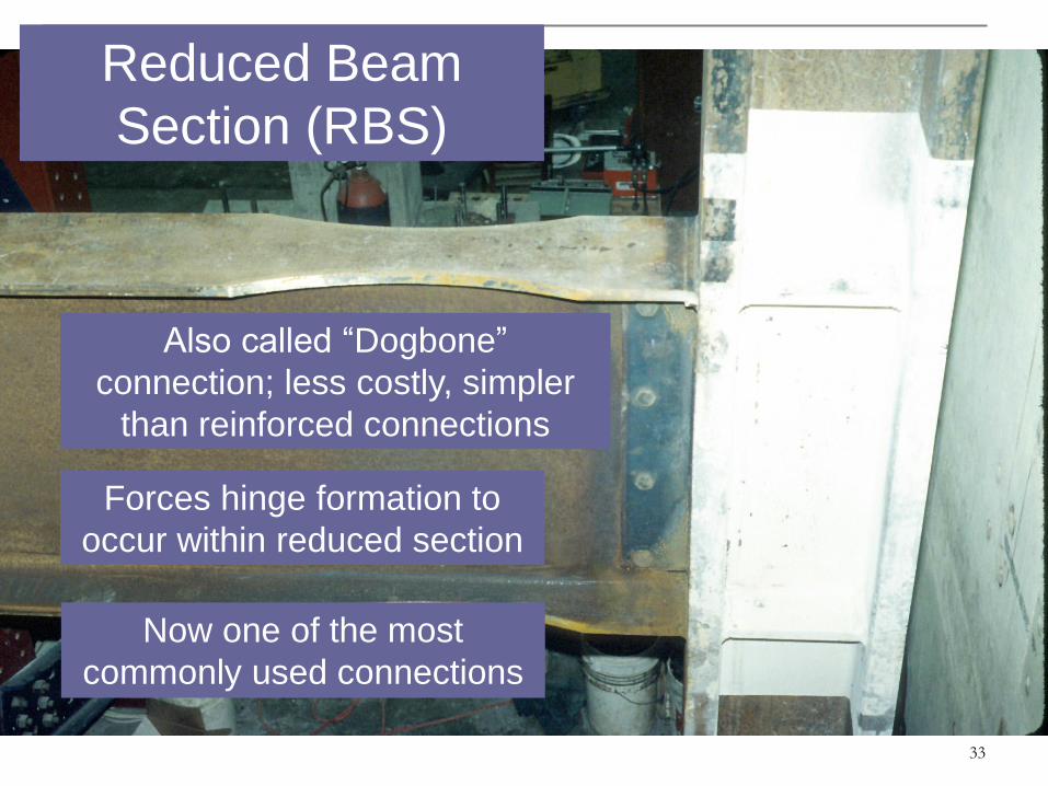
Reduced Beam
Section (RBS)
Also called “Dogbone”
connection; less costly, simpler
than reinforced connections
Forces hinge formation to
occur within reduced section
Now one of the most
commonly used connections
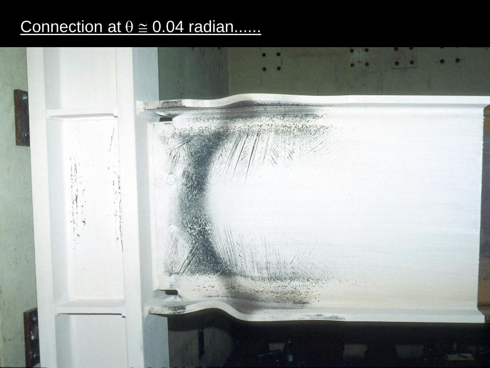
Connection at q 0.04 radian......

-5000
-4000
-3000
-2000
-1000
0
1000
2000
3000
4000
5000
-0.05 -0.04 -0.03 -0.02 -0.01 0 0.01 0.02 0.03 0.04 0.05
Drift Angle (radian)
Be
nd
ing
Mo
me
nt
(kN
-m)
RBS Connection
Mp
Mp
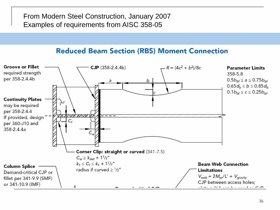
36
From Modern Steel Construction, January 2007
Examples of requirements from AISC 358-05

37
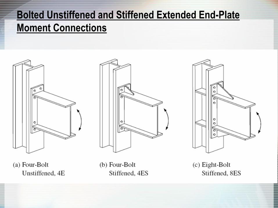
Bolted Unstiffened and Stiffened Extended End-Plate
Moment Connections

Sumner, et al., 2000
End-Plate Connections
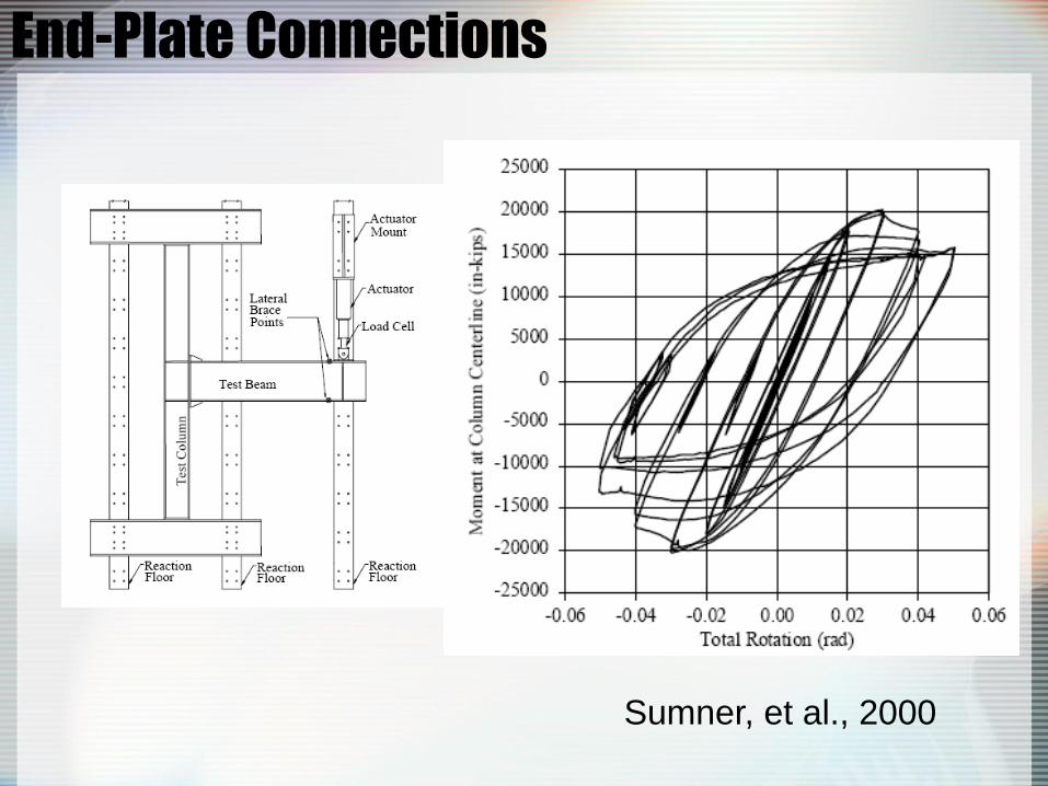
Sumner, et al., 2000
End-Plate Connections
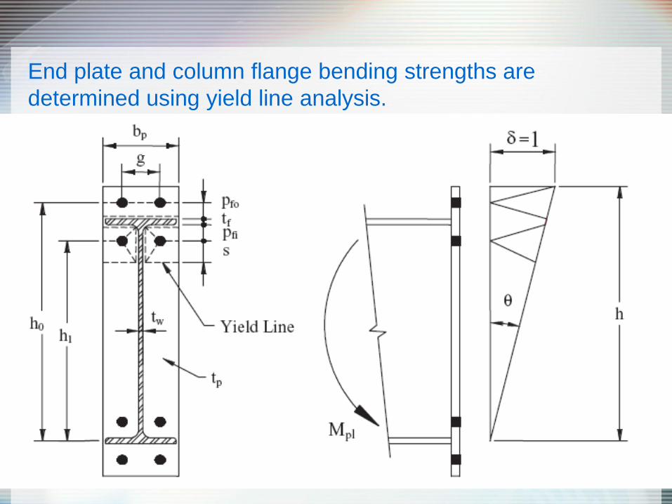
End plate and column flange bending strengths are
determined using yield line analysis.

Bolted Flange Plate (BFP)

BFP-3
Sato, A., Newell, J.D., Uang, C.-M.
“Cyclic Behavior and Seismic Design of
Bolted Flange Plate Steel Moment
Connections,” AISC Engineering
Journal, Fourth Quarter, 2008.
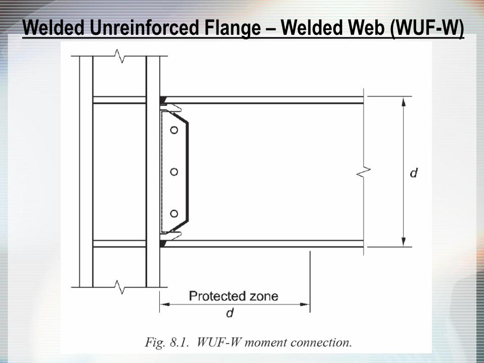
Welded Unreinforced Flange – Welded Web (WUF-W)

Section 8.6
Beam Web-to-
Column
Connection
Limitations
Shear tab thickness
equal at least to that
of beam web;
overlap with weld
access holes as
specified

Kaiser Bolted Bracket (KBB)
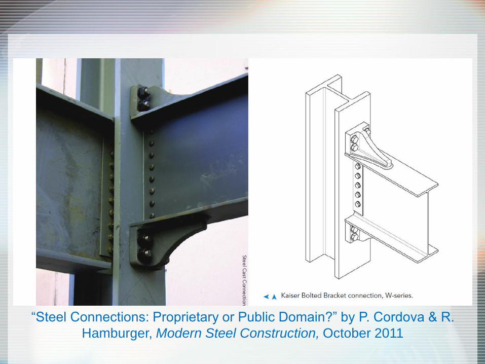
“Steel Connections: Proprietary or Public Domain?” by P. Cordova & R.
Hamburger, Modern Steel Construction, October 2011
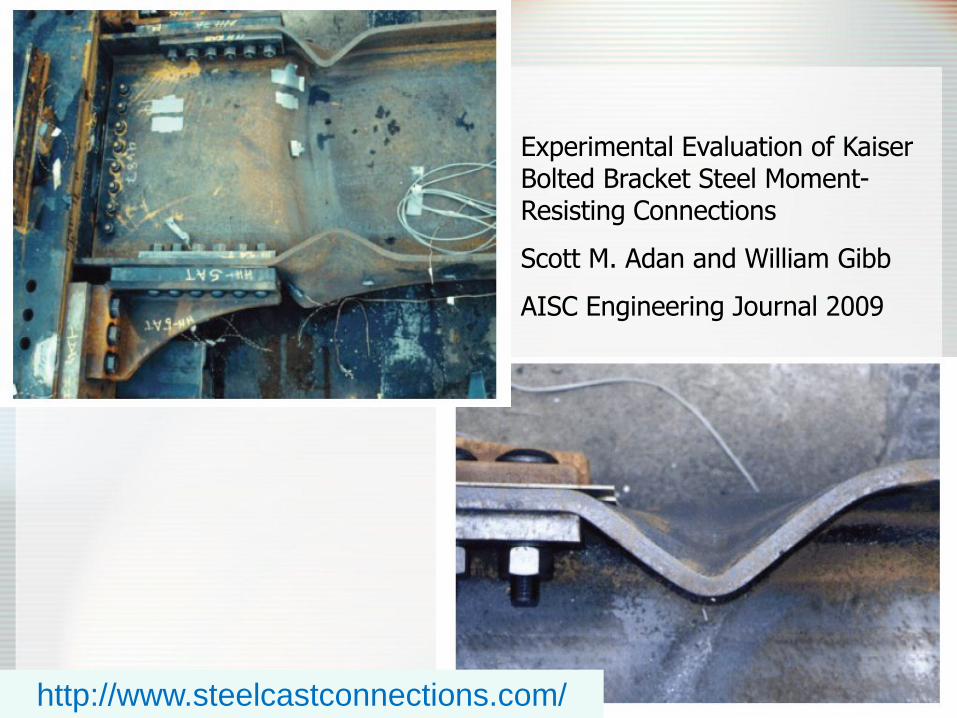
Experimental Evaluation of Kaiser Bolted Bracket Steel Moment-Resisting Connections
Scott M. Adan and William Gibb
AISC Engineering Journal 2009
http://www.steelcastconnections.com/
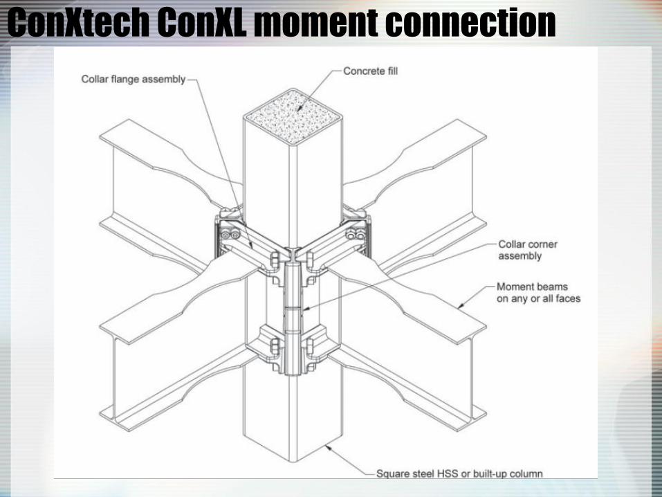
ConXtech ConXL moment connection
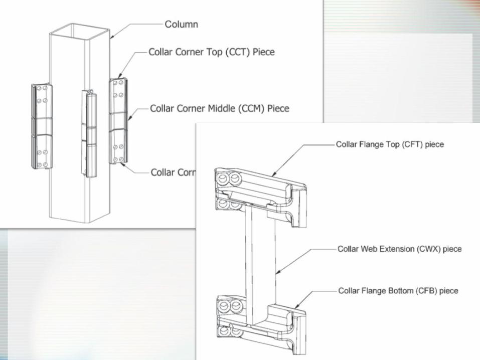

http://dcm-designs.com/steel-prefabricated-moment-frame/
“This innovative
connection system
enables beams to be
simply lowered and locked
onto square columns in
the field, resulting in a
dimensionally accurate
structural chassis. The
system is often referred to
as a full-scale erector set.”
http://www.conxtech.com
/conx-system/
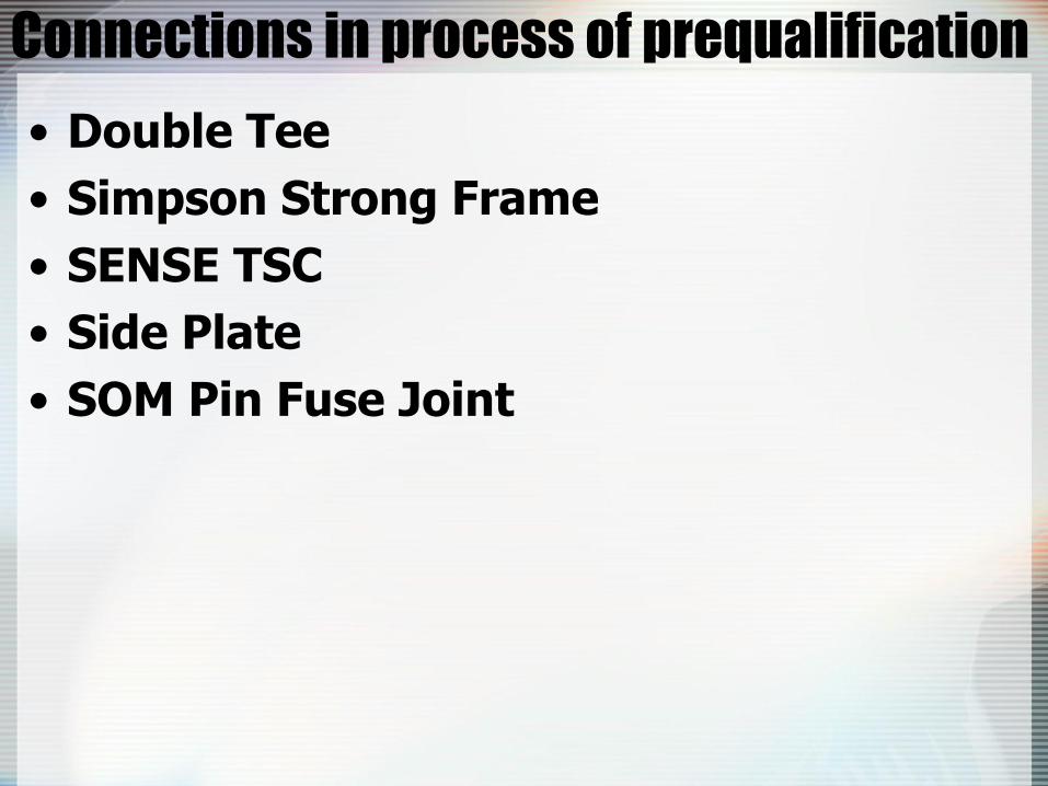
Connections in process of prequalification
• Double Tee
• Simpson Strong Frame
• SENSE TSC
• Side Plate
• SOM Pin Fuse Joint

Double Tee
http://www.aisc.org/uploadedcontent/2012NASCCSessions/N11/
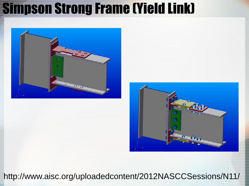
Simpson Strong Frame (Yield Link)
http://www.aisc.org/uploadedcontent/2012NASCCSessions/N11/

SENSE TSC
http://www.aisc.org/uploadedcontent/2012NASCCSessions/N11/
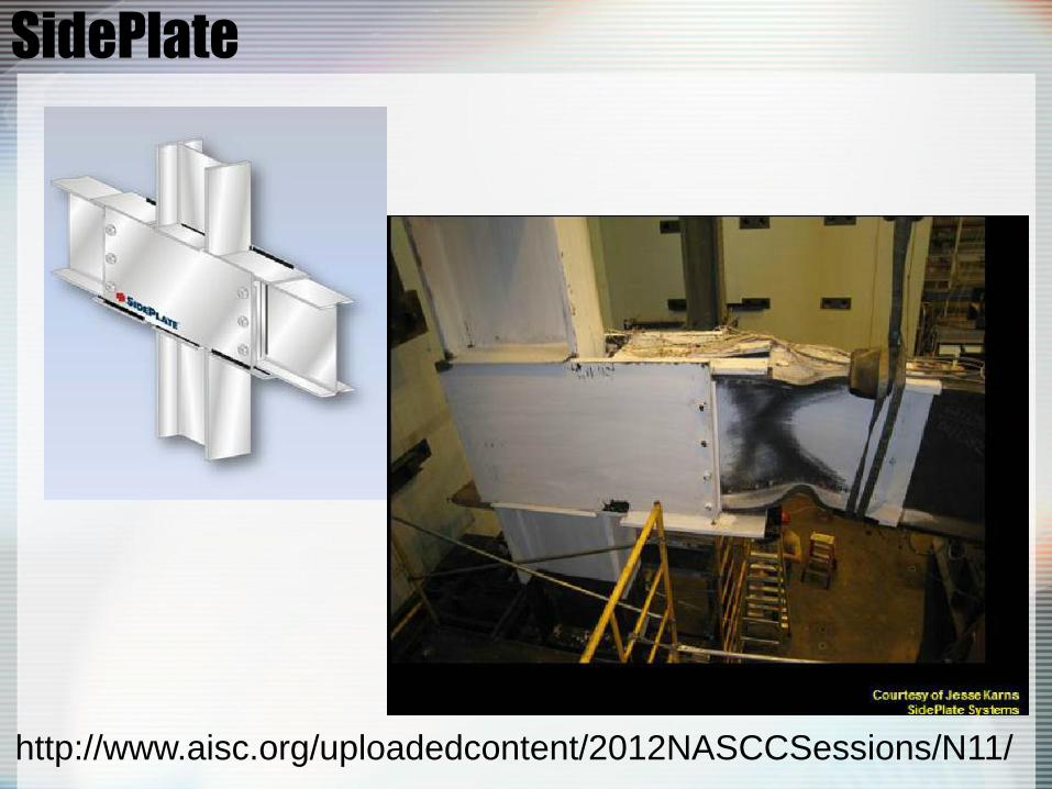
SidePlate
http://www.aisc.org/uploadedcontent/2012NASCCSessions/N11/

SOM Pin Fuse Joint
“Steel Connections: Proprietary or Public Domain?” by P. Cordova & R.
Hamburger, Modern Steel Construction, October 2011

http://www.som.com/content.cfm/pin_fuse_joint