Embed Size (px)
Citation preview
SmartCombi™ Service
CE & UL Version
Service manualElectric and Gas Combi
2011
/12/
29 S
EV/K
A
Model Serial-No. / datefrom thru
Electric:ESC 615 07020594 ESC 620 07020594 ESC 115 07020594 ESC 120 07020594 ESC 215 07020594 ESC 220 07020594
Gas:GSC 615 07020594 GSC 620 07020594 GSC 115 07020594 GSC 120 07020594 GSC 215 07020594 GSC 220 07020594
From software 3.00
1
SmartCombi™ Service
Preposition
The documentation may address the ovens as 6.x, 10.x and 20.x. These represent the size of the units in regards as the number of rails.
Henny Penny is using the following model numbers615620115120215220
These are equivalent to the following6.1 (61) – 6156.2 (62) – 62010.1 (101) – 11510.2 (102) – 12020.1 (201) – 21520.2 (202) – 220
DynaSteam =AST (AdvanceSteamTechnology)AutoChef = SmartMenuCombiPilot = CombiDial
2

SmartCombi™ Service
ContentsPreposition............................................................................................................................................2Functional diagram of the DynaSteam technology..............................................................................5The automatic cleaning system WaveClean II.....................................................................................6How to open the Front Panel and the Side Walls.................................................................................8Parts location 6.x / 10.x (left side view)...............................................................................................9Parts location 6.x / 10.x Gas (left side view)......................................................................................10Parts location 20.x Electric (left side view)........................................................................................11Parts location 20.x Electric (front view).............................................................................................12DynaSteam unit documentation.........................................................................................................13Basics of the gas technology..............................................................................................................16Diagram of the heating process „regular operating“..........................................................................19Diagram of the heating process „no gas present“...............................................................................20Diagram of the heating process „gas present, no flame detection“....................................................21CO2 Gas value calibration..................................................................................................................22Gas orifices and fan speeds CSA........................................................................................................24Gas orifices and fan speeds CE..........................................................................................................25Internal gas supply check...................................................................................................................26Check-up of the connection pressure (operating pressure)................................................................27Rearrangement of the gas type ..........................................................................................................28Adjustment of the cabinet door..........................................................................................................29Overview and compatibility summary of temperature probes...........................................................30Description of the frequency controller..............................................................................................31The main menu (Password overview & diagnosis memory) .............................................................33Service menu of the electronic (Configuration menu).......................................................................34Settings area (basic settings)..............................................................................................................44Generally measurement mask for electric units.................................................................................48Generally measurement mask for gas units........................................................................................50How to activate and disable the demo mode .....................................................................................52Reset of the electronic........................................................................................................................52Connecting a performance optimization system (LOA) ...................................................................52Connection of external facilities to the potential-free contact ...........................................................52How to change the display language..................................................................................................53Layout of relay pcb A1 Electric & Gas CE-Version........................................................................54Layout of relay pcb Electric & Gas UL-Version...............................................................................56Layout of keyboard pcb A2 Electric ................................................................................................58Layout of keyboard pcb A2 Gas .......................................................................................................59Fuse protection schematic for CE units..............................................................................................60Fuse protection schematic for UL Electric-Units (208V)..................................................................61Fuse protection schematic for UL Gas-Units (120V).........................................................................62Reserve relay K 17 rewiring instructions...........................................................................................63240V UL unit Set Up..........................................................................................................................65
3

SmartCombi™ Service
4
SmartCombi™ Service
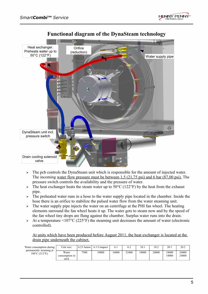
Functional diagram of the DynaSteam technology
➢ The pcb controls the DynaSteam unit which is responsible for the amount of injected water. The incoming water flow pressure must be between 1,5 (21,75 psi) and 6 bar (87,00 psi). The pressure switch controls the availability and the pressure of water.
➢ The heat exchanger heats the steam water up to 50°C (122°F) by the heat from the exhaust pipe.
➢ The preheated water runs in a hose to the water supply pipe located in the chamber. Inside the hose there is an orifice to stabilize the pulsed water flow from the water steaming unit.
➢ The water supply pipe injects the water on an centrifuge at the PHI fan wheel. The heating elements surround the fan wheel heats it up. The water gets to steam now and by the speed of the fan wheel tiny drops are flung against the chamber. Surplus water runs into the drain.
➢ At a temperature <107°C (225°F) the steaming unit decreases the amount of water (electronic controlled).
At units which have been produced before August 2011, the heat exchanger is located at the drain pipe underneath the cabinet.
Water consumption during permanently steaming at
100°C (212°F):
Unit size: 6.23 Junior 6.1 Compact 6.1 6.2 10.1 10.2 20.1 20.2
Water consumption in
ml/h
7500 10000 16000 21000 18000 24000 18000 18000
24000 24000
5
Heat exchanger.Preheats water up to
50°C (122°F)
Orifice(reduction)
DynaSteam unit incl. pressure switch
Drain cooling solenoid valve.
Water supply pipe

SmartCombi™ Service
The automatic cleaning system WaveClean II
Operational sequence of the cleaning systemThe automatic cleaning system WaveClean provides three different programs:• Short: Duration approx. one hour• Normal: Duration approx. two hours• Extra: Duration approx. three hours
Step Function01 - Depending on the cabinet temperature, the unit cools down to 55°C (131°F)02 - Siphon rinsing by solenoid valve Y12.
- Siphon cleaning by double water exchange. The drain pump M24 removes the water from the siphon. Afterwards the siphon gets filled by solenoid valve Y12.
03 - Cabinet pre-cleaning by active cycle pump M16 and fan motor. Afterwards one more siphon cleaning by water exchange.
04 - The cleaninig process- Fan motor and cycle pump M16 are active.- The heating element heats the unit up to 70°C (158°F).- The blue wax layer melts and the cleaning agent drops down.- The WaveClean pump circulates the cleaning water permanently.- To reach all positions, the fan runs in fast/slow and in right/left direction.- The duration of the cleaning sequence depends on the selected cleaning program.
6
Solenoid valve Y12
Pump M16
Pump M24

SmartCombi™ Service
Continuation description WaveClean II Step Function05 - The rinsing process
- Siphon (trap) cleaning by water exchange. - The drain pump removes the water from the siphon.
- The siphon gets filled with fresh water by the solenoid valve Y12 - One more water exchange to ensure that clean water is available for the rinsing cycle.
- Fan motor and WaveClean cycle pump M16 are active.. - The heating element heats the cabinet up to 92°C (198°F). - The sencond (yellow) wax layer melts and rinsing agents drops down. - The WaveClean pump circulates the rinsing water permanently. - To reach all positions the fan runs in fast/slow mode as well in right/left direction. - Final siphon water exchange by drain pump and solenoid valve. - When selected normal or extra program, the cabiinet gets dried by an additional dry-heat step.
06 - The unit switches off automatically after the cleaning program. - „Remove cartridge“ appears after switching the oven on again. This must be confirmed
by pushing the „confirm“ button.- The total water consumption is approx. 50 Liter – independent from the selected
cleaning program!- Approx. 3 Liter water running through the water steaming unit into the cabinet.
Note:
At an interruption of the power supply the cleaning process stopped automatically. A "cancellation program" which rinses the cabinet is started with a duration of 14 minutes.This program is carried out also at a manual cancellation.An entry is written down in the diagnosis and HACCP memory.
7

SmartCombi™ Service
How to open the Front Panel and the Side Walls
Dismounting of Side Walls:After dismounting of the two screws, the respective side wall can be removed.
Opening of the Front Panel: The Front Panel will be unlocked by turning the hexagon socket clockwise. Lift up the Front Panel careful and open it.
8
2 screws Hexagon screw 2 screws

SmartCombi™ Service
Parts location 6.x / 10.x (left side view)CE Version
9
Lift magnet Y8
Safty limit switch F7
Fan M1Heating element
Humidity probeB5
transformer T1
Solid state relaisV1/V2 heating system
Solid state relais V3(chamber lighting)
Cooling fan M7
Drain probe B4
WaveClean pump M16
Cold water assemblySolenoid valve Y12
DynaSteam unit
Not mapped: (position in front of the trap:WaveClean pump M24
Power connection andline filter

SmartCombi™ Service
Parts location 6.x / 10.x Gas (left side view)CE Version
10
Lift magnet Y8
Safety limit switch F7
fan M1
Humidity probeB5
DynaSteam unitCold water assemblysolenoid valve Y12
transformer T1
Drain probe B4
Cooling fan M7
WaveClean pump M16 (sidewisemounted)
Not mapped: (position in front of the trap)WaveClean pumo M24
Solid state relay V6(illumination)
Power connection andline filter
transformer T2(for glow electrode)
Ignition box N10
Gas blower U10
Gas valve
glow electrodeR10
Ionisation electrode

SmartCombi™ Service
Parts location 20.x Electric (left side view)CE Version
11
Lift magnet Y8
Safety limit switch F7
Fan motor M2Heating element E3
Humidity probe B5 (at upper fresh air pipe)
Transformer T1
Solid state relay V1/V2 heating (upper element)
Solid state relay V6(Illumination)
Cooling fan M7
Drain probe B4DynaSteam unit
Y10/Y11
WaveClean pump M24 (front)WaveClean pump M16 (aft)
Power connectionand filter
Cooling fan M7.1
DynaSteam unit Y20/Y21
Solenoid valve Y12
Solid state relay V3/V4 heating (lower element)
Safety limit switch F9
Heating element E2
Lift magnet Y8
Fan motor M1

SmartCombi™ Service
Parts location 20.x Electric (front view)CE Version
12
Fuses:F1: 10A slow blowF2: 10A slow blowF4: 6,3A slow blow
Frequency controller V10(for upper motor)
Main contactor K1
Frequency controller V20(for lower motor)
Buzzer H13
Contactor K3
Fuses F31 – F3335A
Fuses F21 – F2335A
Behind the protection cover:Control main pcb(Consisting of- Keyboard pcb A2- Relay pcb A1- Flash modul A2.2)
Reed contact switch S1(door contact)
CombiPilot S3
Rectifier V8
SmartCombi™ Service
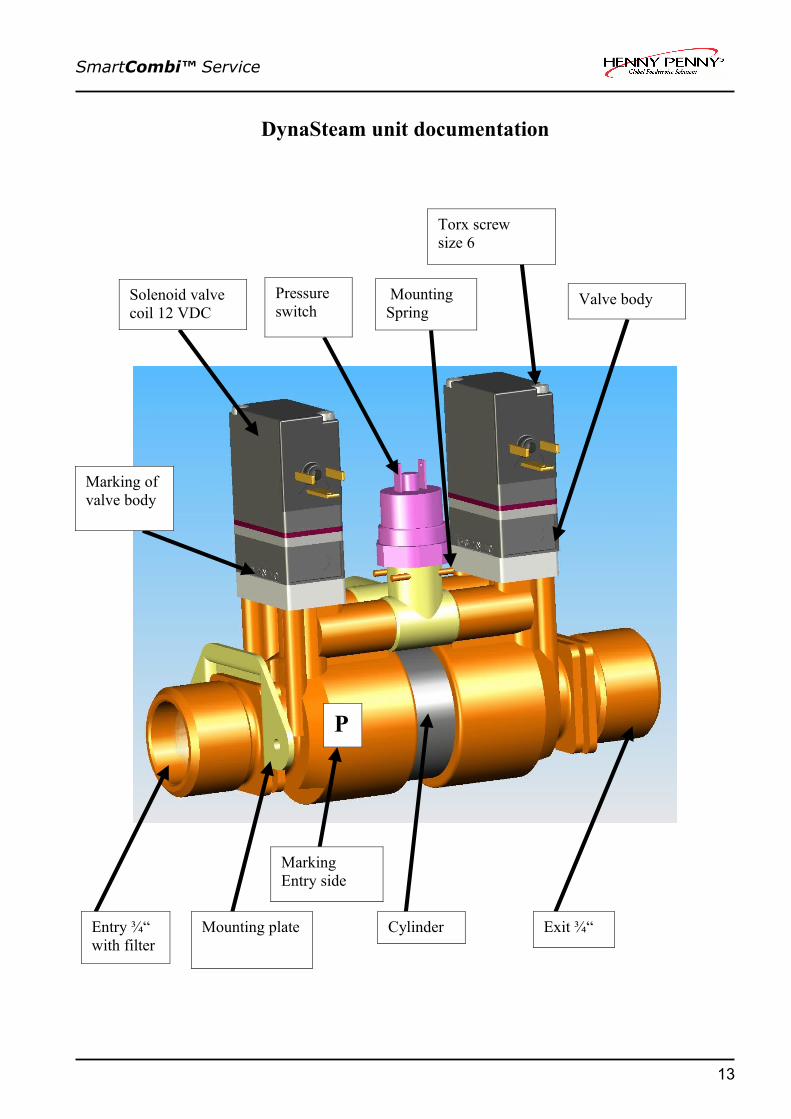
DynaSteam unit documentation
13
Solenoid valve coil 12 VDC 12V
Pressure switch
Mounting Spring
Torx screw size 6
Valve body
Entry ¾“ with filter
Mounting plate Exit ¾“
P
Marking Entry side
Cylinder
Marking of valve body

SmartCombi™ Service
Description
The unit is a volumetric proportion system for liquid substances. The unit produces a constant flow rate , independent from the incoming water pressure . The flowrate only depends on the frequency applied to the solenoids. The unit can have a water pressure switch to detect water pressure. The software of the machine determines the flow rate by adapting the frequency o the solenoids. A calibration is not needed nor possible. This technology has been engineered and patents applied by MKN.
Function
The unit consists of a cylinder with a double sided piston. The incoming water pressure drives the piston to one or the other side, depending which valve is active. The piston drives a specific volume of water to the outlet. Directly before the water enters the cooking chamber there is a orifice mounted inside the tube and held with a clamp. Do not operate the unit without that orifice. Due to the transparent cylinder the piston (seals) can be seen in motion.The solenoids are supplied with 12 V DC.The pressure switch is set for a pressure of 1 bar (14.5 psi). Operation of the unit is guaranteed up to 6 bar (87 psi)entry pressure. Higher entry pressure requires a pressure reducing valve in front of the unit.
Technical dataNormal Pressure Range: 1.5 – 6 bar (21.8 – 87 psi)burst pressure: >20 bar (>290 psi)Maximum flow rate: 28l/hVolume of cylinder: 7mlElectrical supply: 24V DC
Functioning Test
This setting starts a unit functioning test. In the menu “water calibration”, a defined volume flow of water is emitted. The authorised volume is shown in the main display, the actual flow must be determined by a measuring jug. To increase the water volume for better a measurement, this procedure may be repeated several times. The actual flow may deviate of the authorised flow by +/- 8% (e.g. for an authorised volume of 140ml, the minimum and maximum volumes are 129ml and 150ml respectively.The Summary information mask indicates the power supply of the unit by the signs B1 (energized) And B0 (not energized).Dual chamber units incorporate two units, which are parallel energized.Tip:During the cooking process, the volume flow cannot be determined because it frequently changes during the process.At delivery of the combisteamer the water system is empty. This may warrant more time until water reaches the cooking chamber. During this time, multiple calibration cycles may be initiated.
14
SmartCombi™ Service
Functional TroublesNotice:This unit allows the replacement of the pressure switch, the filter and the solenoid valves. Any further dismantling is not allowed (possible water damage, guarantee). After each replacement, a water proof test is obligatory.Replacement Of Solenoid ValvesShut off water supply. Release pressure in the entry lines. Unscrew the solenoid valves.Pay attention to the three O-rings mounted to the valve body. Take apart the valve body and clean the valve socket and openings. Carefully clean the valve membrane of sediments. Reassemble the valve unit (it fits only in easily the correct way). Check the correct location of the three O-rings. The valve unit must be assembled with the script heading towards the entry opening. Mount the valve body with a torque of 0.6 +/- 0.1Nm. Assemble the solenoid with the electric connector at the side of the decal P with a torque of 0.1 – 0.2Nm. Connect the electric supply to the solenoid valve. Mixing up the electrical valve connections is without consequences. Open the water supply and check the unit water proof.Fault Indication “No Water”Units with a pressure switch display the fault “No Water” in case the pressure switch is still open.Check entry water pressure. Check electrical connections. The pressure switch opens at 1bar.The switch point is adjusted by the inner hexagonal nut incorporated in the pressure switch.
Replacement Of Pressure Switch
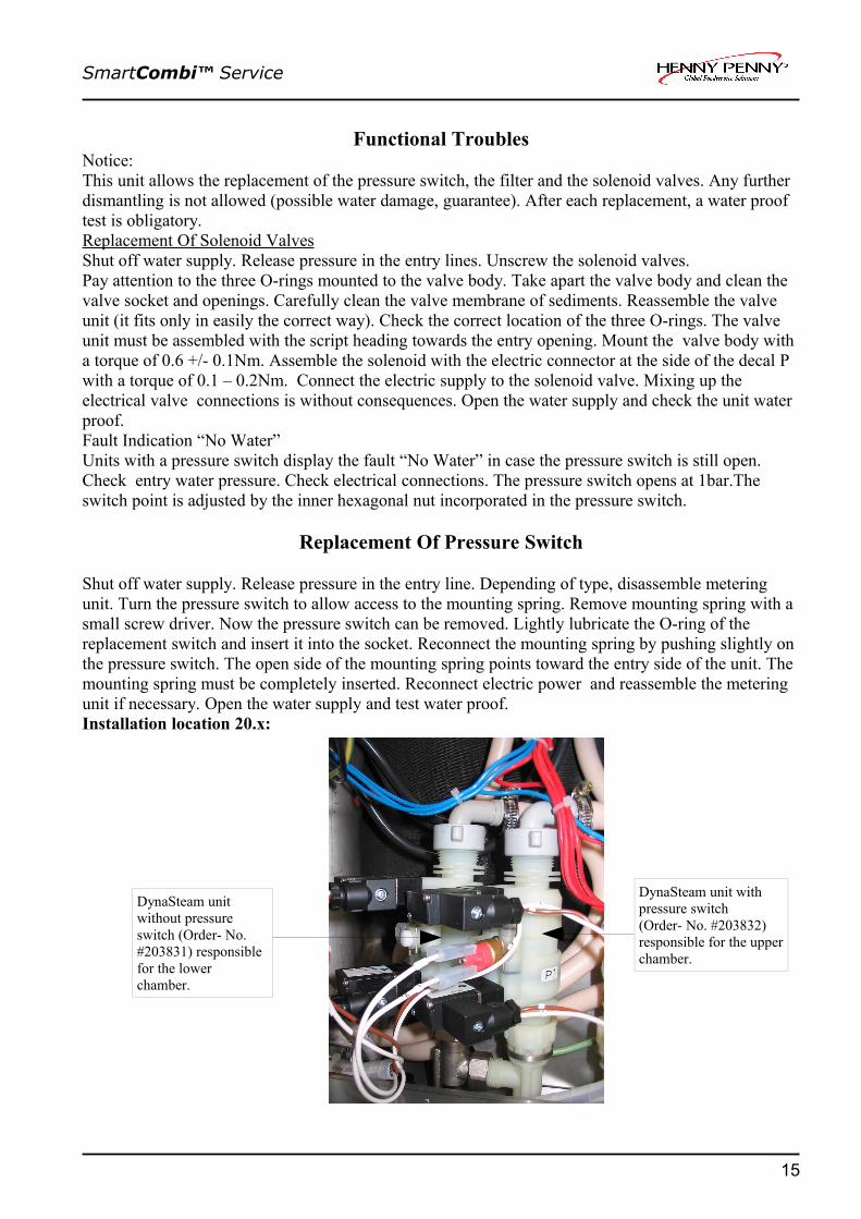
Shut off water supply. Release pressure in the entry line. Depending of type, disassemble metering unit. Turn the pressure switch to allow access to the mounting spring. Remove mounting spring with a small screw driver. Now the pressure switch can be removed. Lightly lubricate the O-ring of the replacement switch and insert it into the socket. Reconnect the mounting spring by pushing slightly on the pressure switch. The open side of the mounting spring points toward the entry side of the unit. The mounting spring must be completely inserted. Reconnect electric power and reassemble the metering unit if necessary. Open the water supply and test water proof.Installation location 20.x:
15
DynaSteam unit without pressure switch (Order- No. #203831) responsible for the lower chamber.
DynaSteam unit with pressure switch (Order- No. #203832) responsible for the upper chamber.

SmartCombi™ Service
Gas technologyBasics of the gas technology
Operation of the gas burner:
The electronic (pcb) gives a heat demand (relay K14 and K15) to the burner control. The electronic (pcb) regulates the speed of the gas fan and supervises these. The complete igniting process is handled by the burner control. At a failure of the flame signal from the burner control to the electronic the appliance is nevertheless ready for use. There is an electrical failure of the signal which safety-related is quite safe as long as no alarm is reported. (The burner control has recognized the flame (In this case there is "just"an error to transmit information to the electronic The burner control itself has already detected the flame).
Functional diagram
16
Elektronik A2Electronic board A2
X8.1 X8.3 (20.x)
X9.11 X9.8 (20.x)
Zündelektronik /Ignition box
Flammen Signal BGFlame Signal
Reset
Wärmeanforderung Heat demand
Relais board A1Relay board A1 X6.10 X6.11 (20.X)
X5.17 X5.15 (20.x)
X4.1 X4.3 (20.x)
OutIN
Alarm
Trafo/Transformer

SmartCombi™ Service
The gas fanThe gas fan promotes the air-/ gas mixture into the burner. The promoting volume and the performance are dependent on the speed of the gas fan. This is steered and supervised by the electronic. The speed only can be changed in a defined speed window which is dependent on the kind of gas and unit size. The speed window is basis of the equipment admittance and may not be changed. This regulation ensures that the gas fan speed works independently of outer influences (temperature and supply voltage). Fan speed control:The gas fan is / are controlled by a PWM signal (pulse width modulation) from the electronic A2, terminal X8.1 (6.x, 10.x, lower chamber at 20.x) and terminal X8.3 (upper chamber at unit size 20.x). Without PWM signal and with available supply voltage the gas fan runs for safety reasons with full speed. The gas fan transmit the fan speed to the electronic A2, terminal X9.11 (6.x, 10.x, 20.x lower chamber) and terminal X9.8 (only 20.x upper chamber) as a re-registration. The gas blower is regulated on set rotation speed by a software regulator. This can be check with the help of the configuration menu (service menu), step 9 "gas calibration". A speed fluctuation up to 50 rpm is normal.
17

SmartCombi™ Service
The ignition electrodeThe ignition electrode serves to ignite the gas/air mixture and is supplied by a separate transformer
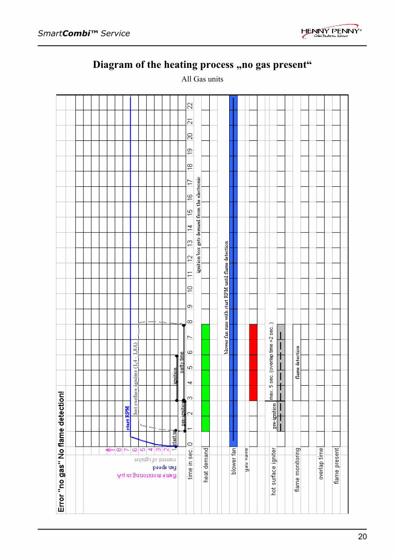
The flame controlThe flame control induces an ionization current (approx. 5 µA) after the igniting process and passes this to the burner control. If this confirmation is not available, the error message "no gas" appears and a reset of the burner control is necessary.
The overlap-timeA sufficient overlap-time is important to ensure or a safety ignition process. This time can be controlled in the generally measurement mask. When heating request of the temperature regulator is available, the display changes from G0 to G1.At first F0 is still shown because there is no flame detected. At latest after 7 seconds F1 must shown on display, otherwise appears the error message "no gas".If the "flame OK" signal is permanently not available the unit goes into an emergency program, because there no safety risks represents.In this case F0 does not change to F1 into the measurement mask, even though the flame is present (The unit heats up). There is only a risk / error, if within the heat demand (active operating) the "flame OK signal" changes repeatedly from F1 to F0.
18

SmartCombi™ Service
Diagram of the heating process „regular operating“All gas units
19
SmartCombi™ Service
Diagram of the heating process „no gas present“All Gas units
20

SmartCombi™ Service
Diagram of the heating process „gas present, no flame detection“All Gas units
21
SmartCombi™ Service
CO2 Gas value calibration6.x–20.x
BasicsDefinition of CO2 (carbon dioxide) and CO (carbon monoxide):
Carbon dioxide is a colourless and odourless gas and supplies a chemical union made of carbon and oxygen. Carbon dioxide arises at the burning of substances containing carbon (gasses) if enough oxygen is available. At an oxygen deficiency CO (carbon monoxide) arises.
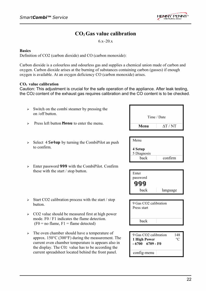
CO2 value calibrationCaution: This adjustment is crucial for the safe operation of the appliance. After leak testing, the CO2 content of the exhaust gas requires calibration and the CO content is to be checked.
➢ Switch on the combi steamer by pressing the on /off button.
➢ Press left button Menu to enter the menu.
➢ Select 4 Setup by turning the CombiPilot an push to confirm.
➢ Enter password 999 with the CombiPilot. Confirm these with the start / stop button.
➢ Start CO2 calibration process with the start / stop button.
➢ CO2 value should be measured first at high power mode. F0 / F1 indicates the flame detection. (F0 = no flame, F1 = flame detected)
➢ The oven chamber should have a temperature of approx. 150°C (300°F) during the measurement. The current oven chamber temperature is appears also in the display. The C02 value has to be according the current spreadsheet located behind the front panel.
22
Time / Date
Menu ∆T / NT
Menu
4 Setup 5 Diagnosis
back confirm
Enter password
999back language
9 Gas CO2 calibration Press start
back
9 Gas CO2 calibration 148 1 High Power °C - 6700 6709 - F0
config-menu

SmartCombi™ Service
➢ Afterwards change to the low power mode by pushing the CombiPilot button. The C02 value has to be according the current spreadsheet
➢ With floor standing units, you can switch between the upper and the lowerchambers with the select button Change chamber. The selected chamber is indicated by anarrow next to the gas fan speed.
If the measured value differs from the values given in the table, the CO2 content must be adjusted to match the values given in the orifice spreadsheet. Unscrew the cap [1] on the gas valve and adjust theCO2 content using the adjustment screw behind it during low power operation.
If the low power CO2 value has been changed, the high power value should be checked and if necessary readjusted. Adjust the CO2 content using the adjustment screw [2].In general an adjustement on the high power screw is not needed, because this value is well-defined by the gas orifice
Preset information:Connect a digital pressure gauge to the gas valve outlet port before starting the calibration process. Change to “low power” and adjust the plastic screw on the gas valve [1] until the outlet pressure is slightly negative at approx -0.2mbar (-20Pa) and start with the CO2 adjustment afterward. This is especially important after converting the oven to a different gas type as the gas valve setting is likely to be significantly out of range. Note, that the pre-adjustement by gas pressure is only to speed up the calibration process! It will not replace the calibration!
Please see also the installation manual for all safety notes and advises!
23
9 Gas CO2 calibration 148 1 Low Power °C - 6700 6709 - F0 0 0 - F0
config-menu Change chamber

SmartCombi™ Service
Gas orifices and fan speeds CSA
24

SmartCombi™ Service
Gas orifices and fan speeds CE
25

SmartCombi™ Service
Internal gas supply check6.x– 20.x
Leakage testPrior to checking the connection pressure, all connection points both outside and inside theappliance must be checked for leaks according to the technical regulations governing gas installations(TRGI) (using a gas detector or leak spray).
Internal gas supply check of the gas blower
➢ Close the on site gas valve.
➢ Disconnect the unit from the power supply (remove fuses or pull the connection-plug)
➢ Unscrew the two screws which are located down on the left to remove the left side panel.
➢ Unscrew the sealing screw from the pressure measurement connection on the gas valve „OUT“ and connect a manometer. The manometer used should be accurate to at least 0.1 mbar.
➢ Open the on site gas valve and connect power supply.
➢ Sart up the appliance.
➢ If the gas blower runs on start speed and the gas valve is still closed, a negative pressure of approx. 3 mbar must be there. The gas blower blast air and the Venturi becomes a negative pressure.
➢ After opening of the gas valve the negative pressure breaks in. A small negative pressure of approx.. < 0,5 mbar persists.
➢ After measuring the pressure and with the shut-off valve still closed, refit the sealing screw in the pressure measuring point and check for leaks.
26
Use only TGRI-approved, foam forming agents! Do not spray leak spray onto the wires of the ignition electronics!
Gage connection „IN“
Gage connection „OUT“
SmartCombi™ Service
Check-up of the connection pressure (operating pressure)6.x–20.x
Leak testPrior to checking the connection pressure, all connection points both outside and inside theappliance must be checked for leaks according to the technical regulations governing gas installations(TRGI) (using a gas detector or leak spray).
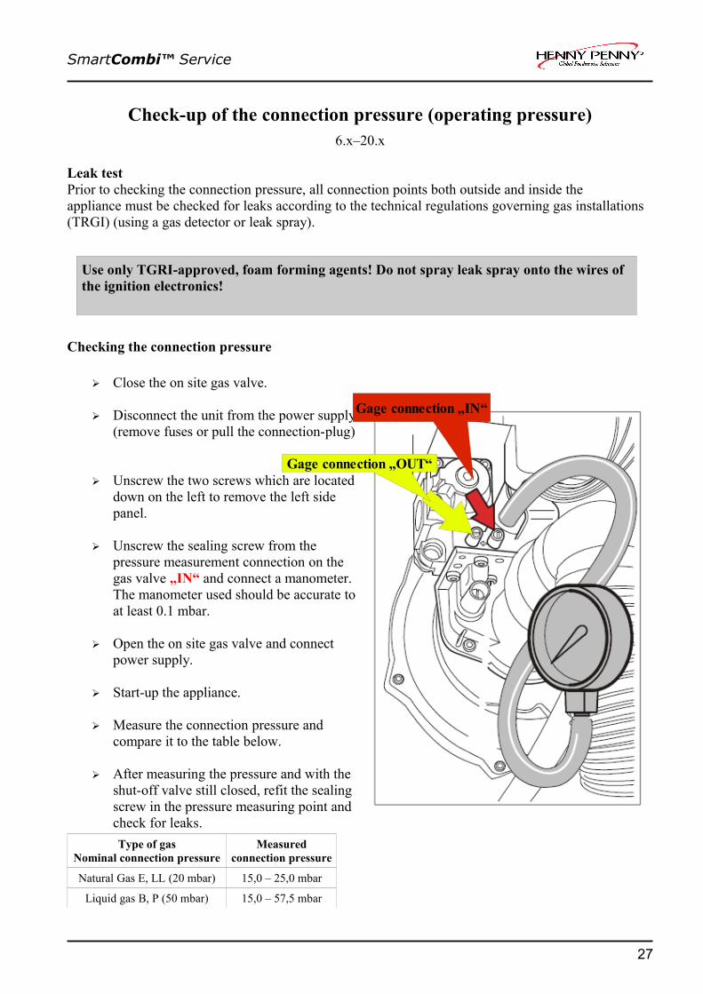
Checking the connection pressure
➢ Close the on site gas valve.
➢ Disconnect the unit from the power supply (remove fuses or pull the connection-plug)
➢ Unscrew the two screws which are located down on the left to remove the left side panel.
➢ Unscrew the sealing screw from the pressure measurement connection on the gas valve „IN“ and connect a manometer. The manometer used should be accurate to at least 0.1 mbar.
➢ Open the on site gas valve and connect power supply.
➢ Start-up the appliance.
➢ Measure the connection pressure and compare it to the table below.
➢ After measuring the pressure and with the shut-off valve still closed, refit the sealing screw in the pressure measuring point and check for leaks.Type of gas
Nominal connection pressureMeasured
connection pressure
Natural Gas E, LL (20 mbar) 15,0 – 25,0 mbar
Liquid gas B, P (50 mbar) 15,0 – 57,5 mbar
27
Use only TGRI-approved, foam forming agents! Do not spray leak spray onto the wires of the ignition electronics!
Gage connection „IN“
Gage connection „OUT“

SmartCombi™ Service
Rearrangement of the gas type 6.x–20.x
To convert to another gas type, the burner restrictor must be changed. The restrictors with a restrictortable are stored in a plastic bag behind the left side wall.
➢ Close the on site gas valve.
➢ Disconnect the unit from the power supply (remove fuses or pull the connection-plug)
➢ Unscrew the two screws which are located down on the left to remove the left side panel.
➢ Unscrew the three screws of the gas valve.
➢ Remove gas valve.
➢ Remove gas restrictor with the seal [1]
➢ Select a restrictor with the help of the table and refit it by using an undamaged seal. [2].
➢ Set up and mount the gas valve.
➢ Open the on site gas valve.
➢ Switch on the power supply
➢ After the conversion continue with leak testing, checking of the connection pressure and calibration of the CO2/CO-values.
28
SmartCombi™ Service
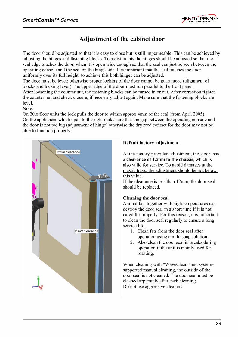
Adjustment of the cabinet door
The door should be adjusted so that it is easy to close but is still impermeable. This can be achieved by adjusting the hinges and fastening blocks. To assist in this the hinges should be adjusted so that the seal edge touches the door, when it is open wide enough so that the seal can just be seen between the operating console and the seal on the hinge side. It is important that the seal touches the door uniformly over its full height; to achieve this both hinges can be adjusted.The door must be level; otherwise proper locking of the door cannot be guaranteed (alignment of blocks and locking lever).The upper edge of the door must run parallel to the front panel.After loosening the counter nut, the fastening blocks can be turned in or out. After correction tighten the counter nut and check closure, if necessary adjust again. Make sure that the fastening blocks are level. Note:On 20.x floor units the lock pulls the door to within approx.4mm of the seal (from April 2005).On the appliances which open to the right make sure that the gap between the operating console and the door is not too big (adjustment of hinge) otherwise the dry reed contact for the door may not be able to function properly.
Default factory adjustment
At the factory-provided adjustment, the door has a clearance of 12mm to the chassis , which is also valid for service. To avoid damages at the plastic trays, the adjustment should be not below this value.If the clearance is less than 12mm, the door seal should be replaced.
Cleaning the door sealAnimal fats together with high temperatures can destroy the door seal in a short time if it is not cared for properly. For this reason, it is important to clean the door seal regularly to ensure a long service life.
1. Clean fats from the door seal after operation using a mild soap solution.
2. Also clean the door seal in breaks during operation if the unit is mainly used for roasting.
When cleaning with “WaveClean” and system-supported manual cleaning, the outside of the door seal is not cleaned. The door seal must be cleaned separately after each cleaning.Do not use aggressive cleaners!
29
12mm clearance
12mm clearance

SmartCombi™ Service
Overview and compatibility summary of temperature probes
Overall summary of original probes
MKN No. description 6.23 6.1 6.2 10.1 10.2 20.1 20.2203697 CT- probe 760 mm long, 4 point + + + + + - -203688 CT- probe 1160 mm long, 4-point - - - - - + +203689 Chamber probe 3200 mm long,
black shrink hose.- + + + + + +
203991 Humidity probe (gold) chamber probe (Junior) 1600 mm long, yellow or transparent shrink hose.
+ + + + + + +
203693 Vapour probe1500 mm long, green silicon coating.
+ + + + + - -
203990 Vapour probe2150 mm long, green silicon coating.
- - - - - + +
.
Compatibility summary
- - 6.23 6.1 6.2 10.1 10.2 20.1 20.2Humidity probe
original 203991 203991 203991 203991 203991 203991 203991
alternative 203689* 203689 203689 203689 203689 203689 203689Vapour probe original 203693 203693 203693 203693 203693 203990 203990
alternative 203990 203990 203990 203990 203990 - -
- Note: After installation the sensor typ #203689 on junior must be bent 180° upwards.
Note: There is a danger of confusion when replacing with an alternative sensor, because the colour markings are then not correct and it can be confusing at the plug. Please mark the sensor accordingly at the plug and after installing check that it has been correctly installed.
30

SmartCombi™ Service
Description of the frequency controller
ff
Demontage:
Sample on a 1-phase (90Veff – 264Veff) controller
Installation instructions
Disconnect the unit from the power and gas supply. Wait at least 3 minutes until the capacitors on the controller have unloaded themselves!
The frequency converter is fitted with a wide range input. The input voltage can be configured with the link plug (Jumper) J1 Input voltage at the mains terminal inlet can be measured according to the following Jumper status.To be measured are:J1 Plugged: Area 200V-240V (-10%, +15%) Despatch status!!!J1 Open : Area 100V-120V (-10%, +15%)The voltage (live) phase L must be led through the Ferrite core before the mains terminal in the cable harness, to avoid EMC-interferences in the appliance.
For the appliance sizes 6.1, 10.1 and 20.1 the Jumper J3 is not plugged (open, despatch status). Therefore the Jumper must be plugged between J3 and J4 (horizontally). The fan runs max.. 1500 rpm´s.In the appliance sizes 6.2, 10.2 and 20.2 the Jumper J3 must be plugged (left Jumper vertically). The fan runs max. 1800 rpm`s
31
J1
J3 J4
LED
Jumper settings for operational voltage
Plugged = 230V ConfigurationOpen = 115V Configuration
Default setting:230V configuration
Jumper settingsfor fan
motor speed
SmartCombi™ Service
Continuation frequency controller descriptionFunctional test
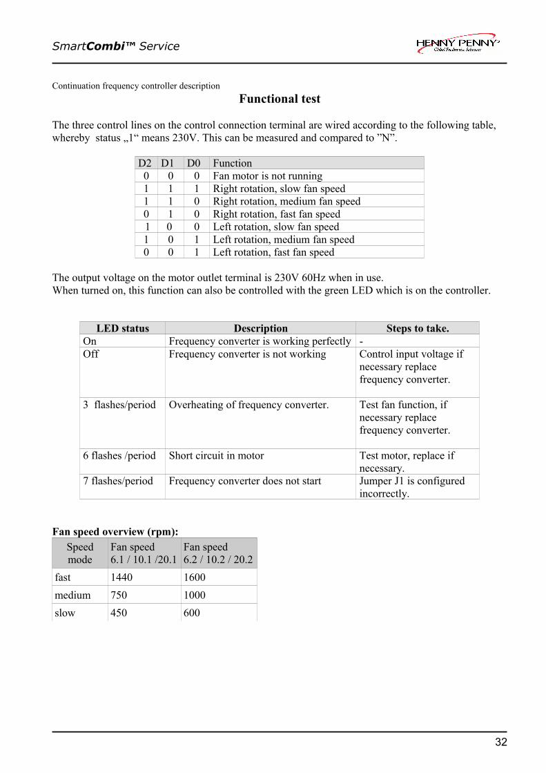
The three control lines on the control connection terminal are wired according to the following table, whereby status „1“ means 230V. This can be measured and compared to ”N”.
D2 D1 D0 Function0 0 0 Fan motor is not running1 1 1 Right rotation, slow fan speed1 1 0 Right rotation, medium fan speed 0 1 0 Right rotation, fast fan speed 1 0 0 Left rotation, slow fan speed1 0 1 Left rotation, medium fan speed0 0 1 Left rotation, fast fan speed
The output voltage on the motor outlet terminal is 230V 60Hz when in use.When turned on, this function can also be controlled with the green LED which is on the controller.
LED status Description Steps to take.On Frequency converter is working perfectly -Off Frequency converter is not working Control input voltage if
necessary replace frequency converter.
3 flashes/period Overheating of frequency converter. Test fan function, if necessary replace frequency converter.
6 flashes /period Short circuit in motor Test motor, replace if necessary.
7 flashes/period Frequency converter does not start Jumper J1 is configured incorrectly.
Fan speed overview (rpm):Speed mode
Fan speed6.1 / 10.1 /20.1
Fan speed6.2 / 10.2 / 20.2
fast 1440 1600medium 750 1000slow 450 600
32

SmartCombi™ Service
The main menu (Password overview & diagnosis memory)
01.01.2015 5:55
Menu
33
1. Manual cleaning
2. WaveClean
3. HACCP
4. Setup
5. Diagnosis
6. Cookbook -> USB
7. USB -> Cookbook
Half automatic cleaning program with presetted steps. If the cooking chamber is too hot, the appliance will be cooled automatically. If it is too cold, it is heated to the soaking temperature. Further actions(spraying cleaner, rinsing) are displayed at the respective time.
Automatic cleaning system. Three programs can be selected: (short approx. 1 hour; normal approx. 2 hours; extra approx. 3 hours)
The unit saves up to 200 HACCP logs, depending on the number of program steps. The logs can be transmitted to the USB-port (from software 4.00; S/N 09021482; July 2009)
Password for basic adjustments: 111If the password for settings area is unknown, the area can be also entered by pushing the CombiSteam and Preheat button at the same timePassword for service area :777 Enter password with the Combi dial and confirm by pushing Start/ Stop button.
The diagnosis memory saves current and former error messages. These are represented historically according to the date and time. Turn the Combi dial to scroll inside the diagnosis memory.
Up- and download of recipes to / from a USB stick. Only available at units with USB-port (from software 4.00; S/N 09021482; July 2009)

SmartCombi™ Service
Service menu of the electronic (Configuration menu)
The service menu (configuration menu) serves for the check and analysis of all electronic components. These can be test one by one or by summarized test programs. If once the flash module should be exchanged, then this must be configured completely. In this case all steps must be carried out as well as a petition of equipment specific information is necessary. A module preprogrammed by MKN can alternatively be installed. In this case the serial number must be announced with the order.
Access the configuration menu as follows:- Select menu on the left select button- Select 4 setup with the CombiPilot- Push CombiPilot- Enter password 777 with the CombiPilot (enter number, push CombiPilot, enter next number) and confirm with “start/stop”- Select test step and confirm with the CombiPilot.
34
Leftselect button
Rightselect button
SmartCombi™ Service
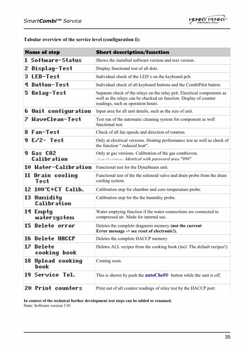
Tabular overview of the service level (configuration I):
Name of step Short description/function
1 Software-Status Shows the installed software version and text version .
2 Display-Test Display functional test of all dots.
3 LED-Test Individual check of the LED´s on the keyboard pcb.
4 Button-Test Individual check of all keyboard buttons and the CombiPilot button.
5 Relay-Test Separate check of the relays on the relay pcb. Electrical components as well as the relays can be checked on function. Display of counter readings, such as operation hours.
6 Unit configuration Input area for all unit details, such as the size of unit.
7 WaveClean-Test Test run of the automatic cleaning system for component as well functional test.
8 Fan-Test Check of all fan speeds and direction of rotation.
9 E/2- Test Only at electrical versions. Heating performance test as well as check of the function " reduced heat".
9 Gas CO2 Calibration
Only at gas versions. Calibration of the gas combioven. See also CO2 Calibration. Identical with password area "999"
10 Water-Calibration Functional test for the DynaSteam unit.
11 Drain cooling Test
Functional test of the the solenoid valve and drain probe from the drain cooling system.
12 100°C+CT Calib. Calibration step for chamber and core temperature probe.
13 Humidity Calibration
Calibration step for the the humidity probe.
14 Empty watersystem
Water emptying function if the water connections are connected to compressed air. Made for internal use.
15 Delete error Deletes the complete diagnosis memory (not the current Error message -> see reset of electronic!).
16 Delete HACCP Deletes the complete HACCP memory
17 Delete cooking book
Deletes ALL recipes from the cooking book (incl. The default recipes!).
18 Upload cooking book
Coming soon.
19 Service Tel. This is shown by push the autoChef® button while the unit is off.
20 Print counters Print out of all counter readings of relay test by the HACCP port.
In context of the technical further development test steps can be added or renamed. State: Software version 3.01
35

SmartCombi™ Service
Detailed description of the service area
1 Software-Status
The software versions of the• Booter • Application (software version)• Text list
are displayed.The application version is important for equipment functionality. Application = software
2 Display-Test
Test patterns appear in the following cycle:• Fully activated• Chess board 1• Chess board 2• Fully de-activated
Pressing the CombiPilot button allows the individual steps to be accessed. When completed finished appears on the display.
3 LED-Test
The “ON” LED does not need to be tested, because it is already switched on. The remaining 5 LED´s (4 cooking modes and start/stop) are tested by repeated pressing of the combi-pilot. When completed finished appears on the display.
4 Button-Test
In the button test all buttons are pressed one after the other (including the select-buttons and the CombiPilot). CAUTION: Do not start with the “ON/OFF” button. Only after all buttons have pressed once it is possible to return to the configuration menu. When completed finished appears on the display.Every button is confirmed by the accompanying number on the display. If a button should be faulty the power supply must be switched off, because a return from this test is not possible anymore.
36

SmartCombi™ Service
5 Relay Test + Counter readings
A menu is offered with all relays of the relay pcb (K01 - K24). By pushing the CombiPiloten the current condition of the chosen relay is switched over. This can be checked with the LED next to each relay. The LED signals the status on the input side of the relay (LED on = energized, LED off = not energized). The load side (output) can be controlled by measuring the outcoming voltages on terminal X5 and X6. Caution! During this test the reed contact-switch for the door is out of order! By a configuration of a new flash module a test of all relays is not required.
After the relay has selected, it can be checked by pressing the CombiPilot. A counter of each relay (down on the right) is shown on the display in addition. A reset of the counter is not possible.
Actor Name of step Description/ function if pushing the CombiPilot button
K01 Main contactor The relay is switched on about X6.2 and can not be switched over (the unit would switches off itself ).
K02 FC D0 / Fan 1 Input D0 on the frequency converter becomes a 230V signal about X5.3. The fan motor starts on the left direction in fast speed mode.
K03 FC D1 / Fan 2 Input D1 on the frequency converter becomes a 230V signal about X5.5. The fan motor starts on the right direction in fast speed mode.
K04 FC Fan 2 / l/r Contactor K3 is energized by X5.7. The upper fan is added-on (Only 20.x)
K05 FC D2 / Fan s/l
Input D2 on the frequency converter becomes a 230V signal about X5.9. The fan motor starts on the left direction in slow speed mode.
K06 Illumination The relay turns the chamber illumination off/on by X5.2.K07 Cooling fan The relay switches the cooling fan on/off by X5.10.K08 Freash air pipe The relay energizes the lift-magnet (fresh air flap) by X6.3 (via
rectifiers V8).K09 Ext. Hood Contact for an external hood (Contact closes for 60 seconds after
opening the door). K10 Solenoid steam 1 Energizing of the DynaSteam unit by X8 (not from a relay)K11 Solenoid steam 2 Energizing of the DynaSteam unit by X8 (not from a relay)K12 Solenoid drain
coolingThe relay switches on the solenoid valve Y12 by X6.6 for drain cooling.
K13 Signal The relay switches on the buzzer H13 by X5.13.K14 Gas On 1 Energizes signal board N11 / ignition box N10 by X6.10.
The ignition electrode R10 glows up (Only Gas).K15 Gas On 2 Energizes signal board N21 / ignition box N20 by X6.11.
The ignition electrode R20 glows up (Only Gas)(Only 20.x).
37

SmartCombi™ Service
Continuation relay test
Actor Name of step Description/ function if pushing the CombiPilot button
K16 Pump WaveClean The relay switches on the pump M16 by X6.12. The water is pumped out of the trap into the chamber. Caution! Only carry out this step if the chamber cooled down!
K17 Reserve Relay --> see documentation reserve relay
K18 n.u. - not in use -
K19 n.u. - not in use -
K20 LOA B Output for the connection of an energy optimization system (terminal X2/B).
K21 Pot. free. LOA (only at electric units)
Potential free contact for an energy optimizing system (terminal X2.15 and X2.16)
K21 Gas Reset 2 (only at gas units)
Reset Signal from X5.15 to ignition box N20 (Only at 20.x)
K22 Door lock (only at electric units)
- not in use for this units -
K22 Gas Reset 1 (only at gas units)
Reset Signal from X5.17 to ignition box N10
K23 n.u. - not in use -
K24 Pump Siphon (trap)
The relay switches on the pump M24 by X6.9. The water is pumped out of the trap into to drainage.
Counter readings in the relay test:
Hours electronic Connected hours on the power supply. Hours unit on Hours which the device was in standby.Hours cooking Hours of operatingPowerfail Number of powerfails (longer than 10 sec.) during operation.
38

SmartCombi™ Service
6 Unit configuration
The following steps must be adjusted by the service engineer only at a new configuration of the flash modul.
Step Parameter Value range Comment6-1 Unit size/type 6.1;6.2;10.1;10.2;20.1;
20.2;6.23 (Junior)Adjustment of the unit size
6-2 Heating source electric, gas Adjustment of the heating source6-3 M.-Nr. (unit no.) each 0-9 Enter the no. by turning the CombiPilot;
Confirmation of each number by pushing the CombiPilot. Finally confirmation by pressing the start/stop button..
6-4 WaveClean On / Off Activation / deactivation WaveClean. Default „on“6-5 CT 4x On / Off Multi-point core temperature probe On / Off. “Off”
= single-point Defaul setting „on“
6 PID-Parameter - Not in use6 Fan motor type Contactor 2 speed (HansDampf
6.1;10.1;20.1 contactors controlled)Contactor 1 speed(only 6.23 (Junior)FC 2 speeds(all units with 2 speed frequency fan controller)FC 3 speeds (all units with 3 speed frequency fan controller)
Adjustment of the fan motor type. Default setting „FC 3 speeds.
PHI DynaSteam On / Off On = soft water assembly with steaming unitOff = soft water assembly with pressure reducer and solenoid valve. Default setting „on“
RackControl On/ Off Activation / deactivation RackControl.Default setting „on“
6-6 Function code - Not in use
7 WaveClean Test
Press start appears on the display. Push the Start/ Stop button or the CombiPilot to start the WaveClean test. The pump M24 pumps out the water from the trap. The trap gets filled with water by the solenoid valve Y12. This process repeats two times. The pump M16 and also fan M1 / M2 (only 20.x) switches on and cycles the water from the trap permanently. The test can be interrupt by cancel any time. At the end of the test the trap is pumped out and filled again twice.
39

SmartCombi™ Service
8 Fan Test
A menu with the following fan modes is offered:➢ Right slow➢ Right medium➢ Right fast➢ Left slow➢ Left medium➢ Left fast
Push the CombiPilot to start with right slow. The fan speed and direction is shown on the display during the fan runs. To change an other fan mode turn the CombiPilot and push the CombiPilot to confirm. Push left select button configuration menu to go back in the service area.
Explanation:
9 E/2- Test (only at electric units)
The following menu is displayed:- E/2 (half heating power)- E (full heating power)
Press the CombiPilot to start the E/2 mode. On units 6.x and 10.x only one heating circuit is activated, on the20.x the lower heating circuit is completely switched off. E-mode can selected by turning CombiPilot to left. All heating circuits are supplied now (Complete heating power).
9 Gas CO2 Calibration (only at gas units)
Calibration of the gas CO2 values. See CO2 Calibration. Identical with password area "999"
40
Fan speed (rpm) and direction of fan 1
Push „config menu“ to go back in the service area
Fan speed (rpm) and direction of fan 2 (only 20.x)
Selection area for fan mode

SmartCombi™ Service
10 Water calibration
Push the CombiPilot to start.140 ml of water coming through the water supply pipe into the chamber now. At the unit size 20.x both DynaSteam units are energized at the same time. This steps allows to check the function of the DynaSteam unit. The amount of water can be control with a measuring box. A deviation of +10 ml is within the possible tolerance. A calibration is not possible/necessary because this component is complete controlled by the electronic.If the CombiPilot is pushed once more, 140 ml are added up on the value on the display and another 140 ml run through the water water supply pipe.
11 Drain cooling test
The display shows the current drain temperature. Push the CombiPilot to start test. Push and hold right select button Drain cooling . The manually cooling function starts and the drain temperature drops down.
12. 100 C + CT probe calibration°
Caution! The CT probe and an external sensor (from temperature measuring meter) must be located in the centre of the cooking chamber.We recommend that the sensor is hung on the grill grid. The sensor tip must point upwards in order to avoid drops forming on the sensor tip. The following values are shown on the display:
At one-chamber units (6.x / 10.x):
At two chamber units (20.x):
41
Current chamber temperature
Turn on time of heating circuit.(max. 1000 = 100%)
Temperature-Offsetin 0,1 °K – steps
Back to service menu
Current chamber temperature 1(lower probe)
Turn on time of both heating circuit.(max. 1000 = 100%)
Temperatur-Offset for the upper heating circuit / probe in 0,1 °K – steps
Temperature-Offset for the lower heating circuit / probe in 0,1 °K – steps
Back to service menu Selection between upper and lower chamber
Current chamber temperature 1(upper probe)

SmartCombi™ Service
Continuation probe calibration
For one and two-chamber units:Pressing the Combi-Plot starts the 100 °C (212°F) calibration. Before setting the offset factor for the first time, wait at least 30 minutes. When the current probe temperature shows 100 °C (± 1°C) on the display and the external temperature sensor indicates a value of between 99 °C and 99.5 °C, the unit is correctly calibrated. If the external device does not reach the temperature range specified, the temperature offset should be adjusted accordingly by turning the CombiPilot. Caution! After any change to the offset setting, always wait approx. 10 minutes to allow the change to affect the cooking chamber temperature (temperature on external temperature sensor should remain stable).Only at two-chamber units (20.x):In the case of two-chamber units, the right select button (chamber selection) can be used to switch between both offset values. During the offset measurements, the chambers must separated from each other (with a baking tray for example). The upper and lower probes now have to be calibrated separately. To carry out this, use two external temp. probes, one placed in the upper chamber centre and the other in the lower chamber centre . We recommend an external temperature measurement meter using two temperature sensors (or a dual-channel unit). Always ensure the calibration is performed such that both chambers have an approximately equal contribution. This can be checked on the value of the heat time (Turn on time). These displays should show approximately the same value.For all units: When the actual temperature is at 100 °C ± 1 K, the core temperature sensor is automatically also calibrated when the calibration is finalised. If the actual temperature is outside of the specified tolerance, the following message appears: KT sensor not calibrated. For finishing the calibration press the left select button cancel .
13 Humidity calibration
The unit is heated for 8 minutes at 180°C (356°F). The ventilation flap opens and the values measured by the humidity sensor are automatically saved as calibration settings. Caution! Please wait until the message finished appears on the display.
14 Empty water system
This step serves to empty the water inside (like valves and hoses) the system. The unit has connected to air pressure at both water connections. Now the program has to be started.This program step was conceived to avoid frost damages while transportation and is basically made for internal use.
15 Delete error
Push the right select button delete to delete the complete diagnosis momory. Press the left select key config menu to return to the configuration menu This step should be just executed at a change of ownership of the device to hold a history of all error messages from the past. This program step does not delete current faults but only the diagnostic memory! Current error messages are deleted by a reset of the electronic.
42

SmartCombi™ Service
16 Delete HACCP
On the display appears delete. Press the right select button to delete. Press the left select button config menu to return to the configuration menu. This step should be only done at a change of ownership of the device to delete the whole HACCP documentation.
17 Delete cooking book
On the display appears delete. Press the right select button to delete. Press the left select button config menu to return to the configuration menu. This step should be only done at a change of ownership of the device to delete the complete cooking book including all preprogrammed recipes!
18 Upload cooking book
At present, this program step is for the internal use only.
19 Service Tel.
This function allows to enter a service phone number.Later on the number is shown on the display by push the autoChef® button while the unit is off.
20 Print counters
All counter readings are (below the front panel) distributed by pressing the CombiPilot at the serial interface.
43

SmartCombi™ Service
Settings area (basic settings)
The HansDampf electronics are set to standard parameters on delivery. These standard parameterscan be changed individually within defined limits.
To enter the settings area the following steps have to be carried out: • Turn on the unit.• Push the left soft button Menu. • Select 4 Setup by turning the Combi dial. • Confirm by pushing the Combi dial. • Enter password 111 with the Combi dial (enter number, push Combi dial, enter next number)• and confirm with “start/stop”.• You are now in the settings area. With the Combi dial the desired step can be chosen. By pushing
the Combi dial this is selected.
44
Leftselect button
Rightselect button

SmartCombi™ Service
Description No. Setting range Explanation / function Time / Date 000 Time and date Push Combi dial button to change time
& date. Push Combi dial = selection Turn Combi dial = Change value
Temperature reading in
006 °C / °F Adjustment between temperature readings in °C or °F
Illumination blinking
023 On / Off (default = On)
Illumination flashes at the end of a program (in addition with the buzzer)
Preheat factor % 082 0 – 30 % (default =15 % )
Preheat factor if using “ready2cook“. The factor will added to the selected temperature (example: 100°C adjusted = preheating up to 115°C). This happens under consideration of the maximum temperature values.
Water maintenance liter
076 0 – 90000 liter in 100 liter-steps
(default = 0 (Off))
Attitude of the water softener capacity. Only the following situations possible:
– Separate water softener for the unit – Only the soft water connection is
connected at the filter. After the adjusted water quantity has flowed through the DynaSteam unit, a maintenance request appears on the display.
Format of date 144 Change of the shown format of date
12/24 hour reading
TT = day MM = month JJJJ = year 12 = 12 hour reading24 = 24 hour reading
Cookbook 097 Open / Locked / Fully locked
(default = open)
Open: Saving, changing & deleting of recepis in cooking book possible. Locked: Saving, changing & deleting of recepis in cooking book not possible. However, changes are possible after selecting recipe (before operation). Fully locked: Similar to „locked“, but no changes possible after selecting recipe (before operation).
45

SmartCombi™ Service
Description No. Setting range Explanation / function
Time delay fan 032 Off / On (default = off)
Push Combi dial button to change setting.Push Combi dial = selection Turn Combi dial = Change value When "On", the fan runs during thetime delay to cool the oven chamberwith a block of ice in the bottomdrawer.For this purpose, place the perforatedcontainer in the closed container, fillwith approximately 4 litres of waterand allow to freeze. Insert the iceblock into the perforated container atthe lowest level. This allows atemperature of 14°C to be maintainedfor up to 6 hours.
Cooling water 024 Minimal / Normal / Maximal (default = normal)
Setting minimal: Less water consumption but higher drain temperature and more steam from the exhaust pipe.Setting maximal: More water consumption but lower drain temperature and less steam from the exhaust pipe.
Time ext. hood 083 0 – 600 seconds (default = 60 seconds)
Time where the external condensation hood runs to maximum performance after the chamber door was opened.
Time signal (s) 084 0 – 180 seconds (default = 20 seconds)
Time of the buzzer/ flashing illumination at the end of a program.0= buzzer off. In addition to the buzzer the flashing illumination can deactivated / activated. See also parameter 023.
Altitude 015
0-500 m; 501 – 1000 m; 1001 – 1500 m; > 1500 m (default = 0)
Altitude adjustment (above sea level).
Password 096 000 – 500 (default = 111)
Individual passwords can be set up inthis here.
Scroll direction 225 Normal / Clockwise (default = normal=)
The direction of the Combi dial can beadjusted as required in the menus andcookbook.
46

SmartCombi™ Service
Description No. Setting range Explanation / function
Temp. Steam 235 30 – 130 °C (86 - 266°F)(default = 100°C, 212°F)
Temp. Combi 236 30 – 250 °C (86 - 482°F)(default = 130°C, 266°F)
Temp. Convection 237 30 – 300 °C (86 - 482°F)(default = 180°C, 358°F)
Temp. Perfection 238 30 – 180 °C (86 - 356°F)(default = 120°C, 248°F)
Temp. LTC 239 60 – 100 °C (140 - 212°F)(default = 60°C, 140°F)
Temp. Delta 240 1 – 100 °C (34 - 212°F)(default = 20°C, 68°F)
Temp. DT-Core 241 30 – 99 °C (86 - 210°F)(default = 60°C, 140°F)
The default temperatures can beindividually set up for the cookingprocess within the limits shown here
Cooking book history 242 0 – 10
(default = 10)
With the history function the last used programmes from the cooking book memory can be displayed (Push Smart Menu -> history)
Default category 397
Cooking book; Meat, Poultry, Fish, Vegetables, Side dishes, Bakery products, Overnightcooking, MyChef – Special;Perfection(default = Cooking book)
Cooking book no. 403
0: Only your own recipes1: German2: English GB3: Italian4: French5: Dutch6: Spanish7: Polish8: Danish9: Russian10: Czech11: Lithuaniab12: Lativan22: Turkish100: HennyPenny english
Different country-specific cookbooks can beloaded via cookbook switching. Deleted Auto-Chef cooking programs can also be restoredhere. For this purpose, select cookbooknumber and then save. Press "Save" afterswitching the cookbook. "analysis" appearsfor up to 5 minutes. Cooking programs created on the appliance remain when the cookbook is changed.
For further information and languages see also operation manual!
Finally push the select button save to save changes or push back to leave the settings area without saving any changes.
47

SmartCombi™ Service
Generally measurement mask for electric units
This mask shows you a summary of measurement information during preheating and cooking process.
By press and hold the combi pilot during operation for a short time, you can see the following information until pushing the the left soft key „back“.
6.x / 10.x
48
chamber temperature [°C/°F]
Fan speed [ rpm] and fan direction
Heat demand [%] Electronic temperature
Temperaturedrain probe
Core temperatures 1-4.
Fresh air pipe demand Z0= close Z1= open
Water injection(steam)demand B0= Off B1= On
Drain coolingdemand W0= Off W1= On

SmartCombi™ Service
20.x
The measurements are updated circular. A short delay of the displayed information is therefore possible. Broken (disconnected) probes could be shown at the mask with “999”.
49
chamber temperature [°C/°F] - upper chamber - lower chamber
Fan speed [ rpm] and fan direction - upper chamber - lower chamber
Heat demand [%] - upper chamber - lower chamber
Electronic temperature
Temperaturedrain probe
Core temperatures 1-4
Fresh air pipe demand Z0= close Z1= open
Water injection(steam)demand B0= Off B1= On
Drain coolingdemand W0= Off W1= On
SmartCombi™ Service
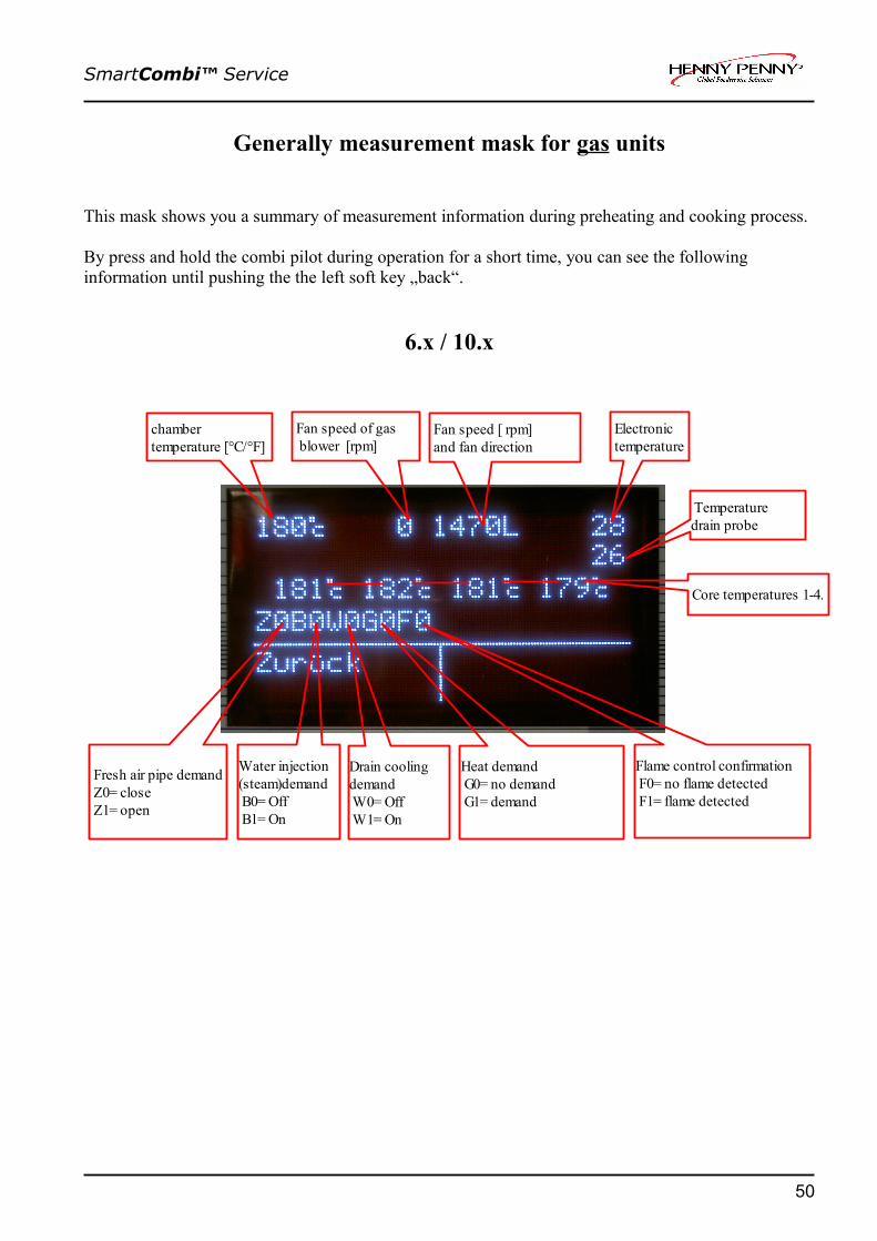
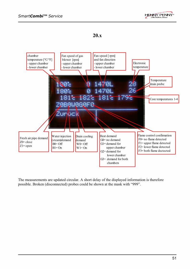
Generally measurement mask for gas units
This mask shows you a summary of measurement information during preheating and cooking process.
By press and hold the combi pilot during operation for a short time, you can see the following information until pushing the the left soft key „back“.
6.x / 10.x
50
chamber temperature [°C/°F]
Fan speed [ rpm] and fan direction
Fan speed of gas blower [rpm]
Electronic temperature
Temperaturedrain probe
Core temperatures 1-4.
Fresh air pipe demand Z0= close Z1= open
Water injection(steam)demand B0= Off B1= On
Drain coolingdemand W0= Off W1= On
Heat demand G0= no demand G1= demand
Flame control confirmation F0= no flame detected F1= flame detected
SmartCombi™ Service
20.x
The measurements are updated circular. A short delay of the displayed information is therefore possible. Broken (disconnected) probes could be shown at the mask with “999”.
51
chamber temperature [°C/°F] - upper chamber - lower chamber
Fan speed [ rpm] and fan direction - upper chamber - lower chamber
Fan speed of gas blower [rpm] - upper chamber - lower chamber
Electronic temperature
Temperaturedrain probe
Core temperatures 1-4
Fresh air pipe demand Z0= close Z1= open
Water injection(steam)demand B0= Off B1= On
Drain coolingdemand W0= Off W1= On
Heat demand G0= no demand G1= demand for upper chamber G2= demand for lower chamber G3= demand for both chambers
Flame control confirmation F0= no flame detected F1= upper flame detected F2= lower flame detected F3= both flame dectected

SmartCombi™ Service
How to activate and disable the demo mode
Activate demo mode:Press & hold the ON / OFF button for 16 seconds during the appliance is switched off. The unit changes now into the demo mode
Disable demo mode:Press & hold the ON / OFF button for 16 seconds during the appliance is switched off. The unit changes now back into the normal (operation) mode.
Reset of the electronic
Press & hold the ON / OFF button for 8 seconds during the appliance is on. The electronic resets now. After 8 seconds “Loading Flash data” appears on the display. The electronic transmits the data’s from the flash modul to the RAM.
Connecting a performance optimization system (LOA)
Connection
Connect the performance optimization system on the terminal behind the front panel.Remove the bridge on terminal X2 between clamp “B” and “C”.Connect the performance optimization cable at clamp “B” and “C”The cable has to be installed according to the installation instructions. → See also installation manual
How it works
Unit size 6.x / 10.x: (single chamber):If the performance optimization is active, the heating elements are not energized.
Unit size 20.x (two chamber):If the performance optimization is active, just the lower heating element cuts off. So the power input will be cut in half.
Connection of external facilities to the potential-free contact
The connections for the potential-free contact are on the electric assembly behind the front panel (terminal X2, clamp 15 and 16).
52

SmartCombi™ Service
How to change the display language
For changing the display language, please do the following steps:• Switch the unit on by pressing the “ON/Off” button.• Press the left soft key “Menu” • Then select step 4 “settings” with the combi pilot.• If you press the right soft key “Language” you can change the display language with the combi
pilot.• Please confirm the requested language by pressing the right soft key “save”.• Then press the right soft key twice. Now you are back in the main menu
53

SmartCombi™ Service
Layout of relay pcb A1 Electric & Gas CE-Version
X5:No. description fuse on
board1 Input 230 Volt2 Output to SSR V6 illumination F13 Output to D0 at frequency converter F24 -5 Output to D1 frequency converter F26 -
54
A1
X1:Serial RS232 port for software update.
X3:No. description1 Input 21 Volt Electronic supply2 Input 21 Volt Electronic supply3 Input 21 Volt Electronic supply4 Input 4,2 Volt Display supply5 Input 4,2 Volt Display supply
X4:No. description1 -2 Monitoring „safety cut off (230V)3 Monitoring „LOA C“ (230V)(optimisation system)4 Input neutral (N)

SmartCombi™ Service
X5 (continuation):No. description fuse on
board7 Output to K3 (only 20.x)8 Input 230 Volt9 Output to D2 Frequency converter F210 Output to M7 / M7.x(only 20.x) F211 Connection for external exhaust hood (signal contact)12 Connection for external exhaust hood (signal contact)13 Output to buzzer H1314 Input 230 Volt (buzzer supply)15 Output to ignition box N20 (Gas Reset 2) (only 20.x Gas)16 Input 230 Volt from transformer T1 (only 20.x Gas)17 Output to ignition box N10 (only Gas units)18 Input 230 Volt from transformer T1 (only Gas units)
X6:No. description fuse on
board1 Input 230 Volt2 Output to F7 limit switch /main contactor F33 Output to V8 rectifier / Y8 lift magnet F44 - F45 - F46 Output to solenoid valve Y12 F47 Output for Energy optimisation system8 - F49 Output to cleaning pump M24 F410 Output to ignition box N10 (Control signal glow electrode)
(only Gas units)F4
11 Output to ignition box N20 (Control signal glow electrode) (only 20.x Gas units)
F4
12 Output to cleaning pump M16 F413 Output to reserve relay K1714 -15 -16 -
X7:No. description1 Not in use2 Not in use
X8:No. description1 Output signal DynaSteam unit Y10 / Y20 (Y20 only 20.x)2 Output signal DynaSteam unit Y10 / Y20 (Y20 only 20.x)3 Output to signal pcb N11 (only gas)4 Output signal DynaSteam unit Y11 / Y21 (Y21 only 20.x)5 Output signal DynaSteam unit Y11 / Y21 (Y21 only 20.x)9 Output to signal pcb N21 (only 20.x gas)
Fuses: F1: 2A Slow blow #203474; F2,F4: 8A Slow blow #203741; F3: 3,15A Slow blow #203742
55

SmartCombi™ Service
Layout of relay pcb Electric & Gas UL-Version
X5:No. description fuse on
board1 Input 230 Volt2 Output to SSR V6 illumination F13 Output to D0 at frequency converter F24 -5 Output to D1 frequency converter F26 -
56
A1
X1:Serial RS232 port for software update.
X3:No. description1 Input 21 Volt Electronic supply2 Input 21 Volt Electronic supply34 Input 4,2 Volt Display supply5 Input 4,2 Volt Display supply
X4:No. description1 -2 Monitoring „safety cut off (230V)3 Monitoring „LOA C“ (230V)(optimisation system)4 Input neutral (N)

SmartCombi™ Service
X5 (continuation):No. description fuse on
board7 Output to K3 (only 20.x)8 Input 230 Volt9 Output to D2 Frequency converter F210 Output to M7 / M7.x(only 20.x) F211 Connection for external exhaust hood (signal contact)12 Connection for external exhaust hood (signal contact)13 Output to buzzer H1314 Input 24 Volt (buzzer supply)15 Output to ignition box N20 (Gas Reset 2) (only 20.x Gas)16 Input 230 Volt from transformer T1 (only 20.x Gas)17 Output to ignition box N10 (only Gas units)18 Input 230 Volt from transformer T1 (only Gas units)
X6:No. description fuse on
board1 Input 230 Volt2 Output to F7 limit switch /main contactor F33 Output to V8 rectifier / Y8 lift magnet F44 - F45 - F46 Output to solenoid valve Y12 F47 Output for Energy optimisation system8 - F49 Output to cleaning pump M24 F410 Output to ignition box N10 (Control signal glow electrode)
(only Gas units)F4
11 Output to ignition box N20 (Control signal glow electrode) (only 20.x Gas units)
F4
12 Output to cleaning pump M16 F413 Output to reserve relay K1714 -15 -16 -
X7:No. description1 Buzzer supply voltage to X5.142 Buzzer supply voltage
X8:No. description1 Output signal DynaSteam unit Y10 / Y20 (Y20 only 20.x)2 Output signal DynaSteam unit Y10 / Y20 (Y20 only 20.x)3 -4 Output signal DynaSteam unit Y11 / Y21 (Y21 only 20.x)5 Output signal DynaSteam unit Y11 / Y21 (Y21 only 20.x)9 -
Fuses: F1: 2A Slow blow #203474; F2,F4: 8A Slow blow #203741; F3: 3,15A Slow blow #203742
57

SmartCombi™ Service
Layout of keyboard pcb A2 Electric
Keyboard pcb A2
X2:No. description LED on board1 / 2 Reed contact / magnetic switch S1 IN 1 (LED “On” = closed contact)3 / 4 Pressure switch B10
X8:No. description LED on board1 solid state relay V1
Solid state relay V3 (only20.x)PWM 1 (LED “On” = Solid state relay energized)
2 Solid state relay V1Solid state relay V3 (only 20.x)
PWM 1 (LED “On” = Solid state relay energized)
3 Solid state relay V2Solid state relay V4 (only 20.x)
PWM 2 (LED “On” = Solid state relay energized)
4 Solid state relay V2Solid state relay V4 (only 20.x)
PWM 2 (LED “On” = Solid state relay energized)
58
Flashing LED: 1 0 1 0ResetOut LED: 1 0 0 1
Booteractiv
nosoftware
Booteractiv
nosoftware
If the flashing LED flashes equally (in 1 Hz-time) theprocessor runs.If the flashing LED has a higher flash frequency, reset theelectronic.
X9:No. description1 speed control fan M1 2 speed control fan M13 speed control fan M14 speed control fan M2 (only 20.x)5 speed control fan M2 (only 20.x)6 speed control fan M2 (only 20.x)7 -8 -9 -
X11:No. description1 Chamber probe B2 (black)2 Chamber probe B2 (brown)3 Chamber probe B3 (black) (only 20.x)4 Chamber probe B3 (brown)( only 20.x)5 Drain probe B4 (white)6 Drain probe B4 (green)7 Humidity probe B5 (black)8 Humidity probe B5 (brown)
X16:No. description1 Core temperature probe B1 (white)2 Core temperature probe B1 (green/red)3 Core temperature probe B1 (green/blue)4 Core temperature probe B1 (green/yellow)5 Core temperature probe B1 (green)
X5: Supply do HACCP port;X6: Supply to CombiPilot

SmartCombi™ Service
Layout of keyboard pcb A2 Gas
keyboard pcb A2
X2:No. description LED on board1 / 2 Reed contact / magnetic switch S1 IN 1 (LED “On” = closed contact)3 / 4 Pressure switch B10
X8:No. description LED on board1 Output to gas fan U10 (speed signal) PWM 1 2 - -3 Output to gas fan U20 (speed signal)(only 20.x) PWM 2 4 - -
X10:No. description LED on board6 / 7 Output to flame signal pcb N11 -8 / 9 Output to flame signal pcb N21 (only 20.x) -
59
Flashing LED: 1 0 1 0ResetOut LED: 1 0 0 1
Booteractiv
nosoftware
Booteractiv
nosoftware
If the flashing LED flashes equally (in 1 Hz-time) theprocessor runs.If the flashing LED has a higher flash frequency, reset theelectronic.
X9:No. description1 speed control fan M1 2 speed control fan M13 speed control fan M14 speed control fan M2 (only 20.x)5 speed control fan M2 (only 20.x)6 speed control fan M2 (only 20.x)7 -
8 /9 Speed control gas fan U20 (only 20.x)10 -
11/12 Speed control gas fan U10X11:
No. description1 Chamber probe B2 (black)2 Chamber probe B2 (brown)3 Chamber probe B3 (black) (only 20.x)4 Chamber probe B3 (brown)( only 20.x)5 Vapour probe B4 (white)6 Vapour probe B4 (green)7 Humidity probe B5 (black)8 Humidity probe B5 (brown)
X16:No. description1 Core temperature probe B1 (white)2 Core temperature probe B1 (green/red)3 Core temperature probe B1 (green/blue)4 Core temperature probe B1 (green/yellow)5 Core temperature probe B1 (green)
X5: Supply do HACCP port;X6: Supply to CombiPilot

SmartCombi™ Service
Fuse protection schematic for CE units
60
F1(3,15A)24V | Transformer T3Only at 20.x
F1(3,15A)24V |Transformer T2
F4 (3,15A) 10,7V
F2 (1,25A) 21V
F3 (0,8A) 4,2V
F4 (6,3A)230V
F2 (8A)230V
Input signals for frequency controller V10/V20(only at 20x)
F3 (3,15A)230V
F4 (8A)230V Solenoid valve Y12
Pump M24
Pump M16
Reserve relay K17
Supply voltage forrelay pcb A1
Supply voltage for display on the keyboard pcb
Supply voltage for chamber illumination
Cooling fan M7 /M7.1only at 20x
Chamber high limit temp. switch F7 / F9only at 20x
Fan motor high limit temp. switch F6 / F8only at 20x
Main contactor K1
Rectifier V8 Lift magnetY8
Transformer T1
Relay pcb A1
Buzzer H13
Input signal for solid state relay (SSR) V6, illuminationF1 (2A)230V
Ignition box N10 (Signal for glow electrode)only at Gas
Ignition box N20(Signal for glow electrode)only at 20x Gas
F1 (10A) 230V
F2 (10A) 230V
Frequency controller V10 supply voltage
Frequency controller V20 supply voltage only at 20x
F3 (2A) 230V
Power supply for ignition box N10 /glow electrode only at Gas units
Power supply for ignition box N20 /glow electrodeonly at 20x Gas units
F1 (1,25A) 230V
Reset signal for ignition box N10 /N20 at error„No Gas“ only available at gas units
Part no. of fuses:0,8A slow blow = #2037201,25A slow blow = #2037222A slow blow = #2034743,15A slow blow = #2037426,3A slow blow = #2034738A slow blow = #20374110A slow blow = #203996
Power supply for gas blower U10 /U20only at 20x Gas units

SmartCombi™ Service
Fuse protection schematic for UL Electric-Units (208V)
61
F1(1,25A) 230V Transformer T1
F4 (3,15A) 10,7V
F2 (1,25A) 21V
F3 (0,8A) 4,2V
F4 (6A)208V
F2 (8A)230V
Input signals for frequency controller V10/V20(only at 20x)
F3 (3,15A)230V
F4 (8A)230V Solenoid valve Y12
Pump M24
Pump M16
Reserve relay K17
Supply voltage forrelay pcb A1
Supply voltage for display on the keyboard pcb
Supply voltage for chamber illumination
Cooling fan M7 /M7.1only at 20x
Chamber high limit temp. switch F7 / F9only at 20x
Fan motor high limit temp. switch F6 / F8only at 20x
Main contactor K1
Rectifier V8 Lift magnetY8
Relay pcb A1
Buzzer H13
Input signal for solid state relay (SSR) V6, illuminationF1 (2A)230V
F1 & F1.1(10A) 230V
F2 & F2.1 (10A) 230V
Frequency controller V10 supply voltage
Frequency controller V20 supply voltage only at 20x
Part no. of fuses:0,8A slow blow = #2037201,25A slow blow = #2037222A slow blow = #2034743,15A slow blow = #2037426 A slow blow = #2026448A slow blow = #20374110A slow blow = #202643
Internalprotected
F4.1 (6A)208V

SmartCombi™ Service
Fuse protection schematic for UL Gas-Units (120V)
62
F1 (1,25A) 110V
F1(3,15A)24V | Transformer T3Only at 20.x
F1(3,15A)24V |Transformer T2
F4 (3,15A) 10,7V
F2 (1,25A) 21V
F3 (0,8A) 4,2V
F4 (6A)120V
F2 (8A)120V
Input signals for frequency controller V10/V20(only at 20x)
F3 (3,15A)120V
F4 (8A)120V Solenoid valve Y12
Pump M24
Pump M16
Reserve relay K17
Supply voltage forrelay pcb A1
Supply voltage for display on the keyboard pcb
Supply voltage for chamber illumination
Cooling fan M7 /M7.1only at 20x
Chamber high limit temp. switch F7 / F9only at 20x
Fan motor high limit temp. switch F6 / F8only at 20x
Main contactor K1
Rectifier V8 Lift magnetY8
Transformer T1
Relay pcb A1
Buzzer H13
Input signal for solid state relay (SSR) V6, illuminationF1 (2A)120V
Ignition box N10 (Signal for glow electrode)only at Gas
Ignition box N20(Signal for glow electrode)only at 20x Gas
F1 (10A) 230V
F2 (10A) 230V
Frequency controller V10 supply voltage
Frequency controller V20 supply voltage only at 20x
F3 (6A) 120V
Power supply for ignition box N10 /glow electrode only at Gas units
Power supply for ignition box N20 /glow electrodeonly at 20x Gas units
Reset signal for ignition box N10 /N20 at error„No Gas“ only available at gas units
Part no. of fuses:0,8A slow blow = #2037201,25A slow blow = #2037222A slow blow = #2034743,15A slow blow = #2037426 A slow blow = #2026448A slow blow = #20374110A slow blow = #202643
Power supply for gas blower U10 /U20only at 20x Gas units
Internalprotected

SmartCombi™ Service
Reserve relay K 17 rewiring instructions
The power board is equipped with a reserve relay which can be covered at a relay failure. This concerns only closing contacts these are not potential-free. The assignment happens in the relay test of the configuration menu. It is to proceed as follows:- Identifying faulty relay by using the relay test. - Assigning the reserve relay by pressing the reserve button. - Leaving the relay test by pressing the Config menu button.- Press save button and leave the configuration menu with the back button.- Rewire in accordance with table.
Please, after the cable became rewired in accordance with table, write on it !!
Terminal connection on control board
Contact type
Protected by /potential-free
Actor name Actor Comments / rewiring instructions
X5.1 Input F4 230V input on F11 and F2 Protection by F4 power boardX5.2 N. O. F1 illumination K6 Rewire cable from X5.2 to X6.13 and
assign reserve relay.X5.3 N. O. F2 Frequency controller D0 K2 Rewire cable from X5.3 to X6.13 and
assign reserve relay.X5.4 N. C.X5.5 N. O. F2
-Frequency controller D1 K3
Not in useRewire cable from X5.5 to X6.13 and assign reserve relay.
X5.6 N. C.
X5.7 N. O.
X5.8 Input
F2 Fan 2 left/right direction (only 20.x, to contactor K3)
K4 Rewire cable from X5.7 to X6.13 and assign reserve relay.
X5.9 N. O. F2 Frequency controller D2 K5 Rewire cable from X5.9 to X6.13 and assign reserve relay.
X5.10 N. O. F2 Cooling fan K7 Rewire cable from X5.10 to X6.13 and assign reserve relay.
X5.11 N. O.X5.12 Input
Potential-free
External hood K9 Not possible for reserve relay assignment
X5.13 N. O.X5.14 Input
Potential-free
Buzzer K13 Not possible for reserve relay assignment
X5.15 N. O.X5.16 Input
Potential-free
Gas Reset 2 to Ignition Box N20
K21 Not possible for reserve relay assignment
X5.17 N. O.X5.18 Input
Potential-free
Gas Reset 1 to Ignition Box N10
K22 Not possible for reserve relay assignment
X6.1 Input F4 230V input on F3 and F4 Protection by F4 power boardX6.2 N. O. F3 Main contactor K1 Rewire cable from X6.2 to X6.13 and
assign reserve relay.X6.3 N. O. F4 Lift magnet K8 Rewire cable from X6.3to X6.13 and
assign reserve relay.X6.4 N. O. F4 - K10 -X6.5 N. O. F4 - K11 -
63

SmartCombi™ Service
Terminal connection on control board
Contact type
Protected by /potential-free
Actor name Actor Comments / rewiring instructions
X6.6 N. O. F4 Solenoid valve drain cooling K12 Rewire cable from X6.6 to X6.13 and assign reserve relay.
X6.7 N. O. F4 Energy optimisation system (B)
K20 Rewire cable from X6.7 to X6.13 and assign reserve relay.
X6.8 N. O. F4 - K23 -X6.9 N. O. F4 Siphon pump (trap pump) K24 Rewire cable from X6.9 to X6.13 and
assign reserve relay.X6.10 N. O. F4 Gas On 1 (only at gas units) K14 Rewire cable from X6.10 to X6.13 and
assign reserve relay.X6.11 N. O. F4 Gas On 2 (only at gas units) K15 Rewire cable from X6.11 to X6.13 and
assign reserve relay.X6.12 N. O. F4 WaveClean pump K16 Rewire cable from X6.12 to X6.13 and
assign reserve relay.X6.13 N. O. F4 Reserve relay K17 Reserve relay X6.13X6.14 N. O. F4 Not in use K18 Not in useX6.15 N. C. F4 Not in use K19 Not in useX6.16 N. O. Not in use
N. C. = normally closed contactN. O. = Normally open contact
Reorganisation and reprogramming into the default situation
To „charge“ the reserve relay not unnecessary,an exchange of the relay circuit board to the default situation should be established again.
Procedure: ➢ Establish original state of the wiring (from X6.13 back to X ... ) .➢ Select relay test in the configuration menu.➢ Select relay K17 and push the reserve button.➢ Leave the relay test by pushing the config-menu button.➢ Push save and leave the configuration menu with back.
64

SmartCombi™ Service
240V UL unit Set Up
All North American SmartCombis come with the oven configured to 208V.If your voltage supply is 240V it is a simple procedure to change it to 240VIt is very important that this procedure be done. If not the oven will be over poweredand the cooking characteristics will be different.
Remove the left side panel. There are two Allen screws at the bottom of the side panel
You will see a label showing what must be done.A wire on the transformer must bemoved to the 240V tap.A connector must be added to thecontrol board at X10
65

SmartCombi™ Service
Using a small screwdriver or pen press the orange tab and remove the wire in the 208V terminal.Press the orange spring terminal andplace the red wire in the 240V terminal.
The X10 connector comes with everyoven shipped in North America.
66

SmartCombi™ Service
Place the connector on the X10 terminal on the Main Control Board
67

SmartCombi™ Service
68