Embed Size (px)
Citation preview
125645-612/00
CE-Series
© 2000 by Crown Audio, Inc., P.O. Box 1000, Elkhart, IN 46515-1000 U.S.A.Telephone: 219-294-8000. Fax: 219-294-8329. Trademark Notice: Crown ®,Amcron® is a registered trademark of Crown International, Inc. Othertrademarks are the property of their respective owners.
Note: The information provided in this manual was deemed accurate as of thepublication date. However, updates to this information may have occurred. Toobtain the latest version of this manual, please visit the Crown website atwww.crownaudio.com.
Some models may be exported under the name Amcron.®
Obtaining Other Language Versions:To obtain information in another language about the use of this product, please contact yourlocal Crown Distributor. If you need assistance locating your local distributor, please contactCrown at 219-294-8200.

Page 3
CE-Series Amps with an Attitude!
Page 2
CE-Series Amps with an Attitude!
Reference Manual Reference Manual
ContentsDa Rules ...................................................................... 4Quick Start ................................................................... 61 Welcome ............................................................... 8
How To Use This Manual ..................................... 10Unpacking Your CE-Series Amplifier .................... 10Features .............................................................. 11Controls, Indicators & Connectors ....................... 12
2 Installation ........................................................... 143 Operation ............................................................ 244 Crown Pro Information Guides:
Balancing the Line .............................................. 29The Dastardly Duo: Hum and Buzz ..................... 30
5 Advanced Features and Options:Crown SST Modules ............................................ 33Fault Monitoring .................................................. 37Handle Kit ........................................................... 39Alternate Output Connector Adapter Kits ............ 39Tamper-Resistant Hole Plugs ............................... 40Optional 0.775-V Input Sensitivity Setting ............ 40
6 Principles of Operation ........................................ 417 Specifications ..................................................... 458 Service ................................................................ 50
Important Safety Instructions1) Read these instructions.
2) Keep these instructions.
3) Heed all warnings.
4) Follow all instructions.
5) Do not use this apparatus near water.
6) Clean only with a dry cloth.
7) Do not block any ventilation openings. Install in accordancewith the manufacturer’s instructions.
8) Do not install near any heat sources such as radiators, heatregisters, stoves, or other apparatus that produce heat.
9) Do not defeat the safety purpose of the polarized or ground-ing-type plug. A polarized plug has two blades with one widerthan the other. A grounding-type plug has two blades and athird grounding prong. The wide blade or the third prong isprovided for your safety. If the provided plug does not fit intoyour outlet, consult an electrician for replacement of the obso-lete outlet.
10) Protect the power cord from being walked on or pinched, par-ticularly at plugs, convenience receptacles, and the pointwhere they exit from the apparatus.
11) Only use attachments/accessories specified by the manufac-turer.
12) Use only with a cart, stand, bracket, or table specified by themanufacturer, or sold with the apparatus. When a cart is used,use caution when moving the cart/apparatus combination toavoid injury from tip-over.
13) Unplug this apparatus during lightning storms or when un-used for long periods of time.
14) Refer all servicing to qualified service personnel. Servicing isrequired when the apparatus has been damaged in any way,such as power-supply cord or plug is damaged, liquid hasbeen spilled or objects have fallen into the apparatus, the ap-paratus has been exposed to rain or moisture, does not oper-ate normally, or has been dropped.
15) To reduce the risk of fire or electric shock, do not expose thisapparatus to rain or moisture.
The information furnished in this manual does not includeall of the details of design, production, or variations ofthe equipment. Nor does it cover every possible situa-tion which may arise during installation, operation or main-tenance. If you need special assistance beyond thescope of this manual, please contact our Technical Sup-port Group.
Crown Technical Support GroupPlant 2 SW, 1718 W. Mishawaka Rd., Elkhart,
Indiana 46517 U.S.A.Phone: 800-342-6939 (North America, Puerto Rico
and Virgin Islands) or 219-294-8200Fax: 219-294-8301
Internet: http://www.crownaudio.com
Page 5
CE-Series Amps with an Attitude!
Page 4
CE-Series Amps with an Attitude!
Reference Manual Reference Manual
Da RulesDa Rules
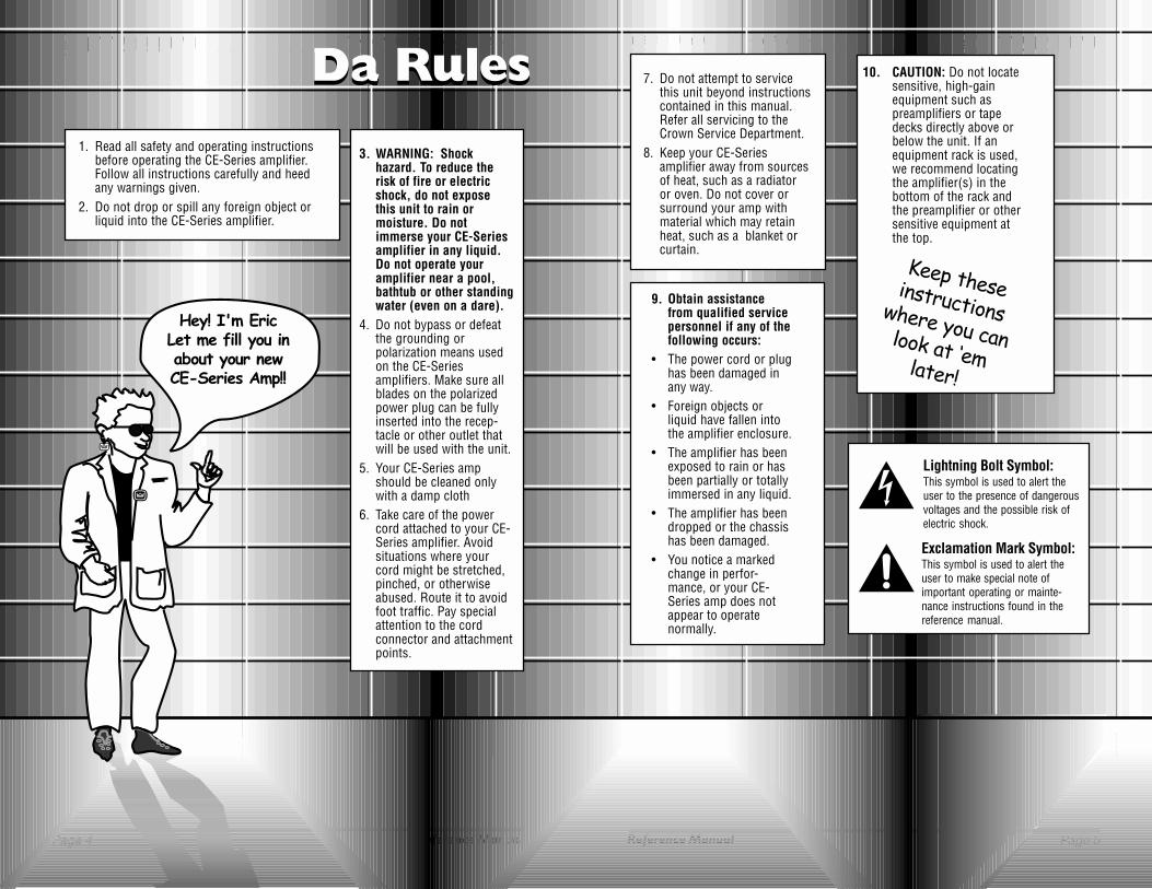
Hey! I'm EricLet me fill you inabout your newCE-Series Amp!!
3. WARNING: Shockhazard. To reduce therisk of fire or electricshock, do not exposethis unit to rain ormoisture. Do notimmerse your CE-Seriesamplifier in any liquid.Do not operate youramplifier near a pool,bathtub or other standingwater (even on a dare).
4. Do not bypass or defeatthe grounding orpolarization means usedon the CE-Seriesamplifiers. Make sure allblades on the polarizedpower plug can be fullyinserted into the recep-tacle or other outlet thatwill be used with the unit.
5. Your CE-Series ampshould be cleaned onlywith a damp cloth
6. Take care of the powercord attached to your CE-Series amplifier. Avoidsituations where yourcord might be stretched,pinched, or otherwiseabused. Route it to avoidfoot traffic. Pay specialattention to the cordconnector and attachmentpoints.
7. Do not attempt to servicethis unit beyond instructionscontained in this manual.Refer all servicing to theCrown Service Department.
8. Keep your CE-Seriesamplifier away from sourcesof heat, such as a radiatoror oven. Do not cover orsurround your amp withmaterial which may retainheat, such as a blanket orcurtain.
9. Obtain assistancefrom qualified servicepersonnel if any of thefollowing occurs:
• The power cord or plughas been damaged inany way.
• Foreign objects orliquid have fallen intothe amplifier enclosure.
• The amplifier has beenexposed to rain or hasbeen partially or totallyimmersed in any liquid.
• The amplifier has beendropped or the chassishas been damaged.
• You notice a markedchange in perfor-mance, or your CE-Series amp does notappear to operatenormally.
Lightning Bolt Symbol:This symbol is used to alert theuser to the presence of dangerousvoltages and the possible risk ofelectric shock.
Exclamation Mark Symbol:This symbol is used to alert theuser to make special note ofimportant operating or mainte-nance instructions found in thereference manual.
1. Read all safety and operating instructionsbefore operating the CE-Series amplifier.Follow all instructions carefully and heedany warnings given.
2. Do not drop or spill any foreign object orliquid into the CE-Series amplifier.
Keep theseinstructionswhere you canlook at �emlater!
10. CAUTION: Do not locatesensitive, high-gainequipment such aspreamplifiers or tapedecks directly above orbelow the unit. If anequipment rack is used,we recommend locatingthe amplifier(s) in thebottom of the rack andthe preamplifier or othersensitive equipment atthe top.
Page 7
CE-Series Amps with an Attitude!
Page 6
CE-Series Amps with an Attitude!
Reference Manual Reference Manual
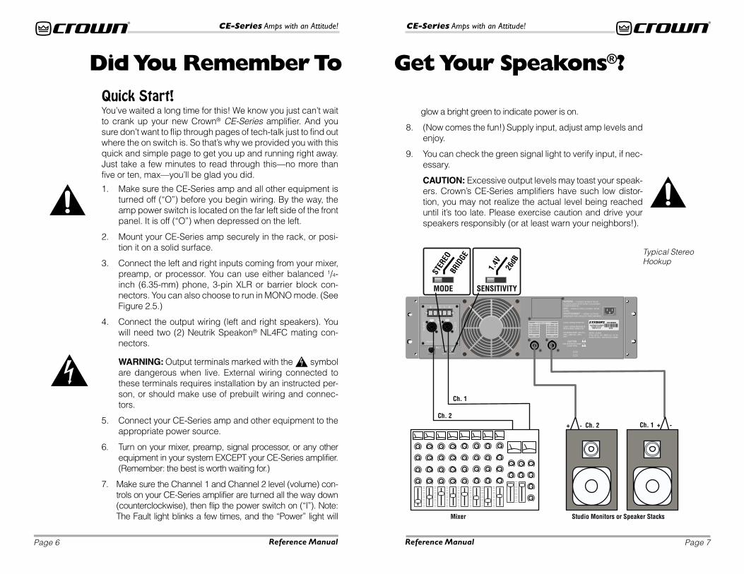
glow a bright green to indicate power is on.
8. (Now comes the fun!) Supply input, adjust amp levels andenjoy.
9. You can check the green signal light to verify input, if nec-essary.
CAUTION: Excessive output levels may toast your speak-ers. Crown’s CE-Series amplifiers have such low distor-tion, you may not realize the actual level being reacheduntil it’s too late. Please exercise caution and drive yourspeakers responsibly (or at least warn your neighbors!).
Quick Start!You’ve waited a long time for this! We know you just can’t waitto crank up your new Crown® CE-Series amplifier. And yousure don’t want to flip through pages of tech-talk just to find outwhere the on switch is. So that’s why we provided you with thisquick and simple page to get you up and running right away.Just take a few minutes to read through this—no more thanfive or ten, max—you’ll be glad you did.
1. Make sure the CE-Series amp and all other equipment isturned off (“O”) before you begin wiring. By the way, theamp power switch is located on the far left side of the frontpanel. It is off (“O”) when depressed on the left.
2. Mount your CE-Series amp securely in the rack, or posi-tion it on a solid surface.
3. Connect the left and right inputs coming from your mixer,preamp, or processor. You can use either balanced 1/4-inch (6.35-mm) phone, 3-pin XLR or barrier block con-nectors. You can also choose to run in MONO mode. (SeeFigure 2.5.)
4. Connect the output wiring (left and right speakers). Youwill need two (2) Neutrik Speakon® NL4FC mating con-nectors.
WARNING: Output terminals marked with the symbolare dangerous when live. External wiring connected tothese terminals requires installation by an instructed per-son, or should make use of prebuilt wiring and connec-tors.
5. Connect your CE-Series amp and other equipment to theappropriate power source.
6. Turn on your mixer, preamp, signal processor, or any otherequipment in your system EXCEPT your CE-Series amplifier.(Remember: the best is worth waiting for.)
7. Make sure the Channel 1 and Channel 2 level (volume) con-trols on your CE-Series amplifier are turned all the way down(counterclockwise), then flip the power switch on (“I”). Note:The Fault light blinks a few times, and the “Power” light will
Did You Remember To Get Your Speakons®?
Typical StereoHookup
Page 9
CE-Series Amps with an Attitude!
Page 8
CE-Series Amps with an Attitude!
Reference Manual Reference Manual
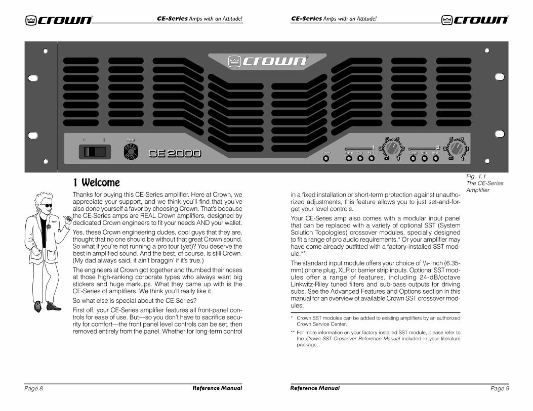
Fig. 1.1The CE-SeriesAmplifier
Thanks for buying this CE-Series amplifier. Here at Crown, weappreciate your support, and we think you’ll find that you’vealso done yourself a favor by choosing Crown. That’s becausethe CE-Series amps are REAL Crown amplifiers, designed bydedicated Crown engineers to fit your needs AND your wallet.Yes, these Crown engineering dudes, cool guys that they are,thought that no one should be without that great Crown sound.So what if you’re not running a pro tour (yet)? You deserve thebest in amplified sound. And the best, of course, is still Crown.(My dad always said, it ain’t braggin’ if it’s true.)
The engineers at Crown got together and thumbed their nosesat those high-ranking corporate types who always want bigstickers and huge markups. What they came up with is theCE-Series of amplifiers. We think you’ll really like it.
So what else is special about the CE-Series?First off, your CE-Series amplifier features all front-panel con-trols for ease of use. But—so you don’t have to sacrifice secu-rity for comfort—the front panel level controls can be set, thenremoved entirely from the panel. Whether for long-term control
1 Welcome
* Crown SST modules can be added to existing amplifiers by an authorizedCrown Service Center.
** For more information on your factory-installed SST module, please refer tothe Crown SST Crossover Reference Manual included in your literaturepackage.
in a fixed installation or short-term protection against unautho-rized adjustments, this feature allows you to just set-and-for-get your level controls.
Your CE-Series amp also comes with a modular input panelthat can be replaced with a variety of optional SST (SystemSolution Topologies) crossover modules, specially designedto fit a range of pro audio requirements.* Or your amplifier mayhave come already outfitted with a factory-installed SST mod-ule.**
The standard input module offers your choice of 1/4- inch (6.35-mm) phone plug, XLR or barrier strip inputs. Optional SST mod-ules offer a range of features, including 24-dB/octaveLinkwitz-Riley tuned filters and sub-bass outputs for drivingsubs. See the Advanced Features and Options section in thismanual for an overview of available Crown SST crossover mod-ules.
Page 11
CE-Series Amps with an Attitude!
Page 10
CE-Series Amps with an Attitude!
Reference Manual Reference Manual
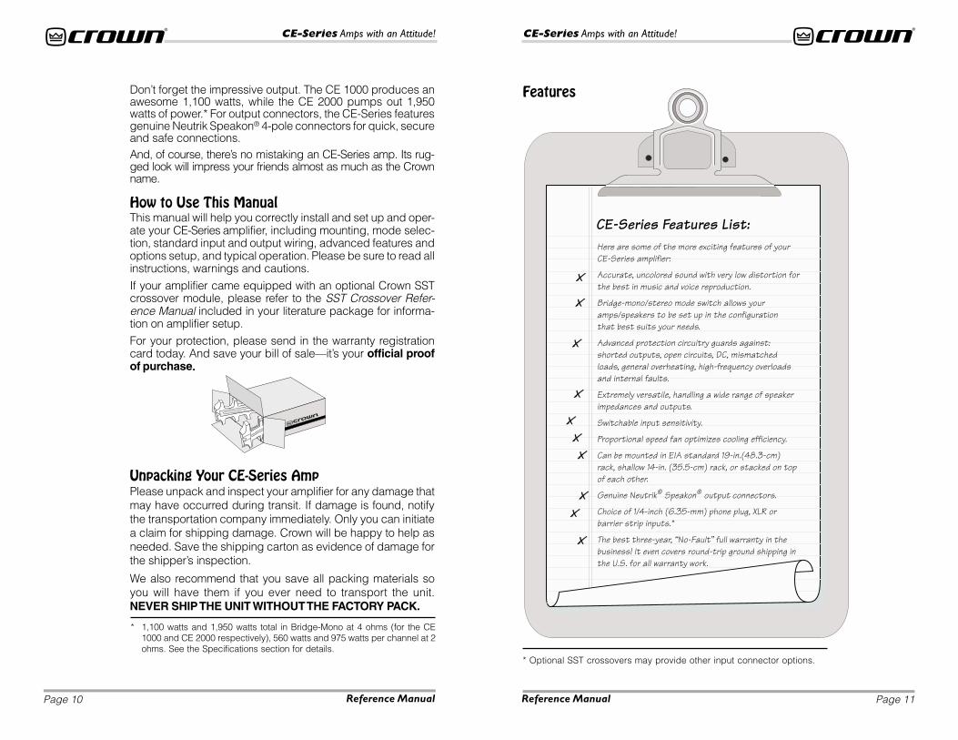
Features
* Optional SST crossovers may provide other input connector options.
Don’t forget the impressive output. The CE 1000 produces anawesome 1,100 watts, while the CE 2000 pumps out 1,950watts of power.* For output connectors, the CE-Series featuresgenuine Neutrik Speakon® 4-pole connectors for quick, secureand safe connections.And, of course, there’s no mistaking an CE-Series amp. Its rug-ged look will impress your friends almost as much as the Crownname.
How to Use This ManualThis manual will help you correctly install and set up and oper-ate your CE-Series amplifier, including mounting, mode selec-tion, standard input and output wiring, advanced features andoptions setup, and typical operation. Please be sure to read allinstructions, warnings and cautions.
If your amplifier came equipped with an optional Crown SSTcrossover module, please refer to the SST Crossover Refer-ence Manual included in your literature package for informa-tion on amplifier setup.
For your protection, please send in the warranty registrationcard today. And save your bill of sale—it’s your official proofof purchase.....
Unpacking Your CE-Series AmpPlease unpack and inspect your amplifier for any damage thatmay have occurred during transit. If damage is found, notifythe transportation company immediately. Only you can initiatea claim for shipping damage. Crown will be happy to help asneeded. Save the shipping carton as evidence of damage forthe shipper’s inspection.
We also recommend that you save all packing materials soyou will have them if you ever need to transport the unit.NEVER SHIP THE UNIT WITHOUT THE FACTORY PACK.
* 1,100 watts and 1,950 watts total in Bridge-Mono at 4 ohms (for the CE1000 and CE 2000 respectively), 560 watts and 975 watts per channel at 2ohms. See the Specifications section for details.
Page 13
CE-Series Amps with an Attitude!
Page 12
CE-Series Amps with an Attitude!
Reference Manual Reference Manual
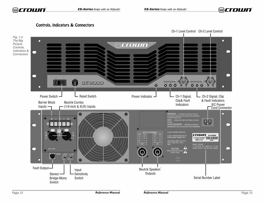
Fig. 1.2The BigPicture:Controls,Indicators &Connectors
Controls, Indicators & Connectors
Page 15
CE-Series Amps with an Attitude!
Page 14
CE-Series Amps with an Attitude!
Reference Manual Reference Manual
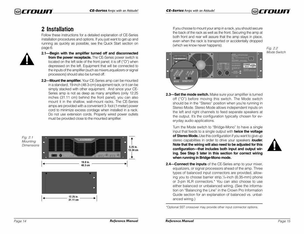
Fig. 2.1MountingDimensions
Fig. 2.2Mode Switch
2 InstallationFollow these instructions for a detailed explanation of CE-Seriesinstallation procedures and options. If you just want to get up andrunning as quickly as possible, see the Quick Start section onpage 6.
2.1—Begin with the amplifier turned off and disconnectedfrom the power receptacle. The CE-Series power switch islocated on the left side of the front panel; it is off (“O”) whendepressed on the left. Equipment that will be connected tothe inputs of the amplifier (such as mixers,equalizers or signalprocessors) should also be turned off.
2.2—Mount the amplifier. Your CE-Series amp can be mountedin a standard, 19-inch (48.3-cm) equipment rack, or it can besimply stacked with other equipment. And since your CE-Series amp is not as deep as many amplifiers (only 12.25inches (31.11 cm) behind the front panel), you can alsomount it in the shallow, wall-mount racks. The CE-Seriesamps are provided with a convenient 3- foot (1-meter) powercord to minimize excess cordage when installed in a rack.Do not use extension cords. Properly wired power outletsmust be provided close to the mounted amplifier.
If you choose to mount your amp in a rack, you should securethe back of the rack as well as the front. Securing the amp atboth front and rear will assure that the amp stays in place,even when the rack is transported or accidentally dropped(which we know never happens).
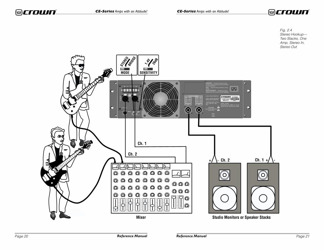
2.3—Set the mode switch. Make sure your amplifier is turnedoff (“O”) before moving this switch. The Mode switchshould be in the “Stereo” position when you’re running inStereo Mode. Stereo Mode allows independent inputs onthe left and right channels to feed separate speakers atthe output. It’s the configuration typically chosen for ev-eryday audio applications.
Turn the Mode switch to “Bridge-Mono” to have a singleinput that feeds to a single output with twice the voltageof Stereo Mode. Use this configuration if you want to give upstereo capabilities in order to drive your speakers louder.Note that the wiring will also need to be adjusted for thisconfiguration—that includes both input and output wir-ing. See Step 5 later in this section for correct wiringwhen running in Bridge-Mono mode.
2.4—Connect the inputs of the CE-Series amp to your mixer,equalizers, or signal processors ahead of the amp. Threetypes of balanced input connectors are provided, allow-ing you to choose barrier strip,1/4-inch (6.35-mm) phoneor 3-pin XLR connectors.* You can also choose to useeither balanced or unbalanced wiring. (See the informa-tion on “Balancing the Line” in the Crown Pro InformationGuide section for an explanation of balanced vs. unbal-anced wiring.)
*Optional SST crossover may provide other input connector options.
Page 17
CE-Series Amps with an Attitude!
Page 16
CE-Series Amps with an Attitude!
Reference Manual Reference Manual
Input Wiring Tips1. For all input connectivity, use shielded wire only. Cables with a foilwrap shield or a high-density braid are superior. Cables with astranded spiral shield, although very flexible, will break down overtime and cause noise problems.
2. Try to avoid using unbalanced lines with professional equipment. Ifyou have no choice, keep the cables as short as possible. (Refer to
the information on “Balancing the Line” in the Crown Pro Information Guide section.)
3. To minimize hum and crosstalk, avoid running low-level input, high-level output and ACpower feeds in the same path. Try to run differing signal paths at 90° to one another. If youmust use a common path for all cables, use a star-quad cable for the low-level signals.
4. When changing input connectors or wiring, turn the amplifier level controls all the waydown (counter-clockwise) before connecting or disconnecting input plugs.
5. When changing output connections, turn the amplifier level down and the AC power off tominimize the chance of short-circuiting the output.
* You can purchase the Speakon® NL4FC connectors from your local dealer,or contact NEUTRIK AG, Im alten riet 34, Schaan FL-9494, FurstentumLiechtenstein, 011-41-75-237-2424, FAX 011-41-75-232-5393,www.neutrik.com or Neutrik USA, Inc., 195 Lehigh Ave., Lakewood, NJ08701-4527, (908) 901-9488, Fax (908) 901-9608, www.neutrikusa.com orCrown Audio, Inc., 1718 West Mishawaka Road, Elkhart, IN 46517-4095,USA, 219-294-8000, FAX 219-294-8329, www.crownaudio.com.
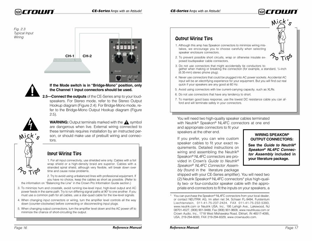
Fig. 2.3Typical InputWiring
If the Mode switch is in “Bridge-Mono” position, onlythe Channel 1 input connectors should be used.
2.5—Connect the outputs of the CE-Series amp to your loud-speakers. For Stereo mode, refer to the Stereo OutputHookup diagram (Figure 2.4). For Bridge-Mono mode, re-fer to the Bridge-Mono Output Hookup diagram (Figure2.5).
WARNING: Output terminals marked with the symbolare dangerous when live. External wiring connected tothese terminals requires installation by an instructed per-son, or should make use of prebuilt wiring and connec-tors.
You will need two high-quality speaker cables terminatedwith Neutrik® Speakon® NL4FC connectors at one endand appropriate connectors to fit yourspeakers at the other end.
If you prefer, you can wire customspeaker cables to fit your exact re-quirements. Detailed instructions onwiring and assembling the Neutrik®
Speakon® NL4FC connectors are pro-vided in Crown’s Guide to Neutrik®
Speakon® NL4FC Connector Assem-bly (found in the literature packageshipped with your CE-Series amplifier). You will need two(2) Neutrik Speakon® NL4FC connectors* plus high-qual-ity two- or four-conductor speaker cable with the appro-priate end-connectors to fit the inputs on your speakers, a
Output Wiring Tips1. Although this amp has Speakon connectors to minimize wiring mis-
takes, we encourage you to choose carefully when selectingspeaker enclosure connectors.
2. To prevent possible short circuits, wrap or otherwise insulate ex-posed loudspeaker cable connectors.
3. Do not use connectors that might accidentally tie conductors to-gether when making or breaking the connection (for example, a standard, 1/4-inch(6.35-mm) stereo phone plug).
4. Never use connectors that could be plugged into AC power sockets. Accidental ACinput will be an electrifying experience for your equipment. But you will find out realquick if your speakers are any good at 60 Hz.
5. Avoid using connectors with low current-carrying capacity, such as XLRs.
6. Do not use connectors that have any tendency to short.
7. To maintain good bass response, use the lowest DC resistance cable you can af-ford and will terminate safely in your connectors.
MODE SENSITIVITY
STER
EO
1.4
V
BR
IDG
E
26dB
WIRING SPEAKON®
OUTPUT CONNECTORS:
See the Guide to Neutrik®
Speakon® NL4FC Connec-tor Assembly included inyour literature package.
Page 19
CE-Series Amps with an Attitude!
Page 18
CE-Series Amps with an Attitude!
Reference Manual Reference Manual
Why Speakon?For amplifiers, the most popular termination device on profes-sional products has been the dual banana (which incidentally waspioneered by Crown with the DC300 model). However, recentregulatory requirements in Europe have outlawed the use of thedual banana plug and forced users to terminate speaker cableswith spade lugs or bare ends—an approach that is clearly not
advantageous to the customer who wants to reconfigure his system or quickly changeout a defective product. It is possible that similar regulatory controls will appear world-wide over the next few years.
One solution to this problem is to use the Neutrik Speakon® connector. Here at Crown,we wanted to develop a system for you that eliminated the need for specialized, time-consuming, interface cables. The major loudspeaker manufacturers have been usingSpeakon connectors for the input termination on their products for several years now,so you can be assured of the connector’s reliability in the workplace. With Speakonconnectors, you can plug straight from the amp to the speaker, and start making thosegreat sounds right away.
The Speakon connector used on this amplifier meets all known safety regulations.Once wired correctly, the connector cannot be plugged in backwards, causing thetype of inverted polarity situations that are common with banana hookups. It will pro-vide a safe, secure and reliable method of interfacing your amplifier to the load.
pair of needle-nosed pliers and a 1/16-inch Allen wrench ora flat blade screw driver to assemble the Speakon® con-nectors.
2.6—Check to make sure that adequate ventilation hasbeen provided. Even though this amplifier has some ofthe most efficient heat sinks in the marketplace, it must beable to breathe. So make sure that the front vents arenever blocked and that the exhaust fan (out the back) isnot blocked or covered by cables.
An amplifier running at high sound pressure levels intolow-impedance loads, will typically put out lots of hot air,so make sure it can go somewhere.
If you are running your equipment in dusty or dirty environ-ments, it is advisable to pre-filter the air using industrialfurnace filters. These filters can be taped or fastened to thefront of the equipment rack, ensuring a clean air supplythrough a large surface area that will require minimummaintenance.
2.7—Check once more to make sure the amplifier hasbeen set up correctly. Then follow the steps in the Opera-tion section to operate the amplifier.
Cooling TipsIf you allow spaces between pieces of equipment in your rack,make sure you block the front with blank, solid (not perforated) pan-els. This will allow the rack to act as a chimney with hot air exhaust-ing at the top, not recirculating between adjacent amplifiers.
Page 21
CE-Series Amps with an Attitude!
Page 20
CE-Series Amps with an Attitude!
Reference Manual Reference Manual
Fig. 2.4Stereo Hookup—Two Stacks, OneAmp, Stereo In,Stereo Out

Page 23
CE-Series Amps with an Attitude!
Page 22
CE-Series Amps with an Attitude!
Reference Manual Reference Manual
Fig. 2.5Bridge-MonoOutput Hookup—Great for Subs...orWhen You Want ItWAY LOUD!
Page 25
CE-Series Amps with an Attitude!
Page 24
CE-Series Amps with an Attitude!
Reference Manual Reference Manual
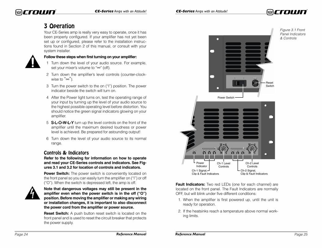
3 OperationYour CE-Series amp is really very easy to operate, once it hasbeen properly configured. If your amplifier has not yet beenset up or configured, please refer to the installation instruc-tions found in Section 2 of this manual, or consult with yoursystem installer.
Follow these steps when first turning on your amplifier:
1 Turn down the level of your audio source. For example,set your mixer’s volume to “∞” (off).
2 Turn down the amplifier’s level controls (counter-clock-wise to “∞”).
3 Turn the power switch to the on (“I”) position. The powerindicator beside the switch will turn on.
4 After the Power light turns on, test the operating range ofyour input by turning up the level of your audio source tothe highest possible operating level before distortion. Youshould notice the green signal indicators glowing on youramplifier.
5 S-L-O-W-L-YS-L-O-W-L-YS-L-O-W-L-YS-L-O-W-L-YS-L-O-W-L-Y turn up the level controls on the front of theamplifier until the maximum desired loudness or powerlevel is achieved. Be prepared for astounding output!
6 Turn down the level of your audio source to its normalrange.
Controls & IndicatorsRefer to the following for information on how to operateand read your CE-Series controls and indicators. See Fig-ures 3.1 and 3.2 for location of controls and indicators.
Power Switch: The power switch is conveniently located onthe front panel so you can easily turn the amplifier on (“I”) or off(“O”). When the switch is depressed left, the amp is off.
Note that dangerous voltages may still be present in theamplifier even when the power switch is in the off (“O”)position. Before moving the amplifier or making any wiringor installation changes, it is important to also disconnectthe power cord from the amplifier or power source.
Reset Switch: A push button reset switch is located on thefront panel and is used to reset the circuit breaker that protectsthe power supply.
Figure 3.1 FrontPanel Indicators& Controls
Fault Indicators: Two red LEDs (one for each channel) arelocated on the front panel. The Fault Indicators are normallyOFF, but will blink under five different conditions:
1. When the amplifier is first powered up, until the unit isready for operation.
2. If the heatsinks reach a temperature above normal work-ing limits.
Page 27
CE-Series Amps with an Attitude!
Page 26
CE-Series Amps with an Attitude!
Reference Manual Reference Manual
3. If the transformer thermal protection circuit is activated.
4. If amplifier output wires develop a short-circuit.
5. Should the amplifier output stage become non-operational.
The fault status of the amplifier can also be monitored remotelyby attaching a signalling device to the Fault jack located onthe amplifier back-panel. See the Advanced Features andOptions section of this manual for more information on faultmonitoring and suggestions for signalling device circuity.
Some fault conditions may cause the output of the amplifier tobe muted.
Clip Indicator: Two red LEDs (one for each channel) are lo-cated on the front panel. The Clip indicators turn on when dis-tortion is audible in the amplifier output.
Signal Indicator: Two green LEDs (one for each channel) arelocated on the front panel. Unlike some of our other amplifiers,the Signal indicators on the CE-Series amplifier lluminate whena signal (> –40 dBm) is present at the INPUT of the amplifierfor that channel. Because these indicators receive the signalbefore the level controls, they can be used to troubleshoot wir-ing problems within a system. If the Signal indicator for a chan-nel is not lit, no signal is reaching the amplifier on that channel.
Power Indicator: A green LED is located on the front panel.The Power indicator lights when your CE-Series amp has beenturned on and has power.
Level Controls: Two rotary level controls (one for each chan-nel) are located on the front panel. Use these controls to adjusteach channel’s output. To decrease the level, rotate the controlcounter-clockwise (to “∞”). To increase the level, rotate it clock-wise (to “0”).
If you wish, the level control knobs may be pulled from the frontpanel and the holes plugged with the supplied caps to mini-mize tampering of control settings.
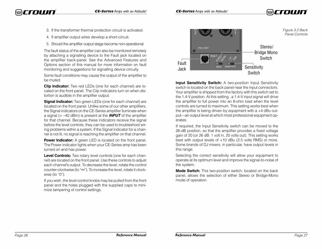
Input Sensitivity Switch: A two-position Input Sensitivityswitch is located on the back panel near the input connectors.Your amplifier is shipped from the factory with this switch set tothe 1.4-V position. At this setting , a 1.4-V input signal will drivethe amplifier to full power into an 8-ohm load when the levelcontrols are turned to maximum. This setting works best whenthe amplifier is being driven by equipment with a +4 dBu out-put—an output level at which most professional equipment op-erates.
If required, the Input Sensitivity switch can be moved to the26-dB position, so that the amplifier provides a fixed voltagegain of 20 (or 26 dB: 1 volt in, 20 volts out). This setting worksbest with output levels of +10 dBu (2.5 volts RMS) or more.Some brands of DJ mixers, in particular, have output levels inthis range.
Selecting the correct sensitivity will allow your equipment tooperate at its optimum level and improve the signal-to-noise ofthe system.
Mode Switch: This two-position switch, located on the backpanel, allows the selection of either Stereo or Bridge-Monomode of operation.
Figure 3.2 BackPanel Controls
Page 29
CE-Series Amps with an Attitude!
Page 28
CE-Series Amps with an Attitude!
Reference Manual Reference Manual
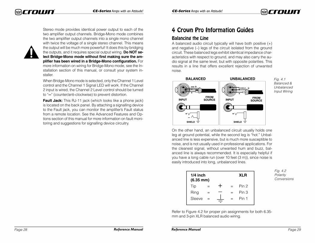
On the other hand, an unbalanced circuit usually holds oneleg at ground potential, while the second leg is “hot.” Unbal-anced line is less expensive, but is much more susceptible tonoise, and is not usually used in professional applications. Forthe cleanest signal, without unwanted hum and buzz, bal-anced line is always recommended. It is especially helpful ifyou have a long cable run (over 10 feet (3 m)), since noise iseasily introduced into long, unbalanced lines.
–+
3
1
2
GND
FROMSOURCEINPUT
BALANCED
+–
SHIELD
FROMSOURCEINPUT
UNBALANCED
+
SHIELD
+3
1
2
SHIELD
4 Crown Pro Information GuidesBalancing the LineA balanced audio circuit typically will have both positive (+)and negative (–) legs of the circuit isolated from the groundcircuit. These balanced legs exhibit identical impedance char-acteristics with respect to ground, and may also carry the au-dio signal at the same level, but with opposite polarities. Thisresults in a line that offers excellent rejection of unwantednoise.
Fig. 4.1Balanced &UnbalancedInput Wiring
Fig. 4.2PolarityConversions
Stereo mode provides identical power output to each of thetwo amplifier output channels. Bridge-Mono mode combinesthe two amplifier output channels into a single mono channelwith twice the voltage of a single stereo channel. This meansthe output will be much more powerful! It does this by bridgingthe outputs, and it requires special output wiring. Do NOT se-lect Bridge-Mono mode without first making sure the am-plifier has been wired in a Bridge-Mono configuration. Formore information on wiring for Bridge-Mono mode, see the In-stallation section of this manual, or consult your system in-staller.
When Bridge-Mono mode is selected, only the Channel 1 Levelcontrol and the Channel 1 Signal LED will work. If the Channel2 input is wired, the Channel 2 Level control should be turnedto “∞” (counter/anti-clockwise) to prevent distortion.
Fault Jack: This RJ-11 jack (which looks like a phone jack)is located on the back panel. By attaching a signalling deviceto the Fault jack, you can monitor the amplifier’s Fault statusfrom a remote location. See the Advanced Features and Op-tions section of this manual for more information on fault moni-toring and suggestions for signalling device circuitry.
1/4 inch XLR(6.35 mm)
Tip = + = Pin 2
Ring = – = Pin 3
Sleeve = = Pin 1
Refer to Figure 4.2 for proper pin assignments for both 6.35-mm and 3-pin XLR balanced audio wiring.
Page 31
CE-Series Amps with an Attitude!
Page 30
CE-Series Amps with an Attitude!
Reference Manual Reference Manual
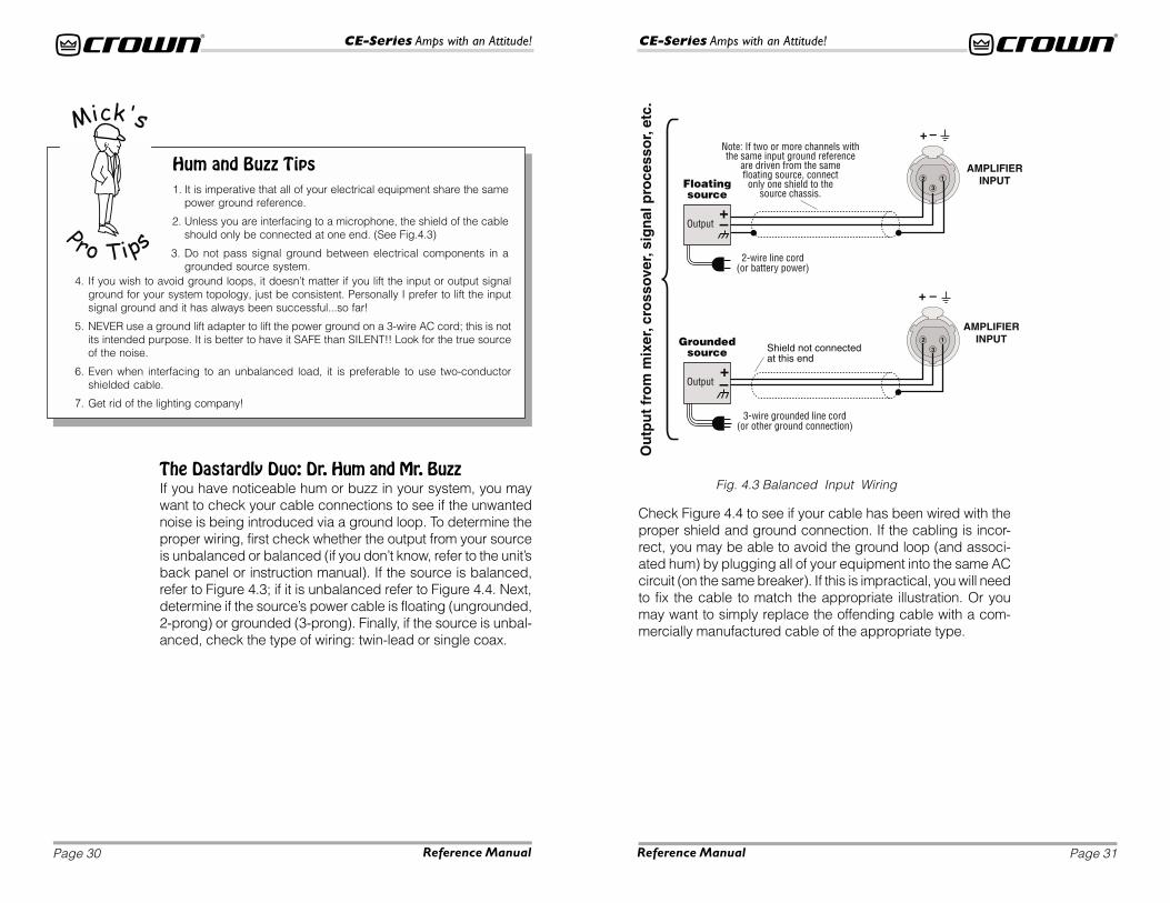
Hum and Buzz Tips1. It is imperative that all of your electrical equipment share the same
power ground reference.
2. Unless you are interfacing to a microphone, the shield of the cableshould only be connected at one end. (See Fig.4.3)
3. Do not pass signal ground between electrical components in agrounded source system.
4. If you wish to avoid ground loops, it doesn’t matter if you lift the input or output signalground for your system topology, just be consistent. Personally I prefer to lift the inputsignal ground and it has always been successful...so far!
5. NEVER use a ground lift adapter to lift the power ground on a 3-wire AC cord; this is notits intended purpose. It is better to have it SAFE than SILENT!! Look for the true sourceof the noise.
6. Even when interfacing to an unbalanced load, it is preferable to use two-conductorshielded cable.
7. Get rid of the lighting company!
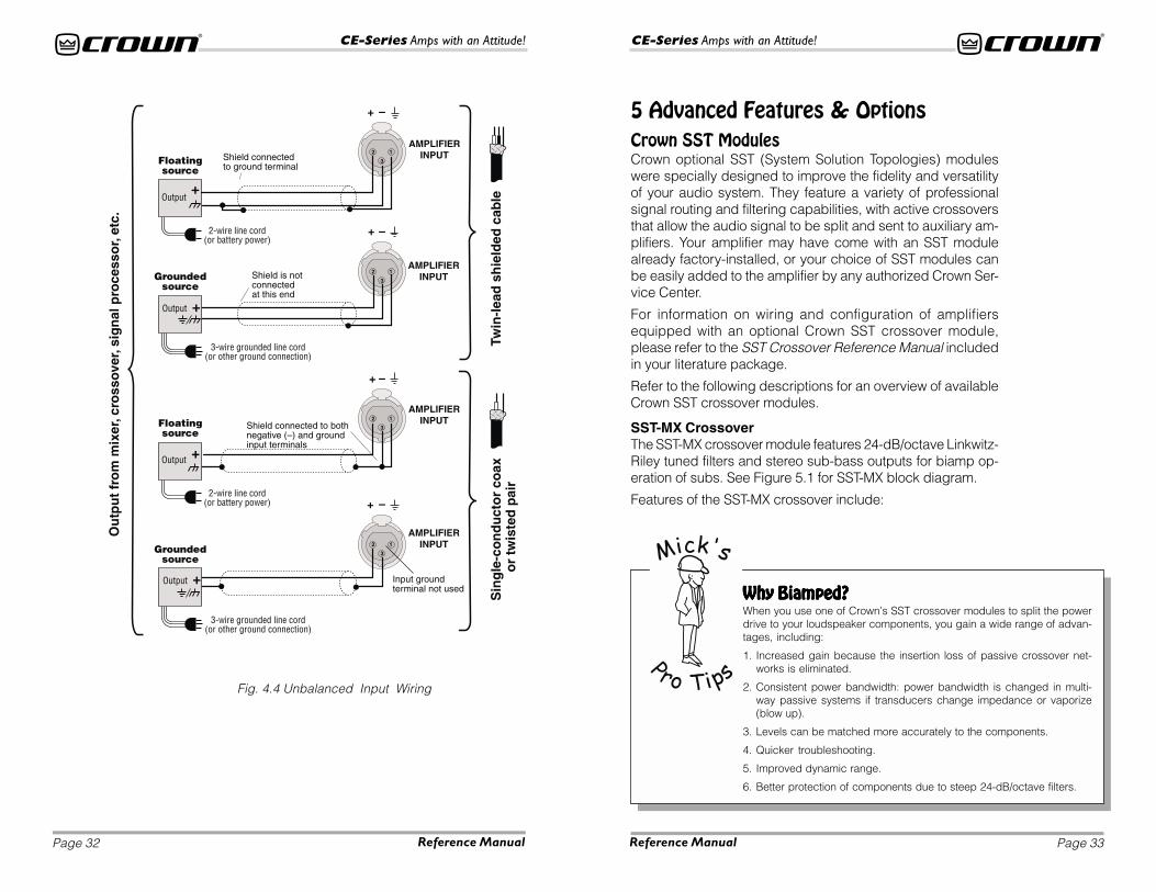
Fig. 4.3 Balanced Input WiringThe Dastardly Duo: Dr. Hum and Mr. BuzzIf you have noticeable hum or buzz in your system, you maywant to check your cable connections to see if the unwantednoise is being introduced via a ground loop. To determine theproper wiring, first check whether the output from your sourceis unbalanced or balanced (if you don’t know, refer to the unit’sback panel or instruction manual). If the source is balanced,refer to Figure 4.3; if it is unbalanced refer to Figure 4.4. Next,determine if the source’s power cable is floating (ungrounded,2-prong) or grounded (3-prong). Finally, if the source is unbal-anced, check the type of wiring: twin-lead or single coax.
Check Figure 4.4 to see if your cable has been wired with theproper shield and ground connection. If the cabling is incor-rect, you may be able to avoid the ground loop (and associ-ated hum) by plugging all of your equipment into the same ACcircuit (on the same breaker). If this is impractical, you will needto fix the cable to match the appropriate illustration. Or youmay want to simply replace the offending cable with a com-mercially manufactured cable of the appropriate type.
Page 33
CE-Series Amps with an Attitude!
Page 32
CE-Series Amps with an Attitude!
Reference Manual Reference Manual
5 Advanced Features & OptionsCrown SST ModulesCrown optional SST (System Solution Topologies) moduleswere specially designed to improve the fidelity and versatilityof your audio system. They feature a variety of professionalsignal routing and filtering capabilities, with active crossoversthat allow the audio signal to be split and sent to auxiliary am-plifiers. Your amplifier may have come with an SST modulealready factory-installed, or your choice of SST modules canbe easily added to the amplifier by any authorized Crown Ser-vice Center.
For information on wiring and configuration of amplifiersequipped with an optional Crown SST crossover module,please refer to the SST Crossover Reference Manual includedin your literature package.
Refer to the following descriptions for an overview of availableCrown SST crossover modules.
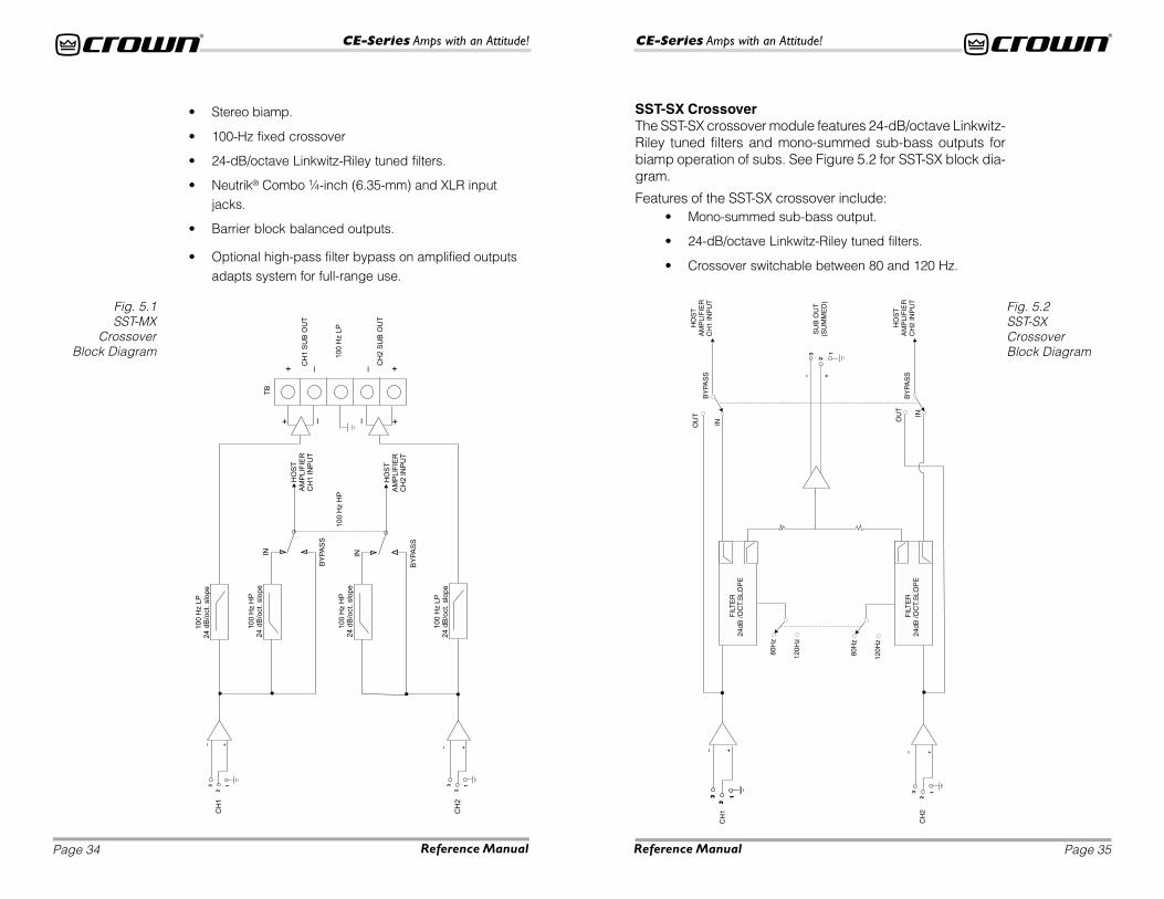
SST-MX CrossoverThe SST-MX crossover module features 24-dB/octave Linkwitz-Riley tuned filters and stereo sub-bass outputs for biamp op-eration of subs. See Figure 5.1 for SST-MX block diagram.
Features of the SST-MX crossover include:
Why Biamped?Why Biamped?Why Biamped?Why Biamped?Why Biamped?When you use one of Crown’s SST crossover modules to split the powerdrive to your loudspeaker components, you gain a wide range of advan-tages, including:
1. Increased gain because the insertion loss of passive crossover net-works is eliminated.
2. Consistent power bandwidth: power bandwidth is changed in multi-way passive systems if transducers change impedance or vaporize(blow up).
3. Levels can be matched more accurately to the components.
4. Quicker troubleshooting.
5. Improved dynamic range.
6. Better protection of components due to steep 24-dB/octave filters.
Fig. 4.4 Unbalanced Input Wiring
Page 35
CE-Series Amps with an Attitude!
Page 34
CE-Series Amps with an Attitude!
Reference Manual Reference Manual
Fig. 5.1SST-MX
CrossoverBlock Diagram
CH
1
CH
1S
UB
OU
T
TB
CH
2S
UB
OU
T
100
Hz
LP
CH
2
–– ++
IN
BY
PA
SS
100
Hz
HP
HO
ST
AM
PLIF
IER
CH
1IN
PU
T
HO
ST
AM
PLIF
IER
CH
2IN
PU
T
100
Hz
LP
24
dB
/oct.
slo
pe
100
Hz
HP
24
dB
/oct.
slo
pe
IN
BY
PA
SS
100
Hz
LP
24
dB
/oct.
slo
pe
100
Hz
HP
24
dB
/oct.
slo
pe
–+ – +
– +
3
2
1
– +
3
2
1
Fig. 5.2SST-SXCrossoverBlock Diagram
• Stereo biamp.
• 100-Hz fixed crossover
• 24-dB/octave Linkwitz-Riley tuned filters.
• Neutrik® Combo ¼-inch (6.35-mm) and XLR inputjacks.
• Barrier block balanced outputs.
• Optional high-pass filter bypass on amplified outputsadapts system for full-range use.
SST-SX CrossoverThe SST-SX crossover module features 24-dB/octave Linkwitz-Riley tuned filters and mono-summed sub-bass outputs forbiamp operation of subs. See Figure 5.2 for SST-SX block dia-gram.
Features of the SST-SX crossover include:• Mono-summed sub-bass output.
• 24-dB/octave Linkwitz-Riley tuned filters.
• Crossover switchable between 80 and 120 Hz.
Page 37
CE-Series Amps with an Attitude!
Page 36
CE-Series Amps with an Attitude!
Reference Manual Reference Manual
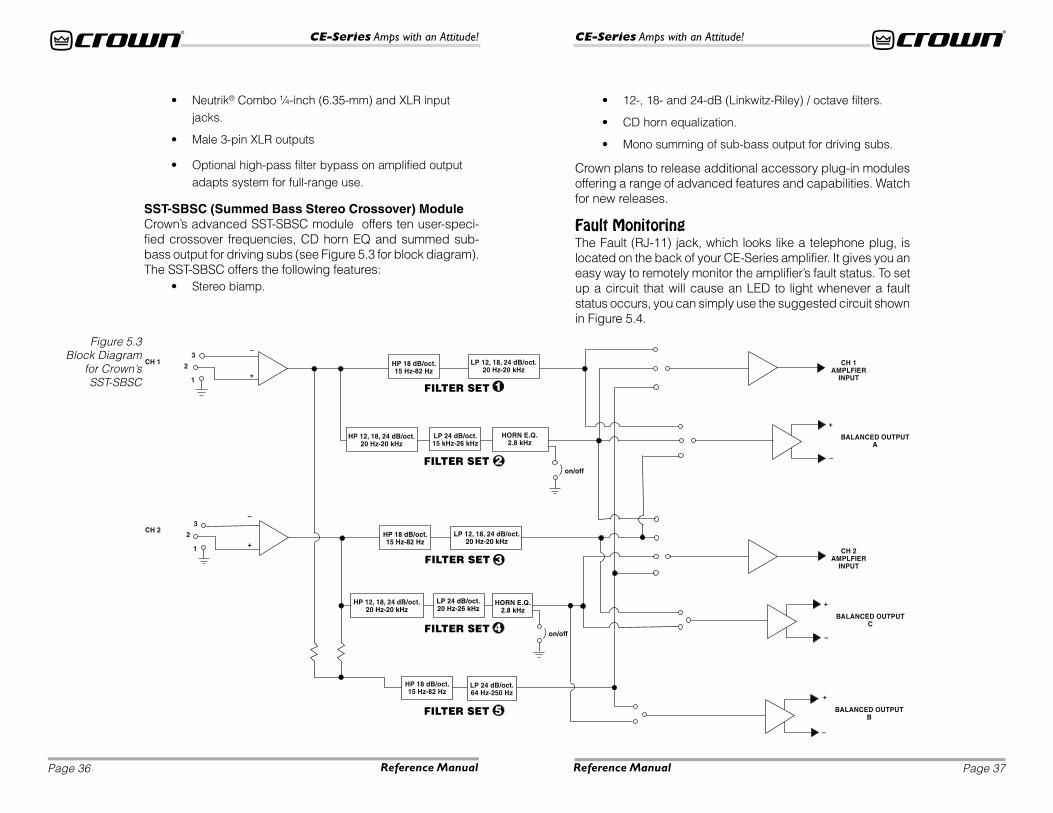
Figure 5.3Block Diagram
for Crown’sSST-SBSC
• Neutrik® Combo ¼-inch (6.35-mm) and XLR inputjacks.
• Male 3-pin XLR outputs
• Optional high-pass filter bypass on amplified outputadapts system for full-range use.
SST-SBSC (Summed Bass Stereo Crossover) ModuleCrown’s advanced SST-SBSC module offers ten user-speci-fied crossover frequencies, CD horn EQ and summed sub-bass output for driving subs (see Figure 5.3 for block diagram).The SST-SBSC offers the following features:
• Stereo biamp.
• 12-, 18- and 24-dB (Linkwitz-Riley) / octave filters.
• CD horn equalization.
• Mono summing of sub-bass output for driving subs.
Crown plans to release additional accessory plug-in modulesoffering a range of advanced features and capabilities. Watchfor new releases.
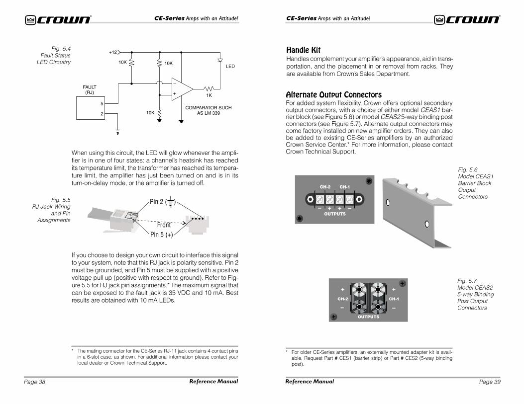
Fault MonitoringThe Fault (RJ-11) jack, which looks like a telephone plug, islocated on the back of your CE-Series amplifier. It gives you aneasy way to remotely monitor the amplifier’s fault status. To setup a circuit that will cause an LED to light whenever a faultstatus occurs, you can simply use the suggested circuit shownin Figure 5.4.
Page 39
CE-Series Amps with an Attitude!
Page 38
CE-Series Amps with an Attitude!
Reference Manual Reference Manual
When using this circuit, the LED will glow whenever the ampli-fier is in one of four states: a channel’s heatsink has reachedits temperature limit, the transformer has reached its tempera-ture limit, the amplifier has just been turned on and is in itsturn-on-delay mode, or the amplifier is turned off.
Fig. 5.5RJ Jack Wiring
and PinAssignments
Handle KitHandles complement your amplifier’s appearance, aid in trans-portation, and the placement in or removal from racks. Theyare available from Crown’s Sales Department.
Fig. 5.6Model CEAS1Barrier BlockOutputConnectors
If you choose to design your own circuit to interface this signalto your system, note that this RJ jack is polarity sensitive. Pin 2must be grounded, and Pin 5 must be supplied with a positivevoltage pull up (positive with respect to ground). Refer to Fig-ure 5.5 for RJ jack pin assignments.* The maximum signal thatcan be exposed to the fault jack is 35 VDC and 10 mA. Bestresults are obtained with 10 mA LEDs.
Alternate Output ConnectorsFor added system flexibility, Crown offers optional secondaryoutput connectors, with a choice of either model CEAS1 bar-rier block (see Figure 5.6) or model CEAS2 5-way binding postconnectors (see Figure 5.7). Alternate output connectors maycome factory installed on new amplifier orders. They can alsobe added to existing CE-Series amplifiers by an authorizedCrown Service Center.* For more information, please contactCrown Technical Support.
* For older CE-Series amplifiers, an externally mounted adapter kit is avail-able. Request Part # CES1 (barrier strip) or Part # CES2 (5-way bindingpost).
Fig. 5.7Model CEAS25-way BindingPost OutputConnectors
* The mating connector for the CE-Series RJ-11 jack contains 4 contact pinsin a 6-slot case, as shown. For additional information please contact yourlocal dealer or Crown Technical Support.
Fig. 5.4Fault Status
LED Circuitry
Page 41
CE-Series Amps with an Attitude!
Page 40
CE-Series Amps with an Attitude!
Reference Manual Reference Manual
Fig. 5.8Tamper-Resistant
Hole Plugs Installedin a CE-Series
Amplifier
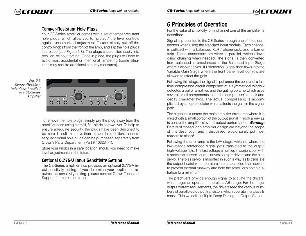
To remove the hole plugs, simply pry the plug away from theamplifier case using a small, flat-blade screwdriver. To help toensure adequate security, the plugs have been designed tobe more difficult to remove than to place into position. If neces-sary, additional hole plugs can be purchased separately fromCrown’s Parts Department (Part # 103234-1).
Store your knobs in a safe location should you need to makelevel adjustments in the future.
Optional 0.775-V Input Sensitivity SettingThe CE-Series amplifier also provides an optional 0.775-V in-put sensitivity setting. If you determine your application re-quires this sensitivity setting, please contact Crown TechnicalSupport for more information.
6 Principles of OperationFor the sake of simplicity, only channel one of the amplifier isdescribed.
Signal is presented to the CE-Series through one of three con-nectors when using the standard input module. Each channelis outfitted with a balanced XLR / phone jack, and a barrierstrip. These connectors are wired in parallel, which allowsdaisy chaining when needed. The signal is then convertedfrom balanced to unbalanced in the Balanced Input Stagewhere it also receives RFI protection. Signal then flows into theVariable Gain Stage where the front panel level controls areallowed to affect the gain.
Following this stage, the signal is put under the control of a full-time compressor circuit comprised of a symmetrical windowdetector, a buffer amplifier, and the gating op amp which usesseveral small components to set the compressor’s attack anddecay characteristics. The actual compressing is accom-plished by an opto-isolator which affects the gain in the signalpath.
The signal next enters the main amplifier error amp where it ismixed with a small portion of the output signal in such a way asto control the amplifier’s overall output performance. Warning:Details of closed loop amplifier design are beyond the scopeof this description and if discussed, would surely put mostreaders to sleep!
Following the error amp is the LVA stage, which is where thelow-voltage referenced signal gets translated to the outputhigh-voltage rails. The last voltage amplifier, in conjunction witha bootstrap current source, drives both predrivers and the biasservo. The bias servo is mounted in such a way as to translatethe output heatsink temperature into a controlled bias currentto prevent thermal runaway and hold the amplifier’s notch dis-tortion to a minimum.
The predrivers provide enough signal to activate the drivers,which together operate in the class AB range. For the majoroutput current requirements, the drivers feed the various num-bers of paralleled output transistors which operate in a class Bmode. This we call the Triple-Deep Darlington Output Stages.
Tamper-Resistant Hole PlugsYour CE-Series amplifier comes with a set of tamper-resistanthole plugs, which allow you to “protect” the level controlsagainst unauthorized adjustment. To use, simply pull off thecontrol knobs from the front of the amp, and slip the hole plugsinto place (see Figure 5.8). The plugs should slide easily intoposition, without forcing. Once in place, the plugs will help toavoid most accidental or intentional tampering (some situa-tions may require additional security measures).

Page 43
CE-Series Amps with an Attitude!
Page 42
CE-Series Amps with an Attitude!
Reference Manual Reference Manual
The turn on delay circuit functions to keep the output relayopen until all the voltages are up and stable, both in the ampli-fier, and in all the components in the system ahead of the am-plifier.
Heatsink temperature is monitored by a thermal probe at-tached to the heatsink. As the temperature rises, the probesends a proportional current to the proportional speed fan cir-cuit which starts the fan. Should the power transformer reachits maximum safe temperature, an internal thermal switchopens and the fan circuit turns on full speed to quickly cooldown the amplifier. It also disconnects the load via the outputrelay, removing any output current and further speeding a cool-down cycle. Extra care was taken during the design stage toset this point both to protect your investment and to guardagainst nuisance tripping.
Whenever the heatsinks or the transformer reach a maximumtemperature, or during the normal turn on delay window, thefront panel Fault LEDs will blink to get your attention.
TRANSLATOR LVA
BIAS
CURRENTSOURCE
BALANCEINPUT STAGE
VARIABLEGAIN STAGE
ERRORAMP
BALANCEDINPUTS
TO SIGNALPRESENCEINDICATOR
COMPRESSORCONTROL
TO CLIPINDICATOR
BUFFER
MUTE
DC PROTECTLOGIC
TOFAULT
CONNECTOR
–VCC –VCC
+ HI-VOLTAGEBOOTSTRAP
BIASBIASBIASBIASBIASTDVI
LIMITER
TRIPLE-DEEPDARLINGTONNPN POSITIVE
OUTPUT STAGE
TRIPLE-DEEPDARLINGTON
NPN NEGATIVEOUTPUT STAGE
PROPORTIONALSPEED
FANCONTROL
FAN
DCPROTECT
HEATSINKTEMPERATURE
OUTPUTCONTROL
HEATSINKTEMPERATURE
TRANSFORMERTEMPERATURE
TO FAULTINDICATOR
POWER
SUPPLY
+ VCC+ 15V
– 15V– VCC
TURN-ONDELAY
+
OUTPUT
BOOTSTRAPCIRCUIT
+ HI-VOLTAGE BOOTSTRAP
The output transistors are protected by the Time DependentVoltage & Current circuit. This circuit protects the devices fromextending beyond their safe area of operation, but allows thedevices to provide high bursts of peak power with music, al-lowing your amplifier to deliver more punch. When all is saidand done, this amplifier output topology offers a good combi-nation of low quiescent amplifier heating, great distortion per-formance at high powers, and relative simplicity, withimpressive reliability and value.
All output power is delivered through 4-circuit Speakon® con-nectors. These connectors have been wired in such a way asto allow you the most versatility. The Channel 1 and 2 connec-tors are cross wired so you can cover all options, from dualcable stereo (typical), to Bridge-Mono in one connector, to run-ning a bi-amp speaker with one amplifier and one cable perspeaker cabinet!
The output relay, in conjunction with input signal mute circuit,assures the amplifier will be well-behaved during turn on andoff. In the event of an amplifier output failure, a triac will acti-vate to turn off the offending channel and protect your speak-ers.
Fig. 6.1CE-Series
Amplifier BlockDiagram
(Shown withStandard Input
Module)
Page 45
CE-Series Amps with an Attitude!
Page 44
CE-Series Amps with an Attitude!
Reference Manual Reference Manual
A modular jack is mounted on the back panel (same type asused on telephones). Pins 2 and 5 are connected to an opto-isolator which is always in a low-resistance state whenever theunit is on and happy. Should a fault be detected or should theamplifier lose AC power, the opto-isolator will change to a highresistance, allowing the user to remotely detect the status ofthe amplifier.
The Signal Presence Indicators tap the signal chain just beforethe level controls and prior to the power amplifier chain. Theyare not amplifier output indicators and should only be used toindicate the presence of signal to the amplifier front end.
The Clip light is driven from the output of the compressor cir-cuitry and lights to indicate the onset of audible distortion.
The Power LED is driven from the low-voltage supply.
A positive and negative regulator form the ±15-volt power sup-plies. Add to that the main transformer, a full-wave bridge rec-tifier, and high energy electrolytic to form the main powersupply. They are protected by the front-panel line circuitbreaker and controlled by the front-panel power switch.
And there my friends you have it, the guts of the CE-Seriesfrom Crown!
7 SpecificationsNote: All measurements relate to 120-volt, 60-Hz units in Ste-reo mode with 8-ohm loads and an input sensitivity of 26-dBgain at 1-kHz rated power unless otherwise specified. Specifi-cations for units supplied outside the U.S.A. may vary slightlyat different AC voltages and frequencies.
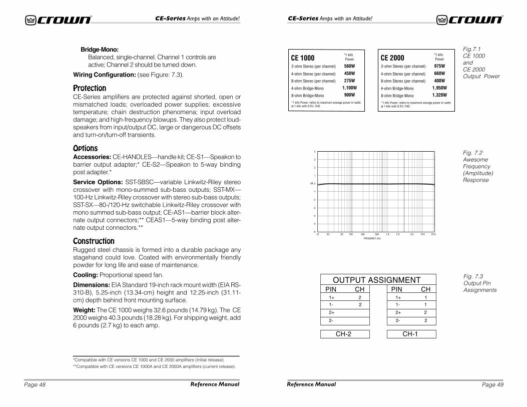
PowerOutput Power: (see Figure 7.1).
Load Impedance: Safe with all types of loads. Rated for 2, 4and 8 ohms in Stereo mode, 4 and 8 ohms in Bridge-Monomode.
Voltage Gain to 1-kHz, 8-ohm rated output,CE1000:
30.5-dB gain at 1.4-volt sensitivity;26-dB gain at 2.34-volt sensitivity.
CE2000:32.1-dB gain at 1.4-volt sensitivity;26-dB gain at 2.83-volt sensitivity.
Required AC Mains: 50/60 Hz (North American units are 60Hz only); 100-, 120- and 230-/240-VAC (±10%) units are avail-able.
AC Line Current;CE 1000:
100 Volts: 7.6 A;120 Volts: 6.3 A;230-240 Volts: 3.5 A;
CE 2000:100 Volts: 11.4 A;120 Volts: 9.5 A;230-240 Volts: 5.0 A;
At Idle: All amps draw no more than 90 watts.
AC Line Connector: NEMA 5-15P (15 A).
PerformanceFrequency Response: ±0.2 dB from 20 Hz to 25 kHz at 1 watt(See Figure 7.2).
Phase Response: ±15 degrees from 20 Hz to 20 kHz at 1watt.
Page 47
CE-Series Amps with an Attitude!
Page 46
CE-Series Amps with an Attitude!
Reference Manual Reference Manual
Signal to Noise Ratio,A-Weighted:
Better than 105 dB below rated 1-kHz power;
20 Hz to 20 kHz:Better than 100 dB below rated 1-kHz power.
Total Harmonic Distortion (THD): 0.5% or less true THD from 20Hz to 20 kHz.
Intermodulation Distortion (IMD): (60 Hz and 7 kHz at 4:1) Lessthan 0.1% at rated power to 35 dB below rated power at 8 ohms.
Damping Factor: Better than 400 from 10 Hz to 400 Hz.
Crosstalk: Better than 55 dB below rated power, 20 Hz to 20 kHz.
Common Mode Rejection (CMR): Better than 70 dB from 20 Hzto 1 kHz.
DC Output Offset (Shorted Input): ±10 mV.
Controls and ConnectorsLevel: A detented rotary level control for each channel located onthe front panel.
Power: An on/off rocker switch located on the front panel.
Mode: A two-position switch located on the back panel below theinput connectors which, when turned to stereo, operates the am-plifier as two independent channels. When “Bridge-Mono” modeis selected, the amplifier bridges the two output channels for twicethe output voltage.
Reset: A front-panel push button used to reset the circuit breakerthat protects the power supply.
Sensitivity: A two-position switch located on the back panel nextto the Mode switch. Switchable between 1.4 volts for full outputinto an 8-ohm load (default setting), or a fixed voltage gain of 26dB. 0.775-volt sensitivity available as a Service Option.
Fault Jack: A back-panel RJ-11 jack that may be remotely moni-tored to signal amplifier Fault condition. An LED or other signallingdevice (not supplied) may be used.
Indicators( All Located on the Front Panel)
Signal: A green LED for each channel which flashes when a verylow-level signal (>–40 dBm) is present at input. May be used fortroubleshooting cable runs.
Clip: A red LED for each channel which turns on when distortionbecomes audible in the amplifier output.
Fault: Normally off, this red indicator will blink under five differentconditions:
1. When the amplifier is first powered up, until the unit is readyfor operation.
2. If the heatsinks reach a temperature above normal workinglimits.
3. If the transformer thermal protection circuit is activated.
4. If amplifier output wires develop a short-circuit.
5. Should the amplifier output stage become non-operational.
This circuit may be monitored remotely by plugging a simpleswitching circuit using an LED or other signaling device into theback-panel RJ-11 (Fault) jack. Under some conditions, the outputof the amplifier will be muted.
Power: A green LED that turns on when the amplifier has beenturned on and has power.
Input/OutputInput Connector (standard module): One Neutrik® Combo con-nector for each channel which features a balanced ¼-inch (6.35-mm) phone jack and a 3-pin female XLR connector, in parallelwith a barrier strip termination.
Input Stage: Input is electronically balanced and employs preci-sion 1% resistors.
Input Impedance: Nominally 20 k ohms, balanced. Nominally 10k ohms, unbalanced.
Input Sensitivity: 1.4 volts for standard 1-kHz power, or fixed 26-dB gain. 0.775-volt sensitivity available as a Service Option.
Output Connectors: Two Neutrik® Speakon® NL4MP (mates withNL4FC) output connectors. Optional 5-way binding post or barrierstrip outputs (in parallel with Speakon® connectors) are availableas a Service Option.
DC Output Offset: ±10 millivolts.
Output Signal,Stereo:
Unbalanced, two-channel;
Page 49
CE-Series Amps with an Attitude!
Page 48
CE-Series Amps with an Attitude!
Reference Manual Reference Manual
Fig. 7.2AwesomeFrequency(Amplitude)Response
Bridge-Mono:Balanced, single-channel. Channel 1 controls areactive; Channel 2 should be turned down.
Wiring Configuration: (see Figure: 7.3).
ProtectionCE-Series amplifiers are protected against shorted, open ormismatched loads; overloaded power supplies; excessivetemperature; chain destruction phenomena; input overloaddamage; and high-frequency blowups. They also protect loud-speakers from input/output DC, large or dangerous DC offsetsand turn-on/turn-off transients.
OptionsAccessories: CE-HANDLES—handle kit; CE-S1—Speakon tobarrier output adapter;* CE-S2—Speakon to 5-way bindingpost adapter.*
Service Options: SST-SBSC—variable Linkwitz-Riley stereocrossover with mono-summed sub-bass outputs; SST-MX—100-Hz Linkwitz-Riley crossover with stereo sub-bass outputs;SST-SX—80-/120-Hz switchable Linkwitz-Riley crossover withmono summed sub-bass output; CE-AS1—barrier block alter-nate output connectors;** CEAS1—5-way binding post alter-nate output connectors.**
ConstructionRugged steel chassis is formed into a durable package anystagehand could love. Coated with environmentally friendlypowder for long life and ease of maintenance.
Cooling: Proportional speed fan.
Dimensions: EIA Standard 19-inch rack mount width (EIA RS-310-B), 5.25-inch (13.34-cm) height and 12.25-inch (31.11-cm) depth behind front mounting surface.
Weight: The CE 1000 weighs 32.6 pounds (14.79 kg). The CE2000 weighs 40.3 pounds (18.28 kg). For shipping weight, add6 pounds (2.7 kg) to each amp.
Fig. 7.3Output PinAssignments
Fig.7.1CE 1000andCE 2000Output Power
*Compatible with CE versions CE 1000 and CE 2000 amplifiers (initial release).
**Compatible with CE versions CE 1000A and CE 2000A amplifiers (current release).

Page 51
CE-Series Amps with an Attitude!
Page 50
CE-Series Amps with an Attitude!
Reference Manual Reference Manual
Send copies of the shipping receipts to Crown to receive reim-bursement.
Your repaired unit will be returned via UPS ground. Please con-tact us if other arrangements are required.
Factory Service Shipping Instructions:
1 When sending a Crown product to the factory for service,be sure to fill out the service information form found in theback of this manual and enclose it inside your unit’s ship-ping pack. Do not send the service information formseparately.
2 To ensure the safe transportation of your unit to the fac-tory, ship it in an original factory packing container. If youdon’t have one, call or write Crown’s Parts Department.Do not use loose, small size packing materials.
3 Do not ship the unit in any kind of cabinet or rack (wood ormetal). Ignoring this warning may result in extensive dam-age to the unit and the cabinet. Accessories are notneeded—do not send cables and other hardware. Do notsend this instruction manual, if we forget what we said, wehave duplicates!
If you have any questions, please call or write the Crown Tech-nical Support Group.
Crown Customer ServiceTechnical Support / Factory ServicePlant 2 SW, 1718 W. Mishawaka Rd., Elkhart,Indiana 46517 U.S.A.
Telephone: 219-294-8200800-342-6939 (North America, Puerto Rico, and Virgin Islands only)
Facsimile: 219-294-8301 (Technical Support)219-294-8124 (Factory Service)
Internet: http://www.crownaudio.com
Always use theoriginal factory
packing totransportthe unit.
8 ServiceYour amplifier should only be serviced by a fully trained techni-cian at an authorized service center.
CAUTION: To prevent electric shock, do not remove covers.No user serviceable parts inside. Refer servicing to a quali-fied technician.
Worldwide ServiceService may be obtained from an authorized service center.(Contact your local Crown/Amcron representative or our officefor a list of authorized service centers.) To obtain service, sim-ply present the bill of sale as proof of purchase along with thedefective unit to an authorized service center. They will handlethe necessary paperwork and repair.
Remember to transport your unit in the original factory pack-ing!
North American ServiceService may be obtained in one of two ways: from an autho-rized service center or from the factory. You may choose either.It is important that you have your copy of the bill of sale as yourproof of purchase.
Service at a North American Service CenterThis method usually saves the most time and effort. Simplypresent your bill of sale along with the defective unit to an au-thorized service center to obtain service. They will handle thenecessary paperwork and repair. Remember to transport theunit in the original factory packing. A list of authorized servicecenters in your area can be obtained from our Technical Sup-port Group.
Factory ServiceTo obtain factory service, fill out the service information pagefound in the back of this manual and send it along with yourproof of purchase and the defective unit to the Crown factory.
For warranty service, we will pay for ground shipping bothways in the United States. Contact Crown Factory Service orTechnical Support to obtain prepaid shipping labels prior tosending the unit. Or, if you prefer, you may prepay the cost ofshipping, and Crown will reimburse you.

WORLDWIDESUMMARY OF WARRANTY
The Crown Audio Division of Crown International, Inc., 1718 West Mishawaka Road,Elkhart, Indiana 46517-4095 U.S.A. warrants to you, the ORIGINAL PURCHASER andANY SUBSEQUENT OWNER of each NEW Crown1 product, for a period of three (3)years from the date of purchase by the original purchaser (the “warranty period”) thatthe new Crown product is free of defects in materials and workmanship, and we furtherwarrant the new Crown product regardless of the reason for failure, except asexcluded in this Crown Warranty.1 Note: If your unit bears the name “Amcron,” please substitute it for the name “Crown”in this warranty.
ITEMS EXCLUDED FROM THIS CROWN WARRANTYThis Crown Warranty is in effect only for failure of a new Crown product which occurredwithin the Warranty Period. It does not cover any product which has been damagedbecause of any intentional misuse, accident, negligence, or loss which is coveredunder any of your insurance contracts. This Crown Warranty also does not extend tothe new Crown product if the serial number has been defaced, altered, or removed.
WHAT THE WARRANTOR WILL DOWe will remedy any defect, regardless of the reason for failure (except as excluded),by repair, replacement, or refund. We may not elect refund unless you agree, or unlesswe are unable to provide replacement, and repair is not practical or cannot be timelymade. If a refund is elected, then you must make the defective or malfunctioningproduct available to us free and clear of all liens or other encumbrances. The refundwill be equal to the actual purchase price, not including interest, insurance, closingcosts, and other finance charges less a reasonable depreciation on the product fromthe date of original purchase. Warranty work can only be performed at our authorizedservice centers. We will remedy the defect and ship the product from the servicecenter within a reasonable time after receipt of the defective product at our authorizedservice center.
HOW TO OBTAIN WARRANTY SERVICEYou must notify us of your need for warranty service not later than ninety (90) days afterexpiration of the warranty period. All components must be shipped in a factory pack.Corrective action will be taken within a reasonable time of the date of receipt of thedefective product by our authorized service center. If the repairs made by ourauthorized service center are not satisfactory, notify our authorized service centerimmediately.
DISCLAIMER OF CONSEQUENTIAL & INCIDENTAL DAMAGESYOU ARE NOT ENTITLED TO RECOVER FROM US ANY INCIDENTAL DAMAGESRESULTING FROM ANY DEFECT IN THE NEW CROWN PRODUCT. THIS INCLUDESANY DAMAGE TO ANOTHER PRODUCT OR PRODUCTS RESULTING FROM SUCHA DEFECT.
WARRANTY ALTERATIONSNo person has the authority to enlarge, amend, or modify this Crown Warranty. ThisCrown Warranty is not extended by the length of time which you are deprived of theuse of the new Crown product. Repairs and replacement parts provided under theterms of this Crown Warranty shall carry only the unexpired portion of this CrownWarranty.
DESIGN CHANGESWe reserve the right to change the design of any product from time to time withoutnotice and with no obligation to make corresponding changes in products previouslymanufactured.
LEGAL REMEDIES OF PURCHASERNo action to enforce this Crown Warranty shall be commenced later than ninety (90)days after expiration of the warranty period.
THIS STATEMENT OF WARRANTY SUPERSEDES ANY OTHERSCONTAINED IN THIS MANUAL FOR CROWN PRODUCTS.
9/90
TH
RE
E Y
EA
RFU
LL W
AR
RA
NT
YYEAR3
Telephone: 219-294-8200. Facsimile: 219-294-8301
NORTH AMERICASUMMARY OF WARRANTY
The Crown Audio Division of Crown International, Inc., 1718 West Mishawaka Road,Elkhart, Indiana 46517-4095 U.S.A. warrants to you, the ORIGINAL PURCHASER andANY SUBSEQUENT OWNER of each NEW Crown product, for a period of three (3)years from the date of purchase by the original purchaser (the “warranty period”) thatthe new Crown product is free of defects in materials and workmanship. We furtherwarrant the new Crown product regardless of the reason for failure, except asexcluded in this Warranty.
ITEMS EXCLUDED FROM THIS CROWN WARRANTYThis Crown Warranty is in effect only for failure of a new Crown product which occurredwithin the Warranty Period. It does not cover any product which has been damagedbecause of any intentional misuse, accident, negligence, or loss which is coveredunder any of your insurance contracts. This Crown Warranty also does not extend tothe new Crown product if the serial number has been defaced, altered, or removed.
WHAT THE WARRANTOR WILL DOWe will remedy any defect, regardless of the reason for failure (except as excluded),by repair, replacement, or refund. We may not elect refund unless you agree, or unlesswe are unable to provide replacement, and repair is not practical or cannot be timelymade. If a refund is elected, then you must make the defective or malfunctioningproduct available to us free and clear of all liens or other encumbrances. The refundwill be equal to the actual purchase price, not including interest, insurance, closingcosts, and other finance charges less a reasonable depreciation on the product fromthe date of original purchase. Warranty work can only be performed at our authorizedservice centers or at the factory. We will remedy the defect and ship the product fromthe service center or our factory within a reasonable time after receipt of the defectiveproduct at our authorized service center or our factory. All expenses in remedying thedefect, including surface shipping costs in the United States, will be borne by us. (Youmust bear the expense of shipping the product between any foreign country and theport of entry in the United States and all taxes, duties, and other customs fees for suchforeign shipments.)
HOW TO OBTAIN WARRANTY SERVICEYou must notify us of your need for warranty service not later than ninety (90) days afterexpiration of the warranty period. All components must be shipped in a factory pack,which, if needed, may be obtained from us free of charge. Corrective action will betaken within a reasonable time of the date of receipt of the defective product by us orour authorized service center. If the repairs made by us or our authorized servicecenter are not satisfactory, notify us or our authorized service center immediately.
DISCLAIMER OF CONSEQUENTIAL & INCIDENTAL DAMAGESYOU ARE NOT ENTITLED TO RECOVER FROM US ANY INCIDENTAL DAMAGESRESULTING FROM ANY DEFECT IN THE NEW CROWN PRODUCT. THIS INCLUDESANY DAMAGE TO ANOTHER PRODUCT OR PRODUCTS RESULTING FROM SUCHA DEFECT. SOME STSOME STSOME STSOME STSOME STAAAAATES DO NOT ALLOW THE EXCLUSION OR LIMITTES DO NOT ALLOW THE EXCLUSION OR LIMITTES DO NOT ALLOW THE EXCLUSION OR LIMITTES DO NOT ALLOW THE EXCLUSION OR LIMITTES DO NOT ALLOW THE EXCLUSION OR LIMITAAAAATIONS OFTIONS OFTIONS OFTIONS OFTIONS OFINCIDENTINCIDENTINCIDENTINCIDENTINCIDENTAL OR CONSEQUENTIAL DAMAGES, SO THE ABOVE LIMITAL OR CONSEQUENTIAL DAMAGES, SO THE ABOVE LIMITAL OR CONSEQUENTIAL DAMAGES, SO THE ABOVE LIMITAL OR CONSEQUENTIAL DAMAGES, SO THE ABOVE LIMITAL OR CONSEQUENTIAL DAMAGES, SO THE ABOVE LIMITAAAAATION ORTION ORTION ORTION ORTION OREXCLUSION MAEXCLUSION MAEXCLUSION MAEXCLUSION MAEXCLUSION MAY NOT APPLY NOT APPLY NOT APPLY NOT APPLY NOT APPLY TO YOU.Y TO YOU.Y TO YOU.Y TO YOU.Y TO YOU.
WARRANTY ALTERATIONSNo person has the authority to enlarge, amend, or modify this Crown Warranty. ThisCrown Warranty is not extended by the length of time which you are deprived of theuse of the new Crown product. Repairs and replacement parts provided under theterms of this Crown Warranty shall carry only the unexpired portion of this CrownWarranty.
DESIGN CHANGESWe reserve the right to change the design of any product from time to time withoutnotice and with no obligation to make corresponding changes in products previouslymanufactured.
LEGAL REMEDIES OF PURCHASERTHIS CROWN WARRANTY GIVES YOU SPECIFIC LEGAL RIGHTS, YOU MAY ALSOHAVE OTHER RIGHTS WHICH VARY FROM STATE TO STATE. No action to enforce thisCrown Warranty shall be commenced later than ninety (90) days after expiration of thewarranty period.
THIS STATEMENT OF WARRANTY SUPERSEDES ANY OTHERSCONTAINED IN THIS MANUAL FOR CROWN PRODUCTS.
9/90
YEAR3
TH
RE
E Y
EA
RFU
LL W
AR
RA
NT
Y
Telephone: 219-294-8200. Facsimile: 219-294-8301

Crown Factory Service InformationShipping Address: Crown Audio, Inc., Factory Service,
Plant 2 SW, 1718 W. Mishawaka Rd., Elkhart, IN U.S.A. 46517Phone: 1-800-342-6939 or 1-219-294-8200 Fax: 1-219-294-8124
Owner’s Name: __________________________________________________________Shipping Address: ______________________________________________________Phone Number: _______________________ Fax Number: ___________________Model: _______________________________ Serial Number: _________________
Purchase Date: __________________________________________________________
NATURE OF PROBLEM(Be sure to describe the conditions that existed when the
problem occurred and what attempts were made to correct it.)
_______________________________________________________________________
_______________________________________________________________________
_______________________________________________________________________
_______________________________________________________________________
_______________________________________________________________________
Other equipment in your system: __________________________________________
_______________________________________________________________________
_______________________________________________________________________
_______________________________________________________________________
_______________________________________________________________________
If warranty has expired, payment will be:❏❏❏❏❏ Cash/Check ❏❏❏❏❏ VISA ❏❏❏❏❏ MasterCard ❏❏❏❏❏ C.O.D.
Card Number:___________________________
Exp. Date: __________ Signature:____________________________
ENCLOSE THIS PORTION WITH THE UNIT.DO NOT MAIL SEPARATELY.