Embed Size (px)
Citation preview
g20mdl1sm-REV0908 Model G20 Metallic
Engineering Data and Temperature Limitations ..................................................... 1
Explanation of Pump Nomenclature ...................................................................... 2
Performance Curve................................................................................................ 3
Dimensions ........................................................................................................... 4
Metric Dimensions ................................................................................................ 5
Principle of Pump Operation .................................................................................. 6
Installation and Start-Up ........................................................................................ 6
Natural Gas Supply ............................................................................................... 6
Natural Gas Valve Lubrication ............................................................................... 6
Natural Gas Line Moisture ..................................................................................... 6
Natural Gas Inlet and Priming ............................................................................... 6
Between Uses ....................................................................................................... 6
Installation Guide ................................................................................................... 7
Troubleshooting ..................................................................................................... 8
Warranty ................................................................................................................ 8
Recycling ............................................................................................................... 9
Important Safety Information ................................................................................. 9
Material Codes .................................................................................................... 10
Composite Repair Parts Drawing ........................................................................ 12
Available Service and Conversion Kits ................................................................ 12
Composite Repair Parts List ................................................................................ 13
Natural Gas Distribution Valve Assembly Drawing and Parts List ....................... 14
Natural Gas Distribution Valve Servicing ............................................................. 15
Pilot Valve Servicing, Assembly Drawing & Parts List ......................................... 16
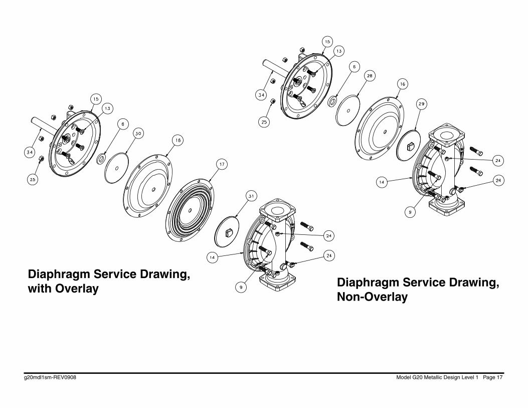
Diaphragm Service Drawing, with Overlay .......................................................... 17
Diaphragm Service Drawing, Non-Overlay .......................................................... 17
Diaphragm Servicing ........................................................................................... 18
Overlay Diaphragm Servicing ............................................................................. 18
Actuator Plunger Servicing .................................................................................. 19
Check Valve Servicing ......................................................................................... 20
Check Valve Drawing ........................................................................................... 20
Provision for Piping Gas Exhaust ........................................................................ 21
Pumping Hazardous Liquids ................................................................................ 21
Piping Exhaust Natural Gas ................................................................................ 21
Exhaust Illustration .............................................................................................. 21
Grounding The Pump .......................................................................................... 22
CE Declaration of Conformity ............................................................................. 23
SERVICE & OPERATING MANUAL
Model G20 Metallic Design Level 1
Table of Contents
WARREN RUPP®, INC. • A Unit of IDEX Corporation • P.O. Box 1568, Mansfi eld, Ohio 44901-1568 USA • Telephone (419) 524-8388 • Fax (419) 522-7867 • www.warrenrupp.com
©Copyright 2008 Warren Rupp, Inc. All rights reserved.
CEU.S. Patent #5,996,627; 6,241,487Other U.S. Patents Applied forNatural Gas-Operated Diaphragm Pumps
II 2GD T5

g20mdl1sm-REV0908 Model G20 Metallic Design Level 1 Page 1
Quality SystemISO9001 Certifi ed
Environmental Management System ISO14001 Certifi ed
G20 Metallic
Materials Maximum* Minimum* Operating Temperatures
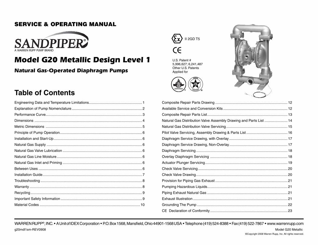
INTAKE/DISCHARGE PIPE SIZE2" NPT(internal)
2" BSP Tapered (internal)
CAPACITY0 to 150 gallons per minute(0 to 567 liters per minute)
GAS VALVENo-lube, no-stall
design
SOLIDS-HANDLINGUp to .25 in. (6mm)
HEADS UP TO100 psi or 230.7 ft. of water
(7 Kg/cm2 or 70 meters)
DISPLACEMENT/STROKE.42 Gallon / 1.59 liter
CAUTION! Operating temperature limitations are as follows:
ENGINEERING, PERFORMANCE& CONSTRUCTION DATA
For specifi c applications, always consult “Chemical Resistance Chart” Technical Bulletin
These G20 SANDPIPER® models are designed to be powered by natural gas. The minimum pump operating temperature is -10°F and the maximum pump operating temperature is 180°F.
Natural Gas-Operated Diaphragm Pumps
Nitrile: General purpose, oil-resistant. Shows good solvent, oil, water and hydraulic fluid resistance. Should not be used with highly polar solvents like acetone and MEK, ozone, chlorinated 190°F -10°F hydrocarbons and nitro hydrocarbons. 88°C -23°C
Virgin PTFE: Chemically inert, virtually impervious. Very few chemicals are known to react chemically with PTFE: molten alkali metals, turbulent liquid or gaseous fluorine and a few fluoro-chemicals such as 220°F -35°F chlorine trifluoride or oxygen difluoride which readily liberate free fluorine at elevated temperatures. 104°C -37°C
FKM (Fluorocarbon): Excellent resistance to sour natural gas, high temperatures, acids, hydrogen sulfide, and oils. 400°F -15°F 204°F -26°F
CEU.S. Patent #5,996,627; 6,241,487Other U.S. Patents Applied for
II 2GD T5
g20mdl1sm-REV0908 Model G20 Metallic Design Level 1 Page 2
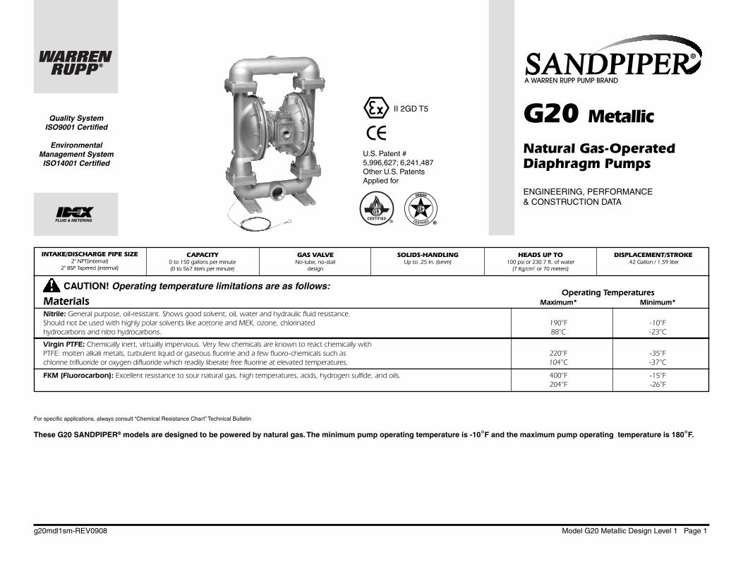
Check Diaphragm/ Check Non-Wetted Shipping MODEL Pump Pump Valve Design Wetted Check Valve Valve Material Porting Pump Pump Kit Weight Brand Size Type Level Material Materials Seat Options Options Style Options Options lbs. (kg)
G20B1ABBXNSX00. G 20 B 1 A B B X N S X 00. 69 (31) G20B1ATTXNSX00. G 20 B 1 A T T X N S X 00. 69 (31) G20B1SBBXNSX00. G 20 B 1 S B B X N S X 00. 114 (52) G20B1STTXNSX00. G 20 B 1 S T T X N S X 00. 114 (52) G20B1ABBXBSX00. G 20 B 1 A B B X B S X 00. 114 (52) G20B1ATTXBSX00. G 20 B 1 A T T X B S X 00. 114 (52) G20B1SBBXBSX00. G 20 B 1 S B B X B S X 00. 114 (52) G20B1STTXBSX00. G 20 B 1 S T T X B S X 00. 114 (52) G20B1SBBSNSX00. G 20 B 1 S B B S N S X 00. 114 (52) G20B1STTSNSX00. G 20 B 1 S T T S N S X 00. 114 (52) G20B1ABT0NSX00. G 20 B 1 A B T 0 N S X 00. 53 (34) G20B1ATT0NSX00. G 20 B 1 A T T 0 N S X 00. 53 (34) G20B1SBT0NSX00. G 20 B 1 S B T 0 N S X 00. 95 (43) G20B1STT0NSX00. G 20 B 1 S T T 0 N S X 00. 95 (43) G20B1SBT8NSX00. G 20 B 1 S B T 8 N S X 00. 145 (66) G20B1STT8NSX00. G 20 B 1 S T T 8 N S X 00. 145 (66)
Explanation of Pump Nomenclature · G20 Metallic · Design Level 1· Ball Valve
These pump models are designed to pump the following fl uids: Crude Oil, Salt Water, Drilling Mud, Condensate, Lubrication Oils, Glycol, Caustic liquids, and Acids.
Pump BrandG= Gas Operated
Pump Size20=2"
Check Valve TypeB= Ball
Design Level1= Design Level
Wetted MaterialS= Stainless SteelA= Aluminum
Diaphragm /Check Ball MaterialsB= Nitrile/NitrileT=PTFE -Nitrile/PTFE5=Nitrile/PTFE
Check Valve SeatB= NitrileT= PTFEA= AluminumS= Stainless Steel
Non-Wetted Material OptionsA= Painted AluminumX= Unpainted Aluminum0= Unpainted Aluminum/FKM ElastomersV= Unpainted Aluminum/FKM ElastomersS= Stainless Steel7= Painted Stainless Steel8= Stainless Steel/FKM Elastomers 9= Painted Stainless Steel/FKM Elastomers
Porting OptionsN= NPT ThreadsB= BSP (Tapered) Threads
Pump StyleS= Standard
Pump OptionsX= No Muffl er Permitted *
* The exhausted natural gas must be vented to a low pressure safe location in accordance with local fi re safety and environmental codes, an industry or nationally recognized code having jurisdiction over the specifi c installations, and/or CAN/CGA B149, Installation Codes.
Note: Models listed in the table are for reference only. See nomenclature below for other models.

g20mdl1sm-REV0908 Model G20 Metallic Design Level 1 Page 3
Performance Curve, G20 Model Metallic Design Level 1
0 20 40 60 80 100 120 140 160
20 (34)
40 (68)
60 (102)
80 (136)
100 (170)
6005004003002001000
CAPACITY
U.S. Gallons per minute
Liters per minute
100
90
80
70
60
50
40
30
20
10
0
BA
R
PS
I
HE
AD
1
2
3
4
5
6
7
0
30
2025
1015
5
9.1
67.6
34.5
1.5
NP
SH
RM
ET
ER
S
FE
ET
40 PSI (2.72 Bar)
20 PSI (1.36 Bar)Gas Inlet Pressure
60 PSI (4.08 Bar)
80 PSI (5.44 Bar)
100 PSI (6.8 Bar)
MODEL G20 Metallic Performance CurvePerformance based on the following: elastomer fitted pump, flooded suction, water at ambient conditions.
The use of other materials and varying hydraulic conditions may result in deviations in excess of 5%.
g20mdl1sm-REV0908 Model G20 Metallic Design Level 1 Page 4
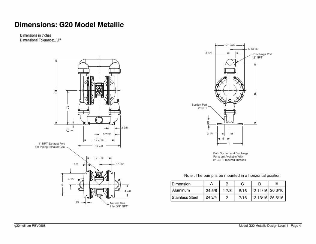
Dimensions: G20 Model Metallic Dimensions in InchesDimensional Tolerance:±1/8"
12 19/325 13/16
Discharge Port2" NPT
2 1/4
Suction Port2" NPT
2 1/4
5
1
Both Suction and Discharge Ports are Available With 2" BSPT Tapered Threads
2 3/8
6 7/32
12 7/16
16 7/81" NPT Exhaust Port
For Piping Exhaust Gas
10 1/16
5 1/321/2
4 1/2
9
4 7/8
1/2 Natural Gas Inlet 3/4" NPT
A
B
E
D
C
Stainless Steel
Dimension A B C D E
Aluminum 24 5/8 1 7/8 5/16 13 11/16 26 3/16
24 3/4 2 7/16 13 13/16 26 5/16
Note : The pump is be mounted in a horizontal position
g20mdl1sm-REV0908 Model G20 Metallic Design Level 1 Page 5
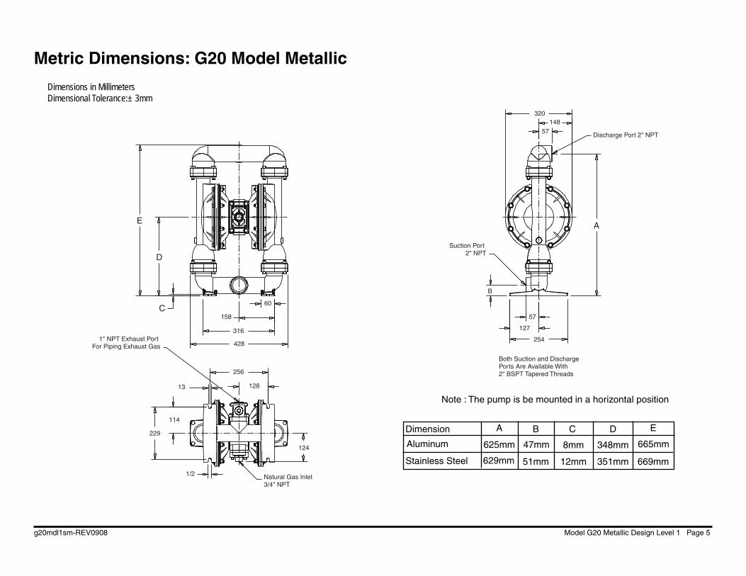
Metric Dimensions: G20 Model Metallic
60
158
316
4281" NPT Exhaust Port
For Piping Exhaust Gas
256
12813
114
229
1/2 Natural Gas Inlet 3/4" NPT
124
254
127
57
Suction Port 2" NPT
Both Suction and Discharge Ports Are Available With 2" BSPT Tapered Threads
Discharge Port 2" NPT57
148320
A
B
E
D
C
Dimensions in MillimetersDimensional Tolerance:± 3mm
Stainless Steel
Dimension A B C D E
Aluminum 625mm 47mm 8mm 348mm 665mm
629mm 51mm 12mm 351mm 669mm
Note : The pump is be mounted in a horizontal position
g20mdl1sm-REV0908 Model G20 Metallic Design Level 1 Page 6
is reversed. The gas distribution valve spool is moved by a internal pilot valve which alternately pressurizes one end of the valve while exhausting the other end. The pilot valve is shifted at each end of the diaphragm stroke when a actuator plunger is contacted by the diaphragm plate. This actuator plunger then pushes the end of the pilot valve spool into position to activate the gas distribution valve.
The chambers are connected with manifolds with a suction and discharge check valve for each chamber, maintaining fl ow in one direction through the pump.
INSTALLATION AND START-UPLocate the pump as close to the
product being pumped as possible. Keep the suction line length and number of fi ttings to a minimum. Do not reduce the suction line diameter.
For installations of rigid piping, short sections of flexible conductive hose should be installed between the pump and the piping. The fl exible conductive hose reduces vibration and strain to the pumping system. A surge suppressor is recommended to further reduce pulsation in fl ow.
NATURAL GAS SUPPLYNatural gas inlet pressure must be
regulated to 100 (7 bar) psi with a pressure regulator. Connect the pump gas inlet to an gas supply of sufficient capacity and pressure required for desired performance. When the gas supply line is solid piping, use a short length of fl exible conductive hose not less than 3/4" (19mm) in diameter between
PRINCIPLE OF PUMP OPERATIONThis ball type check valve pump is
powered by sweet natural gas and is a 1:1 ratio design. The inner side of one diaphragm chamber is alternately pressurized while simultaneously exhausting the other inner chamber. This causes the diaphragms, which are connected by a common rod secured by plates to the centers of the diaphragms, to move in a reciprocating action. (As one diaphragm performs the discharge stroke the other diaphragm is pulled to perform the suction stroke in the opposite chamber.) Gas pressure is applied over the entire inner surface of the diaphragm while liquid is discharged from the opposite side of the diaphragm. The diaphragm operates in a balanced condition during the discharge stroke which allows the pump to be operated at discharge heads over 200 feet (61 meters) of water.
For maximum diaphragm life, keep the pump as close to the liquid being pumped as possible. Positive suction head in excess of 10 feet of liquid (3.048 meters) may require a back pressure regulating device to maximize diaphragm life.
A l te r na te p ressur i z ing and exhausting of the diaphragm chamber is performed by an externally mounted, pilot operated, four way spool type gas distribution valve. When the spool shifts to one end of the valve body, inlet pressure is applied to one diaphragm chamber and the other diaphragm chamber exhausts. When the spool shifts to the opposite end of the valve body, the pressure to the chambers
the pump and the piping to reduce strain to the piping. The weight of the gas supply line, regulators and fi lters must be supported by some means other than the gas inlet cap. Failure to provide support for the piping may result in damage to the pump. A pressure regulating valve should be installed to insure gas supply pressure does not exceed recommended limits.
VALVE LUBRICATIONThe natural gas distribution valve
and the pilot valve are designed to operate WITHOUT lubrication. This is the preferred mode of operation. There may be instances of personal preference or poor quality gas supplies when lubrication of the supply is required. The pump system will operate with properly lubricated supply. Proper lubrication requires the use of an gas line lubricator (available from Warren Rupp) set to deliver one drop of SAE 10 non-detergent oil for every 20 SCFM (9.4 liters/sec.) of gas the pump consumes at the point of operation. Consult the pump’s published Performance Curve to determine this.
GAS INLET AND PRIMINGTo start the pump, open the gas
valve approximately 1/2" to 3/4" turn. After the pump primes, the valve can be opened to increase gas flow as desired. If opening the valve increases cycling rate, but does not increase the rate of fl ow, cavitation has occurred. The valve should be closed slightly to obtain the most effi cient gas fl ow to pump fl ow ratio.
BETWEEN USESWhen the pump is used for materials
that tend to settle out or solidify when not in motion, the pump should be flushed after each use to prevent damage. (Product remaining in the pump between uses could dry out or settle out. This could cause problems with the diaphragms and check valves at restart.) In freezing temperatures the pump must be completely drained between uses in all cases.
Natural gas exhaust is to be vented to low pressure safe location using conductive nitrile rubber hose or metal piping in accordance with
local fire and environmental codes, or an industry or nationally recognized code having jurisdiction over specifi c installations, and/or CAN/CGA B149, Installation Codes.
WARNING
g20mdl1sm-REV0908 Model G20 Metallic Design Level 1 Page 7
CAUTIONThe natural gas exhaust must be piped to an area for safe disposition of the product being pumped, in the event of a diaphragm failure. (See page 23)
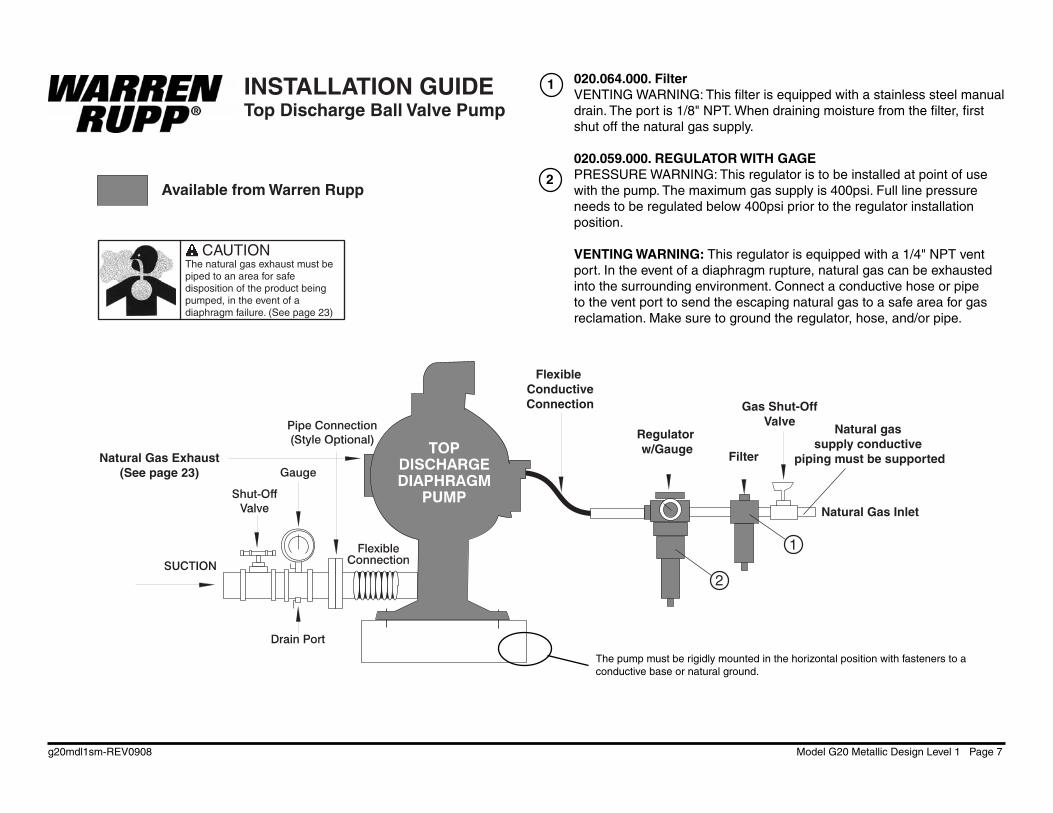
INSTALLATION GUIDETop Discharge Ball Valve Pump
Natural Gas Exhaust(See page 23)
Available from Warren Rupp
Natural Gas Inlet
Natural gas supply conductive
piping must be supported
Gas Shut-OffValve
2
1
Flexible ConductiveConnection
Regulator w/Gauge
Filter
The pump must be rigidly mounted in the horizontal position with fasteners to a conductive base or natural ground.
020.064.000. FilterVENTING WARNING: This fi lter is equipped with a stainless steel manual drain. The port is 1/8" NPT. When draining moisture from the fi lter, fi rst shut off the natural gas supply.
020.059.000. REGULATOR WITH GAGEPRESSURE WARNING: This regulator is to be installed at point of use with the pump. The maximum gas supply is 400psi. Full line pressure needs to be regulated below 400psi prior to the regulator installation position.
VENTING WARNING: This regulator is equipped with a 1/4" NPT vent port. In the event of a diaphragm rupture, natural gas can be exhausted into the surrounding environment. Connect a conductive hose or pipe to the vent port to send the escaping natural gas to a safe area for gas reclamation. Make sure to ground the regulator, hose, and/or pipe.
1
2
g20mdl1sm-REV0908 Model G20 Metallic Design Level 1 Page 8
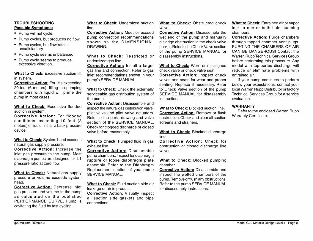
TROUBLESHOOTINGPossible Symptoms:• Pump will not cycle.• Pump cycles, but produces no fl ow.• Pump cycles, but fl ow rate is
unsatisfactory.• Pump cycle seems unbalanced.• Pump cycle seems to produce
excessive vibration.
What to Check: Excessive suction lift in system.Corrective Action: For lifts exceeding 20 feet (6 meters), fi lling the pumping chambers with liquid will prime the pump in most cases.
What to Check: Excessive flooded suction in system.Corrective Action: For f looded condit ions exceeding 10 feet (3 meters) of liquid, install a back pressure device.
What to Check: System head exceeds natural gas supply pressure.Corrective Action: Increase the inlet gas pressure to the pump. Most diaphragm pumps are designed for 1:1 pressure ratio at zero fl ow.
What to Check: Natural gas supply pressure or volume exceeds system head.Corrective Action: Decrease inlet gas pressure and volume to the pump as calculated on the publ ished PERFORMANCE CURVE. Pump is cavitating the fl uid by fast cycling.
What to Check: Undersized suction line.Corrective Action: Meet or exceed pump connection recommendations shown on the D IMENSIONAL DRAWING.
What to Check: Restr ic ted or undersized gas line.Corrective Action: Install a larger gas line and connection. Refer to gas inlet recommendations shown in your pump’s SERVICE MANUAL.
What to Check: Check the externally serviceable gas distribution system of the pump.Corrective Action: Disassemble and inspect the natural gas distribution valve, pilot valve and pilot valve actuators. Refer to the parts drawing and valve section of the SERVICE MANUAL. Check for clogged discharge or closed valve before reassembly.
What to Check: Pumped fl uid in gas exhaust line.Corrective Action: Disassemble pump chambers. Inspect for diaphragm rupture or loose diaphragm plate assembly. Refer to the Diaphragm Replacement section of your pump SERVICE MANUAL.
What to Check: Fluid suction side air leakage or air in product.Corrective Action: Visually inspect all suction side gaskets and pipe connections.
What to Check: Obstructed check valve.Corrective Action: Disassemble the wet end of the pump and manually dislodge obstruction in the check valve pocket. Refer to the Check Valve section of the pump SERVICE MANUAL for disassembly instructions.
What to Check: Worn or misaligned check valve or check valve seat.Corrective Action: Inspect check valves and seats for wear and proper seating. Replace if necessary. Refer to Check Valve section of the pump SERVICE MANUAL for disassembly instructions.
What to Check: Blocked suction line.Corrective Action: Remove or fl ush obstruction. Check and clear all suction screens and strainers.
What to Check: Blocked discharge line.Correct ive Act ion: Check for obstruction or closed discharge line valves.
What to Check: Blocked pumping chamber.Corrective Action: Disassemble and inspect the wetted chambers of the pump. Remove or fl ush any obstructions. Refer to the pump SERVICE MANUAL for disassembly instructions.
What to Check: Entrained air or vapor lock in one or both fluid pumping chambers.Corrective Action: Purge chambers through tapped chamber vent plugs. PURGING THE CHAMBERS OF AIR CAN BE DANGEROUS! Contact the Warren Rupp Technical Services Group before performing this procedure. Any model with top-ported discharge will reduce or eliminate problems with entrained air.
If your pump continues to perform below your expectations, contact your local Warren Rupp Distributor or factory Technical Services Group for a service evaluation.
WARRANTYRefer to the enclosed Warren Rupp
Warranty Certifi cate.
g20mdl1sm-REV0908 Model G20 Metallic Design Level 1 Page 9
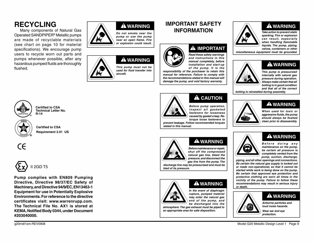
RECYCLINGMany components of Natural Gas
Operated SANDPIPER® Metallic pumps are made of recyclable materials (see chart on page 10 for material specifi cations). We encourage pump users to recycle worn out parts and pumps whenever possible, after any hazardous pumped fl uids are thoroughly fl ushed.
This pump is pressurized internally with natural gas pressure during operation. Always make certain that all bolting is in good condition and that all of the correct
bolting is reinstalled during assembly.
WARNING
Before pump operation, i n s p e c t a l l g a s k e t e d fasteners for looseness caused by gasket creep. Re-torque loose fasteners to
prevent leakage. Follow recommended torques stated in this manual.
CAUTION
When used for toxic or aggressive fl uids, the pump should always be fl ushed clean prior to disassembly.
WARNING
Before maintenance or repair, shut off the compressed natural gas line, bleed the pressure, and disconnect the gas line from the pump. The
discharge line may be pressurized and must be bled of its pressure.
WARNING
Take action to prevent static sparking. Fire or explosion can result , especial ly when handling fl ammable liquids. The pump, piping, valves, containers or other
miscellaneous equipment must be grounded.
WARNING
IMPORTANTRead these safety warnings and instructions in this manual completely, before installation and start-up of the pump. I t is the
responsibility of the purchaser to retain this manual for reference. Failure to comply with the recommendations stated in this manual will damage the pump, and void factory warranty.
WARNINGAirborne particles and loud noise hazards.
Wear ear and eye protection.
B e f o r e d o i n g a n y maintenance on the pump, be certain all pressure is completely vented from the pump, suction, discharge,
piping, and all other openings and connections. Be certain the natural gas supply is locked out or made non-operational, so that it cannot be started while work is being done on the pump. Be certain that approved eye protection and protective clothing are worn all times in the vicinity of the pump. Failure to follow these recommendations may result in serious injury or death.
WARNING
WARNINGIn the event of diaphragm rupture, pumped material may enter the natural gas end of the pump, and be discharged into the
atmosphere. The gas exhaust must be piped to an appropriate area for safe disposition.
IMPORTANT SAFETY INFORMATION
Do not smoke near the pump or use the pump near an open flame. Fire or explosion could result.
WARNING
This pump must not be used for fl uid transfer into aircraft.
WARNING
II 2GD T5
Pump complies with EN809 Pumping Directive, Directive 98/37/EC Safety of Machinery, and Directive 94/9/EC, EN13463-1 Equipment for use in Potentially Explosive Environments. For reference to the directive certifi cates visit: www.warrenrupp.com. The Technical File No. AX1 is stored at KEMA, Notifi ed Body 0344, under Document #203040000.
CE
Certifi ed to CSA Technical Letter No. R-14
Certifi ed to CSA
Requirement 2.01 US
g20mdl1sm-REV0908 Model G20 Metallic Design Level 1 Page 10
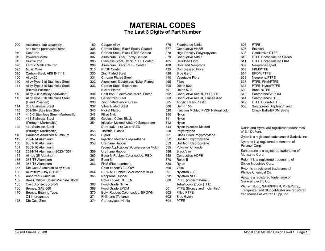
MATERIAL CODESThe Last 3 Digits of Part Number
g20mdl1sm-REV0908 Model G20 Metallic Design Level 1 Page 11

g20mdl1sm-REV0908 Model G20 Metallic Design Level 1 Page 12
Composite Repair Parts DrawingAvailable Service Kits:476.227.000 Gas End Kit Seals, O-Rings, Gaskets, Retaining Rings, Gas Valve Assembly and Pilot Valve Assembly476.227.363 Gas End Kit FKM Seals, O-Rings, Gaskets, Retaining Rings, Gas Valve Assembly and Pilot Valve Assembly476.206.360 Wetted End Kit Nitrile Diaphragms, Nitrile Check Balls and Nitrile Check Valve Seats476.206.649 Wetted End Kit Nitrile Diaphragms, PTFE Overlay Diaphragms, PTFE Check Balls and PTFE Check Valve Seats476.206.672 Wetted End Kit Nitrile Diaphragms, PTFE Check Balls, PTFE Seats

g20mdl1sm-REV0908 Model G20 Metallic Design Level 1 Page 13
ITEM PART NUMBER DESCRIPTION QTY 1 031-183-000 Gas Valve Assembly 1 031-183-363 Gas Valve Assembly 1 031-179-000 Gas Valve Assembly (Stainless Steel Midsection) 1 031-179-363 Gas Valve Assembly (Stainless Steel Midsection) 1 2 050-017-360 Ball, Check 4 050-018-600 Ball, Check 4 3 070-006-170 Bushing 2 4 095-110-000 Pilot Valve Assembly 1 095-110-363 Pilot Valve Assembly 1 095-110-110 Pilot Valve Assembly (Stainless Steel Midsection) 1 095-110-363SS Pilot Valve Assembly (Stainless Steel Midsection) 1 5 114-024-157 Intermediate Bracket 1 114-024-110 Intermediate Bracket (Stainless Steel Midsection) 1 6 132-035-360 Bumper, Diaphragm 2 132-035-363 Bumper, Diaphragm 2 7 135-034-506 Bushing, Plunger 2 8 165-116-157 Cap, Gas Inlet Assembly 1 165-116-110 Cap, Gas Inlet Assembly (Stainless Steel Midsection) 1 9 170-023-330 Capscrew, Hex Hd 7/16-14 X 1.75 16 170-023-115 Capscrew, Hex Hd 7/16-14 X 1.75 16 (Stainless Steel Midsection) 10 170-052-330 Capscrew, Hex Hd 3/8-16 X 2.25 16 170-052-115 Capscrew, Hex Hd 3/8-16 X 2.25 16 (Stainless Steel Midsection) 11 170-069-330 Capscrew, Hex Hd 5/16-18 X 1.75 4 170-069-115 Capscrew, Hex Hd 5/16-18 X 1.75 4 (Stainless Steel Midsection) 12 170-006-330 Capscrew, Hex Hd 3/8-16 X 1.00 4 170-006-115 Capscrew, Hex Hd 3/8-16 X 1.00 4 (Stainless Steel Midsection) 13 171-059-330 Capscrew, Soc Hd 7/16-14 X 1.25 8 171-011-115 Capscrew, Soc Hd 1/2-13 X 1.00 8 (Stainless Steel Midsection) 14 196-167-156 Chamber, Outer 2 196-167-110 Chamber, Outer 2 15 196-168-156 Chamber, Inner 2 196-168-110 Chamber, Inner (Stainless Steel Midsection) 2 16 286-007-360 Diaphragm 2 17 286-020-604 Diaphragm, Overlay 2 18 360-093-360 Gasket, Natural Gas Valve 1 19 360-103-360 Gasket, Pilot Valve 1
ITEM PART NUMBER DESCRIPTION QTY 20 360-104-379 Gasket, Natural Gas Inlet 1 21 360-105-360 Gasket, Inner Chamber 2 22 518-145-156 Manifold, Suction 1 518-145-156E Manifold, Suction 2" BSP 1 518-145-110 Manifold, Suction 1 518-145-110E Manifold, Suction 2" BSP 1 23 518-146-156 Manifold, Discharge 1 518-146-156E Manifold, Discharge 2" BSP 1 518-146-110 Manifold, Discharge 1 518-146-110E Manifold, Discharge 2" BSP 1 24 545-005-330 Nut, Hex 3/8-16 16 545-005-115 Nut, Hex 3/8-16 (Stainless Steel Midsection) 16 25 545-007-330 Nut, Hex 7/16-14 16 545-007-115 Nut, Hex 7/16-14 (Stainless Steel Midsection) 16 26 560-001-379 O-Ring 2 560-001-363 O-Ring 2 28 612-192-157 Plate, Inner Diaphragm 2 612-192-334 Plate, Inner Diaphragm (Stainless Steel Midsection) 2 29 612-194-156 Plate, Outer Diaphragm Assembly 2 612-194-110 Plate, Outer Diaphragm Assembly 2 30 612-195-157 Plate, Inner Diaphragm (PTFE overlays only) 2 612-195-334 Plate, Inner Diaphragm (Stainless Steel Midsection) 2 31 612-039-157 Plate, Outer Diaphragm (PTFE overlays only) 2 612-097-110 Plate, Diaphragm (PTFE overlays only) 2 32 620-020-115 Plunger, Actuator 2 33 675-042-115 Ring, Retaining 2 34 685-058-110 Rod, Diaphragm 1 35 720-004-360 Seal, Diaphragm Rod 2 720-004-363 Seal, Diaphragm Rod 2 36 722-040-360 Seat, Check Ball 4 722-040-600 Seat, Check Ball 4 722-040-110 Seat, Ckeck Ball (requires seals, see item 39) 4 722-040-150 Seat, Ckeck Ball (requires seals, see item 39) 4 37 900-005-330 Washer, Lock 16 900-005-115 Washer, Lock (Stainless Steel Midsection) 16 38 920-025-000 Ground Strap 1 39 560-106-360 O-Ring (use with metal seats) 8 720-060-608 Seal (use with metal seats) 8
g20mdl1sm-REV0908 Model G20 Metallic Design Level 1 Page 14
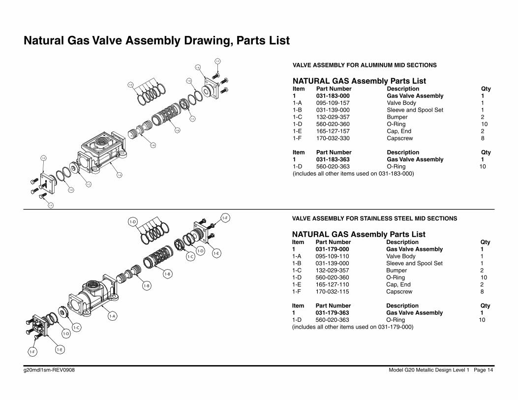
Natural Gas Valve Assembly Drawing, Parts List
VALVE ASSEMBLY FOR ALUMINUM MID SECTIONS
NATURAL GAS Assembly Parts List Item Part Number Description Qty1 031-183-000 Gas Valve Assembly 1 1-A 095-109-157 Valve Body 11-B 031-139-000 Sleeve and Spool Set 11-C 132-029-357 Bumper 21-D 560-020-360 O-Ring 101-E 165-127-157 Cap, End 21-F 170-032-330 Capscrew 8
Item Part Number Description Qty1 031-183-363 Gas Valve Assembly 11-D 560-020-363 O-Ring 10(includes all other items used on 031-183-000)
VALVE ASSEMBLY FOR STAINLESS STEEL MID SECTIONS
NATURAL GAS Assembly Parts List Item Part Number Description Qty1 031-179-000 Gas Valve Assembly 1 1-A 095-109-110 Valve Body 11-B 031-139-000 Sleeve and Spool Set 11-C 132-029-357 Bumper 21-D 560-020-360 O-Ring 101-E 165-127-110 Cap, End 21-F 170-032-115 Capscrew 8
Item Part Number Description Qty1 031-179-363 Gas Valve Assembly 11-D 560-020-363 O-Ring 10(includes all other items used on 031-179-000)
1-A
1-B
1-B
1-C
1-D
1-D
1-E
1-E
1-F
1-F
1-D
1-C
1-B
1-A
1-B
1-F
1-F
1-E
1-E
1-C
1-C
1-D
1-D
1-D
g20mdl1sm-REV0908 Model G20 Metallic Design Level 1 Page 15
Read these instructions complete ly, before installation and start-up. It is the responsibility of the purchaser to retain
this manual for reference. Failure to comply with the recommendations stated in this manual will damage the pump, and void factory warranty.
IMPORTANTNATURAL GAS DISTRIBUTION VALVE SERVICING
To service the natural gas valve fi rst shut off the compressed air, bleed pressure from the pump, and disconnect the gas supply line from the pump.
Step #1: See COMPOSITE REPAIR PARTS DRAWING.
Using a 9/16" wrench or socket, remove the four hex capscrews (items 12). Remove the gas valve assembly from the pump.
Remove and inspect gasket (item 18) for cracks or damage. Replace gasket if needed.
Step #2: Disassembly of the gas valve.
Using a 7/16" wrench or socket, remove the eight hex capscrews (items 1-F) that fasten the end caps to the valve body. Next remove the two end caps (items 1-E). Inspect the two o-rings (items 1-D) on each end cap for damage or wear. Replace the o-rings as needed.
Remove the bumpers (items 1-C). Inspect the bumpers for damage or wear. Replace the o-rings as needed.
Remove the spool (part of item 1-B) from the sleeve. Be careful not to scratch or damage the outer diameter of the spool. Wipe spool with a soft cloth and inspect for scratches or wear.
Inspect the inner diameter of the sleeve (part of item 1-B) for dir t, scratches, or other contaminants. Remove the sleeve if needed and replace with a new sleeve and spool set (item 1-A).
Step #3: Reassembly of the gas valve.
Install one bumper (item 1-C) and one end cap (item 1-E), with two o-rings (items 1-D), and fasten with four hex capscrews (items 1-F) to the valve body (item 1-A).
Remove the new sleeve an spool set (item 1-B) from the plastic bag. Carefully remove the spool from the sleeve. Install the six o-rings (item 1-D) into the six grooves on the sleeve. Apply a light coating of grease to the o-rings before installing the sleeve into the valve body (item 1-A), align the slots in the sleeve with the slots in the valve body. Insert the spool into the sleeve. Be careful not to scratch or damage the spool during installation. Install the remaining bumper, end cap (with o-rings), and fasten with the remaining hex capscrews.
Fasten the natural gas valve assembly (item 1) and gasket to the pump. Connect the compressed gas line to the pump. The pump is now ready for operation.
g20mdl1sm-REV0908 Model G20 Metallic Design Level 1 Page 16
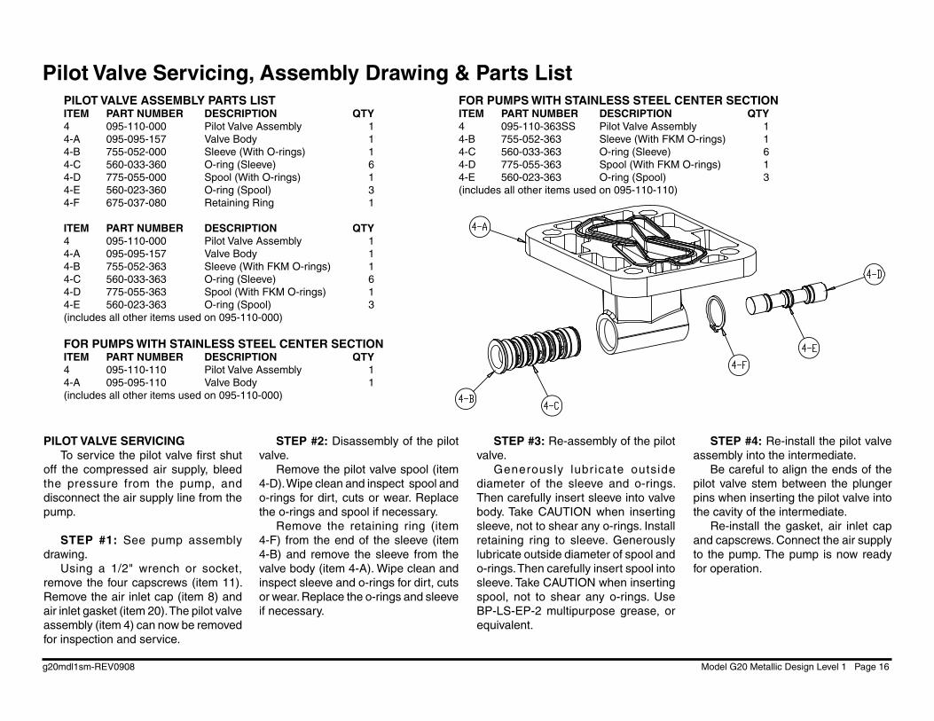
PILOT VALVE SERVICING To service the pilot valve fi rst shut
off the compressed air supply, bleed the pressure from the pump, and disconnect the air supply line from the pump.
STEP #1: See pump assembly
drawing.Using a 1/2" wrench or socket,
remove the four capscrews (item 11). Remove the air inlet cap (item 8) and air inlet gasket (item 20). The pilot valve assembly (item 4) can now be removed for inspection and service.
STEP #2: Disassembly of the pilot valve.
Remove the pilot valve spool (item 4-D). Wipe clean and inspect spool and o-rings for dirt, cuts or wear. Replace the o-rings and spool if necessary.
Remove the retaining ring (item 4-F) from the end of the sleeve (item 4-B) and remove the sleeve from the valve body (item 4-A). Wipe clean and inspect sleeve and o-rings for dirt, cuts or wear. Replace the o-rings and sleeve if necessary.
STEP #3: Re-assembly of the pilot valve.
Generously lubr icate outside diameter of the sleeve and o-rings. Then carefully insert sleeve into valve body. Take CAUTION when inserting sleeve, not to shear any o-rings. Install retaining ring to sleeve. Generously lubricate outside diameter of spool and o-rings. Then carefully insert spool into sleeve. Take CAUTION when inserting spool, not to shear any o-rings. Use BP-LS-EP-2 multipurpose grease, or equivalent.
STEP #4: Re-install the pilot valve assembly into the intermediate.
Be careful to align the ends of the pilot valve stem between the plunger pins when inserting the pilot valve into the cavity of the intermediate.
Re-install the gasket, air inlet cap and capscrews. Connect the air supply to the pump. The pump is now ready for operation.
Pilot Valve Servicing, Assembly Drawing & Parts ListPILOT VALVE ASSEMBLY PARTS LISTITEM PART NUMBER DESCRIPTION QTY4 095-110-000 Pilot Valve Assembly 14-A 095-095-157 Valve Body 14-B 755-052-000 Sleeve (With O-rings) 14-C 560-033-360 O-ring (Sleeve) 64-D 775-055-000 Spool (With O-rings) 14-E 560-023-360 O-ring (Spool) 34-F 675-037-080 Retaining Ring 1
ITEM PART NUMBER DESCRIPTION QTY4 095-110-000 Pilot Valve Assembly 14-A 095-095-157 Valve Body 14-B 755-052-363 Sleeve (With FKM O-rings) 14-C 560-033-363 O-ring (Sleeve) 64-D 775-055-363 Spool (With FKM O-rings) 14-E 560-023-363 O-ring (Spool) 3(includes all other items used on 095-110-000)
FOR PUMPS WITH STAINLESS STEEL CENTER SECTIONITEM PART NUMBER DESCRIPTION QTY4 095-110-110 Pilot Valve Assembly 14-A 095-095-110 Valve Body 1(includes all other items used on 095-110-000)
FOR PUMPS WITH STAINLESS STEEL CENTER SECTIONITEM PART NUMBER DESCRIPTION QTY4 095-110-363SS Pilot Valve Assembly 14-B 755-052-363 Sleeve (With FKM O-rings) 14-C 560-033-363 O-ring (Sleeve) 64-D 775-055-363 Spool (With FKM O-rings) 14-E 560-023-363 O-ring (Spool) 3(includes all other items used on 095-110-110)
g20mdl1sm-REV0908 Model G20 Metallic Design Level 1 Page 17
Diaphragm Service Drawing, Non-Overlay
Diaphragm Service Drawing, with Overlay
g20mdl1sm-REV0908 Model G20 Metallic Design Level 1 Page 18
Read these instructions complete ly, before installation and start-up. It is the responsibility of the purchaser to retain
this manual for reference. Failure to comply with the recommendations stated in this manual will damage the pump, and void factory warranty.
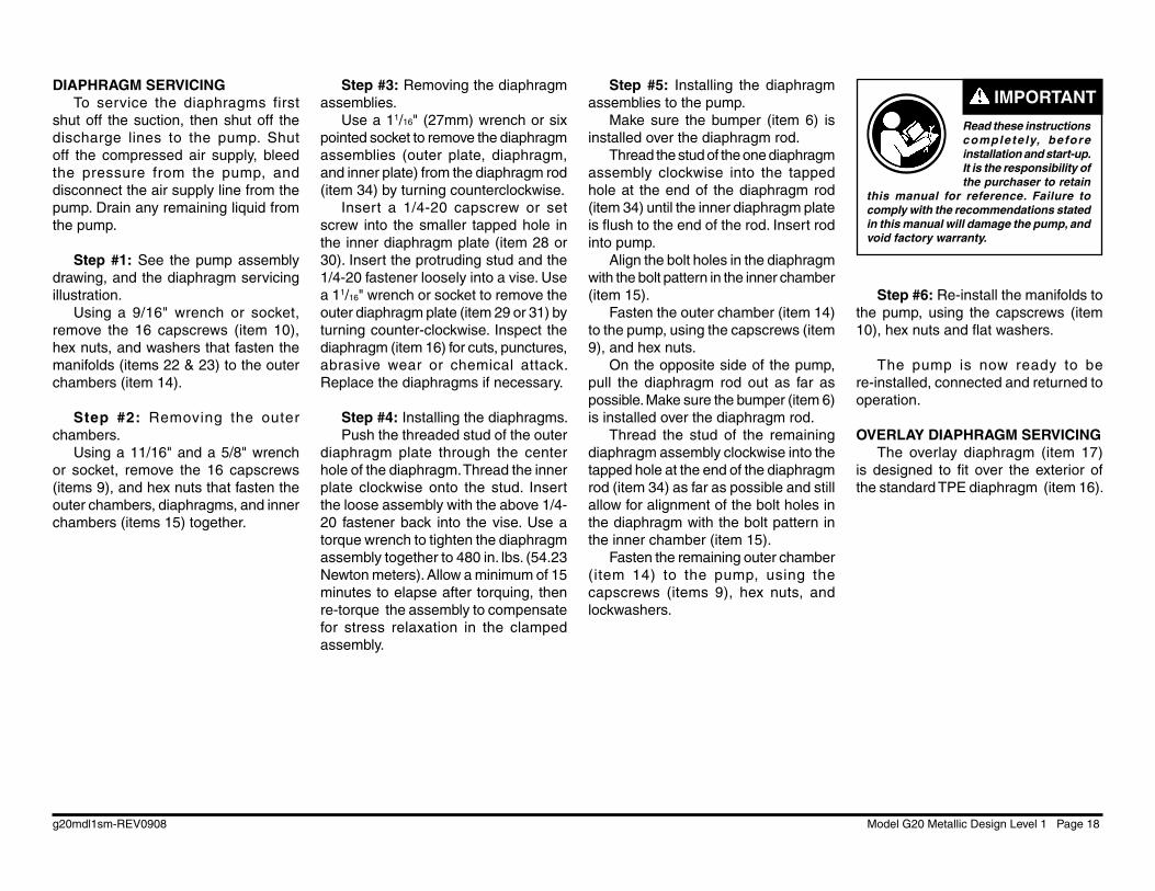
IMPORTANTDIAPHRAGM SERVICING
To service the diaphragms first shut off the suction, then shut off the discharge lines to the pump. Shut off the compressed air supply, bleed the pressure from the pump, and disconnect the air supply line from the pump. Drain any remaining liquid from the pump.
Step #1: See the pump assembly drawing, and the diaphragm servicing illustration.
Using a 9/16" wrench or socket, remove the 16 capscrews (item 10), hex nuts, and washers that fasten the manifolds (items 22 & 23) to the outer chambers (item 14).
Step #2: Removing the outer chambers.
Using a 11/16" and a 5/8" wrench or socket, remove the 16 capscrews (items 9), and hex nuts that fasten the outer chambers, diaphragms, and inner chambers (items 15) together.
Step #3: Removing the diaphragm assemblies.
Use a 11/16" (27mm) wrench or six pointed socket to remove the diaphragm assemblies (outer plate, diaphragm, and inner plate) from the diaphragm rod (item 34) by turning counterclockwise.
Insert a 1/4-20 capscrew or set screw into the smaller tapped hole in the inner diaphragm plate (item 28 or 30). Insert the protruding stud and the 1/4-20 fastener loosely into a vise. Use a 11/16" wrench or socket to remove the outer diaphragm plate (item 29 or 31) by turning counter-clockwise. Inspect the diaphragm (item 16) for cuts, punctures, abrasive wear or chemical attack. Replace the diaphragms if necessary.
Step #4: Installing the diaphragms.Push the threaded stud of the outer
diaphragm plate through the center hole of the diaphragm. Thread the inner plate clockwise onto the stud. Insert the loose assembly with the above 1/4-20 fastener back into the vise. Use a torque wrench to tighten the diaphragm assembly together to 480 in. lbs. (54.23 Newton meters). Allow a minimum of 15 minutes to elapse after torquing, then re-torque the assembly to compensate for stress relaxation in the clamped assembly.
Step #5: Installing the diaphragm assemblies to the pump.
Make sure the bumper (item 6) is installed over the diaphragm rod.
Thread the stud of the one diaphragm assembly clockwise into the tapped hole at the end of the diaphragm rod (item 34) until the inner diaphragm plate is fl ush to the end of the rod. Insert rod into pump.
Align the bolt holes in the diaphragm with the bolt pattern in the inner chamber (item 15).
Fasten the outer chamber (item 14) to the pump, using the capscrews (item 9), and hex nuts.
On the opposite side of the pump, pull the diaphragm rod out as far as possible. Make sure the bumper (item 6) is installed over the diaphragm rod.
Thread the stud of the remaining diaphragm assembly clockwise into the tapped hole at the end of the diaphragm rod (item 34) as far as possible and still allow for alignment of the bolt holes in the diaphragm with the bolt pattern in the inner chamber (item 15).
Fasten the remaining outer chamber (item 14) to the pump, using the capscrews (items 9), hex nuts, and lockwashers.
Step #6: Re-install the manifolds to the pump, using the capscrews (item 10), hex nuts and fl at washers.
The pump is now ready to be re-installed, connected and returned to operation.
OVERLAY DIAPHRAGM SERVICING The overlay diaphragm (item 17)
is designed to fi t over the exterior of the standard TPE diaphragm (item 16).
g20mdl1sm-REV0908 Model G20 Metallic Design Level 1 Page 19
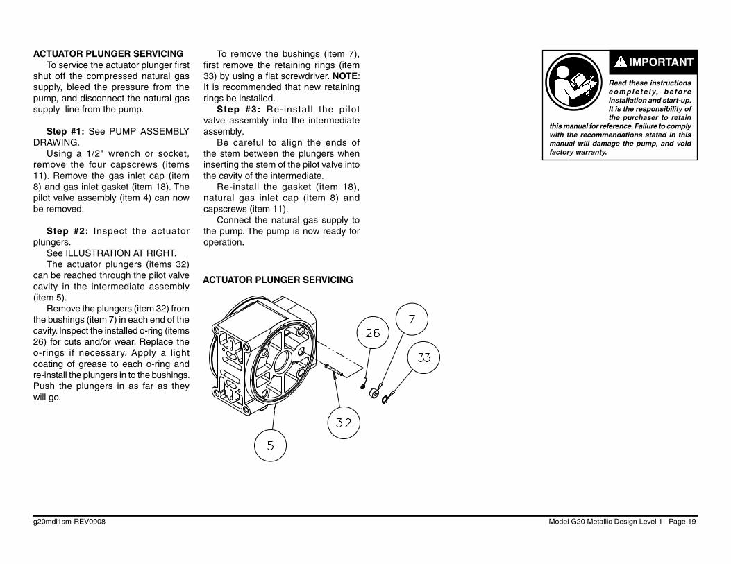
ACTUATOR PLUNGER SERVICINGTo service the actuator plunger fi rst
shut off the compressed natural gas supply, bleed the pressure from the pump, and disconnect the natural gas supply line from the pump.
Step #1: See PUMP ASSEMBLY DRAWING.
Using a 1/2" wrench or socket, remove the four capscrews (items 11). Remove the gas inlet cap (item 8) and gas inlet gasket (item 18). The pilot valve assembly (item 4) can now be removed.
Step #2: Inspect the actuator plungers.
See ILLUSTRATION AT RIGHT.The actuator plungers (items 32)
can be reached through the pilot valve cavity in the intermediate assembly (item 5).
Remove the plungers (item 32) from the bushings (item 7) in each end of the cavity. Inspect the installed o-ring (items 26) for cuts and/or wear. Replace the o-rings if necessary. Apply a light coating of grease to each o-ring and re-install the plungers in to the bushings. Push the plungers in as far as they will go.
To remove the bushings (item 7), fi rst remove the retaining rings (item 33) by using a fl at screwdriver. NOTE: It is recommended that new retaining rings be installed.
Step #3: Re-instal l the pi lot valve assembly into the intermediate assembly.
Be careful to align the ends of the stem between the plungers when inserting the stem of the pilot valve into the cavity of the intermediate.
Re-install the gasket (item 18), natural gas inlet cap (item 8) and capscrews (item 11).
Connect the natural gas supply to the pump. The pump is now ready for operation.
ACTUATOR PLUNGER SERVICING
Read these instructions c o m p l e t e ly, b e fo r e installation and start-up. It is the responsibility of the purchaser to retain
this manual for reference. Failure to comply with the recommendations stated in this manual will damage the pump, and void factory warranty.
IMPORTANT
g20mdl1sm-REV0908 Model G20 Metallic Design Level 1 Page 20
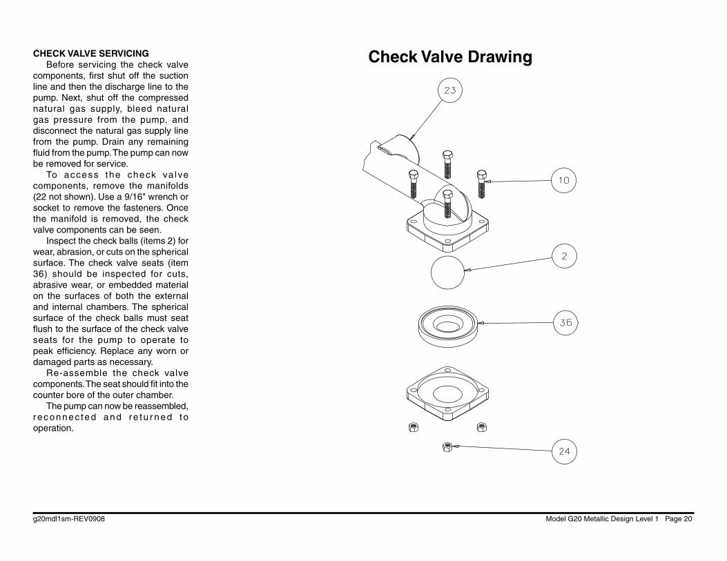
Check Valve DrawingCHECK VALVE SERVICINGBefore servicing the check valve
components, fi rst shut off the suction line and then the discharge line to the pump. Next, shut off the compressed natural gas supply, bleed natural gas pressure from the pump, and disconnect the natural gas supply line from the pump. Drain any remaining fl uid from the pump. The pump can now be removed for service.
To access the check va lve components, remove the manifolds (22 not shown). Use a 9/16" wrench or socket to remove the fasteners. Once the manifold is removed, the check valve components can be seen.
Inspect the check balls (items 2) for wear, abrasion, or cuts on the spherical surface. The check valve seats (item 36) should be inspected for cuts, abrasive wear, or embedded material on the surfaces of both the external and internal chambers. The spherical surface of the check balls must seat fl ush to the surface of the check valve seats for the pump to operate to peak effi ciency. Replace any worn or damaged parts as necessary.
Re-assemble the check valve components. The seat should fi t into the counter bore of the outer chamber.
The pump can now be reassembled, r econnec ted and re tu r ned t o operation.
g20mdl1sm-REV0908 Model G20 Metallic Design Level 1 Page 21
SAFE NATURAL GASEXHAUSTDISPOSALAREA
PUMP INSTALLATION AREA
1/2" DIAMETER NATURAL GAS EXHAUST PIPING
1/2" DIAMETER NATURAL GAS EXHAUST PIPING
1/2" DIAMETER NATURAL GAS EXHAUST PIPING
LIQUIDLEVEL
SUCTIONLINE
LIQUIDLEVEL
SUCTIONLINE
SAFE NATURAL GASEXHAUSTDISPOSALAREA
SAFE NATURAL GASEXHAUSTDISPOSALAREA
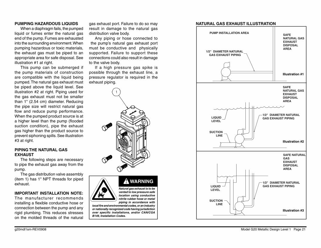
PUMPING HAZARDOUS LIQUIDSWhen a diaphragm fails, the pumped
liquid or fumes enter the natural gas end of the pump. Fumes are exhausted into the surrounding environment. When pumping hazardous or toxic materials, the exhaust gas must be piped to an appropriate area for safe disposal. See illustration #1 at right.
This pump can be submerged if the pump materials of construction are compatible with the liquid being pumped. The natural gas exhaust must be piped above the liquid level. See illustration #2 at right. Piping used for the gas exhaust must not be smaller than 1" (2.54 cm) diameter. Reducing the pipe size will restrict natural gas fl ow and reduce pump performance. When the pumped product source is at a higher level than the pump (fl ooded suction condition), pipe the exhaust gas higher than the product source to prevent siphoning spills. See illustration #3 at right.
PIPING THE NATURAL GAS EXHAUST
The following steps are necessary to pipe the exhaust gas away from the pump.
The gas distribution valve assembly (item 1) has 1" NPT threads for piped exhaust.
IMPORTANT INSTALLATION NOTE: The manufacturer recommends installing a fl exible conductive hose or connection between the pump and any rigid plumbing. This reduces stresses on the molded threads of the natural
gas exhaust port. Failure to do so may result in damage to the natural gas distribution valve body.
Any piping or hose connected to the pump’s natural gas exhaust port must be conductive and physically supported. Failure to support these connections could also result in damage to the valve body.
If a high pressure gas spike is possible through the exhaust line, a pressure regulator is required in the exhaust piping.
NATURAL GAS EXHAUST ILLUSTRATION
Illustration #1
Illustration #2
Illustration #3
Natural gas exhaust is to be vented to low pressure safe location using conductive nitrile rubber hose or metal piping in accordance with
local fi re and environmental codes, or an industry or nationally recognized code having jurisdiction over specifi c installations, and/or CAN/CGA B149, Installation Codes.
WARNING
g20mdl1sm-REV0908 Model G20 Metallic Design Level 1 Page 22
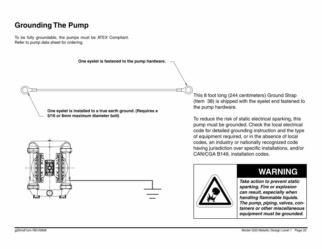
Grounding The Pump
This 8 foot long (244 centimeters) Ground Strap (Item 38) is shipped with the eyelet end fastened to the pump hardware.
To reduce the risk of static electrical sparking, this pump must be grounded. Check the local electrical code for detailed grounding instruction and the type of equipment required, or in the absence of local codes, an industry or nationally recognized code having jurisdiction over specifi c installations, and/or CAN/CGA B149, installation codes.
Take action to prevent static sparking. Fire or explosion can result, especially when handling fl ammable liquids. The pump, piping, valves, con-tainers or other miscellaneous equipment must be grounded.
WARNING
One eyelet is fastened to the pump hardware.
One eyelet is installed to a true earth ground. (Requires a 5/16 or 8mm maximum diameter bolt)
To be fully groundable, the pumps must be ATEX Compliant. Refer to pump data sheet for ordering.

Declaration of Conformity
CE
Signature of authorized person Date of issue
Printed name of authorized person Title
David Roseberry Engineering Manager
October 20, 2005
Warren Rupp, Inc., 800 North Main Street, Mansfield, Ohio, certifies that Air-Operated Double Diaphragm Pumps Series: HDB, HDF, M Non-Metallic, S Non-Metallic, M Metallic, S Metallic, Containment Duty, Gas, UL, High Pressure, W, Submersible and Tranquilizers comply with the European Community Directive 98/37/EC, Safety of Machinery. This product has used EN 809, Pumps and Pump Units for Liquids - Common Safety Requirements harmonized standard to verify conformance.