Embed Size (px)
Citation preview
CE 569 Deep Excavations & Retaining Structures Department of Civil Engineering
Middle East Technical University, Ankara, Turkey Instructor: Prof. Dr. K. Önder Çetin
Question 1
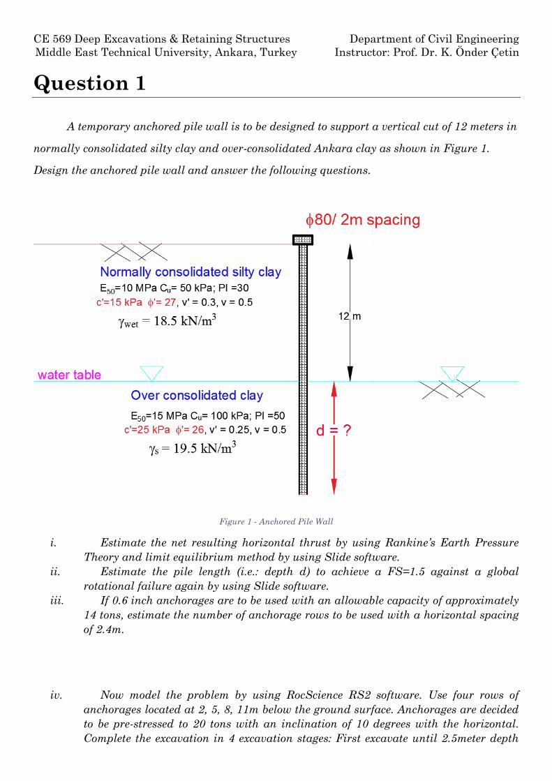
A temporary anchored pile wall is to be designed to support a vertical cut of 12 meters in
normally consolidated silty clay and over-consolidated Ankara clay as shown in Figure 1.
Design the anchored pile wall and answer the following questions.
Figure 1 - Anchored Pile Wall
i. Estimate the net resulting horizontal thrust by using Rankine’s Earth Pressure
Theory and limit equilibrium method by using Slide software.
ii. Estimate the pile length (i.e.: depth d) to achieve a FS=1.5 against a global
rotational failure again by using Slide software.
iii. If 0.6 inch anchorages are to be used with an allowable capacity of approximately
14 tons, estimate the number of anchorage rows to be used with a horizontal spacing
of 2.4m.
iv. Now model the problem by using RocScience RS2 software. Use four rows of
anchorages located at 2, 5, 8, 11m below the ground surface. Anchorages are decided
to be pre-stressed to 20 tons with an inclination of 10 degrees with the horizontal.
Complete the excavation in 4 excavation stages: First excavate until 2.5meter depth
CE 569 Deep Excavations & Retaining Structures Department of Civil Engineering
Middle East Technical University, Ankara, Turkey Instructor: Prof. Dr. K. Önder Çetin
Assignment 5: The Assessment of the Performance of Anchored Pile Walls with RocScience RS2
and then install the anchor at Level 1. Second, third and fourth stages involves the
excavation to 5.5, 8.5,12m depths and the installation of Level 2, 3 and 4 anchorages.
v. Design the anchorages (i.e.: decide about the trumpet size, # of anchor tendons,
grout length and free lengths, etc.)
vi. Estimate the factor of safety against tendon tensile failure and pull-out failure of
grout-soil bond.
vii. Draw bending moment, axial force and shear diagrams corresponding to each
excavation stage.
viii. Design the pile reinforcement against flexural, axial and shear failure. Assume a
minimum concrete cover of 7.5cm and concrete class C30.
ix. Estimate the factor of safety against base heave.
x. Discuss if estimated lateral and vertical displacement profiles behind the pile wall
is consistent with available literature. How would you improve the system if the
displacements estimated are higher than allowable?
Question 1.1
Estimate the net resulting horizontal thrust by using Rankine’s Earth Pressure Theory
and limit equilibrium method by using Slide software.
Calculation using Rankine’s Earth Pressure Theory:
1 sin 1 sin(27)0.376
1 sin 1 sin(27)aK
0
2 15 0.3762 / 2.64
0.376 18.5a a wetz c K K m
2 46.71 (12 2.64)0.376 18.5 (12 2.64) 2 15 0.376 46.71 /
2218.61 /a Xp kN m P kN m
CE 569 Deep Excavations & Retaining Structures Department of Civil Engineering
Middle East Technical University, Ankara, Turkey Instructor: Prof. Dr. K. Önder Çetin
Assignment 5: The Assessment of the Performance of Anchored Pile Walls with RocScience RS2
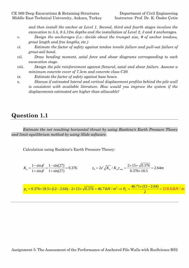
Using Slide software, back analysis is
made. Janbu Simplified limit equilibrium
method is selected and force elevation is
selected to be 3m above the base of the soil
mass.
According to the back analysis,
Px= 183.454kN/m
Question 1.2
Estimate the pile length (i.e.: depth d) to achieve a FS=1.5 against a global rotational
failure again by using Slide software.
In order to maintain overall stability of the system for the failure mode shown in Figure
2, soil profile and a pile is modelled in Slide software.
CE 569 Deep Excavations & Retaining Structures Department of Civil Engineering
Middle East Technical University, Ankara, Turkey Instructor: Prof. Dr. K. Önder Çetin
Assignment 5: The Assessment of the Performance of Anchored Pile Walls with RocScience RS2
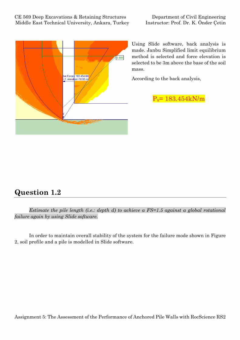
Figure 2 - Overall Instability Failure Mode(Clayton, 1986, p. 230)
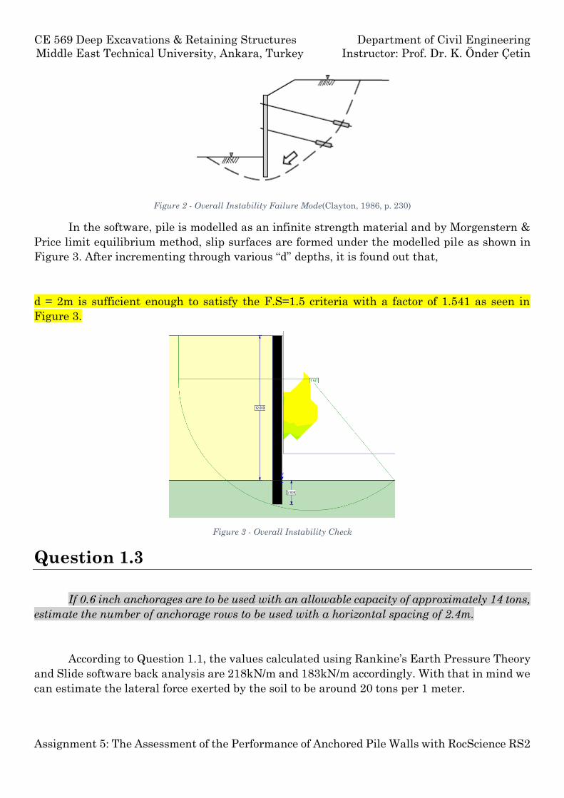
In the software, pile is modelled as an infinite strength material and by Morgenstern &
Price limit equilibrium method, slip surfaces are formed under the modelled pile as shown in
Figure 3. After incrementing through various “d” depths, it is found out that,
d = 2m is sufficient enough to satisfy the F.S=1.5 criteria with a factor of 1.541 as seen in
Figure 3.
Figure 3 - Overall Instability Check
Question 1.3
If 0.6 inch anchorages are to be used with an allowable capacity of approximately 14 tons,
estimate the number of anchorage rows to be used with a horizontal spacing of 2.4m.
According to Question 1.1, the values calculated using Rankine’s Earth Pressure Theory
and Slide software back analysis are 218kN/m and 183kN/m accordingly. With that in mind we
can estimate the lateral force exerted by the soil to be around 20 tons per 1 meter.
CE 569 Deep Excavations & Retaining Structures Department of Civil Engineering
Middle East Technical University, Ankara, Turkey Instructor: Prof. Dr. K. Önder Çetin
Assignment 5: The Assessment of the Performance of Anchored Pile Walls with RocScience RS2
Rankine Slide Estimated
218.61kN/m 183.454kN/m 20ton/m
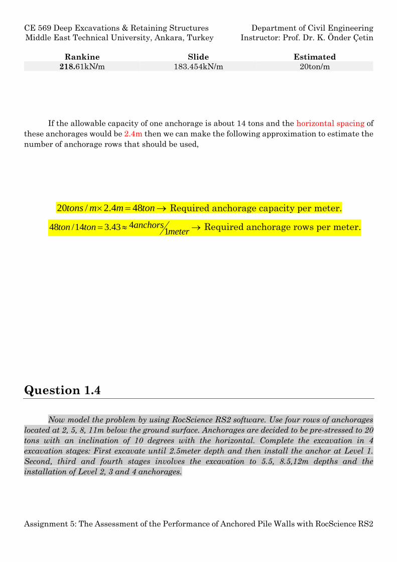
If the allowable capacity of one anchorage is about 14 tons and the horizontal spacing of
these anchorages would be 2.4m then we can make the following approximation to estimate the
number of anchorage rows that should be used,
20 / 2.4 48tons m m ton Required anchorage capacity per meter.
448 /14 3.431
anchorston tonmeter
Required anchorage rows per meter.
Question 1.4
Now model the problem by using RocScience RS2 software. Use four rows of anchorages
located at 2, 5, 8, 11m below the ground surface. Anchorages are decided to be pre-stressed to 20
tons with an inclination of 10 degrees with the horizontal. Complete the excavation in 4
excavation stages: First excavate until 2.5meter depth and then install the anchor at Level 1.
Second, third and fourth stages involves the excavation to 5.5, 8.5,12m depths and the
installation of Level 2, 3 and 4 anchorages.
CE 569 Deep Excavations & Retaining Structures Department of Civil Engineering
Middle East Technical University, Ankara, Turkey Instructor: Prof. Dr. K. Önder Çetin
Assignment 5: The Assessment of the Performance of Anchored Pile Walls with RocScience RS2
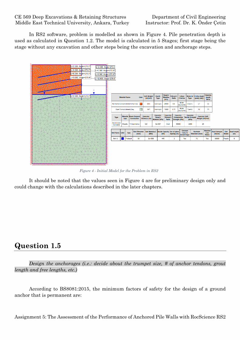
In RS2 software, problem is modelled as shown in Figure 4. Pile penetration depth is
used as calculated in Question 1.2. The model is calculated in 5 Stages; first stage being the
stage without any excavation and other steps being the excavation and anchorage steps.
It should be noted that the values seen in Figure 4 are for preliminary design only and
could change with the calculations described in the later chapters.
Question 1.5
Design the anchorages (i.e.: decide about the trumpet size, # of anchor tendons, grout
length and free lengths, etc.)
According to BS8081:2015, the minimum factors of safety for the design of a ground
anchor that is permanent are:
Figure 4 - Initial Model for the Problem in RS2
CE 569 Deep Excavations & Retaining Structures Department of Civil Engineering
Middle East Technical University, Ankara, Turkey Instructor: Prof. Dr. K. Önder Çetin
Assignment 5: The Assessment of the Performance of Anchored Pile Walls with RocScience RS2
Tendon Ground/Grout Interface Grout/Tendon Interface
2.0 3.0 3.0
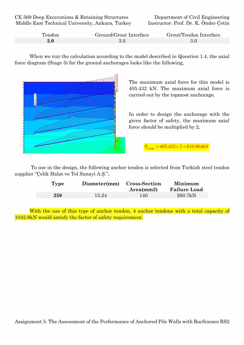
When we run the calculation according to the model described in Question 1.4, the axial
force diagram (Stage 5) for the ground anchorages looks like the following,
The maximum axial force for this model is
405.432 kN. The maximum axial force is
carried out by the topmost anchorage.
In order to design the anchorage with the
given factor of safety, the maximum axial
force should be multiplied by 2,
405.432 2 810.864designP kN
To use in the design, the following anchor tendon is selected from Turkish steel tendon
supplier “Çelik Halat ve Tel Sanayi A.Ş.”,
Type Diameter(mm) Cross-Section
Area(mm2)
Minimum
Failure Load
250 15.24 140 260.7kN
With the use of this type of anchor tendon, 4 anchor tendons with a total capacity of
1042.8kN would satisfy the factor of safety requirement.
CE 569 Deep Excavations & Retaining Structures Department of Civil Engineering
Middle East Technical University, Ankara, Turkey Instructor: Prof. Dr. K. Önder Çetin
Assignment 5: The Assessment of the Performance of Anchored Pile Walls with RocScience RS2
15,24
45
10
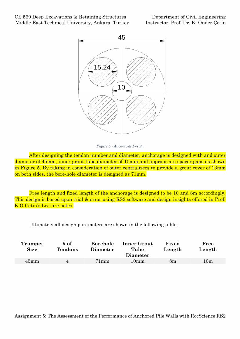
Figure 5 - Anchorage Design
After designing the tendon number and diameter, anchorage is designed with and outer
diameter of 45mm, inner grout tube diameter of 10mm and appropriate spacer gaps as shown
in Figure 5. By taking in consideration of outer centralizers to provide a grout cover of 13mm
on both sides, the bore-hole diameter is designed as 71mm.
Free length and fixed length of the anchorage is designed to be 10 and 8m accordingly.
This design is based upon trial & error using RS2 software and design insights offered in Prof.
K.O.Cetin’s Lecture notes.
Ultimately all design parameters are shown in the following table;
Trumpet
Size
# of
Tendons
Borehole
Diameter
Inner Grout
Tube
Diameter
Fixed
Length
Free
Length
45mm 4 71mm 10mm 8m 10m
CE 569 Deep Excavations & Retaining Structures Department of Civil Engineering
Middle East Technical University, Ankara, Turkey Instructor: Prof. Dr. K. Önder Çetin
Assignment 5: The Assessment of the Performance of Anchored Pile Walls with RocScience RS2
Question 1.6
Estimate the factor of safety against tendon tensile failure and pull-out failure of grout-
soil bond.
The calculated tensile force acting on one anchorage is 405.432kN and the ultimate
tensile capacity of one anchorage is 1042.8. So the following calculation is made,
1042.8. . 2.57 2 . .
405.43
kNF S O K
kN
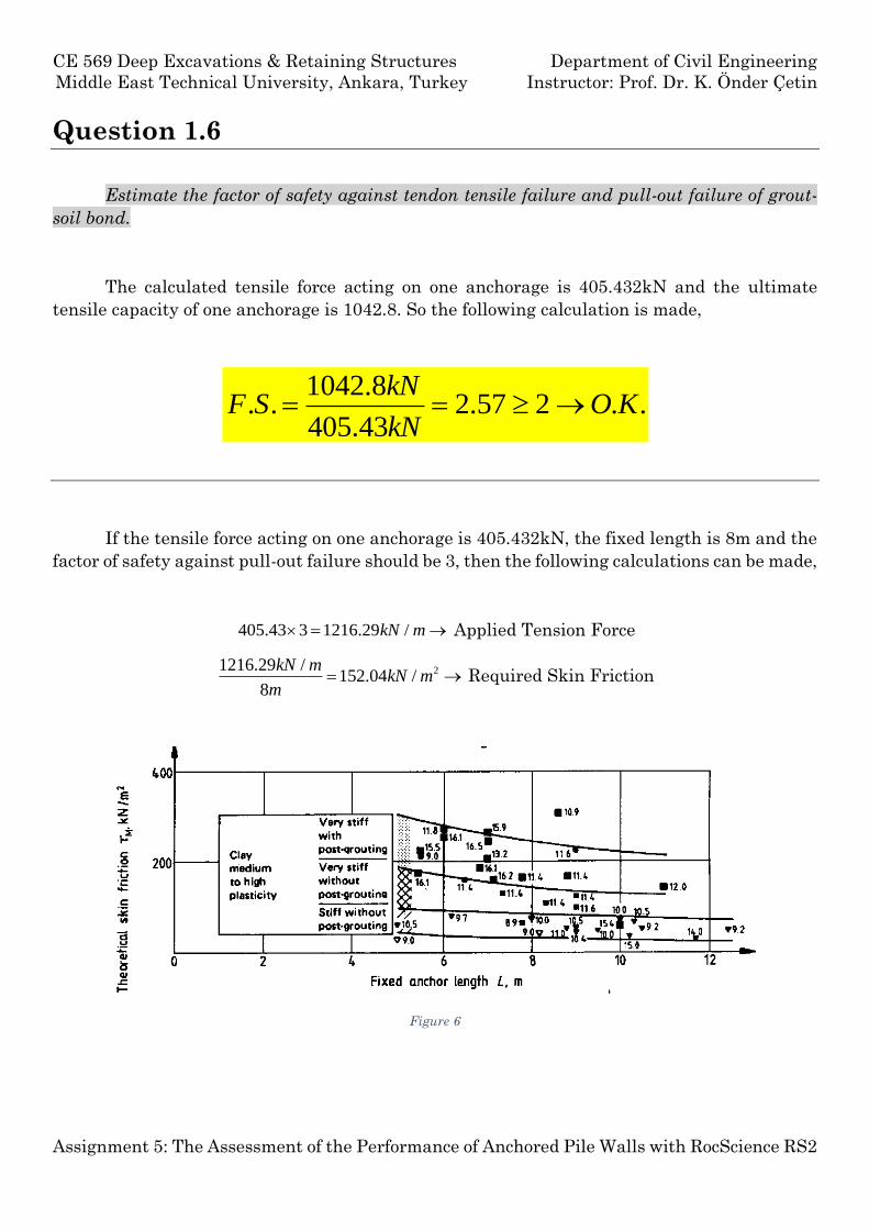
If the tensile force acting on one anchorage is 405.432kN, the fixed length is 8m and the
factor of safety against pull-out failure should be 3, then the following calculations can be made,
405.43 3 1216.29 /kN m Applied Tension Force
21216.29 /152.04 /
8
kN mkN m
m Required Skin Friction
Figure 6
CE 569 Deep Excavations & Retaining Structures Department of Civil Engineering
Middle East Technical University, Ankara, Turkey Instructor: Prof. Dr. K. Önder Çetin
Assignment 5: The Assessment of the Performance of Anchored Pile Walls with RocScience RS2
Figure 7 - Skin friction in cohesive soils for various fixed anchor lengths, with and without post-grouting(Ostermayer, 1970)
According to Figure 7 and Figure 6 expected skin friction is about ≈150kN/m2 due to
plasticity and stiffness of the normally consolidated clay soil. So we can say that the estimated
skin friction satisfies the F.S=3 criteria. On the other hand, one may use post-grouting
techniques to further increase the skin friction in order to be more conservative.
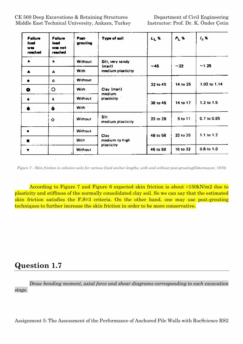
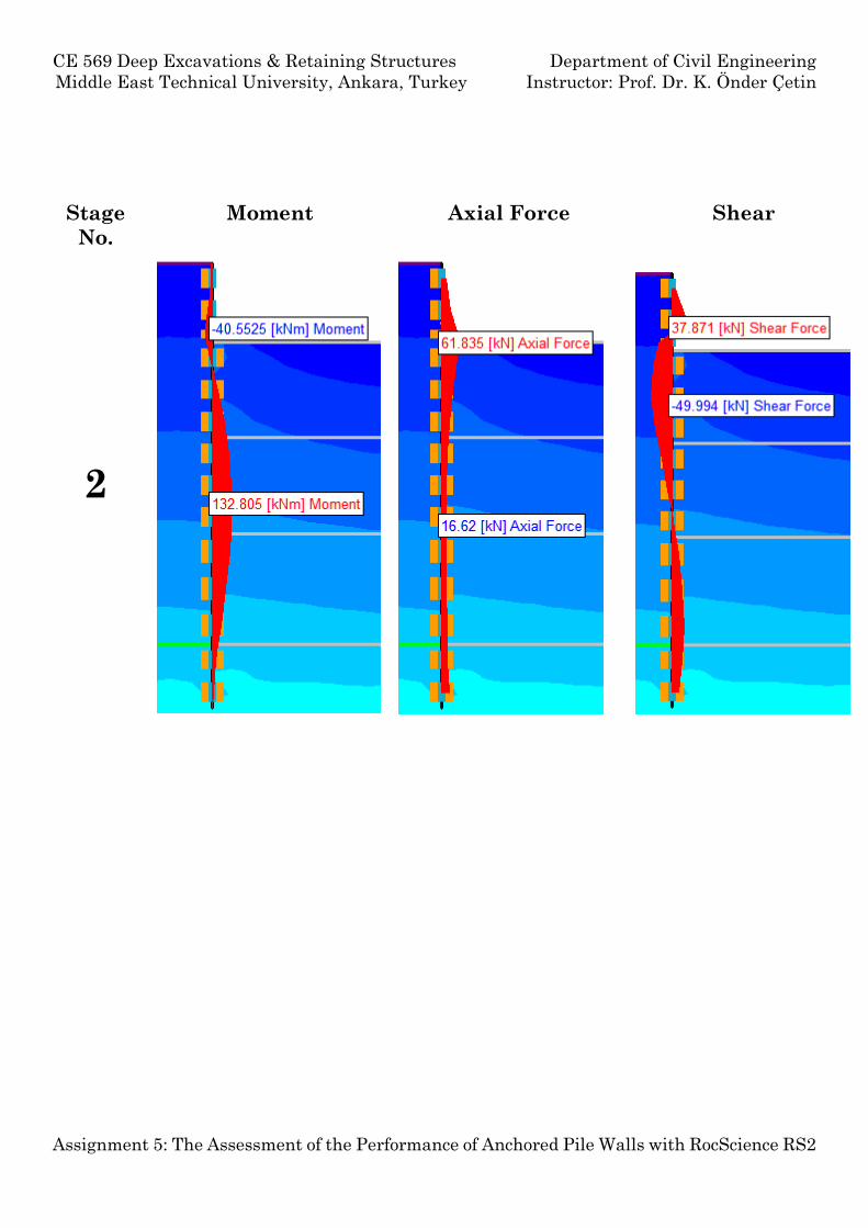
Question 1.7
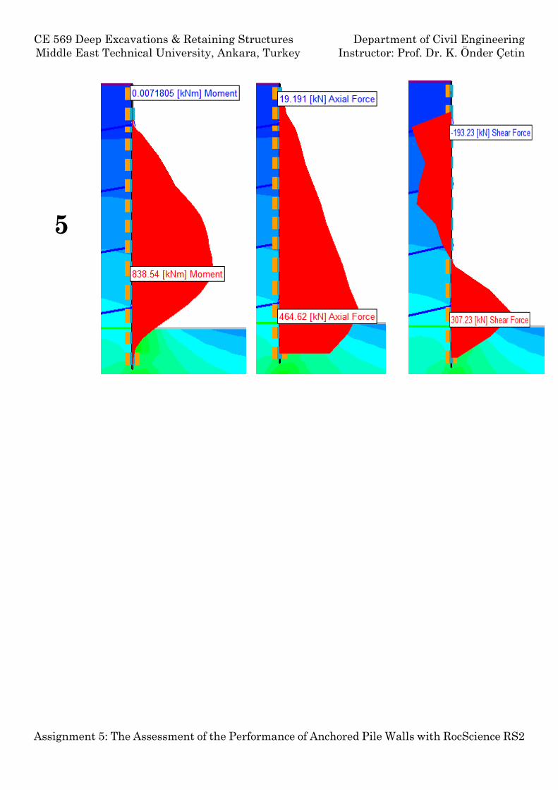
Draw bending moment, axial force and shear diagrams corresponding to each excavation
stage.
CE 569 Deep Excavations & Retaining Structures Department of Civil Engineering
Middle East Technical University, Ankara, Turkey Instructor: Prof. Dr. K. Önder Çetin
Assignment 5: The Assessment of the Performance of Anchored Pile Walls with RocScience RS2
Stage
No.
Moment Axial Force Shear
2
CE 569 Deep Excavations & Retaining Structures Department of Civil Engineering
Middle East Technical University, Ankara, Turkey Instructor: Prof. Dr. K. Önder Çetin
Assignment 5: The Assessment of the Performance of Anchored Pile Walls with RocScience RS2
3
4
CE 569 Deep Excavations & Retaining Structures Department of Civil Engineering
Middle East Technical University, Ankara, Turkey Instructor: Prof. Dr. K. Önder Çetin
Assignment 5: The Assessment of the Performance of Anchored Pile Walls with RocScience RS2
5
CE 569 Deep Excavations & Retaining Structures Department of Civil Engineering
Middle East Technical University, Ankara, Turkey Instructor: Prof. Dr. K. Önder Çetin
Assignment 5: The Assessment of the Performance of Anchored Pile Walls with RocScience RS2
Question 1.8
Design the pile reinforcement against flexural, axial and shear failure. Assume a
minimum concrete cover of 7.5cm and concrete class C30.
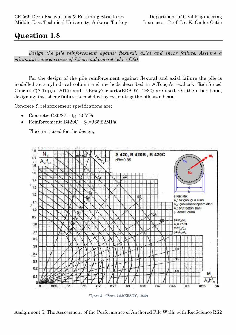
For the design of the pile reinforcement against flexural and axial failure the pile is
modelled as a cylindrical column and methods described in A.Topçu’s textbook “Reinforced
Concrete”(A.Topçu, 2015) and U.Ersoy’s charts(ERSOY, 1980) are used. On the other hand,
design against shear failure is modelled by estimating the pile as a beam.
Concrete & reinforcement specifications are;
Concrete: C30/37 – fcd=20MPa
Reinforcement: B420C – fyd=365.22MPa
The chart used for the design,
Figure 8 - Chart 8-62(ERSOY, 1980)
CE 569 Deep Excavations & Retaining Structures Department of Civil Engineering
Middle East Technical University, Ankara, Turkey Instructor: Prof. Dr. K. Önder Çetin
Assignment 5: The Assessment of the Performance of Anchored Pile Walls with RocScience RS2
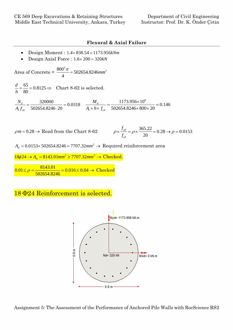
Flexural & Axial Failure
Design Moment : 1.4 838.54 1173.956kNm
Design Axial Force : 1.6 200 320kN
Area of Concrete = 2
2800502654.8246
4mm
650.8125
80
d
h Chart 8-62 is selected.
3200000.0318
502654.8246 20
d
c cd
N
A f
61173.956 100.146
502654.8246 800 20
d
c cd
M
A h f
0.28m Read from the Chart 8-62 365.22
0.28 0.015320
yd
cd
f
f
20.0153 502654.8246 7707.32stA mm Required reinforcement area
2 218 24 8143.01 7707.32stA mm mm Checked.
8143.010.01 0.016 0.04
502654.8246 Checked
18 Φ24 Reinforcement is selected.
CE 569 Deep Excavations & Retaining Structures Department of Civil Engineering
Middle East Technical University, Ankara, Turkey Instructor: Prof. Dr. K. Önder Çetin
Assignment 5: The Assessment of the Performance of Anchored Pile Walls with RocScience RS2
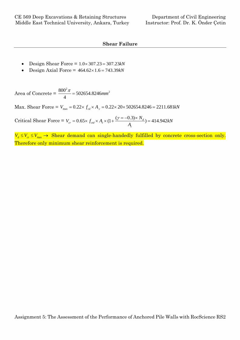
Shear Failure
Design Shear Force = 1.0 307.23 307.23kN
Design Axial Force = 464.62 1.6 743.39kN
Area of Concrete = 2
2800502654.8246
4mm
Max. Shear Force = max 0.22 0.22 20 502654.8246 2211.681cd cV f A kN
Critical Shear Force = ( 0.3)
0.65 (1 ) 414.942dcr ctd c
c
NV f A kN
A
maxd crV V V Shear demand can single-handedly fulfilled by concrete cross-section only.
Therefore only minimum shear reinforcement is required.
CE 569 Deep Excavations & Retaining Structures Department of Civil Engineering
Middle East Technical University, Ankara, Turkey Instructor: Prof. Dr. K. Önder Çetin
Assignment 5: The Assessment of the Performance of Anchored Pile Walls with RocScience RS2
Question 1.9
Estimate the factor of safety against base heave.
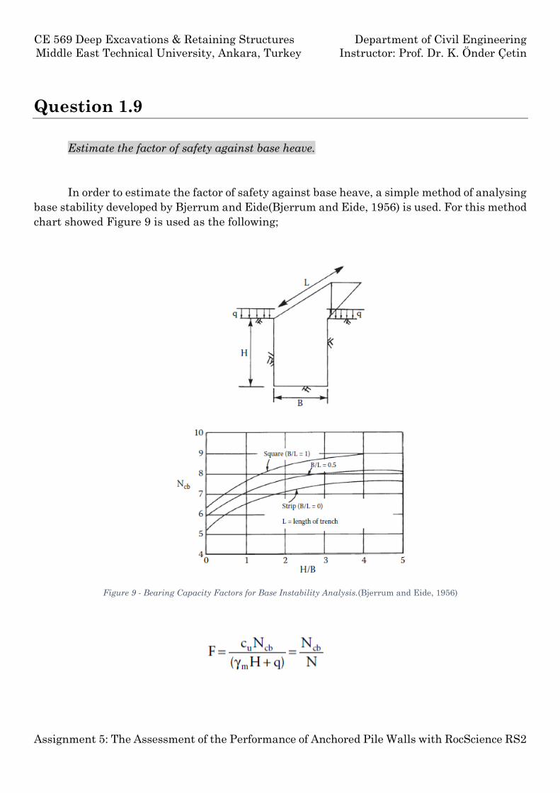
In order to estimate the factor of safety against base heave, a simple method of analysing
base stability developed by Bjerrum and Eide(Bjerrum and Eide, 1956) is used. For this method
chart showed Figure 9 is used as the following;
Figure 9 - Bearing Capacity Factors for Base Instability Analysis.(Bjerrum and Eide, 1956)
CE 569 Deep Excavations & Retaining Structures Department of Civil Engineering
Middle East Technical University, Ankara, Turkey Instructor: Prof. Dr. K. Önder Çetin
Assignment 5: The Assessment of the Performance of Anchored Pile Walls with RocScience RS2
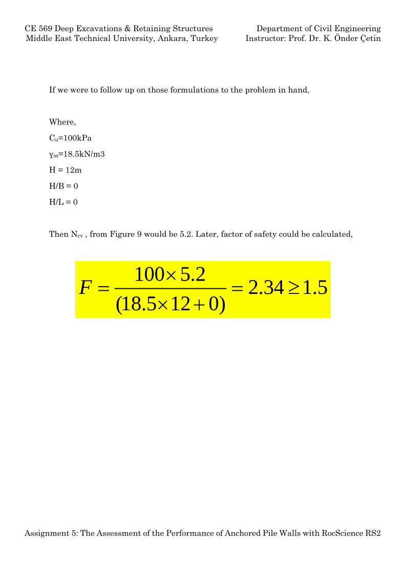
If we were to follow up on those formulations to the problem in hand,
Where,
Cu=100kPa
γm=18.5kN/m3
H = 12m
H/B = 0
H/L = 0
Then Ncv , from Figure 9 would be 5.2. Later, factor of safety could be calculated,
100 5.22.34 1.5
(18.5 12 0)F
CE 569 Deep Excavations & Retaining Structures Department of Civil Engineering
Middle East Technical University, Ankara, Turkey Instructor: Prof. Dr. K. Önder Çetin
Assignment 5: The Assessment of the Performance of Anchored Pile Walls with RocScience RS2
Question 1.10
Discuss if estimated lateral and vertical displacement profiles behind the pile wall is
consistent with available literature. How would you improve the system if the displacements
estimated are higher than allowable?
If the displacements estimated are higher than allowable, the most effective way to improve
displacements is to increase the pre-stress value of the anchorages.
Additional anchorage installation or increase in pile diameter ( which will increase the rigidity
of the wall ) would improve the displacements.
References
A.Topçu (2015) Reinforced Concrete.
Bjerrum, L. and Eide, O. (1956) ‘Stability of strutted excavations in clay.’, Geotechnique, 6(1),
pp. 32–47.
Clayton, C. R. I. (1986) Earth Pressure and Earth-Retaining Structures. Available at:
http://eprints.soton.ac.uk/74981/.
ERSOY, U. (1980) Taşıma Gücü El Kitabı. Ankara.
Ostermayer, H. (1970) ‘Construction, carrying behaviour and creep characteristics of ground
anchors’, Ground Engineering, 33, p. 44.