Embed Size (px)
Citation preview
CE 150 1
CE 150Fluid Mechanics
G.A. Kallio
Dept. of Mechanical Engineering, Mechatronic Engineering & Manufacturing Technology
California State University, Chico
CE 150 2
Elementary Fluid Dynamics
Reading: Munson, et al., Chapter 3

CE 150 3
Inviscid Flow
• In this chapter we consider “ideal” fluid motion known as inviscid flow; this type of flow occurs when either
1) 0 (only valid for He near 0 K), or
2) viscous shearing stresses are negligible
• The inviscid flow assumption is often valid in regions removed from solid surfaces; it can be applied to many problems involving flow through pipes and flow over aerodynamic shapes
CE 150 4
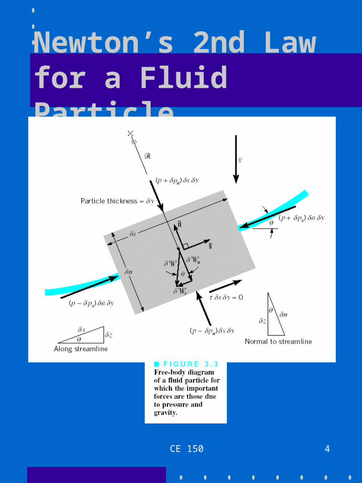
Newton’s 2nd Law for a Fluid Particle

CE 150 5
Newton’s 2nd Law for a Fluid Particle• The equation of motion for a fluid
particle in a steady inviscid flow:
• We consider force components in two directions: along a streamline (s) and normal to a streamline (n):
gp
extgp
FFdt
Vdm
FFFFam
cos
sin
2
WFV
m
WFds
dVmV
pn
ps

CE 150 6
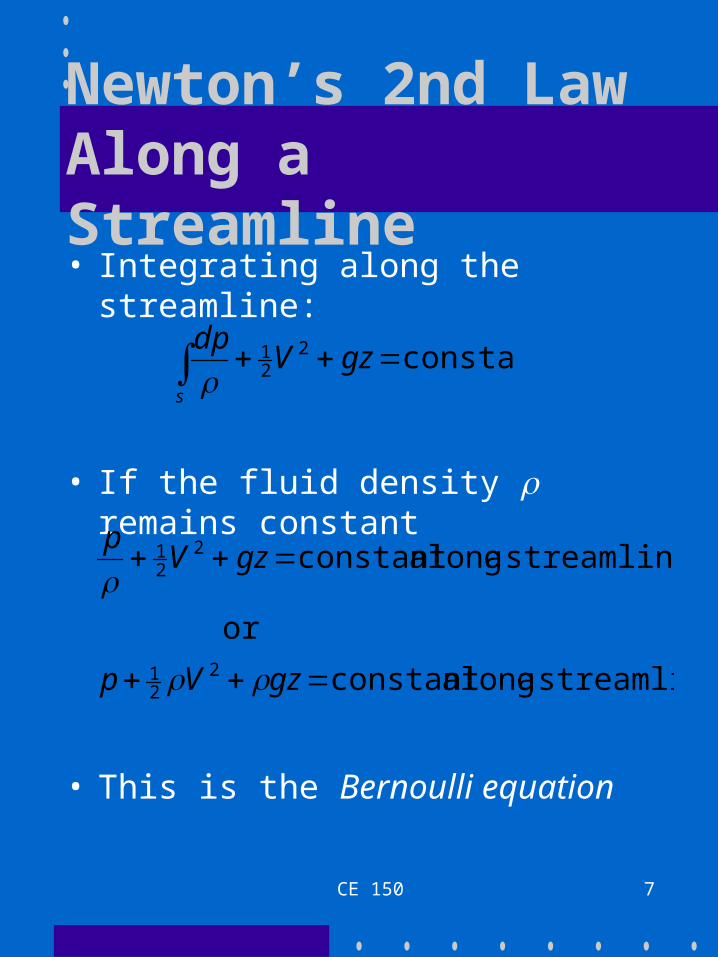
Newton’s 2nd Law Along a Streamline
• Noting that
we have:
, and
,sin ,
Vds
dpF
ds
dzVgWVm
ps
ds
dp
ds
dzg
ds
dVV
CE 150 7
Newton’s 2nd Law Along a Streamline• Integrating along the streamline:
• If the fluid density remains constant
• This is the Bernoulli equation
constant221 gzV
dp
s
streamlinea alongconstant
or
streamlinea alongconstant
221
221
gzVp
gzVp

CE 150 8
Newton’s 2nd Law Across a Streamline
• A similar analysis applied normal to the streamline for a fluid of constant density yields
• This equation is not as useful as the Bernoulli equation because the radius of curvature of the streamline is seldom known
constant 2
gzdnV
pn
)(

CE 150 9
Physical Interpretation of the Bernoulli Equation
• Acceleration of a fluid particle is due to an imbalance of pressure forces and fluid weight
• Conservation equation involving three energy processes:– kinetic energy
– potential energy
– pressure work
streamlinea alongconstant 221 gzVp

CE 150 10
Alternate Form of the Bernoulli Equation
• Pressure head (p/g) - height of fluid column needed to produce a pressure p
• Velocity head (V2/2g) - vertical distance required for fluid to fall from rest and reach velocity V
• Elevation head (z) - actual elevation of the fluid w.r.t. a datum
streamlinea alongconstant 2
2
zg
V
g
p

CE 150 11
Bernoulli Equation Restrictions
• The following restrictions apply to the use of the (simple) Bernoulli equation:1) fluid flow must be inviscid
2) fluid flow must be steady (i.e., flow properties are not f(t) at a given location)
3) fluid density must be constant
4) equation must be applied along a streamline (unless flow is irrotational)
5) no energy sources or sinks may exist along streamline (e.g., pumps, turbines, compressors, fans, etc.)
CE 150 12
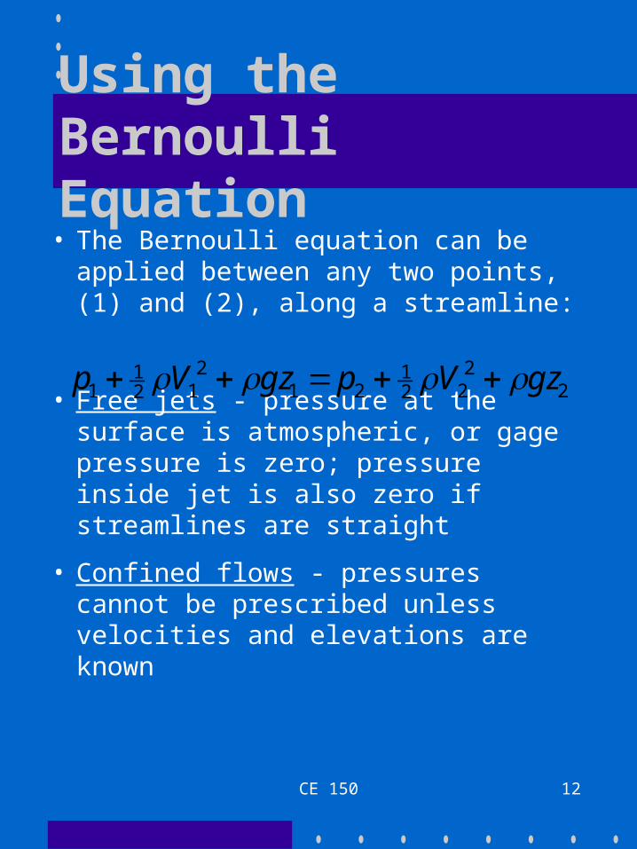
Using the Bernoulli Equation• The Bernoulli equation can be
applied between any two points, (1) and (2), along a streamline:
• Free jets - pressure at the surface is atmospheric, or gage pressure is zero; pressure inside jet is also zero if streamlines are straight
• Confined flows - pressures cannot be prescribed unless velocities and elevations are known
22
221
212
121
1 gzVpgzVp

CE 150 13
Mass and Volumetric Flow Rates• Mass flow rate: fluid mass
conveyed per unit time [kg/s]
where Vn = velocity normal to area [m/s]
= fluid density [kg/m3]
A = cross-sectional area [m2]
– if is uniform over the area A and the average velocity V is used, then
• Volumetric flow rate [m3/s]:
A ndAVm
AVm
AVQ
CE 150 14
Conservation of Mass
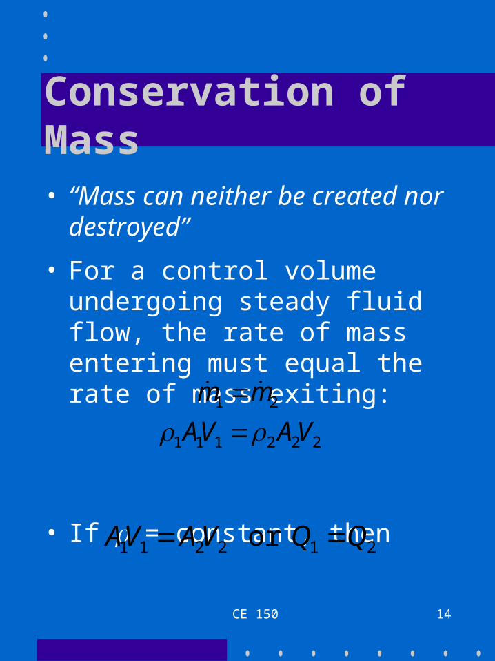
• “Mass can neither be created nor destroyed”
• For a control volume undergoing steady fluid flow, the rate of mass entering must equal the rate of mass exiting:
• If = constant, then
222111
21
VAVA
mm
212211 or QQVAVA

CE 150 15
The Bernoulli Equation in Terms of Pressure
• Each term of the Bernoulli equation can be written to represent a pressure:
• pgh : this is known as the hydrostatic pressure; while not a real pressure, it represents the possible pressure in the fluid due to changes in elevation
)(constant 221
TpgzVp
CE 150 16
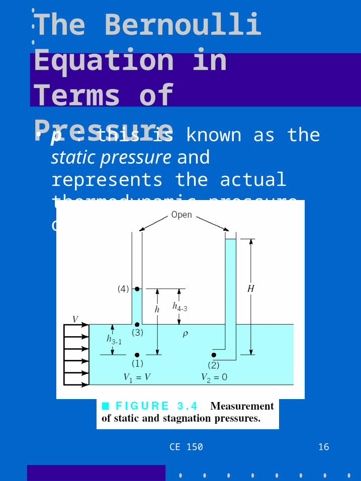
The Bernoulli Equation in Terms of Pressure• p : this is known as the static
pressure and represents the actual thermodynamic pressure of the fluid

CE 150 17
The Bernoulli Equation in Terms of Pressure
• The static pressure at (1) in Figure 3.4 can be measured from the liquid level in the open tube as pgh
• : this is known as the dynamic pressure; it is the pressure measured by the fluid level (pgH) in the stagnation tube shown in Figure 3.4 minus the static pressure; thus, it is the pressure due to the fluid velocity
221 V

CE 150 18
The Bernoulli Equation in Terms of Pressure
• The stagnation pressure is the sum of the static and dynamic pressures:
– the stagnation pressure exists at a stagnation point, where a fluid streamline abruptly terminates at the surface of a stationary body; here, the velocity of the fluid must be zero
• Total pressure (pT) is the sum of the static, dynamic, and hydrostatic pressures
212
112 Vpp

CE 150 19
Velocity and Flow Measurement• Pitot-static tube - utilizes the static
and stagnation pressures to measure the velocity of a fluid flow (usually gases):
/)(2 43 ppV

CE 150 20
Velocity and Flow Measurement• Orifice, Nozzle, and Venturi meters -
restriction devices that allow measurement of flow rate in pipes:
CE 150 21
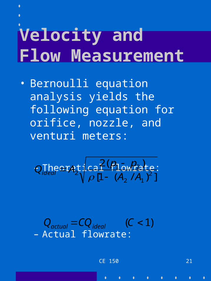
Velocity and Flow Measurement
• Bernoulli equation analysis yields the following equation for orifice, nozzle, and venturi meters:
– Theoretical flowrate:
– Actual flowrate:
])/(1[
)(22
12
212 AA
ppAQideal
)1( CCQQ idealactual

CE 150 22
Velocity and Flow Measurement
• Sluice gates and weirs - restriction devices that allow flow rate measurement of open-channel flows:
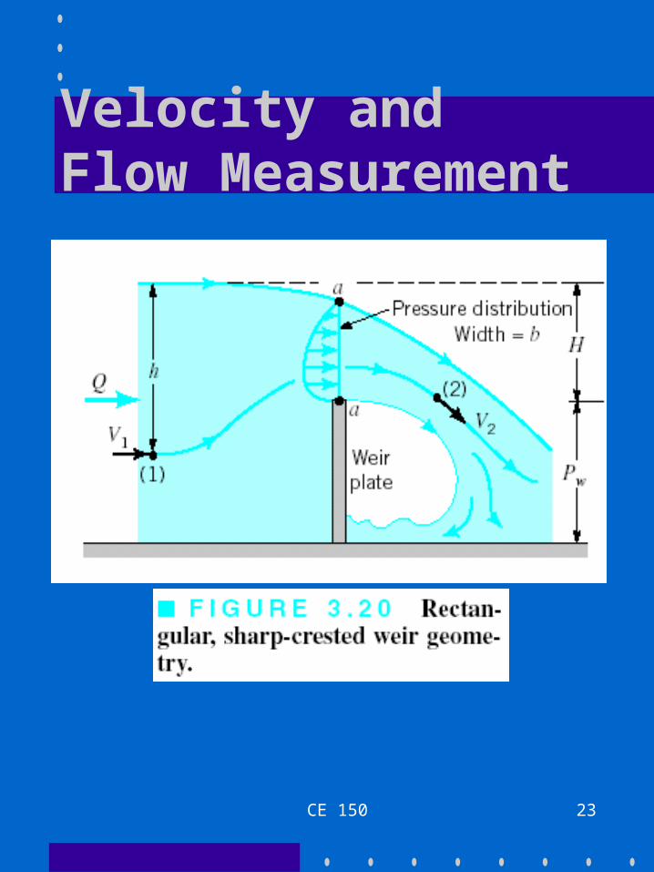
CE 150 23
Velocity and Flow Measurement