Embed Size (px)
Citation preview
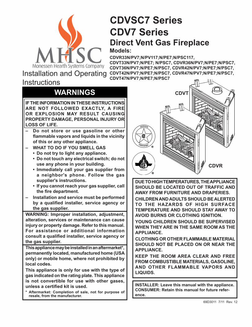
Models: CDVR33n/pV7;n/pV117;n/pe7;n/pSC117, CDVT33n/pV7;n/pe7; n/pSC7, CDVR36n/pV7;n/pe7;n/pSC7, CDVT36n/pV7;n/pe7;n/pSC7, CDVR42n/pV7;n/pe7;n/pSC7, CDVT42n/pV7;n/pe7;n/pSC7, CDVR47n/pV7;n/pe7;n/pSC7, CDVT47n/pV7;n/pe7;n/pSC7
CDVSC7 SeriesCDV7 SeriesDirect Vent Gas Fireplace
IF The InFoRMaTIon In TheSe InSTRuCTIonS aRe noT FolloweD exaCTly, a FIRe oR exploSIon May ReSulT CauSInG pRopeRTy DaMaGe, peRSonal InjuRy oR loSS oF lIFe.– Do not store or use gasoline or other
flammable vapors and liquids in the vicinity of this or any other appliance.
– whaT To Do IF you SMell GaS • Do not try to light any appliance. • Do not touch any electrical switch; do not
use any phone in your building. • Immediately call your gas supplier from
a neighbor's phone. Follow the gas supplier's instructions.
• If you cannot reach your gas supplier, call the fire department.
– Installation and service must be performed by a qualified installer, service agency or the gas supplier.
waRnInG: Improper installation, adjustment, alteration, services or maintenance can cause injury or property damage. Refer to this manual. For assistance or additional information consult a qualified installer, service agency or the gas supplier. This appliance may be installed in an aftermarket*, permanently located, manufactured home (uSa only) or mobile home, where not prohibited by local codes.This appliance is only for use with the type of gas indicated on the rating plate. This appliance is not convertible for use with other gases, unless a certified kit is used. * aftermarket: Completion of sale, not for purpose of
resale, from the manufacturer.
Due To hIGh TeMpeRaTuReS, The applIanCe ShoulD Be loCaTeD ouT oF TRaFFIC anD away FRoM FuRnITuRe anD DRapeRIeS.ChIlDRen anD aDulTS ShoulD Be aleRTeD To The haZaRDS oF hIGh SuRFaCe TeMpeRaTuRe anD ShoulD STay away To aVoID BuRnS oR CloThInG IGnITIon.younG ChIlDRen ShoulD Be SupeRVISeD when They aRe In The SaMe RooM aS The applIanCe.CloThInG oR oTheR FlaMMaBle MaTeRIal ShoulD noT Be plaCeD on oR neaR The applIanCe.Keep The RooM aRea CleaR anD FRee FRoM CoMBuSTIBle MaTeRIalS, GaSolIne, anD oTheR FlaMMaBle VapoRS anD lIquIDS.
69D3011 7/11 Rev. 12
Installation and Operating Instructions
InSTalleR: leave this manual with the appliance.ConSuMeR: Retain this manual for future refer-ence.
waRnInGS
693011CDVRT7 cover
CDVT
CDVR
CDVSC7 & CDV7 Series Gas Fireplace
2 69D3011
ConTenTS
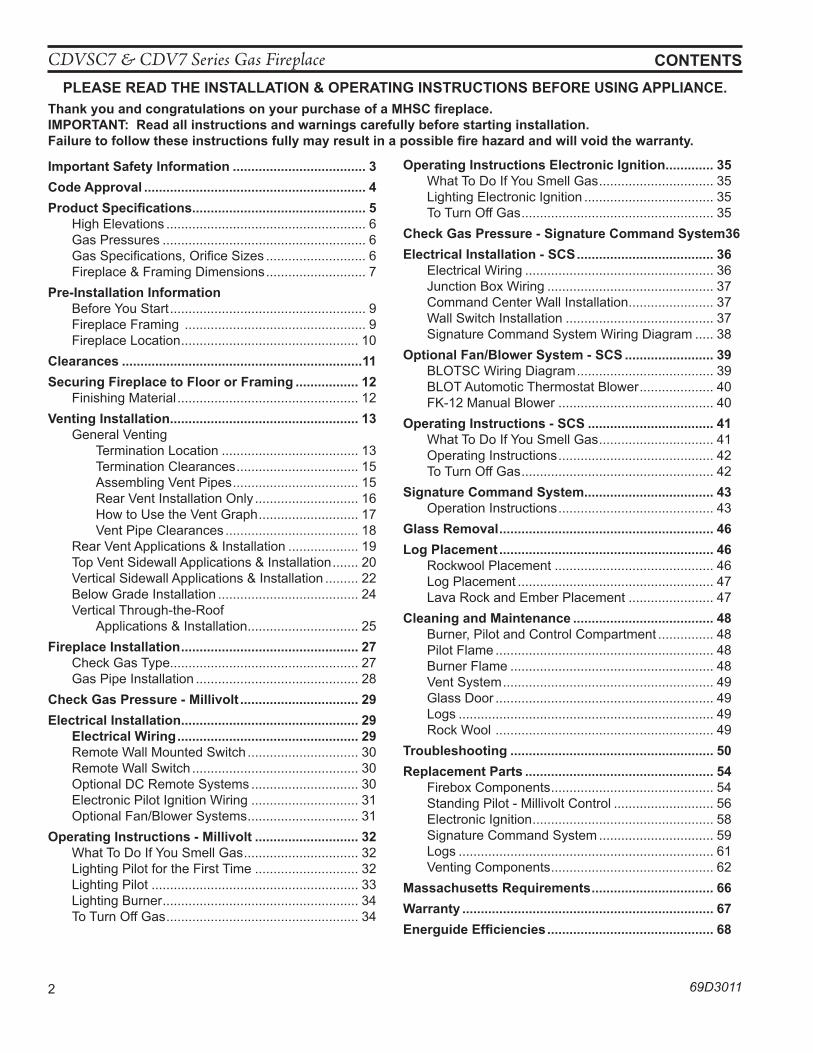
Important Safety Information .................................... 3Code approval ............................................................ 4product Specifications............................................... 5 High Elevations ...................................................... 6 Gas Pressures ....................................................... 6 Gas Specifications, Orifice Sizes ........................... 6 Fireplace & Framing Dimensions ........................... 7pre-Installation Information
Before You Start ..................................................... 9 Fireplace Framing ................................................. 9 Fireplace Location ................................................ 10
Clearances .................................................................11Securing Fireplace to Floor or Framing ................. 12 Finishing Material ................................................. 12Venting Installation ................................................... 13 General Venting Termination Location ..................................... 13 Termination Clearances ................................. 15 Assembling Vent Pipes .................................. 15 Rear Vent Installation Only ............................ 16 How to Use the Vent Graph ........................... 17 Vent Pipe Clearances .................................... 18
Rear Vent Applications & Installation ................... 19 Top Vent Sidewall Applications & Installation ....... 20
Vertical Sidewall Applications & Installation ......... 22 Below Grade Installation ...................................... 24 Vertical Through-the-Roof
Applications & Installation .............................. 25Fireplace Installation ................................................ 27
Check Gas Type................................................... 27 Gas Pipe Installation ............................................ 28
Check Gas pressure - Millivolt ................................ 29electrical Installation................................................ 29 electrical wiring ................................................. 29
Remote Wall Mounted Switch .............................. 30 Remote Wall Switch ............................................. 30 Optional DC Remote Systems ............................. 30 Electronic Pilot Ignition Wiring ............................. 31
Optional Fan/Blower Systems .............................. 31operating Instructions - Millivolt ............................ 32
What To Do If You Smell Gas ............................... 32 Lighting Pilot for the First Time ............................ 32 Lighting Pilot ........................................................ 33 Lighting Burner ..................................................... 34 To Turn Off Gas .................................................... 34
operating Instructions electronic Ignition ............. 35 What To Do If You Smell Gas ............................... 35 Lighting Electronic Ignition ................................... 35 To Turn Off Gas .................................................... 35
Check Gas pressure - Signature Command System 36electrical Installation - SCS ..................................... 36 Electrical Wiring ................................................... 36 Junction Box Wiring ............................................. 37 Command Center Wall Installation ....................... 37 Wall Switch Installation ........................................ 37 Signature Command System Wiring Diagram ..... 38optional Fan/Blower System - SCS ........................ 39 BLOTSC Wiring Diagram ..................................... 39 BLOT Automotic Thermostat Blower .................... 40 FK-12 Manual Blower .......................................... 40operating Instructions - SCS .................................. 41 What To Do If You Smell Gas ............................... 41 Operating Instructions .......................................... 42 To Turn Off Gas .................................................... 42Signature Command System................................... 43 Operation Instructions .......................................... 43Glass Removal .......................................................... 46log placement .......................................................... 46
Rockwool Placement ........................................... 46 Log Placement ..................................................... 47 Lava Rock and Ember Placement ....................... 47
Cleaning and Maintenance ...................................... 48 Burner, Pilot and Control Compartment ............... 48 Pilot Flame ........................................................... 48 Burner Flame ....................................................... 48 Vent System ......................................................... 49 Glass Door ........................................................... 49 Logs ..................................................................... 49 Rock Wool ........................................................... 49
Troubleshooting ....................................................... 50Replacement parts ................................................... 54
Firebox Components ............................................ 54 Standing Pilot - Millivolt Control ........................... 56 Electronic Ignition ................................................. 58
Signature Command System ............................... 59 Logs ..................................................................... 61 Venting Components ............................................ 62
Massachusetts Requirements ................................. 66warranty .................................................................... 67energuide efficiencies ............................................. 68
pleaSe ReaD The InSTallaTIon & opeRaTInG InSTRuCTIonS BeFoRe uSInG applIanCe.Thank you and congratulations on your purchase of a MhSC fireplace.IMpoRTanT: Read all instructions and warnings carefully before starting installation. Failure to follow these instructions fully may result in a possible fire hazard and will void the warranty.
CDVSC7 & CDV7 Series Gas Fireplace
69D3011 3
4. Never install the fireplace • in a recreational vehicle• where curtains, furniture, clothing, or other flam-
mable objects are less than 42" from the front, top, or sides of the fireplace
• in high traffic areas• in windy or drafty areas
5. This fireplace reaches high temperatures. Keep children and adults away from hot surfaces to avoid burns or clothing ignition. Fireplace will remain hot for a time after shutdown. Allow surfaces to cool before touching.
6. Young children should be carefully supervised when they are in the same room as the appliance. Toddlers, young children and others may be susceptible to acci-dental contact burns. A physical barrier is recommended if there are at risk individuals in the house. To restrict access to a fireplace or stove, install an adjustable safety gate to keep toddlers, young children and other at risk individuals out of the room and away from hot surfaces.
7. Do not modify fireplace under any circumstances. Any parts removed for servicing must be replaced prior to operating fireplace.
8. Turn fireplace off and let cool before servicing, install-ing, or repairing. Only a qualified service person should install, service, or repair the fireplace. Have burner system inspected annually by a qualified service person.
9. You must keep control compartments, burners, and circulating air passages clean. More frequent cleaning may be needed due to excessive lint and dust. Turn off the gas valve and pilot light before cleaning fireplace.
10. Have venting system inspected annually by a quali-fied service person. If needed, have venting system cleaned or repaired. See Cleaning and Maintenance, Page 48.
11. Keep the area around your fireplace clear of combus-tible materials, gasoline, and other flammable vapor and liquids. Do not run fireplace where these are used or stored. Do not place items such as clothing or decora-tions on or around fireplace.
IMpoRTanT SaFeTy InFoRMaTIon
This fireplace is a vented product. This fireplace must be properly installed by a qualified service person. The glass door must be properly seated and sealed. If this unit is not properly installed by a qualified service person with glass door properly seated and sealed, combustion leakage can occur. CaRBon MonoxIDe poISonInG: Early signs of carbon monoxide poisoning are similar to the flu with headaches, dizziness and/or nausea. If you have these signs, the fireplace may not have been installed properly. Get fresh air at once! Have the fireplace inspected and serviced by a qualified service person. Some people are more affected by carbon monoxide than others. These include pregnant women, people with heart or lung dis-ease or anemia, those under the influence of alcohol, and those at high altitudes. Propane/LP gas and natural gas are both odorless. An odor-making agent is added to each of these gases. The odor helps you detect a gas leak. However, the odor added to these gases can fade. Gas may be present even though no odor exists.Make certain you read and understand all warnings. Keep this manual for reference. It is your guide to safe and proper operation of this fireplace.1. This appliance is only for use with the type of gas
indicated on the rating plate. This appliance is not convertible for use with other gases unless a certified kit is used.
2. For propane/LP fireplace, do not place propane/LP supply tank(s) inside any structure. Locate propane/LP supply tank(s) outdoors. To prevent performance problems, do not use propane/LP fuel tank of less than 100 lbs. capacity.
3. If you smell gas• shut off gas supply.• do not try to light any appliance.• do not touch any electrical switch; do not use any
phone in your building .• immediately call your gas supplier from a neigh-
bor’s phone. Follow the gas supplier’s instruc-tions.
Continued on page 4
InSTalleRPlease leave these instructions with the appliance.
owneRPlease retain these instructions for future reference.
• Read this owner’s manual carefully and completely before trying to assemble, operate, or service this fireplace.
• any change to this fireplace or its controls can be dangerous.• Improper installation or use of this fireplace can cause serious injury or death from
fire, burns, explosions, electrical shock and carbon monoxide poisoning.wa
Rn
InG
CDVSC7 & CDV7 Series Gas Fireplace
4 69D3011
IMpoRTanT SaFeTy InFoRMaTIon
12. Do not use this fireplace to cook food or burn paper or other objects.
13. Never place anything on top of fireplace.14. Do not use any solid fuels (wood, coal, paper, card-
board, etc.) in this fireplace. Use only the gas type indicated on rating plate.
15. This appliance, when installed, must be electrically grounded in accordance with local codes or in the absence of local codes, with the National Electrical Code, ANSI/NFPA 70, or the Canadian Electrical Code, CSA C22.1.
16. Do not obstruct the flow of combustion and ventilation air in any way. Provide adequate clearances around air openings into the combustion chamber along with adequate accessibility clearance for servicing and proper operation.
17. When the appliance is installed directly on carpeting, tile or other combustible material other than wood flooring, you must set appliance on a metal or wood panel or hearth pad extending the full width and depth of the appliance.
18. Do not use fireplace if any part has been exposed to or has been under water. Immediately call a quali-fied service person to arrange for replacement of the unit.
19. Do not operate fireplace if any log is broken.20. Do not use a blower insert, heat exchanger insert, or
any other accessory not approved for use with this fireplace.
21. Do not operate the fireplace with glass door removed, cracked, or broken.
CoDe appRoVal Direct Vent type appliances draw all combustion air from outside of the dwelling through the vent pipe.These appliances have been tested by CSA and found to comply with the established standards in the USA and Canada as follows:
lISTeD VenTeD GaS FIReplaCe heaTeRTESTED TO (latest edition):
CDVR: ANSI Z21.88 / CSA 2.33 STANDARDSlISTeD VenTeD GaS FIReplaCe
CDVT: ANSI Z21.50 CSA 2.22 STANDARDSA manufactured home (USA only) or mobile home OEM installation must conform with the Manufactured home Construction and Safety Standard, Title 24 CFR, part 3280, or when such a standard is not applicable, the Standard for Manufactured home Installations, anSI/nCSBCS a225.1, or Standard for Gas equipped Recre-ational Vehicles and Mobile housing, CSa Z240.4.
IMpoRTanT:
pleaSe ReaD The FollowInG CaReFully It is normal for fireplaces fabricated of steel to give off some expansion and/or contraction noises during the start up or cool down cycle. Similar noises are found with your furnace heat exchanger or car engine.
IMpoRTanT:
pleaSe ReaD The FollowInG CaReFully It is not unusual for gas fireplace to give off some odor the first time it is burned. This is due to the manufacturing process.
please ensure that your room is well ventilated during burn off — open all
windows.It is recommended that you burn your fireplace for at least ten (10) hours the first time you use it. Place the fan switch in the “OFF” position during this time.
Nous recommandons que nos appareils de chauffage au gaz soient installés et entretenus par des professionnels qui ont été accrédités aux È.U. par le National Fireplace Institute ® (NFI) comme étant des spécialistes du NFI en matièred’appareils de chauffage au gaz.
wa
Rn
InG never connect unit to private (non-utility)
gas wells. This gas is commonly known as wellhead gas.
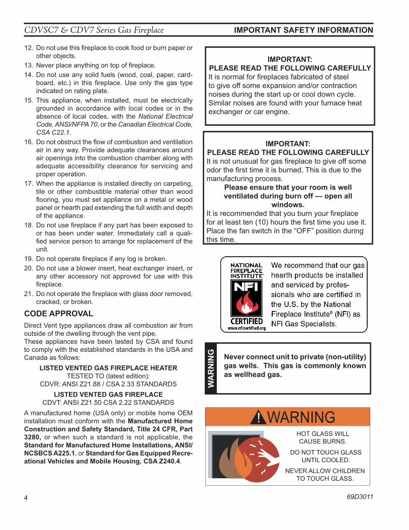
WARNING!HOT GLASS WILLCAUSE BURNS.
DO NOT TOUCH GLASSUNTIL COOLED.
NEVER ALLOW CHILDRENTO TOUCH GLASS.
AVERTISSEMENT!Un panneau vitré chaud peut
causer des brûlures.Laissez refroidir le panneau
vitré avant d’y toucher.Ne laisser jamais les enfants
toucher le panneau vitré.
CDVSC7 & CDV7 Series Gas Fireplace
69D3011 5
pRoDuCT FeaTuReS
pRoDuCT SpeCIFICaTIonS
• This appliance has been certified for use with either natural or propane gas. See appropriate data plates.
• This appliance is not for use with solid fuels.• The appliance is approved for bedroom or bedsitting
room installations.• The appliance must be installed in accordance with local
codes if any. If none exist use the current installation code. ANSI Z223.1/NFPA 54 in the USA, CSA B149 in Canada.
• This appliance is mobile home approved.• The appliance must be properly connected to a venting
system.• The appliance is not approved for closet installations.• This appliance is approved to be vented with Simpson-
Duravent and MHSC Twist-Lock Direct Vent Compo-nents.
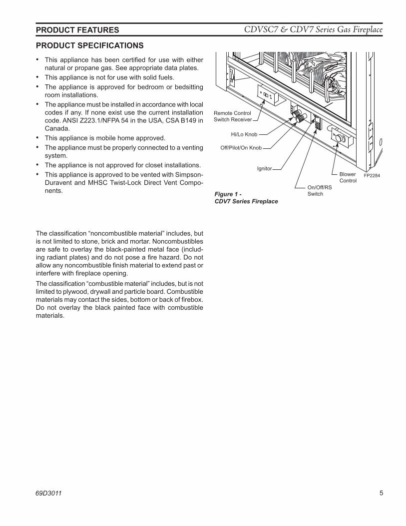
FP2284aCDV7 controls
Off/Pilot/On Knob
Remote Control Switch Receiver
Figure 1 - CDV7 Series Fireplace
Hi/Lo Knob
Blower Control
On/Off/RS Switch
IgnitorFP2284
The classification “noncombustible material” includes, but is not limited to stone, brick and mortar. Noncombustibles are safe to overlay the black-painted metal face (includ-ing radiant plates) and do not pose a fire hazard. Do not allow any noncombustible finish material to extend past or interfere with fireplace opening.The classification “combustible material” includes, but is not limited to plywood, drywall and particle board. Combustible materials may contact the sides, bottom or back of firebox. Do not overlay the black painted face with combustible materials.
CDVSC7 & CDV7 Series Gas Fireplace
6 69D3011
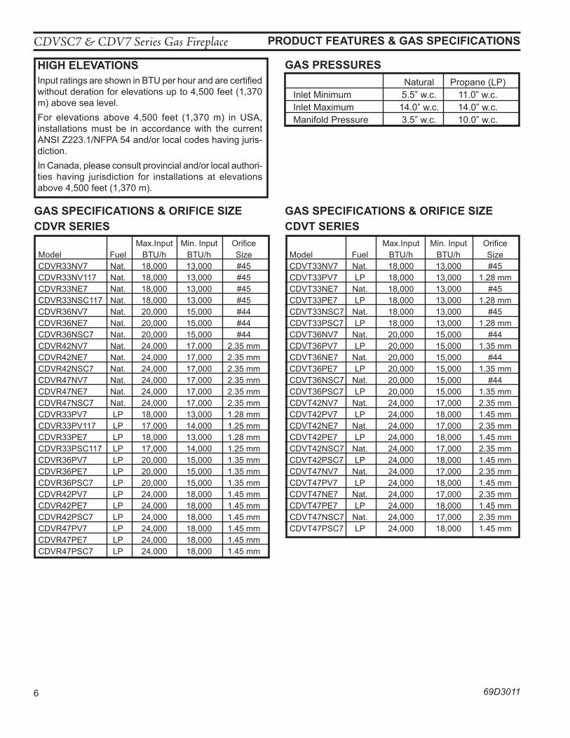
GaS pReSSuReShIGh eleVaTIonSInput ratings are shown in BTU per hour and are certified without deration for elevations up to 4,500 feet (1,370 m) above sea level.For elevations above 4,500 feet (1,370 m) in USA, installations must be in accordance with the current ANSI Z223.1/NFPA 54 and/or local codes having juris-diction.In Canada, please consult provincial and/or local authori-ties having jurisdiction for installations at elevations above 4,500 feet (1,370 m).
GaS SpeCIFICaTIonS & oRIFICe SIZeCDVR SeRIeS Max.Input Min. Input Orifice Model Fuel BTU/h BTU/h Size CDVR33NV7 Nat. 18,000 13,000 #45 CDVR33NV117 Nat. 18,000 13,000 #45 CDVR33NE7 Nat. 18,000 13,000 #45 CDVR33NSC117 Nat. 18,000 13,000 #45 CDVR36NV7 Nat. 20,000 15,000 #44 CDVR36NE7 Nat. 20,000 15,000 #44 CDVR36NSC7 Nat. 20,000 15,000 #44 CDVR42NV7 Nat. 24,000 17,000 2.35 mm CDVR42NE7 Nat. 24,000 17,000 2.35 mm CDVR42NSC7 Nat. 24,000 17,000 2.35 mm CDVR47NV7 Nat. 24,000 17,000 2.35 mm CDVR47NE7 Nat. 24,000 17,000 2.35 mm CDVR47NSC7 Nat. 24,000 17,000 2.35 mm CDVR33PV7 LP 18,000 13,000 1.28 mm CDVR33PV117 LP 17,000 14,000 1.25 mm CDVR33PE7 LP 18,000 13,000 1.28 mm CDVR33PSC117 LP 17,000 14,000 1.25 mm CDVR36PV7 LP 20,000 15,000 1.35 mm CDVR36PE7 LP 20,000 15,000 1.35 mm CDVR36PSC7 LP 20,000 15,000 1.35 mm CDVR42PV7 LP 24,000 18,000 1.45 mm CDVR42PE7 LP 24,000 18,000 1.45 mm CDVR42PSC7 LP 24,000 18,000 1.45 mm CDVR47PV7 LP 24,000 18,000 1.45 mm CDVR47PE7 LP 24,000 18,000 1.45 mm CDVR47PSC7 LP 24,000 18,000 1.45 mm
Natural Propane (LP) Inlet Minimum 5.5” w.c. 11.0” w.c. Inlet Maximum 14.0” w.c. 14.0” w.c. Manifold Pressure 3.5” w.c. 10.0” w.c.
pRoDuCT FeaTuReS & GaS SpeCIFICaTIonS
GaS SpeCIFICaTIonS & oRIFICe SIZeCDVT SeRIeS Max.Input Min. Input Orifice Model Fuel BTU/h BTU/h Size CDVT33NV7 Nat. 18,000 13,000 #45 CDVT33PV7 LP 18,000 13,000 1.28 mm CDVT33NE7 Nat. 18,000 13,000 #45 CDVT33PE7 LP 18,000 13,000 1.28 mm CDVT33NSC7 Nat. 18,000 13,000 #45 CDVT33PSC7 LP 18,000 13,000 1.28 mm CDVT36NV7 Nat. 20,000 15,000 #44 CDVT36PV7 LP 20,000 15,000 1.35 mm CDVT36NE7 Nat. 20,000 15,000 #44 CDVT36PE7 LP 20,000 15,000 1.35 mm CDVT36NSC7 Nat. 20,000 15,000 #44 CDVT36PSC7 LP 20,000 15,000 1.35 mm CDVT42NV7 Nat. 24,000 17,000 2.35 mm CDVT42PV7 LP 24,000 18,000 1.45 mm CDVT42NE7 Nat. 24,000 17,000 2.35 mm CDVT42PE7 LP 24,000 18,000 1.45 mm CDVT42NSC7 Nat. 24,000 17,000 2.35 mm CDVT42PSC7 LP 24,000 18,000 1.45 mm CDVT47NV7 Nat. 24,000 17,000 2.35 mm CDVT47PV7 LP 24,000 18,000 1.45 mm CDVT47NE7 Nat. 24,000 17,000 2.35 mm CDVT47PE7 LP 24,000 18,000 1.45 mm CDVT47NSC7 Nat. 24,000 17,000 2.35 mm CDVT47PSC7 LP 24,000 18,000 1.45 mm
CDVSC7 & CDV7 Series Gas Fireplace
69D3011 7
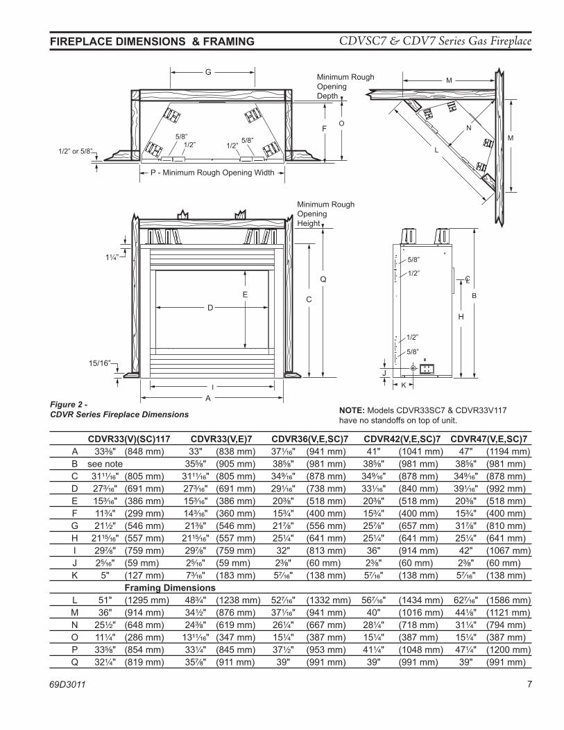
Figure 2 - CDVR Series Fireplace Dimensions
FIReplaCe DIMenSIonS & FRaMInG
G
F
H
A
J
C
Q
D
E
1 ”
15/16”
P - Minimum Rough Opening Width
Minimum RoughOpening Depth
1/2” 5/8”5/8”1/2”
Minimum RoughOpening Height
CL
5/8”
1/2”
5/8”
1/2”
I K
L
M
O
M
N
B
693011CDVR7 DIMS
1/2” or 5/8”
CDVR33(V)(SC)117 CDVR33(V,e)7 CDVR36(V,e,SC)7 CDVR42(V,e,SC)7 CDVR47(V,e,SC)7 A 33C\," (848 mm) 33" (838 mm) 37Z\zn" (941 mm) 41" (1041 mm) 47" (1194 mm) B see note 35B\," (905 mm) 38B\," (981 mm) 38B\," (981 mm) 38B\," (981 mm) C 31ZZ\zn" (805 mm) 31ZZ\zn" (805 mm) 34>\zn" (878 mm) 34>\zn" (878 mm) 34>\zn" (878 mm) D 27C\zn" (691 mm) 27C\zn" (691 mm) 29Z\zn" (738 mm) 33Z\zn" (840 mm) 39Z\zn" (992 mm) E 15C\zn" (386 mm) 15C\zn" (386 mm) 20C\," (518 mm) 20C\," (518 mm) 20C\," (518 mm) F 11C\v" (299 mm) 14C\zn" (360 mm) 15C\v" (400 mm) 15C\v" (400 mm) 15C\v" (400 mm) G 21Z\x" (546 mm) 21C\," (546 mm) 21M\," (556 mm) 25M\," (657 mm) 31M\," (810 mm) H 21ZB\zn" (557 mm) 21ZB\zn" (557 mm) 25Z\v" (641 mm) 25Z\v" (641 mm) 25Z\v" (641 mm) I 29M\," (759 mm) 29M\," (759 mm) 32" (813 mm) 36" (914 mm) 42" (1067 mm) J 2B\zn" (59 mm) 2B\zn" (59 mm) 2C\," (60 mm) 2C\," (60 mm) 2C\," (60 mm) K 5" (127 mm) 7C\zn" (183 mm) 5M\zn" (138 mm) 5M\zn" (138 mm) 5M\zn" (138 mm) Framing Dimensions L 51" (1295 mm) 48C\v" (1238 mm) 52M\zn" (1332 mm) 56M\zn" (1434 mm) 62M\zn" (1586 mm) M 36" (914 mm) 34Z\x" (876 mm) 37Z\zn" (941 mm) 40" (1016 mm) 44Z\," (1121 mm) N 25Z\x" (648 mm) 24C\," (619 mm) 26Z\v" (667 mm) 28Z\v" (718 mm) 31Z\v" (794 mm) O 11Z\v" (286 mm) 13ZZ\zn" (347 mm) 15Z\v" (387 mm) 15Z\v" (387 mm) 15Z\v" (387 mm) P 33B\," (854 mm) 33Z\v" (845 mm) 37Z\x" (953 mm) 41Z\v" (1048 mm) 47Z\v" (1200 mm) Q 32Z\v" (819 mm) 35M\," (911 mm) 39" (991 mm) 39" (991 mm) 39" (991 mm)
noTe: Models CDVR33SC7 & CDVR33V117 have no standoffs on top of unit.
CDVSC7 & CDV7 Series Gas Fireplace
8 69D3011
FIReplaCe DIMenSIonS & FRaMInG
G
F
H
AJ
C
R
D
E
1 ”
15/16”
Q - Minimum Rough Opening Width
P
Minimum RoughOpening Depth
1/2” 5/8”5/8”1/2”
Minimum RoughOpening Height
5/8”
1/2”
5/8”
1/2”
I
KL
M
O
N
N
B
693011CDVT7 top dims
1/2” or 5/8”
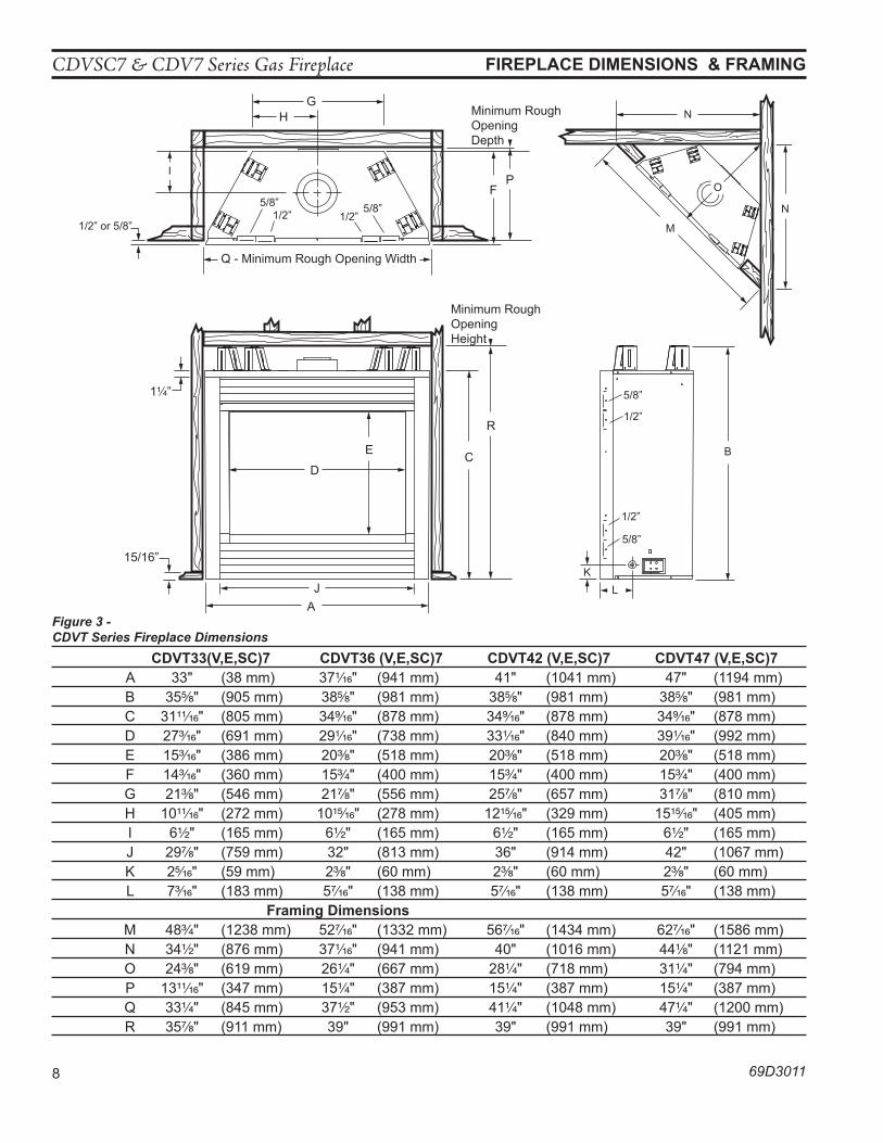
Figure 3 - CDVT Series Fireplace Dimensions CDVT33(V,e,SC)7 CDVT36 (V,e,SC)7 CDVT42 (V,e,SC)7 CDVT47 (V,e,SC)7 A 33" (38 mm) 37Z\zn" (941 mm) 41" (1041 mm) 47" (1194 mm) B 35B\," (905 mm) 38B\," (981 mm) 38B\," (981 mm) 38B\," (981 mm) C 31ZZ\zn" (805 mm) 34>\zn" (878 mm) 34>\zn" (878 mm) 34>\zn" (878 mm) D 27C\zn" (691 mm) 29Z\zn" (738 mm) 33Z\zn" (840 mm) 39Z\zn" (992 mm) E 15C\zn" (386 mm) 20C\," (518 mm) 20C\," (518 mm) 20C\," (518 mm) F 14C\zn" (360 mm) 15C\v" (400 mm) 15C\v" (400 mm) 15C\v" (400 mm) G 21C\," (546 mm) 21M\," (556 mm) 25M\," (657 mm) 31M\," (810 mm) H 10ZZ\zn" (272 mm) 10ZB\zn" (278 mm) 12ZB\zn" (329 mm) 15ZB\zn" (405 mm) I 6Z\x" (165 mm) 6Z\x" (165 mm) 6Z\x" (165 mm) 6Z\x" (165 mm) J 29M\," (759 mm) 32" (813 mm) 36" (914 mm) 42" (1067 mm) K 2B\zn" (59 mm) 2C\," (60 mm) 2C\," (60 mm) 2C\," (60 mm) L 7C\zn" (183 mm) 5M\zn" (138 mm) 5M\zn" (138 mm) 5M\zn" (138 mm) Framing Dimensions M 48C\v" (1238 mm) 52M\zn" (1332 mm) 56M\zn" (1434 mm) 62M\zn" (1586 mm) N 34Z\x" (876 mm) 37Z\zn" (941 mm) 40" (1016 mm) 44Z\," (1121 mm) O 24C\," (619 mm) 26Z\v" (667 mm) 28Z\v" (718 mm) 31Z\v" (794 mm) P 13ZZ\zn" (347 mm) 15Z\v" (387 mm) 15Z\v" (387 mm) 15Z\v" (387 mm) Q 33Z\v" (845 mm) 37Z\x" (953 mm) 41Z\v" (1048 mm) 47Z\v" (1200 mm) R 35M\," (911 mm) 39" (991 mm) 39" (991 mm) 39" (991 mm)
CDVSC7 & CDV7 Series Gas Fireplace
69D3011 9
pRe-InSTallaTIon InFoRMaTIon
BeFoRe you STaRTRead this homeowner manual thoroughly and follow all instructions carefully. Inspect all contents for shipping damage and immediately inform your dealer if any damage is found. Do not install any unit with damaged, incomplete, or substitute parts. Check your packing list to verify that all listed parts have been received. You should have the following:
• Fireplace (Firebox and Burner System) • Log Set • Volcanic Rock• Rock Wool
ITeMS RequIReD FoR InSTallaTIonTools: Building Supplies:• Phillips Screwdriver • Framing Materials• Hammer • Wall Finishing Materials• Saw and/or saber saw • Level• Electric Drill and Bits • Tee Joint• Pliers • Measuring Tape• Square • Pipe Wrench• Caulking Material (Noncombustible) • Fireplace Surround Material (Noncombustible) • Piping Complying with Local Codes• Pipe Sealant Approved for use with Propane/LPG (Resistant to Sulfur Compounds)
FIReBox FRaMInG FoR CDVRFirebox framing can be built before or after the appliance is set in place. Construct firebox framing following Figure 2 for your specific installation requirements. Refer to Figure 2 for firebox dimensions. The framing headers may rest on the top of the firebox standoffs. Do not bring headers below top of standoffs. noTe: CDVR33SC7 & CDVR33117 do not have standoffs.The firebox may be installed directly on a combustible floor or raised on a platform of an appropriate height. When the firebox is installed directly on carpeting, tile, or other combustible material, other than wood flooring, the firebox shall be installed on a metal or wood panel extending the full width and depth of the enclosure.
wa
Rn
InG Do not fill spaces around firebox with
insulation or other materials. This could cause a fire.
FIReBox FRaMInG FoR CDVTFirebox framing can be built before or after the appliance is set in place. Construct firebox framing following Figure 3 for your specific installation requirements. Refer to Figure 3 for firebox dimensions. The framing headers may rest on the top of the firebox standoffs. Do not bring headers below top of standoffs.The firebox may be installed directly on a combustible floor or raised on a platform of an appropriate height. When the firebox is installed directly on carpeting, tile, or other combustible material, other than wood flooring, the firebox shall be installed on a metal or wood panel extending the full width and depth of the enclosure.
no
Te
ColD ClIMaTe InSulaTIonIf you live in a cold climate, seal all cracks around your appliance, and wherever cold air could enter the room, with noncombustible material. It is especially important to insulate the outside chase cavity between the studs and under the floor on which the appliance rests, if the floor is above ground level.
CDVSC7 & CDV7 Series Gas Fireplace
10 69D3011
FIReplaCe loCaTIonPlan for the installation of your appliance. This includes determining where the unit is to be installed, the vent configuration to be used, framing and finishing details, and whether any optional accessories (i.e. blower, wall switch, or remote control) are desired. Consult your local building code agency to ensure compliance with local codes, including permits and inspections.The following factors should be taken into consideration:
• Clearance to side-wall, ceiling, woodwork, and windows. Minimum clearances to combustibles must be maintained.
• This fireplace may be installed along a wall, across a corner, or use an exterior chase. Refer to Figure 4 for suggested locations.
• Location should be out of high traffic areas and away from furniture and draperies due to heat from appliance.
• Never obstruct the front opening of the fireplace.• Do not install in the vicinity where gasoline or other flammable liquids may be stored.• Vent pipe routing. See Venting section found in this manual for allowable venting configura-
tions.• These units can be installed in a bedroom. See National Fuel Gas Code ANSI Z233.1/NFPA 54
— (current edition), the Uniform Mechanical Code — (current edition), and Local Building Codes for specific installation requirements.
pRe-InSTallaTIon InFoRMaTIon
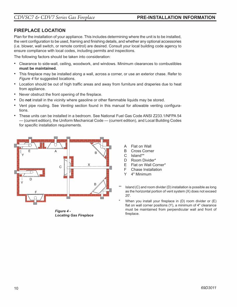
Figure 4 - Locating Gas Fireplace
** Island (C) and room divider (D) installation is possible as long as the horizontal portion of vent system (X) does not exceed 20'.
* When you install your fireplace in (D) room divider or (E) flat on wall corner positions (Y), a minimum of 4" clearance must be maintained from perpendicular wall and front of fireplace.
YE A B
C
D
F
Y B
X
LU584-1Locating unit2/4/99 djt
A Flat on WallB Cross CornerC Island**D Room Divider*E Flat on Wall Corner*F Chase InstallationY 4" Minimum
CDVSC7 & CDV7 Series Gas Fireplace
69D3011 11
CleaRanCeS
CleaRanCeS To CoMBuSTIBleS w
aR
nIn
G
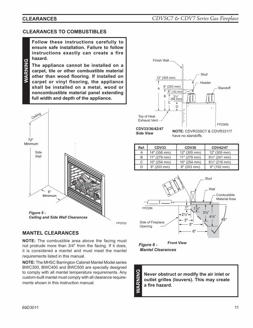
Follow these instructions carefully to ensure safe installation. Failure to follow instructions exactly can create a fire hazard.The appliance cannot be installed on a carpet, tile or other combustible material other than wood flooring. If installed on carpet or vinyl flooring, the appliance shall be installed on a metal, wood or noncombustible material panel extending full width and depth of the appliance.
72" Minimum
6”Minimum
fP2032wall clearances
Figure 5 - Ceiling and Side Wall Clearances
FP2032
Ceiling
Side Wall
FP2285bmantel clearances
12” (305 mm)
8” (203 mm)6” (152 mm)
2 ” (64 mm)
A
B
CD
Finish Wall
Header
Stud
Standoff
Top of Heat Exhaust Vent
FP2285bCDV33/36/42/47Side View
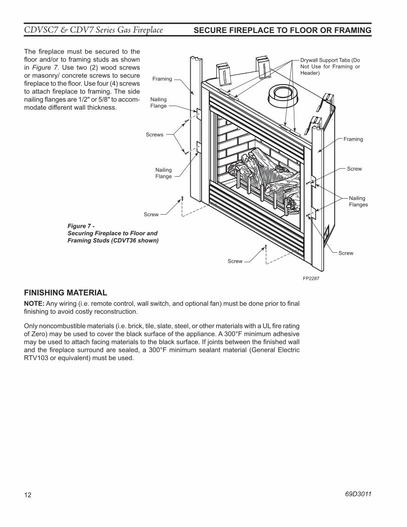
ManTel CleaRanCeS noTe: The combustible area above the facing must not protrude more than 3/4" from the facing. If it does, it is considered a mantel and must meet the mantel requirements listed in this manual. noTe: The MHSC Barrington Cabinet Mantel Model series BWC300, BWC400 and BWC500 are specially designed to comply with all mantel temperature requirements. Any custom-built mantel must comply with all clearance require-ments shown in this instruction manual.
wa
Rn
InG never obstruct or modify the air inlet or
outlet grilles (louvers). This may create a fire hazard.
Figure 6 - Mantel Clearances
Front View
6"
5"3" 45°
1"
2 ”
1 ”3 ”
4 ”
FP2286Mantel leg clear
Side of Fireplace Opening
Stud
Wall
FP2286
Combustible Material Area
noTe: CDVR33SC7 & CDVR33117 have no standoffs.
Ref. CDV33 CDV36 CDV42/47 A 14" (356 mm) 12" (305 mm) 12" (305 mm) B 11" (279 mm) 11" (279 mm) 9Z\x" (241 mm) C 10" (254 mm) 10" (254 mm) 8Z\x" (216 mm) D 8" (203 mm) 8" (203 mm) 6" (152 mm)
CDVSC7 & CDV7 Series Gas Fireplace
12 69D3011
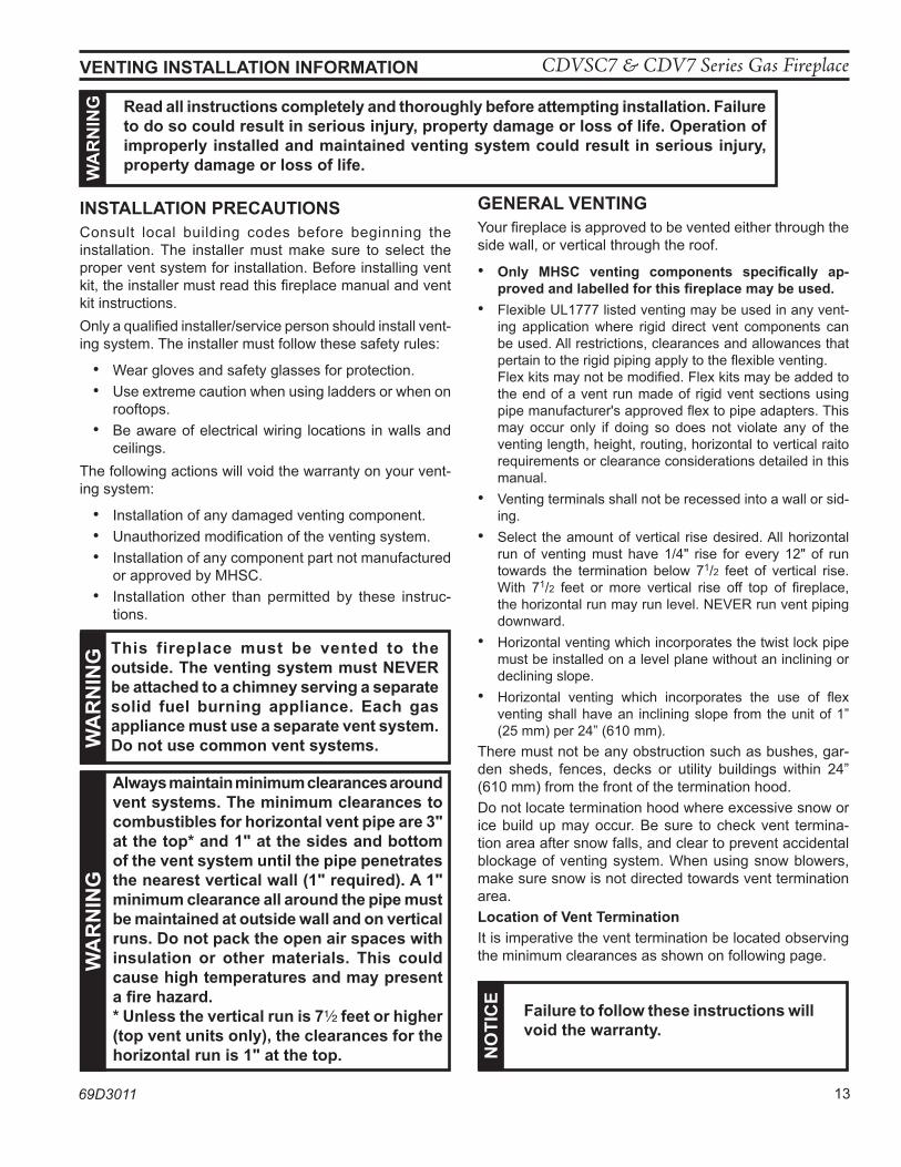
The fireplace must be secured to the floor and/or to framing studs as shown in Figure 7. Use two (2) wood screws or masonry/ concrete screws to secure fireplace to the floor. Use four (4) screws to attach fireplace to framing. The side nailing flanges are 1/2" or 5/8" to accom-modate different wall thickness.
SeCuRe FIReplaCe To FlooR oR FRaMInG
Figure 7 - Securing Fireplace to Floor and Framing Studs (CDVT36 shown)
FP2287secure fireplace
Screw
Framing
Framing
Nailing Flange
Screws
Screw
Nailing Flange
Nailing Flanges
Drywall Support Tabs (Do Not Use for Framing or Header)
Screw
Screw
FP2287
FInIShInG MaTeRIalnoTe: Any wiring (i.e. remote control, wall switch, and optional fan) must be done prior to final finishing to avoid costly reconstruction.
Only noncombustible materials (i.e. brick, tile, slate, steel, or other materials with a UL fire rating of Zero) may be used to cover the black surface of the appliance. A 300°F minimum adhesive may be used to attach facing materials to the black surface. If joints between the finished wall and the fireplace surround are sealed, a 300°F minimum sealant material (General Electric RTV103 or equivalent) must be used.
CDVSC7 & CDV7 Series Gas Fireplace
69D3011 13
InSTallaTIon pReCauTIonSConsult local building codes before beginning the installation. The installer must make sure to select the proper vent system for installation. Before installing vent kit, the installer must read this fireplace manual and vent kit instructions. Only a qualified installer/service person should install vent-ing system. The installer must follow these safety rules:
• Wear gloves and safety glasses for protection. • Use extreme caution when using ladders or when on
rooftops. • Be aware of electrical wiring locations in walls and
ceilings.The following actions will void the warranty on your vent-ing system:
• Installation of any damaged venting component. • Unauthorized modification of the venting system. • Installation of any component part not manufactured
or approved by MHSC. • Installation other than permitted by these instruc-
tions.
VenTInG InSTallaTIon InFoRMaTIonw
aR
nIn
G Read all instructions completely and thoroughly before attempting installation. Failure to do so could result in serious injury, property damage or loss of life. operation of improperly installed and maintained venting system could result in serious injury, property damage or loss of life.
no
TIC
e
Failure to follow these instructions will void the warranty.
always maintain minimum clearances around vent systems. The minimum clearances to combustibles for horizontal vent pipe are 3" at the top* and 1" at the sides and bottom of the vent system until the pipe penetrates the nearest vertical wall (1" required). a 1" minimum clearance all around the pipe must be maintained at outside wall and on vertical runs. Do not pack the open air spaces with insulation or other materials. This could cause high temperatures and may present a fire hazard.* unless the vertical run is 7Z\x feet or higher (top vent units only), the clearances for the horizontal run is 1" at the top.
wa
Rn
InG
This fireplace must be vented to the outside. The venting system must neVeR be attached to a chimney serving a separate solid fuel burning appliance. each gas appliance must use a separate vent system. Do not use common vent systems.w
aR
nIn
G
GeneRal VenTInGYour fireplace is approved to be vented either through the side wall, or vertical through the roof.
• only MhSC venting components specifically ap-proved and labelled for this fireplace may be used.
• Flexible UL1777 listed venting may be used in any vent-ing application where rigid direct vent components can be used. All restrictions, clearances and allowances that pertain to the rigid piping apply to the flexible venting.
Flex kits may not be modified. Flex kits may be added to the end of a vent run made of rigid vent sections using pipe manufacturer's approved flex to pipe adapters. This may occur only if doing so does not violate any of the venting length, height, routing, horizontal to vertical raito requirements or clearance considerations detailed in this manual.
• Venting terminals shall not be recessed into a wall or sid-ing.
• Select the amount of vertical rise desired. All horizontal run of venting must have 1/4" rise for every 12" of run towards the termination below 71/2 feet of vertical rise. With 71/2 feet or more vertical rise off top of fireplace, the horizontal run may run level. NEVER run vent piping downward.
• Horizontal venting which incorporates the twist lock pipe must be installed on a level plane without an inclining or declining slope.
• Horizontal venting which incorporates the use of flex venting shall have an inclining slope from the unit of 1” (25 mm) per 24” (610 mm).
There must not be any obstruction such as bushes, gar-den sheds, fences, decks or utility buildings within 24” (610 mm) from the front of the termination hood.Do not locate termination hood where excessive snow or ice build up may occur. Be sure to check vent termina-tion area after snow falls, and clear to prevent accidental blockage of venting system. When using snow blowers, make sure snow is not directed towards vent termination area.location of Vent Termination It is imperative the vent termination be located observing the minimum clearances as shown on following page.
CDVSC7 & CDV7 Series Gas Fireplace
14 69D3011
VenTInG InSTallaTIon InFoRMaTIon
V
V
V
V
V
V
V
X
X
X
D
E
B
B B
C
B M
B
A
J K
F
L
VENT TERMINATION AIR SUPPLY INLET AREA WHERE TERMINAL IS NOT PERMITTED
H
I
FixedClosed
OperableOperable
FixedClosed
V B
CFM145a DV Termin Location 5/01/01 Rev. 12/05/01 sta
INSIDE CORNER DETAIL
V
A
G
CFM145a
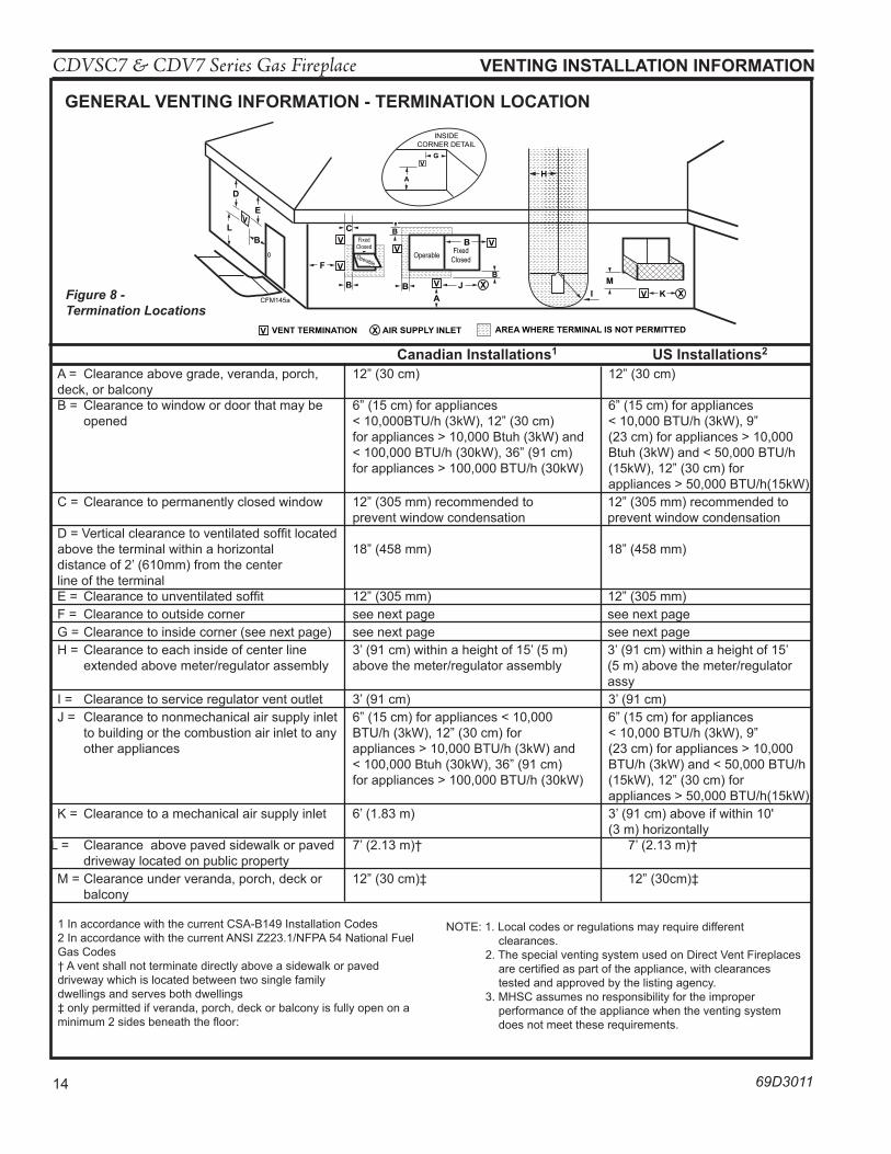
GeneRal VenTInG InFoRMaTIon - TeRMInaTIon loCaTIon
A = Clearance above grade, veranda, porch, 12” (30 cm) 12” (30 cm) deck, or balcony B = Clearance to window or door that may be 6” (15 cm) for appliances 6” (15 cm) for appliances opened < 10,000BTU/h (3kW), 12” (30 cm) < 10,000 BTU/h (3kW), 9” for appliances > 10,000 Btuh (3kW) and (23 cm) for appliances > 10,000 < 100,000 BTU/h (30kW), 36” (91 cm) Btuh (3kW) and < 50,000 BTU/h for appliances > 100,000 BTU/h (30kW) (15kW), 12” (30 cm) for appliances > 50,000 BTU/h(15kW) C = Clearance to permanently closed window 12” (305 mm) recommended to 12” (305 mm) recommended to prevent window condensation prevent window condensation D = Vertical clearance to ventilated soffit located above the terminal within a horizontal 18” (458 mm) 18” (458 mm) distance of 2’ (610mm) from the center line of the terminal E = Clearance to unventilated soffit 12” (305 mm) 12” (305 mm) F = Clearance to outside corner see next page see next page G = Clearance to inside corner (see next page) see next page see next page H = Clearance to each inside of center line 3’ (91 cm) within a height of 15’ (5 m) 3’ (91 cm) within a height of 15’ extended above meter/regulator assembly above the meter/regulator assembly (5 m) above the meter/regulator assy I = Clearance to service regulator vent outlet 3’ (91 cm) 3’ (91 cm) J = Clearance to nonmechanical air supply inlet 6” (15 cm) for appliances < 10,000 6” (15 cm) for appliances to building or the combustion air inlet to any BTU/h (3kW), 12” (30 cm) for < 10,000 BTU/h (3kW), 9” other appliances appliances > 10,000 BTU/h (3kW) and (23 cm) for appliances > 10,000 < 100,000 Btuh (30kW), 36” (91 cm) BTU/h (3kW) and < 50,000 BTU/h for appliances > 100,000 BTU/h (30kW) (15kW), 12” (30 cm) for appliances > 50,000 BTU/h(15kW) K = Clearance to a mechanical air supply inlet 6’ (1.83 m) 3’ (91 cm) above if within 10' (3 m) horizontallyL = Clearance above paved sidewalk or paved 7’ (2.13 m)† 7’ (2.13 m)† driveway located on public property M = Clearance under veranda, porch, deck or 12” (30 cm)� 12” (30cm)� balcony
1 In accordance with the current CSA-B149 Installation Codes2 In accordance with the current ANSI Z223.1/NFPA 54 National Fuel Gas Codes† A vent shall not terminate directly above a sidewalk or paved driveway which is located between two single family dwellings and serves both dwellings� only permitted if veranda, porch, deck or balcony is fully open on a minimum 2 sides beneath the floor:
Canadian Installations1 uS Installations2
NOTE: 1. Local codes or regulations may require different clearances. 2. The special venting system used on Direct Vent Fireplaces are certified as part of the appliance, with clearances tested and approved by the listing agency. 3. MHSC assumes no responsibility for the improper performance of the appliance when the venting system does not meet these requirements.
Figure 8 - Termination Locations
CDVSC7 & CDV7 Series Gas Fireplace
69D3011 15
VenTInG InSTallaTIon InFoRMaTIon
Outside CornerInside Corner
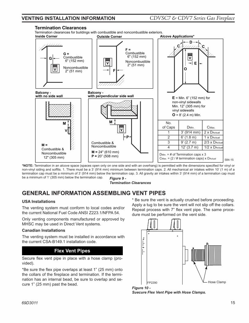
Termination ClearancesTermination clearances for buildings with combustible and noncombustible exteriors.
G =Combustible 6" (152 mm)
Noncombustible 2" (51 mm)
F =Combustible 6" (152 mm) Noncombustible 2" (51 mm)
G
Balcony - with no side wall
M = Combustible &Noncombustible 12" (305 mm)
M
Balcony - with perpendicular side wall
M = 24" (610 mm)P = 20” (508 mm)
M
F
Alcove Applications*
CD
C
E
V
V
Combustible &Noncombustible
V
V
V
E = Min. 6” (152 mm) for non-vinyl sidewallsMin. 12” (305 mm) forvinyl sidewallsO = 8’ (2.4 m) Min.
O
P
584-15
No. of Caps DMin. CMax.
1 3’ (914 mm) 2 x DActual
2 6’ (1.8 m) 1 x DActual
3 9’ (2.7 m) 2/3 x DActual
4 12’ (3.7 m) 1/2 x DActual
DMin. = # of Termination caps x 3CMax. = (2 / # termination caps) x DActual
*noTe: Termination in an alcove space (spaces open only on one side and with an overhang) is permitted with the dimensions specified for vinyl or non-vinyl siding and soffits. 1. There must be a 3’ (914 mm) minimum between termination caps. 2. All mechanical air intakes within 10’ (1 m) of a termination cap must be a minimum of 3’ (914 mm) below the termination cap. 3. All gravity air intakes within 3’ (914 mm) of a termination cap must be a minimum of 1’ (305 mm) below the termination cap.
GeneRal InFoRMaTIon aSSeMBlInG VenT pIpeSuSa InstallationsThe venting system must conform to local codes and/or the current National Fuel Code ANSI Z223.1/NFPA 54.Only venting components manufactured or approved by MHSC may be used in Direct Vent systems.Canadian InstallationsThe venting system must be installed in accordance with the current CSA-B149.1 installation code.
Flex Vent pipesSecure flex vent pipe in place with a hose clamp (pro-vided).*Be sure the flex pipe overlaps at least 1” (25 mm) onto the collars of the fireplace and termination. If the termi-nation has an internal bead, be sure to overlap and se-cure 1” (25 mm) past the bead.
* Be sure the vent is actually crushed before proceeding. Apply a tug to be sure the vent will not slip off the collars.Repeat process with 7” flex vent pipe. The same proce-dure must be performed on the vent side.
FP2290flex vent
Hose ClampFP2290
Figure 10 - Suecure Flex Vent Pipe with Hose Clamps.
Figure 9 - Termination Clearances
CDVSC7 & CDV7 Series Gas Fireplace
16 69D3011
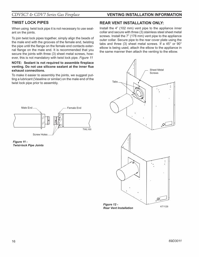
TwIST loCK pIpeSWhen using twist lock pipe it is not necessary to use seal-ant on the joints.
To join twist lock pipes together, simply align the beads of the male end with the grooves of the female end, twisting the pipe until the flange on the female end contacts exter-nal flange on the male end. It is recommended that you secure the joints with three (3) sheet metal screws, how-ever, this is not mandatory with twist lock pipe. Figure 11noTe: Sealant is not required to assemble fireplace venting. Do not use silicone sealant at the inner flue exhaust connections.To make it easier to assembly the joints, we suggest put-ting a lubricant (Vaseline or similar) on the male end of the twist lock pipe prior to assembly.
TWL100Twist Lock Pipe3/12/99 djt
Male End Female End
Screw Holes
TWL100
Figure 11 -Twist-lock Pipe Joints
VenTInG InSTallaTIon InFoRMaTIon
ReaR VenT InSTallaTIon only:Install the 4” (102 mm) vent pipe to the appliance inner collar and secure with three (3) stainless steel sheet metal screws. Install the 7” (178 mm) vent pipe to the appliance outer collar. Secure pipe to the rear cover plate using the tabs and three (3) sheet metal screws. If a 45° or 90° elbow is being used, attach the elbow to the appliance in the same manner then attach the venting to the elbow.
KT1129cdv add rear vent
Sheet Metal Screws
Tabs
KT1129Figure 12 - Rear Vent Installation
CDVSC7 & CDV7 Series Gas Fireplace
69D3011 17
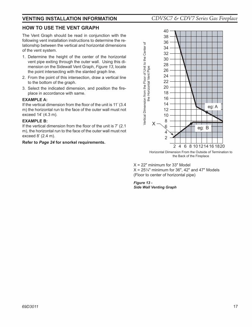
how To uSe The VenT GRaphThe Vent Graph should be read in conjunction with the following vent installation instructions to determine the re-lationship between the vertical and horizontal dimensions of the vent system.1. Determine the height of the center of the horizontal
vent pipe exiting through the outer wall. Using this di-mension on the Sidewall Vent Graph, Figure 13, locate the point intersecting with the slanted graph line.
2. From the point of this intersection, draw a vertical line to the bottom of the graph.
3. Select the indicated dimension, and position the fire-place in accordance with same.
exaMple a: If the vertical dimension from the floor of the unit is 11’ (3.4 m) the horizontal run to the face of the outer wall must not exceed 14’ (4.3 m).exaMple B: If the vertical dimension from the floor of the unit is 7’ (2.1 m), the horizontal run to the face of the outer wall must not exceed 8’ (2.4 m).Refer to Page 24 for snorkel requirements.
403836343230282624222018161412108642
2 4 6 8 10 12 14 16 18 20
eg: A
FP2291vent graph
XVerti
cal D
imen
sion
from
the
Floo
r of U
nit t
o th
e C
ente
r of
the
Hor
izon
tal V
ent P
ipe
Horizontal Dimension From the Outside of Termination to the Back of the Fireplace
Figure 13 - Side Wall Venting Graph
X = 22" minimum for 33" ModelX = 25Z\v" minimum for 36", 42" and 47" Models(Floor to center of horizontal pipe)
VenTInG InSTallaTIon InFoRMaTIon

CDVSC7 & CDV7 Series Gas Fireplace
18 69D3011
3"1"
1"
1"
FP2288TV rear vent
VenTInG InSTallaTIon
Figure 14 - Combustible Clearances for Vent Pipe
A Minimum of 3" Clearance to the Top Is Required Along Horizontal Length until Flue Pipe Penetrates Outside Wall.
A Minimum 1" C learance to Combust ib les Permi t ted A l l Around Flue at Outside Wall
VenT pIpe CleaRanCeS
Rear Vent: horizontal sections of this vent system require a minimum of 3" clearances to combustibles at the top of the flue and 1" clearance at the sides and bottom until the flue penetrates the outside wall. a minimum 1" clearance all around the flue is acceptable at this point of penetration.Vertical sections of this vent system require a minimum of 1" clearance to combustibles on all sides of the pipe.
wa
Rn
InG
Top Vent: horizontal sections of this vent system require a minimum of 3" clearances to combustibles at the top of the flue and 1" clearance at the sides and bottom until the flue penetrates the outside wall. a minimum 1" clearance all around the flue is acceptable at this point of penetration. If vertical rise is 71/2 feet or higher when top venting, the clearance to combustibles is 1" on all sides of the horizontal run.Vertical sections of this vent system require a minimum of 1" clearance to combustibles on all sides of the pipe.
wa
Rn
InG
1"3"
1"1"
FP2289RV rear vent
A Minimum of 3" Clearance to the Top Is Required Along Horizontal Length until Flue Pipe Penetrates Outside Wall.
A Minimum 1" Clearance to Combustibles Permitted All Around Flue at Outside Wall
FP2288FP2289CDVR Series CDVT Series
CDVSC7 & CDV7 Series Gas Fireplace
69D3011 19
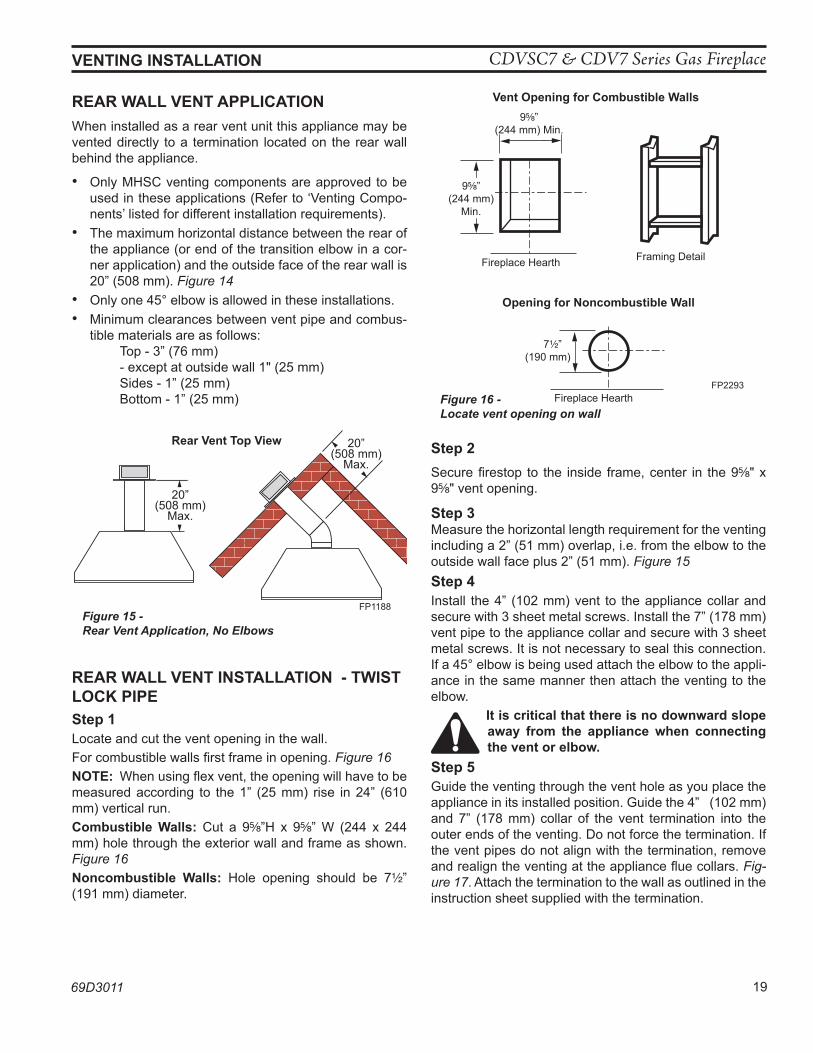
ReaR wall VenT applICaTIonWhen installed as a rear vent unit this appliance may be vented directly to a termination located on the rear wall behind the appliance.
• Only MHSC venting components are approved to be used in these applications (Refer to ‘Venting Compo-nents’ listed for different installation requirements).
• The maximum horizontal distance between the rear of the appliance (or end of the transition elbow in a cor-ner application) and the outside face of the rear wall is 20” (508 mm). Figure 14
• Only one 45° elbow is allowed in these installations.• Minimum clearances between vent pipe and combus-
tible materials are as follows: Top - 3” (76 mm) - except at outside wall 1" (25 mm) Sides - 1” (25 mm) Bottom - 1” (25 mm)
FP1188rear wall install
20”(508 mm)
Max.
20”(508 mm)
Max.
Rear Vent Top View
Figure 15 - Rear Vent Application, No Elbows
ReaR wall VenT InSTallaTIon - TwIST loCK pIpeStep 1Locate and cut the vent opening in the wall.For combustible walls first frame in opening. Figure 16noTe: When using flex vent, the opening will have to be measured according to the 1” (25 mm) rise in 24” (610 mm) vertical run.Combustible walls: Cut a 9B\,”H x 9B\,” W (244 x 244 mm) hole through the exterior wall and frame as shown. Figure 16noncombustible walls: Hole opening should be 7Z\x” (191 mm) diameter.
Step 2Secure firestop to the inside frame, center in the 9B\," x 9B\," vent opening.
Step 3Measure the horizontal length requirement for the venting including a 2” (51 mm) overlap, i.e. from the elbow to the outside wall face plus 2” (51 mm). Figure 15Step 4Install the 4” (102 mm) vent to the appliance collar and secure with 3 sheet metal screws. Install the 7” (178 mm) vent pipe to the appliance collar and secure with 3 sheet metal screws. It is not necessary to seal this connection. If a 45° elbow is being used attach the elbow to the appli-ance in the same manner then attach the venting to the elbow.
It is critical that there is no downward slope away from the appliance when connecting the vent or elbow.
Step 5Guide the venting through the vent hole as you place the appliance in its installed position. Guide the 4” (102 mm) and 7” (178 mm) collar of the vent termination into the outer ends of the venting. Do not force the termination. If the vent pipes do not align with the termination, remove and realign the venting at the appliance flue collars. Fig-ure 17. Attach the termination to the wall as outlined in the instruction sheet supplied with the termination.
VenTInG InSTallaTIon
VO584-100Vent Opening2/99 djt
Vent opening for Combustible walls
9B\,”(244 mm)
Min.
Fireplace Hearth Framing Detail
opening for noncombustible wall
7Z\x”(190 mm)
Fireplace HearthFP2293
Figure 16 - Locate vent opening on wall
9B\,”(244 mm) Min.
FP1188
CDVSC7 & CDV7 Series Gas Fireplace
20 69D3011
VenTInG InSTallaTIon
FP2294Side View Vent Termination1/25/00 djt
Finish WallVent Termination
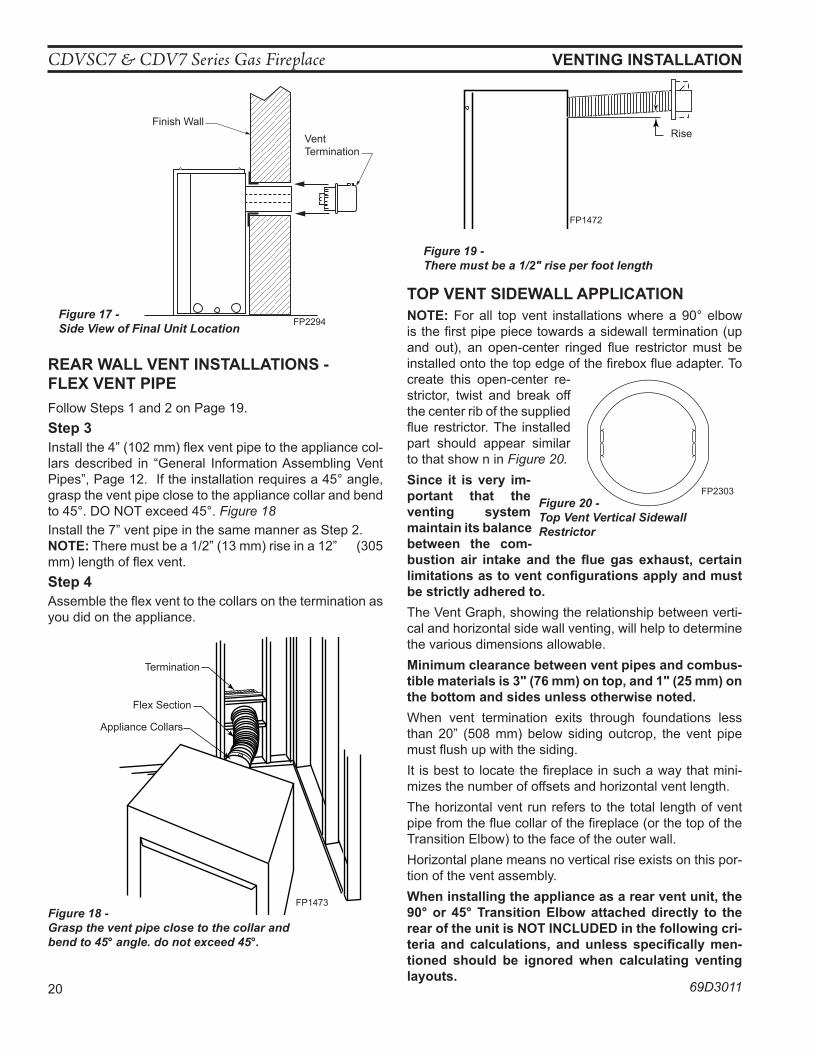
FP2294Figure 17 - Side View of Final Unit Location
ReaR wall VenT InSTallaTIonS - Flex VenT pIpeFollow Steps 1 and 2 on Page 19.Step 3Install the 4” (102 mm) flex vent pipe to the appliance col-lars described in “General Information Assembling Vent Pipes”, Page 12. If the installation requires a 45° angle, grasp the vent pipe close to the appliance collar and bend to 45°. DO NOT exceed 45°. Figure 18Install the 7” vent pipe in the same manner as Step 2.noTe: There must be a 1/2” (13 mm) rise in a 12” (305 mm) length of flex vent. Step 4Assemble the flex vent to the collars on the termination as you did on the appliance.
FP1473corner flex install4/04 djt
Termination
Flex Section
Appliance Collars
FP1473Figure 18 - Grasp the vent pipe close to the collar and bend to 45° angle. do not exceed 45°.
FP1472rise in length4/04 djt
Rise
FP1472
Figure 19 - There must be a 1/2" rise per foot length
Top VenT SIDewall applICaTIonnoTe: For all top vent installations where a 90° elbow is the first pipe piece towards a sidewall termination (up and out), an open-center ringed flue restrictor must be installed onto the top edge of the firebox flue adapter. To create this open-center re-strictor, twist and break off the center rib of the supplied flue restrictor. The installed part should appear similar to that show n in Figure 20. Since it is very im-portant that the venting system maintain its balance between the com-bustion air intake and the flue gas exhaust, certain limitations as to vent configurations apply and must be strictly adhered to.The Vent Graph, showing the relationship between verti-cal and horizontal side wall venting, will help to determine the various dimensions allowable.Minimum clearance between vent pipes and combus-tible materials is 3" (76 mm) on top, and 1" (25 mm) on the bottom and sides unless otherwise noted.When vent termination exits through foundations less than 20” (508 mm) below siding outcrop, the vent pipe must flush up with the siding.It is best to locate the fireplace in such a way that mini-mizes the number of offsets and horizontal vent length. The horizontal vent run refers to the total length of vent pipe from the flue collar of the fireplace (or the top of the Transition Elbow) to the face of the outer wall.Horizontal plane means no vertical rise exists on this por-tion of the vent assembly.when installing the appliance as a rear vent unit, the 90° or 45° Transition elbow attached directly to the rear of the unit is noT InCluDeD in the following cri-teria and calculations, and unless specifically men-tioned should be ignored when calculating venting layouts.
FP2303CDV7 rear restrictor3/09
Figure 20 - Top Vent Vertical Sidewall Restrictor
FP2303
CDVSC7 & CDV7 Series Gas Fireplace
69D3011 21
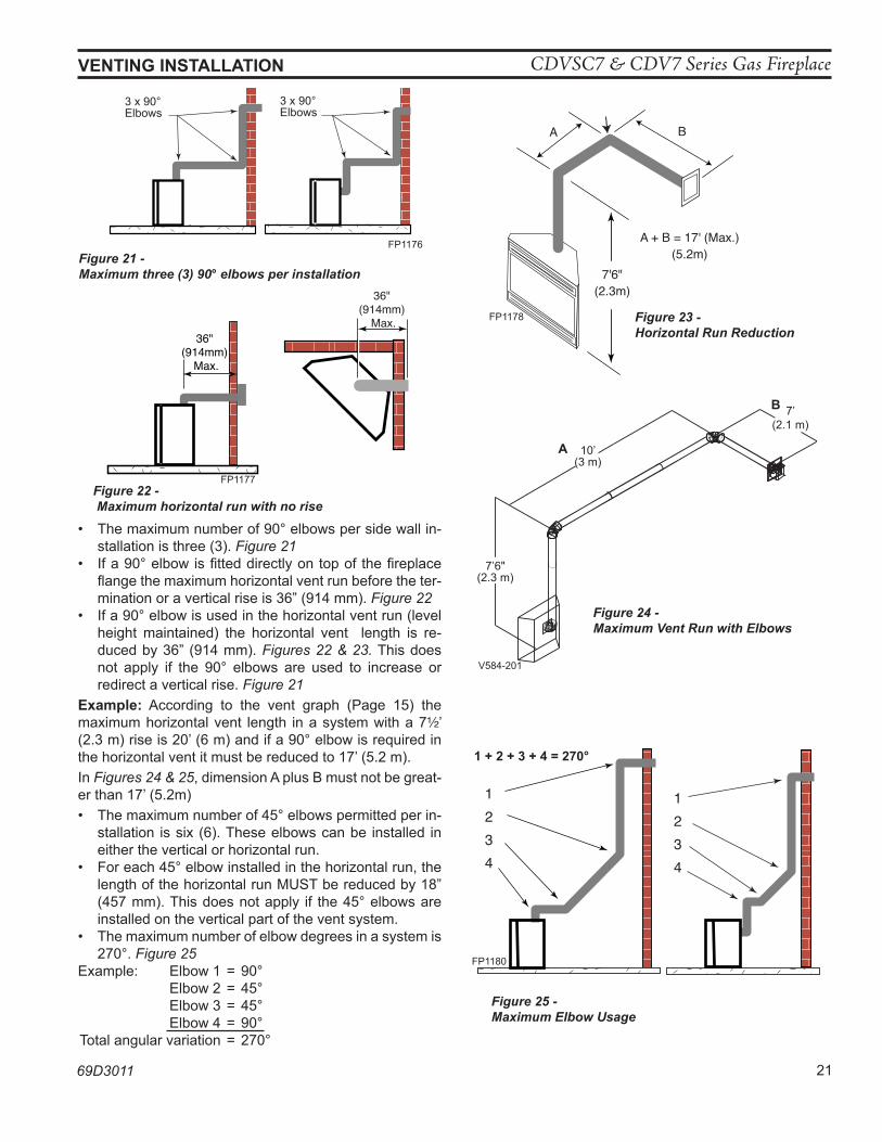
• The maximum number of 90° elbows per side wall in-stallation is three (3). Figure 21
• If a 90° elbow is fitted directly on top of the fireplace flange the maximum horizontal vent run before the ter-mination or a vertical rise is 36” (914 mm). Figure 22
• If a 90° elbow is used in the horizontal vent run (level height maintained) the horizontal vent length is re-duced by 36” (914 mm). Figures 22 & 23. This does not apply if the 90° elbows are used to increase or redirect a vertical rise. Figure 21
example: According to the vent graph (Page 15) the maximum horizontal vent length in a system with a 7Z\x’ (2.3 m) rise is 20’ (6 m) and if a 90° elbow is required in the horizontal vent it must be reduced to 17’ (5.2 m).In Figures 24 & 25, dimension A plus B must not be great-er than 17’ (5.2m)• The maximum number of 45° elbows permitted per in-
stallation is six (6). These elbows can be installed in either the vertical or horizontal run.
• For each 45° elbow installed in the horizontal run, the length of the horizontal run MUST be reduced by 18” (457 mm). This does not apply if the 45° elbows are installed on the vertical part of the vent system.
• The maximum number of elbow degrees in a system is 270°. Figure 25
Example: Elbow 1 = 90° Elbow 2 = 45° Elbow 3 = 45° Elbow 4 = 90° Total angular variation = 270°
3 x 90° Elbows
3 x 90° Elbows
FP1176Figure 21 -Maximum three (3) 90° elbows per installation
Max 20"
Max 20"
36" (914mm)
Max.
36" (914mm)
Max.
FP1177Figure 22 - Maximum horizontal run with no rise
VenTInG InSTallaTIon
7'6"(2.3m)
A B
A + B = 17' (Max.)(5.2m)
FP1178 Figure 23 - Horizontal Run Reduction
V584-201 �Horizontal Run �2/99 djt
a 10’(3 m)
7’(2.1 m)
7’6"(2.3 m)
V584-201
B
Figure 24 - Maximum Vent Run with Elbows
1234
1234
1 + 2 + 3 + 4 = 270°
FP1180
Figure 25 - Maximum Elbow Usage
CDVSC7 & CDV7 Series Gas Fireplace
22 69D3011
VenTInG InSTallaTIon
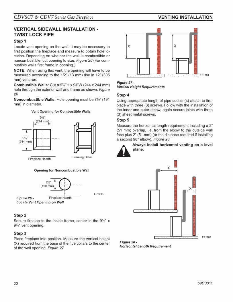
VeRTICal SIDewall InSTallaTIon -TwIST loCK pIpeStep 1Locate vent opening on the wall. It may be necessary to first position the fireplace and measure to obtain hole lo-cation. Depending on whether the wall is combustible or noncombustible, cut opening to size. Figure 26 (For com-bustible walls first frame in opening.)noTe: When using flex vent, the opening will have to be measured according to the 1/2” (13 mm) rise in 12” (305 mm) vent run.Combustible walls: Cut a 9B\,”H x 9%\,”W (244 x 244 mm) hole through the exterior wall and frame as shown. Figure 26noncombustible walls: Hole opening must be 7Z\x” (191 mm) in diameter.
VO584-100Vent Opening2/99 djt
Vent opening for Combustible walls
9B\,”(244 mm)
Fireplace Hearth Framing Detail
opening for noncombustible wall
7Z\x”(190 mm)
Fireplace HearthFP2293
Figure 26 - Locate Vent Opening on Wall
9B\,”(244 mm)
Step 2Secure firestop to the inside frame, center in the 9B\," x 9B\," vent opening.
Step 3Place fireplace into position. Measure the vertical height (X) required from the base of the flue collars to the center of the wall opening. Figure 27
X X
FP1181
Figure 27 - Vertical Height Requirements
Step 4Using appropriate length of pipe section(s) attach to fire-place with three (3) screws. Follow with the installation of the inner and outer elbow, again secure joints with three (3) sheet metal screws. Step 5Measure the horizontal length requirement including a 2” (51 mm) overlap, i.e. from the elbow to the outside wall face plus 2” (51 mm) (or the distance required if installing a second 90° elbow). Figure 28
always install horizontal venting on a level plane.
X
X
FP1182
Figure 28 - Horizontal Length Requirement
CDVSC7 & CDV7 Series Gas Fireplace
69D3011 23
VenTInG InSTallaTIon
Step 6Use appropriate length of pipe sections - telescopic or fixed - and install. The sections which go through the wall are packaged with the starter kit, and can be cut to suit if necessary.Step 7Guide the vent terminations 4” and 7” collard into their respective vent pipes. Double check that the vent pipes overlap the collars by 2” (51 mm). Secure the termina-tion to the wall with screws provided and caulk around the wall plate to weatherproof. As an alternative to screw-ing the termination directly to the wall, you may also use expanding plugs or an approved exterior construction ad-hesive. You may also attach the termination with screws through the inner body into the 4” vent pipe, however for this method, you must extend the 4” pipe approximately 6” (152 mm) beyond the outer face of the wall.
Support horizontal pipes every 36” (914 mm) with metal pipe straps.
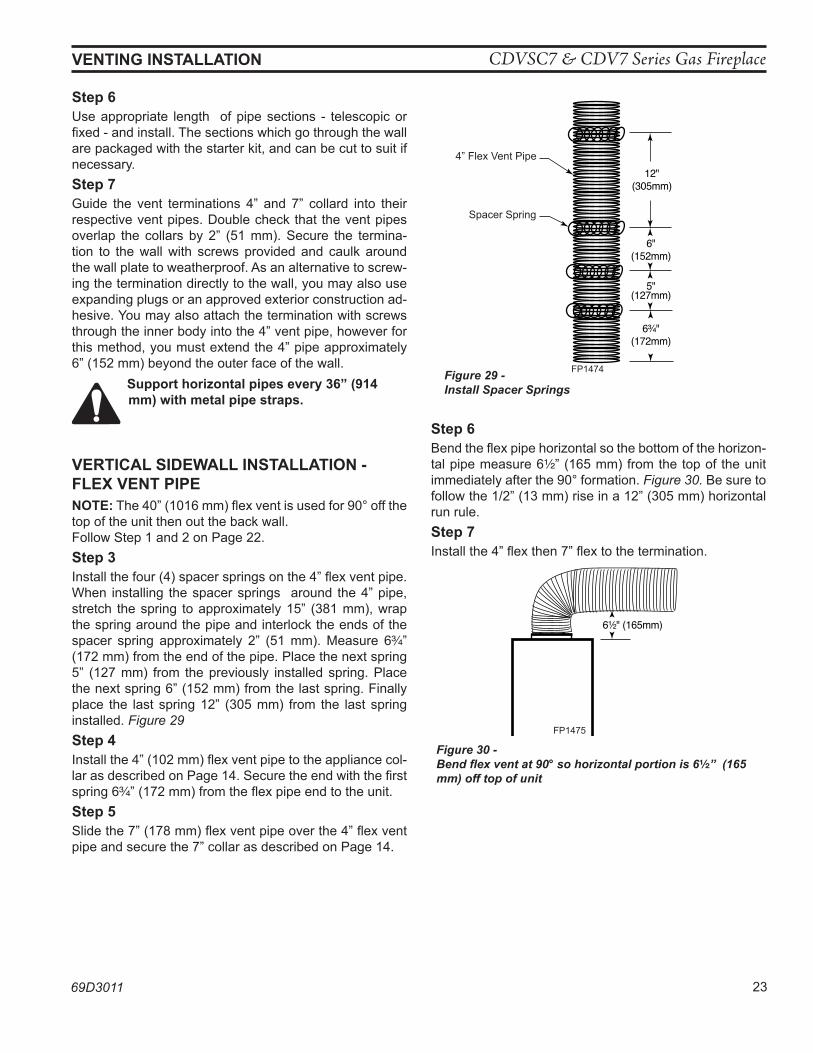
VeRTICal SIDewall InSTallaTIon - Flex VenT pIpe noTe: The 40” (1016 mm) flex vent is used for 90° off the top of the unit then out the back wall.Follow Step 1 and 2 on Page 22.Step 3Install the four (4) spacer springs on the 4” flex vent pipe. When installing the spacer springs around the 4” pipe, stretch the spring to approximately 15” (381 mm), wrap the spring around the pipe and interlock the ends of the spacer spring approximately 2” (51 mm). Measure 6C\v” (172 mm) from the end of the pipe. Place the next spring 5” (127 mm) from the previously installed spring. Place the next spring 6” (152 mm) from the last spring. Finally place the last spring 12” (305 mm) from the last spring installed. Figure 29Step 4Install the 4” (102 mm) flex vent pipe to the appliance col-lar as described on Page 14. Secure the end with the first spring 6C\v” (172 mm) from the flex pipe end to the unit.Step 5Slide the 7” (178 mm) flex vent pipe over the 4” flex vent pipe and secure the 7” collar as described on Page 14.
12"(305mm)
6"(152mm)
5"(127mm)
6C\v"(172mm)
FP1474�spacer springs4/04 djt
4” Flex Vent Pipe
Spacer Spring
FP1474Figure 29 - Install Spacer Springs
Step 6Bend the flex pipe horizontal so the bottom of the horizon-tal pipe measure 6Z\x” (165 mm) from the top of the unit immediately after the 90° formation. Figure 30. Be sure to follow the 1/2” (13 mm) rise in a 12” (305 mm) horizontal run rule.Step 7Install the 4” flex then 7” flex to the termination.
6Z\x" (165mm)
FP1475flex 90 bend4/04 djt
FP1475
Figure 30 - Bend flex vent at 90° so horizontal portion is 6Z\x” (165 mm) off top of unit
CDVSC7 & CDV7 Series Gas Fireplace
24 69D3011
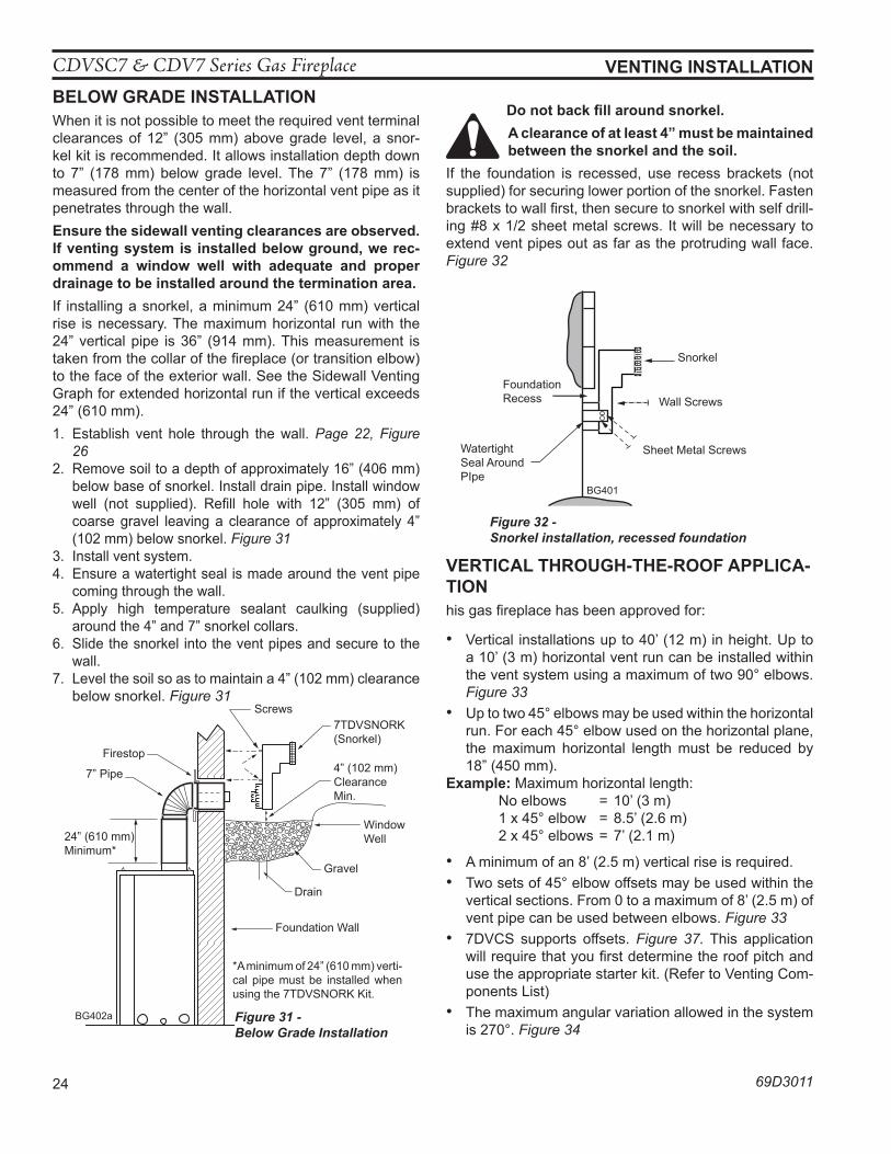
VenTInG InSTallaTIon Below GRaDe InSTallaTIonWhen it is not possible to meet the required vent terminal clearances of 12” (305 mm) above grade level, a snor-kel kit is recommended. It allows installation depth down to 7” (178 mm) below grade level. The 7” (178 mm) is measured from the center of the horizontal vent pipe as it penetrates through the wall.ensure the sidewall venting clearances are observed. If venting system is installed below ground, we rec-ommend a window well with adequate and proper drainage to be installed around the termination area.If installing a snorkel, a minimum 24” (610 mm) vertical rise is necessary. The maximum horizontal run with the 24” vertical pipe is 36” (914 mm). This measurement is taken from the collar of the fireplace (or transition elbow) to the face of the exterior wall. See the Sidewall Venting Graph for extended horizontal run if the vertical exceeds 24” (610 mm).1. Establish vent hole through the wall. Page 22, Figure
262. Remove soil to a depth of approximately 16” (406 mm)
below base of snorkel. Install drain pipe. Install window well (not supplied). Refill hole with 12” (305 mm) of coarse gravel leaving a clearance of approximately 4” (102 mm) below snorkel. Figure 31
3. Install vent system.4. Ensure a watertight seal is made around the vent pipe
coming through the wall.5. Apply high temperature sealant caulking (supplied)
around the 4” and 7” snorkel collars.6. Slide the snorkel into the vent pipes and secure to the
wall.7. Level the soil so as to maintain a 4” (102 mm) clearance
below snorkel. Figure 31
BG402aTop VentBelow grade installation1/26/00 djt
Firestop
7” Pipe
7TDVSNORK (Snorkel)
4” (102 mm) Clearance Min.
Window Well
Gravel
Drain
BG402a Figure 31 - Below Grade Installation
*A minimum of 24” (610 mm) verti-cal pipe must be installed when using the 7TDVSNORK Kit.
24” (610 mm) Minimum*
Screws
Foundation Wall
Do not back fill around snorkel.a clearance of at least 4” must be maintained between the snorkel and the soil.
If the foundation is recessed, use recess brackets (not supplied) for securing lower portion of the snorkel. Fasten brackets to wall first, then secure to snorkel with self drill-ing #8 x 1/2 sheet metal screws. It will be necessary to extend vent pipes out as far as the protruding wall face. Figure 32
BG401 �Snorkel �2/10/99 djt
Snorkel
Wall ScrewsFoundation Recess
Watertight Seal Around PIpe
Sheet Metal Screws
BG401
Figure 32 - Snorkel installation, recessed foundation
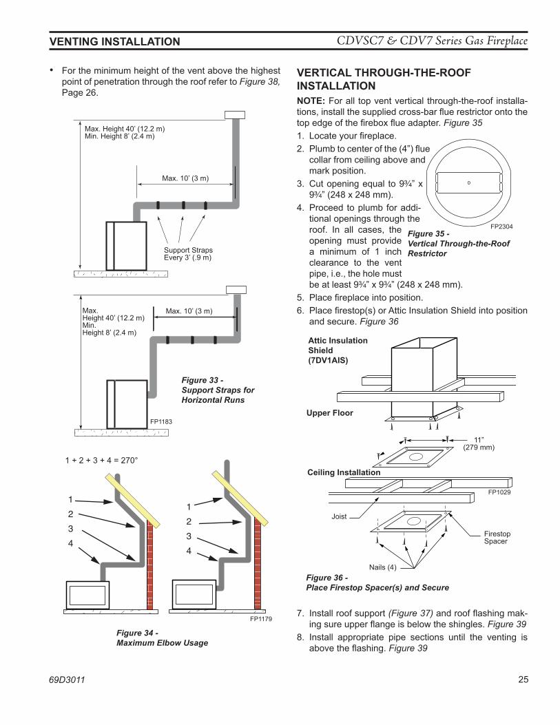
VeRTICal ThRouGh-The-RooF applICa-TIonhis gas fireplace has been approved for:
• Vertical installations up to 40’ (12 m) in height. Up to a 10’ (3 m) horizontal vent run can be installed within the vent system using a maximum of two 90° elbows. Figure 33
• Up to two 45° elbows may be used within the horizontal run. For each 45° elbow used on the horizontal plane, the maximum horizontal length must be reduced by 18” (450 mm).
example: Maximum horizontal length: No elbows = 10’ (3 m) 1 x 45° elbow = 8.5’ (2.6 m) 2 x 45° elbows = 7’ (2.1 m)
• A minimum of an 8’ (2.5 m) vertical rise is required.• Two sets of 45° elbow offsets may be used within the
vertical sections. From 0 to a maximum of 8’ (2.5 m) of vent pipe can be used between elbows. Figure 33
• 7DVCS supports offsets. Figure 37. This application will require that you first determine the roof pitch and use the appropriate starter kit. (Refer to Venting Com-ponents List)
• The maximum angular variation allowed in the system is 270°. Figure 34
CDVSC7 & CDV7 Series Gas Fireplace
69D3011 25
• For the minimum height of the vent above the highest point of penetration through the roof refer to Figure 38, Page 26.
Max. Height 40’ (12.2 m)Min. Height 8’ (2.4 m)
Max. 10’ (3 m)
Support Straps Every 3’ (.9 m)
Max. Height 40’ (12.2 m)Min. Height 8’ (2.4 m)
Max. 10’ (3 m)
FP1183
Figure 33 - Support Straps for Horizontal Runs
1234
1234
FP1179
Figure 34 - Maximum Elbow Usage
1 + 2 + 3 + 4 = 270°
VeRTICal ThRouGh-The-RooF InSTallaTIonnoTe: For all top vent vertical through-the-roof installa-tions, install the supplied cross-bar flue restrictor onto the top edge of the firebox flue adapter. Figure 351. Locate your fireplace.2. Plumb to center of the (4”) flue
collar from ceiling above and mark position.
3. Cut opening equal to 9C\v” x 9C\v” (248 x 248 mm).
4. Proceed to plumb for addi-tional openings through the roof. In all cases, the opening must provide a minimum of 1 inch clearance to the vent pipe, i.e., the hole must be at least 9C\v” x 9C\v” (248 x 248 mm).
5. Place fireplace into position.6. Place firestop(s) or Attic Insulation Shield into position
and secure. Figure 36
FP1029�attic insulation shieldfirestop spacers1/28/00 djt
attic Insulation Shield(7DV1aIS)
upper Floor
11”(279 mm)
Ceiling Installation
Joist
Firestop Spacer
Nails (4)
FP1029
Figure 36 - Place Firestop Spacer(s) and Secure
VenTInG InSTallaTIon
FP2304CDV7 top restrictor3/09
Figure 35 - Vertical Through-the-Roof Restrictor
FP2304
7. Install roof support (Figure 37) and roof flashing mak-ing sure upper flange is below the shingles. Figure 39
8. Install appropriate pipe sections until the venting is above the flashing. Figure 39
CDVSC7 & CDV7 Series Gas Fireplace
26 69D3011
VenTInG InSTallaTIon
FP1184Typical roof/ceilingsupport apps.
Typical Roof Support
applicationTypical Ceiling
Support application
FP1184
Figure 37 - Venting Supports
TWL101aTwist Lock Pipe2/8/99 djt
3 #5 Sheet Metal Screws per Joint
Sealant
Storm Collar
TWL101a
Figure 39 - Roof Flashing
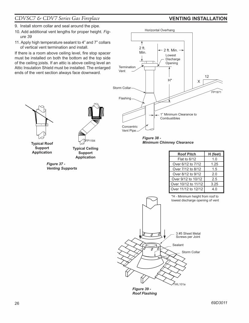
9. Install storm collar and seal around the pipe.10. Add additional vent lengths for proper height. Fig-
ure 3911. Apply high temperature sealant to 4” and 7” collars
of vertical vent termination and install.If there is a room above ceiling level, fire stop spacer must be installed on both the bottom ad the top side of the ceiling joists. If an attic is above ceiling level an Attic Insulation Shield must be installed. The enlarged ends of the vent section always face downward.
2 ft. Min.
2 ft. Min.
X12
H*
FP1971Min chimney clearance
Termination Vent
Storm Collar
Flashing
Lowest Discharge Opening
Concentric Vent Pipe
1” Minimum Clearance to Combustibles
FP1971
Horizontal Overhang
Figure 38 - Minimum Chimney Clearance
Roof pitch h (feet) Flat to 6/12 1.0 Over 6/12 to 7/12 1.25 Over 7/12 to 8/12 1.5 Over 8/12 to 9/12 2.0 Over 9/12 to 10/12 2.5 Over 10/12 to 11/12 3.25 Over 11/12 to 12/12 4.0
*H - Minimum height from roof to lowest discharge opening of vent
CDVSC7 & CDV7 Series Gas Fireplace
69D3011 27
FIReplaCe InSTallaTIon
CheCK GaS TypeUse proper gas type for the fireplace you are installing. If you have conflicting gas type, do not install fireplace. See dealer where you purchased the fireplace for proper fireplace for your gas type or con-version kit.
InSTall GaS pIpInG To FIReplaCe / BuRneR SySTeM loCaTIon
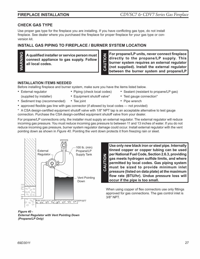
InSTallaTIon ITeMS neeDeDBefore installing fireplace and burner system, make sure you have the items listed below.• External regulator • Piping (check local codes) • Sealant (resistant to propane/LP gas) (supplied by installer) • Equipment shutoff valve* • Test gauge connection* • Sediment trap (recommended) • Tee joint • Pipe wrench• approved flexible gas line with gas connector (if allowed by local codes — not provided)* A CSA design-certified equipment shutoff valve with 1/8" NPT tap is an acceptable alternative to test gauge connection. Purchase the CSA design-certified equipment shutoff valve from your dealer.For propane/LP connections only, the installer must supply an external regulator. The external regulator will reduce incoming gas pressure. You must reduce incoming gas pressure to between 11 and 13 inches of water. If you do not reduce incoming gas pressure, burner system regulator damage could occur. Install external regulator with the vent pointing down as shown in Figure 40. Pointing the vent down protects it from freezing rain or sleet.
wa
Rn
InG a qualified installer or service person must
connect appliance to gas supply. Follow all local codes.
Ca
uTI
on For propane/lp units, never connect fireplace
directly to the propane/lp supply. This burner system requires an external regulator (not supplied). Install the external regulator between the burner system and propane/lp
FP1977external regulator
Figure 40 - External Regulator with Vent Pointing Down (Propane/LP Only)
FP1977
External Regulator
100 lb. (min) Propane/LP Supply Tank
Vent Pointing Down
Ca
uTI
on
use only new black iron or steel pipe. Internally tinned copper or copper tubing can be used per national Fuel Code, Section 2.6.3, providing gas meets hydrogen sulfide limits, and where permitted by local codes. Gas piping system must be sized to provide minimum inlet pressure (listed on data plate) at the maximum flow rate (BTu/hr). undue pressure loss will occur if the pipe is too small.
When using copper of flex connectors use only fittings approved for gas connections. The gas control inlet is 3/8" NPT.
CDVSC7 & CDV7 Series Gas Fireplace
28 69D3011
FIReplaCe InSTallaTIon
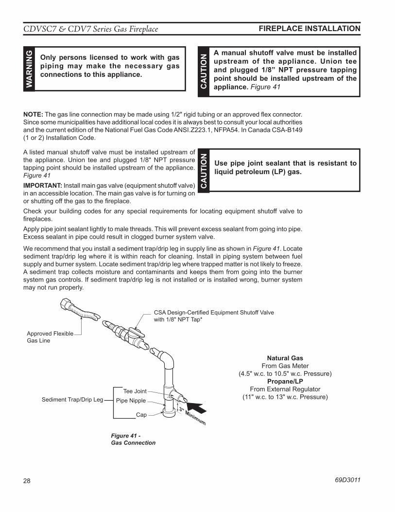
A listed manual shutoff valve must be installed upstream of the appliance. Union tee and plugged 1/8" NPT pressure tapping point should be installed upstream of the appliance. Figure 41IMpoRTanT: Install main gas valve (equipment shutoff valve) in an accessible location. The main gas valve is for turning on or shutting off the gas to the fireplace. Check your building codes for any special requirements for locating equipment shutoff valve to fireplaces.Apply pipe joint sealant lightly to male threads. This will prevent excess sealant from going into pipe. Excess sealant in pipe could result in clogged burner system valve.
We recommend that you install a sediment trap/drip leg in supply line as shown in Figure 41. Locate sediment trap/drip leg where it is within reach for cleaning. Install in piping system between fuel supply and burner system. Locate sediment trap/drip leg where trapped matter is not likely to freeze. A sediment trap collects moisture and contaminants and keeps them from going into the burner system gas controls. If sediment trap/drip leg is not installed or is installed wrong, burner system may not run properly.
noTe: The gas line connection may be made using 1/2" rigid tubing or an approved flex connector. Since some municipalities have additional local codes it is always best to consult your local authorities and the current edition of the National Fuel Gas Code ANSI.Z223.1, NFPA54. In Canada CSA-B149 (1 or 2) Installation Code.
wa
Rn
InG only persons licensed to work with gas
piping may make the necessary gas connections to this appliance.
Ca
uTI
on a manual shutoff valve must be installed
upstream of the appliance. union tee and plugged 1/8” npT pressure tapping point should be installed upstream of the appliance. Figure 41
Ca
uTI
on
use pipe joint sealant that is resistant to liquid petroleum (lp) gas.
3" Minimum
FP1978gas connection
Pipe Nipple
Cap
Figure 41 - Gas Connection
Tee Joint
Approved Flexible Gas Line
CSA Design-Certified Equipment Shutoff Valve with 1/8" NPT Tap*
Sediment Trap/Drip Leg
natural GasFrom Gas Meter
(4.5" w.c. to 10.5" w.c. Pressure)propane/lp
From External Regulator (11" w.c. to 13" w.c. Pressure)
CDVSC7 & CDV7 Series Gas Fireplace
69D3011 29
CheCK GaS pReSSuRe & eleCTRICal InSTallaTIon
1. Check gas type. The gas supply must be the same as stated on the appliance’s rating decal. If the gas supply is different from the fireplace, STop! Do not install the appliance. Contact your dealer immediately.
2. To ease installation, a 30" (mm) flex line with manual shut-off valve has been provided with this appliance. Install and attach 1/2" gas line onto shut-off valve.
3. After completing gas line connection, purge air from gas line and test all gas joints from the gas meter to the fireplace for leaks. Use a solution of 50/50 water and soap or a gas sniffer.
4. To adjust flame height, turn HI/LO knob to HI to get maximum pressure to burner. Turn HI/LO knob to LO to get minimum pressure.
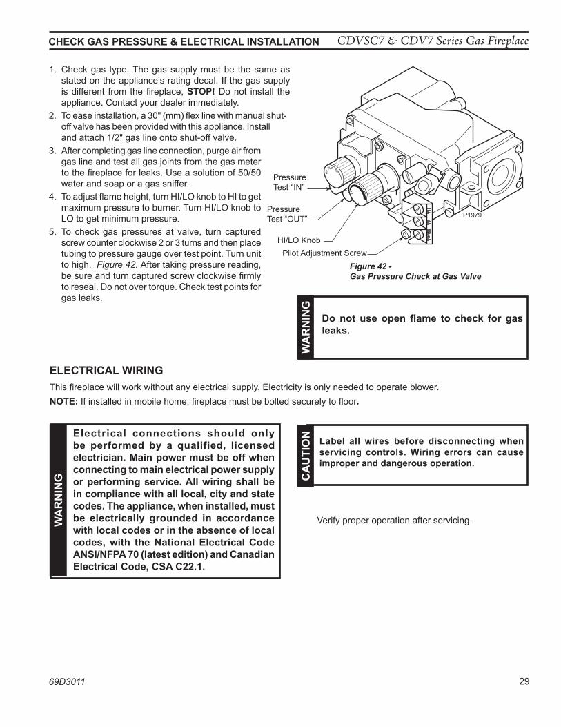
5. To check gas pressures at valve, turn captured screw counter clockwise 2 or 3 turns and then place tubing to pressure gauge over test point. Turn unit to high. Figure 42. After taking pressure reading, be sure and turn captured screw clockwise firmly to reseal. Do not over torque. Check test points for gas leaks.
FP1979Millivolt gas valve
FP1979
Figure 42 - Gas Pressure Check at Gas Valve
Pressure Test “IN”
Pressure Test “OUT”
HI/LO KnobPilot Adjustment Screw
eleCTRICal wIRInGThis fireplace will work without any electrical supply. Electricity is only needed to operate blower.noTe: If installed in mobile home, fireplace must be bolted securely to floor.
wa
Rn
InG
Do not use open flame to check for gas leaks.
wa
Rn
InG
electrical connections should only be performed by a qualified, licensed electrician. Main power must be off when connecting to main electrical power supply or performing service. all wiring shall be in compliance with all local, city and state codes. The appliance, when installed, must be electrically grounded in accordance with local codes or in the absence of local codes, with the national electrical Code anSI/nFpa 70 (latest edition) and Canadian electrical Code, CSa C22.1.
Ca
uTI
on label all wires before disconnecting when
servicing controls. wiring errors can cause improper and dangerous operation.
Verify proper operation after servicing.
CDVSC7 & CDV7 Series Gas Fireplace
30 69D3011
PILOT HI
LO
ON
OFF
FP2919DV wiring diagram
PiezoIgnitor
Thermocouple
SparkerThermopile
Pilot Assembly
Switch
ON OFF
Millivolt Valve
ON
OFF
Optional 15’Wall Switch
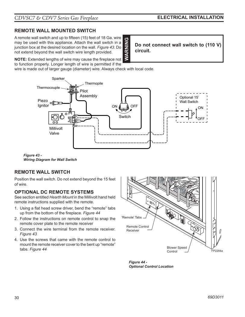
ReMoTe wall MounTeD SwITChA remote wall switch and up to fifteen (15) feet of 18 Ga. wire may be used with this appliance. Attach the wall switch in a junction box at the desired location on the wall. Figure 43. Do not extend beyond the wall switch wire length provided.
noTe: Extended lengths of wire may cause the fireplace not to function properly. Longer length of wire is permitted if the wire is made out of larger gauge (diameter) wire. Always check with local code.
Figure 43 - Wiring Diagram for Wall Switch
eleCTRICal InSTallaTIon
ReMoTe wall SwITChPosition the wall switch. Do not extend beyond the 15 feet of wire.
opTIonal DC ReMoTe SySTeMSSee section entitled Hearth Mount in the Millivolt hand held remote instructions supplied with the remote.1. Using a flat head screw driver, bend the “remote” tabs
up from the bottom of the fireplace. Figure 44 2. Follow the instructions on remote control to snap the
remote cover plate to the remote receiver3. Connect the wire terminal from the remote receiver.
Figure 434. Use the screws that came with the remote control to
mount the remote receiver cover to the bent up “remote” tabs. Figure 44
wa
Rn
InG
Do not connect wall switch to (110 V) circuit.
FP2284aCDV7 controls
Remote Control Receiver
Figure 44 - Optional Control Location
'Remote' Tabs
FP2284aBlower Speed Control
CDVSC7 & CDV7 Series Gas Fireplace
69D3011 31
eleCTRICal InSTallaTIon
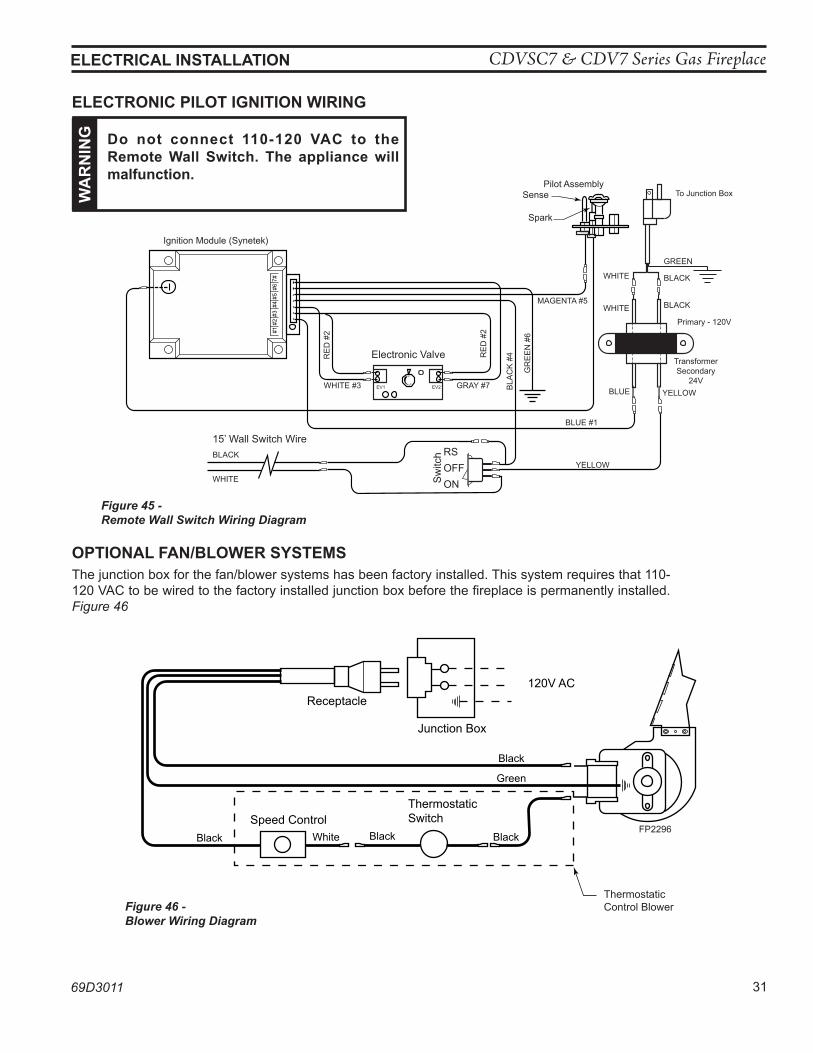
eleCTRonIC pIloT IGnITIon wIRInG
Figure 45 - Remote Wall Switch Wiring Diagram
#1#2
#3#4
#5#6
7#
Electronic Valve
GRAY #7
RE
D #
2
RE
D #
2
BLA
CK
#4
GR
EE
N #
6
BLUE #1
BLUE
YELLOW
YELLOWWHITE #3
MAGENTA #5
15’ Wall Switch Wire
BLACK
WHITE Sw
itch RS
OFF
ON
TransformerSecondary
24V
WHITE
WHITE
GREEN
BLACK
BLACK
Primary - 120V
To Junction BoxPilot Assembly
Sense
Ignition Module (Synetek)
Spark
FP2295electronic wiring diagram
HI
LO
EV1 EV2
wa
Rn
InG Do not connect 110-120 VaC to the
Remote wall Switch. The appliance will malfunction.
opTIonal Fan/BloweR SySTeMSThe junction box for the fan/blower systems has been factory installed. This system requires that 110-120 VAC to be wired to the factory installed junction box before the fireplace is permanently installed. Figure 46
BlackBlack
Green
Black
Black White
ThermostaticSwitch
Receptacle
Junction Box
120V AC
FP2296blower wiring
Speed Control
Thermostatic Control Blower
FP2296
Figure 46 -Blower Wiring Diagram
CDVSC7 & CDV7 Series Gas Fireplace
32 69D3011
MIllIVolT opeRaTInG InSTRuCTIonS
a. This appliance is equipped with a pilot which must be lit with built-in piezo ignitor while following these instructions exactly.
B. BEFORE OPERATING smell all around the appliance area for gas. Be sure to smell next to the floor because some gas is heavier than air and will settle on the floor.
whaT To Do IF you SMell GaS: • Turn off all gas to the appliance. • Open windows. • Do not attempt to light any appliance. • Do not touch any electric switch; do not use any phone in your building. • Immediately call your gas supplier from a neighbor's phone. Follow the gas supplier's instruc-
tions. • If you cannot reach your gas supplier, call the fire department.C. Use only your hand to push in, or turn the gas control knob. Never use tools. If the knob will not
push in or turn by hand, don't try to repair it. Call a qualified service technician. Force or attempted repair may result in a fire or explosion.
D. Do not use this appliance if any part of it has been under water. Immediately call a qualified service technician to inspect the appliance and to replace any part of the control system and any gas control that has been under water.
FoR youR SaFeTy ReaD BeFoRe lIGhTInG
lIGhTInG pIloT FoR The FIRST TIMe InITIal lIGhTInG Purge air from the supply line as follows:
• Open main shutoff valve. • Unscrew main pressure test point. • Leave inlet test screw open until gas comes in. • When gas is flowing, tighten inlet screw immedi-
ately. leaK TeSTInG
1. Follow the pipe from the gas supply line connection to the gas valve. Check connection for leaks with soap and water mixture.
2. Next check for gas leaks at the burner with soap and water mixture.3. Check the pilot for gas leaks with soap and water mixture.
wa
Rn
InG If you do not follow these instruction
exactly, a fire or explosion may result causing property damage, personal injury or loss of life.
wa
Rn
InG never use an open flame to check for
gas leak.
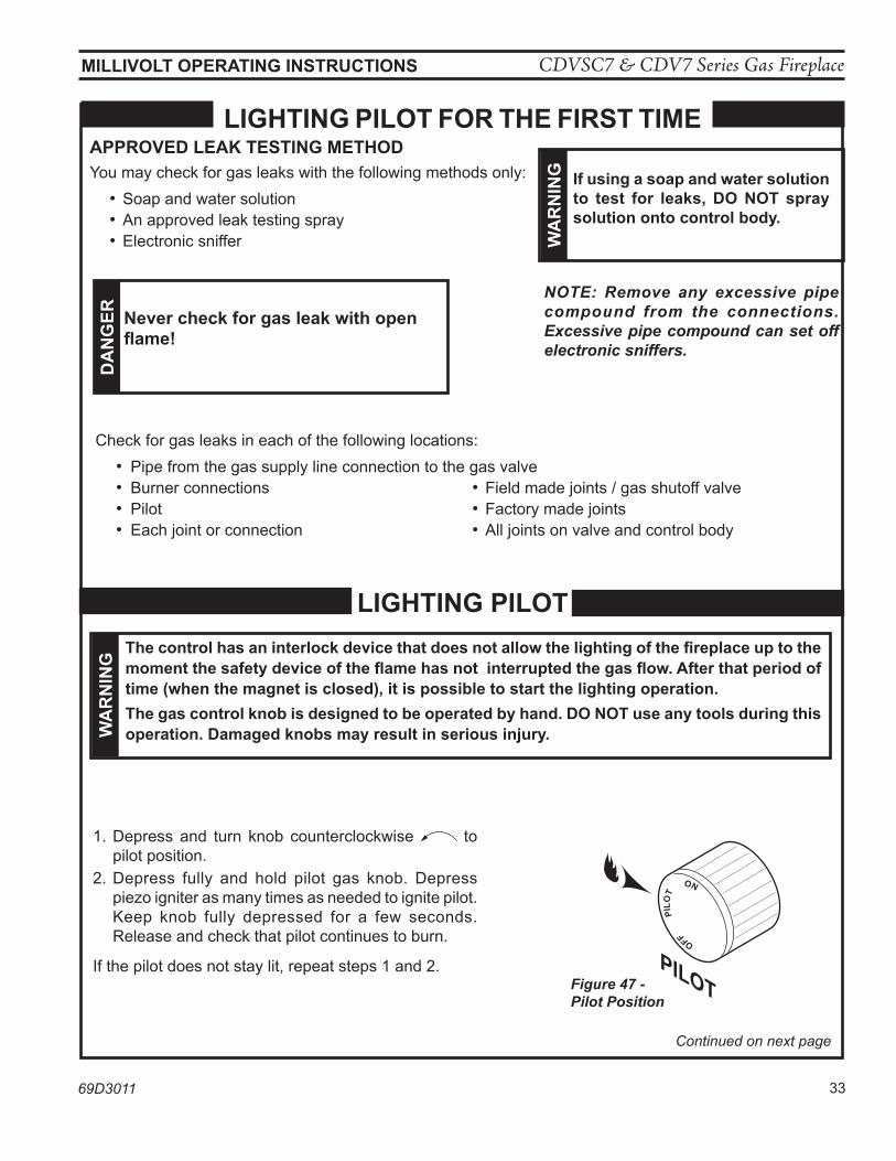
CDVSC7 & CDV7 Series Gas Fireplace
69D3011 33
MIllIVolT opeRaTInG InSTRuCTIonS
PILOT
OFF
P
ILO
T
ON
FP1935control knob pilot
Continued on next page
appRoVeD leaK TeSTInG MeThoD You may check for gas leaks with the following methods only:
• Soap and water solution• An approved leak testing spray• Electronic sniffer
NOTE: Remove any excessive pipe compound from the connections. Excessive pipe compound can set off electronic sniffers.
1. Depress and turn knob counterclockwise to pilot position.
2. Depress fully and hold pilot gas knob. Depress piezo igniter as many times as needed to ignite pilot. Keep knob fully depressed for a few seconds. Release and check that pilot continues to burn.
If the pilot does not stay lit, repeat steps 1 and 2.
lIGhTInG pIloT
Figure 47 - Pilot Position
Check for gas leaks in each of the following locations: • Pipe from the gas supply line connection to the gas valve • Burner connections • Field made joints / gas shutoff valve • Pilot • Factory made joints • Each joint or connection • All joints on valve and control body
lIGhTInG pIloT FoR The FIRST TIMe
wa
Rn
InG If using a soap and water solution
to test for leaks, Do noT spray solution onto control body.
Da
nG
eR never check for gas leak with open flame!
wa
Rn
InG
The control has an interlock device that does not allow the lighting of the fireplace up to the moment the safety device of the flame has not interrupted the gas flow. after that period of time (when the magnet is closed), it is possible to start the lighting operation. The gas control knob is designed to be operated by hand. Do noT use any tools during this operation. Damaged knobs may result in serious injury.
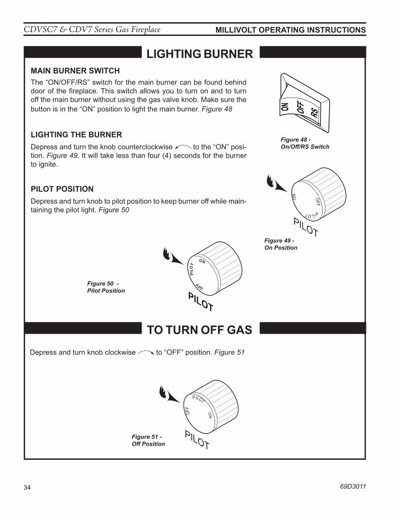
CDVSC7 & CDV7 Series Gas Fireplace
34 69D3011
MIllIVolT opeRaTInG InSTRuCTIonS
PILOT
OFF
PILOT
ON
OFFPILOT
ON
PILOT
FP1937control knob on
Figure 49 - On Position
PILOT
OFF
P
ILO
T
ON
FP1935control knob pilot
Figure 48 - On/Off/RS Switch
OFFON
RS
lIGhTInG BuRneR MaIn BuRneR SwITCh The “ON/OFF/RS” switch for the main burner can be found behind door of the fireplace. This switch allows you to turn on and to turn off the main burner without using the gas valve knob. Make sure the button is in the “ON” position to light the main burner. Figure 48
lIGhTInG The BuRneRDepress and turn the knob counterclockwise to the “ON” posi-tion. Figure 49. It will take less than four (4) seconds for the burner to ignite.
pIloT poSITIonDepress and turn knob to pilot position to keep burner off while main-taining the pilot light. Figure 50
Depress and turn knob clockwise to “OFF” position. Figure 51
To TuRn oFF GaS
Figure 51 - Off Position
Figure 50 - Pilot Position
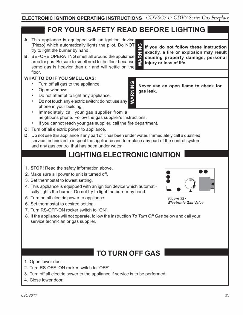
CDVSC7 & CDV7 Series Gas Fireplace
69D3011 35
eleCTRonIC IGnITIon opeRaTInG InSTRuCTIonS
a. This appliance is equipped with an ignition device (Piezo) which automatically lights the pilot. Do NOT try to light the burner by hand.
B. BEFORE OPERATING smell all around the appliance area for gas. Be sure to smell next to the floor because some gas is heavier than air and will settle on the floor.
whaT To Do IF you SMell GaS: • Turn off all gas to the appliance. • Open windows. • Do not attempt to light any appliance. • Do not touch any electric switch; do not use any
phone in your building. • Immediately call your gas supplier from a
neighbor's phone. Follow the gas supplier's instructions. • If you cannot reach your gas supplier, call the fire department.C. Turn off all electric power to appliance. D. Do not use this appliance if any part of it has been under water. Immediately call a qualified
service technician to inspect the appliance and to replace any part of the control system and any gas control that has been under water.
lIGhTInG eleCTRonIC IGnITIon
FoR youR SaFeTy ReaD BeFoRe lIGhTInG
To TuRn oFF GaS 1. Open lower door.2. Turn RS-OFF_ON rocker switch to “OFF”.3. Turn off all electric power to the appliance if service is to be performed.4. Close lower door.
1. STop! Read the safety information above.2. Make sure all power to unit is turned off. 3. Set thermostat to lowest setting.4. This appliance is equipped with an ignition device which automati-
cally lights the burner. Do not try to light the burner by hand. 5. Turn on all electric power to appliance.6. Set thermostat to desired setting.7. Turn RS-OFF-ON rocker switch to “ON”. 8. If the appliance will not operate, follow the instruction To Turn Off Gas below and call your
service technician or gas supplier.
LO
HI
FP2102BDV electronic valve
Figure 52 - Electronic Gas Valve
wa
Rn
InG If you do not follow these instruction
exactly, a fire or explosion may result causing property damage, personal injury or loss of life.
wa
Rn
InG never use an open flame to check for
gas leak.
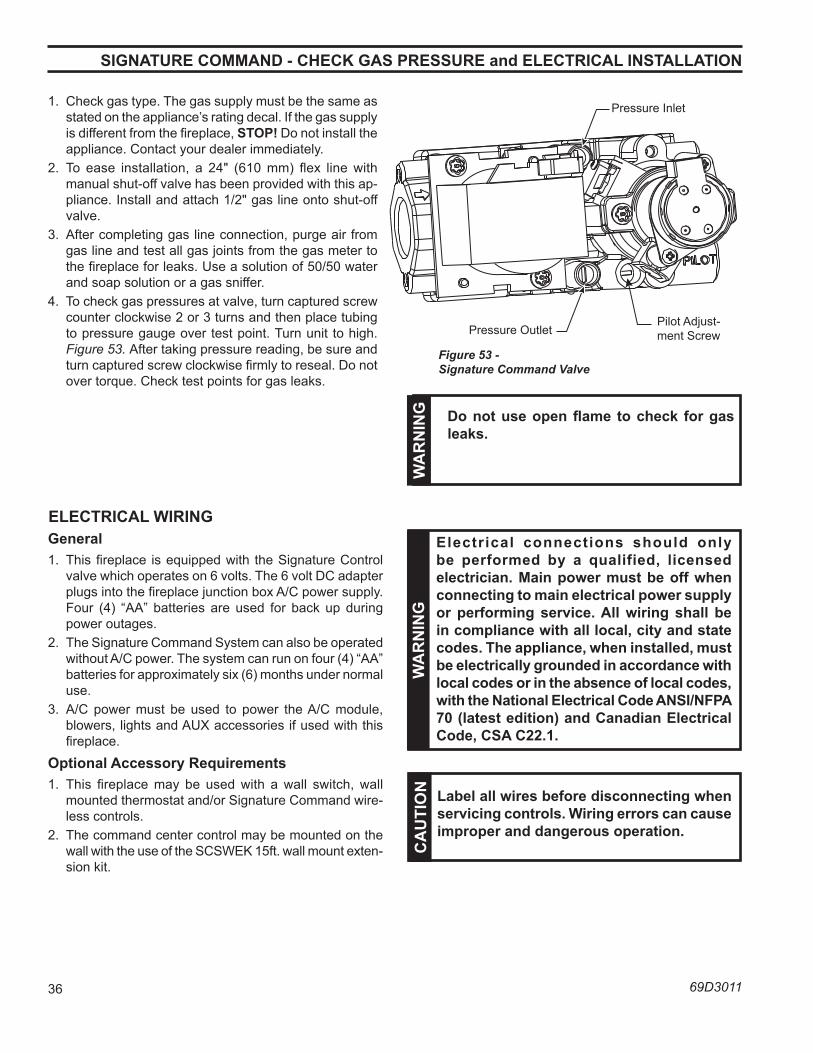
CDVSC7 & CDV7 Series Gas Fireplace
36 69D3011
SIGnaTuRe CoMManD - CheCK GaS pReSSuRe and eleCTRICal InSTallaTIon
1. Check gas type. The gas supply must be the same as stated on the appliance’s rating decal. If the gas supply is different from the fireplace, STop! Do not install the appliance. Contact your dealer immediately.
2. To ease installation, a 24" (610 mm) flex line with manual shut-off valve has been provided with this ap-pliance. Install and attach 1/2" gas line onto shut-off valve.
3. After completing gas line connection, purge air from gas line and test all gas joints from the gas meter to the fireplace for leaks. Use a solution of 50/50 water and soap solution or a gas sniffer.
4. To check gas pressures at valve, turn captured screw counter clockwise 2 or 3 turns and then place tubing to pressure gauge over test point. Turn unit to high. Figure 53. After taking pressure reading, be sure and turn captured screw clockwise firmly to reseal. Do not over torque. Check test points for gas leaks.
Figure 53 - Signature Command Valve
FP1909asignature command valvealternate view8/08
Pressure Inlet
Pilot Adjust-ment ScrewPressure Outlet
wa
Rn
InG Do not use open flame to check for gas
leaks.
eleCTRICal wIRInGGeneral1. This fireplace is equipped with the Signature Control
valve which operates on 6 volts. The 6 volt DC adapter plugs into the fireplace junction box A/C power supply. Four (4) “AA” batteries are used for back up during power outages.
2. The Signature Command System can also be operated without A/C power. The system can run on four (4) “AA” batteries for approximately six (6) months under normal use.
3. A/C power must be used to power the A/C module, blowers, lights and AUX accessories if used with this fireplace.
optional accessory Requirements1. This fireplace may be used with a wall switch, wall
mounted thermostat and/or Signature Command wire-less controls.
2. The command center control may be mounted on the wall with the use of the SCSWEK 15ft. wall mount exten-sion kit.
wa
Rn
InG
e lectrical connections should only be performed by a qualified, licensed electrician. Main power must be off when connecting to main electrical power supply or performing service. all wiring shall be in compliance with all local, city and state codes. The appliance, when installed, must be electrically grounded in accordance with local codes or in the absence of local codes, with the national electrical Code anSI/nFpa 70 (latest edition) and Canadian electrical Code, CSa C22.1.
Ca
uTI
on label all wires before disconnecting when
servicing controls. wiring errors can cause improper and dangerous operation.
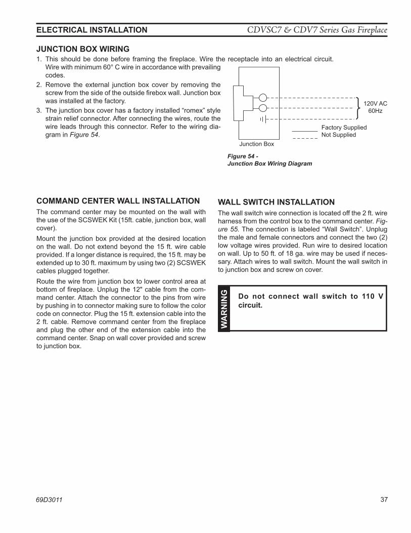
CDVSC7 & CDV7 Series Gas Fireplace
69D3011 37
junCTIon Box wIRInG1. This should be done before framing the fireplace. Wire the receptacle into an electrical circuit.
Wire with minimum 60° C wire in accordance with prevailing codes.
2. Remove the external junction box cover by removing the screw from the side of the outside firebox wall. Junction box was installed at the factory.
3. The junction box cover has a factory installed “romex” style strain relief connector. After connecting the wires, route the wire leads through this connector. Refer to the wiring dia-gram in Figure 54.
Figure 54 - Junction Box Wiring Diagram
FP1912Junction box wiring8/08
Junction Box
Factory SuppliedNot Supplied
120V AC60Hz
eleCTRICal InSTallaTIon
CoMManD CenTeR wall InSTallaTIonThe command center may be mounted on the wall with the use of the SCSWEK Kit (15ft. cable, junction box, wall cover).Mount the junction box provided at the desired location on the wall. Do not extend beyond the 15 ft. wire cable provided. If a longer distance is required, the 15 ft. may be extended up to 30 ft. maximum by using two (2) SCSWEK cables plugged together.Route the wire from junction box to lower control area at bottom of fireplace. Unplug the 12" cable from the com-mand center. Attach the connector to the pins from wire by pushing in to connector making sure to follow the color code on connector. Plug the 15 ft. extension cable into the 2 ft. cable. Remove command center from the fireplace and plug the other end of the extension cable into the command center. Snap on wall cover provided and screw to junction box.
wall SwITCh InSTallaTIonThe wall switch wire connection is located off the 2 ft. wire harness from the control box to the command center. Fig-ure 55. The connection is labeled “Wall Switch”. Unplug the male and female connectors and connect the two (2) low voltage wires provided. Run wire to desired location on wall. Up to 50 ft. of 18 ga. wire may be used if neces-sary. Attach wires to wall switch. Mount the wall switch in to junction box and screw on cover.
wa
Rn
InG Do not connect wall switch to 110 V circuit.
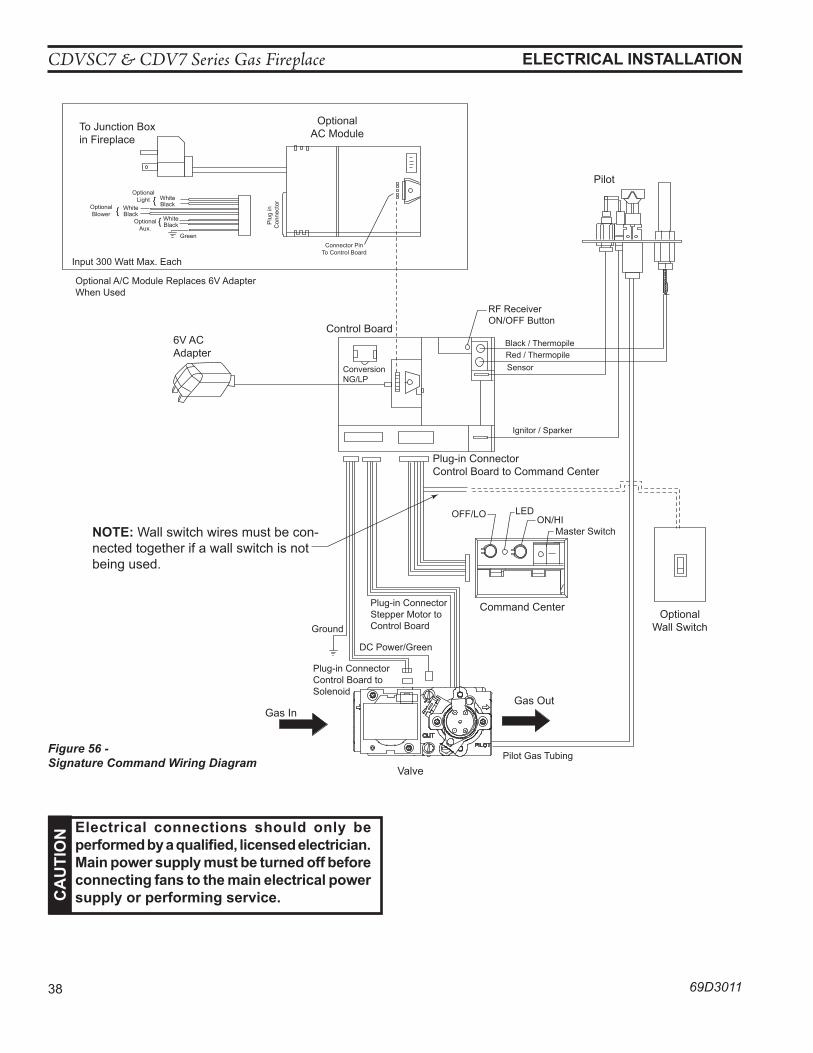
CDVSC7 & CDV7 Series Gas Fireplace
38 69D3011
To Junction Boxin Fireplace
OptionalAC Module
{ WhiteBlack
OptionalLight
WhiteBlack{Optional
BlowerWhiteBlack{Optional
Aux.Green
Plu
g in
C
onne
ctor
Connector PinTo Control Board
Input 300 Watt Max. Each
Optional A/C Module Replaces 6V AdapterWhen Used
6V ACAdapter
Control Board
RF ReceiverON/OFF Button
Pilot
Black / ThermopileRed / Thermopile
Sensor
Ignitor / Sparker
ConversionNG/LP
Plug-in ConnectorControl Board to Command Center
OFF/LO LEDON/HI
Master Switch
Command CenterOptional
Wall Switch
Plug-in ConnectorStepper Motor toControl Board
DC Power/Green
Ground
Plug-in ConnectorControl Board toSolenoid
Gas InGas Out
Pilot Gas Tubing
Valve
eleCTRICal InSTallaTIonC
au
TIo
n electrical connections should only be performed by a qualified, licensed electrician. Main power supply must be turned off before connecting fans to the main electrical power supply or performing service.
Figure 56 -Signature Command Wiring Diagram
noTe: Wall switch wires must be con-nected together if a wall switch is not being used.
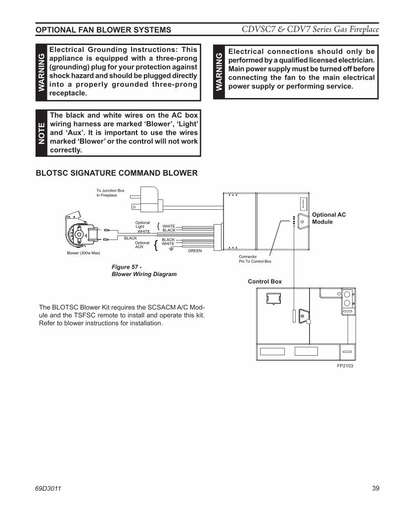
CDVSC7 & CDV7 Series Gas Fireplace
69D3011 39
To Junction BoxIn Fireplace
WHITEBLACKWHITE
BLACK BLACKWHITE
GREEN
ConnectorPin To Contro l Box
{
{
OptionalLight
OptionalAUX
Blower (300w Max)
FP2103AC fan wiring
Figure 57 -Blower Wiring Diagram
FP2103
Control Box
optional aC Module
opTIonal Fan BloweR SySTeMSn
oTe
The black and white wires on the aC box wiring harness are marked ‘Blower’, ‘light’ and ‘aux’. It is important to use the wires marked ‘Blower’ or the control will not work correctly.
wa
Rn
InG electrical connections should only be
performed by a qualified licensed electrician. Main power supply must be turned off before connecting the fan to the main electrical power supply or performing service.
BloTSC SIGnaTuRe CoMManD BloweR
electrical Grounding Instructions: This appliance is equipped with a three-prong (grounding) plug for your protection against shock hazard and should be plugged directly into a properly grounded three-prong receptacle.w
aR
nIn
G
The BLOTSC Blower Kit requires the SCSACM A/C Mod-ule and the TSFSC remote to install and operate this kit. Refer to blower instructions for installation.
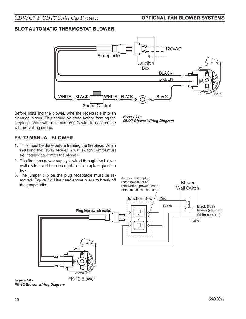
CDVSC7 & CDV7 Series Gas Fireplace
40 69D3011
opTIonal Fan BloweR SySTeMS
BloT auToMaTIC TheRMoSTaT BloweR
Figure 58 - BLOT Blower Wiring Diagram
BLACKBLACKWHITE
GREEN
BLACK
BLACKWHITE
Receptacle
Junction Box
120VAC
Speed Control
FP2675BLOT blower wiring
FP2675
Before installing the blower, wire the receptacle into an electrical circuit. This should be done before framing the fireplace. Wire with minimum 60° C wire in accordance with prevailing codes.
FK-12 Manual BloweR1. This must be done before framing the fireplace. When
installing the FK-12 blower, a wall switch control must be installed to control the blower.
2. The fireplace power supply is wired through the blower wall switch and then brought to the fireplace junction box.
3. The jumper clip on the plug receptacle must be re-moved. Figure 59. Use needlenose pliers to break off the jumper clip.
Junction Box
BlowerWall Switch
Black (live)Green (ground)White (neutral)
Red
Black
FK-12 Blower
Plug into switch outlet
FP2676FK12 wiring
Jumper clip on plug receptacle must be removed on power side to make outlet switchable
Figure 59 - FK-12 Blower wiring Diagram
FP2676
CDVSC7 & CDV7 Series Gas Fireplace
69D3011 41
opeRaTInG InSTRuCTIonS - SIGnaTuRe CoMManD
a. This appliance is equipped with an ignition device which automatically lights the pilot. Refer to the instructions.
B. BEFORE OPERATING smell all around the appliance area for gas. Be sure to smell next to the floor because some gas is heavier than air and will settle on the floor.
whaT To Do IF you SMell GaS: • Do not attempt to light any appliance. • Do not touch any electric switch; do not use any phone in your building. • Immediately call your gas supplier from a neighbor's phone. Follow the gas supplier's instruc-
tions. • If you cannot reach your gas supplier, call the fire department.
C. Use only your finger to push in the master switch. Never use tools. If the switch will not function by hand, do not try to repair it. Call a qualified service technician. Force or attempted repair may result in a fire or explosion.
D. Do not use this appliance if any part of it has been under water. Immediately call a qualified service technician to inspect the appliance and to replace any part of the control system and any gas control that has been under water.
FoR youR SaFeTy ReaD BeFoRe lIGhTInG
continued on next page
wa
Rn
InG If you do not follow these instructions
exactly, a fire or explosion may result causing property damage, personal injury or loss of lie.
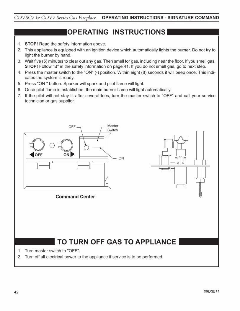
CDVSC7 & CDV7 Series Gas Fireplace
42 69D3011
opeRaTInG InSTRuCTIonS
opeRaTInG InSTRuCTIonS - SIGnaTuRe CoMManD
1. STop! Read the safety information above.2. This appliance is equipped with an ignition device which automatically lights the burner. Do not try to
light the burner by hand.3. Wait five (5) minutes to clear out any gas. Then smell for gas, including near the floor. If you smell gas,
STop! Follow "B" in the safety information on page 41. If you do not smell gas, go to next step.4. Press the master switch to the "ON" (-) position. Within eight (8) seconds it will beep once. This indi-
cates the system is ready.5. Press "ON " button. Sparker will spark and pilot flame will light. 6. Once pilot flame is established, the main burner flame will light automatically.7. If the pilot will not stay lit after several tries, turn the master switch to "OFF" and call your service
technician or gas supplier.
To TuRn oFF GaS To applIanCe1. Turn master switch to "OFF".2. Turn off all electrical power to the appliance if service is to be performed.
FP1913Switch box 8/08
Command Center
ON
Master Switch
OFF
FP1914Pilot w sparker 8/08
oFF on
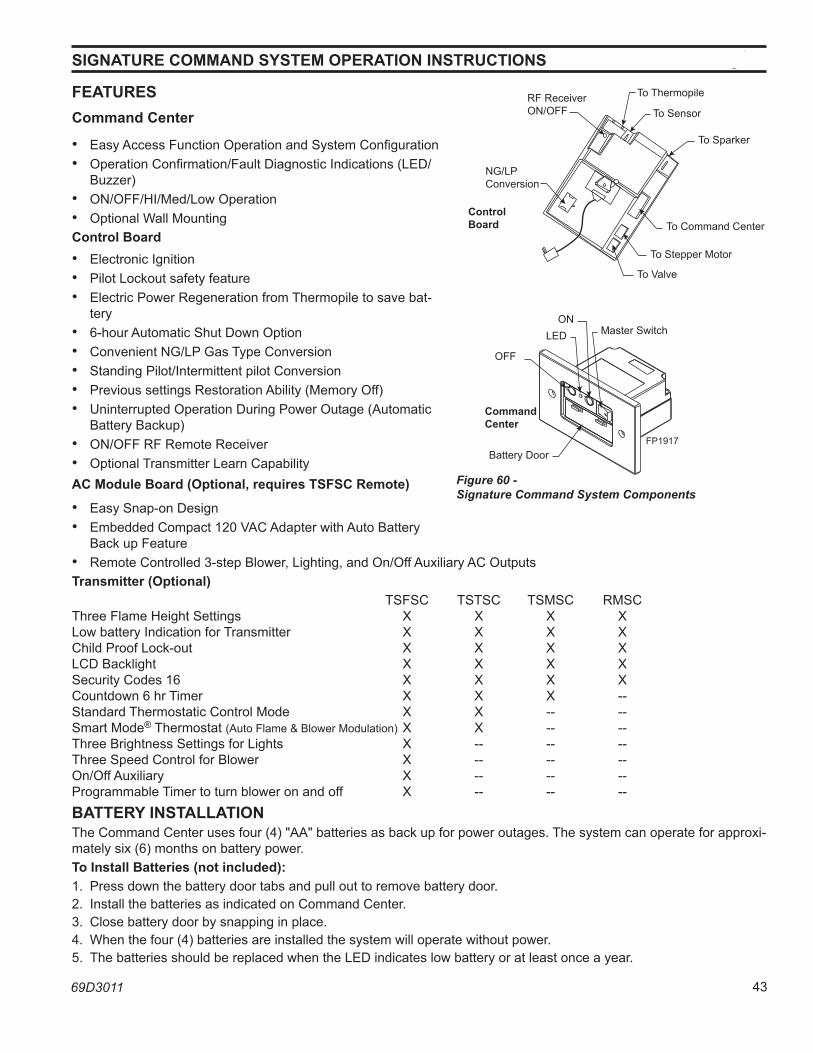
CDVSC7 & CDV7 Series Gas Fireplace
69D3011 43
FeaTuReSCommand Center
• Easy Access Function Operation and System Configuration• Operation Confirmation/Fault Diagnostic Indications (LED/
Buzzer)• ON/OFF/HI/Med/Low Operation• Optional Wall MountingControl Board• Electronic Ignition• Pilot Lockout safety feature• Electric Power Regeneration from Thermopile to save bat-
tery• 6-hour Automatic Shut Down Option• Convenient NG/LP Gas Type Conversion• Standing Pilot/Intermittent pilot Conversion• Previous settings Restoration Ability (Memory Off)• Uninterrupted Operation During Power Outage (Automatic
Battery Backup)• ON/OFF RF Remote Receiver• Optional Transmitter Learn CapabilityaC Module Board (optional, requires TSFSC Remote)
• Easy Snap-on Design• Embedded Compact 120 VAC Adapter with Auto Battery
Back up Feature• Remote Controlled 3-step Blower, Lighting, and On/Off Auxiliary AC OutputsTransmitter (optional) TSFSC TSTSC TSMSC RMSCThree Flame Height Settings X X X XLow battery Indication for Transmitter X X X XChild Proof Lock-out X X X XLCD Backlight X X X XSecurity Codes 16 X X X XCountdown 6 hr Timer X X X --Standard Thermostatic Control Mode X X -- --Smart Mode® Thermostat (Auto Flame & Blower Modulation) X X -- --Three Brightness Settings for Lights X -- -- --Three Speed Control for Blower X -- -- --On/Off Auxiliary X -- -- --Programmable Timer to turn blower on and off X -- -- --BaTTeRy InSTallaTIonThe Command Center uses four (4) "AA" batteries as back up for power outages. The system can operate for approxi-mately six (6) months on battery power.To Install Batteries (not included):1. Press down the battery door tabs and pull out to remove battery door.2. Install the batteries as indicated on Command Center.3. Close battery door by snapping in place.4. When the four (4) batteries are installed the system will operate without power.5. The batteries should be replaced when the LED indicates low battery or at least once a year.
SIGnaTuRe CoMManD SySTeM opeRaTIon InSTRuCTIonS
FP1917Signature components8/08
RF ReceiverON/OFF
NG/LP Conversion
To Thermopile
To Sensor
To Sparker
To Command Center
To Stepper Motor
To Valve
Battery Door
Master SwitchON
LED
OFF
Control Board
Command Center
Figure 60 - Signature Command System Components
FP1917
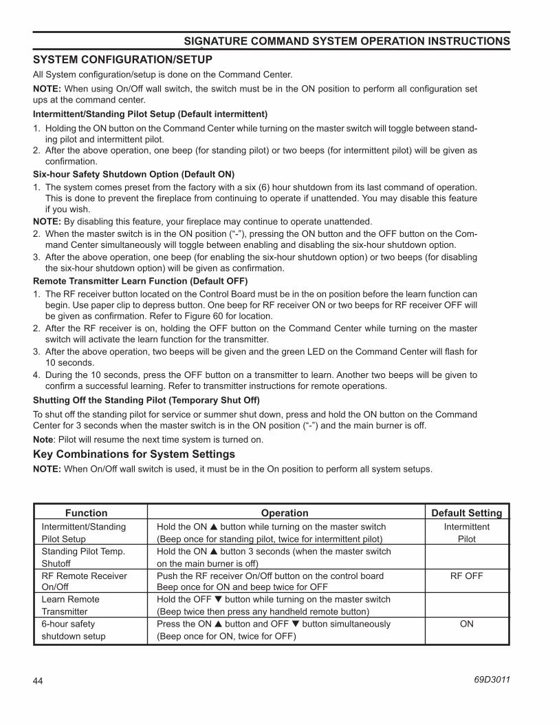
CDVSC7 & CDV7 Series Gas Fireplace
44 69D3011
SySTeM ConFIGuRaTIon/SeTupAll System configuration/setup is done on the Command Center.noTe: When using On/Off wall switch, the switch must be in the ON position to perform all configuration set ups at the command center.Intermittent/Standing pilot Setup (Default intermittent)1. Holding the ON button on the Command Center while turning on the master switch will toggle between stand-
ing pilot and intermittent pilot. 2. After the above operation, one beep (for standing pilot) or two beeps (for intermittent pilot) will be given as
confirmation.Six-hour Safety Shutdown option (Default on)1. The system comes preset from the factory with a six (6) hour shutdown from its last command of operation.
This is done to prevent the fireplace from continuing to operate if unattended. You may disable this feature if you wish.
noTe: By disabling this feature, your fireplace may continue to operate unattended.2. When the master switch is in the ON position (“-”), pressing the ON button and the OFF button on the Com-
mand Center simultaneously will toggle between enabling and disabling the six-hour shutdown option. 3. After the above operation, one beep (for enabling the six-hour shutdown option) or two beeps (for disabling
the six-hour shutdown option) will be given as confirmation.Remote Transmitter learn Function (Default oFF)1. The RF receiver button located on the Control Board must be in the on position before the learn function can
begin. Use paper clip to depress button. One beep for RF receiver ON or two beeps for RF receiver OFF will be given as confirmation. Refer to Figure 60 for location.
2. After the RF receiver is on, holding the OFF button on the Command Center while turning on the master switch will activate the learn function for the transmitter.
3. After the above operation, two beeps will be given and the green LED on the Command Center will flash for 10 seconds.
4. During the 10 seconds, press the OFF button on a transmitter to learn. Another two beeps will be given to confirm a successful learning. Refer to transmitter instructions for remote operations.
Shutting off the Standing pilot (Temporary Shut off)To shut off the standing pilot for service or summer shut down, press and hold the ON button on the Command Center for 3 seconds when the master switch is in the ON position (“-”) and the main burner is off.note: Pilot will resume the next time system is turned on.Key Combinations for System SettingsnoTe: When On/Off wall switch is used, it must be in the On position to perform all system setups.
SIGnaTuRe CoMManD SySTeM opeRaTIon InSTRuCTIonS
Function operation Default Setting Intermittent/Standing Hold the ON ▲ button while turning on the master switch Intermittent Pilot Setup (Beep once for standing pilot, twice for intermittent pilot) Pilot Standing Pilot Temp. Hold the ON ▲ button 3 seconds (when the master switch Shutoff on the main burner is off) RF Remote Receiver Push the RF receiver On/Off button on the control board RF OFF On/Off Beep once for ON and beep twice for OFF Learn Remote Hold the OFF ▼ button while turning on the master switch Transmitter (Beep twice then press any handheld remote button) 6-hour safety Press the ON ▲ button and OFF ▼ button simultaneously ON shutdown setup (Beep once for ON, twice for OFF)
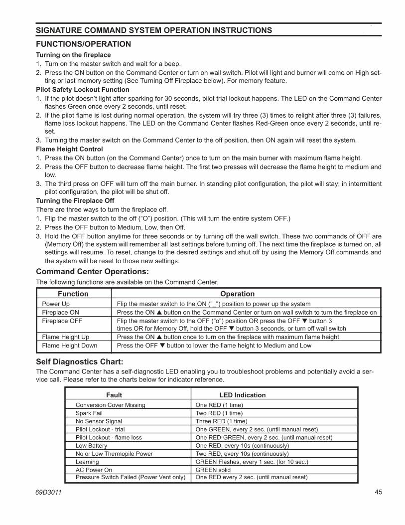
CDVSC7 & CDV7 Series Gas Fireplace
69D3011 45
SIGnaTuRe CoMManD SySTeM opeRaTIon InSTRuCTIonSFunCTIonS/opeRaTIonTurning on the fireplace1. Turn on the master switch and wait for a beep.2. Press the ON button on the Command Center or turn on wall switch. Pilot will light and burner will come on High set-
ting or last memory setting (See Turning Off Fireplace below). For memory feature.pilot Safety lockout Function1. If the pilot doesn’t light after sparking for 30 seconds, pilot trial lockout happens. The LED on the Command Center
flashes Green once every 2 seconds, until reset.2. If the pilot flame is lost during normal operation, the system will try three (3) times to relight after three (3) failures,
flame loss lockout happens. The LED on the Command Center flashes Red-Green once every 2 seconds, until re-set.
3. Turning the master switch on the Command Center to the off position, then ON again will reset the system. Flame height Control 1. Press the ON button (on the Command Center) once to turn on the main burner with maximum flame height. 2. Press the OFF button to decrease flame height. The first two presses will decrease the flame height to medium and
low. 3. The third press on OFF will turn off the main burner. In standing pilot configuration, the pilot will stay; in intermittent
pilot configuration, the pilot will be shut off.Turning the Fireplace offThere are three ways to turn the fireplace off.1. Flip the master switch to the off (“O”) position. (This will turn the entire system OFF.)2. Press the OFF button to Medium, Low, then Off.3. Hold the OFF button anytime for three seconds or by turning off the wall switch. These two commands of OFF are
(Memory Off) the system will remember all last settings before turning off. The next time the fireplace is turned on, all settings will resume. To reset, change to the desired settings and shut off by using the Memory Off commands and the system will be reset to those new settings.
Command Center operations:The following functions are available on the Command Center.
Fault leD Indication Conversion Cover Missing One RED (1 time) Spark Fail Two RED (1 time) No Sensor Signal Three RED (1 time) Pilot Lockout - trial One GREEN, every 2 sec. (until manual reset) Pilot Lockout - flame loss One RED-GREEN, every 2 sec. (until manual reset) Low Battery One RED, every 10s (continuously) No or Low Thermopile Power Two RED, every 10s (continuously) Learning GREEN Flashes, every 1 sec. (for 10 sec.) AC Power On GREEN solid Pressure Switch Failed (Power Vent only) One RED every 2 sec. (until manual reset)
Self Diagnostics Chart:The Command Center has a self-diagnostic LED enabling you to troubleshoot problems and potentially avoid a ser-vice call. Please refer to the charts below for indicator reference.
Function operation Power Up Flip the master switch to the ON ("_") position to power up the system Fireplace ON Press the ON ▲ button on the Command Center or turn on wall switch to turn the fireplace on Fireplace OFF Flip the master switch to the OFF ("o") position OR press the OFF ▼ button 3 times OR for Memory Off, hold the OFF ▼ button 3 seconds, or turn off wall switch Flame Height Up Press the ON ▲ button once to turn on the fireplace with maximum flame height Flame Height Down Press the OFF ▼ button to lower the flame height to Medium and Low
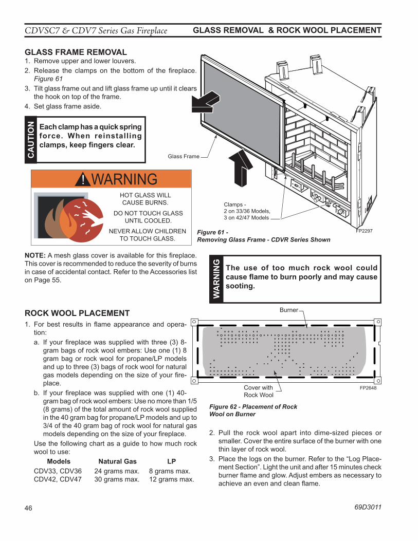
CDVSC7 & CDV7 Series Gas Fireplace
46 69D3011
GlaSS ReMoVal & RoCK wool plaCeMenT
GlaSS FRaMe ReMoVal1. Remove upper and lower louvers. 2. Release the clamps on the bottom of the fireplace.
Figure 61 3. Tilt glass frame out and lift glass frame up until it clears
the hook on top of the frame.4. Set glass frame aside.
RoCK wool plaCeMenT1. For best results in flame appearance and opera-
tion: a. If your fireplace was supplied with three (3) 8-
gram bags of rock wool embers: Use one (1) 8 gram bag or rock wool for propane/LP models and up to three (3) bags of rock wool for natural gas models depending on the size of your fire-place.
b. If your fireplace was supplied with one (1) 40-gram bag of rock wool embers: Use no more than 1/5 (8 grams) of the total amount of rock wool supplied in the 40 gram bag for propane/LP models and up to 3/4 of the 40 gram bag of rock wool for natural gas models depending on the size of your fireplace.
Use the following chart as a guide to how much rock wool to use:
Models natural Gas lp CDV33, CDV36 24 grams max. 8 grams max. CDV42, CDV47 30 grams max. 12 grams max.
FP2297remove glass
Figure 61 - Removing Glass Frame - CDVR Series Shown
Glass Frame
Clamps - 2 on 33/36 Models, 3 on 42/47 Models
FP2297
Ca
uTI
on each clamp has a quick spring
force. when reinstalling clamps, keep fingers clear.
FP2648BDV rock wool place
Figure 62 - Placement of Rock Wool on Burner
Cover with Rock Wool
Burner
FP2648
WARNING!HOT GLASS WILLCAUSE BURNS.
DO NOT TOUCH GLASSUNTIL COOLED.
NEVER ALLOW CHILDRENTO TOUCH GLASS.
AVERTISSEMENT!Un panneau vitré chaud peut
causer des brûlures.Laissez refroidir le panneau
vitré avant d’y toucher.Ne laisser jamais les enfants
toucher le panneau vitré.
wa
Rn
InG The use of too much rock wool could
cause flame to burn poorly and may cause sooting.
2. Pull the rock wool apart into dime-sized pieces or smaller. Cover the entire surface of the burner with one thin layer of rock wool.
3. Place the logs on the burner. Refer to the “Log Place-ment Section”. Light the unit and after 15 minutes check burner flame and glow. Adjust embers as necessary to achieve an even and clean flame.
noTe: A mesh glass cover is available for this fireplace. This cover is recommended to reduce the severity of burns in case of accidental contact. Refer to the Accessories list on Page 55.
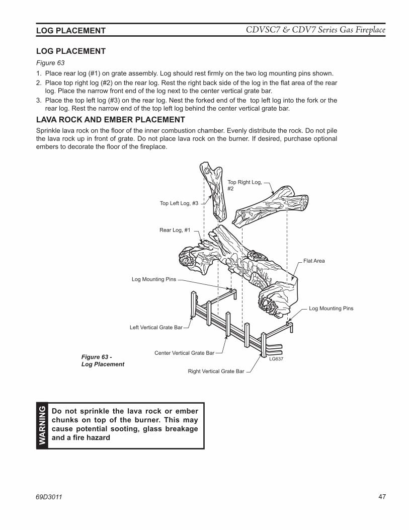
CDVSC7 & CDV7 Series Gas Fireplace
69D3011 47
LG637CDV logs
loG plaCeMenT
loG plaCeMenTFigure 631. Place rear log (#1) on grate assembly. Log should rest firmly on the two log mounting pins shown. 2. Place top right log (#2) on the rear log. Rest the right back side of the log in the flat area of the rear
log. Place the narrow front end of the log next to the center vertical grate bar.3. Place the top left log (#3) on the rear log. Nest the forked end of the top left log into the fork or the
rear log. Rest the narrow end of the top left log behind the center vertical grate bar.
laVa RoCK anD eMBeR plaCeMenTSprinkle lava rock on the floor of the inner combustion chamber. Evenly distribute the rock. Do not pile the lava rock up in front of grate. Do not place lava rock on the burner. If desired, purchase optional embers to decorate the floor of the fireplace.
Figure 63 - Log Placement
Top Left Log, #3
Top Right Log, #2
Rear Log, #1
Left Vertical Grate Bar
Right Vertical Grate Bar
Center Vertical Grate Bar
Log Mounting Pins
Flat Area
Log Mounting Pins
LG637
wa
Rn
InG Do not sprinkle the lava rock or ember
chunks on top of the burner. This may cause potential sooting, glass breakage and a fire hazard
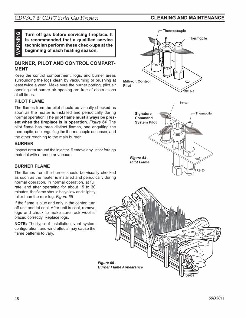
CDVSC7 & CDV7 Series Gas Fireplace
48 69D3011
BuRneR, pIloT anD ConTRol CoMpaRT-MenTKeep the control compartment, logs, and burner areas surrounding the logs clean by vacuuming or brushing at least twice a year. Make sure the burner porting, pilot air opening and burner air opening are free of obstructions at all times.pIloT FlaMeThe flames from the pilot should be visually checked as soon as the heater is installed and periodically during normal operation. The pilot flame must always be pres-ent when the fireplace is in operation. Figure 64. The pilot flame has three distinct flames, one engulfing the thermopile, one engulfing the thermocouple or sensor, and the other reaching to the main burner. BuRneRInspect area around the injector. Remove any lint or foreign material with a brush or vacuum.
BuRneR FlaMeThe flames from the burner should be visually checked as soon as the heater is installed and periodically during normal operation. In normal operation, at full rate, and after operating for about 15 to 30 minutes, the flame should be yellow and slightly taller than the rear log. Figure 65If the flame is blue and only in the center, turn off unit and let cool. After unit is cool, remove logs and check to make sure rock wool is placed correctly. Replace logs. noTe: The type of installation, vent system configuration, and wind effects may cause the flame patterns to vary.
CleanInG anD MaInTenanCe w
aR
nIn
G Turn off gas before servicing fireplace. It is recommended that a qualified service technician perform these check-ups at the beginning of each heating season.
FP1943pilot flame
Thermopile
Thermocouple
FP1943
LG638CDV7 log flame
Figure 65 - Burner Flame Appearance
LG638
Figure 64 - Pilot Flame
FP2453hooded pilot flames
Sensor
Thermopile
FP2453
Signature Command System pilot
Millivolt Control pilot
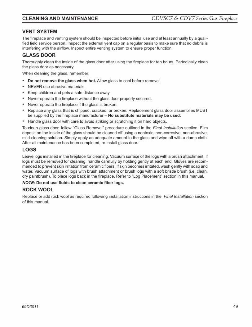
CDVSC7 & CDV7 Series Gas Fireplace
69D3011 49
CleanInG anD MaInTenanCe
VenT SySTeMThe fireplace and venting system should be inspected before initial use and at least annually by a quali-fied field service person. Inspect the external vent cap on a regular basis to make sure that no debris is interfering with the airflow. Inspect entire venting system to ensure proper function.
GlaSS DooRThoroughly clean the inside of the glass door after using the fireplace for ten hours. Periodically clean the glass door as necessary. When cleaning the glass, remember:
• Do not remove the glass when hot. Allow glass to cool before removal.• NEVER use abrasive materials.• Keep children and pets a safe distance away.• Never operate the fireplace without the glass door properly secured.• Never operate the fireplace if the glass is broken.• Replace any glass that is chipped, cracked, or broken. Replacement glass door assemblies MUST
be supplied by the fireplace manufacturer – no substitute materials may be used.• Handle glass door with care to avoid striking or scratching it on hard objects.To clean glass door, follow “Glass Removal” procedure outlined in the Final Installation section. Film deposit on the inside of the glass should be cleaned off using a nontoxic, non-corrosive, non-abrasive, mild-cleaning solution. Simply apply an adequate amount to the glass and wipe off with a damp cloth. After all maintenance has been completed, re-install glass door.
loGSLeave logs installed in the fireplace for cleaning. Vacuum surface of the logs with a brush attachment. If logs must be removed for cleaning, handle carefully by holding gently at each end. Gloves are recom-mended to prevent skin irritation from ceramic fibers. If skin becomes irritated, wash gently with soap and water. Vacuum surface of logs with brush attachment or brush logs with a soft bristle brush (i.e. clean, dry paintbrush). To place logs back in the fireplace, Refer to “Log Placement” section in this manual. NOTE: Do not use fluids to clean ceramic fiber logs.
RoCK woolReplace or add rock wool as required following installation instructions in the Final Installation section of this manual.
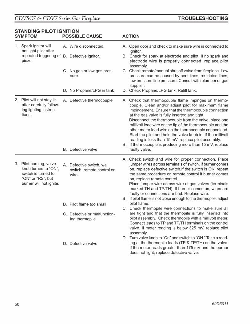
CDVSC7 & CDV7 Series Gas Fireplace
50 69D3011
STanDInG pIloT IGnITIon
TRouBleShooTInG
SyMpToM poSSIBle CauSe aCTIon
1. Spark ignitor will not light pilot after repeated triggering of piezo.
2. Pilot will not stay lit after carefully follow-ing lighting instruc-tions.
3. Pilot burning, valve knob turned to “ON”, switch is turned to “ON” or “RS”, but burner will not ignite.
A. Wire disconnected.
B. Defective ignitor.
C. No gas or low gas pres-sure.
D. No Propane/LPG in tank
A. Defective thermocouple
B. Defective valve
A. Defective switch, wall switch, remote control or wire
B. Pilot flame too small
C. Defective or malfunction-ing thermopile
D. Defective valve
A. Open door and check to make sure wire is connected to ignitor.
B. Check for spark at electrode and pilot. If no spark and electrode wire is properly connected, replace pilot assembly.
C. Check remote/manual shut off valve from fireplace. Low pressure can be caused by bent lines, restricted lines, low pressure line pressure. Consult with plumber or gas supplier.
D. Check Propane/LPG tank. Refill tank.
A. Check that thermocouple flame impinges on thermo-couple. Clean and/or adjust pilot for maximum flame impingement. Ensure that the thermocouple connection at the gas valve is fully inserted and tight.
Disconnect the thermocouple from the valve, place one millivolt lead wire on the tip of the thermocouple and the other meter lead wire on the thermocouple copper lead. Start the pilot and hold the valve knob in. If the millivolt reading is less than 15 mV, replace pilot assembly.
B. If thermocouple is producing more than 15 mV, replace faulty valve.
A. Check switch and wire for proper connection. Place jumper wires across terminals of switch. If burner comes on, replace defective switch.If the switch is OK, repeat the same procedure on remote control If burner comes on, replace remote control.
Place jumper wire across wire at gas valves (terminals marked TH and TP/TH). If burner comes on, wires are faulty or connections are bad. Replace wire.
B. If pilot flame is not close enough to the thermopile, adjust pilot flame.
C. Check thermopile wire connections to make sure all are tight and that the thermopile is fully inserted into pilot assembly. Check thermopile with a millivolt meter. Connect leads to TP and TP/TH terminals on the control valve. If meter reading is below 325 mV, replace pilot assembly.
D. Turn valve knob to “On” and switch to “ON.” Take a read-ing at the thermopile leads (TP & TP/TH) on the valve. If the meter reads greater than 175 mV and the burner does not light, replace defective valve.
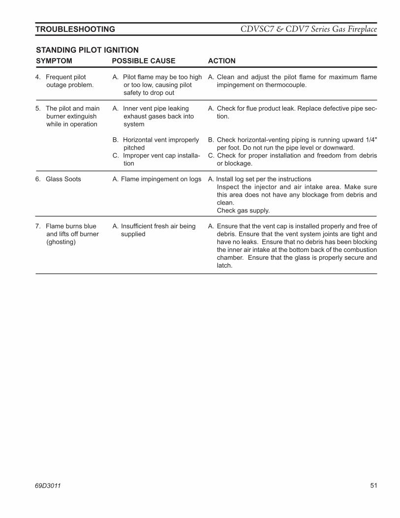
CDVSC7 & CDV7 Series Gas Fireplace
69D3011 51
STanDInG pIloT IGnITIonSyMpToM poSSIBle CauSe aCTIon
4. Frequent pilot outage problem.
5. The pilot and main burner extinguish while in operation
6. Glass Soots
7. Flame burns blue and lifts off burner (ghosting)
A. Pilot flame may be too high or too low, causing pilot safety to drop out
A. Inner vent pipe leaking exhaust gases back into system
B. Horizontal vent improperly pitched
C. Improper vent cap installa-tion
A. Flame impingement on logs
A. Insufficient fresh air being supplied
A. Clean and adjust the pilot flame for maximum flame impingement on thermocouple.
A. Check for flue product leak. Replace defective pipe sec-tion.
B. Check horizontal-venting piping is running upward 1/4" per foot. Do not run the pipe level or downward.
C. Check for proper installation and freedom from debris or blockage.
A. Install log set per the instructions Inspect the injector and air intake area. Make sure
this area does not have any blockage from debris and clean.
Check gas supply.
A. Ensure that the vent cap is installed properly and free of debris. Ensure that the vent system joints are tight and have no leaks. Ensure that no debris has been blocking the inner air intake at the bottom back of the combustion chamber. Ensure that the glass is properly secure and latch.
TRouBleShooTInG
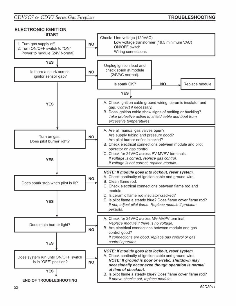
CDVSC7 & CDV7 Series Gas Fireplace
52 69D3011
eleCTRonIC IGnITIon
TRouBleShooTInG
STaRT
1. Turn gas supply off.2. Turn ON/OFF switch to “ON” Power to module (24V Normal)
yeS
Is there a spark across ignitor sensor gap?
yeS
Turn on gas. Does pilot burner light?
yeS
Does spark stop when pilot is lit?
yeS
Does main burner light?
yeS
Does system run until ON/OFF switch is in “OFF” position?
yeS
enD oF TRouBleShooTInG
Check: Line voltage (120VAC) Low voltage transformer (19.5 minimum VAC) ON/OFF switch Wiring connections
Unplug ignition lead and check spark at module (24VAC normal).
Is spark OK? no Replace module
yeS
A. Check ignition cable ground wiring, ceramic insulator and gap. Correct if necessary.
B. Does ignition cable show signs of melting or buckling? Take protective action to shield cable and boot from excessive temperatures.
A. Are all manual gas valves open? Are supply tubing and pressure good? Are pilot burner orifies blocked?B. Check electrical connections between module and pilot
operator on gas control.C. Check for 24VAC across PV-MVPV terminals. If voltage is correct, replace gas control. If voltage is not correct, replace module.
NOTE: If module goes into lockout, reset system.A. Check continuity of ignition cable and ground wire.B. Clean flame rod.C. Check electrical connections between flame rod and
module.D. Is ceramic flame rod insulator cracked?E. Is pilot flame a steady blue? Does flame cover flame rod? If not, adjust pilot flame. Replace module if problem
persists.
A. Check for 24VAC across MV-MVPV terminal. Replace module if there is no voltage. B. Are electrical connections between module and gas
control good? If connections are good, replace gas control or gas control operator.
NOTE: If module goes into lockout, reset system.A. Check continuity of ignition cable and ground wire. NOTE: If ground is poor or erratic, shutdown may
occasionally occur even though operation is normal at time of checkout.
B. Is pilot flame a steady blue? Does flame cover flame rod? If above checks out, replace module.
no
no
no
no
no
no
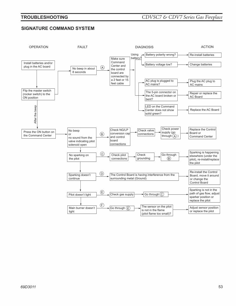
CDVSC7 & CDV7 Series Gas Fireplace
69D3011 53
TRouBleShooTInG
OPERATION
Install batteries and/or plug in the AC board
Flip the master switch (rocker switch) to theON position
Press the ON button on the Command Center
FAULT
No beep in about 8 seconds
No beep orno sound from the valve indicating pilot solenoid open
No sparking onthe pilot
Sparking doesn’tcontinue
Pilot doesn’t light
Main burner doesn’tlight
DIAGNOSIS
Make sure CommandCenter and the control board are connected by a 2 feet or 15 feet cable
Check NG/LP conversion cap and controlboardconnections
Check pilot connections
The Control Board is having interference from the surrounding metal (Ground)
Check gas supply
Go through
Battery polarity wrong?
LED on the Command Center does not show solid green?
The 5-pin connector on the AC board broken or bent?
AC plug is plugged to AC mains?
Battery voltage low?
Usingbattery?
Check valve connections
Check power supply (go through ) A
E
Checkgrounding
Go through B
Go through C
The sensor on the pilotis not in the flame(pilot flame too small)?
ACTION
Re-install batteries
Change batteries
Plug the AC plug to AC mains
Repair or replace theAC Board
Replace the AC Board
Replace the ControlBoard orCommand Center
Sparking is happening elsewhere (under the pilot), re-install/replace the pilot
Re-install the ControlBoard, move it around or change the Control Board
Sparking is not in thepath of gas flow, adjust sparker position orreplace the pilot
Adjust sensor positionor replace the pilot
Afte
r the
bee
p
A
B
C
D
E
F
FP1911 troubleshoot sc 8/08
SIGnaTuRe CoMManD SySTeM
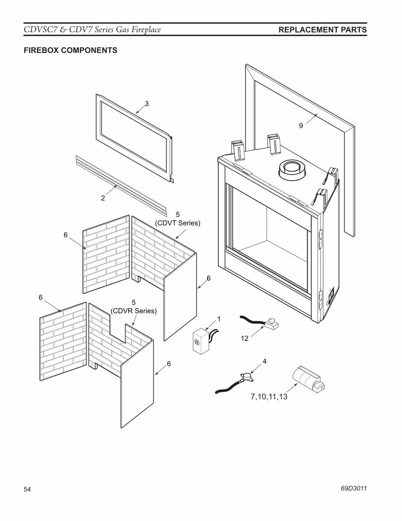
CDVSC7 & CDV7 Series Gas Fireplace
54 69D3011
ReplaCeMenT paRTS
FIReBox CoMponenTS
1
4
2
3
6
6
5(CDVR Series)
5(CDVT Series)
6
6
12
9
7,10,11,13
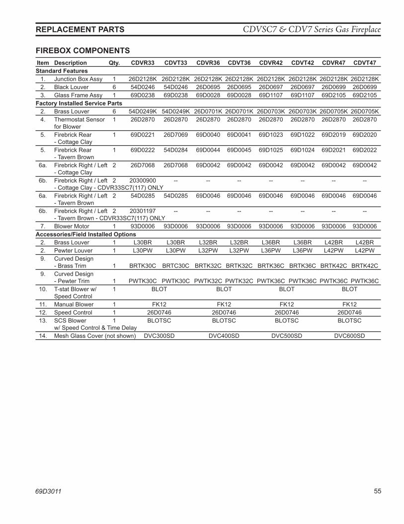
CDVSC7 & CDV7 Series Gas Fireplace
69D3011 55
FIReBox CoMponenTS
ReplaCeMenT paRTS
Item Description qty. CDVR33 CDVT33 CDVR36 CDVT36 CDVR42 CDVT42 CDVR47 CDVT47 Standard Features 1. Junction Box Assy 1 26D2128K 26D2128K 26D2128K 26D2128K 26D2128K 26D2128K 26D2128K 26D2128K 2. Black Louver 6 54D0246 54D0246 26D0695 26D0695 26D0697 26D0697 26D0699 26D0699 3. Glass Frame Assy 1 69D0238 69D0238 69D0028 69D0028 69D1107 69D1107 69D2105 69D2105 Factory Installed Service parts 2. Brass Louver 6 54D0249K 54D0249K 26D0701K 26D0701K 26D0703K 26D0703K 26D0705K 26D0705K 4. Thermostat Sensor 1 26D2870 26D2870 26D2870 26D2870 26D2870 26D2870 26D2870 26D2870 for Blower 5. Firebrick Rear 1 69D0221 26D7069 69D0040 69D0041 69D1023 69D1022 69D2019 69D2020 - Cottage Clay 5. Firebrick Rear 1 69D0222 54D0284 69D0044 69D0045 69D1025 69D1024 69D2021 69D2022 - Tavern Brown 6a. Firebrick Right / Left 2 26D7068 26D7068 69D0042 69D0042 69D0042 69D0042 69D0042 69D0042 - Cottage Clay 6b. Firebrick Right / Left 2 20300900 -- -- -- -- -- -- -- - Cottage Clay - CDVR33SC7(117) ONLY 6a. Firebrick Right / Left 2 54D0285 54D0285 69D0046 69D0046 69D0046 69D0046 69D0046 69D0046 - Tavern Brown 6b. Firebrick Right / Left 2 20301197 -- -- -- -- -- -- -- - Tavern Brown - CDVR33SC7(117) ONLY 7. Blower Motor 1 93D0006 93D0006 93D0006 93D0006 93D0006 93D0006 93D0006 93D0006 accessories/Field Installed options 2. Brass Louver 1 L30BR L30BR L32BR L32BR L36BR L36BR L42BR L42BR 2. Pewter Louver 1 L30PW L30PW L32PW L32PW L36PW L36PW L42PW L42PW 9. Curved Design - Brass Trim 1 BRTK30C BRTC30C BRTK32C BRTK32C BRTK36C BRTK36C BRTK42C BRTK42C 9. Curved Design - Pewter Trim 1 PWTK30C PWTK30C PWTK32C PWTK32C PWTK36C PWTK36C PWTK36C PWTK36C 10. T-stat Blower w/ 1 BLOT BLOT BLOT BLOT Speed Control 11. Manual Blower 1 FK12 FK12 FK12 FK12 12. Speed Control 1 26D0746 26D0746 26D0746 26D0746 13. SCS Blower 1 BLOTSC BLOTSC BLOTSC BLOTSC w/ Speed Control & Time Delay 14. Mesh Glass Cover (not shown) DVC300SD DVC400SD DVC500SD DVC600SD
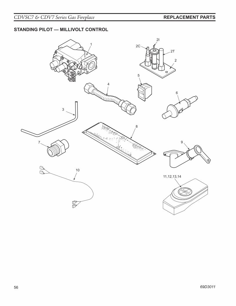
CDVSC7 & CDV7 Series Gas Fireplace
56 69D3011
ReplaCeMenT paRTS
STanDInG pIloT — MIllIVolT ConTRol
1 2C
2I
2T
2
4
5
6
3
8
97
10
11,12,13,14
693011CDV millivolt parts
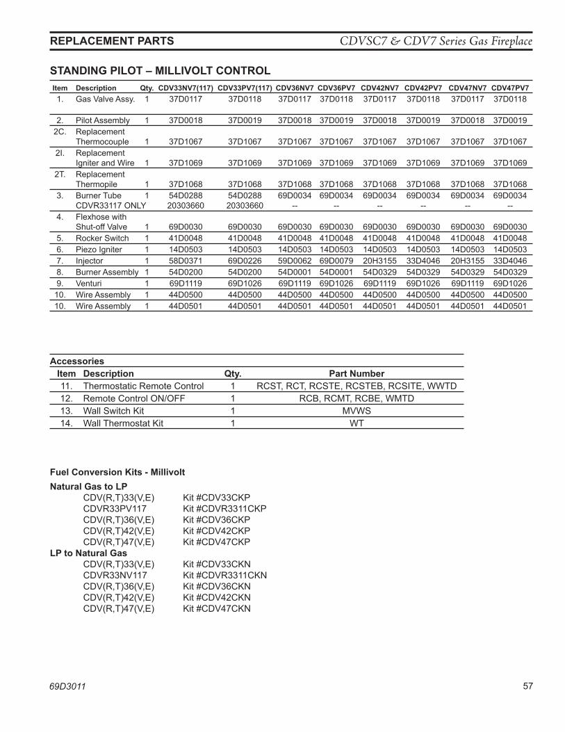
CDVSC7 & CDV7 Series Gas Fireplace
69D3011 57
STanDInG pIloT – MIllIVolT ConTRol
ReplaCeMenT paRTS
Item Description qty. CDV33nV7(117) CDV33pV7(117) CDV36nV7 CDV36pV7 CDV42nV7 CDV42pV7 CDV47nV7 CDV47pV7 1. Gas Valve Assy. 1 37D0117 37D0118 37D0117 37D0118 37D0117 37D0118 37D0117 37D0118
2. Pilot Assembly 1 37D0018 37D0019 37D0018 37D0019 37D0018 37D0019 37D0018 37D0019 2C. Replacement Thermocouple 1 37D1067 37D1067 37D1067 37D1067 37D1067 37D1067 37D1067 37D1067 2I. Replacement Igniter and Wire 1 37D1069 37D1069 37D1069 37D1069 37D1069 37D1069 37D1069 37D1069 2T. Replacement Thermopile 1 37D1068 37D1068 37D1068 37D1068 37D1068 37D1068 37D1068 37D1068 3. Burner Tube 1 54D0288 54D0288 69D0034 69D0034 69D0034 69D0034 69D0034 69D0034 CDVR33117 ONLY 20303660 20303660 -- -- -- -- -- -- 4. Flexhose with Shut-off Valve 1 69D0030 69D0030 69D0030 69D0030 69D0030 69D0030 69D0030 69D0030 5. Rocker Switch 1 41D0048 41D0048 41D0048 41D0048 41D0048 41D0048 41D0048 41D0048 6. Piezo Igniter 1 14D0503 14D0503 14D0503 14D0503 14D0503 14D0503 14D0503 14D0503 7. Injector 1 58D0371 69D0226 59D0062 69D0079 20H3155 33D4046 20H3155 33D4046 8. Burner Assembly 1 54D0200 54D0200 54D0001 54D0001 54D0329 54D0329 54D0329 54D0329 9. Venturi 1 69D1119 69D1026 69D1119 69D1026 69D1119 69D1026 69D1119 69D1026 10. Wire Assembly 1 44D0500 44D0500 44D0500 44D0500 44D0500 44D0500 44D0500 44D0500 10. Wire Assembly 1 44D0501 44D0501 44D0501 44D0501 44D0501 44D0501 44D0501 44D0501
accessories Item Description qty. part number 11. Thermostatic Remote Control 1 RCST, RCT, RCSTE, RCSTEB, RCSITE, WWTD 12. Remote Control ON/OFF 1 RCB, RCMT, RCBE, WMTD 13. Wall Switch Kit 1 MVWS 14. Wall Thermostat Kit 1 WT
Fuel Conversion Kits - Millivoltnatural Gas to lp CDV(R,T)33(V,E) Kit #CDV33CKP CDVR33PV117 Kit #CDVR3311CKP CDV(R,T)36(V,E) Kit #CDV36CKP CDV(R,T)42(V,E) Kit #CDV42CKP CDV(R,T)47(V,E) Kit #CDV47CKPlp to natural Gas CDV(R,T)33(V,E) Kit #CDV33CKN CDVR33NV117 Kit #CDVR3311CKN CDV(R,T)36(V,E) Kit #CDV36CKN CDV(R,T)42(V,E) Kit #CDV42CKN CDV(R,T)47(V,E) Kit #CDV47CKN
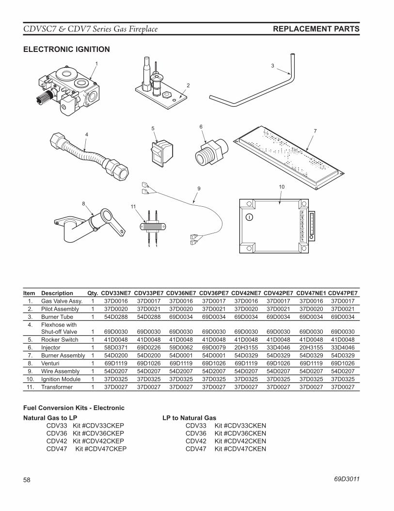
CDVSC7 & CDV7 Series Gas Fireplace
58 69D3011
eleCTRonIC IGnITIon
ReplaCeMenT paRTS
Item Description qty. CDV33ne7 CDV33pe7 CDV36ne7 CDV36pe7 CDV42ne7 CDV42pe7 CDV47ne1 CDV47pe7 1. Gas Valve Assy. 1 37D0016 37D0017 37D0016 37D0017 37D0016 37D0017 37D0016 37D0017 2. Pilot Assembly 1 37D0020 37D0021 37D0020 37D0021 37D0020 37D0021 37D0020 37D0021 3. Burner Tube 1 54D0288 54D0288 69D0034 69D0034 69D0034 69D0034 69D0034 69D0034 4. Flexhose with Shut-off Valve 1 69D0030 69D0030 69D0030 69D0030 69D0030 69D0030 69D0030 69D0030 5. Rocker Switch 1 41D0048 41D0048 41D0048 41D0048 41D0048 41D0048 41D0048 41D0048 6. Injector 1 58D0371 69D0226 59D0062 69D0079 20H3155 33D4046 20H3155 33D4046 7. Burner Assembly 1 54D0200 54D0200 54D0001 54D0001 54D0329 54D0329 54D0329 54D0329 8. Venturi 1 69D1119 69D1026 69D1119 69D1026 69D1119 69D1026 69D1119 69D1026 9. Wire Assembly 1 54D0207 54D0207 54D2007 54D2007 54D0207 54D0207 54D0207 54D0207 10. Ignition Module 1 37D0325 37D0325 37D0325 37D0325 37D0325 37D0325 37D0325 37D0325 11. Transformer 1 37D0027 37D0027 37D0027 37D0027 37D0027 37D0027 37D0027 37D0027
45 6
3
8
9 10
11
7
1
LO
HI
2
693011CDV elect parts
#1#2
#3#4
#5#6
7#
Fuel Conversion Kits - electronicnatural Gas to lp lp to natural Gas CDV33 Kit #CDV33CKEP CDV33 Kit #CDV33CKEN CDV36 Kit #CDV36CKEP CDV36 Kit #CDV36CKEN CDV42 Kit #CDV42CKEP CDV42 Kit #CDV42CKEN CDV47 Kit #CDV47CKEP CDV47 Kit #CDV47CKEN
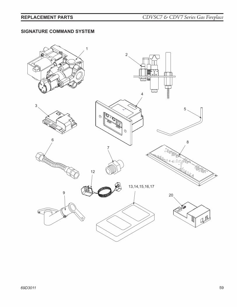
CDVSC7 & CDV7 Series Gas Fireplace
69D3011 59
ReplaCeMenT paRTS
1
2
3
4
20
5
6
7
8
9
13,14,15,16,17
693011cdvrt7 SC parts
12
SIGnaTuRe CoMManD SySTeM
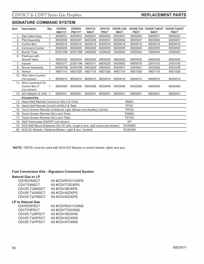
CDVSC7 & CDV7 Series Gas Fireplace
60 69D3011
ReplaCeMenT paRTS
SIGnaTuRe CoMManD SySTeMItem Description qty. CDVR33 CDVR33 CDVT33 CDVT33 CDV(R,T)36 CDV(R,T)36 CDV(R,T)42/47 CDV(R,T)42/47 nSC117 pSC117 nSC7 pSC7 nSC7 pSC7 nSC7 pSC7 1. Gas Valve Assy. 1 80D0001 80D0002 80D0001 80D0002 80D0001 80D0002 80D0001 80D0002 2. Pilot Assembly 1 80D0006 80D0007 80D0006 80D0007 80D0006 80D0007 80D0006 80D0007 3. Control Box 1 80D0018 80D0019 80D0018 80D0019 80D0018 80D0019 80D0018 80D0019 4. Command Center 1 80D0005 80D0005 80D0005 80D0005 80D0005 80D0005 80D0005 80D0005 5. Burner Tube 1 20301096 20301096 54D6029 54D6029 54D6004 54D6004 54D6004 54D6004 6. Flexhose with Shutoff Valve 1 69D0030 69D0030 69D0030 69D0030 69D0030 69D0030 69D0030 69D0030 7. Injector 1 58D0371 20301196 58D0371 69D0226 54D0062 69D0079 20H3155 20H3156 8. Burner Assembly 1 20300786 20300786 54D0200 54D0200 54D0001 54D0001 54D0329 54D0329 9. Venturi 1 69D1119 69D1026 69D1119 69D1026 69D1119 69D1026 69D1119 69D1026 10. Wire Valve Control (not shown) 1 80D0010 80D0010 80D0010 80D0010 80D0010 80D0010 80D0010 80D0010 11. Wire Command Ctr Control Box 2' 1 80D0008 80D0008 80D0008 80D0008 80D0008 80D0008 80D0008 80D0008 (not shown) 12. A/C Adapter (6 Volt) 1 80D0041 80D0041 80D0041 80D0041 80D0041 80D0041 80D0041 80D0041 accessories 13. Hand Held Remote Control w/ HI/LO & Timer RMSC 14. Hand Held Remote Control w/HI/LO & Tstat RTSC 15. Touch Screen Remote w/Optional Light, Blower and Auxiliary Control TSFSC 16. Touch Screen Remote Hi/Lo and Timer TSMSC 17. Touch Screen Remote Hi/Lo and TStat TSTSC 18. Wall Thermostat ON/OFF (not shown) WT 19. SCS Wall Mount Extension Kit (15' wire, rough-in box, wall cover) (not shown) SCSWEK 20. SCS AC Module (*Optional Blower, Light & Aux. Control) SCSACM
Fuel Conversion Kits - Signature Command Systemnatural Gas to lp CDVR33NSC7 Kit #CDVR3311CKPS CDVT33NSC7 Kit #CDVT33CKPS CDV(R,T)36NSC7 Kit #CDV36CKPS CDV(R,T)42NSC7 Kit #CDV42CKPS CDV(R,T)47NSC7 Kit #CDV42CKPSlp to natural Gas CDVR33PSC7 Kit #CDVR3311CKNS CDVT33PSC7 Kit #CDVT33CKNS CDV(R,T)36PSC7 Kit #CDV36CKNS CDV(R,T)42PSC7 Kit #CDV42CKNS CDV(R,T)47PSC7 Kit #CDV47CKNS
*noTe: TSFSC must be used with SCS A/C Module to control blower, lights and aux.
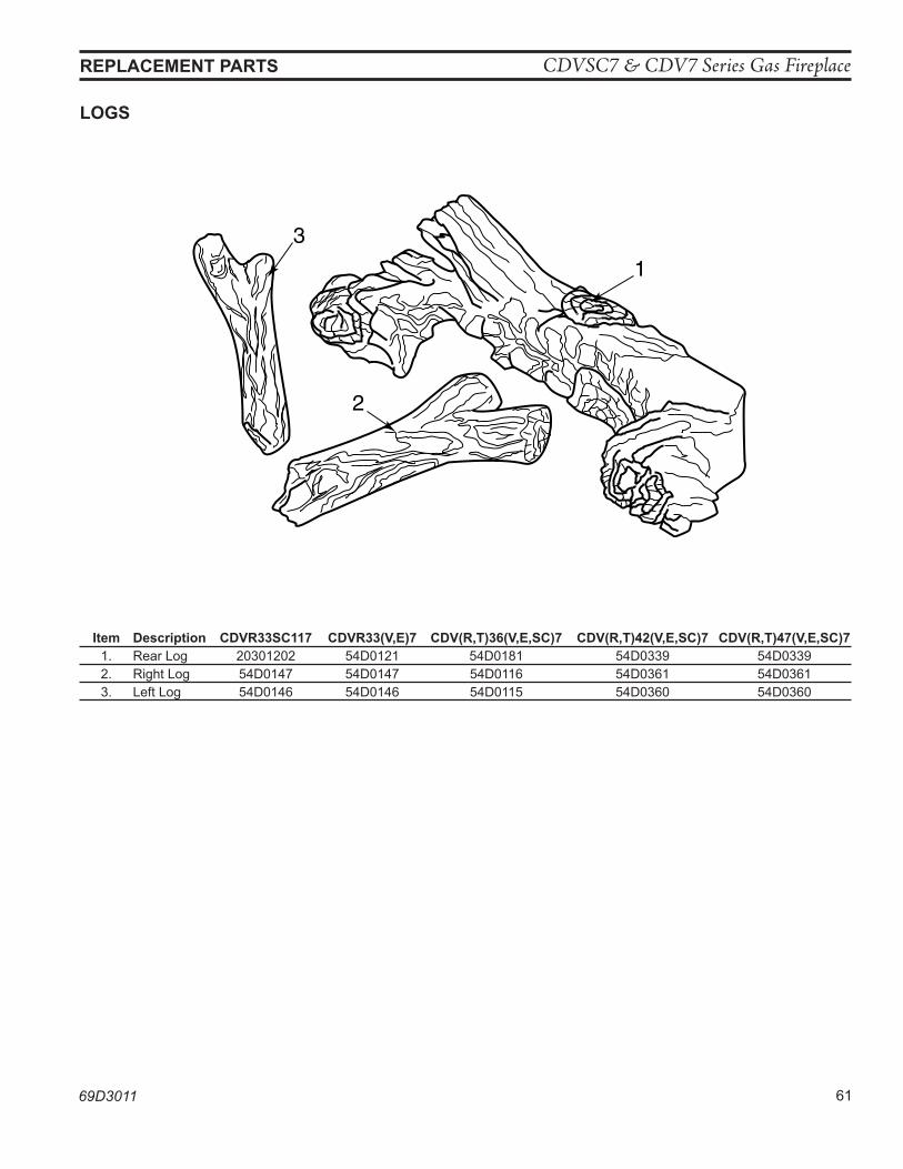
CDVSC7 & CDV7 Series Gas Fireplace
69D3011 61
1
3
2
693011cdv log parts
loGS
ReplaCeMenT paRTS
Item Description CDVR33SC117 CDVR33(V,e)7 CDV(R,T)36(V,e,SC)7 CDV(R,T)42(V,e,SC)7 CDV(R,T)47(V,e,SC)7 1. Rear Log 20301202 54D0121 54D0181 54D0339 54D0339 2. Right Log 54D0147 54D0147 54D0116 54D0361 54D0361 3. Left Log 54D0146 54D0146 54D0115 54D0360 54D0360
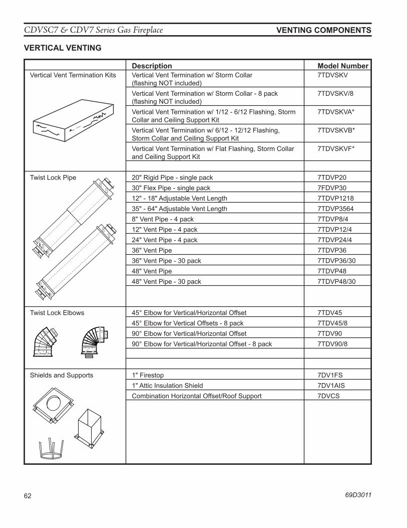
CDVSC7 & CDV7 Series Gas Fireplace
62 69D3011
VenTInG CoMponenTS
Description Model number Vertical Vent Termination Kits Vertical Vent Termination w/ Storm Collar 7TDVSKV (flashing NOT included) Vertical Vent Termination w/ Storm Collar - 8 pack 7TDVSKV/8 (flashing NOT included) Vertical Vent Termination w/ 1/12 - 6/12 Flashing, Storm 7TDVSKVA* Collar and Ceiling Support Kit Vertical Vent Termination w/ 6/12 - 12/12 Flashing, 7TDVSKVB* Storm Collar and Ceiling Support Kit Vertical Vent Termination w/ Flat Flashing, Storm Collar 7TDVSKVF* and Ceiling Support Kit
Twist Lock Pipe 20" Rigid Pipe - single pack 7TDVP20 30" Flex Pipe - single pack 7FDVP30 12" - 18" Adjustable Vent Length 7TDVP1218 35" - 64" Adjustable Vent Length 7TDVP3564 8" Vent Pipe - 4 pack 7TDVP8/4 12" Vent Pipe - 4 pack 7TDVP12/4 24" Vent Pipe - 4 pack 7TDVP24/4 36" Vent Pipe 7TDVP36 36" Vent Pipe - 30 pack 7TDVP36/30 48" Vent Pipe 7TDVP48 48" Vent Pipe - 30 pack 7TDVP48/30
Twist Lock Elbows 45° Elbow for Vertical/Horizontal Offset 7TDV45 45° Elbow for Vertical Offsets - 8 pack 7TDV45/8 90° Elbow for Vertical/Horizontal Offset 7TDV90 90° Elbow for Vertical/Horizontal Offset - 8 pack 7TDV90/8
Shields and Supports 1" Firestop 7DV1FS 1" Attic Insulation Shield 7DV1AIS Combination Horizontal Offset/Roof Support 7DVCS
584B �Vent components �Starter Kit �2/25/99 djt
584E
Ventin
g Com
pone
nts
Teles
cope
vent
2/25/9
9 dj
t
10/20
/99 tw
ist loc
k
584F
Venting
Compo
nents
Pipe se
ctions
2/25/9
9 djt
10/20
/99 tw
ist loc
k
584D �Vent Components �90 degree elbow �2/25/99 djt �10/20/99 twist lock
584C �Vent components�45 degree elbow �2/25/99 djt �10/20/99 twistlock584G �
Venting Components �Firestop spacer �2/25/99 djt
584H �Venting components �attic insulation shield �2/25/99 djt
584I �vent components �offset support �2/25/99 djt
VeRTICal VenTInG
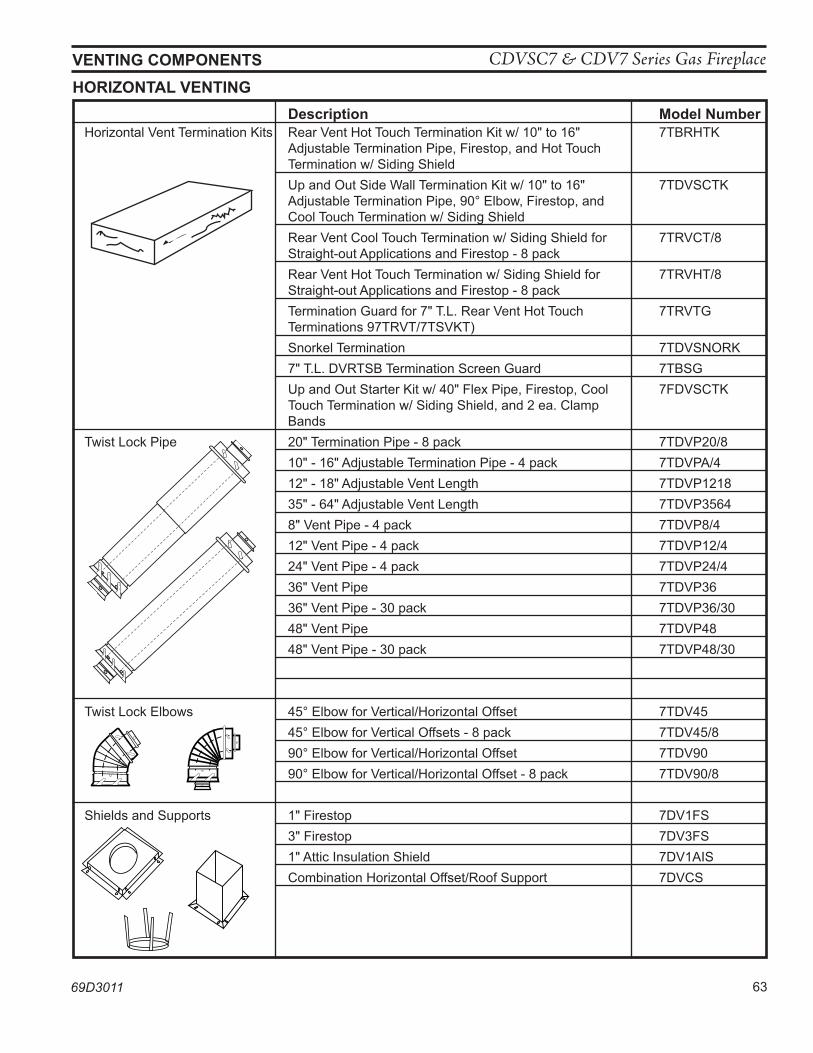
CDVSC7 & CDV7 Series Gas Fireplace
69D3011 63
VenTInG CoMponenTS
Description Model number Horizontal Vent Termination Kits Rear Vent Hot Touch Termination Kit w/ 10" to 16" 7TBRHTK Adjustable Termination Pipe, Firestop, and Hot Touch Termination w/ Siding Shield Up and Out Side Wall Termination Kit w/ 10" to 16" 7TDVSCTK Adjustable Termination Pipe, 90° Elbow, Firestop, and Cool Touch Termination w/ Siding Shield Rear Vent Cool Touch Termination w/ Siding Shield for 7TRVCT/8 Straight-out Applications and Firestop - 8 pack Rear Vent Hot Touch Termination w/ Siding Shield for 7TRVHT/8 Straight-out Applications and Firestop - 8 pack Termination Guard for 7" T.L. Rear Vent Hot Touch 7TRVTG Terminations 97TRVT/7TSVKT) Snorkel Termination 7TDVSNORK 7" T.L. DVRTSB Termination Screen Guard 7TBSG Up and Out Starter Kit w/ 40" Flex Pipe, Firestop, Cool 7FDVSCTK Touch Termination w/ Siding Shield, and 2 ea. Clamp Bands Twist Lock Pipe 20" Termination Pipe - 8 pack 7TDVP20/8 10" - 16" Adjustable Termination Pipe - 4 pack 7TDVPA/4 12" - 18" Adjustable Vent Length 7TDVP1218 35" - 64" Adjustable Vent Length 7TDVP3564 8" Vent Pipe - 4 pack 7TDVP8/4 12" Vent Pipe - 4 pack 7TDVP12/4 24" Vent Pipe - 4 pack 7TDVP24/4 36" Vent Pipe 7TDVP36 36" Vent Pipe - 30 pack 7TDVP36/30 48" Vent Pipe 7TDVP48 48" Vent Pipe - 30 pack 7TDVP48/30
Twist Lock Elbows 45° Elbow for Vertical/Horizontal Offset 7TDV45 45° Elbow for Vertical Offsets - 8 pack 7TDV45/8 90° Elbow for Vertical/Horizontal Offset 7TDV90 90° Elbow for Vertical/Horizontal Offset - 8 pack 7TDV90/8
Shields and Supports 1" Firestop 7DV1FS 3" Firestop 7DV3FS 1" Attic Insulation Shield 7DV1AIS Combination Horizontal Offset/Roof Support 7DVCS
584B �Vent components �Starter Kit �2/25/99 djt
584E
Ventin
g Com
pone
nts
Teles
cope
vent
2/25/9
9 dj
t
10/20
/99 tw
ist loc
k
584F
Venting
Compo
nents
Pipe se
ctions
2/25/9
9 djt
10/20
/99 tw
ist loc
k
584D �Vent Components �90 degree elbow �2/25/99 djt �10/20/99 twist lock
584C �Vent components�45 degree elbow �2/25/99 djt �10/20/99 twistlock584G �Venting Components �Firestop spacer �2/25/99 djt
584H �Venting components �attic insulation shield �2/25/99 djt
584I �vent components �offset support �2/25/99 djt
hoRIZonTal VenTInG
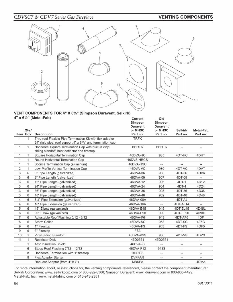
CDVSC7 & CDV7 Series Gas Fireplace
64 69D3011
VenTInG CoMponenTS
HOT
1
2
3
4
5
6
9
7
8
11
10
0004MLDV vent parts
Current old Simpson Simpson Duravent Duravent qty./ or MhSC or MhSC Selkirk Metal-Fab Item Box Description part no. part no. part no. part no. 1 1 Thru-roof Flexible Pipe Termination Kit with flex adapter TRFK -- -- -- 24" rigid pipe, roof support 4" x 65/8" and termination cap 1 1 Horizontal Square Termination Cap with built-in vinyl BHRTK BHRTK -- -- siding standoff, heat deflector and firestop 1 1 Square Horizontal Termination Cap 46DVA-HC 985 4DT-HC 4DHT 1 1 Round Horizontal Termination Cap 46DVS-HRCS -- -- -- 1 1 Sconce Termination Cap (aluminum) 46DVA-HSC -- -- -- 2 1 Low-Profile Vertical Termination Cap 46DVA-VC 980 4DT-VC 4DVT 3 6 6" Pipe Length (galvanized) 46DVA-06 908 4DT-06 4DV6 3 6 9" Pipe Length (galvanized) 46DVA-09 907 4DT-09 -- 3 6 12" Pipe Length (galvanized) 46DVA-12 906 4DT-1 4D12 3 6 24" Pipe Length (galvanized) 46DVA-24 904 4DT-4 4D24 3 6 36" Pipe Length (galvanized) 46DVA-36 903 4DT-36 4D36 3 6 48" Pipe Length (galvanized) 46DVA-48 902 4DT-48 4D48 4 6 8Z\x" Pipe Extension (galvanized) 46DVA-08A -- 4DT-AJ -- 4 6 16" Pipe Extension (galvanized) 46DVA-16A -- 4DT-AJ14 -- 5 6 45° Elbow (galvanized) 46DVA-E45 945 4DT-EL45 4D45L 6 6 90° Elbow (galvanized) 46DVA-E90 990 4DT-EL90 4D90L 7 6 Adjustable Roof Flashing 0/12 - 6/12 46DVA-F6 943 4DT-AF6 4DF 8 6 Storm Collar 46DVA-SC 953 4DT-SC 4F5C 9 6 1" Firestop 46DVA-FS 963 4DT-FS 4DF5 9 6 3" Firestop FS3 -- -- -- 10 1 Vinyl Siding Standoff 46DVA-VSS 950 4DT-VS 4DVS 11 1 Restrictor Disk 45D0551 45D0551 -- -- 1 Attic Insulation Shield 46DVA-IS -- -- -- 6 Steep Roof Flashing 7/12 - 12/12 46DVA-F12 943S -- -- 8 Horizontal Termination with 1" firestop BHRT/8 -- -- -- 8 Flex Adapter Starter DVFFA/8 -- -- -- Reducer Adapter (from 4" x 7") MBSPA -- -- 4DMA
VenT CoMponenTS FoR 4" x 6B\," (Simpson Duravent, Selkirk) 4" x 6Z\x" (Metal-Fab)
For more information about, or instructions for, the venting components referenced, please contact the component manufacturer:Selkirk Corporation: www. selkirkcorp.com or 800-992-8368; Simpson Duravent: www. duravent.com or 800-835-4429;Metal-Fab, Inc.: www.metal-fabinc.com or 316-943-2351

CDVSC7 & CDV7 Series Gas Fireplace
69D3011 65
CDVSC7 & CDV7 Series Gas Fireplace
66 69D3011
noTe ReGaRDInG VenTeD pRoDuCTSThis product must be installed by a licensed plumber or gas fitter when installed within the Commonwealth of Massachusetts.Any residence with a direct vent product must have a CO detector installed in the residence.Installation of the fireplace or vented gas log in the State of Massachusetts requires the damper to be permanently removed or welded in the fully open position.In addition, a naturally vented gas log may not be installed in a bedroom or bathroom in the State of Massachusetts.Flex line installation must not exceed 36 inches and must have a T shutoff valve.
noTe ReGaRDInG VenT FRee pRoDuCTSThis product must be installed by a licensed plumber or gas fitter when installed within the Commonwealth of Massachusetts.In addition, vent free products may not be installed in a bedroom or bathroom regardless of size or type in the State of Massachusetts.Flex line installation must not exceed 36 inches and must have a T shutoff valve.
CaRBon MonoxIDe DeTeCToR RequIReMenTS(2) Revise 10.8.3 by adding the following additional requirements:(a) For all side wall horizontally vented gas fueled equipment installed in every dwelling, building or structure used in whole or in part for residential purposes, including those owned or operated by the Commonwealth and where the side wall exhaust vent termination is less than seven (7) feet above finished grade in the area of the venting, including but not limited to decks and porches, the following requirements shall be satisfied:1. Installation of carbon monoxide detectors. At the time of installation of the side wall horizontal vented gas fueled equipment, the installing plumber or gas fitter shall observe that a hard wired carbon monoxide detector with an alarm and battery back-up is installed on the floor level where the gas equipment is to be installed. In addition, the installing plumber or gas fitter shall observe that a battery operated or hard wired carbon monoxide detector with an alarm is installed on each additional level of the dwelling, building or structure served by the side wall horizontal vented gas fueled equipment. It shall be the responsibility of the property owner to secure the services of qualified licensed professionals for the installation of hard wired carbon monoxide detectors a. In the event that the side wall horizontally vented gas fueled equipment is installed in a crawl space or an attic, the hard wired carbon monoxide detector with alarm and battery back-up may be installed on the next adjacent floor level. b. In the event that the requirements of this subdivision can not be met at the time of completion of installation, the owner shall have a period of thirty (30) days to comply with the above requirements; provided, however, that during said thirty (30) day period, a battery operated carbon monoxide detector with an alarm shall be installed.
Massachusetts Residents only — please read and follow these special requirements
2. approved Carbon Monoxide Detectors. Each carbon monoxide detector as required in accordance with the above provisions shall comply with NFPA 720 and be ANSI/UL 2034 listed and IAS certified.3. Signage. A metal or plastic identification plate shall be permanently mounted to the exterior of the building at a minimum height of eight (8) feet above grade directly in line with the exhaust vent terminal for the horizontally vented gas fueled heating appliance or equipment. The sign shall read, in print size no less than one-half (1/2) inch in size, “GAS VENT DIRECTLY BELOW. KEEP CLEAR OF ALL OBSTRUCTIONS.”4. Inspection. The state or local gas inspector of the side wall horizontally vented gas fueled equipment shall not approve the installation unless, upon inspection, the inspector observes carbon monoxide detectors and signage installed in accordance with the provisions of 248 CMR 5.08(2)(a)1 through 4.(b) exemptions: The following equipment is exempt from 248 CMR 5.08(2)(a)1 through 4:1. The equipment listed in Chapter 10 entitled "Equipment Not Required To Be Vented" in the most current edition of NFPA 54 as adopted by the Board; and2. Product Approved side wall horizontally vented gas fueled equipment installed in a room or structure separate from the dwelling, building or structure used in whole or in part for residential purposes.(c) Manufacturer requirements — Gas equipment Venting System provided. When the manufacturer of Product Approved side wall horizontally vented gas equipment provides a venting system design or venting system components with the equipment, the instructions provided by the manufacturer for installation of the equipment and the venting system shall include:1. Detailed instructions for the installation of the venting system design or the venting system components; and2. A complete parts list for the venting system design or venting system.(d) Manufacturer requirements — Gas equipment Venting System not provided. When the manufacturer of a Product Approved side wall horizontally vented gas fueled equipment does not provide the parts for venting the flue gases, but identifies “special venting systems,” the following requirements shall be satisfied by the manufacturer:1. The referenced "special venting system" instructions shall be included with the appliance or equipment installation instructions; and2. The “special venting systems” shall be Product Approved by the Board, and the instructions for that system shall include a parts list and detailed installation instructions.(e) A copy of all installation instructions for all Product Approved side wall horizontally vented gas fueled equipment, all venting instructions, all parts lists for venting instructions, and/or all venting design
CDVSC7 & CDV7 Series Gas Fireplace
69D3011 67
lIMITeD lIFeTIMe waRRanTy polICylIFeTIMe waRRanTyThe following components are warranted for life to the original owner, subject to proof of purchase: Firebox, Combustion Chamber, Heat Exchanger, Grate and Stainless Steel Burners.FIVe yeaR waRRanTyThe following components are warranted five (5) years to the original owner, subject of proof of purchase: Ceramic Fiber Logs.BaSIC waRRanTyMHSC warrants the components and materials in your gas appliance to be free from manufacturing and material defects for a period of two years from date of installation. After installation, if any of the components manufactured by MHSC in the appliance are found to be defective in materials or workmanship, MHSC will, at its option, replace or repair the defective components at no charge to the original owner. MHSC will also pay for reasonable labor costs incurred in replacing or repairing such components for a period of two years from date of installation. Any products presented for warranty repair must be accompanied by a dated proof of purchase.This Limited Lifetime Warranty will be void if the appliance in not installed by a qualified installer in accordance with the installation instructions. The Limited Lifetime Warranty will also be void if the appliance is not operated and maintained according to the operating instructions supplied with the appliance, and does not extend to (1) firebox/burner assembly damage by accident, neglect, misuse, abuse, alterations, negligence of others, including the installation thereof by unqualified installers, (2) the costs of removal, reinstallation or transportation of defective parts on the appliance, or (3) incidental or consequential damage. All service work must be performed by an authorized service representative.This warranty is expressly in lieu of other warranties, express or implied, including the warranty of merchantability of fitness for purpose and of all other obligations or liabilities. MHSC does not assume for it any other obligations or liabilities in connection with sale or use of the appliance. It states that do not allow limitations on how long an implied warranty lasts, or do not allow exclu-sion of indirect damage, those limitations of exclusions may not apply to you. You may also have additional rights not covered in the Limited Lifetime Warranty.MHSC reserves the right to investigate any and all the claims against the Limited Lifetime Warranty and decide upon method of settlement.IF waRRanTy SeRVICe IS neeDeD...
1. Contact your supplier. Make sure you have your warranty, your sales receipt and the model/serial number of your MHSC product.
2. DO NOT ATTEMPT TO DO ANY SERVICE WORK YOURSELF.
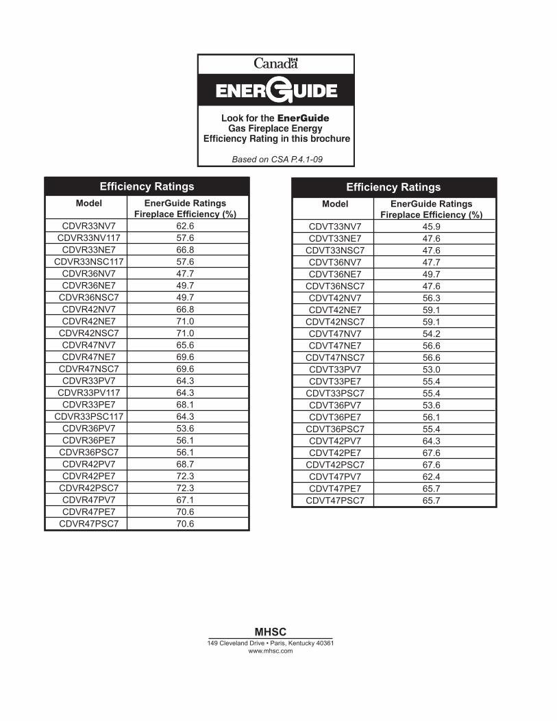
MhSC149 Cleveland Drive • Paris, Kentucky 40361
www.mhsc.com
Based on CSA P.4.1-09
Based on CSA P.4.1-09
Recherchez dans la brochureles caractéristique de rendement
énergétique de foyer au gazÉnerguide
Selon CSA P.4.1-09
efficiency Ratings Model enerGuide Ratings Fireplace efficiency (%) CDVR33NV7 62.6 CDVR33NV117 57.6 CDVR33NE7 66.8 CDVR33NSC117 57.6 CDVR36NV7 47.7 CDVR36NE7 49.7 CDVR36NSC7 49.7 CDVR42NV7 66.8 CDVR42NE7 71.0 CDVR42NSC7 71.0 CDVR47NV7 65.6 CDVR47NE7 69.6 CDVR47NSC7 69.6 CDVR33PV7 64.3 CDVR33PV117 64.3 CDVR33PE7 68.1 CDVR33PSC117 64.3 CDVR36PV7 53.6 CDVR36PE7 56.1 CDVR36PSC7 56.1 CDVR42PV7 68.7 CDVR42PE7 72.3 CDVR42PSC7 72.3 CDVR47PV7 67.1 CDVR47PE7 70.6 CDVR47PSC7 70.6
efficiency Ratings Model enerGuide Ratings Fireplace efficiency (%) CDVT33NV7 45.9 CDVT33NE7 47.6 CDVT33NSC7 47.6 CDVT36NV7 47.7 CDVT36NE7 49.7 CDVT36NSC7 47.6 CDVT42NV7 56.3 CDVT42NE7 59.1 CDVT42NSC7 59.1 CDVT47NV7 54.2 CDVT47NE7 56.6 CDVT47NSC7 56.6 CDVT33PV7 53.0 CDVT33PE7 55.4 CDVT33PSC7 55.4 CDVT36PV7 53.6 CDVT36PE7 56.1 CDVT36PSC7 55.4 CDVT42PV7 64.3 CDVT42PE7 67.6 CDVT42PSC7 67.6 CDVT47PV7 62.4 CDVT47PE7 65.7 CDVT47PSC7 65.7