Embed Size (px)
Citation preview

6–80 Advanced Usage and General Modeling Tips TRACE 700 User’s Manual • CDS-PRM001-ENModeling for LEED®
Modeling for LEED®
USGBC’s Leadership in Energy and Environmental Design (LEED) program updates its products to closely align with the latest industry standards. LEED version 3, the most recent version of LEED (also known as LEED 2009) incorporates the latest standards such as ASHRAE 90.1-2007 and ASHRAE 62.1-2007.
TRACE 700 has been updated to reflect the latest changes in ASHRAE standards and can be used to achieve LEED credits under version 3. Specifically, TRACE 700 can model a building’s energy use to determine its efficiency for LEED Energy and Atmosphere credit 1 (EAc1), option 1. How to model the proposed building and baseline building in order to compare energy efficiency is outlined below.
Refer to “Additional LEED credits” on page 6–90 for a list of credits TRACE 700 may help to achieve.
Note: If LEED version 2.2 is used, the following guidelines still apply. However, version 2.2 references ASHRAE Standard 90.1-2004, not 2007. TRACE is compatible with both versions of the standard. Ultimately, it is the user’s responsibility to ensure compliance with the appropriate standard’s requirements. Contact C.D.S. support with any compatibility questions not covered in this guide.
Before you begin the TRACE analysis, we recommend that you review the following:
■ LEED Reference Guide for Green Building Design and Construction version 3, specifically Energy and Atmosphere Prerequisite 2 (EAp2) requirements and Energy and Atmosphere Credit 1 (EAc1) requirements
■ ASHRAE Standard 90.1-2007, specifically sections 5.4, 6.4, 7.4, 8.4, 9.4, 10.4, and Table G3.1
■ ASHRAE Standard 90.1-2007 User’s Manual
CDS-PRM001-EN_new.book Page 80 Friday, September 3, 2010 1:17 PM

6–81CDS-PRM001-EN • TRACE 700 User’s Manual Advanced Usage and General Modeling TipsModeling for LEED®
Proposed buildingStart a LEED model with the proposed design. As a general rule, the building should be modeled per its design specifications.
When complete, the proposed building must:
■ Comply with the mandatory requirements of ASHRAE 90.1-2007
■ Meet the requirements of LEED EAp2 and EAc1
■ Match the design parameters
The following is a recommended workflow for building the proposed building in TRACE. Many methods exist, yet differ depending on company policies and practices. Please treat this as one possible path to follow.
Collect dataTo save time, collect and organize the data for the proposed building prior to beginning the analysis. While the following is not an extensive list, information you will need includes:
■ Envelope construction information (e.g. wall constructions, roof constructions, window types)
■ Occupancy capacities and schedules per space type
■ Interior lighting power densities and fixture types per space type
■ Exterior lighting power densities
■ Receptacle (miscellaneous) load design per space type
■ Thermal (HVAC) zoning (determine space types with common thermal properties)
■ HVAC system design (e.g. system types and configuration, temperature setpoints/driftpoints, control methods)
■ Equipment design (e.g. manufacturer selections, sequencing, efficiency)
■ Local utility rate structure
■ Energy Conservation Measures (e.g. daylighting, shading devices)
■ Exceptional Calculation Method items (e.g. photovoltaics)
Note: Refer to EAc1 from the LEED Reference Guide for more information on the Exceptional Calculation Method.
This section provides anoverview of the stepsrequired to model theproposed building. For
more detailedinformation on how to
perform specific tasks inTRACE, refer to the
applicable section in thismanual. To learn TRACE
basics, refer to theGetting Started guide.
CDS-PRM001-EN_new.book Page 81 Friday, September 3, 2010 1:17 PM

6–82 Advanced Usage and General Modeling Tips TRACE 700 User’s Manual • CDS-PRM001-ENModeling for LEED®
Build TRACE librariesOpen the Library/Template Editor in TRACE 700. Construct any library values needed to accurately model the proposed building. Chapter 6 of this manual contains information on how to create various library values in TRACE (e.g., schedules, unloading curves, utility rates).
Note: Simply changing U-values to match construction documents may not be sufficient to accurately model such components. Because TRACE accounts for the thermal mass of walls, roofs, etc., modeling the make-up of these components is critical to ensure accurate results.
Create templatesThe thermal zones determined during the planning stage can serve as the space types used to create templates. For example, one thermal zone may define an office space while another defines conference rooms. Use these space types and the libraries developed in the previous step to create templates. For more information, refer to “Using templates” on page 6–125.
Note: Importing a gbXML file generated by a CAD program will create templates automatically based on the zone assignments defined by the CAD programmer. TRACE users simply have to update template information upon completion of the import process (e.g. construction types, schedules).
Create roomsThe easiest and quickest method to create rooms is to import a gbXML file. Refer to “gbXML import and export” on page 6–181 for detailed information on this feature.
In the absence of a gbXML file, users are required to manually enter spaces. Utilizing templates created in the previous step significantly reduces data entry. While constructing spaces, do not forget wall and glass dimensions, room-to-room air transfers (see “Balancing airflows” on page 6–60), and partitions.
Note: Although not necessarily a strategy used to reduce energy consumption, ASHRAE Standard 62.1-2007 is important to the overall health of the building and its occupants. TRACE 700 provides users the ability to model this ventilation strategy. Refer to “ASHRAE Standard 62.1” on page 4–91 for more information.
Copying existing librariesand adjusting their valuesmay save time and provide
reasonable defaults forunknown data.
CDS-PRM001-EN_new.book Page 82 Friday, September 3, 2010 1:17 PM

6–83CDS-PRM001-EN • TRACE 700 User’s Manual Advanced Usage and General Modeling TipsModeling for LEED®
Create systemsConstruct the HVAC systems found in the proposed building. Chapters 4 and 5 of this manual provide information regarding various system types and control strategies.
The Create Systems section of TRACE defines how supply air is delivered and determines where coils and fans are placed in the air stream. It does not dictate the type of equipment (DX, chilled water, etc.) or how many pieces of equipment are installed.
Note: Energy Conservation Measures (ECMs) found in a proposed building may include supply air temperature reset, economizers, optimum start/stop control strategies, and various forms of energy recovery. Utilizing these strategies singularly or in combination could produce significant energy savings over the life of a building. TRACE 700 has the capabilities to model these and others. Refer to Chapter 5, “System Control Strategies,” for more information.
Assign rooms to systemsA critical step in any TRACE model involves appropriately assigning rooms to their associated systems. “Zoning of rooms” on page 6–47 contains detailed information on this important step.
Create plantsSelect the cooling and heating plants, using the custom equipment you previously defined in the TRACE libraries, if applicable. Additionally, define any non-HVAC energy loads (e.g., loads that consume energy, but do not need to be conditioned) on the Base Utility/Misc. Accessory tab. Consider items such as exterior lighting, elevators, process loads, etc. Model domestic hot water here as well. For more information on how to model domestic hot water, please refer to “Domestic hot water assigned to a boiler” on page 3–62.
After the plant information has been entered, assign the various system coils to their associated plants through Assign Systems
to Plants.
CDS-PRM001-EN_new.book Page 83 Friday, September 3, 2010 1:17 PM

6–84 Advanced Usage and General Modeling Tips TRACE 700 User’s Manual • CDS-PRM001-ENModeling for LEED®
Note: ECMs are not just found at the system level.
■ Plant controls, as well as the type of plant employed, may provide significant energy savings. Chapter 3, “Cooling and Heating Plants,” details various chiller plant arrangements and control methods. Variable primary flow chillers, thermal storage, cogeneration, and chiller tower optimization are only a few of the examples found in the chapter.
■ Many types of free cooling are available in the program, such as plate-and-frame, refrigerant migration, and strainer-cycle options.
■ Aside from chillers, TRACE also models geothermal systems (“Central geothermal chillers” on page 3–76) and ground-source heat pumps (“Ground-source heat-pump system” on page 3–72).
■ Appendix G also requires all building end-use energy consumption be captured in the model. The “Base Utility / Misc. Accessory tab of Create Plants” on page 6–17 details how to model the energy use from items such as parking lot lights and elevators. Additionally, receptacle loads are modeled on a room-by-room basis as miscellaneous loads
through the Internal Loads tab of Create Rooms.
Apply daylighting (if applicable)Utilizing this strategy could reduce the lighting load and equipment size required for the space. If this strategy is to be used, please refer to “Daylighting” on page 5–33 for more information.
Define utility rate structuresOnce the proposed building model is complete, defining the utility rate converts the building’s energy use into costs. The resulting cost will be compared against the baseline building’s energy cost, ultimately determining the number of points achieved under EAc1. Appendix G allows the user to model either the local utility rate structure or the average energy prices reported by the Department of Energy’s (DOE) Energy Information Administration (EIA) (http://tonto.eia.doe.gov/state/). In either case, TRACE provides the ability to model most utility rate structures. Refer to “Creating utility rates” on page 6–150 for more information.
CDS-PRM001-EN_new.book Page 84 Friday, September 3, 2010 1:17 PM

6–85CDS-PRM001-EN • TRACE 700 User’s Manual Advanced Usage and General Modeling TipsModeling for LEED®
Import weatherASHRAE 90.1-2007 requires the analysis utilize a full-year weather file. The standard weather files included with TRACE do not meet this requirement and users need to import a full-year weather file in order to comply. Refer to “Adding weather locations and activating the 8760 calculation methodology” on page 6–167 for details on how to conduct a full-year analysis in TRACE. The recommended file formats include TMY, TMY2, TMY3, or IWC. Full-year weather files using these formats can be found at www.DOE2.com under the Weather Utilities section. Additionally, full-year weather files can be purchased through ASHRAE. There are many sources for weather; however, in order for TRACE to use the file, it must be in one of the following formats: CEC, CTZ, CWC, IWC, TMY, TM2, TM3, TRY, WTR, or WY2.
Calculate and calibratePrior to modeling the baseline building, the proposed building should be calculated and reviewed for accuracy. Due to the vast number of inputs, reviewing output data to ensure the proposed building is modeled accurately is critical. Output data should be compared against mechanical schedules (if available) or other design documents detailing expected operation. Following are guidelines for troubleshooting potential mismatches between output reports and design documents. This list is not all-encompassing and is offered only as a basic outline.
Design values mismatch■ Verify envelope loads match design criteria
■ Verify internal loads match design criteria (e.g. densities, schedules)
■ Verify thermostat setpoints/schedules
■ Verify supply air temperatures accuracy
■ Verify airflow values
Energy values mismatch■ Verify design loads match
■ Verify equipment efficiencies
■ Verify proper setup and sequencing
■ Verify unloading curves
CDS-PRM001-EN_new.book Page 85 Friday, September 3, 2010 1:17 PM

6–86 Advanced Usage and General Modeling Tips TRACE 700 User’s Manual • CDS-PRM001-ENModeling for LEED®
■ Verify schedules
■ Verify fan/coil schedules
Economic mismatch■ Verify design loads
■ Verify energy values
■ Verify defined utility rate
■ Verify any other economic parameters defined
Baseline buildingOnce the proposed building has been modeled correctly, create a second alternative based on the first. This second alternative will be changed to represent the baseline building. For information on creating an alternative, refer to “Creating alternatives” on page 6–131.
Prior to entering data for this alternative, refer to Table G3.1 from Appendix G of ASHRAE Standard 90.1-2007 to determine what changes need to be made. Table G3.1 provides a guide for how the second alternative will be adjusted to create the baseline building. Remember, the mandatory requirements from ASHRAE 90.1-2007 apply to the baseline model as well. Additionally, refer to the LEED Reference Guide to better understand additional baseline requirements not defined by ASHRAE 90.1 (e.g. process loads).
Note: Generally, details not specifically addressed by ASHRAE 90.1-2007 will be identical between the proposed and baseline alternatives. Using the proposed building as the first alternative helps ensure that such details remain identical between the two alternatives.
Collect dataAs with the proposed building, we recommend collecting the appropriate data prior to entering information in TRACE. A crucial piece of information needed is the climate zone, which can be determined using Appendix B from ASHRAE 90.1-2007. This information is needed to determine envelope parameters and some system control schemes.
CDS-PRM001-EN_new.book Page 86 Friday, September 3, 2010 1:17 PM

6–87CDS-PRM001-EN • TRACE 700 User’s Manual Advanced Usage and General Modeling TipsModeling for LEED®
Adjust envelope parametersAs with the proposed building, simply changing the U-values for the various envelope components may not be sufficient. Appendix G (Tables 5.5-1 through 5.5-8) directs the use of lightweight materials in the construction of the baseline. Users may select one of the ASHRAE 90.1-2007 Compliant Envelope
Library values to describe the baseline building envelope (nonresidential only). These library values were created using construction information found in ASHRAE 90.1-2007 and comply with the Appendix G requirement. Additionally, they correspond to the envelope parameters defined by Tables 5.5-1 through 5.5-8. Changing these envelope parameters through the templates will significantly reduce input time.
Note: TRACE default glass U-values were created using center-of-glass values. If assembly U-values are desired, users may override the existing glass U-value with an assembly value or they may import a Window 5 assembly glass type. For additional information on importing Window 5 data, please consult the TRACE 700 help files by searching “Import – Glass.”
Note: TRACE only allows Shading Coefficient values to be entered. SHGC values can be converted to SC by dividing the SHGC value by 0.86.
ASHRAE 90.1-2007 requires the baseline building fenestration to not exceed 40 percent (refer to ASHRAE 90.1-2007, Appendix G, Table G3.1 for the requirement definition). If the proposed building has greater than 40 percent fenestration, the baseline building fenestration will have to be adjusted to 40 percent. For a detailed explanation of how to apply this requirement, consult the ASHRAE 90.1-2007 User’s Manual. If an adjustment needs to be made in the baseline alternative, consider making the adjustment through the Component Tree view (refer to “Component Tree view” on page 2–8 for additional information).
Define lighting power densitiesThe same method for defining the lighting power densities in the proposed (Building Area Method or Space-by-Space Method) must be used in the baseline. Refer to Section 9 of ASHRAE 90.1-2007 for the mandatory requirements plus a description of the two types of methods. Simply adjust the baseline
Many of the baselinebuilding’s values can be
changed through Create
Templates. This willsignificantly decrease thetime it takes to build thebaseline alternative and
make future adjustmentsmuch easier.
CDS-PRM001-EN_new.book Page 87 Friday, September 3, 2010 1:17 PM

6–88 Advanced Usage and General Modeling Tips TRACE 700 User’s Manual • CDS-PRM001-ENModeling for LEED®
alternative’s lighting power densities per those found in ASHRAE 90.1-2007. Adjusting these values through Create Templates is the preferred method.
Note: Exterior lighting is modeled through Create Plants on the Base Utilities/Misc. Accessories tab. Refer to ASHRAE 90.1-2007, section 9, for allowable exterior lighting power densities and the ASHRAE 90.1-2007 User’s Manual for information on how to apply these values.
Adjust airflow requirementsEAc1 requires the baseline building’s performance to be calculated according to Appendix G.3.1.2.5 of ASHRAE Standard 90.1-2007, which reads: "Ventilation. Minimum outdoor air ventilation rates shall be the same for the proposed and baseline building designs." An interpretation of this statement was issued in June 2008 to alleviate some industry confusion. In short, the interpretation states, “As currently written, Appendix G is neutral with regard to ventilation energy so no credit is allowed for improved ventilation system design that would be allowed under ASHRAE 62.1.” Therefore, the TRACE user must ensure the design system ventilation matches between the proposed and baseline buildings.
Note: The following procedure applies to projects that are following ASHRAE Standard 90.1-2007 (without addenda) and have defined the ventilation in the Proposed alternative based on Standard 62.1-2007. Addendum DA to Standard 90.1-2007 had its first public review in February 2010 and has an exception that states that if the Proposed alternative is designed based on the Ventilation Rate Procedure in Standard 62.1, then the Baseline alternative shall also be calculated using the Ventilation Rate Procedure with the following change: “Baseline zone air distribution effectiveness shall be changed to (Ez)=1.0 per each Proposed zone having a zone air distribution effectiveness (Ez)>1.0." Addendum DA will be voted on in an upcoming ASHRAE meeting and might be included in 90.1-2010. If this happens, then the following procedure will not apply to any project that will follow ASHRAE Standard 90.1-2010.
CDS-PRM001-EN_new.book Page 88 Friday, September 3, 2010 1:17 PM

6–89CDS-PRM001-EN • TRACE 700 User’s Manual Advanced Usage and General Modeling TipsModeling for LEED®
1 Model the ventilation in the proposed alternative following the steps shown in the “ASHRAE Standard 62.1” procedure on page 93.
2 Run the design calculations of the proposed alternative to obtain the total building outdoor airflow, which can be found in the Airflows section of the System Checksums report.
3 Divide that number by the square footage of the building, which is listed in the Areas section of the System Checksums report. This will provide a cfm/sq ft value to be applied as the cooling and heating ventilation rate for all rooms in the Baseline alternative, preferably using templates.
4 Finally, for the Baseline alternative, set the Standard 62.1-2004/2007 inputs in Create Templates and Create Rooms to No to prevent the program from running the Standard 62.1-2007 zone calculations again.
5 Set the cooling and heating ventilation inputs to the cfm/sq ft rate from Step 3.
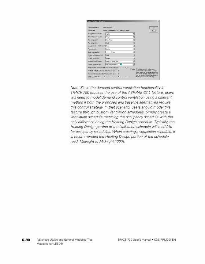
6 Go to Create Systems, click Advanced, and set the System
ventilation flag to Sum Room OA Reqs in the Baseline alternative to prevent the program from running multi-zone calculations of Standard 62.1-2007.
CDS-PRM001-EN_new.book Page 89 Friday, September 3, 2010 1:17 PM
6–90 Advanced Usage and General Modeling Tips TRACE 700 User’s Manual • CDS-PRM001-ENModeling for LEED®
Note: Since the demand control ventilation functionality in TRACE 700 requires the use of the ASHRAE 62.1 feature, users will need to model demand control ventilation using a different method if both the proposed and baseline alternatives require this control strategy. In that scenario, users should model this feature through custom ventilation schedules. Simply create a ventilation schedule matching the occupancy schedule with the only difference being the Heating Design schedule. Typically, the Heating Design portion of the Utilization schedule will read 0% for occupancy schedules. When creating a ventilation schedule, it is recommended the Heating Design portion of the schedule read: Midnight to Midnight 100%.
CDS-PRM001-EN_new.book Page 90 Friday, September 3, 2010 1:17 PM

6–91CDS-PRM001-EN • TRACE 700 User’s Manual Advanced Usage and General Modeling TipsModeling for LEED®
Select system typeAppendix G, Table G3.1.1A dictates the system type utilized and how to select the appropriate type for the baseline building.
Table 6–2 ASHRAE 90.1-2007 systems and the TRACE equivalent
Note: Applying the Appendix G baseline system requirements may be confusing. Refer to section G3.1.1 and Table G3.1.1A (to include notes) in ASHRAE 90.1-2007 plus the ASHRAE 90.1-2007 User’s Manual prior to selecting the appropriate system for selection criteria, exceptions, and number of baseline systems required. The number of rooms and zones assigned to a system in TRACE is critical to properly modeling the proposed and baseline alternatives. Fully understanding this is essential.
System requirementsAppendix G and the mandatory requirements found in Section 6 of ASHRAE 90.1-2007 set rules for determining whether various ECMs will be employed in the baseline building. Do not assume your baseline building does not include these items. Common control strategies are listed in the following table, along with references.
ASHRAE 90.1-2007 Appendix GBaseline System Equivalent TRACE 700 System
System 1 – PTAC Packaged Terminal Air Conditioner
System 2 – PTHP Incremental Heat Pump
System 3 – PSZ-AC Single Zone
System 4 – PSZ-HP Single Zone
System 5 – Packaged VAV with Reheat Variable Volume Reheat (30% Min Flow Default)
System 6 – Packaged VAV with PFP Boxes Parallel Fan Powered VAV
System 7 – VAV with Reheat Variable Volume Reheat (30% Min Flow Default)
System 8 – VAV with PFP Boxes Parallel Fan Powered VAV
CDS-PRM001-EN_new.book Page 91 Friday, September 3, 2010 1:17 PM

6–92 Advanced Usage and General Modeling Tips TRACE 700 User’s Manual • CDS-PRM001-ENModeling for LEED®
Note: This is not a complete list. ASHRAE 90.1-2007 is the primary source for determining if these or other control strategies are required in the baseline model.
Note: Some ASHRAE 90.1-2007 directed control strategies use airflow as a criteria in determining their use. If this is the case, calculate the Design portion of the baseline alternative to determine system level airflows (e.g. System Checksums report). Changes mentioned previously (e.g. envelope) should be made prior to calculation to ensure an accurate value is determined.
System fan sizingSystem fan energy for the baseline building is determined using a formula found in Appendix G. TRACE can automatically perform this calculation (for both ASHRAE Standard 90.1-2004 and 2007). This feature will determine the fan(s) location and accomplish the calculation at the appropriate level.
Strategy
TRACE User’s Manual page, or location in TRACE 700
ASHRAE Standard 90.1-2007 reference
Energy recovery page 4–15 G3.1.2.10
Demand control ventilation page 4–91 6.4.3.9
Airside economizer page 5–2 G3.1.2.6
Optimum start page 5–6 6.4.3.3.3
Supply air temperature reset page 5–50 G3.1.3.12
VAV minimum airflow requirement Create Templates or Create Rooms, Airflows tab
G3.1.3.13
Design airflow rates Create Systems, Temp/Humidity tab
G3.1.2.8
Fan cycling schedule Create Systems, Fans tab
6.4.3.3.1
CDS-PRM001-EN_new.book Page 92 Friday, September 3, 2010 1:17 PM

6–93CDS-PRM001-EN • TRACE 700 User’s Manual Advanced Usage and General Modeling TipsModeling for LEED®
Once the baseline system fan energy has been calculated, TRACE will apply this energy to the primary fan (if it is the only qualifying fan listed on the system). In the case when more than one fan has been entered for the system (e.g. exhaust fan), a portion of the system fan energy will be applied to each qualifying fan. The amount each fan receives is based on the Full Load
Energy Rate defined by the user for each baseline fan. The fan power ratio for the baseline must be the same as the proposed.
Note: ASHRAE 90.1-2007 considers most, but not all fans, in the baseline system fan energy calculation. Consult Appendix G to determine which fans are considered in the calculation.
To calculate system fan energy, follow the procedure below.
1 Check Apply ECB/PRM rules
to fan sizing.
2 Select the appropriate standard to be used for the calculation.
Note: When using the ASHRAE Standard 90.1- 2007 calculation method, define pressure drop adjustments on the Fans tab of Create Systems. If credit is taken for more than one pressure drop adjustment, total the number of pressure drop adjustments and enter that value.
3 To identify the baseline alternative, access the Calculate and View Results
screen. Select the baseline alternative using the drop-down menu for the Performance rating method.
CDS-PRM001-EN_new.book Page 93 Friday, September 3, 2010 1:17 PM

6–94 Advanced Usage and General Modeling Tips TRACE 700 User’s Manual • CDS-PRM001-ENModeling for LEED®
Note: Fan placement in TRACE depends on the system type selected.
■ Packaged Terminal Air Conditioners and Incremental Heat Pump systems have fans at the room level.
■ The Single Zone system has a fan at the zone level.
■ All VAV systems used to model Appendix G baseline systems have fans at the system level.
This distinction is important when analyzing the automatic fan sizing feature in TRACE. The system fan power is determined at the level of the primary fan. Therefore, the primary fan for an Incremental Heat Pump system is at the room level, which means that the equivalent Appendix G system fan power value will be calculated on a room-by-room basis for this system. Refer to “Zoning of rooms” on page 6–47 for more information.
Equipment designationAs with the system type, the type of equipment used in the baseline building is designated by Appendix G, Table G3.1.1B. Details regarding the particular equipment types can be found in Section 6 of ASHRAE Standard 90.1-2007. C.D.S. offers 90.1-
2004 and 90.1-2007 Minimally Compliant Equipment
Libraries, which include the equipment found in these tables.
Before selecting equipment, the baseline equipment capacities need to be determined (equipment types are categorized by size in ASHRAE 90.1-2007, Section 6). Appendix G requires both the cooling and heating capacities in the baseline building be oversized. (See “Oversizing plants” on page 6–95.) Once baseline capacities are determined, select the appropriate equipment from the tables in Section 6 of ASHRAE 90.1-2007.
CDS-PRM001-EN_new.book Page 94 Friday, September 3, 2010 1:17 PM

6–95CDS-PRM001-EN • TRACE 700 User’s Manual Advanced Usage and General Modeling TipsModeling for LEED®
Oversizing plantsOne of the often overlooked Appendix G requirements for the baseline building is the requirement to oversize cooling plants by 15 percent and the heating plants by 25 percent. TRACE offers two methods for modeling oversizing. Choose only one of these methods.
■ Method 1: Oversize the coils (Recommended)
■ Method 2: Oversize the plants
Method 1: Oversize the
coils.
1 In Create Systems, select the Coils tab.
2 Oversize the cooling and heating coils as shown.
Oversizing the coils will automatically carry over to the equipment section and size the plants appropriately. Additionally, this method increases the design sizing of the equipment. Users will see this reflected in the design reports (e.g., System
Checksums).
Oversize cooling by 15%.
Note: The capacity units for Main
Cooling and Main Heating must be % of Design Cooling Capacity and % of Design Capacity, respectively.Oversize heating by 25%.
Note: In TRACE 700, the main and reheat coils are the same. It is only necessary to oversize the main coil.
CDS-PRM001-EN_new.book Page 95 Friday, September 3, 2010 1:17 PM

6–96 Advanced Usage and General Modeling Tips TRACE 700 User’s Manual • CDS-PRM001-ENModeling for LEED®
Compressor-only energy rateIn TRACE, the Energy rate entry under the Cooling Equipment
tab of Create Plants describes the compressor-only energy rate for the piece of equipment. This is important because the efficiency reported for packaged systems (e.g., rooftops, water source heat pumps, packaged terminal air conditioners, etc.) often includes fan, condenser, and compressor efficiencies.
Users may enter the EER or COP value found in the ASHRAE 90.1-2007 equipment tables and define which components are included in the energy value. TRACE will use this information along with the associated component energy values to break out the compressor values for the equipment calculation.
Method 2: Oversize the
plants
Note: Unlike Method 1, this method does not affect the design sizing, but instead adds capacity.
1 Check the Link airside
coil capacities to
equipment capacities box.
2 On the Create Plants -
Cooling Equipment tab, select % Plant Capacity and enter 115 for oversizing.
3 On the Create Plants -
Heating Equipment tab, select % Plant Capacity and enter 125 for oversizing.
Note: If multiple pieces of equipment are included in one plant, the total of the equipment capacities should not exceed the oversizing amount. For example, a chiller plant consisting of two same-sized chillers would set each chiller to 57.5% for a total plant capacity of 115%.
CDS-PRM001-EN_new.book Page 96 Friday, September 3, 2010 1:17 PM

6–97CDS-PRM001-EN • TRACE 700 User’s Manual Advanced Usage and General Modeling TipsModeling for LEED®
Users may also manually break out the efficiency into the individual packaged components. If the manual method is used, the individual component energy rates need to be defined in the appropriate place.
1 Fan energy rates are accounted for in Create Systems under the Fans tab.
2 Condenser energy rate is entered with the associated piece of heat rejection equipment in the Heat Rejection library.
3 Compressor energy rate is entered on the Cooling Equipment tab of Create Plants.
ExampleUtilizing ASHRAE Standard 90.1-2007, System 5 supply cfm equals 45,000 and the Appendix G designated packaged equipment efficiency is 9.5 EER (Table 6.8.1A). Additionally, the building requires 150 tons of cooling. Users may run the design portion of the calculation for the baseline building and then use the System Checksum Report(s) to determine building cooling capacity and cfm. Using this information and Appendix G, users may now break out the compressor energy rate from the given 9.5 EER.
Steps 1 and 2 illustrate the manual system fan power calculation per section G3.1.2.9 of ASHRAE Standard 90.1-2007. As discussed previously, TRACE can accomplish this calculation automatically. Users may obtain the system fan power value from
CDS-PRM001-EN_new.book Page 97 Friday, September 3, 2010 1:17 PM

6–98 Advanced Usage and General Modeling Tips TRACE 700 User’s Manual • CDS-PRM001-ENModeling for LEED®
the Equipment Energy Consumption Report if they wish to take advantage of this feature. If this is done, skip to step 3.
1 Determine the system fan brake horsepower using Table G3.1.2.9. In this case, System 5 is a variable-volume system with 45,000 cfm total supply air.
According to Table G3.1.2.9:
Baseline Fan Motor Brake Horsepower =
CFMS x 0.0013 + A
Where A is calculated per section 6.5.3.1.1:
A = sum of (PD x CFMD / 4131)
Where PD equals each applicable pressure drop adjustment from Table 6.5.3.1.1B
Assume “Fully ducted return and/or exhaust air systems”; therefore, per the Table:
PD = 0.5 in. w.c.
Thus,
A = 0.5 x 45,000 / 4131 = 5.45
Applying this to the Baseline Fan Motor Brake Horsepower formula:
45,000 x 0.0013 + 5.45 = 63.95 bhp
2 Next, calculate the system fan power using the formula found in section G3.1.2.9 and the system brake horsepower from step 1.
System Fan Power equation for systems 3 through 8:
Pfan = bhp x 746 / Fan Motor Efficiency
Where the Fan Motor Efficiency is from Table 10.8(Select the next motor size greater than the bhp from step 1 per enclosed motor at 1800 rpm)
(63.95 x 746) / 0.941 = 50,698 W ≈ 50.7 kW
CDS-PRM001-EN_new.book Page 98 Friday, September 3, 2010 1:17 PM
6–99CDS-PRM001-EN • TRACE 700 User’s Manual Advanced Usage and General Modeling TipsModeling for LEED®
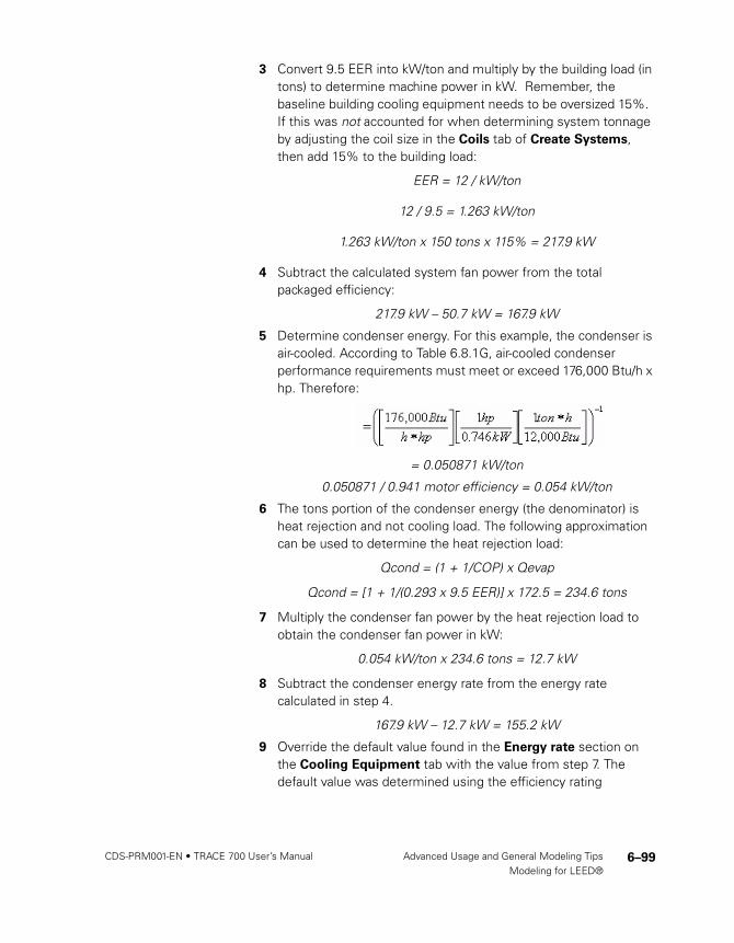
3 Convert 9.5 EER into kW/ton and multiply by the building load (in tons) to determine machine power in kW. Remember, the baseline building cooling equipment needs to be oversized 15%. If this was not accounted for when determining system tonnage by adjusting the coil size in the Coils tab of Create Systems, then add 15% to the building load:
EER = 12 / kW/ton
12 / 9.5 = 1.263 kW/ton
1.263 kW/ton x 150 tons x 115% = 217.9 kW
4 Subtract the calculated system fan power from the total packaged efficiency:
217.9 kW – 50.7 kW = 167.9 kW
5 Determine condenser energy. For this example, the condenser is air-cooled. According to Table 6.8.1G, air-cooled condenser performance requirements must meet or exceed 176,000 Btu/h x hp. Therefore:
= 0.050871 kW/ton
0.050871 / 0.941 motor efficiency = 0.054 kW/ton
6 The tons portion of the condenser energy (the denominator) is heat rejection and not cooling load. The following approximation can be used to determine the heat rejection load:
Qcond = (1 + 1/COP) x Qevap
Qcond = [1 + 1/(0.293 x 9.5 EER)] x 172.5 = 234.6 tons
7 Multiply the condenser fan power by the heat rejection load to obtain the condenser fan power in kW:
0.054 kW/ton x 234.6 tons = 12.7 kW
8 Subtract the condenser energy rate from the energy rate calculated in step 4.
167.9 kW – 12.7 kW = 155.2 kW
9 Override the default value found in the Energy rate section on the Cooling Equipment tab with the value from step 7. The default value was determined using the efficiency rating
CDS-PRM001-EN_new.book Page 99 Friday, September 3, 2010 1:17 PM

6–100 Advanced Usage and General Modeling Tips TRACE 700 User’s Manual • CDS-PRM001-ENModeling for LEED®
associated with the particular piece of equipment per Tables 6.8.1 from the 2004 standard. As long as the previous steps were followed utilizing values from the 2007 standard, the value from step 7 will make the selected equipment compliant with the 2007 standard.
Additional equipment considerationsAs with the baseline building systems, Appendix G dictates additional equipment requirements based on the system type. Following is a list of additional equipment requirements that may need to be included. Many of the equipment types found in the 90.1-2004 and 90.1-2007 Minimally Compliant Equipment
Libraries contain their applicable requirements.
Note: This is not a complete list. ASHRAE 90.1-2007 is the primary source for determining if these or any other equipment requirements exist.
■ Type and number of boilers
■ Type and number of chillers
■ Heat pump requirements
■ Hot water reset
■ Chilled water reset
■ Pump requirements
Utility rate structuresUse the same rate used in the proposed alternative.
Calculating the fileAppendix G requires the baseline building be rotated in four directions, with the report of the results to include the average of the four rotations. TRACE includes an automatic rotation feature that satisfies this requirement. Users may access this feature through Calculate and View Results by selecting the Rotate
and Average PRM Results checkbox. As with the fan sizing feature, TRACE applies the automatic rotation to the alternative designated in the drop-down menu for the Performance Rating
Method.
Note: Calculation time will increase significantly when this option is chosen because the simulation must run for each direction.
CDS-PRM001-EN_new.book Page 100 Friday, September 3, 2010 1:17 PM

6–101CDS-PRM001-EN • TRACE 700 User’s Manual Advanced Usage and General Modeling TipsModeling for LEED®
Completing the analysisAfter calculating the baseline alternative, the proposed and baseline results should be compared. The LEED Energy
Performance Summary Report provides results in a format similar to the EAp2 and EAc1 templates (for both version 2.2 and version 3). If the baseline energy cost is less than the proposed, further analysis is required. Consider these three basic steps when determining potential causes:
■ Identify areas where the baseline consumes more energy (e.g. space heating, space cooling, fans)
■ Verify inputs for these areas (e.g. crosscheck ASHRAE 90.1-2007 requirements)
■ Verify proposed design inputs (e.g. schedules, envelope)
If the baseline alternative energy cost is greater, verify the unmet hours for both alternatives comply with the ASHRAE 90.1-2007 requirement. If the unmet hours do not comply with the requirement, review the following for methods of reducing or eliminating them.
Unmet hoursUnmet load hours are triggered in TRACE when space conditions are outside the thermostat setpoints. Unmet hours occur for a wide variety of reasons. They are restricted to hours when the excess load on a coil is at least 1 percent greater than the design coil capacity, and at least one room attached to that coil is in excess of 1.5°F of the thermostat setpoint for that hour.
CDS-PRM001-EN_new.book Page 101 Friday, September 3, 2010 1:17 PM

6–102 Advanced Usage and General Modeling Tips TRACE 700 User’s Manual • CDS-PRM001-ENModeling for LEED®
Strategies that may help reduce or limit the number of unmet load hours are presented below. The different approaches target commonly overlooked assumptions in the TRACE data entry process, as well as the complex interactions that typically occur in building simulations. Each building model is unique, and as such, the impact of each approach may be different. In some cases, the number of unmet load hours may even increase. It is
important to understand the underlying cause of the loss of
space control rather than arbitrarily adjusting data entries to
reduce or eliminate the unmet hours.
Note: These strategies may increase the building model's total energy consumption for various reasons.
Step #1 – Identify unmet hours The Energy Cost Budget / PRM Summary report provides the total, simultaneous number of cooling and heating unmet hours per alternative. Although this provides a good overview regarding problematic alternatives, refer to the Building Temperature
Profile report for a detailed accounting of unmet hours. This report lists rooms (by system) showing the number of cooling and heating unmet hours associated with each. A section of the report displays the time-of-day, daytype, and month the unmet hours occur. This information can help identify potential causes for the unmet hours. For example, if a space consistently has unmet load hours on Mondays around the time occupancy begins, an optimum start schedule may help eliminate those hours due to pull-up/pull-down loads.
Note: The unmet load hours that are displayed in the Building
Temperature Profile report are not additive because any one space can trigger an unmet load hour, but if multiple spaces have unmet conditions for the same hour, then only a single hour is tallied. This means that there are a total of 8760 unmet load hours possible for either heating or cooling.
Step #2 – Review inputs Once the problem areas have been identified, focus on the data entry process. The Scan for Errors feature (found through Calculate and View Results) reports many of the items discussed below. Utilizing this feature (particularly prior to calculating) will help identify potential errors. Keep in mind many
CDS-PRM001-EN_new.book Page 102 Friday, September 3, 2010 1:17 PM

6–103CDS-PRM001-EN • TRACE 700 User’s Manual Advanced Usage and General Modeling TipsModeling for LEED®
of the results are simply warnings and do not necessarily require action … only your attention to ensure the model was set up as intended.
■ Verify that design and simulation schedule assumptions are accurate.
Perhaps the single largest area of uncertainty in a building simulation model occurs in the scheduling of internal loads. TRACE allows you to differentiate design and simulation internal load schedules for proper coil sizing. If the design schedules are too moderate, coils could be undersized. Alternatively, if the simulation schedules are overly conservative, this could also lead to undersized coils due to dynamic building changes that are not accounted for during design calculations.
■ Verify correct thermal zoning and thermostat placement.
Proper thermal zoning of spaces, as well as properly modeling thermostat locations, is vital to proper building simulation. Ensure spaces are properly zoned per design documents and are modeled correctly in the Assign Rooms to Systems section.
■ Verify accuracy of drift point entries or thermostat schedules.
When a space is unoccupied (less than 5 percent occupancy) and there is no thermostat schedule applied, drift temperatures are used as the thermostat setpoints. If there is a wide variance between the occupied setpoint and the drift point, the HVAC equipment may not be able to handle the pull-up or pull-down load in the one-hour time increment as the building becomes occupied. Verify the temperatures entered are an accurate representation of the actual building thermostat controls. The same suggestion applies when utilizing thermostat schedules. However, realize thermostat schedules are not affected by occupancy like drift points. Instead, they follow the user-defined schedule.
■ Limit restrictions to fan operation.
TRACE has fan control options allowing the program to intelligently cycle the fan to meet changing load conditions. Avoid scheduling fans manually because the simulation may not match up with the expected fan operation schedule. Leaving the fan schedules set to Available (100%) and applying a fan cycling
CDS-PRM001-EN_new.book Page 103 Friday, September 3, 2010 1:17 PM

6–104 Advanced Usage and General Modeling Tips TRACE 700 User’s Manual • CDS-PRM001-ENModeling for LEED®
schedule provides the most accurate method for controlling the fan operation. Scheduling a fan as something other than Available (100%) can quickly lead to a high number of unmet load hours.
■ Verify that diversity has been accurately defined.
One way to reduce design coil capacity for VAV systems is to apply a diversity factor for internal loads. This factor allows you to credit VAV system capacity for shifting loads in a building (e.g., each space has to be designed to handle its worst case loads, but at any given point in time there are less than design internal loads in the building). If the diversity factors are overly optimistic and do not mesh with the occupancy schedules for simulation, coils could be undersized. This approach does not apply to constant volume systems. To access the diversity input, go to the Coils tab of Create Systems.
■ Apply an optimum start schedule.
TRACE design coil capacities are determined at steady state conditions assuming the space is always controlled to the desired design space setpoint. In some instances, pull-up or pull–down loads associated with dynamic building operation can exceed the capacity of a coil. These dynamic conditions are not accounted for in the design process. A common example of when this might occur is when a building has night setback thermostat controls that allow the building to drift during unoccupied hours. When the building becomes occupied, the design coil capacity may not be large enough to condition the space(s) to the desired setpoint in a single hour, thus triggering unmet load hours. Applying this control strategy allows the building automation system to condition the spaces in advance in order to reach the desired setpoint when the building becomes occupied. ASHRAE Standard 90.1-2004 and 2007 require optimum start controls to be modeled for systems larger than 10,000 cfm.
It is recommended that users select the Available (100%) schedule for the optimum start schedule. Doing so will allow the program to activate the system as early as is necessary to maintain space control (if possible) under pull-up or pull-down situations.
CDS-PRM001-EN_new.book Page 104 Friday, September 3, 2010 1:17 PM
6–105CDS-PRM001-EN • TRACE 700 User’s Manual Advanced Usage and General Modeling TipsModeling for LEED®
Note: Only an optimum start schedule is needed to combat unmet hours, not an optimum stop schedule.
Step #3 – Additional considerationsIf the preceding strategies did not resolve your unmet load hours issue, investigate the following items.
■ Verify envelope parameters (walls, floors, roofs, etc.) are correctly defined.
TRACE considers the thermal mass effects of the building’s envelope. Typically, loads in a high mass building will peak later (and at a lower value) than loads in a low mass building. Incorrectly defining envelope parameters will have an impact on the program’s ability to accurately calculate the thermal mass effects of the building. If you choose to create custom elements (e.g. walls, roofs, floors), be sure to correctly define the library value. Remember, construction types should always begin with outside/inside surface resistance and end with the opposite outside/inside surface resistance.
■ Verify correct application of ASHRAE Standard 62.1 in TRACE.
When modeling ASHRAE Standard 62.1 in TRACE, ensure the feature is activated on both the Create Rooms - Airflows tab and Create Systems - Selection tab (Advanced button). Doing so ensures an accurate ventilation load calculation. See “ASHRAE Standard 62.1” on page 4–91 for more information.
■ Utilize an appropriate ventilation schedule.
Users often wish to schedule ventilation to follow the occupancy schedule. The concept is sound, but incorrectly modeling this causes problems. The standard occupancy schedules in TRACE do not work well for ventilation. Since ASHRAE recommends not taking credit for internal heat gains, standard occupancy schedules in TRACE set the heating design schedule values to 0 percent. When used as a ventilation schedule, the 0 percent value for heating design exempts ventilation from the heating design calculation. Instead, a more conservative approach would be to utilize a standard TRACE ventilation schedule. If you view the standard ventilation schedule with its corresponding standard occupancy schedule, you will see the only difference is the heating design value is set to 100 percent for ventilation.
CDS-PRM001-EN_new.book Page 105 Friday, September 3, 2010 1:17 PM

6–106 Advanced Usage and General Modeling Tips TRACE 700 User’s Manual • CDS-PRM001-ENModeling for LEED®
Similarly, using a ventilation schedule of Available (100%) may not always be appropriate. Depending on code requirements, introducing ventilation only during occupied periods can provide substantial energy savings. Utilizing the Available (100%) schedule brings ventilation air into the space 24/7 unless ASHRAE Standard 62.1 with ventilation reset control is enabled.
■ Check VAV airflow.
Typically this occurs with VAV systems and manifests as unmet heating hours. Since heating airflow is limited by the minimum stop of a VAV box, sufficient airflow may not reach the space to satisfy the load. You can detect this by reviewing the Room
Checksums report. If the heating supply temperature appears unusually high, consider increasing the VAV minimum for the space. Likewise, if the space does not receive the required ventilation during heating due to the minimum stop, select Actions > Change Load Parameters from the menu bar. On the Change Load Parameters screen, check the Force VAV
minimum always >= nominal ventilation during design box. This will adjust the VAV minimum automatically to ensure the space receives the defined amount of ventilation.
■ Correctly define the return air path.
Those modeling spaces without plenums often forget to change the return air path from Plenum to Ducted. To do so, go to the Create Systems – Selections tab and select the Advanced button. Making this change ensures TRACE does not calculate a plenum temperature. Not doing so could result in additional load on the system.
If you have a situation where some rooms on the system do have a plenum and some do not, you can do one of two things: you can define a one-foot plenum for those rooms not having one, or you can place the rooms without plenums on a separate system.
■ Verify coil sizing and scheduling.
Much like with fan scheduling, applying a schedule other than Available (100%) can quickly lead to a high number of unmet load hours. In other words, if TRACE needs the coil to satisfy a load and the coil is scheduled off, then the load will not be satisfied and will be carried over to the next hour. Likewise, undersizing coils or turning coils off can lead to unmet hours.
CDS-PRM001-EN_new.book Page 106 Friday, September 3, 2010 1:17 PM

6–107CDS-PRM001-EN • TRACE 700 User’s Manual Advanced Usage and General Modeling TipsModeling for LEED®
Step #4 – Increase capacityIf all other approaches fail, consider increasing the system coil or plant capacity in an attempt to reduce unmet load hours.
Increase the appropriate coil capacities on the Create Systems –
Coils tab. This may be an iterative process if the desired increase in capacity has a limited effect on the number of unmet hours.
Note: Coil capacities will automatically be carried over to the plants they are assigned to, thus increasing the plant size automatically. Changing equipment capacities under the Create
Plants section of the program has no impact on the system simulation unless you have checked the box to link the equipment capacity to the system coil capacities on the Change
Energy Parameters screen. If you have already adjusted the capacities of the coils in the Create Systems section, the plant linking feature should not be utilized. Generally, the equipment capacities are only used for energy calculations.
It is important to verify the increase in capacity is realistic given the building design properties.
LEED template submittalThe LEED version 3 EAp2 and EAc1 templates provide guidance on the reports to include with the submittal. Aside from those required, the following reports provide information reviewers may find helpful.
■ Room Information from Entered Values reports
■ Plant Information from Entered Values reports
■ Library Information from Entered Values reports
■ System Checksums from Design Reports
■ LEED Energy Performance Summary Report from Analysis Reports
■ PRM Fan Details from Analysis Reports
Additional LEED creditsTRACE can help provide information to qualify for additional LEED credits. For example, under the LEED New Construction version 3 rating structure, TRACE may help with the following credits:
CDS-PRM001-EN_new.book Page 107 Friday, September 3, 2010 1:17 PM

6–108 Advanced Usage and General Modeling Tips TRACE 700 User’s Manual • CDS-PRM001-ENModeling for LEED®
Energy and Atmosphere prerequisite 2 (EAp2):
Minimum Energy PerformanceThis prerequisite for achieving LEED certification requires the proposed building meet a minimum standard of energy efficiency.
Energy and Atmosphere credit 1 (EAc1), option 1:
Optimize Energy PerformanceTRACE 700 provides many features that help evaluate a building’s overall energy use and determine its efficiency. These features are discussed in length during the C.D.S. ASHRAE Standard 90.1/LEED seminar. Contact C.D.S. for more information regarding this training class.
Energy and Atmosphere credit 5 (EAc5), option D:
Measurement & VerificationThe model used for EAc1 can be used towards achieving this credit. Reference the “International Performance Measurement & Verification Protocol: Concepts and Options for Determining Energy Savings in New Construction Volume III” for detailed information on how to appropriately adjust the model from EAc1 to be used for this credit.
Energy and Atmosphere credit 6 (EAc6): Green PowerThe model used for EAc1 can identify the baseline electrical consumption needed to achieve Green Power credits.
Water Efficiency credit 2 (WEc2): Innovative
Wastewater TechnologiesThe Equipment Energy Consumption report shows the amount of make-up water associated with the cooling coil condensate. This information may be helpful in achieving this credit.
Indoor Environmental Quality prerequisite 1 (EQp1):
Minimum Indoor Air Quality PerformanceTRACE 700 conducts the ASHRAE 62.1-2007 calculation per user defined rates and effectiveness values. The ASHRAE Std 62.1-
2004/2007 report details calculation results aiding the user in their efforts to optimize the design.
CDS-PRM001-EN_new.book Page 108 Friday, September 3, 2010 1:17 PM

6–109CDS-PRM001-EN • TRACE 700 User’s Manual Advanced Usage and General Modeling TipsModeling for LEED®
Indoor Environmental Quality credit 2 (EQc2):
Increased VentilationTRACE 700 allows users to define the outdoor air ventilation rates for the ASHRAE 62.1 calculation. By manually increasing the ASHRAE 62.1 outdoor air ventilation rate 30%, showing compliance with this credit is simplified.
Indoor Environmental Quality credit 8.1 (EQc8.1):
Daylighting & ViewsCredits are awarded when a specified level of daylighting is achieved. When users create daylighting definitions within TRACE, the program generates a special report showing the footcandles of daylight present in the spaces with daylighting controls.
CDS-PRM001-EN_new.book Page 109 Friday, September 3, 2010 1:17 PM