Embed Size (px)
DESCRIPTION
v
Citation preview
Design and fabrication of a Remotely Operated
Under-water Vehicle
CONCEPT DESIGN AND REVIEW BOARD
REPORT
Group members
Siddi Abdullah Faiz
Advisor
Dr. Hammad I. Sherazi
Muhammad Bilal Bawany
Saad Bin Shakil
Ehtisham
Pakistan Navy Engineering College
National University of Sciences and Technology
2
DESIGN AND FABRICATION OF AN ROV
Table of ContentsAim of project........................................................................................................................................5
Problem Statement:..........................................................................................................................5
Scope:................................................................................................................................................5
Historical perspective............................................................................................................................6
Literature Review:.............................................................................................................................6
Recent Progress:................................................................................................................................6
Principles of an ROV..............................................................................................................................7
Classification of ROVs:.......................................................................................................................7
Functions of ROVs:.............................................................................................................................8
Buoyancy:..........................................................................................................................................9
Stability:...........................................................................................................................................10
Drag:................................................................................................................................................12
Pressure:..........................................................................................................................................13
Design Parameters...............................................................................................................................13
Material Selection:...........................................................................................................................13
Diving and surfacing mechanism:....................................................................................................15
Propulsion Mechanism:...................................................................................................................18
Motor..............................................................................................................................................19
Propeller..........................................................................................................................................19
Control Systems...................................................................................................................................20
Depth Sensor...................................................................................................................................20
.............................................................................................................................................................21
Temperature Sensor:...........................................................................................................................22
Pressure Sensor:..............................................................................................................................22
Design Specifications...........................................................................................................................23
Project Risk Assessment......................................................................................................................26
Risk Statement:................................................................................................................................27
Project Cost Assessment......................................................................................................................28
Bibliography.........................................................................................................................................29
Appendix - A........................................................................................................................................31
2
DESIGN AND FABRICATION OF AN ROV
GANNT CHART.................................................................................................................................31
.............................................................................................................................................................32
Appendix - B........................................................................................................................................33
Statement of Requirement..............................................................................................................33
List of TablesTable 1 Material Feature Requirement...............................................................................................14Table 2 - Weighted Matrix...................................................................................................................14Table 3 – Rating matrix........................................................................................................................14Table 4 Diving Mechanism Comparison (University of Canterbury)..................................................15Table 5 Required features...................................................................................................................17Table 6 Weighted Matrix....................................................................................................................17Table 7 - Rating Matrix........................................................................................................................17Table 8 Risk Assessment......................................................................................................................26Table 9 Cost Assessment.....................................................................................................................28
List of FiguresFigure 1: A Royal Navy ROV (Cutlet) first used in the 50's.....................................................................6Figure 2: Buoyancy Forces (Creative Commons)................................................................................9Figure 3 a) Stable equilibrium b) Unstable equilibrium c) Neutral Equilibrium (IIT Kanpur) 11Figure 4 System drag components (The ROV Manual).......................................................................12Figure 5 Variation of total drag and its components with tether length / depth (The ROV Manual)...12Figure 6: Piston Ballast Tank mechanism (IIT Kharagpur)..................................................................16Figure 7 Different thruster arrangements (the ROV manual)......................................................18Figure 8 - Control system flowchart.....................................................................................................20Figure 9 Sensor interfaced with the microcontroller (Carnegie Mellon Robotics Academy)...............21Figure 10 – Thermocouple (REOTEMP Instrument Corporation).........................................................22Figure 11 Box type design of ROV (3D CAD browser)..........................................................................24Figure 12 Concept ROV (Grab CAD).....................................................................................................25
2
DESIGN AND FABRICATION OF AN ROV
List of Symbols and abbreviations
ROV = Remotely Operated Underwater Vehicle
COG= Center of Gravity
COB= Center of Buoyancy
BG = Buoyancy Gradient
M = Moment
W = Weight of ROV
ρ = Density of water
A = Frontal area of ROV
V= Velocity of ROV
Cd = Co-efficient of drag

2
DESIGN AND FABRICATION OF AN ROV
Aim of projectMarine mapping has become an important concern for many industries such as Oil & Gas, Military and academic research of the marine environment. The availability of oceanic data is the cornerstone of most oceanographic studies. Even today a majority of our ocean floors remain unmapped because the cost and hazards of sending manned underwater missions to gather oceanic data far outweigh its benefits.
Problem Statement:Despite roughly three-quarters of the earth being covered by water, large areas of the ocean remain unmapped. In the present day, the importance and requirement of oceanography has taken utmost importance in the field of marine biology, chemistry, geology and engineering. The oceanographers compile and study this data to investigate ecology of marine environment, chemical interaction of the ocean and marine physics. In order to complete these tasks, oceanographers require well-mapped areas of the ocean with complete knowledge of the aquatic environment.
Previously, sub-sea manned vessels were employed to accomplish the task of marine mapping. This was a time consuming and costly process. It required fuel, food supplies, larger vessels, higher electricity consumption and the under-water time period was limited.
By creating a prototype Remotely Operated Underwater vehicle capable of providing oceanic data, we aim to test an innovative concept which significantly reduces the cost and hazards that have previously been associated with marine mapping.
Scope:The scope of this project is to design and fabricate a prototype Remotely Operated Under-water vehicle that is maneuverable directions underwater and is capable of gathering and compiling specified oceanic data.
2
DESIGN AND FABRICATION OF AN ROV
Historical perspective
Literature Review:
There is ambiguity as to who invented the first ROV, however much of the credit for its creation goes to:
A) Luppis-Whitehead Automobile in Austria in 1864, who developed a torpedo name PUV (Programmed Underwater Vehicle)
B) The first tethered ROV, named POODLE, was developed by Dimitri Rebikoff in 1953.
C) The development of ‘Cutlet’ in the 1950s, the royal Navy used to recover torpedoes.
After these three, the advancement of the ROV is largely credited to the US Navy. The US Navy sponsored most of the early ROV technology development in the 1960s and developed "Cable-Controlled Underwater Recovery Vehicle" (CURV). This was a working class ROV created to perform deep-sea rescue and recovery operations. Two of its most successful operations were the recovery of a nuclear bomb lost in the Mediterranean Sea after the 1966 Palomares B-52 crash and the rescue of pilots from a sunken submersible off Cork, Ireland, the Pisces in 1973.
Due to the success of the navy with ROVs, commercial firms started taking interest in their development. Oil and gas companies saw an opportunity on working with ROVs to support offshore drilling. The first two offshore ROVs built were RCV-225 and the RCV-150, developed by Hydro Products in the U.S. Other companies were also engaged in the development of new and more efficient ROVs.
After this early success of the ROV, the development suffered a set-back during the mid-1980s due to a reduction in oil prices and global economic recession. Since then, the ROV has enjoyed gradual progress in the improvement of its technology and versatility of its functions.
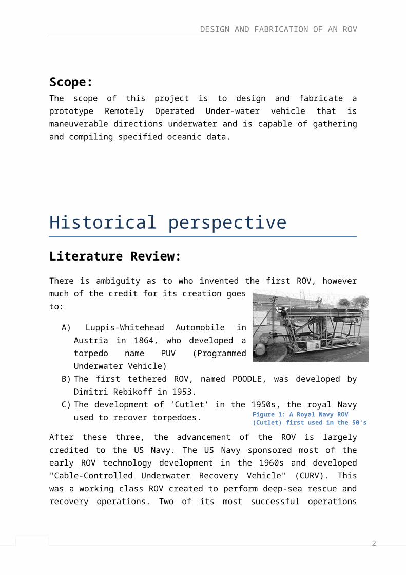
Recent Progress:Organizations such as Mitsui and JAMSTEC in Japan have taken ROV development to new heights. They claim to achieve depths of more than 10,000 meters, which now means that nothing is out of reach in the depths of the ocean. With the development of their ultra-deep ROV Kaiko, they have reached the deepest part of
Figure 1: A Royal Navy ROV (Cutlet) first used in the 50's
2
DESIGN AND FABRICATION OF AN ROV
the ocean - the Challenger Deep in the Mariana Trench, at a record of 10,909 meters.
The development in the technology has made the size of ROVs even smaller which enables operation at shallow depths and low costs, like the phantom and Mini- rover. These vehicles provide more efficiency, and are feasible economically as well as in their maneuverability.
Principles of an ROVAn ROV is essentially a robot that performs specified tasks underwater, while its operator remains above sea level. The vehicle is connected to the surface by an umbilical or tether. ROVs are available in a wide variety of function capabilities with a wide range of variations in design and structure.
Classification of ROVs:
Class I – Pure observation Pure observation vehicles perform visual observation through the use of video cameras. Usually they are small and have high maneuverability. They cannot undertake any other task without considerable modification.
Class II – Observation with payload option
Class II A – Observation class vehicles with payload option These are vehicles capable of carrying additional sensors such as pressure sensors, temperature sensors, additional video cameras and sonar systems.
Class II B – Observation class vehicles with survey and light construction capabilities In addition to the functionalities of Class II A vehicles, Class II B vehicles are also capable of carrying light working manipulators and tooling kits. The vehicle is able to perform light construction, intervention, and survey tasks.
Class III – Work class vehicles Vehicles large enough to carry additional sensors and tooling, through frame lift capability and full size manipulators. Class III vehicles commonly have a multiplexing capability which eliminates the need for ‘hardwiring’ of every component.
2
DESIGN AND FABRICATION OF AN ROV
Class III A – Work class vehicles typically < 100 kW. A compact ROV with typical capability up to 2000 kg through frame lift and pay load up to 200 kg.
Class III B – Work class vehicles typically >100 kW A larger ROV with typical capability more than 2000 kg through frame lift and pay load more than 200 kg.
Functions of ROVs:
Diver ObservationEnsures diver safety.
Platform and Pipeline InspectionPerforms visual inspection and uses instrumentation to test for harmful effects such as corrosion. Also, checks the rigidity and performs leak detection exercise on under water pipes.
SurveysPerforms visual and acoustic surveys prior to commissioning of offshore installations. Marine mapping Gathers and transmits aquatic environment data for use in oceanography.
Debris RemovalOffshore platforms can collect trash and dirt underwater. ROVs are a simple and economical solution of keeping them clean and safe.
Drilling and Construction SupportPerforms visual inspection, monitoring installation and uses multiple manipulators to provide operational support.
Platform cleaning and Debris RemovalROVs provide a cost effective method of keeping offshore platforms clean and safe. Subsea InstallationsSupport the construction, operation, inspection, maintenance and repair of subsea installations.
Telecommunications Support ROVs can locate, follow, retrieve and re-bury subsea telecommunication cables.
2
DESIGN AND FABRICATION OF AN ROV
Mine Countermeasures Used by the navy to disarm underwater mines.
Object Location and RecoveryExecute search, location, and recovery of lost objects.
Before selecting the type and class of the ROV, its aim and functionality needs to be determined. After the selection of the class, the design of the ROV depends on the following parameters:
Cost Market size, requirements and acceptability Operational platform (e.g. ships, rigs, platforms, etc.) Available technology Power Size Weight Maximum depth Sea state Payload capability Application Versatility (i.e. configurability for different tasks) Safety Reliability Maintainability
Important Concepts:
Buoyancy:
Buoyancy is an upward force exerted by a fluid that opposes the force exerted by the weight of the immersed object. An important principle governs this phenomenon:
Archimedes Principle states that an object wholly or partially immersed in a liquid is held up by a force (buoyancy) equal to that of the weight of the water it displaces.
There are three types of buoyancy:
Figure 2: Buoyancy Forces (Creative Commons)
2
DESIGN AND FABRICATION OF AN ROV
Positive Buoyancy:
Positive buoyancy occurs when the object is lighter than the fluid it displaces. Thus, the buoyant force is greater than the object’s weight and a net upward force acts on the body.
Negative Buoyancy:
Negative buoyancy occurs when the object is heavier/denser than the liquid it displaces. Thus, the weight of the object is greater than the buoyant force and a net downward force acts on the body.
Neutral Buoyancy:
Neutral buoyancy occurs when an object's weight is equal to the fluid it displaces. Thus, the object floats.
ROVs may generally be either positively buoyant or negatively buoyant depending on their application.
Stability:
In submerged vehicles like the ROV, rotational stability is the most important consideration because the pressure, buoyancy and gravitational forces keep the ROV vertically and horizontally stable. The design of the ROV determines its rotational stability.
Rotational stability is determined by the assessment of the moment required to change the pitch angle of the vehicle, characterized by the equation:
M=W (BG )sinθ
It is clear from the equation that a large distance between the center of gravity and center of buoyancy will provide a more stable vehicle. In general, the greater the distance between the COB and the COG, the more stable the vehicle and the more likely it is to remain upright. However, a smaller distance between COG and COB results in a less stable but more maneuverable vehicle. An ROV which has the COB and COG in the same spot is expected to be highly maneuverable, but will be unstable in pitch and roll.
2
DESIGN AND FABRICATION OF AN ROV
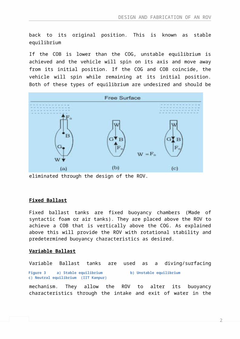
In an ROV, the COG should always be lower than the COB, so that the when external forces tilt the vehicle, it will return back to its original position. This is known as stable equilibrium
If the COB is lower than the COG, unstable equilibrium is achieved and the vehicle will spin on its axis and move away from its initial position. If the COG and COB coincide, the vehicle will spin while remaining at its initial position. Both of these types of equilibrium are undesired and should be eliminated through the design of the ROV.
Fixed Ballast
Fixed ballast tanks are fixed buoyancy chambers (Made of syntactic foam or air tanks). They are placed above the ROV to achieve a COB that is vertically above the COG. As explained above this will provide the ROV with rotational stability and predetermined buoyancy characteristics as desired.
Variable Ballast
Variable Ballast tanks are used as a diving/surfacing mechanism. They allow the ROV to alter its buoyancy characteristics through the intake and exit of water in the tank. It also has the added benefit of providing the ROV with rotational stability while diving in high ocean currents by adding additional weight and hence lowering the COG.
Figure 3 a) Stable equilibrium b) Unstable equilibrium c) Neutral equilibrium (IIT Kanpur)
2
DESIGN AND FABRICATION OF AN ROV
Drag:
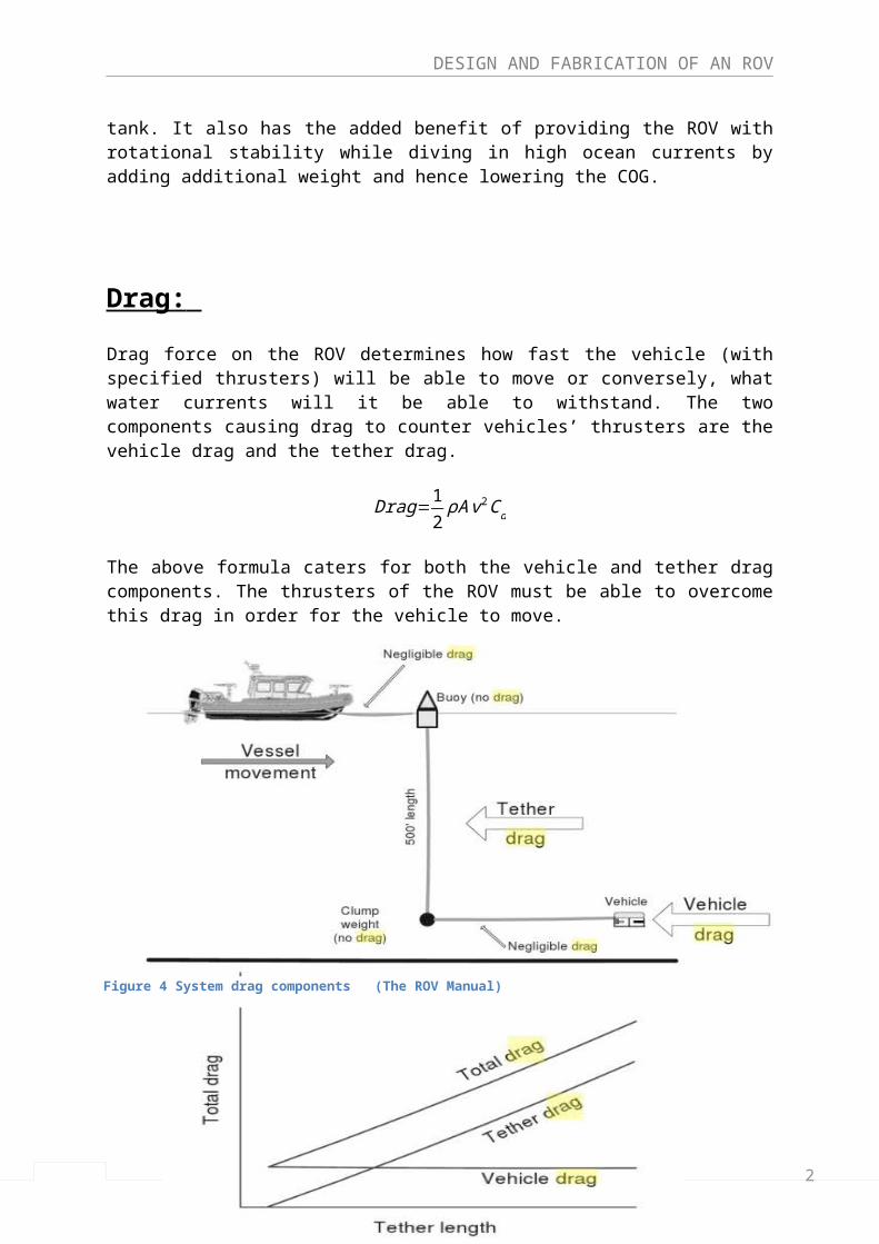
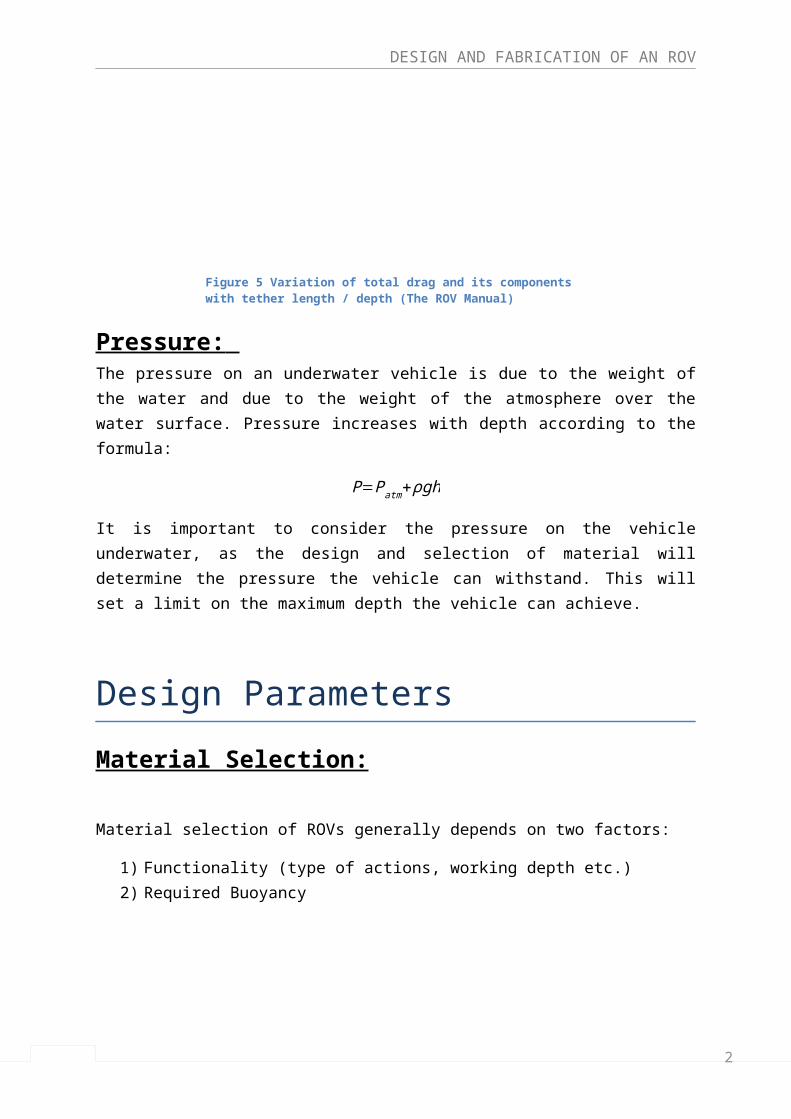
Drag force on the ROV determines how fast the vehicle (with specified thrusters) will be able to move or conversely, what water currents will it be able to withstand. The two components causing drag to counter vehicles’ thrusters are the vehicle drag and the tether drag.
Drag=12ρA v2Cd
The above formula caters for both the vehicle and tether drag components. The thrusters of the ROV must be able to overcome this drag in order for the vehicle to move.
Figure 4 System drag components (The ROV Manual)
Figure 5 Variation of total drag and its components with tether length / depth (The ROV Manual)
2
DESIGN AND FABRICATION OF AN ROV
Pressure: The pressure on an underwater vehicle is due to the weight of the water and due to the weight of the atmosphere over the water surface. Pressure increases with depth according to the formula:
P=Patm+ρgh
It is important to consider the pressure on the vehicle underwater, as the design and selection of material will determine the pressure the vehicle can withstand. This will set a limit on the maximum depth the vehicle can achieve.
Design Parameters
Material Selection:
Material selection of ROVs generally depends on two factors:
1) Functionality (type of actions, working depth etc.)2) Required Buoyancy
Although many materials are being used to construct ROVs, the choice was narrowed down to four, depending on our requirements:
1) Polyvinyl Chloride (PVC)2) Polypropylene (PP)3) Fiberglass4) Aluminum
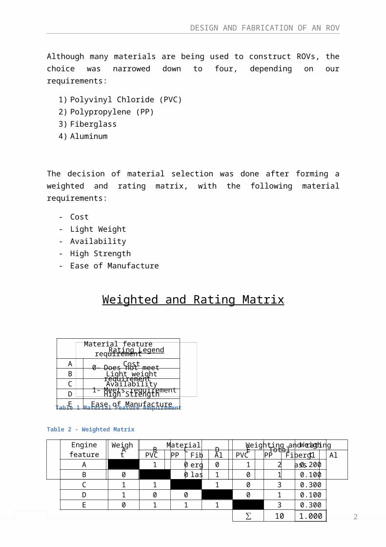
The decision of material selection was done after forming a weighted and rating matrix, with the following material requirements:
- Cost- Light Weight- Availability- High Strength- Ease of Manufacture
2
DESIGN AND FABRICATION OF AN ROV
Weighted and Rating Matrix
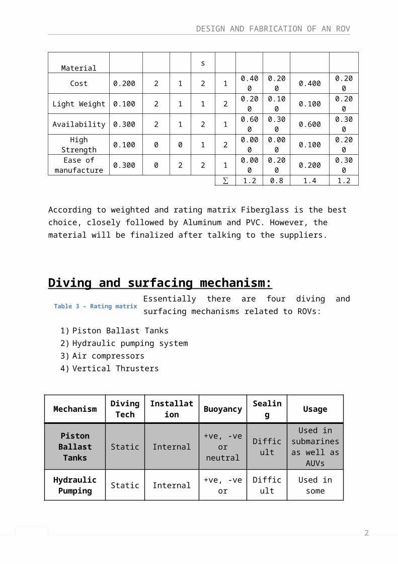
Table 2 - Weighted Matrix
Material feature
Weight
Material Weighting and rating
PVC PPFiberglas
sAl PVC PP
Fiberglass
Al
Cost 0.200 2 1 2 1 0.400 0.200 0.400 0.200Light Weight 0.100 2 1 1 2 0.200 0.100 0.100 0.200Availability 0.300 2 1 2 1 0.600 0.300 0.600 0.300
High Strength 0.100 0 0 1 2 0.000 0.000 0.100 0.200Ease of
manufacture0.300 0 2 2 1 0.000 0.200 0.200 0.300
∑ 1.2 0.8 1.4 1.2
According to weighted and rating matrix Fiberglass is the best choice, closely followed by Aluminum and PVC. However, the material will be finalized after talking to the suppliers.
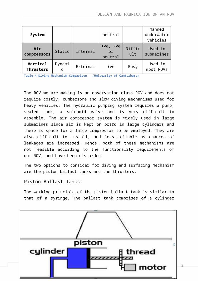
Diving and surfacing mechanism:Essentially there are four diving and surfacing mechanisms related to ROVs:
1) Piston Ballast Tanks2) Hydraulic pumping system
3) Air compressors
Rating Legend
0- Does not meet requirement1- Meets requirement partially2- Meets requirement fully
Table 1 Material Feature Requirement
Table 3 – Rating matrix
Material feature requirementA CostB Light weightC AvailabilityD High StrengthE Ease of Manufacture
Engine feature
A B C D E Total Weight
A 1 0 0 1 2 0.200B 0 0 1 0 1 0.100C 1 1 1 0 3 0.300D 1 0 0 0 1 0.100E 0 1 1 1 3 0.300
∑ 10 1.000
2
DESIGN AND FABRICATION OF AN ROV
4) Vertical Thrusters
MechanismDiving Tech
Installation Buoyancy Sealing Usage
Piston Ballast Tanks
Static Internal+ve, -ve or
neutralDifficult
Used in submarines as well as
AUVs
Hydraulic Pumping System
Static Internal+ve, -ve or
neutralDifficult
Used in some
manned underwater
vehicles
Air compressors
Static Internal+ve, -ve or
neutralDifficult
Used in submarines
Vertical Thrusters
Dynamic External +ve EasyUsed in most
ROVs
Table 4 Diving Mechanism Comparison (University of Canterbury)
The ROV we are making is an observation class ROV and does not require costly, cumbersome and slow diving mechanisms used for heavy vehicles. The hydraulic pumping system requires a pump, sealed tank, a solenoid valve and is very difficult to assemble. The air compressor system is widely used in large submarines since air is kept on board in large cylinders and there is space for a large compressor to be employed. They are also difficult to install, and less reliable as chances of leakages are increased. Hence, both of these mechanisms are not feasible according to the functionality requirements of our ROV, and have been discarded.
The two options to consider for diving and surfacing mechanism are the piston ballast tanks and the thrusters.
Piston Ballast Tanks:
2
DESIGN AND FABRICATION OF AN ROV
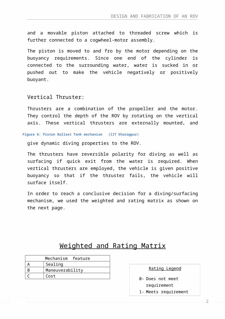
The working principle of the piston ballast tank is similar to that of a syringe. The ballast tank comprises of a cylinder and a movable piston attached to threaded screw which is further connected to a cogwheel-motor assembly.
The piston is moved to and fro by the motor depending on the buoyancy requirements. Since one end of the cylinder is connected to the surrounding water, water is sucked in or pushed out to make the vehicle negatively or positively buoyant.
Vertical Thruster:
Thrusters are a combination of the propeller and the motor. They control the depth of the ROV by rotating on the vertical axis. These vertical thrusters are externally mounted, and give dynamic diving properties to the ROV.
The thrusters have reversible polarity for diving as well as surfacing if quick exit from the water is required. When vertical thrusters are employed, the vehicle is given positive buoyancy so that if the thruster fails, the vehicle will surface itself.
In order to reach a conclusive decision for a diving/surfacing mechanism, we used the weighted and rating matrix as shown on the next page.
Weighted and Rating Matrix
Figure 6: Piston Ballast Tank mechanism (IIT Kharagpur)
2
DESIGN AND FABRICATION OF AN ROV
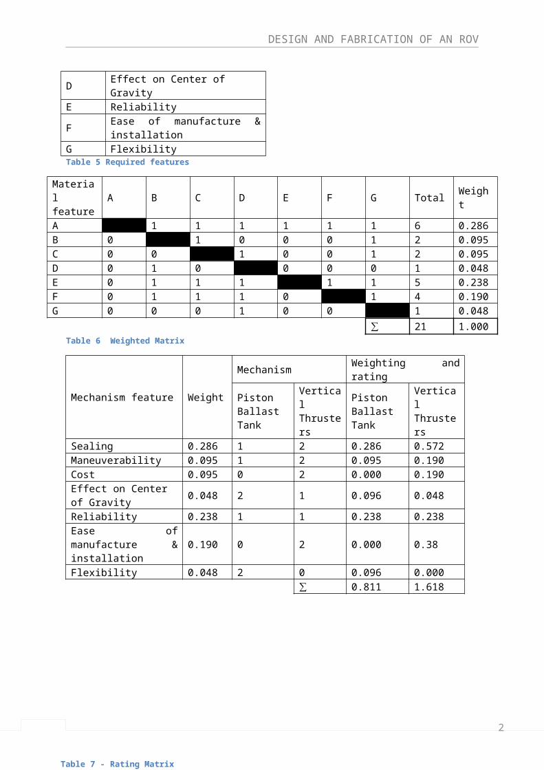
Mechanism featureA SealingB ManeuverabilityC CostD Effect on Center of GravityE Reliability
FEase of manufacture & installation
G FlexibilityTable 5 Required features
Material feature
A B C D E F G Total Weight
A 1 1 1 1 1 1 6 0.286B 0 1 0 0 0 1 2 0.095C 0 0 1 0 0 1 2 0.095D 0 1 0 0 0 0 1 0.048E 0 1 1 1 1 1 5 0.238F 0 1 1 1 0 1 4 0.190
G 0 0 0 1 0 0 1 0.048
∑ 21 1.000Table 6 Weighted Matrix
Mechanism feature Weight
Mechanism Weighting and ratingPiston Ballast Tank
Vertical Thrusters
Piston Ballast Tank
Vertical Thrusters
Sealing 0.286 1 2 0.286 0.572
Maneuverability 0.095 1 2 0.095 0.190
Cost 0.095 0 2 0.000 0.190Effect on Center of Gravity
0.048 2 1 0.096 0.048
Reliability 0.238 1 1 0.238 0.238Ease of manufacture & installation
0.190 0 2 0.000 0.38
Flexibility 0.048 2 0 0.096 0.000
∑ 0.811 1.618
As per the result of the weighted and rating matrix, vertical thrusters are a far better choice, and will be used for our ROV.
Propulsion Mechanism:
Rating Legend
0- Does not meet requirement1- Meets requirement partially2- Meets requirement fully
Table 7 - Rating Matrix
2
DESIGN AND FABRICATION OF AN ROV
Propulsion mechanism in ROVs is either electro-hydraulic or electric. However, due to the weight and lower efficiency, electro-hydraulic mechanism is not considered.
We will be using a direct drive electric propulsion system that uses a separate electric motor for each propeller.
The actual amount of thrust required for movement is a function of the drag on the vehicle and the available power. Power absorbed at a specified velocity is given by:
Power=drag×v550
Thruster positioning:
Thruster positioning determines the maneuverability and controllability of the ROV. The moment arm of the thruster relative to the center of mass will be adjusted to allow varying degrees of maneuverability.
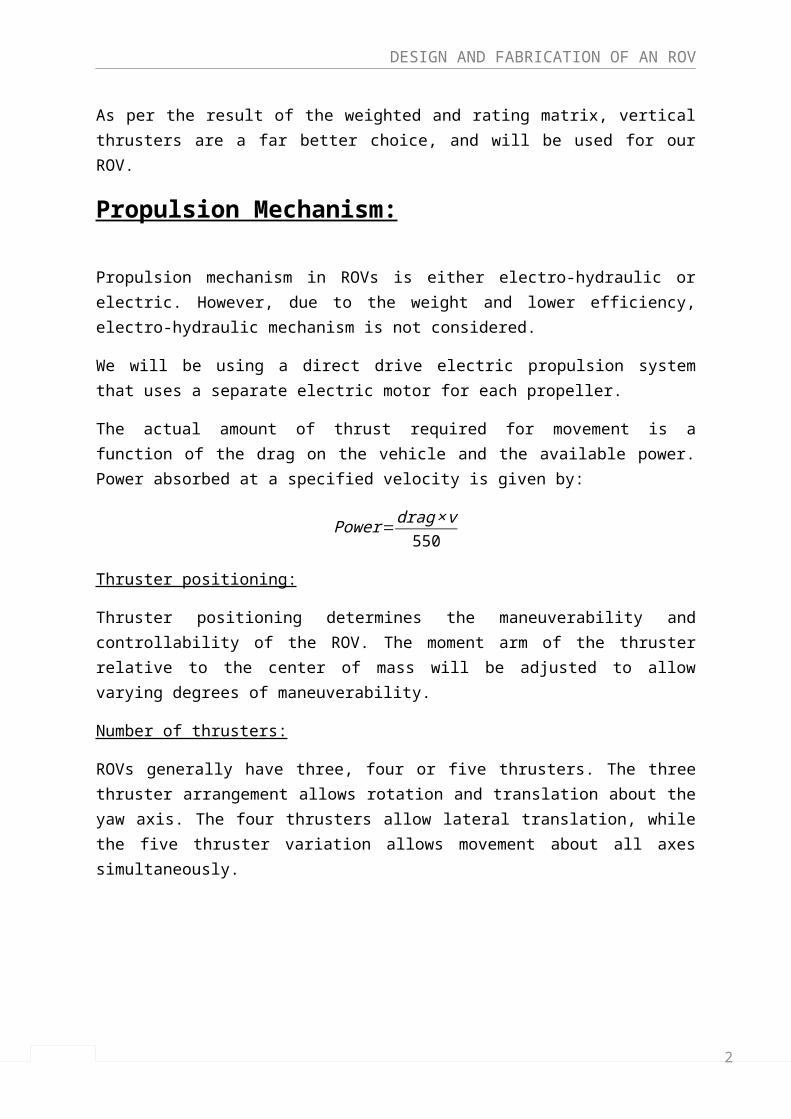
Number of thrusters:
ROVs generally have three, four or five thrusters. The three thruster arrangement allows rotation and translation about the yaw axis. The four thrusters allow lateral translation, while the five thruster variation allows movement about all axes simultaneously.
Figure 7 Different thruster arrangements (the ROV manual)
The observation class ROV does not require lateral maneuverability or the ability to rotate on its footprint. According to our requirement we will be selecting a three thruster version of the ROV, however a vertical thruster may be added to add additional diving thrust.
Two important components of the propulsion mechanism:
Motor
2
DESIGN AND FABRICATION OF AN ROV
We can either use a constant speed DC motor, stepper motor or an innovative solution of using bilge pumps.
The problem with using a normal DC motor for an ROV is that it is not sealed or ready to use underwater. It requires a waxing process to make it water proof. This stiffens the rotation shaft of the motor, and slows down the motor while producing more friction. Thus, the efficiency of the thrusting mechanism is reduced.
Since buying a factory made water proof motor is expensive, a cheaper and simpler solution is to use the motors used in bilge pumps. These pumps are normally used to remove water from the inside of a boat. They are meant to be submerged, built to be waterproof and are fairly powerful and easy to add to an existing ROV.
This idea was used by teams competing in Marine Advanced Technology competitions, and we aim to test this idea on our ROV.
Propeller
A continuous pitch propeller will be used and its diameter, pitch and width will depend on the current draw and the thrust combination of the motor and the propeller. The standard size of the propeller for a small ROV is 60mm. However, the best combination of propeller and motor will be achieved through an experimentation process measuring current draw and thrust produced, by means of a simple bollard pull test.
The propeller will be enclosed in a housing around its circumference. This provides safety for the operator, and increases reliability as the propeller is protected from damage in case of contact with any other structure.
Control Systems
2
DESIGN AND FABRICATION OF AN ROV
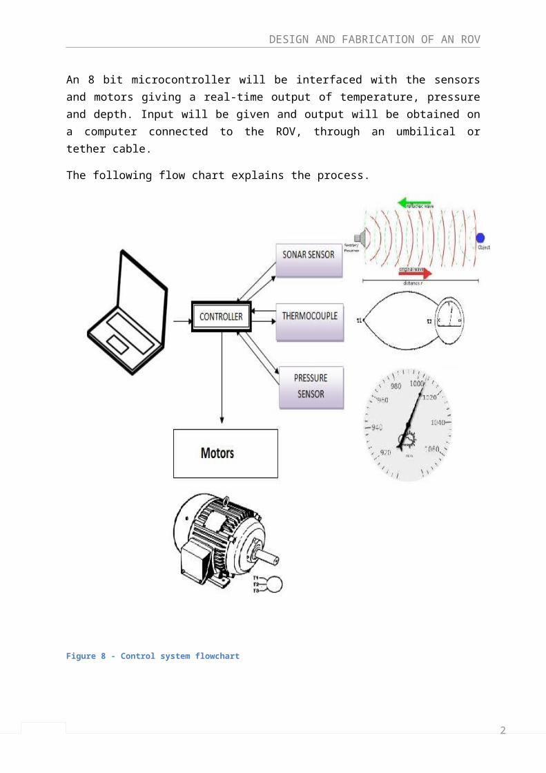
An 8 bit microcontroller will be interfaced with the sensors and motors giving a real-time output of temperature, pressure and depth. Input will be given and output will be obtained on a computer connected to the ROV, through an umbilical or tether cable.
The following flow chart explains the process.
Figure 8 - Control system flowchart
2
DESIGN AND FABRICATION OF AN ROV
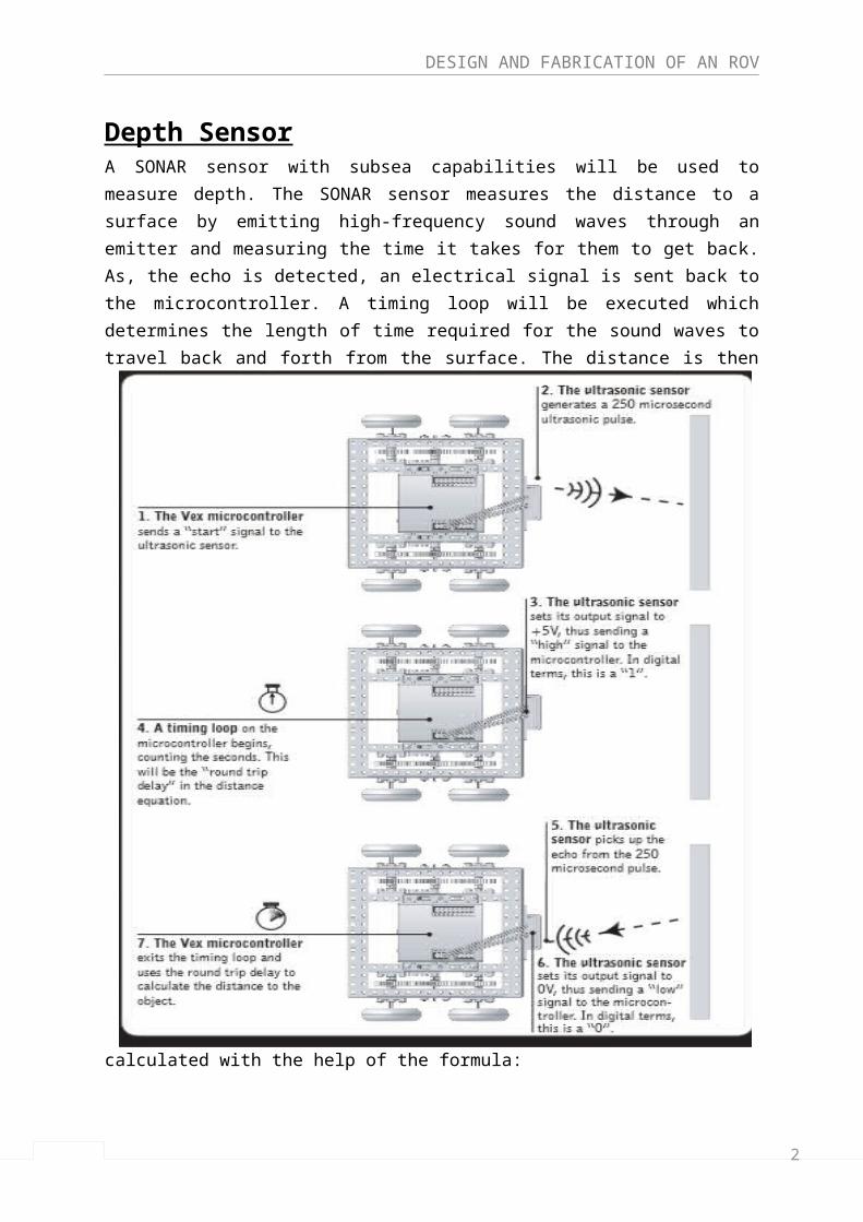
Depth SensorA SONAR sensor with subsea capabilities will be used to measure depth. The SONAR sensor measures the distance to a surface by emitting high-frequency sound waves through an emitter and measuring the time it takes for them to get back. As, the echo is detected, an electrical signal is sent back to the microcontroller. A timing loop will be executed which determines the length of time required for the sound waves to travel back and forth from the surface. The distance is then calculated with the help of the formula:
Distance to object = ½ (speed of sound) x (time taken)
Figure 9 Sensor interfaced with the microcontroller (Carnegie Mellon Robotics Academy)
2
DESIGN AND FABRICATION OF AN ROV
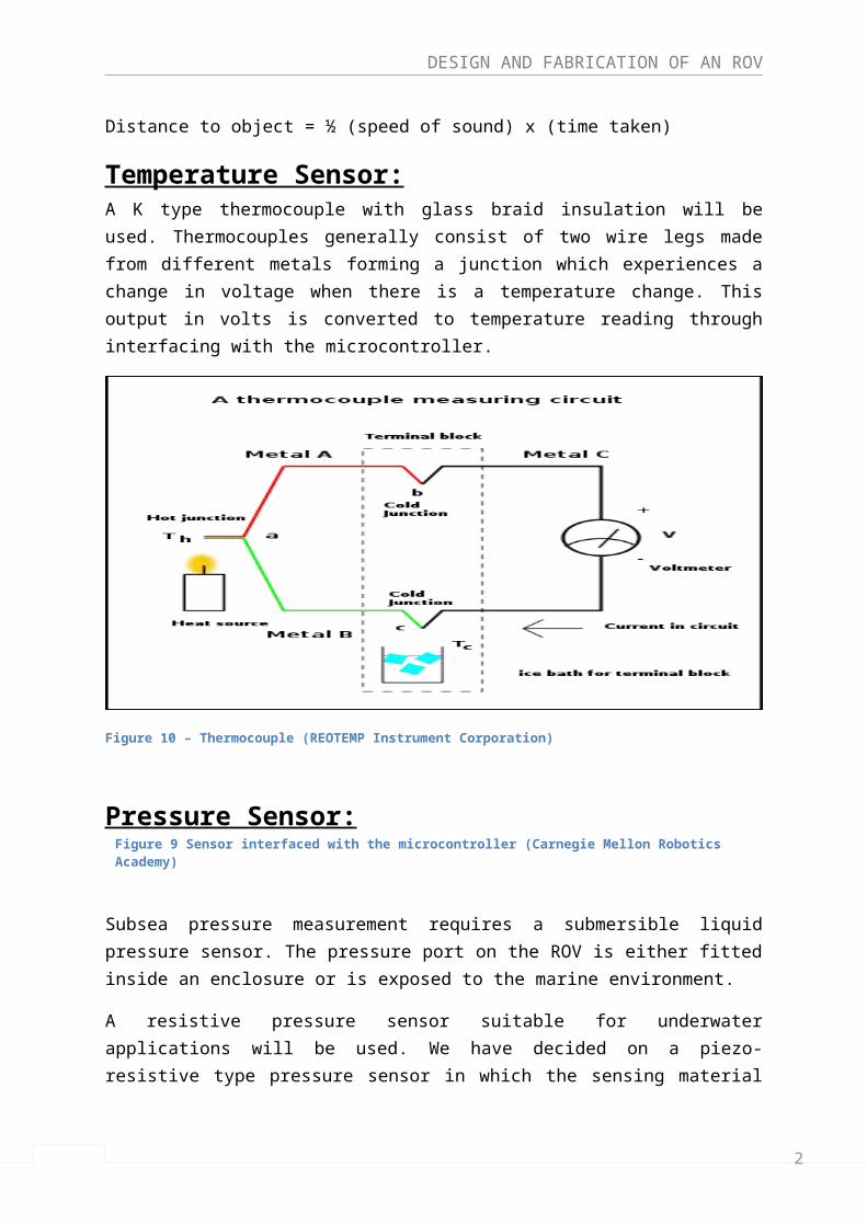
Temperature Sensor:A K type thermocouple with glass braid insulation will be used. Thermocouples generally consist of two wire legs made from different metals forming a junction which experiences a change in voltage when there is a temperature change. This output in volts is converted to temperature reading through interfacing with the microcontroller.
Figure 10 – Thermocouple (REOTEMP Instrument Corporation)
Pressure Sensor:Subsea pressure measurement requires a submersible liquid pressure sensor. The pressure port on the ROV is either fitted inside an enclosure or is exposed to the marine environment.
A resistive pressure sensor suitable for underwater applications will be used. We have decided on a piezo-resistive type pressure sensor in which the sensing material is a diaphragm formed on a silicon substrate, which bends with applied pressure and leads to a change of resistivity of the material. As the depth of the dive increases, pressure is exerted on the diaphragm of the sensor. A correlation between the change in resistivity and pressure is used through interfacing with the microcontroller.
2
DESIGN AND FABRICATION OF AN ROV
Design Specifications
ROV Class:
Class II A (Observation class with payload option).
Our ROV falls into this class, since our aim is to build an ROV with a capability of carrying sensors to gather data. However, the use of a video camera will depend on availability of funds.
Function:
Ability to sense and provide real time data such as temperature, pressure and depth of the aquatic environment.
Mobility:
- Diving up to a minimum depth of 10 meters.- Rotational/turning circle of 360 o about the yaw axis, will allow the vehicle to
maneuver in any direction.- Ranging distance of 10 meters.
Buoyancy:
The vehicle will be constructed to be positively buoyant (close to neutral).
The reasons for this decision are:
- The vehicle returns to the surface in case of power/equipment failure.- Allows near bottom maneuvering without thrusting upwards and disturbing the
surface.- Eliminates the need for continuous thrust reversal, thus saving power.
Ballast tanks:
- Type: Fixed air ballast tank.- Orientation: Will be installed on top of the ROV along its longitudinal axis.
Weighted skids:
- Two weighted skids will be installed at the bottom of the ROV. They allow us to vary the buoyancy by adding or removing weights.
2
DESIGN AND FABRICATION OF AN ROV
Stability:
As mentioned before, the stability criterion for an ROV is to have a considerable distance between the COB and COG. However, if the distance is too large the maneuverability of the ROV is compromised.
By calculated positioning of the ballast tanks and weighted skids, we can raise or lower the COB and COG, respectively. A compromise between maneuverability and stability must be reached through calculation and experimentation.
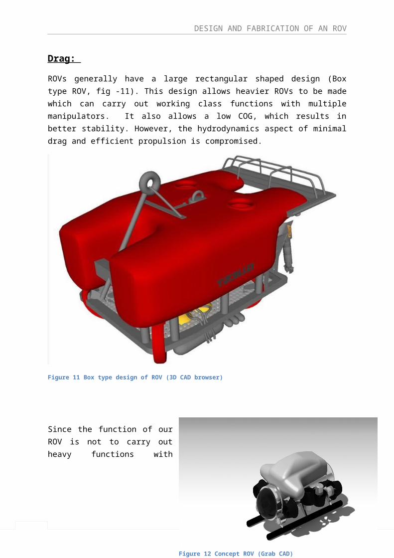
Drag:
ROVs generally have a large rectangular shaped design (Box type ROV, fig -11). This design allows heavier ROVs to be made which can carry out working class functions with multiple manipulators. It also allows a low COG, which results in better stability. However, the hydrodynamics aspect of minimal drag and efficient propulsion is compromised.
Figure 11 Box type design of ROV (3D CAD browser)
2
DESIGN AND FABRICATION OF AN ROV
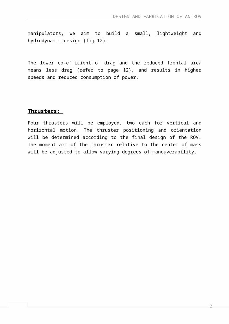
Since the function of our ROV is not to carry out heavy functions with manipulators, we aim to build a small, lightweight and hydrodynamic design (fig 12).
The lower co-efficient of drag and the reduced frontal area means less drag (refer to page 12), and results in higher speeds and reduced consumption of power.
Thrusters:
Four thrusters will be employed, two each for vertical and horizontal motion. The thruster positioning and orientation will be determined according to the final design of the ROV. The moment arm of the thruster relative to the center of mass will be adjusted to allow varying degrees of maneuverability.
Figure 12 Concept ROV (Grab CAD)
2
DESIGN AND FABRICATION OF AN ROV
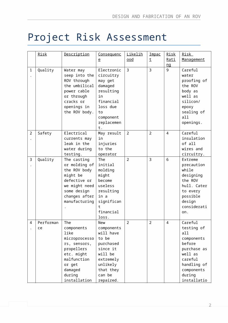
Project Risk AssessmentRisk Description Consequence Likelihood Impact Risk
RatingRisk Management
1. Quality Water may seep into the ROV through the umbilical power cable or through cracks or openings in the ROV body.
Electronic circuitry may get damaged resulting in financial loss due to component replacement.
3 3 9 Careful water proofing of the ROV body as well as silicon/ epoxy sealing of all openings.
2. Safety Electrical currents may leak in the water during testing.
May result in injuries to the operator
2 2 4 Careful insulation of all wires and circuitry.
3. Quality The casting or molding of the ROV body might be defective or we might need some design changes after manufacturing.
The initial molding might become useless resulting in a significant financial loss.
2 3 6 Extreme precaution while designing the ROV hull. Cater to every possible design consideration.
4. Performance The components like microprocessors, sensors, propellers etc. might malfunction or get damaged during installation or testing.
New components will have to be purchased since it will be extremely unlikely that they can be repaired. Will result in financial loss.
2 2 4 Careful testing of all components before purchase as well as careful handling of components during installation and testing.
5. Cost The fabrication of ROV body as well as cost of components might be significantly higher than we have originally estimated.
Severe setback in the project as It might affect the functionality of the project.
2 3 6 Obtain complete market knowledge of the cost of all components as well as manufacturing cost.
Risk Statement:
Table 8 Risk Assessment
2
DESIGN AND FABRICATION OF AN ROV
We have to be especially mindful of the risks having a higher rating on the chart, since they are more likely to severely affect the project. They might cause delays, reduction of quality and even incomplete termination of the project.
Quality risk pertaining to seepage of water inside the ROV body has the highest risk rating of 9. This means that a proper waxing and sealing process must be ensured, and the vehicle must be tested for leakages before installation of components. Both, the cost and quality risk regarding defective manufacturing have a comparatively high rating of 6. They must be next on our priority list while managing the risks. Proper market survey, selection of supplier and monitoring of the manufacturing process should be ensured.
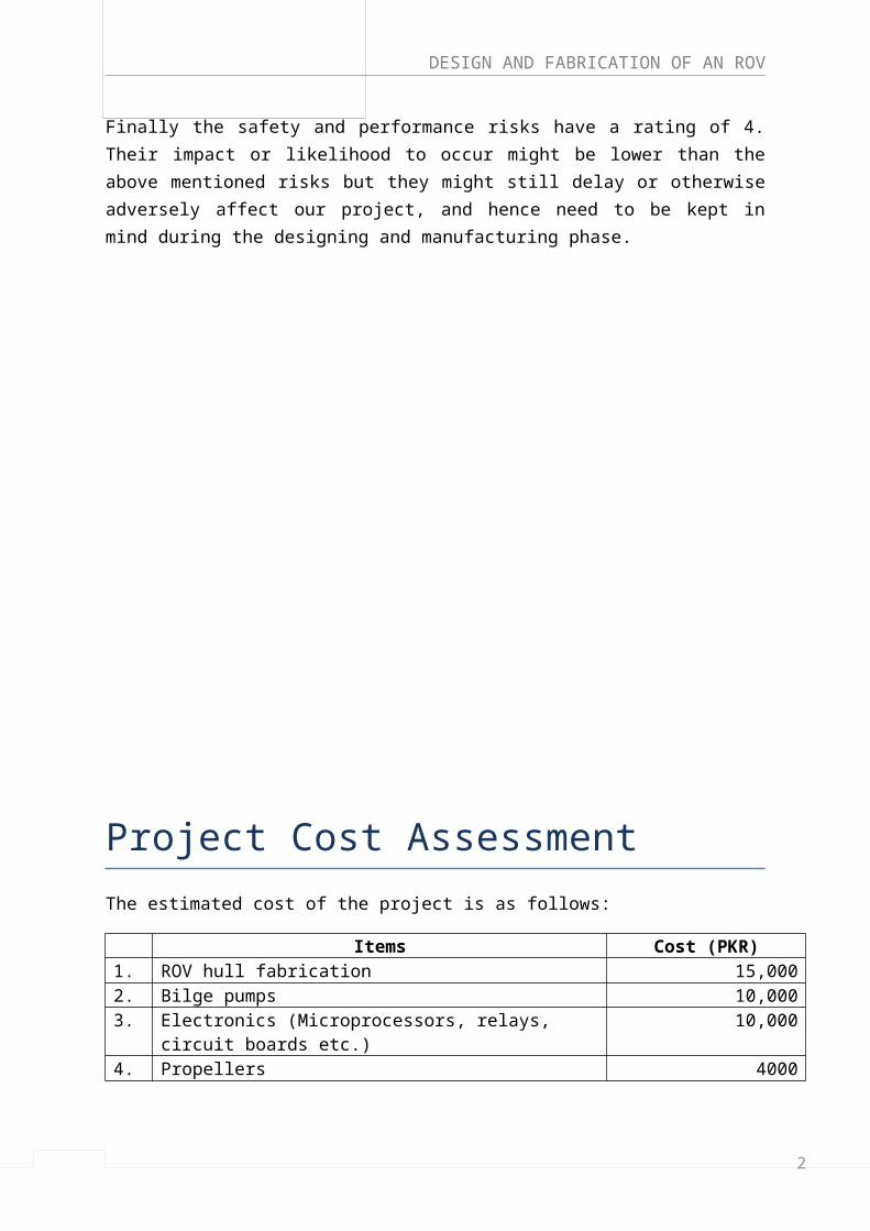
Finally the safety and performance risks have a rating of 4. Their impact or likelihood to occur might be lower than the above mentioned risks but they might still delay or otherwise adversely affect our project, and hence need to be kept in mind during the designing and manufacturing phase.
Project Cost Assessment
2
DESIGN AND FABRICATION OF AN ROV
The estimated cost of the project is as follows:
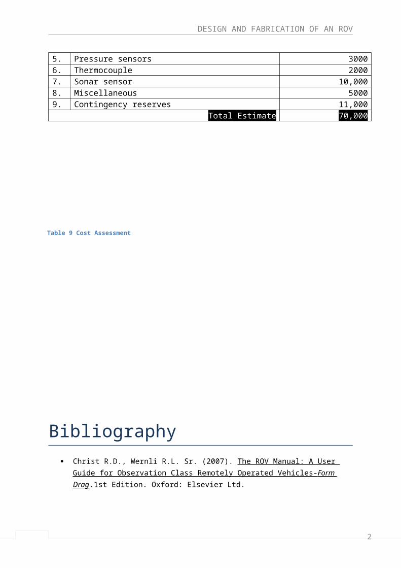
Items Cost (PKR)1. ROV hull fabrication 15,0002. Bilge pumps 10,0003. Electronics (Microprocessors, relays, circuit boards etc.) 10,0004. Propellers 40005. Pressure sensors 30006. Thermocouple 20007. Sonar sensor 10,0008. Miscellaneous 50009. Contingency reserves 11,000
Total Estimate 70,000
Bibliography
Table 9 Cost Assessment
2
DESIGN AND FABRICATION OF AN ROV
Christ R.D., Wernli R.L. Sr. (2007). The ROV Manual: A User Guide for Observation Class Remotely Operated Vehicles- Form Drag .1st Edition. Oxford: Elsevier Ltd.
Steve (1998). How to’s and FAQ’s [Online]. Homebuilt ROV’s. Available from: <http://www.homebuiltrovs.com/howtos.html>. [Accessed 5th April 2013]
MATE. Underwater Robotics competition [Online]. Available from:<http://www.marinetech.org/rov-competition-2/>. [Accessed 5th April 2013]
Marine Technology Society. What is an ROV? [Online]. Available from: <http://www.rov.org/rov_overview.cfm>. [Accessed 8thApril 2013]
Marine Technology Society. ROV- A brief History [Online]. Available from: <http://www.rov.org/rov_history.cfm>. [Accessed 8thApril 2013]
Marine Technology Society. ROV applications- Design Overview [Online]. Available from: <http://www.rov.org/rov_design_overview.cfm>. [Accessed 8thApril 2013]
Marine Technology Society. ROV applications- Design – Ballast, Buoyancy Control [Online]. Available from: <http://www.rov.org/rov_design_ballast.cfm>. [Accessed 8thApril 2013]
Marine Technology Society. ROV applications- Design – Drag [Online]. Available from: <http://www.rov.org/rov_design_drag.cfm>. [Accessed 8thApril 2013]
Marine Technology Society. ROV applications- Design – Propulsion [Online]. Available from: <http://www.rov.org/rov_design_propulsion.cfm>. [Accessed 8thApril 2013]
ROV World. FAQ’s about ROV’s [Online]. Available from: <http://www.rovworld.com/faq-8-About+ROV.html>. [Accessed 8th April 2013]
American Sensor Technologies. Sub-Sea level Measurement with pressure sensors [Online]. Available from <http://www.astsensors.com/application/pressure/sub-sea-pressure-sensors.php>. [Accessed 10th April 2013]
Carnegie Mellon Robotics Academy. Ultrasonic Sensor Kit [online]. Pittsburgh: Carnegie Mellon University. Available from: <http://www.education.rec.ri.cmu.edu/products/teaching_robotc_cortex/reference/ultrasonic_ig.pdf>. [Accessed 10th April 2013]
Eastern Robotics (2010). ROV Program [Online]. Available from: <http://www.marinetech.org/files/marine/files/MIROV2MANUAL.pdf>. [Accessed 11th April 2013]
Martos G., Abreu A., Gonzalez S. (2013). Remotely Operated Underwater Vehicle: 25% Report. Florida International University, Florida. Institute Research Report. Available from: <http://www.mme.fiu.edu/wpcontent/uploads/2013/04/T1_AquaBot.pdf>. [Accessed 13th April 2013]
William John West (2009). Remotely Operated Underwater Vehicle [Online]. Newnham, Tasmania: Australian Maritime College. Research Report. Available from: <https://elibrary.utas.edu.au/utas/file/72fadf8e-fe6f-79f8-8b1d-83e6e8a5b393/1/West%20ch1.pdf>. [Accessed 18th April 2013]
2
DESIGN AND FABRICATION OF AN ROV
IIT-Kanpur- Fluid Mechanics Lecture. Stability of Unconstrained Submerged Bodies in Fluid [Online]. Kanpur: IIT Web-course. Available from: < http://nptel.iitm.ac.in/courses/Webcourse-contents/IIT-KANPUR/FLUID-MECHANICS/lecture-5/5-6_stability_submerged_fluid.htm >. [Accessed 15th April 2013]
Tecnadyne. WHAT SIZE THRUSTERS DO I NEED FOR MY ROV OR AUV? [Online]. Available from: < http://tecnadyne.wordpress.com/2012/04/28/what-size-thrusters-do-i-need-for-my-rov-or-auv-7-2/ >. [Accessed 15th April 2013]
Standards Norway (2012). Remotely Operated Vehicle (ROV) Classification [Online] 2nd Edition. Lysake, Norway: Standards Norway. Available From: < http://www.standard.no/PageFiles/23559/u102u2.pdf >. [Accessed 16th April 2013]
W.H. Wang, R.C. Engelaar, X.Q. Chen & J.G. Chase. The State-of-Art of Underwater Vehicles – Theories and Applications. New Zealand: University of Canterbury, Netherlands: University of Technology Eindhoven. Available from:< http://ir.canterbury.ac.nz/bitstream/10092/4130/1/12612285_State-of-Art%20of%20Underwater%20Vehicles.pdf >. [Accessed 14th April 2013]
ROBOTIX Technology Society (2013). Submarine Dive Technology. Indian Institute of Technology, Kharagpur. Available from: < http://robotix.in/tutorials/category/mechanical/submarinetut >. [Accessed 10th April 2013]
Appendix - A
2
DESIGN AND FABRICATION OF AN ROV
GANNT CHART
2
DESIGN AND FABRICATION OF AN ROV
2
DESIGN AND FABRICATION OF AN ROV
Appendix - B
Statement of Requirement
Title Design and fabrication of a Remotely Operated Underwater Vehicle
Issue: 01 Date: 14-03-2013
CHANGES D/W REF REQUIREMENTS
1 Introduction
1.1 Preamble
Marine mapping has become an important concern for many industries such as Oil & Gas and Military. The availability of oceanic data is the cornerstone of most oceanographic studies. Even today a majority of our ocean floors remain unmapped because the cost and hazards of sending manned underwater missions to gather oceanic data far outweigh its benefits.
By creating a prototype Remotely Operated Underwater vehicle capable of providing oceanic data, we aim to test an innovative concept which significantly reduces the cost and hazards that have previously been associated with marine mapping.
1.2 Scope
1.2.1 The scope of this project is to design and fabricate a prototype ROV that can be used to gather and compile oceanic data.
1.3 Related Documents
1.3.1 Books
1.3.1.1 Introduction to Naval Architecture
By Thomas C. Gillmer and Bruce Johnson
1.3.1.2 Naval Architecture for Marine Engineers
By W. Muckle
2
DESIGN AND FABRICATION OF AN ROV
1.3.1.3 Submarine Technology for the 21st century
By Stan Zimmerman
1.3.1.4 Reed’s Instrumentation and control systems
By Leslie Jackson
1.3.1.5 Design with microcontrollers
By John B. Peatman
1.3.2 Software
1.3.2.1 SolidWorks / Solid Edge
1.3.2.2 ANSYS
1.3.2.3 LabVIEW
1.3.2.4 C, C++ and Assembly language
1.4 Symbols
From the D/W column of this table
D Demand A mandatory requirement
W(H) Wish high A highly desirable attribute
W(L) Wish low A low desirable attribute
1.5 Deliverables
W(H) The ROV should be able to record and transmit oceanic data accurately along with perfect manoeuvrability in six directions.
W(L) Installation of sensors and data logging device for underwater mapping.
D 3D software model of the underwater-vehicle
D Design, analysis, selection and fabrication of a diving and surfacing mechanism.
D Design and fabrication of a watertight outer body.
2
DESIGN AND FABRICATION OF AN ROV
D Assembly of parts to produce a stable and hydrodynamically efficient vehicle.
D Final Project Report.
2 Technical Requirements
2.1.1 Stepper motors, Solenoid Valves, Microcontrollers, Sensors, Propellers and circuit board.
2.1.2 Knowledge of the above mentioned softwares
2.1.3 Knowledge of Naval Architecture, Fluid Mechanics, Material Sciences, Control Systems, Instrumentation, Robotics and Computer Programming
2.2 Design Considerations
2.2.1 Material Selection
2.2.2 Buoyancy control mechanism
2.2.3 Manoeuvrability control mechanism
2.2.4 Availability of components
2.2.5 Cost considerations
3 Miscellaneous
3.1 Training for Solidworks, LabVIEW and programming languages.
4 Hazards/Safety
4.1 One of the team member should know how to swim, in case the ROV malfunctions.
4.2 Water may seep into the circuitry inside if not properly sealed.
4.3 All wires should be checked for proper insulation, before immersing in water.
2
DESIGN AND FABRICATION OF AN ROV
5 Costs
5.1 The estimated cost of the Project is approx.
Rs. 70,000.
5.2 The above mentioned cost is subjected to material cost, assembly requirements, and testing.
Project Advisor's
Signature