Embed Size (px)
Citation preview

CDN067DEVICENET
SPECIFICATIONS

CDN067 DEVICE
Revision 1.3 08/04/97 i
Revision History
Revision Description Date1.0 Initial Release
Upgrade to DNet Rev. 2.0 07/20/98Added support for status byte and status clear in pollDisallowed changing of items that affect produce consume sizewhen poll connection has been established
1.1 Update hardware connection information 11/17/98
TABLE OF CONTENTS

CDN067 DEVICE
Revision 1.3 08/04/97 ii
REVISION HISTORY ................................................................................................................................................ I
OVERVIEW.................................................................................................................................................................1
HARDWARE INTERFACE.......................................................................................................................................1
DEVICENET MICRO CONNECTOR ......................................................................................................................................1DB-9 RS485 CONNECTIONS .............................................................................................................................................2DB-9 RS422 CONNECTIONS .............................................................................................................................................2MACID SWITCH.................................................................................................................................................................2DATA RATE SWITCH ..........................................................................................................................................................3DEVICENET INDICATOR LED’S .........................................................................................................................................3RS485/422 ACTIVITY LED’S ............................................................................................................................................3OPTION SWITCH .................................................................................................................................................................3SPECIFICATIONS .................................................................................................................................................................3
DeviceNet Interface..............................................................................................................................................4RS485/422 ............................................................................................................................................................4Environmental......................................................................................................................................................4
DEVICENET INFORMATION .................................................................................................................................5
DEVICENET MESSAGE TYPES............................................................................................................................................6DEVICENET CLASS SERVICES............................................................................................................................................6DEVICENET OBJECT CLASSES ...........................................................................................................................................7
IDENTITY OBJECT...................................................................................................................................................8
IDENTITY OBJECT CLASS ATTRIBUTES ..............................................................................................................................8IDENTITY OBJECT, INSTANCE 1 ATTRIBUTES....................................................................................................................8IDENTITY OBJECT COMMON SERVICES .............................................................................................................................8
ROUTER OBJECT ...................................................................................................................................................10
ROUTER OBJECT CLASS ATTRIBUTES..............................................................................................................................10ROUTER OBJECT, INSTANCE 1 ATTRIBUTES....................................................................................................................10ROUTER OBJECT COMMON SERVICES .............................................................................................................................10
DEVICENET OBJECT.............................................................................................................................................11
DEVICENET OBJECT CLASS ATTRIBUTES........................................................................................................................11DEVICENET OBJECT, INSTANCE 1 ATTRIBUTES..............................................................................................................11DEVICENET OBJECT COMMON SERVICES .......................................................................................................................11ATTRIBUTE 1 – MACID ...................................................................................................................................................11ATTRIBUTE 2 – BAUD RATE ............................................................................................................................................12ATTRIBUTE 3 – BUS OFF INTERRUPT ..............................................................................................................................12ATTRIBUTE 4 – BUS OFF COUNTER.................................................................................................................................12ATTRIBUTE 5 – ALLOCATION BYTE.................................................................................................................................12
ASSEMBLY OBJECT ..............................................................................................................................................13
ASSEMBLY OBJECT CLASS ATTRIBUTES .........................................................................................................................13ASSEMBLY OBJECT, INSTANCE 1 ATTRIBUTES ...............................................................................................................13ASSEMBLY OBJECT, INSTANCE 2 ATTRIBUTES ...............................................................................................................13ASSEMBLY OBJECT COMMON SERVICES.........................................................................................................................13

CDN067 DEVICE
Revision 1.3 08/04/97 iii
ATTRIBUTE 1 – INPUT DATA ...........................................................................................................................................13ATTRIBUTE 2 – OUTPUT DATA........................................................................................................................................13
CONNECTION OBJECT.........................................................................................................................................14
CONNECTION OBJECT CLASS ATTRIBUTES......................................................................................................................14CONNECTION OBJECT, INSTANCE 1 ATTRIBUTES (EXPLICIT MESSAGE).........................................................................14CONNECTION OBJECT, INSTANCE 2 ATTRIBUTES (POLL CONNECTION)........................................................................14CONNECTION CLASS COMMON SERVICES .......................................................................................................................15
SERIAL STREAM OBJECT....................................................................................................................................17
SERIAL STREAM CLASS ATTRIBUTES ..............................................................................................................................17SERIAL STREAM OBJECT, INSTANCE 1 ATTRIBUTES .......................................................................................................17SERIAL STREAM COMMON SERVICES..............................................................................................................................18ATTRIBUTE 3 – RECEIVED DATA.....................................................................................................................................18ATTRIBUTE 4 – TRANSMITTED DATA..............................................................................................................................18ATTRIBUTE 4 – STATUS ATTRIBUTE................................................................................................................................18ATTRIBUTE 6 – BAUD RATE ............................................................................................................................................19ATTRIBUTE 7 – PARITY ...................................................................................................................................................19ATTRIBUTE 8 – DATA SIZE ..............................................................................................................................................20ATTRIBUTE 9 – STOP BITS ...............................................................................................................................................20ATTRIBUTE 10 – FLOW CONTROL ...................................................................................................................................20ATTRIBUTE 11 – RECEIVE COUNT...................................................................................................................................20ATTRIBUTE 12 – TRANSMIT COUNT................................................................................................................................20ATTRIBUTE 13 – MAXIMUM RECEIVE SIZE .....................................................................................................................21ATTRIBUTE 14 – DATA FORMAT .....................................................................................................................................21ATTRRIBUTE 15 – BLOCK MODE.....................................................................................................................................22ATTRIBUTE 16 - DELIMITER ............................................................................................................................................26ATTRIBUTE 17 – PAD CHARACTER..................................................................................................................................26ATTRIBUTE 18 – MAXIMUM TRANSMIT SIZE ..................................................................................................................26ATTRIBUTE 19 – IDLE STRING .........................................................................................................................................27ATTRIBUTE 20 – FAULT STRING......................................................................................................................................27ATTRIBUTE 21 – STATUS ENABLE...................................................................................................................................27ATTRIBUTE 22 – STATUS CLEAR ENABLE .......................................................................................................................27ATTRIBUTE 23 – FOUR WIRE ENABLE ............................................................................................................................27ATTRIBUTE 24 – OPTION SWITCH....................................................................................................................................28

Overview
The CDN067 provides a DeviceNet to Modbus interface. The unit supports the followingfeatures:
• Optically isolated RS485/422 DeviceNet interface• Fully powered from DeviceNet power• Rotary MacID and Data Rate switches• DeviceNet Version 2.0 compliant
The CDN067 provides a gateway service to allow DeviceNet systems to access RS422 andRS485 based peripherals. The low cost unit supports multiple devices, allowing sub-networksto be integrated into DeviceNet based systems.
The device is highly configurable, allowing the user to access wide range of peripheraldevices.
Hardware Interface
The CDN067 may be physically mounted using the mounting tabs included on the case.The unit derives all operating power from the DeviceNet 11 – 25 Vdc V+/V- powerconnections.
DeviceNet Micro Connector
The DeviceNet connector uses the standard ODVA pinout for micro-DIN connectors.
CDN067 Connector (Male) 1 - Drain (bare) 2 - V+ (red) 4 3 3 - V- (black) 4 - CAN_H (white) 5 5 - CAN_L (grey) 1 2 3 4 5 2 1
Mating Connector (Female)
CDN067 DEVICE
Revision 1.3 08/04/97 2
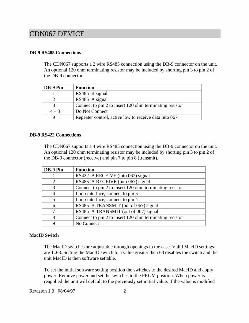
DB-9 RS485 Connections
The CDN067 supports a 2 wire RS485 connection using the DB-9 connector on the unit.An optional 120 ohm terminating resistor may be included by shorting pin 3 to pin 2 ofthe DB-9 connector.
DB-9 Pin Function 1 RS485 B signal 2 RS485 A signal 3 Connect to pin 2 to insert 120 ohm terminating resistor 4 – 8 Do Not Connect 9 Repeater control, active low to receive data into 067
DB-9 RS422 Connections
The CDN067 supports a 4 wire RS485 connection using the DB-9 connector on the unit.An optional 120 ohm terminating resistor may be included by shorting pin 3 to pin 2 ofthe DB-9 connector (receive) and pin 7 to pin 8 (transmit).
DB-9 Pin Function 1 RS422 B RECEIVE (into 067) signal 2 RS485 A RECEIVE (into 067) signal 3 Connect to pin 2 to insert 120 ohm terminating resistor 4 Loop interface, connect to pin 5 5 Loop interface, connect to pin 4 6 RS485 B TRANSMIT (out of 067) signal 7 RS485 A TRANSMIT (out of 067) signal 8 Connect to pin 2 to insert 120 ohm terminating resistor 9 No Connect
MacID Switch
The MacID switches are adjustable through openings in the case. Valid MacID settingsare 1..63. Setting the MacID switch to a value greater then 63 disables the switch and theunit MacID is then software settable.
To set the initial software setting position the switches to the desired MacID and applypower. Remove power and set the switches to the PRGM position. When power isreapplied the unit will default to the previously set initial value. If the value is modified

CDN067 DEVICE
Revision 1.3 08/04/97 3
by software the new value is retained in E2 memory and will be used in subsequent poweron sequences.
Data Rate Switch
The DeviceNet data rate switch is adjustable through openings in the case. Valid settingsare 125 kbit, 250 kbit and 500 kbit. Setting the switch to an invalid setting allows thebaud rate to be set in software.
To set the initial software setting position the switch to the desired data rate and applypower. Remove power and set the switch to the PRGM position. When power isreapplied the unit will default to the previously set initial value. If the value is modifiedby software the new value is retained in E2 memory and will be used in subsequent poweron sequences.
DeviceNet Indicator LED’s
The CDN067-2 includes two standard bi-color LED’s that conform to the ODVAspecification for Module and Network Status. During power up the LED’s willmomentary alternate between RED and GREEN. The Module Status LED should then goto a solid GREEN and the Network Status LED will BLINK GREEN until a DeviceNetconnection is established.
A RED Module Status LED indicates a module failure. A RED Network Status LEDindicates a network failure. Refer to the ODVA specifications for further details.
RS485/422 Activity LED’s
The CDN067 includes two bi-color LED’s to indicate current RS485/422 networkactivity. The TX LED will Flash GREEN whenever a packet is transmitted. The RX LEDwill Flash Green whenever a packet is received. A RED condition on either LEDindicates a fault has been detected (over-run).
Option Switch
The CDN067 includes a 10 position option switch which may be read through the deviceconfiguration object.
Specifications

CDN067 DEVICE
Revision 1.3 08/04/97 4
DeviceNet InterfacePower Requirements: 11 - 28 Vdc @ 50 mALoss of Ground: YesReverse Polarity: -30 VdcSignal Levels: ISO11898
RS485/422ESD Protection: +/- 10 kvOverload protection: +/- 30 VoltShort Circuit: IndefiniteOutput levels +/- 2.4 Volts (unloaded, typical)
EnvironmentalTemperature: 0-70 oCSize: 3.25 X 2.37 X 1.08Mounting: ½ inch tab, 3/16 diameter Mtg HoleEncapsulation: RTV Silicon Compound

CDN067 DEVICE
Revision 1.3 08/04/97 5
DeviceNet Information
The CDN067 (DeviceNet Serial Gateway) device operates as a slave on the DeviceNetnetwork. The unit supports Explicit Messages and Polled I/O Messages of the predefinedmaster/slave connection set. It does not support the Explicit Unconnected Message Manager(UCMM).
The device provides an RS422/RS485 serial interface, allowing serial information to be sentand received from peripheral devices. The RS422/RS485 serial information is buffered inan internal 64 byte receive FIFO, allowing the unit to operate asynchronous to theDeviceNet network. Similarly, information to be transmitted to the serial device is bufferedin a 64 byte serial fifo. The device may be configured to operate at a number of differentbaud rates and supports flow control and parity.
CDN067 firmware also provides additional support for BLOCK transfer of serial data. TheCDN067 may be programmed with a prefix/suffix delimiter character and willautomatically parse the incoming data stream into complete packets, ensuring that polledI/O scanners only receive complete data sets.
To further support polled I/O scanners it is possible to prepend a sequence number to eachtransaction. The CDN067 will only transmit serial data if the sequence number of the pollrequest is different than the previous poll request. Each poll response packet can alsoinclude a sequence number, which auto increments on each packet sent.
CDN067 devices support padded DeviceNet strings in which incoming strings may be leftor right justified with PAD characters to ensure that all packets are of a fixed length. Inaddition, the Stream object configuration (Maximum Receive Size and Maximum TransmitSize) affect the Produced and Consumed sizes of the POLL connection, allowing these to bereduced to minimize unnecessary bus traffic.
CDN067 also provides support to send the status byte in the poll response, and allow thestatus information to be cleared in the poll command. Changed firmware to only allowchanging of items that affect the produce and consume size when a poll connection is in thenon-established state.
CDN067 DEVICE
Revision 1.3 08/04/97 6
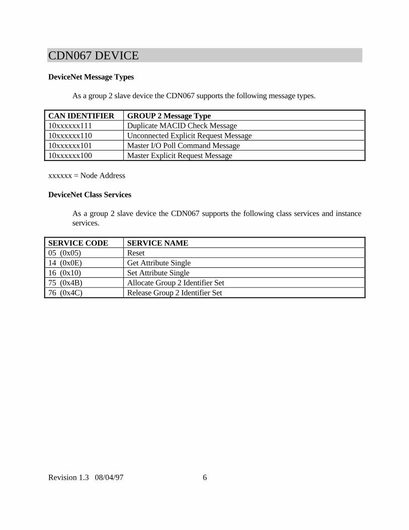
DeviceNet Message Types
As a group 2 slave device the CDN067 supports the following message types.
CAN IDENTIFIER GROUP 2 Message Type10xxxxxx111 Duplicate MACID Check Message10xxxxxx110 Unconnected Explicit Request Message10xxxxxx101 Master I/O Poll Command Message10xxxxxx100 Master Explicit Request Message
xxxxxx = Node Address
DeviceNet Class Services
As a group 2 slave device the CDN067 supports the following class services and instanceservices.
SERVICE CODE SERVICE NAME05 (0x05) Reset14 (0x0E) Get Attribute Single16 (0x10) Set Attribute Single75 (0x4B) Allocate Group 2 Identifier Set76 (0x4C) Release Group 2 Identifier Set

CDN067 DEVICE
Revision 1.3 08/04/97 7
DeviceNet Object Classes
The CDN067 device supports the following DeviceNet object classes.
CLASS CODE OBJECT TYPE01 (0x01) Identity02 (0x02) Router03 (0x03) DeviceNet04 (0x04) Assembly05 (0x05) Connection64 (0x40) User defined serial interface
CDN067 DEVICE
Revision 1.3 08/04/97 8
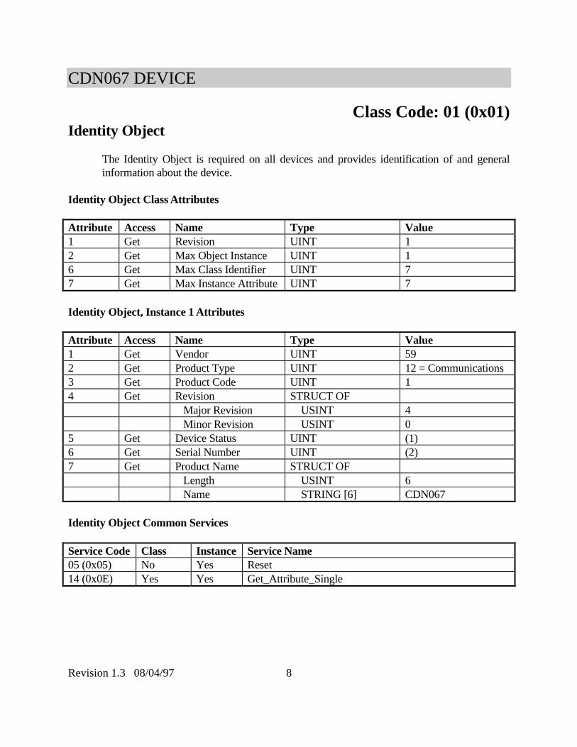
Class Code: 01 (0x01)Identity Object
The Identity Object is required on all devices and provides identification of and generalinformation about the device.
Identity Object Class Attributes
Attribute Access Name Type Value1 Get Revision UINT 12 Get Max Object Instance UINT 16 Get Max Class Identifier UINT 77 Get Max Instance Attribute UINT 7
Identity Object, Instance 1 Attributes
Attribute Access Name Type Value1 Get Vendor UINT 592 Get Product Type UINT 12 = Communications3 Get Product Code UINT 14 Get Revision STRUCT OF
Major Revision USINT 4 Minor Revision USINT 0
5 Get Device Status UINT (1)6 Get Serial Number UINT (2)7 Get Product Name STRUCT OF
Length USINT 6 Name STRING [6] CDN067
Identity Object Common Services
Service Code Class Instance Service Name05 (0x05) No Yes Reset14 (0x0E) Yes Yes Get_Attribute_Single

CDN067 DEVICE
Revision 1.3 08/04/97 9
(1) Device Status
bit 0 owned 0=not owned1=owned (allocated)
bit 1 reserved 0 bit 2 configured 0 bit 3 reserved 0 bit 4-7 vendor specific 0 bit 8 minor cfg fault 0=no fault 1=minor fault bit 9 minor dev.fault 0=no fault 1=minor device fault bit 10 major cfg.fault 0=no fault 1=major cfg. fault bit 11 major dev.fault 0=no fault 1=major device fault bit 12-15 reserved 0
2) Unique Serial Number

CDN067 DEVICE
Revision 1.3 08/04/97 10
Class Code: 02 (0x02)Router Object
The Message Router Object provides a messaging connection point through which a Clientmay address a service to any object class or instance residing in the physical device.
Router Object Class Attributes
Attribute Access Name Type Value1 Get Revision UINT 16 Get Max Class Identifier UINT 77 Get Max Instance Attribute UINT 2
Router Object, Instance 1 Attributes
Attribute Access Name Type Value2 Get Number of
ConnectionsUINT 2
Router Object Common Services
Service Code Class Instance Service Name14 (0x0E) Yes Yes Get_Attribute_Single

CDN067 DEVICE
Revision 1.3 08/04/97 11
Class Code: 03 (0x03)DeviceNet Object
DeviceNet Object Class Attributes
Attribute Access Name Type Value1 Get Revision UINT 2
DeviceNet Object, Instance 1 Attributes
Attribute Access Name Type Value1 Get/Set MACID USINT (1)2 Get/Set Baud Rate USINT (2)3 Get/Set Bus Off Interrupt BOOL (3)4 Get/Set Bus Off Counter USINT (4)5 Get/Spc Allocation Information STRUCT of (5)
Choice Byte BYTE Master Node Addr. USINT
DeviceNet Object Common Services
Service Code Class Instance Service Name14 (0x0E) Yes Yes Get_Attribute_Single16 (0x10) No Yes Set_Attribute_Single75 (0x4B) No Yes Allocate Master/Slave76 (0x4C) No Yes Release Master/Slave Attribute 1 – MacID Settable only if the MacID switches are set to a value greater than 63. Value returned will be
switch value if less than 64 or the last value set.

CDN067 DEVICE
Revision 1.3 08/04/97 12
Attribute 2 – Baud Rate
Settable only if the Baud Rate switch is set to a value greater than 2. Value returned will beswitch value if less than 4 or the last value set.
Switch/Value Speed 0 125 kbits 1 250 kbits 2 500 kbits 3 Software Selectable
Attribute 3 – Bus Off Interrupt
Bus Off Interrupt (BOI) determines action if Bus Off state encountered. Following valuesare supported:
BOI Action
0 Hold chip in OFF state (default) 1 If possible reset CAN chip
Attribute 4 – Bus Off Counter
Bus Off Counter will be forced to 0 whenever set regardless of the data value provided.
Attribute 5 – Allocation Byte
Allocation_bytebit 0 explicitset to 1 to allocatebit 1 polled set to 1 to allocatebit 2 strobed(not supported)bit 3-7 reserved (always 0)

CDN067 DEVICE
Revision 1.3 08/04/97 13
Class Code: 04 (0x04)Assembly Object
The Assembly Objects bind attributes of multiple objects to allow data to or from eachobject to be sent or received over a single connection.
Assembly Object Class Attributes
Attribute Access Name Type Value1 Get Revision UINT 12 Get Max Class ID UINT 2
Assembly Object, Instance 1 Attributes
Attribute Access Name Type Value3 Get Data Stream (Input) see notes (1)
Assembly Object, Instance 2 Attributes
Attribute Access Name Type Value3 Get/Set Data Stream (Output) see notes (2)
Assembly Object Common Services
Service Code Class Instance Service Name14 (0x0E) Yes Yes Get_Attribute_Single16 (0x10) Yes Yes Set_Attribute_Single
Attribute 1 – Input Data
The input data stream is structured as either an array of bytes or as a SHORT_STRINGconsisting of a single byte length field and ‘n’ data bytes. Refer to the serial stream objectclass 64 for further information.
Attribute 2 – Output Data
The output data stream is structured as either an array of bytes or as a SHORT_STRINGconsisting of a single byte length field and ‘n’ data bytes. Refer to the serial stream objectclass 64 for further information.

CDN067 DEVICE
Revision 1.3 08/04/97 14
Class Code: 05 (0x05)Connection Object
The Connection Objects manage the characteristics of each communication connection. Asa Group II Only Slave device the unit supports one explicit message connection and a POLLmessage connection.
Connection Object Class Attributes
Attribute Access Name Type Value1 Get Revision UINT 1
Connection Object, Instance 1 Attributes (Explicit Message)
Attribute Access Name Type Value1 Get State USINT (1)2 Get Instance Type USINT 0 = Explicit Message3 Get Transport Class
TriggerUSINT 0x83
4 Get Production Connection UINT (2)5 Get Consumed Connection UINT (2)6 Get Initial Comm. Char. USINT 0x217 Get Production Size UINT 678 Get Consumed Size UINT 719 Get/Set Expected Packet Rate UINT Default 2500 msec12 Get/Set Timeout Action USINT (3)13 Get Prod. Path Length USINT 014 Get Production Path (null)15 Get Cons. Path Length USINT 016 Get Consumed Path (null)17 Get Production Inhibit UINT 0
Connection Object, Instance 2 Attributes (POLL connection)
Attribute Access Name Type Value1 Get State USINT (1)2 Get Instance Type USINT 1 = I/O Message3 Get Transport Class
TriggerUSINT 0x82

CDN067 DEVICE
Revision 1.3 08/04/97 15
4 Get Production Connection UINT (2)5 Get Consumed Connection UINT (2)6 Get Initial Comm. Char. USINT 0x17 Get Production Size UINT See Stream Object8 Get Consumed Size UINT See Stream Object9 Get/Set Expected Packet Rate UINT Default 2500 msec12 Get/Set Timeout Action USINT (3)13 Get Prod. Path Length USINT 614 Get Production Path STRUCT of
Log. Seg., Class USINT 0x20 Class Number USINT 0x04 Log.Seg., Instance USINT 0x24 Instance Number USINT 0x01 Log.Seg., Attribute USINT 0x30 Attribute Number USINT 0x03
15 Get Cons. Path Length USINT 616 Get Production Path STRUCT of
Log. Seg., Class USINT 0x20 Class Number USINT 0x04 Log.Seg., Instance USINT 0x24 Instance Number USINT 0x02 Log.Seg., Attribute USINT 0x30 Attribute Number USINT 0x03
17 Get Production Inhibit UINT 0
Connection Class Common Services
Service Code Class Instance Service Name05 (0x05) Yes Yes Reset14 (0x0E) Yes Yes Get_Attribute_Single16 (0x10) No Yes Set_Attribute_Single
(1) Connection States:
0 = non-existent1 = configuring3 = established4 = timed out

CDN067 DEVICE
Revision 1.3 08/04/97 16
(2) Connection ID's:
Connection 1 Produced Connection ID: 10xxxxxx011Connection 1 Consumed Connection ID: 10xxxxxx100Connection 2 Produced Connection ID: 01111xxxxxxConnection 2 Consumed Connection ID: 10xxxxxx101
xxxxxx = Node Address.
(3) Watch Dog TimeOut Activity:
0 = Timeout (Explicit Messaging default)1 = Auto Delete2 = Auto Reset (I/O Message default)
(4) If no data is available during the poll response a 0 length (null) packet is returned.

CDN067 DEVICE
Revision 1.3 08/04/97 17
Class Code: 64 (0x40)
Serial Stream Object
The Serial Stream Object model supports a bi-directional serial stream of data. The objectincludes the transmit FIFO, the receive FIFO and the serial channel configuration attributes.
Serial Stream Class Attributes
Attribute Access Name Type Value1 Get Revision UINT 22 Get Max Object Instance UINT 16 Get Max Class Identifier UINT 77 Get Max Instance Attribute UINT 24
Serial Stream Object, Instance 1 Attributes
Attribute Access Name Type Value3 Get Receive Data See Notes (3)4 Set Transmit Data See Notes (4)5 Get/Set Status USINT (5)6 Get/Set Baud Rate USINT (6)7 Get/Set Parity USINT (7)8 Get Data Size USINT (8)9 Get Stop Bits USINT (9)10 Get/Set Flow Control USINT (10)11 Get/Set Receive Count USINT (11)12 Get/Set Transmit Count USINT (12)13 Get/Set Maximum Receive
SizeUSINT (13) *
14 Get/Set Data Format USINT (14) *15 Get/Set Block Mode USINT (15) *16 Get/Set Receive Delimiter USINT (16) 17 Get/Set Pad Char CHAR (17) 18 Get/Set Maximum Transmit
sizeUSINT (18) *
19 Get/Set Idle String SHORT_STRING (19)20 Get/Set Fault String SHORT_STRING (20)21 Get/Set Status Enable USINT (21)*
CDN067 DEVICE
Revision 1.3 08/04/97 18
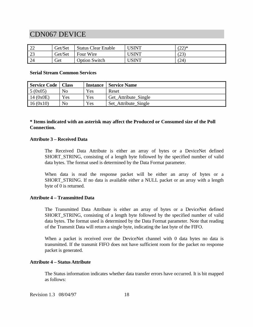
22 Get/Set Status Clear Enable USINT (22)*23 Get/Set Four Wire USINT (23)24 Get Option Switch USINT (24)
Serial Stream Common Services
Service Code Class Instance Service Name5 (0x05) No Yes Reset14 (0x0E) Yes Yes Get_Attribute_Single16 (0x10) No Yes Set_Attribute_Single
* Items indicated with an asterisk may affect the Produced or Consumed size of the PollConnection.
Attribute 3 – Received Data
The Received Data Attribute is either an array of bytes or a DeviceNet definedSHORT_STRING, consisting of a length byte followed by the specified number of validdata bytes. The format used is determined by the Data Format parameter.
When data is read the response packet will be either an array of bytes or aSHORT_STRING. If no data is available either a NULL packet or an array with a lengthbyte of 0 is returned.
Attribute 4 – Transmitted Data
The Transmitted Data Attribute is either an array of bytes or a DeviceNet definedSHORT_STRING, consisting of a length byte followed by the specified number of validdata bytes. The format used is determined by the Data Format parameter. Note that readingof the Transmit Data will return a single byte, indicating the last byte of the FIFO.
When a packet is received over the DeviceNet channel with 0 data bytes no data istransmitted. If the transmit FIFO does not have sufficient room for the packet no responsepacket is generated.
Attribute 4 – Status Attribute
The Status information indicates whether data transfer errors have occurred. It is bit mappedas follows:

CDN067 DEVICE
Revision 1.3 08/04/97 19
Status Byte Interpretation 0 Transmit channel blocked 1 Transmit Fifo Empty 2 * Receive Parity Error 3 Receive Fifo empty 4 * Receive Overflow 5 * Framing Error 6 * Transmit FIFO Overflow
* Writing any value to the Status field will clear the error bits.
Attribute 6 – Baud Rate
The Baud Rate (attribute 6) may be set by software.
Baud Rate Speed 0 9600 Baud 1 4800 Baud 2 2400 Baud 3 1200 Baud 4 600 Baud 5 300 Baud 6 19.2 kbaud
Attribute 7 – Parity
The Parity may be set by software. Note that setting the parity to 0 forces the data lengthsize to 8. Setting the parity to non-zero forces the data length size to 7.
Parity Interpretation 0 No Parity 1 Even Parity 2 Odd Parity 3 N/A 4 N/A 5 Force to 1 6 Force to 0

CDN067 DEVICE
Revision 1.3 08/04/97 20
Attribute 8 – Data Size
The Data size is read only. The CDN067 serial channel always processes 8 information bits.If parity is set to 0 (no parity) 8 data bits are transmitted/received. If the parity is set to anon-zero value then only 7 data bits are transmitted and the 8th bit is used for the parity bit.The Data Size field is read only.
Attribute 9 – Stop Bits
The Stop bits (Attribute 9) is read only. The CDN067 serial channel always operates with 1stop bit. The Stop Bits field is read only and fixed at 1 stop bit.
Attribute 10 – Flow Control
Flow control may be set by software.
Flow Control Interpretation 0 No Flow Control 1 X-ON/X-OFF flow (4 wire mode)
(4 Wire Mode Only) If the flow control is set to 1 the ASCII standard X-OFF (CTRL S)character will force the transmit function to block. Characters will be buffered in thetransmit FIFO until the transmitter is re-enabled using the X-ON (CTRL Q) character. Notethat the CTRL-S and CTRL-Q characters will be stripped from the incoming data stream,making this protocol unsuitable for binary data transmission.
When the receive FIFO is full the CDN067 will transmit an X-OFF character. An X-ONcharacter is transmitted when the number of characters in the receive FIFO drops below50%.
Attribute 11 – Receive Count
The Receive Count (Attribute 11) indicates the number of characters currently available inthe receive FIFO. Writing any value will flush the receive FIFO.
Attribute 12 – Transmit Count
The Transmit Count indicates the number of characters currently in the transmit FIFO.Writing any value will flush the transmit FIFO.

CDN067 DEVICE
Revision 1.3 08/04/97 21
Attribute 13 – Maximum Receive Size
The Maximum Receive Size indicates the maximum number of data bytes to be returnedwhen the receive FIFO is read (attribute 3) either using EXPLICIT messages or through thePOLL connection. Setting this attribute will automatically reset the Produced Connectionsize as:
Connection size = Max Rcv Size (Maximum size is 64)+ 1 (if Status Byte enabled)+ 1 (if String Format enabled)+ 1 (if Receive Seq. Num. enabled)
The maximum connection size is 67 bytes. This attribute affects the produce size, and isonly settable when the the poll connection is in the non-established state.
Attribute 14 – Data Format
The Data Format control byte determines the type of data strings transferred over theDeviceNet channel which may be either an array of bytes or a DeviceNet definedSHORT_STRING, consisting of a length byte followed by the specified number of validdata bytes. Note that the data length byte does not appear on the serial channel. The Dataformat control byte also determines whether the parity information is retained in thereceive FIFO. If the bit is cleared then the parity information is retained. If set, the parityinformation is overwritten with a 0, ensuring that only valid ASCII characters (0-7FH)appear in the FIFO.
Bit 7 Bit 6 Bit 5 Bit 4 Bit 3 Bit 2 Bit 1 Bit 0 X X X X PADR PL/R Strip Parity String Format
String Format Interpretation
0 Process FIFO packets as SHORT_STRING variables 1 Process FIFO packets as an array of bytes. The array length
implicitlydefines the number of valid bytes.
Strip Parity Interpretation
0 Retain Parity information in receive FIFO1 Set MSB of receive FIFO data to 0
PL/R Interpretation

CDN067 DEVICE
Revision 1.3 08/04/97 22
0 Left justify received character string if PADR set1 Right justify received character string if PADR set
PADR Interpretation0 Do not attempt to PAD received characters1 Pad received characters strings with PADCHAR
If the PADR bit is set in block mode with the Strip Delimiter bit clear the Pad characterswill be inserted between the last valid data bit and the end of the packet.
This attribute affects the produce and consume size, and is only settable when the thepoll connection is in the non-established state.
Attrribute 15 – Block Mode
The Block Mode control byte determines the whether the unit preparses the RS422/485serial stream, whether block sequence numbers are pre-pended to the DeviceNet packetsand whether received data is retransmitted on subsequent POLL requests. The control bytehas the following format:
Bit 7 Bit 6 Bit 5 Bit 4 Bit 3 Bit 2 Bit 1 Bit 0 X Sync ReSend Enable Xmit
Seq. NumberEnable Rcv.Seq.Number
DelimiterEnable
StripDelimiter
Pre/PostDelimiter
Pre/Post InterpretationDelimiter
0 Delimiter (if enabled) occurs at the end of the packet.1 Delimiter (if enabled) occurs at the start of the packet. The packet
length is limited to the <Max Receive Size> length. Excesscharacters are discarded.
Strip Delimiter Interpretation
0 The delimiter character appears in the response packet.1 The delimiter character is removed from the response packet.
Delimiter Enable Interpretation
0 Disable the delimit character function

CDN067 DEVICE
Revision 1.3 08/04/97 23
1 Enable the delimit character function

CDN067 DEVICE
Revision 1.3 08/04/97 24
Enable Rcv.Seq.Num Interpretation0 Disable the receive sequence number1 Each response packet will have a sequential number pre-pended to
allow the scanner to detect new response data.
Enable Xmt.Seq.Num Interpretation
0 Disable the transmit sequence number1 The first byte of the poll request must contain a number different
than the last request to allow the updating of the scanner data fieldwithout generating erroneous data on the RS422/RS485 data.
Resend Interpretation0 Valid data is only sent once1 Valid data is resent during subsequent Poll requests until a new
string of valid data is received on the RS422/RS485 serial channel.
Sync Interpretation0 Do not apply synchronous Hand-shake protocol1 Apply synchronous Hand-shake protocol
When a CDN067 is configured with both <string> formatting and sequence numbers thesequence number is applied as the first byte and the string length information is contained inthe second data byte.
If the delimiter function is enabled the receive packet size may have an affect on the dataresponses. If the Post Delimiter field is zero the CDN067 will not transmit any responsedata until the delimiter character is detected or until <receive data size> bytes are available.If the receive data size is set less than the number of available characters the first pollresponse will contain the first <receive data size> bytes and the second poll response willreceive the remaining characters up to delimiter.
If the Post Delimiter field is 1 the CDN067 will not transmit any response data until adelimiter is detected AND:
1) more than <receive data size> bytes have been received, or2) another delimiter is detected
Characters in excess of the receive data size are discarded.

CDN067 DEVICE
Revision 1.3 08/04/97 25
If the Resend bit is set the device will resend data on subsequent Poll requests until anothervalid data packet has been received.
The Sync bit enables the Synchronous Hand-shake protocol which provides further controlover the sequence numbers during Poll Request/Response transactions to allow the Masterto determine if a) a previous Poll Request packet has been accepted and b) the current PollResponse represents a new data string.
When the Sync bit is set to 1 the Xmt.Seq.Num and Rcv.Seq.Num bits will be forced to 1.
The Xmt.Seq.Num is received in the Poll Request and is interpreted as 2 four bit numbers:
Bit Numbers 4-7 Bit Numbers 0-3RcceiveAcknowledgeNumber TransmitRequestNumber
The TransmitRequestNumber acts in the same way as the Xmt.Seq.Num described above.The CDN067 will ignore any data in the Poll Request until the TransmitRequestNumber isdifferent than previously received TransmitRequestNumber. If a value of 0 is received thecurrent data (if any) will be ignored. A 0 acts as a ‘reset’ function for theTransmitRequestNumber.
The ReceiveAcknowledgeNumber is compared against the ReceiveRequestNumber (seebelow) and if equal it releases the current receive data buffer, allowing the CDN067 to sendnew information. A value of 0 will reset the ReceiveRequestNumber, acting as a resetfunction.
The Rcv.Seq.Num is transmitted in the Poll Response and is interpreted as 2 four bitnumbers:
Bit Numbers 4-7 Bit Numbers 0-3ReceiveRequestNumber TransmitAcknowledgeNumber
The TransmitAcknowledgeNumber will be the same value as the most recently processedTransmitRequestNumber. When a poll request packet is received theTransmitRequestNumber is compared to the last TransmitAcknowledgeNumber and ifdifferent the data contained in the poll request is transmitted (see above). TheTransmitRequestNumber is then transferred to the TransmitAcknowledgeNumber to notifythe Master that the transaction has been processed.
The ReceiveRequestNumber is used by the CDN067 to indicate to the Master that the pollresponse contains new data. The CDN067 will increment the most previous

CDN067 DEVICE
Revision 1.3 08/04/97 26
ReceiveAcknowledgeNumber (see above) and return it in the poll response if new data isavailable. Note that the CDN067 will generate numbers in the range 1..15, reserving 0 asthe reset value.
The Sync mode is typically used with a ‘Scanner’ that generates continuous poll requests.During the first poll request (possibly no valid data) the Xmt.Seq.Num should be set to avalue of 00, resetting the receive handshaking logic on the CDN067. If no receive data isavailable the poll response will have the Rcv.Seq.Num set to ?0. If data is available theCDN067 will generate a poll response with the Rcv.Seq.Num set to ?1 with the associateddata contained in the response packet. Further data will be buffered until the Scannergenerates a poll request with a Xmt.Seq.Num with a value of ?1, acknowledging the receiptand processing of the previous poll. The Scanner should increment theReceiveAcknowledgeNumber after processing each poll response, wrapping from 15 to 1.
During transmission, the scanner application code may build the request message inmemory and then increment the TransmitRequestNumber (1..15). This allows thebackground scanner function to send ‘partially complete’ poll requests without generatingextraneous RS422/RS485 transmissions. When the scanner application code detects that theTransmitAcknowledgeNumber received as part of the poll response matches the previousTransmitRequestNumber it indicates that the scanner has successfully transmitted theprevious poll data and the application may proceed to build new RS422/RS485 transmitdata.
This attribute adds 1 byte to the produce and consume size, and is only settable when thethe poll connection is in the non-established state.
Attribute 16 - Delimiter
The Delimiter character determines the start or end of packet character for theRS422/RS485 channel. It is only effective if the Delimiter Enable bit in the BlockControl byte is set.
Attribute 17 – Pad Character
The Pad Char is used to pad string formatted receive data. It is typically set to ASCII<space> (020H) or an ASCII <null> (0).
Attribute 18 – Maximum Transmit Size
The Maximum Transmit Size indicates the maximum number of data bytes to betransmitted across the RS422/RS485 channel. Setting this attribute will automatically resetthe Poll Consumed Connection size as:

CDN067 DEVICE
Revision 1.3 08/04/97 27
Connection size = Max Xmt Size (Maximum value 64)+ 1( if Status Clear enabled)+ 1 (if String Format enabled)+ 1 (if Transmit Seq. Num. enabled)
The maximum connection size is 67 bytes.
This attribute affects the consume size, and is only settable when the the poll connectionis in the non-established state.
Attribute 19 – Idle String
The Idle String will be transmitted on the RS422/RS485 serial channel if the devicereceives a ‘receive_idle’ (null Poll). If the string length by is set to 0 no data will betransmitted.
Attribute 20 – Fault String
The Fault String will be transmitted on the RS422/RS485 serial channel if the deviceexperiences a connection timeout. If the string length by is set to 0 no data will betransmitted.
Attribute 21 – Status Enable
The Status Enable inserts the serial status (Class 64 Instance 1 Attribute 5) as the first byteof the poll response when set to a non-zero value.
This attribute adds 1 byte to the produce size, and is only settable when the the pollconnection is in the non-established state.
Attribute 22 – Status Clear Enable
The Status Clear Enable allows the first byte in the poll command to clear the status byte(when status clear byte, the first byte in the poll is not equal to 0) or not change the status(status clear byte, the first byte in the poll is =0 ).
This attribute adds 1 byte to the consume size, and is only settable when the the pollconnection is in the non-established state.
Attribute 23 – Four Wire Enable

CDN067 DEVICE
Revision 1.3 08/04/97 28
The Four Wire Enable (Attribute 23) change the serial protocol to 4 wire RS-422communications when set. When clear the communication protocol is 2-wire RS-485.
Attribute 24 – Option Switch
The Option Switch provides a rotary switch reading that is available to the DeviceNetuser.