Embed Size (px)
Citation preview
Part Number MN/CDM550T.IOM Revision 1.3
CDM-550T Satellite Modem (Viterbi/Sequential/RS/Turbo)
Installation and Operation Manual (For Firmware V1.19 or higher)

Copyright © Comtech EF Data, 2000. All rights reserved. Printed in the USA. Comtech EF Data, 2114 West 7th Street, Tempe, Arizona 85281 USA, (480) 333-2200, FAX: (480) 333-2161.
CDM-550T Satellite Modem (Viterbi/Sequential/RS/Turbo)
Installation and Operation Manual (For Firmware V1.19 or higher)
Part Number MN/CDM550T.IOM
Revision 1.3 July 9, 2001
Comtech EF Data is an ISO 9001 Registered Company.
ii Rev.1.3
Customer Support
Contact the Comtech EF Data Customer Support Department for: • Product support or training • Information on upgrading or returning a product • Reporting comments or suggestions concerning manuals A Customer Support representative may be reached at:
Comtech EF Data Attention: Customer Support Department 2114 West 7th Street Tempe, Arizona 85281 USA (480) 333-2200 (Main Comtech EF Data Number) (480) 333-4357 (Customer Support Desk) (480) 333-2161 FAX
or, E-Mail can be sent to the Customer Support Department at:
[email protected] Contact us via the web at www.comtechefdata.com.
1. To return a Comtech EF Data product (in-warranty and out-of-warranty) for repair or replacement:
2. Request a Return Material Authorization (RMA) number from the Comtech EF
Data Customer Support Department. 3. Be prepared to supply the Customer Support representative with the model
number, serial number, and a description of the problem. 4. To ensure that the product is not damaged during shipping, pack the product in
its original shipping carton/packaging. 5. Ship the product back to Comtech EF Data. (Shipping charges should be
prepaid.) For more information regarding the warranty policies, see Warranty Policy, p. xii.
Rev.1.3 iii
Table of Contents
Customer Support .................................................................................................................................................... iii
Overview of Changes to Previous Edition ....................................................................................................... viiiviii
About this Manual ............................................................................................................................................. viiiviii
Conventions and References ............................................................................................................................. viiiviii Metric Conversion........................................................................................................................................... viiiviii Cautions and Warnings ................................................................................................................................... viiiviii Recommended Standard Designations ................................................................................................................. ixix Reporting Comments or Suggestions Concerning this Manual............................................................................ ixix
Safety Notices .......................................................................................................................................................... ixix Electrical Safety ................................................................................................................................................... ixix Fuses..................................................................................................................................................................... ixix Environmental ........................................................................................................................................................ xx Installation.............................................................................................................................................................. xx Telecommunications Terminal Equipment Directive............................................................................................. xx EMC (Electromagnetic Compatibility) .................................................................................................................. xx
Warranty Policy................................................................................................................................................... xiixii Limitations of Warranty .................................................................................................................................... xiixii Exclusive Remedies .......................................................................................................................................... xiixii Disclaimer ......................................................................................................................................................... xiixii
CHAPTER 1. INTRODUCTION .................................................................................. 1–1
1.1 Standard Features ......................................................................................................................................1–1 1.1.1 AUPC...................................................................................................................................................1–2 1.1.2 Software...............................................................................................................................................1–2 1.1.3 Verification ..........................................................................................................................................1–2 1.1.4 Data Interfaces .....................................................................................................................................1–3
1.2 Options ........................................................................................................................................................1–3
Preface CDM-550T Satellite Modem
iv Rev.1.3
1.3 Compatibility ..............................................................................................................................................1–3
1.4 New in This Release....................................................................................................................................1–4
CHAPTER 2. INSTALLATION.................................................................................... 2–1
2.1 Unpacking ...................................................................................................................................................2–1
2.2 Mounting .....................................................................................................................................................2–1
2.3 Configuration..............................................................................................................................................2–2
2.4 Select Internal IF Loop ..............................................................................................................................2–2
2.5 Connect External Cables............................................................................................................................2–2
CHAPTER 3. FUNCTIONAL DESCRIPTION ............................................................. 3–1
CHAPTER 4. PHYSICAL DESCRIPTION .................................................................. 4–1
4.1 Front Panel..................................................................................................................................................4–2
4.2 Rear Panel ...................................................................................................................................................4–3
CHAPTER 5. CONNECTOR PINOUTS...................................................................... 5–1
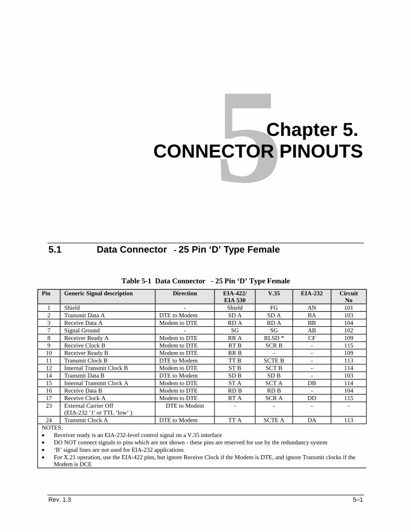
5.1 Data Connector - 25 Pin ‘D’ Type Female .............................................................................................5–1
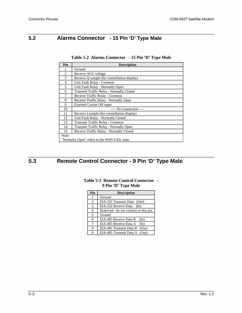
5.2 Alarms Connector - 15 Pin ‘D’ Type Male.............................................................................................5–1
5.3 Remote Control Connector - 9 Pin ‘D’ Type Male ................................................................................5–1
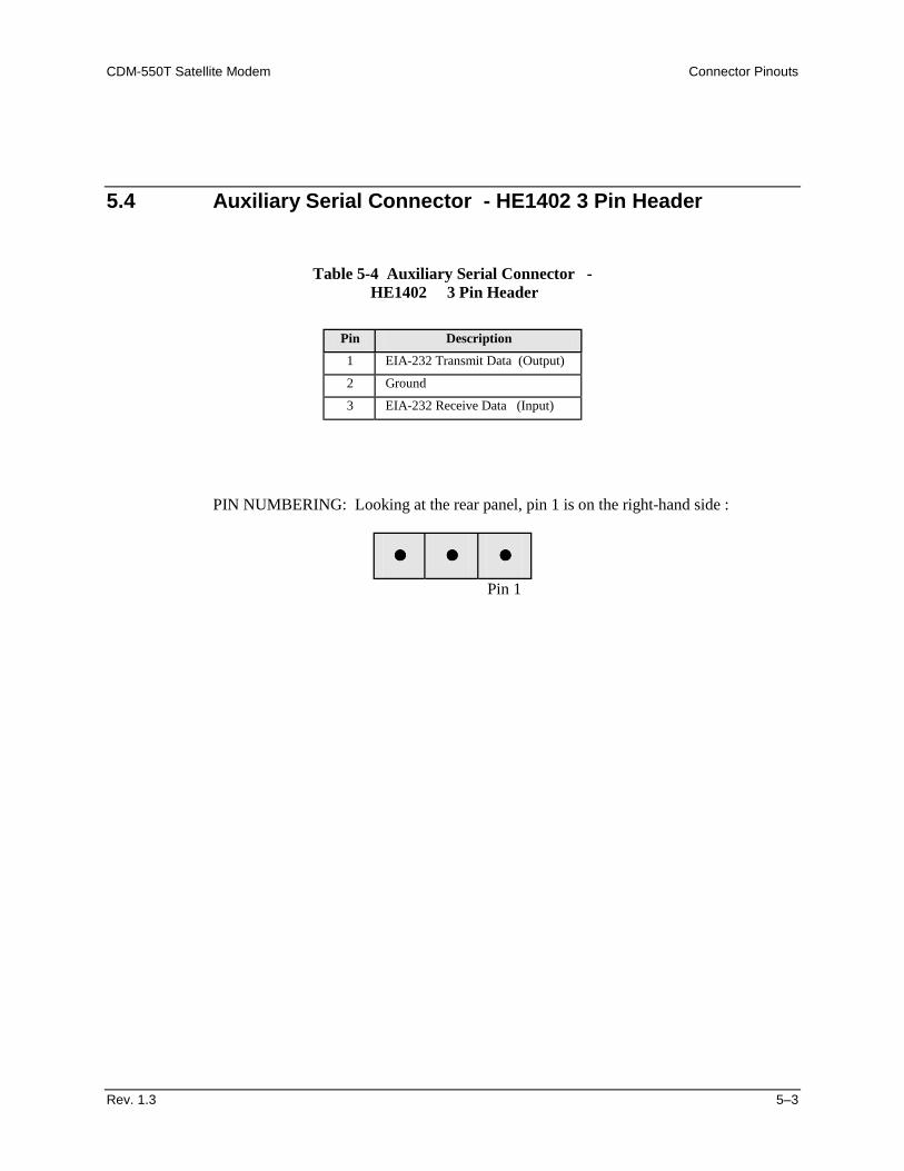
5.4 Auxiliary Serial Connector - He1402 3 Pin Header...............................................................................5–2
CHAPTER 6. FRONT PANEL OPERATION .............................................................. 6–1
6.1 Description ..................................................................................................................................................6–1
6.2 Menu Trees .................................................................................................................................................6–2 6.2.1 Opening Screen....................................................................................................................................6–2 6.2.2 Select ...................................................................................................................................................6–4 6.2.3 Config: .................................................................................................................................................6–5 6.2.4 TEST..................................................................................................................................................6–28 6.2.5 INFO (Information) ...........................................................................................................................6–30 6.2.6 MONIT (Monitor) .............................................................................................................................6–33 6.2.7 STORE/LD (Store/Load) ...................................................................................................................6–38 6.2.8 UTIL (Utility) ....................................................................................................................................6–41
CHAPTER 7. FORWARD ERROR CORRECTION OPTIONS .................................. 7–1
CDM-550T Satellite Modem Preface
Rev.1.3 v
7.1 Introduction ................................................................................................................................................7–1
7.2 Viterbi..........................................................................................................................................................7–1
7.3 Sequential ....................................................................................................................................................7–2
7.4 Reed-Solomon Outer Codec (Option) .......................................................................................................7–3
7.5 Turbo Product Codec (Option) .................................................................................................................7–4 7.1.1 End-to-End Processing Delay ..............................................................................................................7–6
7.6 Uncoded Operation (No FEC) ...................................................................................................................7–7
CHAPTER 8. OFFSET QPSK OPERATION .............................................................. 8–1
CHAPTER 9. EIA-232 DATA INTERFACE - ASYNCHRONOUS OPERATION ........ 9–1
9.1 Introduction ................................................................................................................................................9–1
9.2 ASYNC EIA-232 Specifications.................................................................................................................9–1
9.3 Setup ............................................................................................................................................................9–2
9.4 Other Considerations .................................................................................................................................9–2 9.4.1 Baud Rate Accuracy ............................................................................................................................9–2 9.4.2 Async Character Formats Using 1.5 Stop Bits.....................................................................................9–2
CHAPTER 10. CLOCKING....................................................................................... 10–1
10.1 Transmit Clocking ...............................................................................................................................10–1 10.1.1 Internal Clock ................................................................................................................................10–1 10.1.2 External Clock...............................................................................................................................10–1 10.1.3 Loop-Timed, RX=TX....................................................................................................................10–2 10.1.4 Loop-Timed, RX<>TX (Asymmetric Loop Timing) ....................................................................10–2
10.2 Receive Clocking ..................................................................................................................................10–2 10.2.1 Buffer Disabled .............................................................................................................................10–2 10.2.2 Buffer Enabled, RX=TX ...............................................................................................................10–2 10.2.3 Buffer Enabled, RX<>TX .............................................................................................................10–3
10.3 X.21 Notes .............................................................................................................................................10–3
10.4 Loop Timing With Sync EIA-232 .......................................................................................................10–3
CHAPTER 11. EDMAC CHANNEL .......................................................................... 11–1
11.1 Theory Of Operation ...........................................................................................................................11–1
11.2 M&C Connection .................................................................................................................................11–2
11.3 Setup Summary ....................................................................................................................................11–3
Preface CDM-550T Satellite Modem
vi Rev.1.3
CHAPTER 12. AUTOMATIC UPLINK POWER CONTROL .................................... 12–1
12.1 Introduction..........................................................................................................................................12–1
12.2 Setting AUPC Parameters ...................................................................................................................12–2 12.2.1 Target Eb/No .................................................................................................................................12–2 12.2.2 Max Range ....................................................................................................................................12–2 12.2.3 Alarm.............................................................................................................................................12–3 12.2.4 Demod Unlock ..............................................................................................................................12–3
12.3 Compensation Rate ..............................................................................................................................12–3
12.4 Monitoring ............................................................................................................................................12–4
CHAPTER 13. FLASH UPGRADING ....................................................................... 13–1
CHAPTER 14. SUMMARY OF SPECIFICATIONS ................................................. 14–1
14.1 MODULATOR.....................................................................................................................................14–1
14.2 Demodulator .........................................................................................................................................14–2
14.3 Automatic Uplink Power Control .......................................................................................................14–4
14.4 Data Interfaces .....................................................................................................................................14–4
14.5 Miscellaneous........................................................................................................................................14–4
14.6 Async Overhead ...................................................................................................................................14–5
14.7 Approvals..............................................................................................................................................14–5
CHAPTER 15. REMOTE CONTROL........................................................................ 15–1
15.1 Introduction..........................................................................................................................................15–1
15.2 EIA-485 .................................................................................................................................................15–1
15.3 EIA-232 .................................................................................................................................................15–2
15.4 Basic Protocol .......................................................................................................................................15–2
15.5 Packet Structure...................................................................................................................................15–3 15.5.1 Start Of Packet...............................................................................................................................15–3 15.5.2 Address..........................................................................................................................................15–3 15.5.3 Instruction Code ............................................................................................................................15–4 15.5.4 Instruction Code Qualifier .............................................................................................................15–4 15.5.5 Message Arguments ......................................................................................................................15–5 15.5.6 End Of Packet................................................................................................................................15–5
CDM-550T Satellite Modem Preface
Rev.1.3 vii
APPENDIX A. CABLE DRAWINGS ...........................................................................A–1
APPENDIX B. EB/NO MEASUREMENT ....................................................................B–1
APPENDIX C. ASYNC OVERHEAD OPTION............................................................C–1
Figures
FIGURE 4-1 FRONT AND REAR PANEL ............................................................................................................4–1 FIGURE 7-1 VITERBI DECODING.......................................................................................................................7–9 FIGURE 7-2 SEQUENTIAL DECODING 64 KBPS ..........................................................................................7–10 FIGURE 7-3 SEQUENTIAL DECODING 1024 KBPS .......................................................................................7–11 FIGURE 7-4 SEQUENTIAL DECODING 2048 KBPS .......................................................................................7–12 FIGURE 7-5 VITERBI WITH CONCATENATED RS 2200,200 OUTER CODE .............................................7–13 FIGURE 7-6 VITERBI WITH CONCATENATED RS 2200,200 OUTER CODE 512 KBPS ............................7–14 FIGURE 7-7 COMTECH EF DATA TURBO PRODUCT CODEC RATE 3/4 QPSK/OQPSK,
RATE 21/44 BPSK, RATE 5/16 BPSK..........................................................................................................7–15 FIGURE 7-8 DIFFERENTIAL ENCODING - NO FEC ......................................................................................7–16 FIGURE 10-1 TX CLOCK MODES......................................................................................................................10–4 FIGURE 10-2 RX CLOCK MODES......................................................................................................................10–5
Tables
TABLE 4-1. FRONT PANEL LED INDICATORS .................................................................................................4–2 TABLE 5-1 DATA CONNECTOR - 25 PIN ‘D’ TYPE FEMALE.......................................................................5–1 TABLE 5-2 ALARMS CONNECTOR - 15 PIN ‘D’ TYPE MALE......................................................................5–1 TABLE 5-3 REMOTE CONTROL CONNECTOR - 9 PIN ‘D’ TYPE MALE ...................................................5–1 TABLE 5-4 AUXILIARY SERIAL CONNECTOR - HE1402 3 PIN HEADER.................................................5–2 TABLE 7-1 VITERBI DECODING SUMMARY ...................................................................................................7–2 TABLE 7-2 SEQUENTIAL DECODING SUMMARY ..........................................................................................7–3 TABLE 7-3 CONCATENATED RS CODING SUMMARY..................................................................................7–4
Preface CDM-550T Satellite Modem
viii Rev.1.3
Overview of Changes to Previous Edition
• Offset QPSK mode added for Rate 3/4 Turbo • RF Loopback added to test modes • Async overhead mode added as an alternative to EDMAC (See Appendix C)
About this Manual
This manual provides installation and operation information for the Comtech EF Data CDM-550T satellite modem. This is a technical document intended for earth station engineers, technicians, and operators responsible for the operation and maintenance of the CDM-550T.
Conventions and References
Metric Conversion
Metric conversion information is located on the inside back cover of this manual. This information is provided to assist the operator in cross-referencing English to Metric conversions.
Cautions and Warnings
CAUTION
CAUTION indicates a hazardous situation that, if not avoided, may result in minor or moderate injury. CAUTION may also be used to indicate other unsafe practices or risks of property damage.
WARNING
WARNING indicates a potentially hazardous situation that, if not avoided, could result in death or serious injury.
CDM-550T Satellite Modem Preface
Rev.1.3 ix
Recommended Standard Designations
Recommended Standard (RS) Designations have been superseded by the new designation of the Electronic Industries Association (EIA). References to the old designations are shown only when depicting actual text displayed on the screen of the unit (RS-232, RS-485, etc.). All other references in the manual will be shown with the EIA designations
Reporting Comments or Suggestions Concerning this Manual
Comments and suggestions regarding the content and design of this manual will be appreciated. To submit comments, please contact the Comtech EF Data Customer Support Department.
Safety Notices
Electrical Safety
The CDM-550T Modem has been shown to comply with the following safety standard: EN 60950: Safety of Information Technology Equipment, including electrical
business machines The equipment is rated for operation over the range 100 - 240 volts AC. It has a maximum power consumption of 25 watts, and draws a maximum of 250 mA. The user should observe the following instructions:
Fuses
The CDM-550T is fitted with two fuses - one each for line and neutral connections. These are contained within the body of the IEC power inlet connector, behind a small plastic flap. • For 230 volt AC operation, use T0.5A, 20mm fuses. • For 115 volt AC operation, use T1A fuses, 20mm fuses. FOR CONTINUED OPERATOR SAFETY, ALWAYS REPLACE THE FUSES WITH THE CORRECT TYPE AND RATING.
Preface CDM-550T Satellite Modem
x Rev.1.3
Environmental
The CDM-550T must not be operated in an environment where the unit is exposed to extremes of temperature outside the ambient range 0 to 50°C, precipitation, condensation, or humid atmospheres above 95% RH, altitudes (un-pressurised) greater than 2000 metres, excessive dust or vibration, flammable gases, corrosive or explosive atmospheres. Operation in vehicles or other transportable installations which are equipped to provide a stable environment is permitted. If such vehicles do not provide a stable environment, safety of the equipment to EN60950 may not be guaranteed.
Installation
The installation and connection to the line supply must be made in compliance to local or national wiring codes and regulations. The CDM-550T is designed for connection to a power system that has separate ground, line and neutral conductors. The equipment is not designed for connection to power system which has no direct connection to ground. The CDM-550T is shipped with a line inlet cable suitable for use in the country of operation. If it is necessary to replace this cable, ensure the replacement has an equivalent specification. Examples of acceptable ratings for the cable include HAR, BASEC and HOXXX-X. Examples of acceptable connector ratings include VDE, NF-USE, UL, CSA, OVE, CEBEC, NEMKO, DEMKO, BS1636A, BSI, SETI, IMQ, KEMA-KEUR and SEV.
Telecommunications Terminal Equipment Directive
In accordance with the Telecommunications Terminal Equipment Directive 91/263/EEC, this equipment should not be directly connected to the Public Telecommunications Network.
EMC (Electromagnetic Compatibility)
The CDM-550T Modem has been demonstrated, by independent testing, to comply with the following standards: Emissions: EN 55022 Class B - Limits and methods of measurement of radio
interference characteristics of Information Technology Equipment. FCC Part 15 Class B
CDM-550T Satellite Modem Preface
Rev.1.3 xi
Immunity: EN 50082 Part 1 - Generic immunity standard, Part 1: Domestic, commercial and light industrial environment.
In order that the Modem continues to comply with these standards, observe the following instructions:
• Connections to the transmit and receive IF ports (BNC female connectors) should be made using a good quality coaxial cable - for example RG58/U (50 ohm) or RG59/U (75 ohm).
• All 'D' type connectors attached to the rear panel must have back-shells which
provide continuous metallic shielding. Cable with a continuous outer shield (either foil or braid, or both) must be used, and the shield must be bonded to the back-shell.
• The equipment must be operated with its cover on at all times. If it becomes
necessary to remove the cover, the user should ensure that the cover is correctly re-fitted before normal operation commences.
Preface CDM-550T Satellite Modem
xii Rev.1.3
Warranty Policy
This Comtech EF Data product is warranted against defects in material and workmanship for a period of two years from the date of shipment. During the warranty period, Comtech EF Data will, at its option, repair or replace products that prove to be defective. For equipment under warranty, the customer is responsible for freight to Comtech EF Data and all related custom, taxes, tariffs, insurance, etc. Comtech EF Data is responsible for the freight charges only for return of the equipment from the factory to the customer. Comtech EF Data will return the equipment by the same method (i.e., Air, Express, Surface) as the equipment was sent to Comtech EF Data.
Limitations of Warranty
The foregoing warranty shall not apply to defects resulting from improper installation or maintenance, abuse, unauthorized modification, or operation outside of environmental specifications for the product, or, for damages that occur due to improper repackaging of equipment for return to Comtech EF Data. No other warranty is expressed or implied. Comtech EF Data specifically disclaims the implied warranties of merchantability and fitness for particular purpose.
Exclusive Remedies
The remedies provided herein are the buyer's sole and exclusive remedies. Comtech EF Data shall not be liable for any direct, indirect, special, incidental, or consequential damages, whether based on contract, tort, or any other legal theory.
Disclaimer
Comtech EF Data has reviewed this manual thoroughly in order that it will be an easy-to-use guide to your equipment. All statements, technical information, and recommendations in this manual and in any guides or related documents are believed reliable, but the accuracy and completeness thereof are not guaranteed or warranted, and they are not intended to be, nor should they be understood to be, representations or warranties concerning the products described. Further, Comtech EF Data reserves the right to make changes in the specifications of the products described in this manual at any time without notice and without obligation to notify any person of such changes. If you have any questions regarding your equipment or the information in this manual, please contact the Comtech EF Data Customer Support Department.
Rev. 1.3 1–1
1Chapter 1. INTRODUCTION
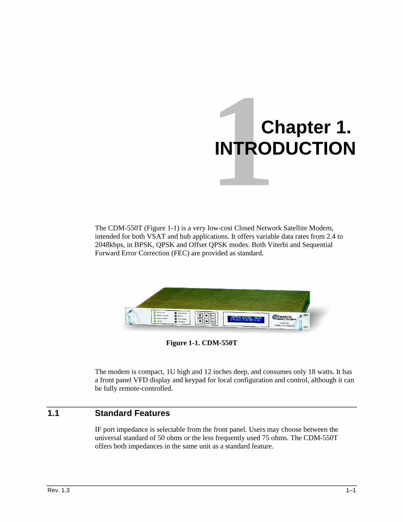
The CDM-550T (Figure 1-1) is a very low-cost Closed Network Satellite Modem, intended for both VSAT and hub applications. It offers variable data rates from 2.4 to 2048kbps, in BPSK, QPSK and Offset QPSK modes. Both Viterbi and Sequential Forward Error Correction (FEC) are provided as standard.
Figure 1-1. CDM-550T The modem is compact, 1U high and 12 inches deep, and consumes only 18 watts. It has a front panel VFD display and keypad for local configuration and control, although it can be fully remote-controlled.
1.1 Standard Features
IF port impedance is selectable from the front panel. Users may choose between the universal standard of 50 ohms or the less frequently used 75 ohms. The CDM-550T offers both impedances in the same unit as a standard feature.
Introduction CDM-550T Satellite Modem
1–2 Rev. 1.3
To facilitate network management, the CDM-550T incorporates EDMAC, an acronym for Embedded Distant-end Monitor And Control. In this mode, an additional 5% overhead is combined with the traffic data, (1.5% in Turbo BPSK modes) which permits M&C information to be added (transparently to the user), allowing access to the distant-end modem. This mode does not require any additional cabling at either the local or distant-end Modems - access to EDMAC is via the standard M&C control port. Full monitor and control is possible, and importantly, the on/off status of the carrier at the distant-end carrier can be controlled.
1.1.1 AUPC
An important innovation in the CDM-550T is the addition of Automatic Uplink Power Control (AUPC). This feature enables the modem to automatically adjust its output power to maintain the Eb/No of the remote end of the satellite link constant. This provides protection against rain fading, a particularly severe problem with Ku-band links. To accomplish this, the framed (EDMAC) mode of operation must be used, and the distant end modem constantly sends back information about the demodulator Eb/No using reserved bytes in the overhead structure. Using the Eb/No, the local modem then adjusts its output power, and hence, a closed-loop feedback system is created over the satellite link. A benefit of this feature is that whenever framed operation is selected, the remote demodulator’s Eb/No can be viewed from the front panel display of the local modem. Note that both EDMAC and AUPC can be used simultaneously.
1.1.2 Software
The internal software is both powerful and flexible, permitting storage and retrieval of up to 10 different modem configurations. The modem uses ‘flash memory’ technology internally, and new firmware can be uploaded to the unit from an external PC. This simplifies software upgrading, and updates can now be sent via the Internet, E-mail, or on disk. The upgrade can be performed without opening the unit, by simply connecting the modem to the serial port of a computer.
1.1.3 Verification
The unit includes many test modes and loopbacks for rapid verification of the correct functioning of the unit. Of particular note is the IF loopback, which permits the user to perform a quick diagnostic test without having to disturb external cabling. During the loopback, all of the receive configuration parameters are temporarily changed to match those of the transmit side. When normal operation is again selected, all of the previous values are restored.
CDM-550T Satellite Modem Introduction
Rev. 1.3 1–3
1.1.4 Data Interfaces
The CDM-550T includes, as standard, a universal data interface which eliminates the need to exchange interface cards for different applications. The interfaces offered include
• EIA-422 (EIA530) DCE • V.35 DCE • Synchronous EIA-232 DCE • Asynchronous EIA-232 (at data rates up to 56 kbaud) • X.21 DTE and DCE
1.2 Options
As an external option, a G.703 interface (Comtech EFData Model Number CIC-50), operating at T1 (1544 kbps) and E1 (2048 kbps) is available. Two optional Forward Error Correction Codecs can be supplied. The first, a Reed-Solomon Codec (a plug-in daughter card, field upgradeable), significantly enhances the bit error performance of the modem. The second is the Comtech EFData Turbo Product Codec, representing a very significant development in the area of FEC. Like the RS Codec, it is a plug-in daughter card, field upgradeable. It provides the best level of BER improvement currently available, and in Rate 3/4 QPSK mode, simultaneously conserves bandwidth.
1.3 Compatibility
For 1:1 applications the CDM-550T is supported by a low-cost external switch, the CRS-100. For Hub applications, the CDM-550T is supported by a low-cost 1:N switch, the CRS-200. Its fast acquisition time makes it attractive for both demand-assigned and fixed-assigned SCPC applications. The CDM-550T is a companion product for the Comtech EFData line of RF Transceivers. The Modem incorporates an FSK serial link that can be activated on the Receive IF port for the purpose of communicating with a Transceiver, if connected. In this manner, a user may monitor, configure, and control the Transceiver, using the front panel display and keypad of the Modem. The EDMAC channel may also be used to convey M&C data to a Transceiver at the distant end of a satellite link, if it is connected to a CDM-550T. The CDM-550T is fully backwards-compatible with the Comtech EFData CDM-500 and CDM-550 modems.
Introduction CDM-550T Satellite Modem
1–4 Rev. 1.3
1.4 New in This Release
• Version 1.15 firmware has added two new Turbo Code Rates - Rate 21/44 and Rate 5/16 - both operating in BPSK only.
• If you do not have Version 1.15, or higher, installed in your CDM-550T, please contact the factory for a free upgrade.
Please note the following two new features provided in the Version 1.10 firmware:
1. Link performance statistics logging. A second log has been added (independent of the stored events log), where the user can choose to record link performance statistics at regular intervals. Parameters which are recorded include minimum and average values of Eb/No, and maximum and average values of Transmit power level increase, if AUPC is being used.
2. Receive/Transmit Inhibit (RTI) which permits the user to stop a remote site from
bringing up its transmit carrier until its demodulator is correctly locked.
Rev. 1.3 2–1
2Chapter 2. INSTALLATION
2.1 Unpacking
Inspect shipping containers for damage. If shipping containers are damaged, keep them until the contents of the shipment have been carefully inspected and checked for normal operation. Remove the packing list from the outside of the shipping carton. Open the carton and remove the contents, checking the contents against the packing list. Verify completeness of the shipment and that the unit functions correctly. If damage is evident, contact the carrier and Comtech EFData immediately and submit a damage report. Keep all shipping materials for the carrier's inspection. If the unit needs to be returned to Comtech EFData, please use the original shipping container.
2.2 Mounting
If the CDM-550T is to be mounted in a rack, ensure that there is adequate clearance for ventilation. The CDM-550T does not include a cooling fan, so care must be taken that too many units are not mounted on top of each other. The limit is four units, and then a blank 1U panel must be inserted to allow sufficient airflow around the units. In rack systems where there is high heat dissipation, forced air cooling must be provided by top or bottom mounted fans or blowers. Under no circumstance should the highest internal rack temperature be allowed to exceed 50°C.
Installation CDM-550T Satellite Modem
2–2 Rev. 1.3
Note that the CDM-550T is very light - under 7 lbs (3.2 kgs), and very short - 12 ins (305 mm). For this reason, it has not been designed to have rack slides mounted to the side of the chassis. However, Comtech EFData recommends that some method of support within the rack should be employed, such as rack shelves. If there is any doubt, please consult the factory.
2.3 Configuration
There are no internal jumpers to configure, no interface cards to install, and no other options to install. All configuration is carried out entirely in software. The unit should first be configured locally, using the front panel keypad and display. The unit will ship with a default 64 kbps, QPSK, Rate 1/2 configuration. Please refer to the ‘FRONT PANEL OPERATION’ section for details on how to fully configure the unit for the desired operating parameters. The auto-sensing AC power supply does not require any adjustments. Simply plug in the supplied line cord, and turn on the switch on the rear panel.
2.4 Select Internal IF Loop
Correct operation of the unit may be verified rapidly, without the need for externally connected equipment. From the top level menu, select TEST, then IF LOOP (refer to the ‘FRONT PANEL OPERATION’ section) The demod should synchronize, and the green RECEIVE TRAFFIC LED should illuminate. If the unit does not pass this test, call the factory for assistance.
2.5 Connect External Cables
Having verified correct operation in IF loop, enter the desired configuration, and proceed to connect all external cables. If difficulties occur, please call the factory for assistance. Please note that the modulator gives an output power level in the range 0 to -20 dBm, and the demodulator expects to see a signal in the range -30 to -60 dBm.
FREQUENTLY ASKED QUESTION - Optimum input level: Adjust the input level to the demodulator so that the AGC value displayed on the RX PARAMETERS screen reads between 90 and 95.
Rev. 1.3 3–1
3Chapter 3. FUNCTIONAL DESCRIPTION
The CDM-550T has two fundamentally different types of interface - IF and data. The data interface is a bi-directional path which connects with the customer’s equipment (assumed to be the DTE) and the modem (assumed to be the DCE). The IF interface provides a bi-directional link with the satellite via the uplink and downlink equipment. Transmit data is received by the terrestrial interface where line receivers convert the clock and data signals to CMOS levels for further processing. A small FIFO follows the terrestrial interface to facilitate the various clocking and framing options. If framing is enabled, the transmit clock and data output from the FIFO pass through the framer, where the EDMAC data is added to the main data. Otherwise, the clock and data are passed directly to the Forward Error Correction encoder. In the FEC encoder, the data is differentially encoded, scrambled, and then convolutionally encoded. Following the encoder, the data is fed to the transmit digital filters, which perform spectral shaping on the data signals. The resultant I and Q signals are then fed to the QPSK/BPSK modulator. The carrier is generated by a frequency synthesizer, and the I and Q signals directly modulate this carrier to produce an IF output signal. The received IF signal is first translated to a fixed IF frequency, using a frequency synthesizer. An AGC circuit maintains the composite level within the IF bandwidth constant over a limited range. Following this, the signal is sampled by a high-speed (flash) A/D converter. All processing beyond this conversion is purely digital. The signal is translated down to near zero frequency by a complex mix, and then is processed by a digital Costas Loop, which performs the functions of Nyquist filtering, carrier recovery, and bit-timing recovery. The resultant demodulated signal is fed, in soft decision form, to the FEC decoder (Viterbi, Sequential or Turbo, and Reed-Solomon, if installed). After decoding, the recovered clock and data pass to the de-framer (if EDMAC is enabled) where the overhead information is removed. Following this, the data passes to the Plesiochronous/Doppler buffer, which has a programmable size, or may be bypassed. From here, the receive clock and data signals are routed to the terrestrial interface, and are passed to the externally connected DTE equipment.

Functional Description CDM-550T Satellite Modem
3–2 Rev. 1.3
This page is intentionally blank.
Rev. 1.3 4–1
4Chapter 4. PHYSICAL DESCRIPTION
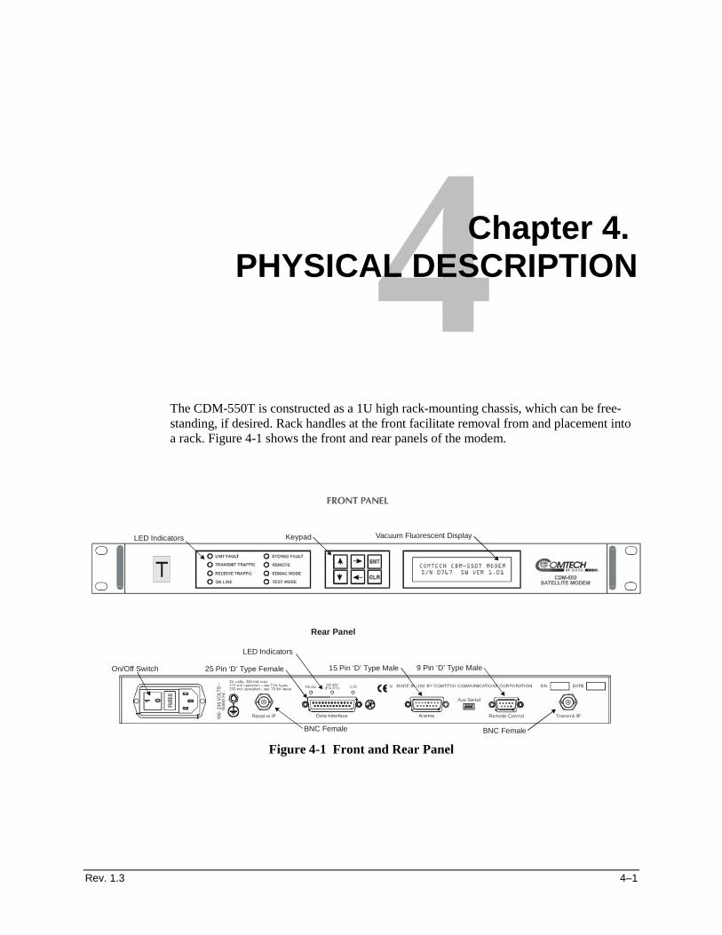
The CDM-550T is constructed as a 1U high rack-mounting chassis, which can be free-standing, if desired. Rack handles at the front facilitate removal from and placement into a rack. Figure 4-1 shows the front and rear panels of the modem.
Figure 4-1 Front and Rear Panel
Vacuum Fluorescent DisplayKeypadLED Indicators
On/Off Switch
LED Indicators
Rear Panel
25 Pin ‘D’ Type Female 15 Pin ‘D’ Type Male 9 Pin ‘D’ Type Male
BNC FemaleBNC Female
Physical Description CDM-550T Satellite Modem
4–2 Rev. 1.3
4.1 Front Panel
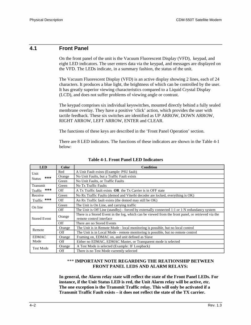
On the front panel of the unit is the Vacuum Fluorescent Display (VFD), keypad, and eight LED indicators. The user enters data via the keypad, and messages are displayed on the VFD. The LEDs indicate, in a summary fashion, the status of the unit. The Vacuum Fluorescent Display (VFD) is an active display showing 2 lines, each of 24 characters. It produces a blue light, the brightness of which can be controlled by the user. It has greatly superior viewing characteristics compared to a Liquid Crystal Display (LCD), and does not suffer problems of viewing angle or contrast. The keypad comprises six individual keyswitches, mounted directly behind a fully sealed membrane overlay. They have a positive ‘click’ action, which provides the user with tactile feedback. These six switches are identified as UP ARROW, DOWN ARROW, RIGHT ARROW, LEFT ARROW, ENTER and CLEAR. The functions of these keys are described in the ‘Front Panel Operation’ section. There are 8 LED indicators. The functions of these indicators are shown in the Table 4-1 below:
Table 4-1. Front Panel LED Indicators LED Color Condition
Red A Unit Fault exists (Example: PSU fault) Orange No Unit Faults, but a Traffic Fault exists
Unit Status *** Green No Unit Faults, or Traffic Faults
Green No Tx Traffic Faults Transmit Traffic *** Off A Tx Traffic fault exists OR the Tx Carrier is in OFF state
Green No Rx Traffic Faults (demod and Viterbi decoder are locked, everything is OK) Receive Traffic *** Off An Rx Traffic fault exists (the demod may still be OK)
Green The Unit is On Line, and carrying traffic On line Off The Unit is Off Line (standby) - forced by externally connected 1:1 or 1:N redundancy system
Orange There is a Stored Event in the log, which can be viewed from the front panel, or retrieved via the remote control interface Stored Event
Off There are no Stored Events Orange The Unit is in Remote Mode - local monitoring is possible, but no local control Remote Off The Unit is in Local Mode - remote monitoring is possible, but no remote control Orange Framing on, EDMAC on, and unit defined as Slave EDMAC
Mode Off Either no EDMAC, EDMAC Master, or Transparent mode is selected Orange A Test Mode is selected (Example: IF Loopback) Test Mode Off There is no Test Mode currently selected
*** IMPORTANT NOTE REGARDING THE REATIONSHIP BETWEEN FRONT PANEL LEDS AND ALARM RELAYS:
In general, the Alarm relay state will reflect the state of the Front Panel LEDs. For instance, if the Unit Status LED is red, the Unit Alarm relay will be active, etc. The one exception is the Transmit Traffic relay. This will only be activated if a Transmit Traffic Fault exists – it does not reflect the state of the TX carrier.
CDM-550T Satellite Modem Physical Description
Rev. 1.3 4–3
Rear Panel
External cables are attached to connectors on the rear panel of the CDM-550T. These comprise the IEC line input connector, the Receive and Transmit IF connectors, the Data connector, Alarms connector, Remote Control connector, and Auxiliary Serial connector. The IEC line input connector contains the ON/OFF switch for the unit. It is also fitted with two fuses - one each for line and neutral connections (or L1, L2, where appropriate). These are contained within the body of the connector, behind a small plastic flap. • For 230 volt AC operation, use T0.5A, (slow-blow) 20mm fuses. • For 115 volt AC operation, use T1A fuses, (slow-blow) 20mm fuses. FOR CONTINUED OPERATOR SAFETY, ALWAYS REPLACE THE FUSES WITH THE CORRECT TYPE AND RATING. The IF port connectors are both a 50 ohm BNC female type. 75 ohm cable connectors (male) will have no problem mating with this 50 ohm type. The Data connector is a 25 pin ‘D’ type female (DB25-F). This connector conforms to the EIA 530 pinout, which allows for connection of different electrical standards, including RS422, V.35, and RS232. Please note that it is the responsibility of the user to provide the appropriate cables to connect to this EIA 530 connector. A shielded 25 pin ‘D’ type provides a very solid solution to EMC problems, unlike the sometimes used V.35 Winchester connector. The pinout for the EIA 530 connector is provided in the next section. Note that the currently selected interface type is indicated by a small orange LED which is located immediately above the connector. This provides an easy visual indication to anyone mating a connector at the rear of the unit. The Alarms connector is a 15 pin 'D' type male (DB15-M). This provides the user with access to the Form-C relay contacts which indicate the fault status of the unit. These are typically connected to an external fault monitoring system, often found in satellite earth stations. In addition, the receive I and Q demodulator samples are provided on this connector. Connecting these signals to an oscilloscope in X,Y mode will provide the receive signal constellation diagram, which is a useful diagnostic aid. A pin is also provided which can mute the transmit carrier. This requires that the pin be shorted to ground, or a TTL ‘low’, or an RS232 ‘high’ signal be applied. As an aid to antenna pointing, or for driving step-track equipment, an analog AGC signal is provided on a pin of this connector. The demodulator incorporates three separate AGC control loops, one of which is analog, and two of which are entirely digital. The first of these loops keeps the signal level constant at the input to the flash A/D converter in the final IF stage. This loop has a limited dynamic range (~ 35 dB) and operates on the total power within the IF bandwidth (which varies with data rate). The characteristics of this control voltage are shown at the rear of the specifications section.
Physical Description CDM-550T Satellite Modem
4–4 Rev. 1.3
The pinout details for this connector are provided in the next section. The Remote Control connector is a 9 pin 'D' type female (DB9-M). Access is provided to remote control ports of the modem, both RS232 and RS485. The pinout details for this connector are provided in the next section. The Auxiliary Serial connector is an HE1402 3 pin header. A suitable mate for this connector is AMP part number 281838-3, with three crimp pins, AMP part number 182734-2, also required. This is an additional EIA232 serial port, which is only used when the modem is part of a 1:1 pair, at the distant-end of a link, and when both units are defined as EDMAC slaves. The pinout details for this connector are provided in the next section.
Rev. 1.3 5–1
5Chapter 5. CONNECTOR PINOUTS
5.1 Data Connector - 25 Pin ‘D’ Type Female
Table 5-1 Data Connector - 25 Pin ‘D’ Type Female Pin Generic Signal description Direction EIA-422/
EIA 530 V.35 EIA-232 Circuit
No 1 Shield - Shield FG AN 101 2 Transmit Data A DTE to Modem SD A SD A BA 103 3 Receive Data A Modem to DTE RD A RD A BB 104 7 Signal Ground - SG SG AB 102 8 Receiver Ready A Modem to DTE RR A RLSD * CF 109 9 Receive Clock B Modem to DTE RT B SCR B - 115
10 Receiver Ready B Modem to DTE RR B - - 109 11 Transmit Clock B DTE to Modem TT B SCTE B - 113 12 Internal Transmit Clock B Modem to DTE ST B SCT B - 114 14 Transmit Data B DTE to Modem SD B SD B - 103 15 Internal Transmit Clock A Modem to DTE ST A SCT A DB 114 16 Receive Data B Modem to DTE RD B RD B - 104 17 Receive Clock A Modem to DTE RT A SCR A DD 115 23 External Carrier Off
(EIA-232 ‘1' or TTL ‘low’ ) DTE to Modem - - - -
24 Transmit Clock A DTE to Modem TT A SCTE A DA 113 NOTES: • Receiver ready is an EIA-232-level control signal on a V.35 interface • DO NOT connect signals to pins which are not shown - these pins are reserved for use by the redundancy system • ‘B’ signal lines are not used for EIA-232 applications • For X.21 operation, use the EIA-422 pins, but ignore Receive Clock if the Modem is DTE, and ignore Transmit clocks if the
Modem is DCE
Connector Pinouts CDM-550T Satellite Modem
5–2 Rev. 1.3
5.2 Alarms Connector - 15 Pin ‘D’ Type Male
Table 5-2 Alarms Connector - 15 Pin ‘D’ Type Male
Pin Description 1 Ground 2 Receive AGC voltage 3 Receive Q sample (for constellation display) 4 Unit Fault Relay - Common 5 Unit Fault Relay - Normally Open 6 Transmit Traffic Relay - Normally Closed 7 Receive Traffic Relay - Common 8 Receive Traffic Relay - Normally Open 9 External Carrier Off input
10 ---- No Connection ---- 11 Receive I sample (for constellation display) 12 Unit Fault Relay - Normally Closed 13 Transmit Traffic Relay - Common 14 Transmit Traffic Relay - Normally Open 15 Receive Traffic Relay - Normally Closed
Note: ‘Normally Open’ refers to the NON-FAIL state
5.3 Remote Control Connector - 9 Pin ‘D’ Type Male
Table 5-3 Remote Control Connector -
9 Pin ‘D’ Type Male Pin Description 1 Ground 2 EIA-232 Transmit Data (Out) 3 EIA-232 Receive Data (In) 4 Reserved - do not connect to this pin 5 Ground 6 EIA-485 Receive Data B (In) 7 EIA-485 Receive Data A (In) 8 EIA-485 Transmit Data B (Out) 9 EIA-485 Transmit Data A (Out)
CDM-550T Satellite Modem Connector Pinouts
Rev. 1.3 5–3
5.4 Auxiliary Serial Connector - HE1402 3 Pin Header
Table 5-4 Auxiliary Serial Connector -
HE1402 3 Pin Header
Pin Description
1 EIA-232 Transmit Data (Output)
2 Ground
3 EIA-232 Receive Data (Input)
PIN NUMBERING: Looking at the rear panel, pin 1 is on the right-hand side :
•••• •••• •••• Pin 1

Connector Pinouts CDM-550T Satellite Modem
5–4 Rev. 1.3
This page is intentionally blank.
Rev. 1.3 6–1
6Chapter 6. FRONT PANEL OPERATION
6.1 Description
The user can fully control and monitor the operation of the CDM-550T from the front panel, using the keypad and display. Nested menus are used, which display all available options, and prompt the user to carry out a required action. The display has two lines each of 24 characters. On most menu screens, the user will observe a flashing solid block cursor, which blinks at a once-per-second rate. This indicates the currently selected item, digit, or field. Where this solid block cursor would obscure the item being edited (for example, a numeric field) the cursor will automatically change to an underline cursor. If the user were to display the same screen for weeks at a time, the display could become ‘burnt’ with this image. To prevent this, the unit has a ‘screen saver’ feature which will activate after 1 hour. The top line of the display will show the Circuit ID (which can be entered by the user) and the bottom line will show the circuit Eb/No value (if the demod is locked) followed by ‘Press any key....’. The message moves from right to left across the screen, then wraps around. Pressing any key will restore the previous screen.
Front Panel Operation CDM-550T Satellite Modem
6–2 Rev. 1.3
The keypad has six keys, the functions of which are described below: RIGHT ARROW Moves the cursor to the right, when it is displayed
LEFT ARROW Moves the cursor to the left, when it is displayed
UP ARROW Used for editing the value at the current cursor position, if appropriate. If this is a
numeric field, this will increment the value.
DOWN ARROW Used for editing the value at the current cursor position, if appropriate. If this is a numeric field, this will decrement the value.
ENTER (ENT) Used to accept an edited entry. Most menus prompt the user to press this key, by displaying the text (PRESS ENTER), (ENTER) or (ENT). This results in the entry being accepted, and the user is then returned to the previous menu.
CLEAR (CLR) Used to escape from the current operation and return to the previous menu. IMPORTANT NOTE:
The keypad has an auto-repeat feature. If a key is held down for more than 1 second, the key action will repeat, automatically, at the rate of 15 keystrokes per second. This is particularly useful when editing numeric fields, with many digits, such as frequency or data rate.
6.2 Menu Trees
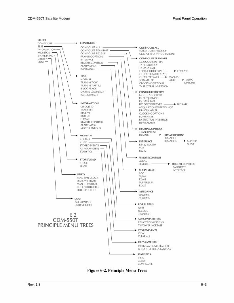
Figure 6-2 shows the menu structure of the CDM-550T. The detailed screens and menus will now be described. Note: The ‘level’ of the menu (how far down into the structure) is indicated by how far
the screen is indented from the left.
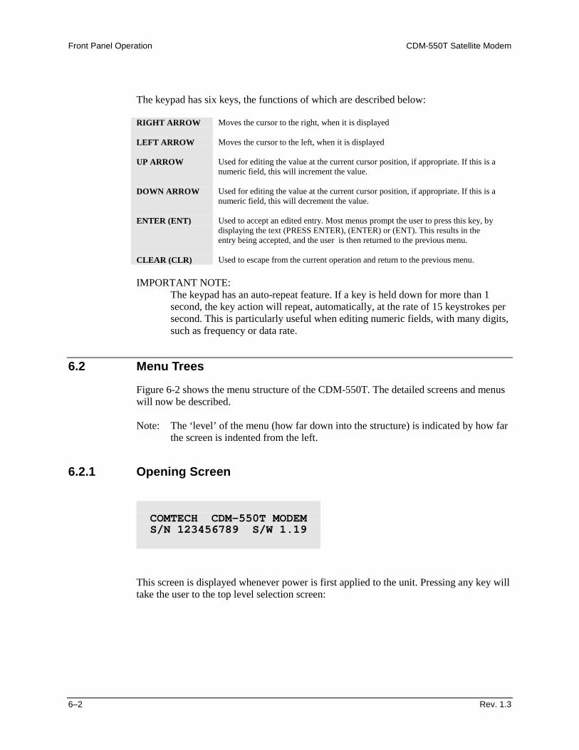
6.2.1 Opening Screen
This screen is displayed whenever power is first applied to the unit. Pressing any key will take the user to the top level selection screen:
COMTECH CDM-550T MODEM S/N 123456789 S/W 1.19
CDM-550T Satellite Modem Front Panel Operation
Rev. 1.3 6–3
Figure 6-2. Principle Menu Trees
Front Panel Operation CDM-550T Satellite Modem
6–4 Rev. 1.3
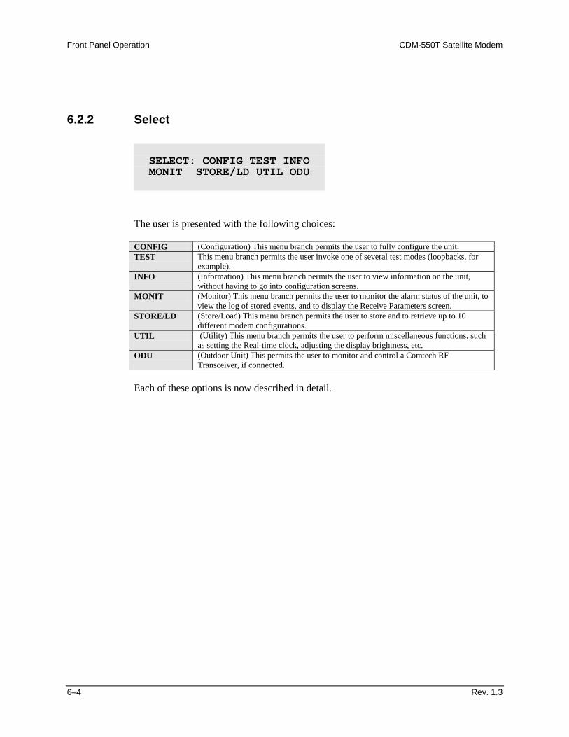
6.2.2 Select
The user is presented with the following choices: CONFIG (Configuration) This menu branch permits the user to fully configure the unit. TEST This menu branch permits the user invoke one of several test modes (loopbacks, for
example). INFO (Information) This menu branch permits the user to view information on the unit,
without having to go into configuration screens. MONIT (Monitor) This menu branch permits the user to monitor the alarm status of the unit, to
view the log of stored events, and to display the Receive Parameters screen. STORE/LD (Store/Load) This menu branch permits the user to store and to retrieve up to 10
different modem configurations. UTIL (Utility) This menu branch permits the user to perform miscellaneous functions, such
as setting the Real-time clock, adjusting the display brightness, etc. ODU (Outdoor Unit) This permits the user to monitor and control a Comtech RF
Transceiver, if connected. Each of these options is now described in detail.
SELECT: CONFIG TEST INFO MONIT STORE/LD UTIL ODU
CDM-550T Satellite Modem Front Panel Operation
Rev. 1.3 6–5
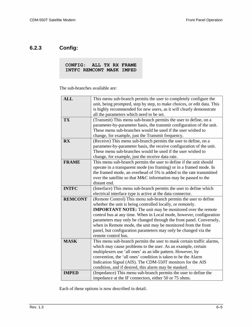
6.2.3 Config:
The sub-branches available are:
ALL This menu sub-branch permits the user to completely configure the unit, being prompted, step by step, to make choices, or edit data. This is highly recommended for new users, as it will clearly demonstrate all the parameters which need to be set.
TX (Transmit) This menu sub-branch permits the user to define, on a parameter-by-parameter basis, the transmit configuration of the unit. These menu sub-branches would be used if the user wished to change, for example, just the Transmit frequency.
RX (Receive) This menu sub-branch permits the user to define, on a parameter-by-parameter basis, the receive configuration of the unit. These menu sub-branches would be used if the user wished to change, for example, just the receive data rate.
FRAME This menu sub-branch permits the user to define if the unit should operate in a transparent mode (no framing) or in a framed mode. In the framed mode, an overhead of 5% is added to the rate transmitted over the satellite so that M&C information may be passed to the distant end.
INTFC (Interface) This menu sub-branch permits the user to define which electrical interface type is active at the data connector.
REMCONT (Remote Control) This menu sub-branch permits the user to define whether the unit is being controlled locally, or remotely. IMPORTANT NOTE: The unit may be monitored over the remote control bus at any time. When in Local mode, however, configuration parameters may only be changed through the front panel. Conversely, when in Remote mode, the unit may be monitored from the front panel, but configuration parameters may only be changed via the remote control bus.
MASK This menu sub-branch permits the user to mask certain traffic alarms, which may cause problems to the user. As an example, certain multiplexers use ‘all ones’ as an idle pattern. However, by convention, the ‘all ones’ condition is taken to be the Alarm Indication Signal (AIS). The CDM-550T monitors for the AIS condition, and if desired, this alarm may be masked.
IMPED (Impedance) This menu sub-branch permits the user to define the impedance at the IF connectors, either 50 or 75 ohms.
Each of these options is now described in detail.
CONFIG: ALL TX RX FRAME INTFC REMCONT MASK IMPED
Front Panel Operation CDM-550T Satellite Modem
6–6 Rev. 1.3
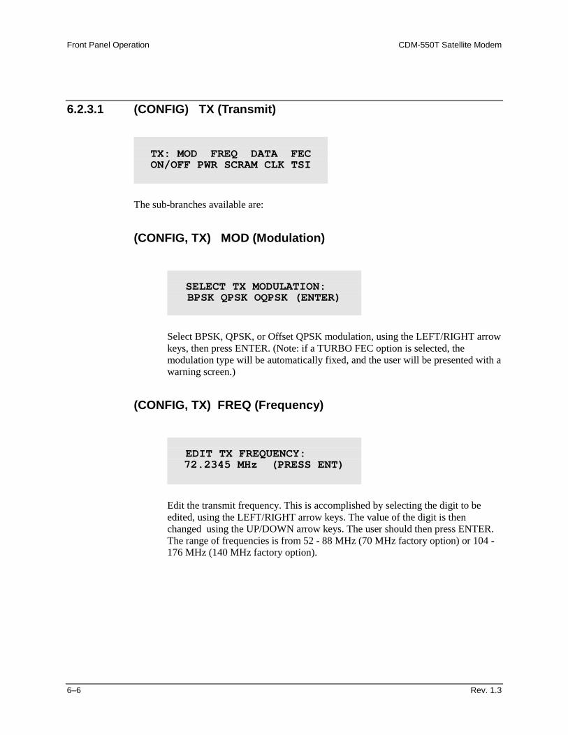
6.2.3.1 (CONFIG) TX (Transmit)
The sub-branches available are:
(CONFIG, TX) MOD (Modulation)
Select BPSK, QPSK, or Offset QPSK modulation, using the LEFT/RIGHT arrow keys, then press ENTER. (Note: if a TURBO FEC option is selected, the modulation type will be automatically fixed, and the user will be presented with a warning screen.)
(CONFIG, TX) FREQ (Frequency)
Edit the transmit frequency. This is accomplished by selecting the digit to be edited, using the LEFT/RIGHT arrow keys. The value of the digit is then changed using the UP/DOWN arrow keys. The user should then press ENTER. The range of frequencies is from 52 - 88 MHz (70 MHz factory option) or 104 - 176 MHz (140 MHz factory option).
TX: MOD FREQ DATA FEC ON/OFF PWR SCRAM CLK TSI
SELECT TX MODULATION:
BPSK QPSK OQPSK (ENTER)
EDIT TX FREQUENCY:
72.2345 MHz (PRESS ENT)
CDM-550T Satellite Modem Front Panel Operation
Rev. 1.3 6–7
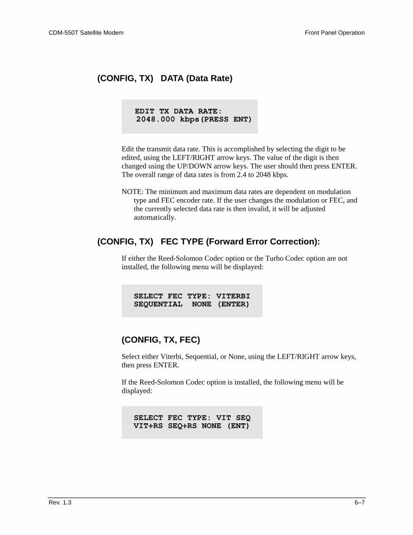
(CONFIG, TX) DATA (Data Rate)
Edit the transmit data rate. This is accomplished by selecting the digit to be edited, using the LEFT/RIGHT arrow keys. The value of the digit is then changed using the UP/DOWN arrow keys. The user should then press ENTER. The overall range of data rates is from 2.4 to 2048 kbps. NOTE: The minimum and maximum data rates are dependent on modulation
type and FEC encoder rate. If the user changes the modulation or FEC, and the currently selected data rate is then invalid, it will be adjusted automatically.
(CONFIG, TX) FEC TYPE (Forward Error Correction):
If either the Reed-Solomon Codec option or the Turbo Codec option are not installed, the following menu will be displayed:
(CONFIG, TX, FEC)
Select either Viterbi, Sequential, or None, using the LEFT/RIGHT arrow keys, then press ENTER. If the Reed-Solomon Codec option is installed, the following menu will be displayed:
EDIT TX DATA RATE: 2048.000 kbps(PRESS ENT)
SELECT FEC TYPE: VITERBI SEQUENTIAL NONE (ENTER)
SELECT FEC TYPE: VIT SEQ VIT+RS SEQ+RS NONE (ENT)
Front Panel Operation CDM-550T Satellite Modem
6–8 Rev. 1.3
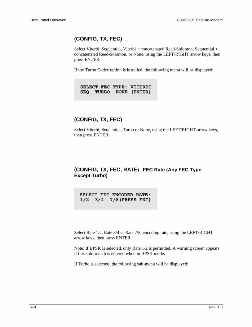
(CONFIG, TX, FEC)
Select Viterbi, Sequential, Viterbi + concatenated Reed-Solomon, Sequential + concatenated Reed-Solomon, or None, using the LEFT/RIGHT arrow keys, then press ENTER. If the Turbo Codec option is installed, the following menu will be displayed:
(CONFIG, TX, FEC)
Select Viterbi, Sequential, Turbo or None, using the LEFT/RIGHT arrow keys, then press ENTER.
(CONFIG, TX, FEC, RATE) FEC Rate (Any FEC Type Except Turbo)
Select Rate 1/2, Rate 3/4 or Rate 7/8 encoding rate, using the LEFT/RIGHT arrow keys, then press ENTER. Note: If BPSK is selected, only Rate 1/2 is permitted. A warning screen appears if this sub-branch is entered when in BPSK mode. If Turbo is selected, the following sub-menu will be displayed:
SELECT FEC TYPE: VITERBI SEQ TURBO NONE (ENTER)
SELECT FEC ENCODER RATE: 1/2 3/4 7/8(PRESS ENT)
CDM-550T Satellite Modem Front Panel Operation
Rev. 1.3 6–9
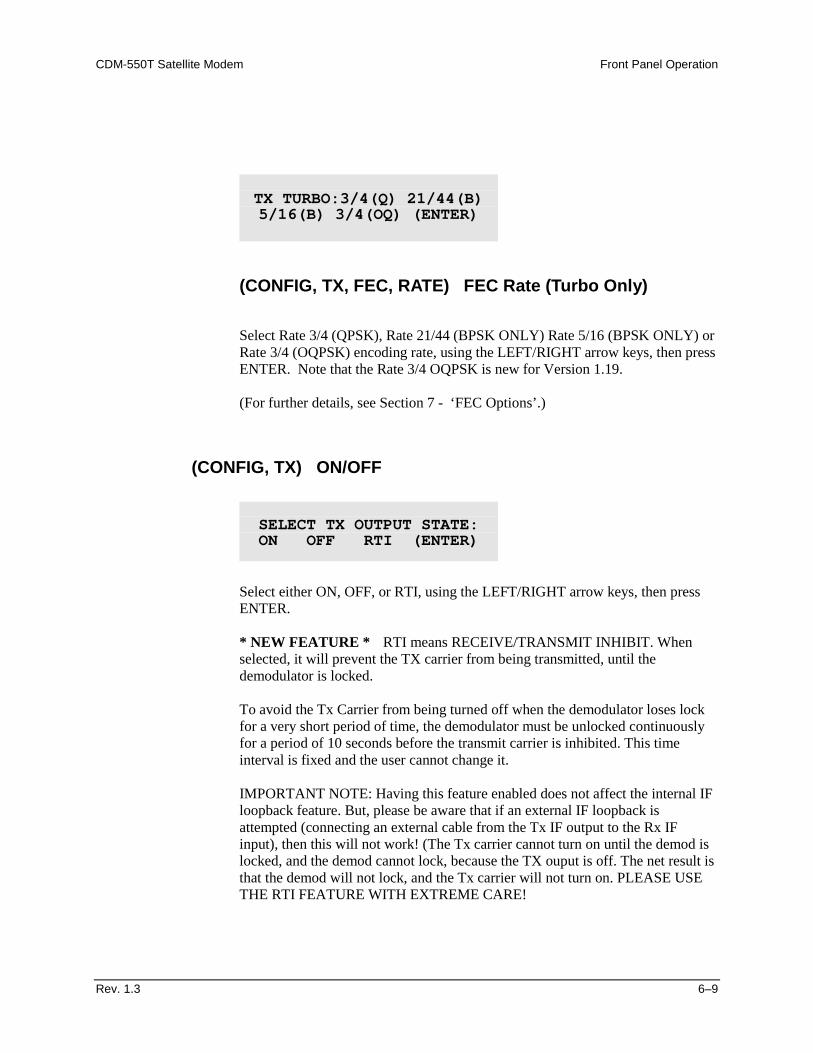
(CONFIG, TX, FEC, RATE) FEC Rate (Turbo Only)
Select Rate 3/4 (QPSK), Rate 21/44 (BPSK ONLY) Rate 5/16 (BPSK ONLY) or Rate 3/4 (OQPSK) encoding rate, using the LEFT/RIGHT arrow keys, then press ENTER. Note that the Rate 3/4 OQPSK is new for Version 1.19. (For further details, see Section 7 - ‘FEC Options’.)
(CONFIG, TX) ON/OFF
Select either ON, OFF, or RTI, using the LEFT/RIGHT arrow keys, then press ENTER. * NEW FEATURE * RTI means RECEIVE/TRANSMIT INHIBIT. When selected, it will prevent the TX carrier from being transmitted, until the demodulator is locked.
To avoid the Tx Carrier from being turned off when the demodulator loses lock for a very short period of time, the demodulator must be unlocked continuously for a period of 10 seconds before the transmit carrier is inhibited. This time interval is fixed and the user cannot change it. IMPORTANT NOTE: Having this feature enabled does not affect the internal IF loopback feature. But, please be aware that if an external IF loopback is attempted (connecting an external cable from the Tx IF output to the Rx IF input), then this will not work! (The Tx carrier cannot turn on until the demod is locked, and the demod cannot lock, because the TX ouput is off. The net result is that the demod will not lock, and the Tx carrier will not turn on. PLEASE USE THE RTI FEATURE WITH EXTREME CARE!
TX TURBO:3/4(Q) 21/44(B) 5/16(B) 3/4(OQ) (ENTER)
SELECT TX OUTPUT STATE: ON OFF RTI (ENTER)
Front Panel Operation CDM-550T Satellite Modem
6–10 Rev. 1.3
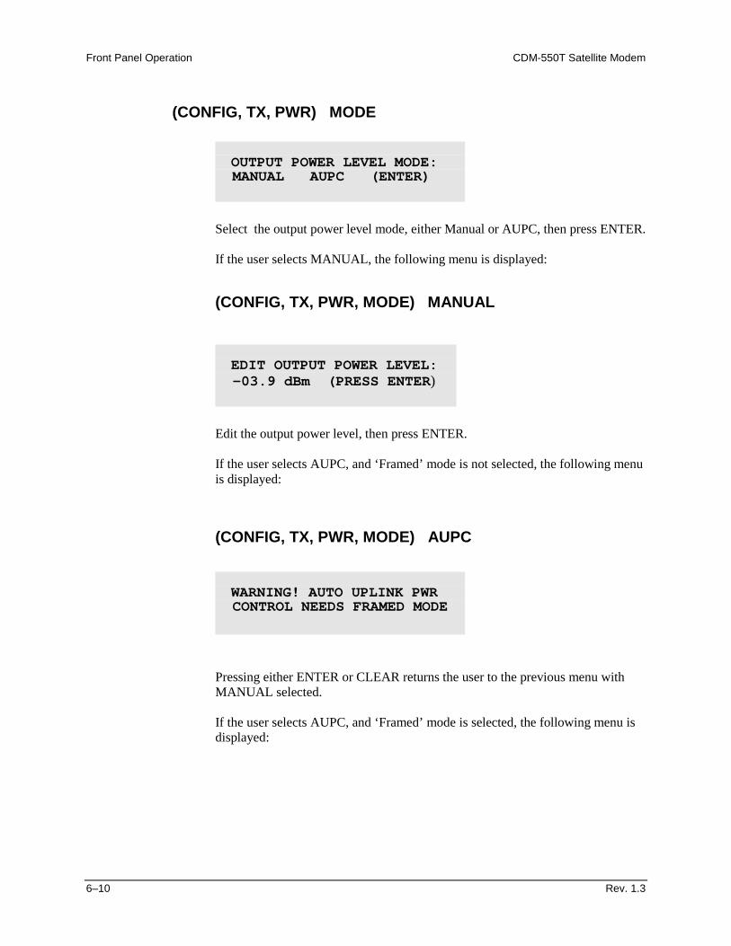
(CONFIG, TX, PWR) MODE
Select the output power level mode, either Manual or AUPC, then press ENTER. If the user selects MANUAL, the following menu is displayed:
(CONFIG, TX, PWR, MODE) MANUAL
Edit the output power level, then press ENTER. If the user selects AUPC, and ‘Framed’ mode is not selected, the following menu is displayed:
(CONFIG, TX, PWR, MODE) AUPC
Pressing either ENTER or CLEAR returns the user to the previous menu with MANUAL selected. If the user selects AUPC, and ‘Framed’ mode is selected, the following menu is displayed:
OUTPUT POWER LEVEL MODE: MANUAL AUPC (ENTER)
EDIT OUTPUT POWER LEVEL: -03.9 dBm (PRESS ENTER)
WARNING! AUTO UPLINK PWR CONTROL NEEDS FRAMED MODE
CDM-550T Satellite Modem Front Panel Operation
Rev. 1.3 6–11
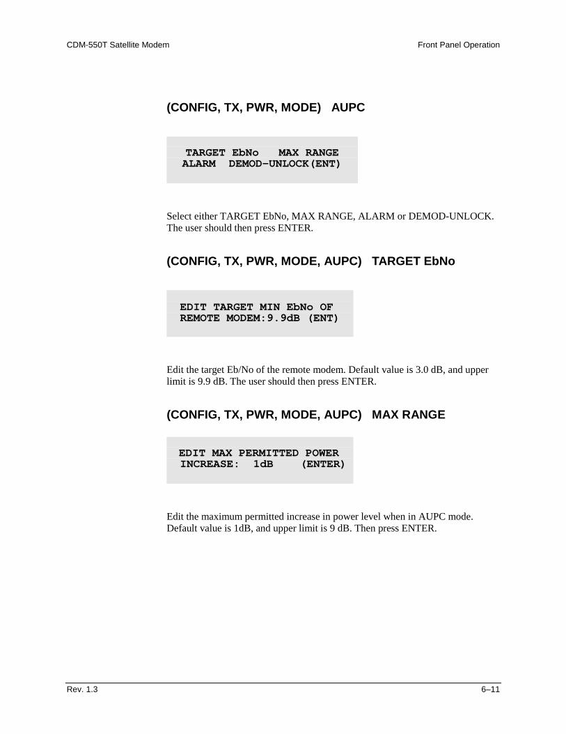
(CONFIG, TX, PWR, MODE) AUPC
Select either TARGET EbNo, MAX RANGE, ALARM or DEMOD-UNLOCK. The user should then press ENTER.
(CONFIG, TX, PWR, MODE, AUPC) TARGET EbNo
Edit the target Eb/No of the remote modem. Default value is 3.0 dB, and upper limit is 9.9 dB. The user should then press ENTER.
(CONFIG, TX, PWR, MODE, AUPC) MAX RANGE
Edit the maximum permitted increase in power level when in AUPC mode. Default value is 1dB, and upper limit is 9 dB. Then press ENTER.
TARGET EbNo MAX RANGE ALARM DEMOD-UNLOCK(ENT)
EDIT TARGET MIN EbNo OF REMOTE MODEM:9.9dB (ENT)
EDIT MAX PERMITTED POWER INCREASE: 1dB (ENTER)
Front Panel Operation CDM-550T Satellite Modem
6–12 Rev. 1.3
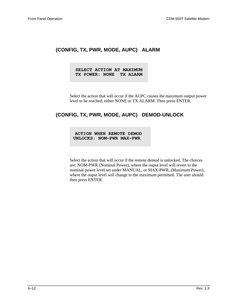
(CONFIG, TX, PWR, MODE, AUPC) ALARM
Select the action that will occur if the AUPC causes the maximum output power level to be reached, either NONE or TX ALARM. Then press ENTER.
(CONFIG, TX, PWR, MODE, AUPC) DEMOD-UNLOCK
Select the action that will occur if the remote demod is unlocked. The choices are: NOM-PWR (Nominal Power), where the ouput level will revert to the nominal power level set under MANUAL, or MAX-PWR, (Maximum Power), where the ouput level will change to the maximum permitted. The user should then press ENTER.
SELECT ACTION AT MAXIMUM TX POWER: NONE TX ALARM
ACTION WHEN REMOTE DEMOD UNLOCKS: NOM-PWR MAX-PWR
CDM-550T Satellite Modem Front Panel Operation
Rev. 1.3 6–13
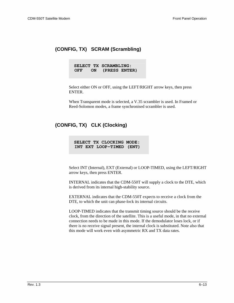
(CONFIG, TX) SCRAM (Scrambling)
Select either ON or OFF, using the LEFT/RIGHT arrow keys, then press ENTER. When Transparent mode is selected, a V.35 scrambler is used. In Framed or Reed-Solomon modes, a frame synchronised scrambler is used.
(CONFIG, TX) CLK (Clocking)
Select INT (Internal), EXT (External) or LOOP-TIMED, using the LEFT/RIGHT arrow keys, then press ENTER. INTERNAL indicates that the CDM-550T will supply a clock to the DTE, which is derived from its internal high-stability source. EXTERNAL indicates that the CDM-550T expects to receive a clock from the DTE, to which the unit can phase-lock its internal circuits. LOOP-TIMED indicates that the transmit timing source should be the receive clock, from the direction of the satellite. This is a useful mode, in that no external connection needs to be made in this mode. If the demodulator loses lock, or if there is no receive signal present, the internal clock is substituted. Note also that this mode will work even with asymmetric RX and TX data rates.
SELECT TX SCRAMBLING: OFF ON (PRESS ENTER)
SELECT TX CLOCKING MODE: INT EXT LOOP-TIMED (ENT)
Front Panel Operation CDM-550T Satellite Modem
6–14 Rev. 1.3
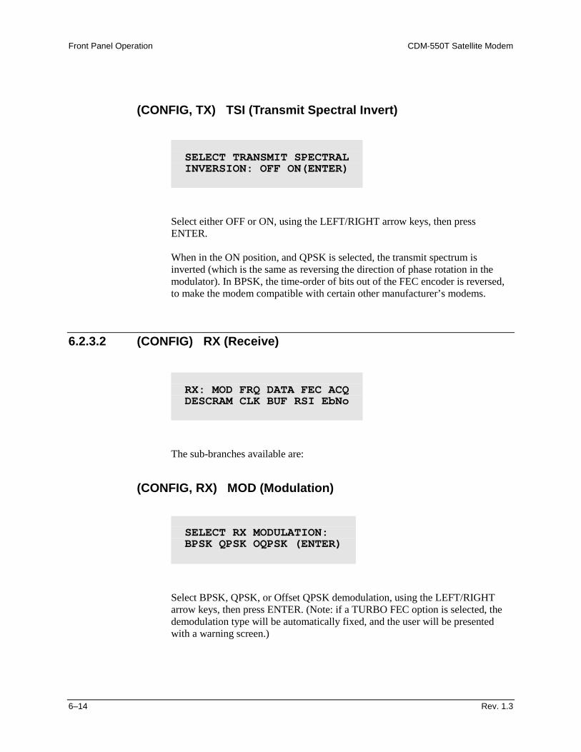
(CONFIG, TX) TSI (Transmit Spectral Invert)
Select either OFF or ON, using the LEFT/RIGHT arrow keys, then press ENTER. When in the ON position, and QPSK is selected, the transmit spectrum is inverted (which is the same as reversing the direction of phase rotation in the modulator). In BPSK, the time-order of bits out of the FEC encoder is reversed, to make the modem compatible with certain other manufacturer’s modems.
6.2.3.2 (CONFIG) RX (Receive)
The sub-branches available are:
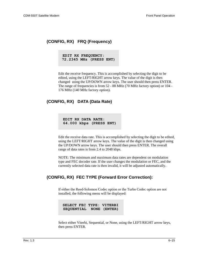
(CONFIG, RX) MOD (Modulation)
Select BPSK, QPSK, or Offset QPSK demodulation, using the LEFT/RIGHT arrow keys, then press ENTER. (Note: if a TURBO FEC option is selected, the demodulation type will be automatically fixed, and the user will be presented with a warning screen.)
SELECT TRANSMIT SPECTRAL INVERSION: OFF ON(ENTER)
RX: MOD FRQ DATA FEC ACQ DESCRAM CLK BUF RSI EbNo
SELECT RX MODULATION: BPSK QPSK OQPSK (ENTER)
CDM-550T Satellite Modem Front Panel Operation
Rev. 1.3 6–15
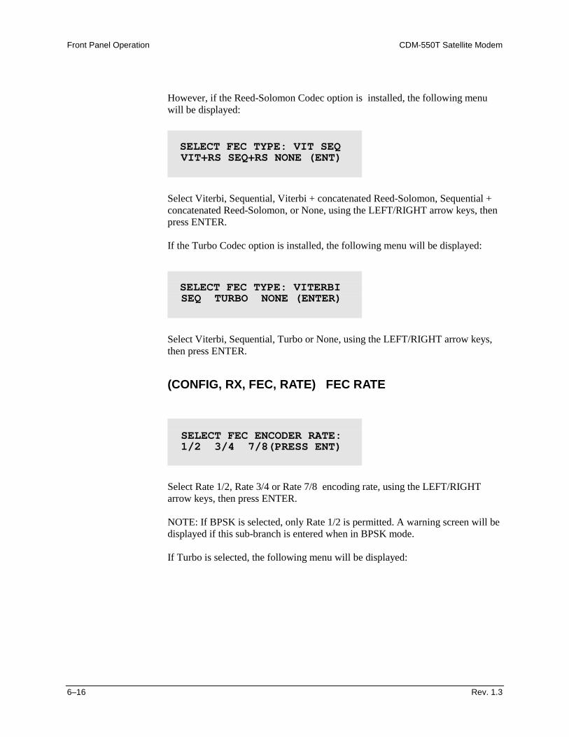
(CONFIG, RX) FRQ (Frequency)
Edit the receive frequency. This is accomplished by selecting the digit to be edited, using the LEFT/RIGHT arrow keys. The value of the digit is then changed using the UP/DOWN arrow keys. The user should then press ENTER. The range of frequencies is from 52 - 88 MHz (70 MHz factory option) or 104 - 176 MHz (140 MHz factory option).
(CONFIG, RX) DATA (Data Rate)
Edit the receive data rate. This is accomplished by selecting the digit to be edited, using the LEFT/RIGHT arrow keys. The value of the digit is then changed using the UP/DOWN arrow keys. The user should then press ENTER. The overall range of data rates is from 2.4 to 2048 kbps. NOTE: The minimum and maximum data rates are dependent on modulation type and FEC decoder rate. If the user changes the modulation or FEC, and the currently selected data rate is then invalid, it will be adjusted automatically.
(CONFIG, RX) FEC TYPE (Forward Error Correction):
If either the Reed-Solomon Codec option or the Turbo Codec option are not installed, the following menu will be displayed:
Select either Viterbi, Sequential, or None, using the LEFT/RIGHT arrow keys, then press ENTER.
EDIT RX FREQUENCY: 72.2345 MHz (PRESS ENT)
EDIT RX DATA RATE: 64.000 kbps (PRESS ENT)
SELECT FEC TYPE: VITERBI SEQUENTIAL NONE (ENTER)
Front Panel Operation CDM-550T Satellite Modem
6–16 Rev. 1.3
However, if the Reed-Solomon Codec option is installed, the following menu will be displayed:
Select Viterbi, Sequential, Viterbi + concatenated Reed-Solomon, Sequential + concatenated Reed-Solomon, or None, using the LEFT/RIGHT arrow keys, then press ENTER. If the Turbo Codec option is installed, the following menu will be displayed:
Select Viterbi, Sequential, Turbo or None, using the LEFT/RIGHT arrow keys, then press ENTER.
(CONFIG, RX, FEC, RATE) FEC RATE
Select Rate 1/2, Rate 3/4 or Rate 7/8 encoding rate, using the LEFT/RIGHT arrow keys, then press ENTER. NOTE: If BPSK is selected, only Rate 1/2 is permitted. A warning screen will be displayed if this sub-branch is entered when in BPSK mode. If Turbo is selected, the following menu will be displayed:
SELECT FEC TYPE: VIT SEQ VIT+RS SEQ+RS NONE (ENT)
SELECT FEC TYPE: VITERBI SEQ TURBO NONE (ENTER)
SELECT FEC ENCODER RATE: 1/2 3/4 7/8(PRESS ENT)
CDM-550T Satellite Modem Front Panel Operation
Rev. 1.3 6–17
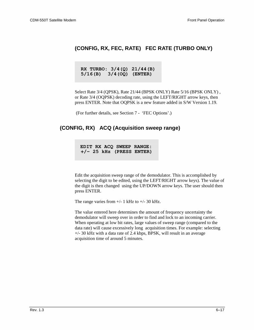
(CONFIG, RX, FEC, RATE) FEC RATE (TURBO ONLY)
Select Rate 3/4 (QPSK), Rate 21/44 (BPSK ONLY) Rate 5/16 (BPSK ONLY) , or Rate 3/4 (OQPSK) decoding rate, using the LEFT/RIGHT arrow keys, then press ENTER. Note that OQPSK is a new feature added in S/W Version 1.19. (For further details, see Section 7 - ‘FEC Options’.)
(CONFIG, RX) ACQ (Acquisition sweep range)
Edit the acquisition sweep range of the demodulator. This is accomplished by selecting the digit to be edited, using the LEFT/RIGHT arrow keys). The value of the digit is then changed using the UP/DOWN arrow keys. The user should then press ENTER. The range varies from +/- 1 kHz to +/- 30 kHz. The value entered here determines the amount of frequency uncertainty the demodulator will sweep over in order to find and lock to an incoming carrier. When operating at low bit rates, large values of sweep range (compared to the data rate) will cause excessively long acquisition times. For example: selecting +/- 30 kHz with a data rate of 2.4 kbps, BPSK, will result in an average acquisition time of around 5 minutes.
RX TURBO: 3/4(Q) 21/44(B) 5/16(B) 3/4(OQ) (ENTER)
EDIT RX ACQ SWEEP RANGE: +/- 25 kHz (PRESS ENTER)
Front Panel Operation CDM-550T Satellite Modem
6–18 Rev. 1.3
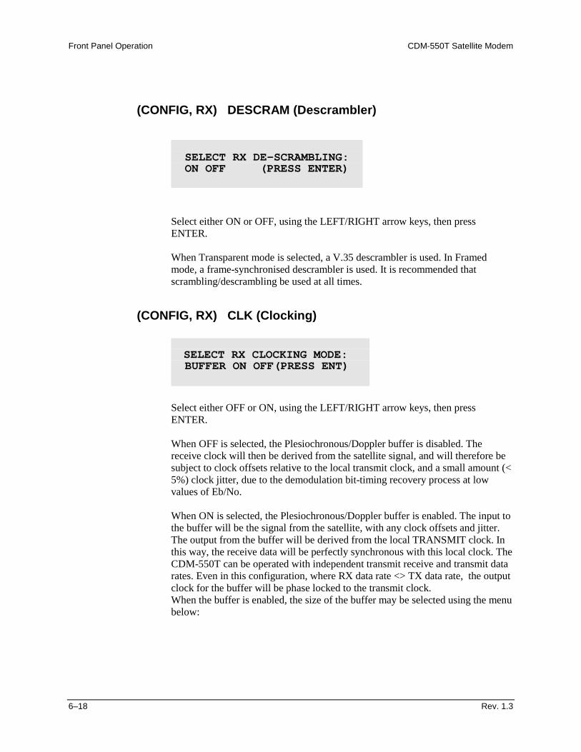
(CONFIG, RX) DESCRAM (Descrambler)
Select either ON or OFF, using the LEFT/RIGHT arrow keys, then press ENTER. When Transparent mode is selected, a V.35 descrambler is used. In Framed mode, a frame-synchronised descrambler is used. It is recommended that scrambling/descrambling be used at all times.
(CONFIG, RX) CLK (Clocking)
Select either OFF or ON, using the LEFT/RIGHT arrow keys, then press ENTER. When OFF is selected, the Plesiochronous/Doppler buffer is disabled. The receive clock will then be derived from the satellite signal, and will therefore be subject to clock offsets relative to the local transmit clock, and a small amount (< 5%) clock jitter, due to the demodulation bit-timing recovery process at low values of Eb/No. When ON is selected, the Plesiochronous/Doppler buffer is enabled. The input to the buffer will be the signal from the satellite, with any clock offsets and jitter. The output from the buffer will be derived from the local TRANSMIT clock. In this way, the receive data will be perfectly synchronous with this local clock. The CDM-550T can be operated with independent transmit receive and transmit data rates. Even in this configuration, where RX data rate <> TX data rate, the output clock for the buffer will be phase locked to the transmit clock. When the buffer is enabled, the size of the buffer may be selected using the menu below:
SELECT RX DE-SCRAMBLING: ON OFF (PRESS ENTER)
SELECT RX CLOCKING MODE: BUFFER ON OFF(PRESS ENT)
CDM-550T Satellite Modem Front Panel Operation
Rev. 1.3 6–19
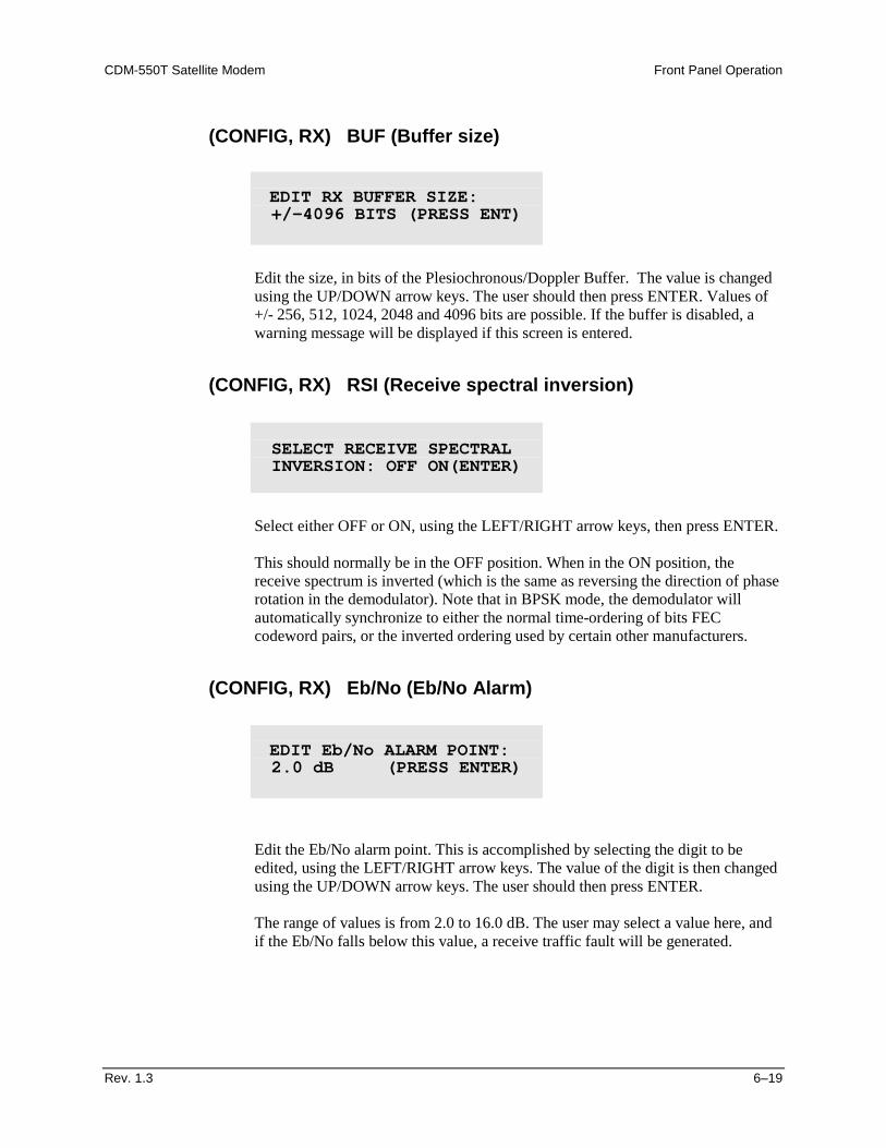
(CONFIG, RX) BUF (Buffer size)
Edit the size, in bits of the Plesiochronous/Doppler Buffer. The value is changed using the UP/DOWN arrow keys. The user should then press ENTER. Values of +/- 256, 512, 1024, 2048 and 4096 bits are possible. If the buffer is disabled, a warning message will be displayed if this screen is entered.
(CONFIG, RX) RSI (Receive spectral inversion)
Select either OFF or ON, using the LEFT/RIGHT arrow keys, then press ENTER. This should normally be in the OFF position. When in the ON position, the receive spectrum is inverted (which is the same as reversing the direction of phase rotation in the demodulator). Note that in BPSK mode, the demodulator will automatically synchronize to either the normal time-ordering of bits FEC codeword pairs, or the inverted ordering used by certain other manufacturers.
(CONFIG, RX) Eb/No (Eb/No Alarm)
Edit the Eb/No alarm point. This is accomplished by selecting the digit to be edited, using the LEFT/RIGHT arrow keys. The value of the digit is then changed using the UP/DOWN arrow keys. The user should then press ENTER.
The range of values is from 2.0 to 16.0 dB. The user may select a value here, and if the Eb/No falls below this value, a receive traffic fault will be generated.
EDIT RX BUFFER SIZE: +/-4096 BITS (PRESS ENT)
SELECT RECEIVE SPECTRAL INVERSION: OFF ON(ENTER)
EDIT Eb/No ALARM POINT: 2.0 dB (PRESS ENTER)
Front Panel Operation CDM-550T Satellite Modem
6–20 Rev. 1.3
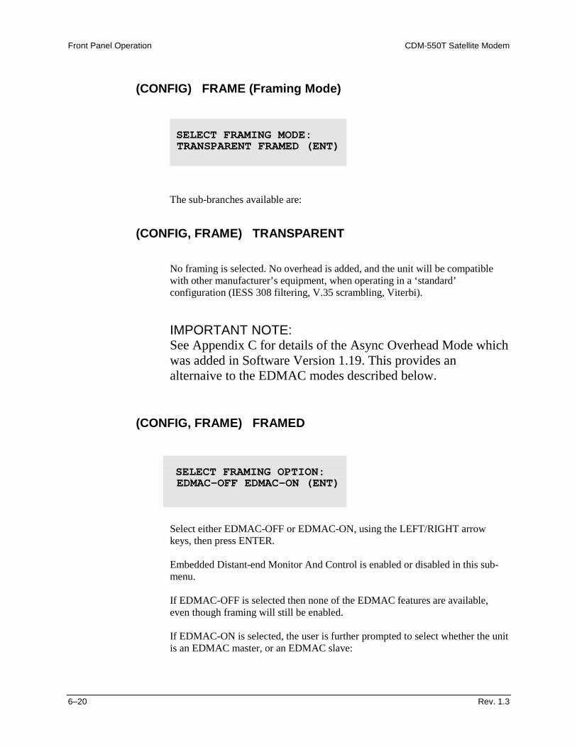
(CONFIG) FRAME (Framing Mode)
The sub-branches available are:
(CONFIG, FRAME) TRANSPARENT
No framing is selected. No overhead is added, and the unit will be compatible with other manufacturer’s equipment, when operating in a ‘standard’ configuration (IESS 308 filtering, V.35 scrambling, Viterbi). IMPORTANT NOTE: See Appendix C for details of the Async Overhead Mode which was added in Software Version 1.19. This provides an alternaive to the EDMAC modes described below.
(CONFIG, FRAME) FRAMED
Select either EDMAC-OFF or EDMAC-ON, using the LEFT/RIGHT arrow keys, then press ENTER. Embedded Distant-end Monitor And Control is enabled or disabled in this sub-menu. If EDMAC-OFF is selected then none of the EDMAC features are available, even though framing will still be enabled. If EDMAC-ON is selected, the user is further prompted to select whether the unit is an EDMAC master, or an EDMAC slave:
SELECT FRAMING MODE: TRANSPARENT FRAMED (ENT)
SELECT FRAMING OPTION: EDMAC-OFF EDMAC-ON (ENT)
CDM-550T Satellite Modem Front Panel Operation
Rev. 1.3 6–21
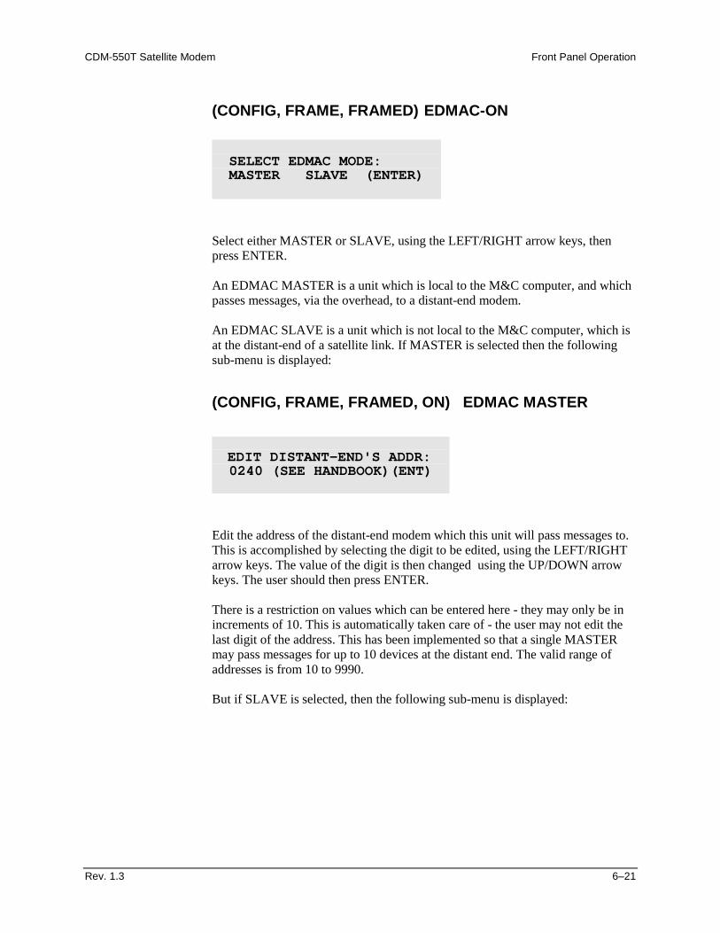
(CONFIG, FRAME, FRAMED) EDMAC-ON
Select either MASTER or SLAVE, using the LEFT/RIGHT arrow keys, then press ENTER. An EDMAC MASTER is a unit which is local to the M&C computer, and which passes messages, via the overhead, to a distant-end modem.
An EDMAC SLAVE is a unit which is not local to the M&C computer, which is at the distant-end of a satellite link. If MASTER is selected then the following sub-menu is displayed:
(CONFIG, FRAME, FRAMED, ON) EDMAC MASTER
Edit the address of the distant-end modem which this unit will pass messages to. This is accomplished by selecting the digit to be edited, using the LEFT/RIGHT arrow keys. The value of the digit is then changed using the UP/DOWN arrow keys. The user should then press ENTER. There is a restriction on values which can be entered here - they may only be in increments of 10. This is automatically taken care of - the user may not edit the last digit of the address. This has been implemented so that a single MASTER may pass messages for up to 10 devices at the distant end. The valid range of addresses is from 10 to 9990.
But if SLAVE is selected, then the following sub-menu is displayed:
SELECT EDMAC MODE: MASTER SLAVE (ENTER)
EDIT DISTANT-END'S ADDR: 0240 (SEE HANDBOOK)(ENT)
Front Panel Operation CDM-550T Satellite Modem
6–22 Rev. 1.3
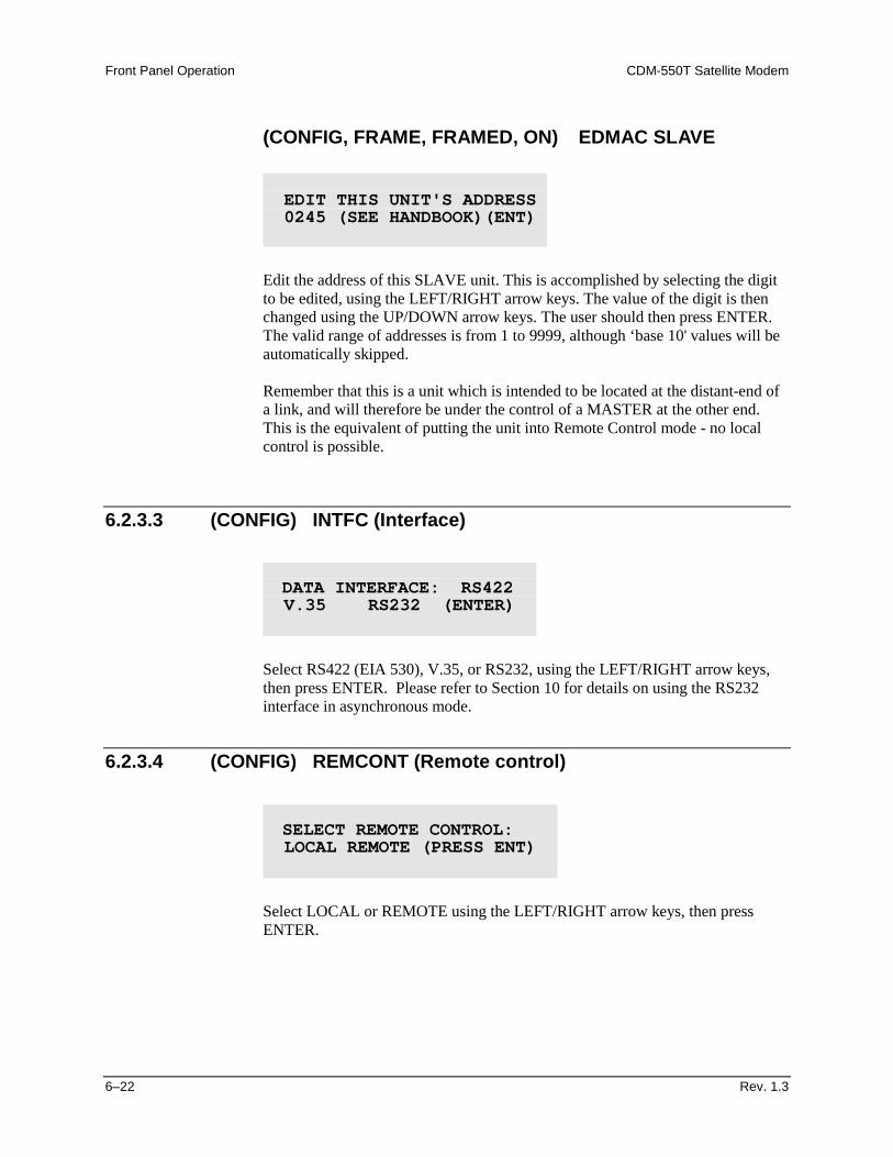
(CONFIG, FRAME, FRAMED, ON) EDMAC SLAVE
Edit the address of this SLAVE unit. This is accomplished by selecting the digit to be edited, using the LEFT/RIGHT arrow keys. The value of the digit is then changed using the UP/DOWN arrow keys. The user should then press ENTER. The valid range of addresses is from 1 to 9999, although ‘base 10' values will be automatically skipped. Remember that this is a unit which is intended to be located at the distant-end of a link, and will therefore be under the control of a MASTER at the other end. This is the equivalent of putting the unit into Remote Control mode - no local control is possible.
6.2.3.3 (CONFIG) INTFC (Interface)
Select RS422 (EIA 530), V.35, or RS232, using the LEFT/RIGHT arrow keys, then press ENTER. Please refer to Section 10 for details on using the RS232 interface in asynchronous mode.
6.2.3.4 (CONFIG) REMCONT (Remote control)
Select LOCAL or REMOTE using the LEFT/RIGHT arrow keys, then press ENTER.
EDIT THIS UNIT'S ADDRESS 0245 (SEE HANDBOOK)(ENT)
DATA INTERFACE: RS422 V.35 RS232 (ENTER)
SELECT REMOTE CONTROL: LOCAL REMOTE (PRESS ENT)
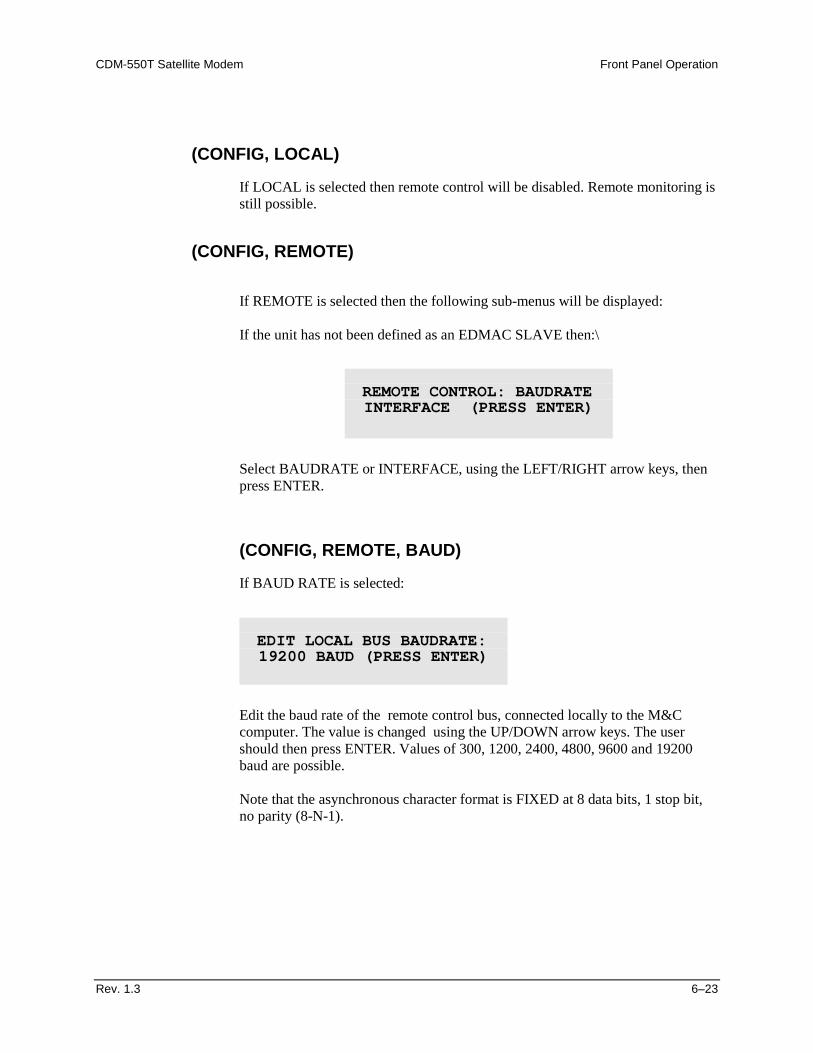
CDM-550T Satellite Modem Front Panel Operation
Rev. 1.3 6–23
(CONFIG, LOCAL)
If LOCAL is selected then remote control will be disabled. Remote monitoring is still possible.
(CONFIG, REMOTE)
If REMOTE is selected then the following sub-menus will be displayed: If the unit has not been defined as an EDMAC SLAVE then:\
Select BAUDRATE or INTERFACE, using the LEFT/RIGHT arrow keys, then press ENTER.
(CONFIG, REMOTE, BAUD)
If BAUD RATE is selected:
Edit the baud rate of the remote control bus, connected locally to the M&C computer. The value is changed using the UP/DOWN arrow keys. The user should then press ENTER. Values of 300, 1200, 2400, 4800, 9600 and 19200 baud are possible. Note that the asynchronous character format is FIXED at 8 data bits, 1 stop bit, no parity (8-N-1).
REMOTE CONTROL: BAUDRATE INTERFACE (PRESS ENTER)
EDIT LOCAL BUS BAUDRATE: 19200 BAUD (PRESS ENTER)
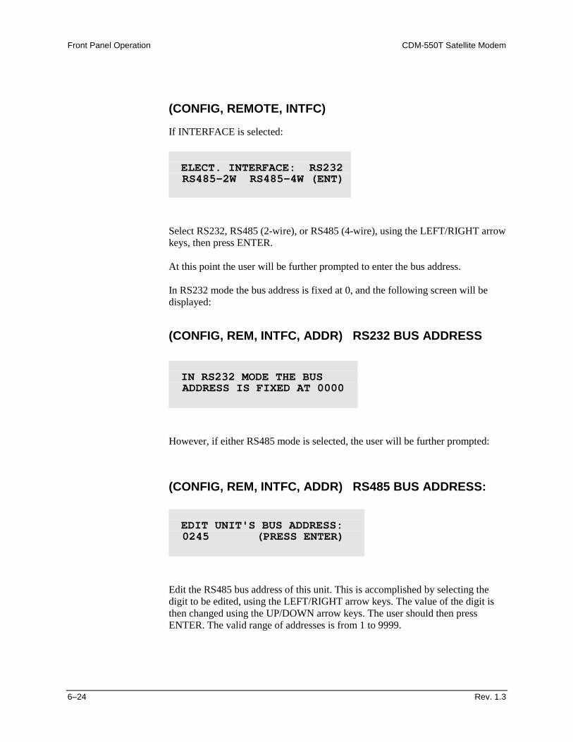
Front Panel Operation CDM-550T Satellite Modem
6–24 Rev. 1.3
(CONFIG, REMOTE, INTFC)
If INTERFACE is selected:
Select RS232, RS485 (2-wire), or RS485 (4-wire), using the LEFT/RIGHT arrow keys, then press ENTER. At this point the user will be further prompted to enter the bus address. In RS232 mode the bus address is fixed at 0, and the following screen will be displayed:
(CONFIG, REM, INTFC, ADDR) RS232 BUS ADDRESS
However, if either RS485 mode is selected, the user will be further prompted:
(CONFIG, REM, INTFC, ADDR) RS485 BUS ADDRESS:
Edit the RS485 bus address of this unit. This is accomplished by selecting the digit to be edited, using the LEFT/RIGHT arrow keys. The value of the digit is then changed using the UP/DOWN arrow keys. The user should then press ENTER. The valid range of addresses is from 1 to 9999.
ELECT. INTERFACE: RS232 RS485-2W RS485-4W (ENT)
IN RS232 MODE THE BUS ADDRESS IS FIXED AT 0000
EDIT UNIT'S BUS ADDRESS: 0245 (PRESS ENTER)
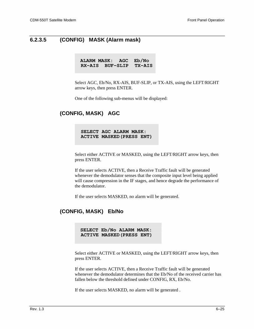
CDM-550T Satellite Modem Front Panel Operation
Rev. 1.3 6–25
6.2.3.5 (CONFIG) MASK (Alarm mask)
Select AGC, Eb/No, RX-AIS, BUF-SLIP, or TX-AIS, using the LEFT/RIGHT arrow keys, then press ENTER. One of the following sub-menus will be displayed:
(CONFIG, MASK) AGC
Select either ACTIVE or MASKED, using the LEFT/RIGHT arrow keys, then press ENTER. If the user selects ACTIVE, then a Receive Traffic fault will be generated whenever the demodulator senses that the composite input level being applied will cause compression in the IF stages, and hence degrade the performance of the demodulator. If the user selects MASKED, no alarm will be generated.
(CONFIG, MASK) Eb/No
Select either ACTIVE or MASKED, using the LEFT/RIGHT arrow keys, then press ENTER. If the user selects ACTIVE, then a Receive Traffic fault will be generated whenever the demodulator determines that the Eb/No of the received carrier has fallen below the threshold defined under CONFIG, RX, Eb/No. If the user selects MASKED, no alarm will be generated .
ALARM MASK: AGC Eb/No RX-AIS BUF-SLIP TX-AIS
SELECT AGC ALARM MASK: ACTIVE MASKED(PRESS ENT)
SELECT Eb/No ALARM MASK: ACTIVE MASKED(PRESS ENT)
Front Panel Operation CDM-550T Satellite Modem
6–26 Rev. 1.3
(CONFIG, MASK) RX-AIS
Select either ACTIVE or MASKED, using the LEFT/RIGHT arrow keys, then press ENTER. If the user selects ACTIVE, then a Receive Traffic fault will be generated whenever the demodulator senses that the ‘all ones’ condition is present in the receive data. If the user selects MASKED, no alarm will be generated.
(CONFIG, MASK) BUF-SLIP (Buffer slip)
Select either ACTIVE or MASKED, using the LEFT/RIGHT arrow keys, then press ENTER. If the user selects ACTIVE, then a Receive Traffic fault will be generated whenever the receive circuitry senses that the buffer has either underflowed, or overflowed. If the user selects MASKED, no alarm will be generated.
SEL RX-AIS ALARM MASK: ACTIVE MASKED(PRESS ENT)
SEL BUF-SLIP ALARM MASK: ACTIVE MASKED(PRESS ENT)
CDM-550T Satellite Modem Front Panel Operation
Rev. 1.3 6–27
(CONFIG, MASK) TX-AIS
Select either ACTIVE or MASKED, using the LEFT/RIGHT arrow keys, then press ENTER. If the user selects ACTIVE, then a Transmit Traffic fault will be generated whenever the transmit circuitry senses that the ‘all ones’ condition is present in the transmit data. If the user selects MASKED, no alarm will be generated .
6.2.3.6 (CONFIG) IMPED (IF impedance)
Select either 50 ohms or 75 ohms, using the LEFT/RIGHT arrow keys, then press ENTER.
SEL TX-AIS ALARM MASK: ACTIVE MASKED(PRESS ENT)
SELECT IF IMPEDANCE: 50 OHMS 75 OHMS (ENTER)
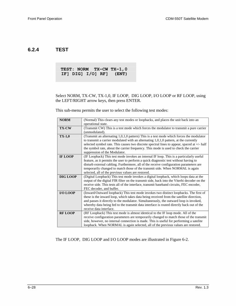
Front Panel Operation CDM-550T Satellite Modem
6–28 Rev. 1.3
6.2.4 TEST
Select NORM, TX-CW, TX-1,0, IF LOOP, DIG LOOP, I/O LOOP or RF LOOP, using the LEFT/RIGHT arrow keys, then press ENTER. This sub-menu permits the user to select the following test modes:
NORM (Normal) This clears any test modes or loopbacks, and places the unit back into an operational state.
TX-CW (Transmit CW) This is a test mode which forces the modulator to transmit a pure carrier (unmodulated).
TX-1,0 (Transmit an alternating 1,0,1,0 pattern) This is a test mode which forces the modulator to transmit a carrier modulated with an alternating 1,0,1,0 pattern, at the currently selected symbol rate. This causes two discrete spectral lines to appear, spaced at +/- half the symbol rate, about the carrier frequency. This mode is used to check the carrier suppression of the Modulator.
IF LOOP (IF Loopback) This test mode invokes an internal IF loop. This is a particularly useful feature, as it permits the user to perform a quick diagnostic test without having to disturb external cabling. Furthermore, all of the receive configuration parameters are temporarily changed to match those of the transmit side. When NORMAL is again selected, all of the previous values are restored.
DIG LOOP (Digital Loopback) This test mode invokes a digital loopback, which loops data at the output of the digital FIR filter on the transmit side, back into the Viterbi decoder on the receive side. This tests all of the interface, transmit baseband circuits, FEC encoder, FEC decoder, and buffer.
I/O LOOP (Inward/Outward loopback) This test mode invokes two distinct loopbacks. The first of these is the inward loop, which takes data being received from the satellite direction, and passes it directly to the modulator. Simultaneously, the outward loop is invoked, whereby data being fed to the transmit data interface is routed directly back out of the receive data interface.
RF LOOP (RF Loopback) This test mode is almost identical to the IF loop mode. All of the receive configuration parameters are temporarily changed to match those of the transmit side, however, no internal connection is made. This is useful for performing a satelite loopback. When NORMAL is again selected, all of the previous values are restored.
The IF LOOP, DIG LOOP and I/O LOOP modes are illustrated in Figure 6-2.
TEST: NORM TX-CW TX-1,0 IF] DIG] I/O] RF] (ENT)
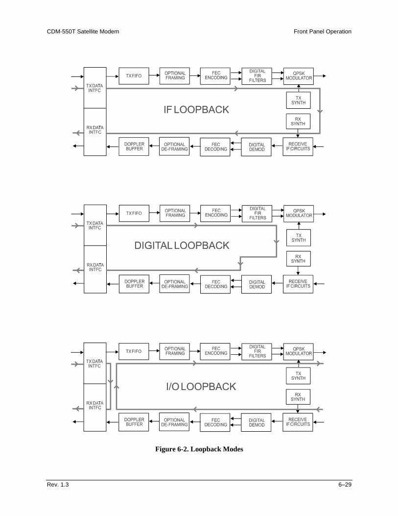
CDM-550T Satellite Modem Front Panel Operation
Rev. 1.3 6–29
Figure 6-2. Loopback Modes
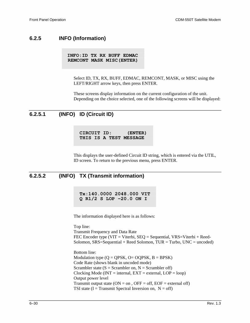
Front Panel Operation CDM-550T Satellite Modem
6–30 Rev. 1.3
6.2.5 INFO (Information)
Select ID, TX, RX, BUFF, EDMAC, REMCONT, MASK, or MISC using the LEFT/RIGHT arrow keys, then press ENTER. These screens display information on the current configuration of the unit. Depending on the choice selected, one of the following screens will be displayed:
6.2.5.1 (INFO) ID (Circuit ID)
This displays the user-defined Circuit ID string, which is entered via the UTIL, ID screen. To return to the previous menu, press ENTER.
6.2.5.2 (INFO) TX (Transmit information)
The information displayed here is as follows:
Top line:
Transmit Frequency and Data Rate FEC Encoder type (VIT = Viterbi, SEQ = Sequential, VRS=Viterbi + Reed-Solomon, SRS=Sequential + Reed Solomon, TUR = Turbo, UNC = uncoded)
Bottom line: Modulation type (Q = QPSK, O= OQPSK, B = BPSK)
Code Rate (shows blank in uncoded mode) Scrambler state (S = Scrambler on, N = Scrambler off) Clocking Mode (INT = internal, EXT = external, LOP = loop) Output power level Transmit output state (ON = on , OFF = off, EOF = external off) TSI state (I = Transmit Spectral Inversion on, N = off)
INFO:ID TX RX BUFF EDMAC REMCONT MASK MISC(ENTER)
CIRCUIT ID: (ENTER) THIS IS A TEST MESSAGE
Tx:140.0000 2048.000 VIT Q R1/2 S LOP -20.0 ON I
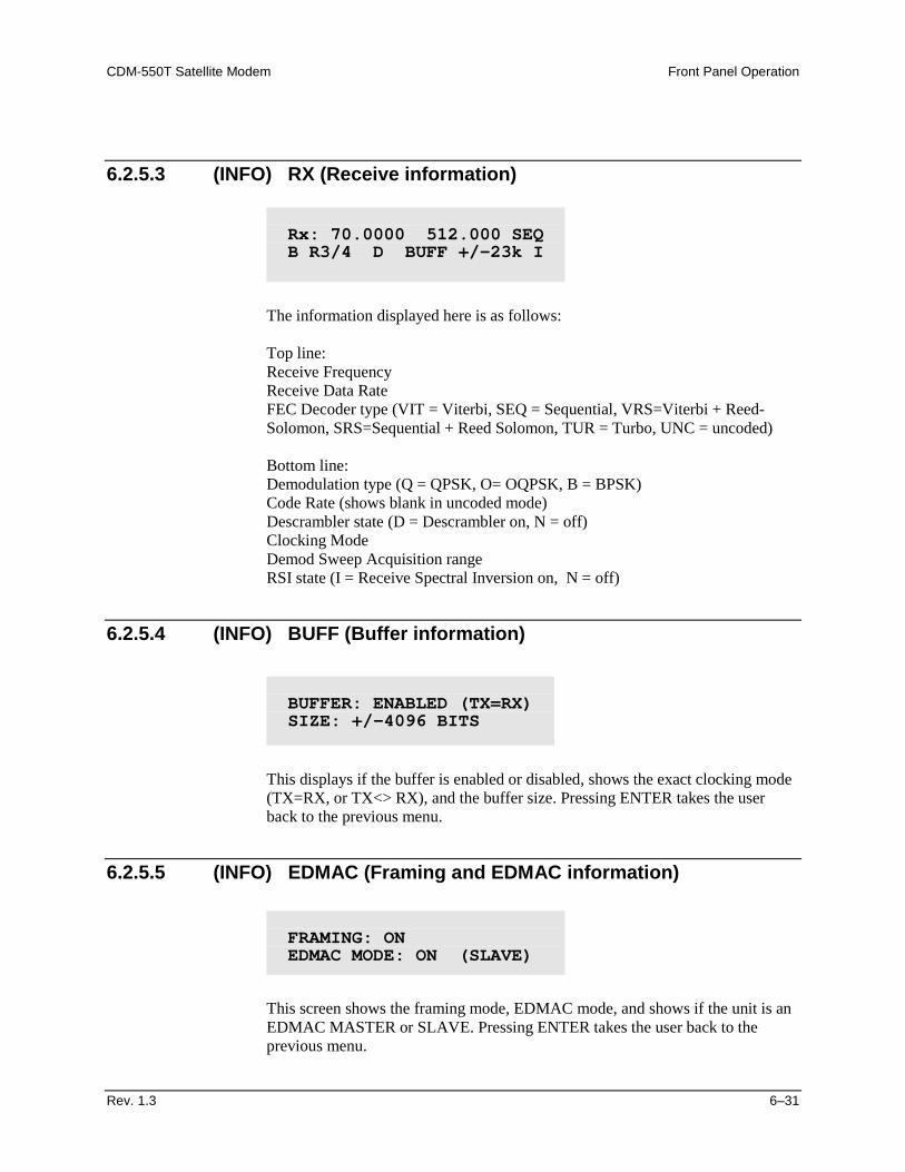
CDM-550T Satellite Modem Front Panel Operation
Rev. 1.3 6–31
6.2.5.3 (INFO) RX (Receive information)
The information displayed here is as follows:
Top line: Receive Frequency Receive Data Rate FEC Decoder type (VIT = Viterbi, SEQ = Sequential, VRS=Viterbi + Reed-Solomon, SRS=Sequential + Reed Solomon, TUR = Turbo, UNC = uncoded) Bottom line: Demodulation type (Q = QPSK, O= OQPSK, B = BPSK) Code Rate (shows blank in uncoded mode) Descrambler state (D = Descrambler on, N = off) Clocking Mode Demod Sweep Acquisition range RSI state (I = Receive Spectral Inversion on, N = off)
6.2.5.4 (INFO) BUFF (Buffer information)
This displays if the buffer is enabled or disabled, shows the exact clocking mode (TX=RX, or TX<> RX), and the buffer size. Pressing ENTER takes the user back to the previous menu.
6.2.5.5 (INFO) EDMAC (Framing and EDMAC information)
This screen shows the framing mode, EDMAC mode, and shows if the unit is an EDMAC MASTER or SLAVE. Pressing ENTER takes the user back to the previous menu.
Rx: 70.0000 512.000 SEQ B R3/4 D BUFF +/-23k I
BUFFER: ENABLED (TX=RX) SIZE: +/-4096 BITS
FRAMING: ON EDMAC MODE: ON (SLAVE)
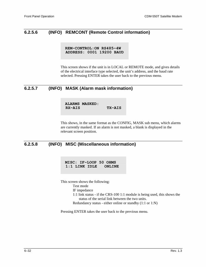
Front Panel Operation CDM-550T Satellite Modem
6–32 Rev. 1.3
6.2.5.6 (INFO) REMCONT (Remote Control information)
This screen shows if the unit is in LOCAL or REMOTE mode, and gives details of the electrical interface type selected, the unit’s address, and the baud rate selected. Pressing ENTER takes the user back to the previous menu.
6.2.5.7 (INFO) MASK (Alarm mask information)
This shows, in the same format as the CONFIG, MASK sub menu, which alarms are currently masked. If an alarm is not masked, a blank is displayed in the relevant screen position.
6.2.5.8 (INFO) MISC (Miscellaneous information)
This screen shows the following:
Test mode IF impedance 1:1 link status - if the CRS-100 1:1 module is being used, this shows the
status of the serial link between the two units. Redundancy status - either online or standby (1:1 or 1:N)
Pressing ENTER takes the user back to the previous menu.
REM-CONTROL:ON RS485-4W ADDRESS: 0001 19200 BAUD
ALARMS MASKED: RX-AIS TX-AIS
MISC: IF-LOOP 50 OHMS 1:1 LINK IDLE ONLINE
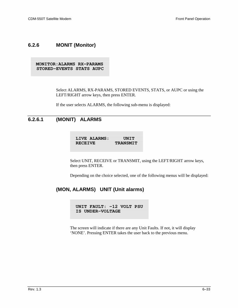
CDM-550T Satellite Modem Front Panel Operation
Rev. 1.3 6–33
6.2.6 MONIT (Monitor)
Select ALARMS, RX-PARAMS, STORED EVENTS, STATS, or AUPC or using the LEFT/RIGHT arrow keys, then press ENTER. If the user selects ALARMS, the following sub-menu is displayed:
6.2.6.1 (MONIT) ALARMS
Select UNIT, RECEIVE or TRANSMIT, using the LEFT/RIGHT arrow keys, then press ENTER. Depending on the choice selected, one of the following menus will be displayed:
(MON, ALARMS) UNIT (Unit alarms)
The screen will indicate if there are any Unit Faults. If not, it will display ‘NONE’. Pressing ENTER takes the user back to the previous menu.
MONITOR:ALARMS RX-PARAMS STORED-EVENTS STATS AUPC
LIVE ALARMS: UNIT RECEIVE TRANSMIT
UNIT FAULT: -12 VOLT PSU IS UNDER-VOLTAGE
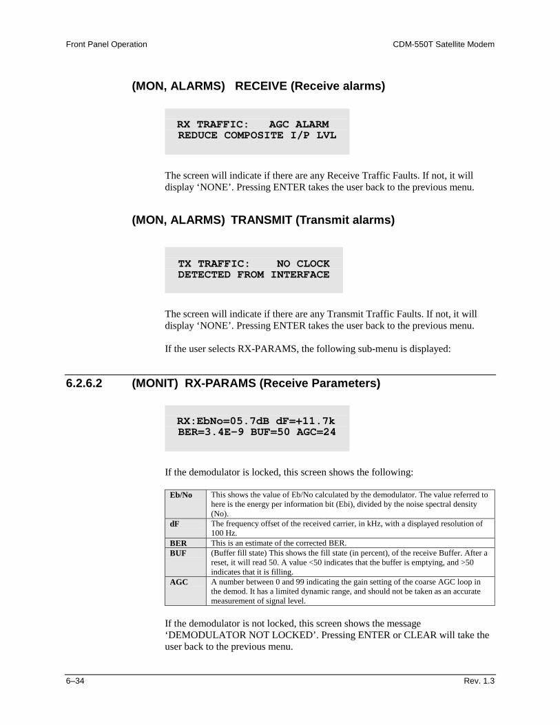
Front Panel Operation CDM-550T Satellite Modem
6–34 Rev. 1.3
(MON, ALARMS) RECEIVE (Receive alarms)
The screen will indicate if there are any Receive Traffic Faults. If not, it will display ‘NONE’. Pressing ENTER takes the user back to the previous menu.
(MON, ALARMS) TRANSMIT (Transmit alarms)
The screen will indicate if there are any Transmit Traffic Faults. If not, it will display ‘NONE’. Pressing ENTER takes the user back to the previous menu. If the user selects RX-PARAMS, the following sub-menu is displayed:
6.2.6.2 (MONIT) RX-PARAMS (Receive Parameters)
If the demodulator is locked, this screen shows the following:
Eb/No This shows the value of Eb/No calculated by the demodulator. The value referred to
here is the energy per information bit (Ebi), divided by the noise spectral density (No).
dF The frequency offset of the received carrier, in kHz, with a displayed resolution of 100 Hz.
BER This is an estimate of the corrected BER. BUF (Buffer fill state) This shows the fill state (in percent), of the receive Buffer. After a
reset, it will read 50. A value <50 indicates that the buffer is emptying, and >50 indicates that it is filling.
AGC A number between 0 and 99 indicating the gain setting of the coarse AGC loop in the demod. It has a limited dynamic range, and should not be taken as an accurate measurement of signal level.
If the demodulator is not locked, this screen shows the message ‘DEMODULATOR NOT LOCKED’. Pressing ENTER or CLEAR will take the user back to the previous menu.
RX TRAFFIC: AGC ALARM REDUCE COMPOSITE I/P LVL
TX TRAFFIC: NO CLOCK DETECTED FROM INTERFACE
RX:EbNo=05.7dB dF=+11.7k BER=3.4E-9 BUF=50 AGC=24
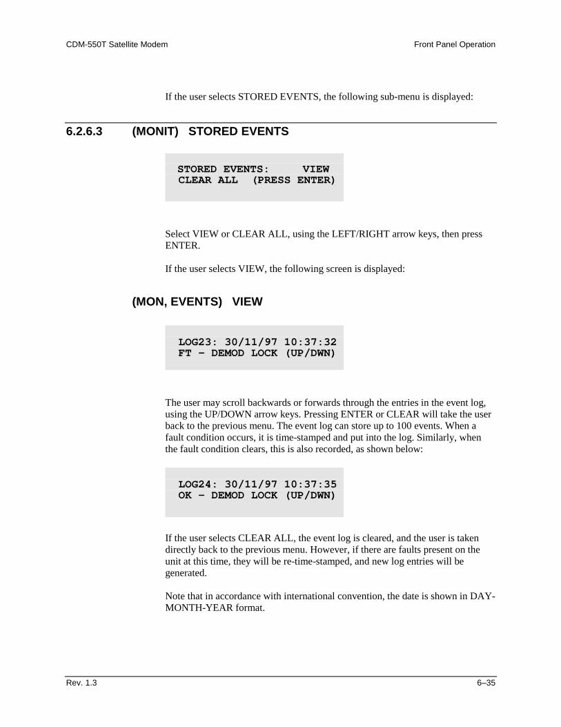
CDM-550T Satellite Modem Front Panel Operation
Rev. 1.3 6–35
If the user selects STORED EVENTS, the following sub-menu is displayed:
6.2.6.3 (MONIT) STORED EVENTS
Select VIEW or CLEAR ALL, using the LEFT/RIGHT arrow keys, then press ENTER. If the user selects VIEW, the following screen is displayed:
(MON, EVENTS) VIEW
The user may scroll backwards or forwards through the entries in the event log, using the UP/DOWN arrow keys. Pressing ENTER or CLEAR will take the user back to the previous menu. The event log can store up to 100 events. When a fault condition occurs, it is time-stamped and put into the log. Similarly, when the fault condition clears, this is also recorded, as shown below:
If the user selects CLEAR ALL, the event log is cleared, and the user is taken directly back to the previous menu. However, if there are faults present on the unit at this time, they will be re-time-stamped, and new log entries will be generated. Note that in accordance with international convention, the date is shown in DAY-MONTH-YEAR format.
STORED EVENTS: VIEW CLEAR ALL (PRESS ENTER)
LOG23: 30/11/97 10:37:32 FT - DEMOD LOCK (UP/DWN)
LOG24: 30/11/97 10:37:35 OK - DEMOD LOCK (UP/DWN)
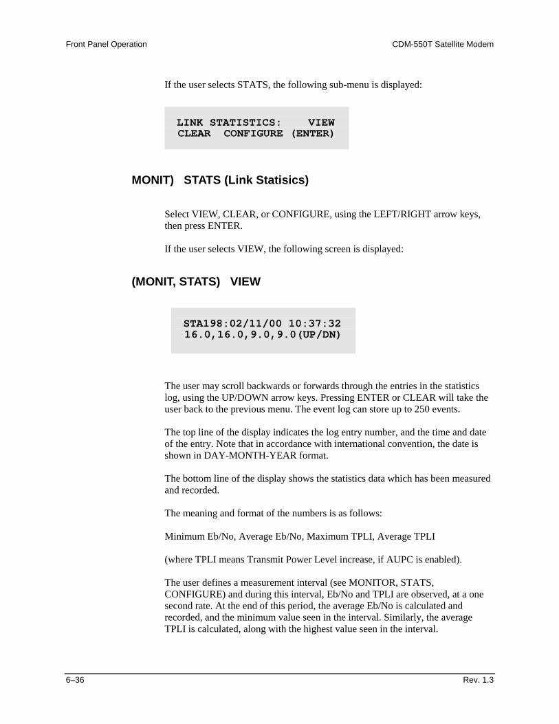
Front Panel Operation CDM-550T Satellite Modem
6–36 Rev. 1.3
If the user selects STATS, the following sub-menu is displayed:
MONIT) STATS (Link Statisics)
Select VIEW, CLEAR, or CONFIGURE, using the LEFT/RIGHT arrow keys, then press ENTER. If the user selects VIEW, the following screen is displayed:
(MONIT, STATS) VIEW
The user may scroll backwards or forwards through the entries in the statistics log, using the UP/DOWN arrow keys. Pressing ENTER or CLEAR will take the user back to the previous menu. The event log can store up to 250 events. The top line of the display indicates the log entry number, and the time and date of the entry. Note that in accordance with international convention, the date is shown in DAY-MONTH-YEAR format. The bottom line of the display shows the statistics data which has been measured and recorded. The meaning and format of the numbers is as follows: Minimum Eb/No, Average Eb/No, Maximum TPLI, Average TPLI (where TPLI means Transmit Power Level increase, if AUPC is enabled). The user defines a measurement interval (see MONITOR, STATS, CONFIGURE) and during this interval, Eb/No and TPLI are observed, at a one second rate. At the end of this period, the average Eb/No is calculated and recorded, and the minimum value seen in the interval. Similarly, the average TPLI is calculated, along with the highest value seen in the interval.
LINK STATISTICS: VIEW CLEAR CONFIGURE (ENTER)
STA198:02/11/00 10:37:32 16.0,16.0,9.0,9.0(UP/DN)
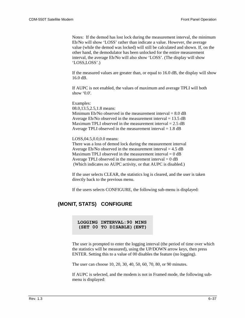
CDM-550T Satellite Modem Front Panel Operation
Rev. 1.3 6–37
Notes: If the demod has lost lock during the measurement interval, the minimum Eb/No will show ‘LOSS’ rather than indicate a value. However, the average value (while the demod was locked) will still be calculated and shown. If, on the other hand, the demodulator has been unlocked for the entire measurement interval, the average Eb/No will also show ‘LOSS’. (The display will show ‘LOSS,LOSS’.)
If the measured values are greater than, or equal to 16.0 dB, the display will show 16.0 dB. If AUPC is not enabled, the values of maximum and average TPLI will both show ‘0.0'. Examples: 08.0,13.5,2.5,1.8 means: Minimum Eb/No observed in the measurement interval = 8.0 dB Average Eb/No observed in the measurement interval = 13.5 dB Maximum TPLI observed in the measurement interval = 2.5 dB Average TPLI observed in the measurement interval = 1.8 dB LOSS,04.5,0.0,0.0 means: There was a loss of demod lock during the measurement interval Average Eb/No observed in the measurement interval = 4.5 dB Maximum TPLI observed in the measurement interval = 0 dB Average TPLI observed in the measurement interval = 0 dB (Which indicates no AUPC activity, or that AUPC is disabled.) If the user selects CLEAR, the statistics log is cleared, and the user is taken directly back to the previous menu. If the users selects CONFIGURE, the following sub-menu is displayed:
(MONIT, STATS) CONFIGURE
The user is prompted to enter the logging interval (the period of time over which the statistics will be measured), using the UP/DOWN arrow keys, then press ENTER. Setting this to a value of 00 disables the feature (no logging). The user can choose 10, 20, 30, 40, 50, 60, 70, 80, or 90 minutes.
If AUPC is selected, and the modem is not in Framed mode, the following sub-menu is displayed:
LOGGING INTERVAL:90 MINS (SET 00 TO DISABLE)(ENT)
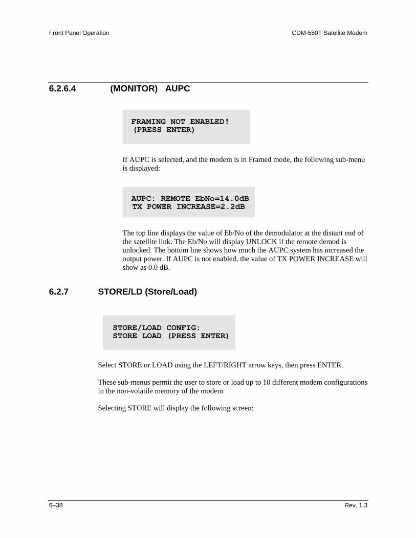
Front Panel Operation CDM-550T Satellite Modem
6–38 Rev. 1.3
6.2.6.4 (MONITOR) AUPC
If AUPC is selected, and the modem is in Framed mode, the following sub-menu is displayed:
The top line displays the value of Eb/No of the demodulator at the distant end of the satellite link. The Eb/No will display UNLOCK if the remote demod is unlocked. The bottom line shows how much the AUPC system has increased the output power. If AUPC is not enabled, the value of TX POWER INCREASE will show as 0.0 dB.
6.2.7 STORE/LD (Store/Load)
Select STORE or LOAD using the LEFT/RIGHT arrow keys, then press ENTER. These sub-menus permit the user to store or load up to 10 different modem configurations in the non-volatile memory of the modem Selecting STORE will display the following screen:
FRAMING NOT ENABLED! (PRESS ENTER)
AUPC: REMOTE EbNo=14.0dB TX POWER INCREASE=2.2dB
STORE/LOAD CONFIG: STORE LOAD (PRESS ENTER)
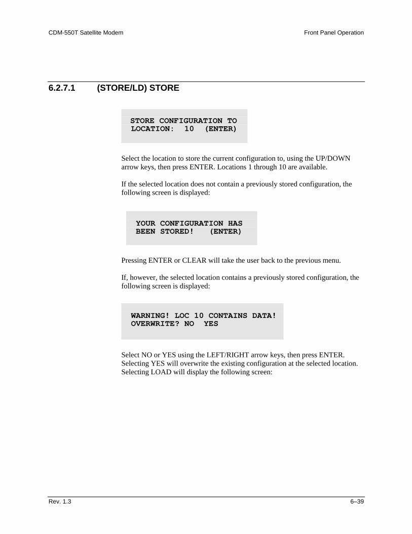
CDM-550T Satellite Modem Front Panel Operation
Rev. 1.3 6–39
6.2.7.1 (STORE/LD) STORE
Select the location to store the current configuration to, using the UP/DOWN arrow keys, then press ENTER. Locations 1 through 10 are available. If the selected location does not contain a previously stored configuration, the following screen is displayed:
Pressing ENTER or CLEAR will take the user back to the previous menu. If, however, the selected location contains a previously stored configuration, the following screen is displayed:
Select NO or YES using the LEFT/RIGHT arrow keys, then press ENTER. Selecting YES will overwrite the existing configuration at the selected location. Selecting LOAD will display the following screen:
STORE CONFIGURATION TO LOCATION: 10 (ENTER)
YOUR CONFIGURATION HAS BEEN STORED! (ENTER)
WARNING! LOC 10 CONTAINS DATA! OVERWRITE? NO YES
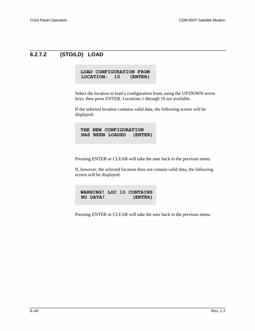
Front Panel Operation CDM-550T Satellite Modem
6–40 Rev. 1.3
6.2.7.2 (STO/LD) LOAD
Select the location to load a configuration from, using the UP/DOWN arrow keys, then press ENTER. Locations 1 through 10 are available. If the selected location contains valid data, the following screen will be displayed:
Pressing ENTER or CLEAR will take the user back to the previous menu. If, however, the selected location does not contain valid data, the following screen will be displayed:
Pressing ENTER or CLEAR will take the user back to the previous menu.
LOAD CONFIGURATION FROM LOCATION: 10 (ENTER)
THE NEW CONFIGURATION HAS BEEN LOADED (ENTER)
WARNING! LOC 10 CONTAINS NO DATA! (ENTER)
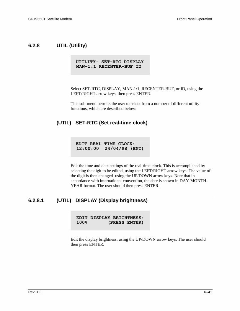
CDM-550T Satellite Modem Front Panel Operation
Rev. 1.3 6–41
6.2.8 UTIL (Utility)
Select SET-RTC, DISPLAY, MAN-1:1, RECENTER-BUF, or ID, using the LEFT/RIGHT arrow keys, then press ENTER. This sub-menu permits the user to select from a number of different utility functions, which are described below:
(UTIL) SET-RTC (Set real-time clock)
Edit the time and date settings of the real-time clock. This is accomplished by selecting the digit to be edited, using the LEFT/RIGHT arrow keys. The value of the digit is then changed using the UP/DOWN arrow keys. Note that in accordance with international convention, the date is shown in DAY-MONTH-YEAR format. The user should then press ENTER.
6.2.8.1 (UTIL) DISPLAY (Display brightness)
Edit the display brightness, using the UP/DOWN arrow keys. The user should then press ENTER.
UTILITY: SET-RTC DISPLAY MAN-1:1 RECENTER-BUF ID
EDIT REAL TIME CLOCK: 12:00:00 24/04/98 (ENT)
EDIT DISPLAY BRIGHTNESS: 100% (PRESS ENTER)
Front Panel Operation CDM-550T Satellite Modem
6–42 Rev. 1.3
6.2.8.2 (UTIL) MAN-1:1 (Manual 1:1 switchover)
If the unit is part of a 1:1 redundant pair of modems, and this unit, is currently on-line, pressing ENTER will cause the unit to switch to standby.
6.2.8.3 (UTIL) RECENTER-BUF (re-center buffer)
Pressing ENTER will cause a forced re-centering of the Plesiochronous/Doppler buffer.
6.2.8.4 (UTIL) ID (Circuit ID)
Edit the Circuit ID string, using the LEFT/RIGHT and UP/DOWN arrow keys. Only the bottom line is available (24 characters). The cursor selects the position on the bottom line (LEFT/RIGHT) and the character is then edited (UP/DOWN). The following characters are available: Space ( ) * + - , . / 0-9 and A-Z. When the user has composed the string, press ENTER.
PRESS ENT TO FORCE THIS UNIT TO STDBY (1:1 ONLY)
PRESS ENTER TO RE-CENTER THE RECEIVE BUFFER
EDIT CIRCUIT ID: (ENTER) THIS IS A TEST MESSAGE
Rev. 1.3 7–1
7Chapter 7. FORWARD ERROR
CORRECTION OPTIONS
7.1 Introduction
As standard, the CDM-550T Modem is equipped with two Forward Error Correction Decoders, Viterbi and Sequential. The constraint lengths and encoding polynomials are compatible with the vast majority of existing modems from other manufacturers, and Comtech EF Data has performed compatibility testing to ensure inter-operability. As an option, the CDM-550T may be fitted with two additional Forward Error Correction (FEC) devices. The first is a concatenated Reed-Solomon Codec. This is always used in conjunction with, rather than instead of, the main FEC method (Viterbi or Sequential). It comprises a small daughter card, and may be fitted at the factory at the time of order, or may be added by the user at a later date. The second option is Comtech EF Data’s Turbo Product Codec, which is an entirely stand-alone method of FEC. This too is a small daughter card.
7.2 Viterbi
The combination of convolutional coding and Viterbi decoding has become an almost universal standard for satellite communications. The CDM-550T complies with the Intelsat IESS 308/309 standards for Viterbi decoding with a constraint length of seven. This is a de facto standard, even in a closed network environment, which means almost guaranteed inter-operability with other manufacturer’s equipment. It provides very useful levels of coding gain, and its short decoding delay and error-burst characteristics make it particularly suitable for low data rate coded voice applications. It has a short
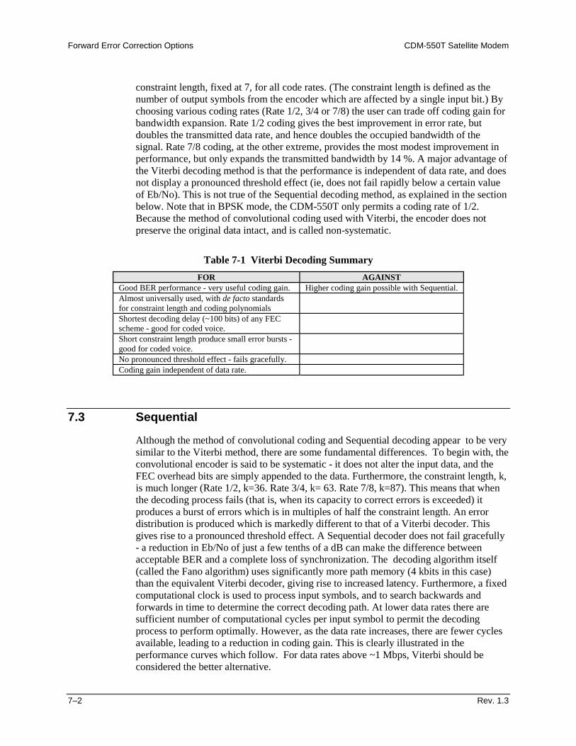
Forward Error Correction Options CDM-550T Satellite Modem
7–2 Rev. 1.3
constraint length, fixed at 7, for all code rates. (The constraint length is defined as the number of output symbols from the encoder which are affected by a single input bit.) By choosing various coding rates (Rate 1/2, 3/4 or 7/8) the user can trade off coding gain for bandwidth expansion. Rate 1/2 coding gives the best improvement in error rate, but doubles the transmitted data rate, and hence doubles the occupied bandwidth of the signal. Rate 7/8 coding, at the other extreme, provides the most modest improvement in performance, but only expands the transmitted bandwidth by 14 %. A major advantage of the Viterbi decoding method is that the performance is independent of data rate, and does not display a pronounced threshold effect (ie, does not fail rapidly below a certain value of Eb/No). This is not true of the Sequential decoding method, as explained in the section below. Note that in BPSK mode, the CDM-550T only permits a coding rate of 1/2. Because the method of convolutional coding used with Viterbi, the encoder does not preserve the original data intact, and is called non-systematic.
Table 7-1 Viterbi Decoding Summary FOR AGAINST
Good BER performance - very useful coding gain. Higher coding gain possible with Sequential. Almost universally used, with de facto standards for constraint length and coding polynomials
Shortest decoding delay (~100 bits) of any FEC scheme - good for coded voice.
Short constraint length produce small error bursts - good for coded voice.
No pronounced threshold effect - fails gracefully. Coding gain independent of data rate.
7.3 Sequential
Although the method of convolutional coding and Sequential decoding appear to be very similar to the Viterbi method, there are some fundamental differences. To begin with, the convolutional encoder is said to be systematic - it does not alter the input data, and the FEC overhead bits are simply appended to the data. Furthermore, the constraint length, k, is much longer (Rate 1/2, k=36. Rate 3/4, k= 63. Rate 7/8, k=87). This means that when the decoding process fails (that is, when its capacity to correct errors is exceeded) it produces a burst of errors which is in multiples of half the constraint length. An error distribution is produced which is markedly different to that of a Viterbi decoder. This gives rise to a pronounced threshold effect. A Sequential decoder does not fail gracefully - a reduction in Eb/No of just a few tenths of a dB can make the difference between acceptable BER and a complete loss of synchronization. The decoding algorithm itself (called the Fano algorithm) uses significantly more path memory (4 kbits in this case) than the equivalent Viterbi decoder, giving rise to increased latency. Furthermore, a fixed computational clock is used to process input symbols, and to search backwards and forwards in time to determine the correct decoding path. At lower data rates there are sufficient number of computational cycles per input symbol to permit the decoding process to perform optimally. However, as the data rate increases, there are fewer cycles available, leading to a reduction in coding gain. This is clearly illustrated in the performance curves which follow. For data rates above ~1 Mbps, Viterbi should be considered the better alternative.
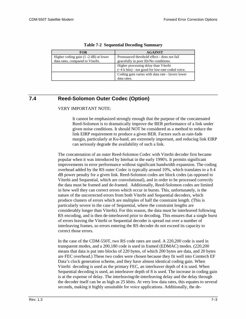
CDM-550T Satellite Modem Forward Error Correction Options
Rev. 1.3 7–3
Table 7-2 Sequential Decoding Summary FOR AGAINST
Higher coding gain (1 -2 dB) at lower data rates, compared to Viterbi.
Pronounced threshold effect - does not fail gracefully in poor Eb/No conditions.
Higher processing delay than Viterbi (~4 k bits) - not good for low-rate coded voice.
Coding gain varies with data rate - favors lower data rates.
7.4 Reed-Solomon Outer Codec (Option)
VERY IMPORTANT NOTE:
It cannot be emphasized strongly enough that the purpose of the concatenated Reed-Solomon is to dramatically improve the BER performance of a link under given noise conditions. It should NOT be considered as a method to reduce the link EIRP requirement to produce a given BER. Factors such as rain-fade margin, particularly at Ku-band, are extremely important, and reducing link EIRP can seriously degrade the availability of such a link.
The concatenation of an outer Reed-Solomon Codec with Viterbi decoder first became popular when it was introduced by Intelsat in the early 1990's. It permits significant improvements in error performance without significant bandwidth expansion. The coding overhead added by the RS outer Codec is typically around 10%, which translates to a 0.4 dB power penalty for a given link. Reed-Solomon codes are block codes (as opposed to Viterbi and Sequential, which are convolutional), and in order to be processed correctly the data must be framed and de-framed. Additionally, Reed-Solomon codes are limited in how well they can correct errors which occur in bursts. This, unfortunately, is the nature of the uncorrected errors from both Viterbi and Sequential decoders, which produce clusters of errors which are multiples of half the constraint length. (This is particularly severe in the case of Sequential, where the constraint lengths are considerably longer than Viterbi). For this reason, the data must be interleaved following RS encoding, and is then de-interleaved prior to decoding. This ensures that a single burst of errors leaving the Viterbi or Sequential decoder is spread out over a number of interleaving frames, so errors entering the RS decoder do not exceed its capacity to correct those errors. In the case of the CDM-550T, two RS code rates are used. A 220,200 code is used in transparent modes, and a 200,180 code is used in framed (EDMAC) modes. (220,200 means that data is put into blocks of 220 bytes, of which 200 bytes are data, and 20 bytes are FEC overhead.) These two codes were chosen because they fit well into Comtech EF Data’s clock generation scheme, and they have almost identical coding gain. When Viterbi decoding is used as the primary FEC, an interleaver depth of 4 is used. When Sequential decoding is used, an interleaver depth of 8 is used. The increase in coding gain is at the expense of delay. The interleaving/de-interleaving delay and the delay through the decoder itself can be as high as 25 kbits. At very low data rates, this equates to several seconds, making it highly unsuitable for voice applications. Additionally, the de-
Forward Error Correction Options CDM-550T Satellite Modem
7–4 Rev. 1.3
interleaver frame synchronization method can add significantly to the time taken for the demodulator to declare acquisition. A characteristic of concatenated RS coding is the very pronounced threshold effect. For any given modem design, there will be a threshold value of Eb/No below which the demodulator cannot stay synchronized. This may be due to the carrier-recovery circuits, or the synchronization threshold of the primary FEC device, or both. In the CDM-550T, and Rate 1/2 operation, this threshold is around 4 dB Eb/No. Below this value, operation is not possible, but above this value, the error performance of the concatenated RS system produces exceptionally low error rates for a very small increase in Eb/No.
CAUTION
Care should be taken not to operate the demodulator near its sync threshold. Small fluctuations in Eb/No may cause total loss of the link, with the subsequent need for the demodulator to re-acquire the signal.
Table 7-3 Concatenated RS Coding Summary FOR AGAINST
Exceptionally good BER performance - several orders of magnitude improvement in link BER under given link conditions.
Very pronounced threshold effect - does not fail gracefully in poor Eb/No conditions. Additional coding overhead actually degrades sync threshold, and reduces link fade margin.
Very small additional bandwidth expansion Significant processing delay (~25 kbits) - not good for voice.
Easy field upgrade in CDM-550T
Adds to demod acquisition time.
7.5 Turbo Product Codec (Option)
Turbo coding is an FEC technique developed within the last few years, which delivers significant performance improvements compared to more traditional techniques. Unlike the popular method of concatenating a Reed Solomon codec with a primary FEC codec, Turbo Coding is an entirely stand-alone method. It does not require the complex interleaving/de-interleaving of the RS approach, and consequently, decoding delays are significantly reduced - see below. Two general classes of Turbo Codes have been developed, Turbo Convolutional Codes (TCC), and Turbo Product Codes (TPC, a block coding technique). TCC suffers from an irreducible BER of approximately 1 x 10⁻⁷, and consequently, a Reed-Solomon codec may be added in order to achieve an acceptably low BER. For delay-sensitive applications this may be unacceptable, and the implementation complexity of the TCC approach is high. For these reasons Comtech EF Data has chosen to implement an FEC codec based on TPC. A Turbo Product Code is a 2 or 3 dimensional array of block codes. Encoding is relatively straightforward, but decoding is a very complex process requiring multiple iterations of processing for maximum performance to be achieved. When Comtech EF Data first introduced the Turbo Coding option in the CDM-550T, only Rate 3/4 QPSK was offered. Firmware Version 1.19 has subsequently added
CDM-550T Satellite Modem Forward Error Correction Options
Rev. 1.3 7–5
OQPSK operation. These are excellent choices for applications where maximum bandwidth efficiency is desired, in combination with high coding gain. However, with Firmware Version 1.15 (and later) Comtech EF Data has introduced two further code rates - Rate 21/44 BPSK (very close to Rate 1/2) and Rate 5/16 BPSK (very close to Rate 1/3). These two rates were developed to address an entirely different case, namely that of transmission from very small antennas, with limited transmitter power. For a dish antenna, the gain is directly proportional to its area, and the lower the gain, the less directional the antenna becomes. Thus, in satellite transmission, even though the dish may be perfectly pointed at the desired satellite, if the beamwidth is wide enough, adjacent satellites in the orbital arc will also be illuminated. This is a potential source of interference, and for this reason the ITU (International Telecommunications Union) place strict limits on the power spectral density (also referred to as flux density) of signals arriving at adjacent satellites. One obvious method to reduce the level is to spread the transmitted signal over as wide a bandwidth as possible. In the past, this has sometimes been achieved using a Spread Spectrum modulation format, but this has severe penalties as far as demodulator complexity is concerned. However, by using BPSK modulation, and high FEC code rates (up to Rate 1/3, for example) the power spectral density may be reduced. Taking Rate 1/2 QPSK as a baseline, moving to Rate 5/16 BPSK Turbo Product Coding gives an immediate reduction in power spectral density of 5.0 dB. Furthermore, the increased coding gain of this FEC method allows a further reduction in transmitter power. Using Rate 1/2 Viterbi with concatenated Reed-Solomon as a baseline example, Rate 5/16 provides 1.5 - 2.0 dB improvement in coding gain. Putting these two factors together yields an overall reduction in power spectral density of approximately 7.0 dB. This simultaneously permits a smaller antenna, and reduced transmitter power. The disadvantage is the increased spectral occupancy of the carrier, and it will depend on the particular satellite operator to determine if this poses a severe economic problem. When operating at these higher code rates (21/44 and 5/16), the demodulator is forced to operate in a region where the Ebt/No (also referred to as Es/No) is negative - in other words, there is more noise than signal. For this reason it is more difficult for the demodulator to accurately measure the Eb/No, and so users may see more variation than normal when viewing the Eb/No on the RX PARAMETERS screen, and when operating near threshold. This is most pronounced in the case of Rate 5/16. One unexpected advantage of the Turbo Product Coding method is that, unlike concatenated Reed-Solomon methods, there is no pronounced threshold effect. The demodulator and FEC codec can stay locked down to very low values of Eb/No, but at this level the output BER becomes unusable (around 1 x 10⁻²).
Forward Error Correction Options CDM-550T Satellite Modem
7–6 Rev. 1.3
7.5.1 End-to-End Processing Delay
In many cases, FEC methods which provide increased coding gain do so at the expense of increased processing delay. However, with TPC, this increase in delay is very modest. The table below shows, for the CDM-550T, the processing delays for the major FEC types, including the three TPC modes:
FEC Mode (64 kbps data rate) End-to-end delay, ms Viterbi, Rate 1/2 12 Sequential, Rate 1/2 74 Viterbi Rate 1/2 + Reed Solomon 266 Sequential Rate 1/2 + Reed Solomon 522 Turbo Product Coding, Rate 3/4, QPSK/OQPSK 79 Turbo Product Coding, Rate 21/44, BPSK 64 Turbo Product Coding, Rate 5/16, BPSK 48
(Note that in all cases, the delay is inversely proportional to data rate, so for 128 kbps, the delay values would be half of those shown above.) It can be clearly seen that the concatentaed Reed-Solomon cases increase the delay very significantly (due mainly to interleaving/de-interleaving), while the TPC cases yield delays which are less than or equal to Sequential decoding.
FOR AGAINST Exceptionally good BER performance - significant improvement compared with every other FEC method in use today
Nothing!
No pronounced threshold effect - fails gracefully Exceptional bandwidth efficiency for Rate 3/4 QPSK - 40% less than Viterbi and concatenated Reed-Solomon
Coding gain independent of data rate (in this implementation) Low decoding delay Easy field upgrade in CDM-550T
CDM-550T Satellite Modem Forward Error Correction Options
Rev. 1.3 7–7
7.6 Uncoded Operation (No FEC)
There are occasions where a user may wish to operate a satellite link with no forward error correction of any kind. For this reason, the CDM-550T offers this uncoded mode for all three modulation types - BPSK, QPSK and OQPSK. However, the user should be aware of some of the implications of using this approach. PSK demodulators have two inherent undesirable features. The first of these is known as ‘phase ambiguity’, and is due to the fact the demodulator does not have any absolute phase reference, and in the process of carrier recovery, the demodulator can lock up in any of K phase states, where K = 2 for BPSK, K = 4 for QPSK/OQPSK. Without the ability to resolve these ambiguous states there would be a 1-in-2 chance that the data at the output of the demodulator would be wrong, in the case of BPSK. For QPSK, the probability would be 3 in 4. The problem is solved in the case of BPSK by differentially encoding the data prior to transmission, and then performing the inverse decoding process. This is a very simple process, but has the disadvantage that it doubles the receive BER. For every bit error the demodulator produces, the differential decoder produces two. The problem for QPSK is more complex, as there are 4 possible lock states, leading to 4 ambiguities. When FEC is employed, the lock state of the FEC decoder can be used to resolve two of the four ambiguities, and the remaining two can be resolved using serial differential encoding/decoding. However, when no FEC is being used, another scheme entirely must be used. Therefore, in QPSK, a parallel differential encoding/decoding technique is used, but has the disadvantage that it again doubles the receive BER. OQPSK is a different situation again, where the ambiguities result not only from not having an absolute phase reference, but also not knowing which of the two parallel paths in the demod, I or Q, contains the half-symbol delay. Another type of differential encoding is used, but yet again the error rate is doubled, compared to ideal. NOTE: Whenever uncoded operation is selected, the modem automatically uses the differential encoder/decoder appropriate for the modulation type. It cannot be disabled. The second problem inherent in PSK demodulators is that of ‘data false locking’. In order to accomplish the task of carrier recovery, the demodulator must use a non-linear process. A second-order non-linearity is used for BPSK, and a fourth-order non-linearity is used for QPSK. When data at a certain symbol rate is used to modulate the carrier, the demodulator can lock at incorrect frequencies, spaced at intervals of one-quarter of the symbol rate away from the carrier. Fortunately, when FEC decoding is used, the decoder synchronization state can be used to verify the correct lock point has been achieved, and to reject the false locks.
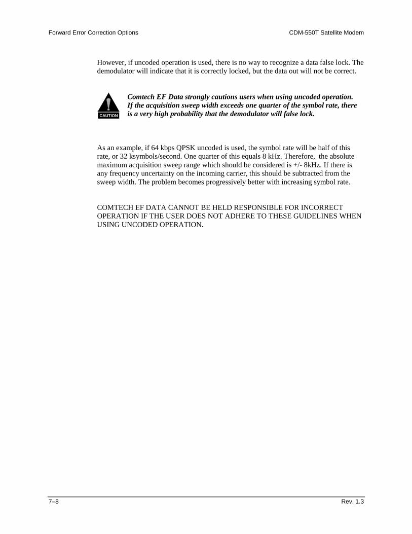
Forward Error Correction Options CDM-550T Satellite Modem
7–8 Rev. 1.3
However, if uncoded operation is used, there is no way to recognize a data false lock. The demodulator will indicate that it is correctly locked, but the data out will not be correct.
CAUTION
Comtech EF Data strongly cautions users when using uncoded operation. If the acquisition sweep width exceeds one quarter of the symbol rate, there is a very high probability that the demodulator will false lock.
As an example, if 64 kbps QPSK uncoded is used, the symbol rate will be half of this rate, or 32 ksymbols/second. One quarter of this equals 8 kHz. Therefore, the absolute maximum acquisition sweep range which should be considered is +/- 8kHz. If there is any frequency uncertainty on the incoming carrier, this should be subtracted from the sweep width. The problem becomes progressively better with increasing symbol rate. COMTECH EF DATA CANNOT BE HELD RESPONSIBLE FOR INCORRECT OPERATION IF THE USER DOES NOT ADHERE TO THESE GUIDELINES WHEN USING UNCODED OPERATION.
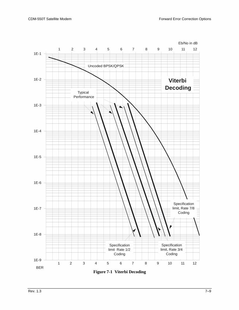
CDM-550T Satellite Modem Forward Error Correction Options
Rev. 1.3 7–9
Figure 7-1 Viterbi Decoding
1E-9
1E-8
1E-7
1E-6
1E-5
1E-4
1E-3
1E-2
1E-11 2 3 4 5 6 7 8 9 10 11 12
Eb/No in dB
Specificationlimit Rate 1/2
Coding
Uncoded BPSK/QPSK
TypicalPerformance
Specificationlimit, Rate 3/4
Coding
1 2 3 4 5 6 7 8 9 10 11 12
Specificationlimit, Rate 7/8
Coding
BER
ViterbiDecoding
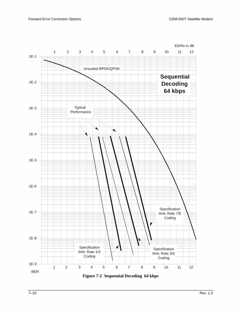
Forward Error Correction Options CDM-550T Satellite Modem
7–10 Rev. 1.3
Figure 7-2 Sequential Decoding 64 kbps
1E-9
1E-8
1E-7
1E-6
1E-5
1E-4
1E-3
1E-2
1E-11 2 3 4 5 6 7 8 9 10 11 12
Eb/No in dB
Specificationlimit Rate 1/2
Coding
Uncoded BPSK/QPSK
TypicalPerformance
Specificationlimit, Rate 3/4
Coding
1 2 3 4 5 6 7 8 9 10 11 12
Specificationlimit, Rate 7/8
Coding
BER
SequentialDecoding64 kbps
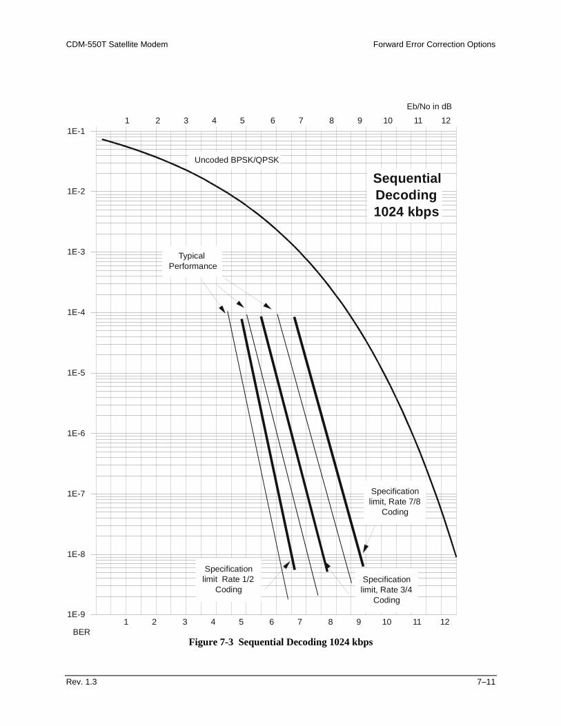
CDM-550T Satellite Modem Forward Error Correction Options
Rev. 1.3 7–11
Figure 7-3 Sequential Decoding 1024 kbps
1E-9
1E-8
1E-7
1E-6
1E-5
1E-4
1E-3
1E-2
1E-11 2 3 4 5 6 7 8 9 10 11 12
Eb/No in dB
Specificationlimit Rate 1/2
Coding
Uncoded BPSK/QPSK
TypicalPerformance
Specificationlimit, Rate 3/4
Coding
1 2 3 4 5 6 7 8 9 10 11 12
Specificationlimit, Rate 7/8
Coding
BER
SequentialDecoding1024 kbps
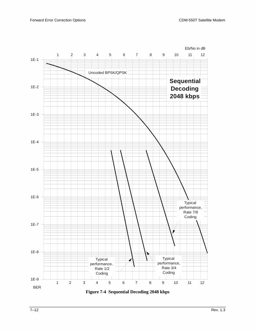
Forward Error Correction Options CDM-550T Satellite Modem
7–12 Rev. 1.3
Figure 7-4 Sequential Decoding 2048 kbps
1E-9
1E-8
1E-7
1E-6
1E-5
1E-4
1E-3
1E-2
1E-11 2 3 4 5 6 7 8 9 10 11 12
Eb/No in dB
Typicalperformance,
Rate 1/2Coding
Uncoded BPSK/QPSK
Typicalperformance,
Rate 3/4Coding
1 2 3 4 5 6 7 8 9 10 11 12
Typicalperformance,
Rate 7/8Coding
BER
SequentialDecoding2048 kbps
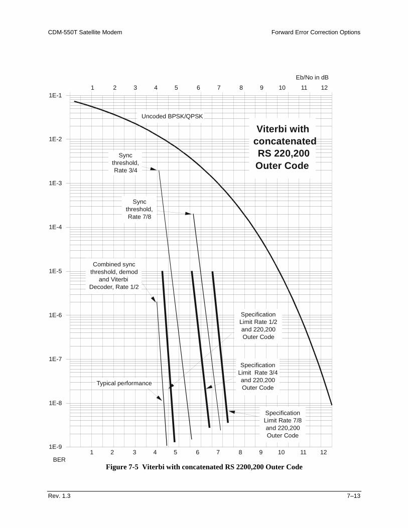
CDM-550T Satellite Modem Forward Error Correction Options
Rev. 1.3 7–13
Figure 7-5 Viterbi with concatenated RS 2200,200 Outer Code
1E-9
1E-8
1E-7
1E-6
1E-5
1E-4
1E-3
1E-2
1E-11 2 3 4 5 6 7 8 9 10 11 12
Eb/No in dB
SpecificationLimit Rate 1/2and 220,200Outer Code
Uncoded BPSK/QPSK
1 2 3 4 5 6 7 8 9 10 11 12BER
Viterbi withconcatenatedRS 220,200Outer Code
Combined syncthreshold, demod
and ViterbiDecoder, Rate 1/2
Syncthreshold,Rate 3/4
SpecificationLimit Rate 3/4and 220,200Outer Code
SpecificationLimit Rate 7/8and 220,200Outer Code
Syncthreshold,Rate 7/8
Typical performance
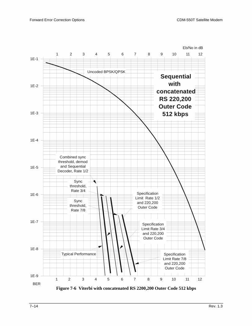
Forward Error Correction Options CDM-550T Satellite Modem
7–14 Rev. 1.3
Figure 7-6 Viterbi with concatenated RS 2200,200 Outer Code 512 kbps
1E-9
1E-8
1E-7
1E-6
1E-5
1E-4
1E-3
1E-2
1E-11 2 3 4 5 6 7 8 9 10 11 12
Eb/No in dB
SpecificationLimit Rate 1/2and 220,200Outer Code
Uncoded BPSK/QPSK
1 2 3 4 5 6 7 8 9 10 11 12BER
Sequentialwith
concatenatedRS 220,200Outer Code
512 kbps
Combined syncthreshold, demod
and SequentialDecoder, Rate 1/2
Syncthreshold,Rate 3/4
SpecificationLimit Rate 3/4and 220,200Outer Code
SpecificationLimit Rate 7/8and 220,200Outer Code
Syncthreshold,Rate 7/8
Typical Performance
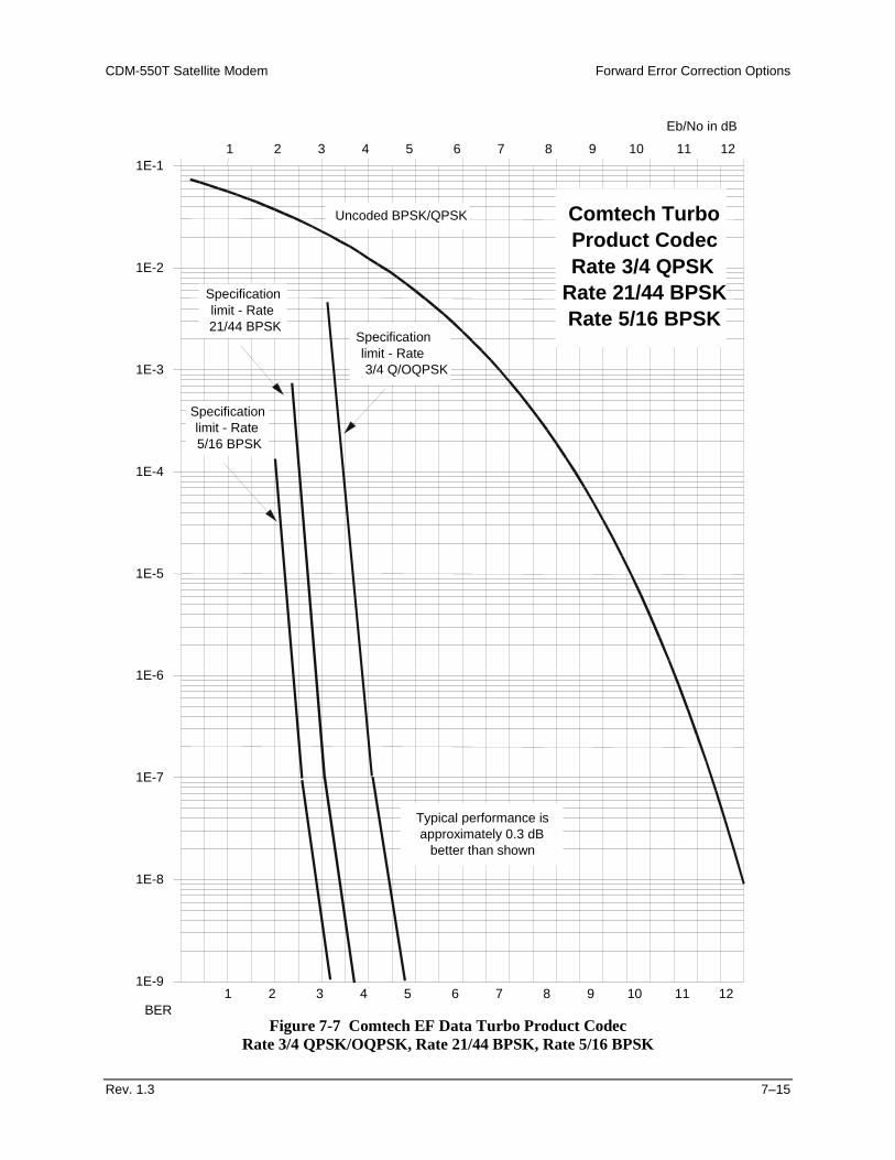
CDM-550T Satellite Modem Forward Error Correction Options
Rev. 1.3 7–15
Figure 7-7 Comtech EF Data Turbo Product Codec Rate 3/4 QPSK/OQPSK, Rate 21/44 BPSK, Rate 5/16 BPSK
1E-9
1E-8
1E-7
1E-6
1E-5
1E-4
1E-3
1E-2
1E-11 2 3 4 5 6 7 8 9 10 11 12
Eb/No in dB
Uncoded BPSK/QPSK Comtech TurboProduct CodecRate 3/4 QPSK
Rate 21/44 BPSKRate 5/16 BPSK
1 2 3 4 5 6 7 8 9 10 11 12BER
Specificationlimit - Rate3/4 Q/OQPSK
Typical performance isapproximately 0.3 dB
better than shown
Specificationlimit - Rate21/44 BPSK
Specificationlimit - Rate5/16 BPSK
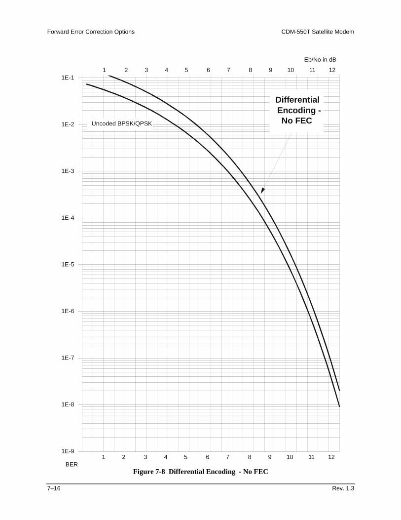
Forward Error Correction Options CDM-550T Satellite Modem
7–16 Rev. 1.3
Figure 7-8 Differential Encoding - No FEC
1E-9
1E-8
1E-7
1E-6
1E-5
1E-4
1E-3
1E-2
1E-11 2 3 4 5 6 7 8 9 10 11 12
Eb/No in dB
Uncoded BPSK/QPSK
DifferentialEncoding -No FEC
1 2 3 4 5 6 7 8 9 10 11 12BER
Rev. 1.3 8–1
8Chapter 8. OFFSET QPSK OPERATION
Offset QPSK modulation is a variation of normal QPSK, which is offered in the CDM-550T. Normal, bandlimited, QPSK produces an RF signal envelope which necessarily goes through a point of zero amplitude when the modulator transitions through non-adjacent phase states. This is not considered to be a problem in most communication systems, as long as the entire signal processing chain is linear. However, when bandlimited QPSK is passed through a non-linearity (for instance, a saturated power amplifier), there is a tendency for the carefully-filtered spectrum to degrade. This phenomenon is termed ‘spectral re-growth’, and at the extreme (hard limiting) the original, unfiltered sinx/x spectrum would result. In most systems, this would cause an unacceptable level of interference to adjacent carriers, and would cause degradation of the BER performance of the corresponding demodulator. To overcome the problem of the envelope collapsing to a point of zero amplitude, Offset QPSK places a delay between I and Q channels of exactly 1/2 symbol. Now the modulator cannot transition through zero when faced with non-adjacent phase states. The result is that there is far less variation in the envelope of the signal, and non-linearities do not cause the same level of degradation.
Offset Qpsk Operation CDM-550T Satellite Modem
8–2 Rev. 1.3
The demodulator must re-align the I and Q symbol streams before the process of carrier recovery can take place. For various reasons this makes the process of acquisition more difficult. The two consequences of this are: 1) Acquisition may be longer, especially at low data rates. 2) The acquisition threshold is higher than for normal QPSK, although the demodulator
will maintain lock down to its normal levels. The acquisition thresholds are as follows:
7.0 dB Eb/No for Rate 1/2 5.2 dB Eb/No for Rate 3/4 4.8 dB Eb/No for Rate 7/8 4.0 dB Eb/No for Uncoded operation (No FEC)
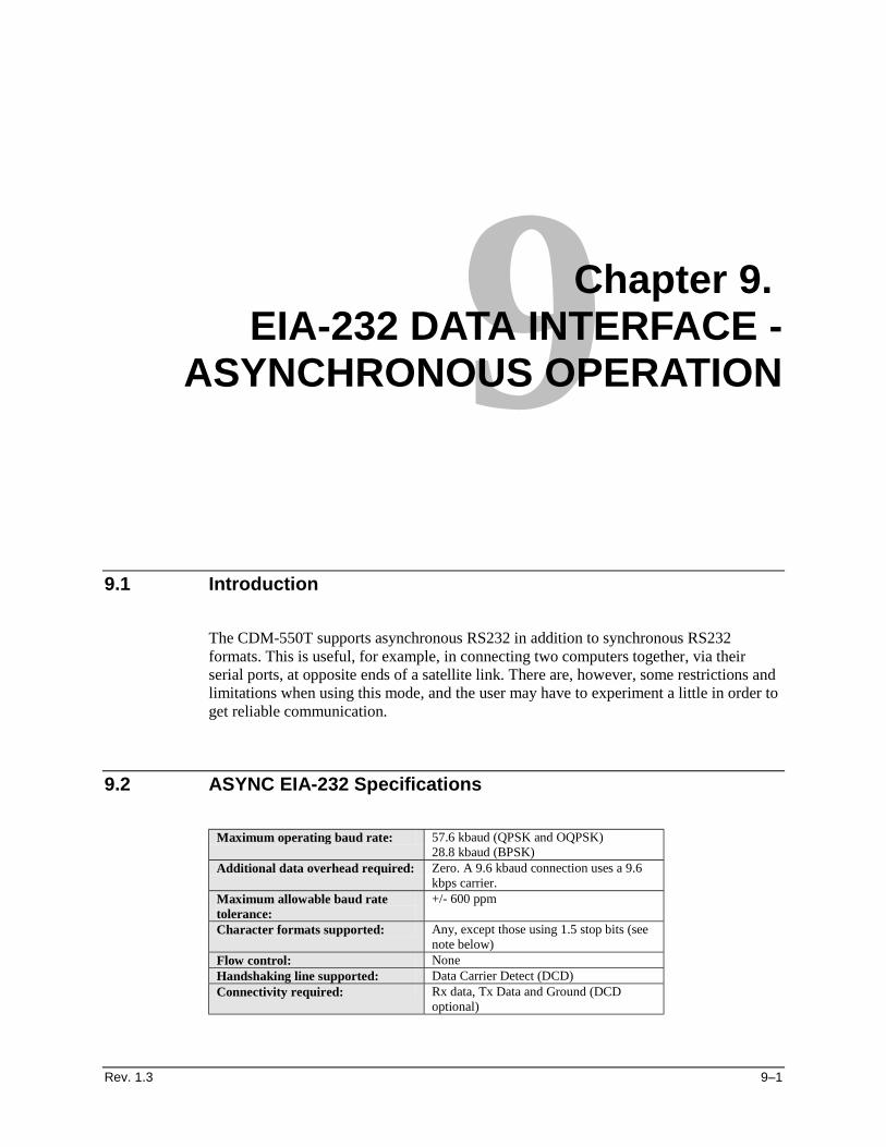
Rev. 1.3 9–1
9Chapter 9. EIA-232 DATA INTERFACE -
ASYNCHRONOUS OPERATION
9.1 Introduction
The CDM-550T supports asynchronous RS232 in addition to synchronous RS232 formats. This is useful, for example, in connecting two computers together, via their serial ports, at opposite ends of a satellite link. There are, however, some restrictions and limitations when using this mode, and the user may have to experiment a little in order to get reliable communication.
9.2 ASYNC EIA-232 Specifications
Maximum operating baud rate: 57.6 kbaud (QPSK and OQPSK)
28.8 kbaud (BPSK) Additional data overhead required: Zero. A 9.6 kbaud connection uses a 9.6
kbps carrier. Maximum allowable baud rate tolerance:
+/- 600 ppm
Character formats supported: Any, except those using 1.5 stop bits (see note below)
Flow control: None Handshaking line supported: Data Carrier Detect (DCD) Connectivity required: Rx data, Tx Data and Ground (DCD
optional)
EIA-232 Data Interface - Asynchronous Operation CDM-550T Satellite Modem
9–2 Rev. 1.3
9.3 Setup
The setup required for this mode is remarkably simple. Select RS232 as the interface type, and then select the required baud rate for both transmit and receive data rates. Detection of the asynchronous mode is fully automatic. If no clock is detected, asynchronous mode is assumed, and the internal circuitry is switched accordingly. The settings for both Tx and Rx clocking are irrelevant - the selected clocking options are ignored, and the internal clock circuitry is reconfigured for this ‘special’ mode.
9.4 Other Considerations
9.4.1 Baud Rate Accuracy
When connecting devices where the baud rate is not within the tolerance of +/- 600ppm, the Tx FIFO and Rx Buffer will occasionally underflow or overflow, causing characters to be lost. To avoid this, while the external device is connected, and transmitting data, connect a frequency counter to pin 15 of the rear panel Data Connector (the 25 pin ‘D’ type female). Measure the frequency, then set the transmit frequency to be equal to this value on the local modem, and set the receive frequency to this value at the other end of the link. If a frequency counter is not available, 10 minutes of trial and error will be an adequate substitute. Set the modem to an IF loop, and then try changing the baud rate by approximately 500 ppm at a time. At 9600 baud, this equates to either 9605 or 9595 baud, with further increments of 5 bps. If changing the baud rate in a positive direction results in more frequent buffer and/or FIFO slips, then move it in the opposite direction. Do this until the slips are eliminated.
9.4.2 Async Character Formats Using 1.5 Stop Bits
For situations where an async character format using 1.5 stop bits cannot be avoided, set the modem data rate to exactly twice the incoming baud rate. This uses twice as much bandwidth, but will permit this mode of operation.
Rev. 1.3 10–1
10 Chapter 10. CLOCKING
When dealing with satellite modems, the subject of clocking can be a complex issue. This section describes the various clocking options which are available with the CDM-550T.
10.1 Transmit Clocking
There are four transmit clocking modes in the CDM-550T. EIA-422/449 signal mnemonics will be used for illustration, but the description applies equally to V.35, and synchronous EIA-232.
10.1.1 Internal Clock
In this mode, the modem, assumed always to be the DCE, supplies the clock to the DTE. (The EIA-422/449 name for this signal is Send Timing, or ST.) The DTE then clocks from this source, and gives the modem transmit data (Send Data, or SD), synchronous with this clock. It is optional whether the DTE also returns the clock (Terminal Timing, or TT) - the modem can accept if it is present, but uses ST if is not.
10.1.2 External Clock
In this mode, the modem expects to see the DTE provide the clock, so that it can phase-lock its internal circuits. In this case, the modem does not provide any signal on ST, but instead requires a clock signal on Terminal Timing (TT), synchronous with the data. If no clock is present, an alarm will be generated.
Clocking CDM-550T Satellite Modem
10–2 Rev. 1.3
10.1.3 Loop-Timed, RX=TX
In certain circumstances, a terminal at the distant-end of a satellite link may be required to provide a clock to the DTE equipment which is locked to the receive satellite signal. This is similar to Internal Clock mode, in that the modem will source Send Timing (ST) to the DTE, but now the timing is derived from the demodulator. The DTE then clocks from this source, and gives the modem transmit data (Send Data, or SD), synchronous with this clock. It is optional whether the DTE also returns the clock (Terminal Timing, or TT) - the modem can accept if it is present, but uses ST if it is not. If the demodulator loses lock, the modem’s internal clock will be substituted, so an accurate and stable clock is present on ST, rather than a clock which may jitter and wander in a random fashion.
10.1.4 Loop-Timed, RX<>TX (Asymmetric Loop Timing)
The CDM-550T incorporates circuitry which permits loop timing when the TX and RX data rates are not the same. In this case the clock frequency appearing at ST will be whatever the TX data rate is programmed to, but phase-locked to the demodulator’s receive symbol clock. In all other respects the operation is the same as for ‘standard’ loop timing.
10.2 Receive Clocking
There are three receive clocking modes in the CDM-550T.
10.2.1 Buffer Disabled
When the buffer is disabled, the receive clock (Receive Timing, or RT) is derived directly from the demodulator, and hence will be subject to plesiochronous and Doppler offsets. In certain instances, this may be acceptable, and in the case of Loop Timing, it is essential that the buffer is disabled (which is done automatically).
10.2.2 Buffer Enabled, RX=TX
In this instance, it is required that buffer be enabled, so that the clock and data appearing on Receive Timing and Receive Data (RT and RD respectively) are synchronous with the transmit clock. This is a relatively simple case, as the output clock for the buffer is derived directly from either ST or TT.
CDM-550T Satellite Modem Clocking
Rev. 1.3 10–3
10.2.3 Buffer Enabled, RX<>TX
This is an uncommon case, where the receive and transmit data rates are not equal. The modem will generate a phase-locked buffer output clock which uses the transmit clock, regardless of its frequency in relation to the receive data rate.
10.3 X.21 Notes
For X.21 operation, use the RS422 pins, but ignore Receive Clock if the Modem is DTE, and ignore Transmit clocks if the Modem is DCE.
10.4 Loop Timing With Sync EIA-232
The CDM-550T distinguishes between synchronous and asynchronous EIA-232 by detecting clock activity on the TX Clock pin of the interface. If no clock is detected, it is assumed that the mode is asynchronous. Therefore, if loop timing is employed in a synchronous EIA-232 application, it is essential to provide an external loop between the ST and TX clock pins. If this is not done, the modem will assume an async mode, which is not compatible. The loop should be placed between pin 15 and pin 24 on the 25 pin ‘D’ type interface. THE FOLLOWING TWO PAGES ILLUSTRATE IN BLOCK-DIAGRAM FORM THE VARIOUS TRANSMIT AND RECEIVE CLOCK MODES.
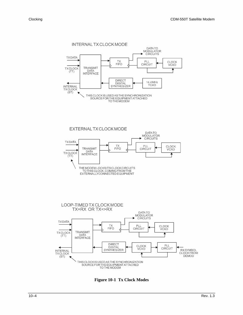
Clocking CDM-550T Satellite Modem
10–4 Rev. 1.3
Figure 10-1 Tx Clock Modes
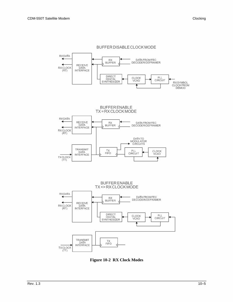
CDM-550T Satellite Modem Clocking
Rev. 1.3 10–5
Figure 10-2 RX Clock Modes

Clocking CDM-550T Satellite Modem
10–6 Rev. 1.3
This page has been intentionally left blank.
Rev. 1.3 11–1
11 Chapter 11. EDMAC CHANNEL
11.1 Theory Of Operation
As explained earlier, EDMAC is an acronym for Embedded Distant-end Monitor And Control. This is a feature which permits the user to access the M&C features of modems which are at the distant-end of a satellite link. This is accomplished by adding extra information to the user’s data, but in a manner which is completely transparent to the user. On the transmit side: The data is split into frames - each frame containing 1008 bits (except Rate 21/44 BPSK Turbo, where the frame length is 2928 bits, and Rate 5/16 BPSK Turbo where the frame length is 3072 bits). 48 bits in each frame are overhead, and the rest of these bits are the user’s data. This increases the rate of transmission by 5% (approximately 1.6% for the Turbo BPSK cases). For example, if the user’s data rate is 64 kbps, the actual transmission rate will now be at 67.2 kbps. At the start of each frame a 12 bit synchronization word is added. This allows the demodulator to find and lock to the start of frame. At regular intervals throughout the frame, additional data bytes and flag bits are added (a further 36 bits in total). It is these additional bytes which convey the M&C data. When framing is used, the normal V.35 scrambler is no longer used. This V.35 approach is called ‘self synchronizing’, because in the receiver, no external information is required in order for the de-scrambling process to recover the original data. The disadvantage of this method is that it multiplies errors. On average, if one bit error is present at the input
EDMAC Channel CDM-550T Satellite Modem
11–2 Rev. 1.3
of the descrambler, 3 output errors are generated. However, there is an alternative when the data is in a framed format. In this case, a different class of scrambler may be used - one which uses the start of frame information to start the scrambling process at an exact known state. In the receiver, having synchronised to the frame, the de-scrambler can begin its processing at exactly the right time. This method does not multiply errors, and therefore has a clear advantage over V.35 scrambling. This is fortunate, as there is a penalty to be paid for adding the framing. By adding the extra 5% to the transmitted data rate, the effective Eb/No seen by the user will degrade by a factor of 10log(1.05), or 0.21 dB (0.07dB in the case of the two BPSK Turbo rates). The use of an externally synchronized scrambler and descrambler almost exactly compensates for this degradation. The net effect is that the user will see effectively identical BER performance whether framing is used or not. On the receive side: When the demodulator locks to the incoming carrier, it must go through the additional step of searching for, and locking to the synchronization word. This uniquely identifies the start of frame, and permits the extraction of the overhead bytes and flag bits at the correct position within the frame. In addition, the start of frame permits the de-scrambler to correctly recover the data. The user’s data is extracted, and sent through additional processing, in the normal manner. The extracted overhead bytes are examined to determine if they contain valid M&C bytes.
11.2 M&C Connection
Data to be transmitted to the distant-end is sent to a local unit via the remote control port. A message for the distant-end is indistinguishable from a ‘local’ message - it has the same structure and content, only the address will identify it as being for a distant-end unit. Before the M&C data can be successfully transmitted and received, pairs of units must be split into EDMAC Masters and EDMAC Slaves. Masters are local to the M&C Computer, and Slaves are distant-end. Now, a unit which has been designated an EDMAC master not only responds to its own unique bus address, but it will also be configured to listen for the address which corresponds to its EDMAC Slave. When a complete message packet has be received by the EDMAC Master, it will begin to transmit this packet over the satellite channel, using the overhead bytes which become available. (Note: The ‘normal’ protocol for the message packet is not used over the satellite path, as it is subject to errors. For this reason, a much more robust protocol is used which incorporates extensive error checking.) At the distant-end, the EDMAC slave, configured for the correct address, receives these bytes, and when a complete packet has been received, it will take the action requested, and then send the appropriate response to the EDMAC Master, using the return overhead
CDM-550T Satellite Modem EDMAC Channel
Rev. 1.3 11–3
path on the satellite link. The EDMAC Master assembles the complete packet, and transmits the response back to the M&C Computer. Apart from the round-trip satellite delay, the M&C Computer does not see any difference between local and distant-end units - it sends out a packet, addressed to a particular unit, and gets back a response. It can be seen that the EDMAC Master simply acts as forwarding service, in a manner which is completely transparent. This approach does not require any additional cabling - connection is made using the normal M&C remote port. Furthermore, the user does not have to worry about configuring the baud rate of the M&C connection to match the lowest data rate modem in the system. The M&C system can have mixed data-rate modems, from 2.4 kbps to 2048 kbps, and still run at speeds in excess of 19,200 baud. It should be pointed out that at 2.4 kbps, the effective throughput of the overhead channel is only 11 async characters/second. For a message of 24 bytes, the time between sending a poll request and receiving a response will be around 5 seconds. (Note that when either of the BPSK Turbo rates are in use, the overhead rate is reduced by a factor of three, and therfore the response time will be sround 15 seconds.)
11.3 Setup Summary
To access a distant-end unit:
Designate a Master/Slave pair - Master at the local-end, Slave at the distant-end.
On the local-end unit, enable framing, and EDMAC, define the unit as MASTER, then enter the bus address of the SLAVE. This is constrained to be ‘base 10' meaning that only addresses such as 10, 20, 30, 40 etc, are allowed.
Choose a unique bus address for the distant-end. This should normally be set to
the ‘base 10' address + 1. For example, if the MASTER unit is set to 30, choose 31 for the distant-end unit.
On the distant-end unit, enable framing, and EDMAC, define the unit as SLAVE,
then enter the bus address. The orange EDMAC Mode LED should be illuminated.
Set the local-end unit to RS485 remote control, and set the bus address of this
local unit. The orange Remote Mode LED should be illuminated.
Once the satellite link has been established, connect the M&C Computer, and begin communications, with both the local and distant end units.
NOTE: EDMAC modes are fully compatible with AUPC modes.

EDMAC Channel CDM-550T Satellite Modem
11–4 Rev. 1.3
This page has been intentionally left blank.
Rev. 1.3 12–1
12 Chapter 12. AUTOMATIC UPLINK
POWER CONTROL
12.1 Introduction
Automatic Uplink Power Control (AUPC) is a feature whereby a local modem is permitted to adjust its own output power level in order to attempt to maintain the Eb/No at the remote modem.
To accomplish this, the framed (EDMAC) mode of operation must be used. The remote modem constantly sends back information about the demodulator Eb/No using reserved bytes in the overhead structure. The local modem then compares this value of Eb/No with a pre-defined target value. If the Remote Eb/No is below the target, the local modem will increase its output power, and hence, a closed-loop feedback system is created over the satellite link. A particularly attractive benefit of this feature is that whenever framed operation is selected, the remote demodulator’s Eb/No can be viewed from the front panel display of the local modem. Note also that AUPC can be used simultaneously with EDMAC. There are several important parameters associated with this mode of operation, and the user needs to understand how the AUPC feature works, and the implications of setting these parameters.
! ! ! IMPORTANT WARNING ! ! ! The user MUST obtain permission from the Satellite Operator to use this feature.
Improper use of this feature could result in a transmitting terminal seriously exceeding its allocated flux density on the Operator’s satellite. This could produce interference to other
carriers, and could cause transponder saturation problems
Automatic Uplink Power Control (AUPC) CDM-550T Satellite Modem
12–2 Rev. 1.3
12.2 Setting AUPC Parameters
1) The user, under the menu (CONFIG, FRAME) first ensures that Framed mode is selected. EDMAC may be disabled, or the unit may be defined as an EDMAC Master or Slave. The important consideration is that Framing should be enabled.
2) The user should verify that the remote modem also has Framing enabled.
3) The user, under the menu (CONFIG, TX, PWR) sets the nominal output power of
the modem. This is done by selecting the MANUAL mode, then editing the TX output power level displayed.
4) The user will then select AUPC as the operating mode. At this point the user will
be prompted to define four key parameters:
12.2.1 Target Eb/No
This is value of Eb/No that the user desires to keep constant at the remote modem. If the Eb/No exceeds this value, the AUPC control will reduce the TX output power, but will never drop below the nominal value set. If the Eb/No falls below this value, the AUPC control will increase the TX output power, but will never exceed the value determined by the parameter MAX RANGE. The minimum value the user can enter is 0.0 dB The maximum value the user can enter is 9.9 dB The default value is 3.0 dB The resolution is 0.1 dB
12.2.2 Max Range
This defines how much the modem is permitted to increase the output level, under AUPC control. The minimum value the user can enter is 0 dB The maximum value the user can enter is 9 dB The default value is 1 dB The resolution is 1 dB
CDM-550T Satellite Modem Automatic Uplink Power Control (AUPC)
Rev. 1.3 12–3
12.2.3 Alarm
This parameter defines how the user wants the modem to act if, under AUPC control, the maximum power limit is reached. The two choices are: NONE (no action) TX ALARM (generate a TX alarm) The default setting is NONE.
12.2.4 Demod Unlock
This defines the action the modem will take if the remote demodulator loses lock. The two choices are: NOMINAL (reduce the TX Output Power to the nominal value) MAXIMUM (increase the TX Output Power to the maximum value permitted by the parameter MAX RANGE) The default setting is NOMINAL. (Note that if the local demod loses lock, the modem will automatically move its output power to the nominal value.)
12.3 Compensation Rate
As with any closed-loop control system, the loop parameters must be chosen to ensure stability at all times. Several features have been incorporated to ensure that the AUPC system does overshoot, or oscillate. First, the rate at which corrections to the output power can be made is fixed at once every 4 seconds. This takes into account the round trip delay over the satellite link, the time taken for a power change to be reflected in the remote demodulator’s value of Eb/No, and other processing delays in the modems. Second, if the comparison of actual and target Eb/No yields a result that requires a change in output power, the first correction made will be 80% of the calculated step. This avoids the possibility of overshoot. Subsequent corrections are made until the difference is less than 0.5 dB. At this point, the output power is only changed in increments of 0.1 dB, to avoid ‘hunting’ around the correct set point.
Automatic Uplink Power Control (AUPC) CDM-550T Satellite Modem
12–4 Rev. 1.3
12.4 Monitoring
The remote demodulator’s value of Eb/No can be monitored at all times, either from the front panel (MONIT, AUPC) or via the remote control interface. The resolution of the reading is 0.2 dB. For all values greater than or equal to 16 dB, the value 16.0 dB will be displayed. As long as framing is enabled, the value will still be available, even though AUPC may be disabled. Also displayed is the current value of TX power increase. If Framing is enabled, but AUPC is disabled, this will indicate 0.0 dB. This value is also available via the remote control interface.
CAUTION Comtech EFData strongly cautions against the use of large values of
permitted power level increase under AUPC control. Users should consider using the absolute minimum range necessary to improve rain-fade margin
Rev. 1.3 13–1
13 Chapter 13. FLASH UPGRADING
The CDM-550T eliminates the need for updating firmware by physically replacing EPROMs. Instead, the CDM-550T modem uses ‘flash memory’ technology internally, and new firmware can be uploaded to the unit from an external PC. This makes software upgrading very simple, and updates can now be sent via the Internet, E-mail, or on disk. The upgrade can be performed without opening the unit, by simply connecting the modem to the serial port of a computer. The cable to connect the PC to the modem is the same as is used for normal EIA-232 remote control, and comprises 3-wires between 9 pin ‘D’ type female connectors. This is shown in Appendix A. Comtech EFData will distribute a free software utility, that is designed to run under Windows 3.1x, Windows 95/98 or Windows NT. This utility program is called CCCFlash.exe, and should be copied to the user’s computer hard disk. Along with this, the user will receive the latest firmware file (for example, 550TV102.ccc), which the user should copy to the same sub-directory (folder). The user then connects the modem remote control port to an unused serial port on the user’s computer, and executes the program. The user should follow the instructions presented on the screen, and the upload will take place automatically. Following the successful upload process, the modem will automatically re-start, running the new version of firmware. During this process, the non-volatile RAM, storing the configuration of the modem, will be erased, so the user is then required to re-enter the desired configuration parameters. Full on-line help is provided with CCCFlash.exe, but if users experience a problem, or have a question, they should contact Comtech EFData Technical Support.

Flash Upgrading CDM-550T Satellite Modem
13–2 Rev. 1.3
This page is intentionally blank.
Rev. 1.3 14–1
14 Chapter 14. SUMMARY OF
SPECIFICATIONS
14.1 MODULATOR Modulation BPSK, QPSK, and Offset QPSK Data rate range Overall, 2.4 - 2048 kbps
4.8 kbps - 2048 kbps, Uncoded BPSK 9.6 kbps - 2048 kbps, Uncoded QPSK/OQPSK 2.4 kbps - 1024 kbps, Rate 1/2 BPSK 4.8 kbps - 2048 kbps, Rate 1/2 QPSK/OQPSK 7.2 kbps - 2048 kbps, Rate 3/4 QPSK/OQPSK 8.4 kbps - 2048 kbps, Rate 7/8 QPSK/OQPSK 2.4 kbps - 1145 kbps, Rate 21/44 BPSK Turbo 2.4 kbps - 750 kbps, Rate 5/16 BPSK Turbo
Operating modes Transparent, Closed Network Proprietary EDMAC framed mode: * 5% overhead addition - all modes except BPSK Turbo * 1.5% overhead addition - Rate 21/44 and 5/16 Turbo RS Outer Codec (optional) Turbo Product Codec (optional): * Rate 3/4 QPSK/OQPSK * Rate 21/44 BPSK * Rate 5/16 BPSK Automatic Uplink Power Contol (AUPC) mode
Transmit filtering Per INTELSAT IESS 308 (64 to 512 tap FIR digital filter implementation) Scrambling Transparent mode, no RS coding - per CCITT V.35
EDMAC mode, no RS coding - externally synchronized Turbo Product Code mode - externally synchronized All RS modes - externally synchronized per IESS 308
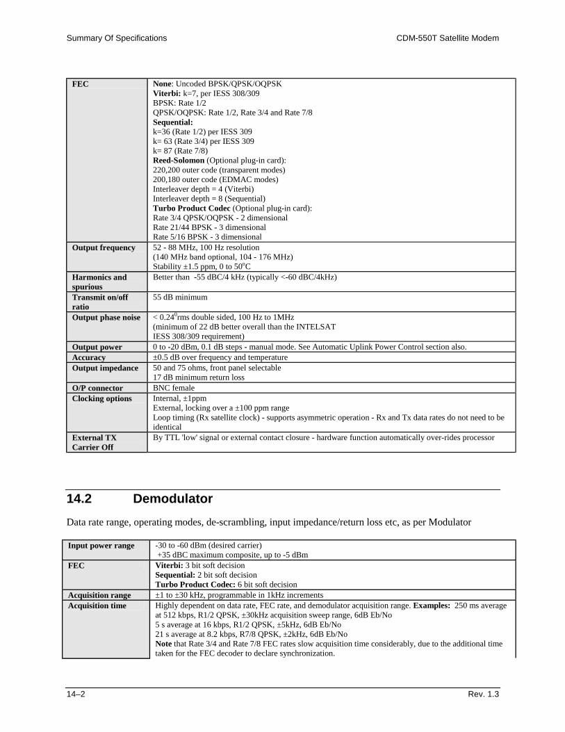
Summary Of Specifications CDM-550T Satellite Modem
14–2 Rev. 1.3
FEC None: Uncoded BPSK/QPSK/OQPSK
Viterbi: k=7, per IESS 308/309 BPSK: Rate 1/2 QPSK/OQPSK: Rate 1/2, Rate 3/4 and Rate 7/8 Sequential: k=36 (Rate 1/2) per IESS 309 k= 63 (Rate 3/4) per IESS 309 k= 87 (Rate 7/8) Reed-Solomon (Optional plug-in card): 220,200 outer code (transparent modes) 200,180 outer code (EDMAC modes) Interleaver depth = 4 (Viterbi) Interleaver depth = 8 (Sequential) Turbo Product Codec (Optional plug-in card): Rate 3/4 QPSK/OQPSK - 2 dimensional Rate 21/44 BPSK - 3 dimensional Rate 5/16 BPSK - 3 dimensional
Output frequency 52 - 88 MHz, 100 Hz resolution (140 MHz band optional, 104 - 176 MHz) Stability ±1.5 ppm, 0 to 50oC
Harmonics and spurious
Better than -55 dBC/4 kHz (typically <-60 dBC/4kHz)
Transmit on/off ratio
55 dB minimum
Output phase noise < 0.240rms double sided, 100 Hz to 1MHz (minimum of 22 dB better overall than the INTELSAT IESS 308/309 requirement)
Output power 0 to -20 dBm, 0.1 dB steps - manual mode. See Automatic Uplink Power Control section also. Accuracy ±0.5 dB over frequency and temperature Output impedance 50 and 75 ohms, front panel selectable
17 dB minimum return loss O/P connector BNC female Clocking options Internal, ±1ppm
External, locking over a ±100 ppm range Loop timing (Rx satellite clock) - supports asymmetric operation - Rx and Tx data rates do not need to be identical
External TX Carrier Off
By TTL 'low' signal or external contact closure - hardware function automatically over-rides processor
14.2 Demodulator Data rate range, operating modes, de-scrambling, input impedance/return loss etc, as per Modulator Input power range -30 to -60 dBm (desired carrier)
+35 dBC maximum composite, up to -5 dBm FEC Viterbi: 3 bit soft decision
Sequential: 2 bit soft decision Turbo Product Codec: 6 bit soft decision
Acquisition range ±1 to ±30 kHz, programmable in 1kHz increments Acquisition time Highly dependent on data rate, FEC rate, and demodulator acquisition range. Examples: 250 ms average
at 512 kbps, R1/2 QPSK, ±30kHz acquisition sweep range, 6dB Eb/No 5 s average at 16 kbps, R1/2 QPSK, ±5kHz, 6dB Eb/No 21 s average at 8.2 kbps, R7/8 QPSK, ±2kHz, 6dB Eb/No Note that Rate 3/4 and Rate 7/8 FEC rates slow acquisition time considerably, due to the additional time taken for the FEC decoder to declare synchronization.
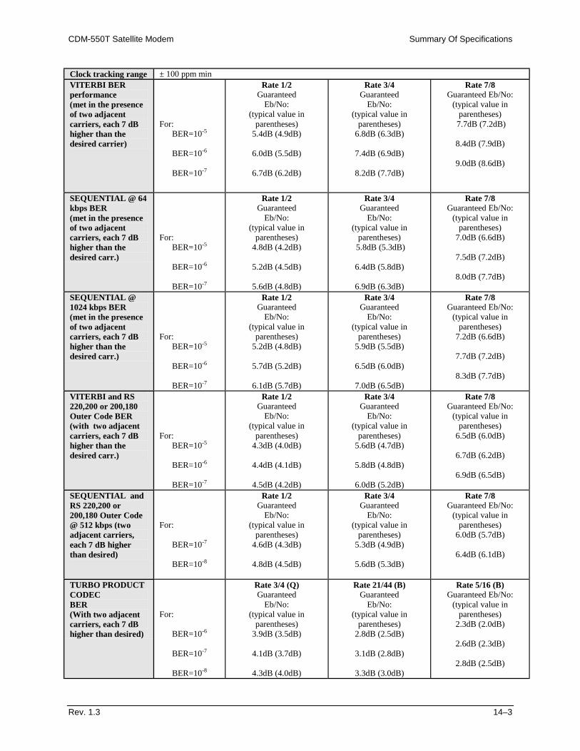
CDM-550T Satellite Modem Summary Of Specifications
Rev. 1.3 14–3
Clock tracking range ± 100 ppm min VITERBI BER performance (met in the presence of two adjacent carriers, each 7 dB higher than the desired carrier)
For:
BER=10-5
BER=10-6
BER=10-7
Rate 1/2 Guaranteed
Eb/No: (typical value in
parentheses) 5.4dB (4.9dB)
6.0dB (5.5dB)
6.7dB (6.2dB)
Rate 3/4 Guaranteed
Eb/No: (typical value in
parentheses) 6.8dB (6.3dB)
7.4dB (6.9dB)
8.2dB (7.7dB)
Rate 7/8 Guaranteed Eb/No:
(typical value in parentheses)
7.7dB (7.2dB)
8.4dB (7.9dB)
9.0dB (8.6dB)
SEQUENTIAL @ 64 kbps BER (met in the presence of two adjacent carriers, each 7 dB higher than the desired carr.)
For:
BER=10-5
BER=10-6
BER=10-7
Rate 1/2 Guaranteed
Eb/No: (typical value in
parentheses) 4.8dB (4.2dB)
5.2dB (4.5dB)
5.6dB (4.8dB)
Rate 3/4 Guaranteed
Eb/No: (typical value in
parentheses) 5.8dB (5.3dB)
6.4dB (5.8dB)
6.9dB (6.3dB)
Rate 7/8 Guaranteed Eb/No:
(typical value in parentheses)
7.0dB (6.6dB)
7.5dB (7.2dB)
8.0dB (7.7dB)
SEQUENTIAL @ 1024 kbps BER (met in the presence of two adjacent carriers, each 7 dB higher than the desired carr.)
For:
BER=10-5
BER=10-6
BER=10-7
Rate 1/2 Guaranteed
Eb/No: (typical value in
parentheses) 5.2dB (4.8dB)
5.7dB (5.2dB)
6.1dB (5.7dB)
Rate 3/4 Guaranteed
Eb/No: (typical value in
parentheses) 5.9dB (5.5dB)
6.5dB (6.0dB)
7.0dB (6.5dB)
Rate 7/8 Guaranteed Eb/No:
(typical value in parentheses)
7.2dB (6.6dB)
7.7dB (7.2dB)
8.3dB (7.7dB)
VITERBI and RS 220,200 or 200,180 Outer Code BER (with two adjacent carriers, each 7 dB higher than the desired carr.)
For:
BER=10-5
BER=10-6
BER=10-7
Rate 1/2 Guaranteed
Eb/No: (typical value in
parentheses) 4.3dB (4.0dB)
4.4dB (4.1dB)
4.5dB (4.2dB)
Rate 3/4 Guaranteed
Eb/No: (typical value in
parentheses) 5.6dB (4.7dB)
5.8dB (4.8dB)
6.0dB (5.2dB)
Rate 7/8 Guaranteed Eb/No:
(typical value in parentheses)
6.5dB (6.0dB)
6.7dB (6.2dB)
6.9dB (6.5dB)
SEQUENTIAL and RS 220,200 or 200,180 Outer Code @ 512 kbps (two adjacent carriers, each 7 dB higher than desired)
For:
BER=10-7
BER=10-8
Rate 1/2 Guaranteed
Eb/No: (typical value in
parentheses) 4.6dB (4.3dB)
4.8dB (4.5dB)
Rate 3/4 Guaranteed
Eb/No: (typical value in
parentheses) 5.3dB (4.9dB)
5.6dB (5.3dB)
Rate 7/8 Guaranteed Eb/No:
(typical value in parentheses)
6.0dB (5.7dB)
6.4dB (6.1dB)
TURBO PRODUCT CODEC BER (With two adjacent carriers, each 7 dB higher than desired)
For:
BER=10-6
BER=10-7
BER=10-8
Rate 3/4 (Q) Guaranteed
Eb/No: (typical value in
parentheses) 3.9dB (3.5dB)
4.1dB (3.7dB)
4.3dB (4.0dB)
Rate 21/44 (B) Guaranteed
Eb/No: (typical value in
parentheses) 2.8dB (2.5dB)
3.1dB (2.8dB)
3.3dB (3.0dB)
Rate 5/16 (B) Guaranteed Eb/No:
(typical value in parentheses)
2.3dB (2.0dB)
2.6dB (2.3dB)
2.8dB (2.5dB)
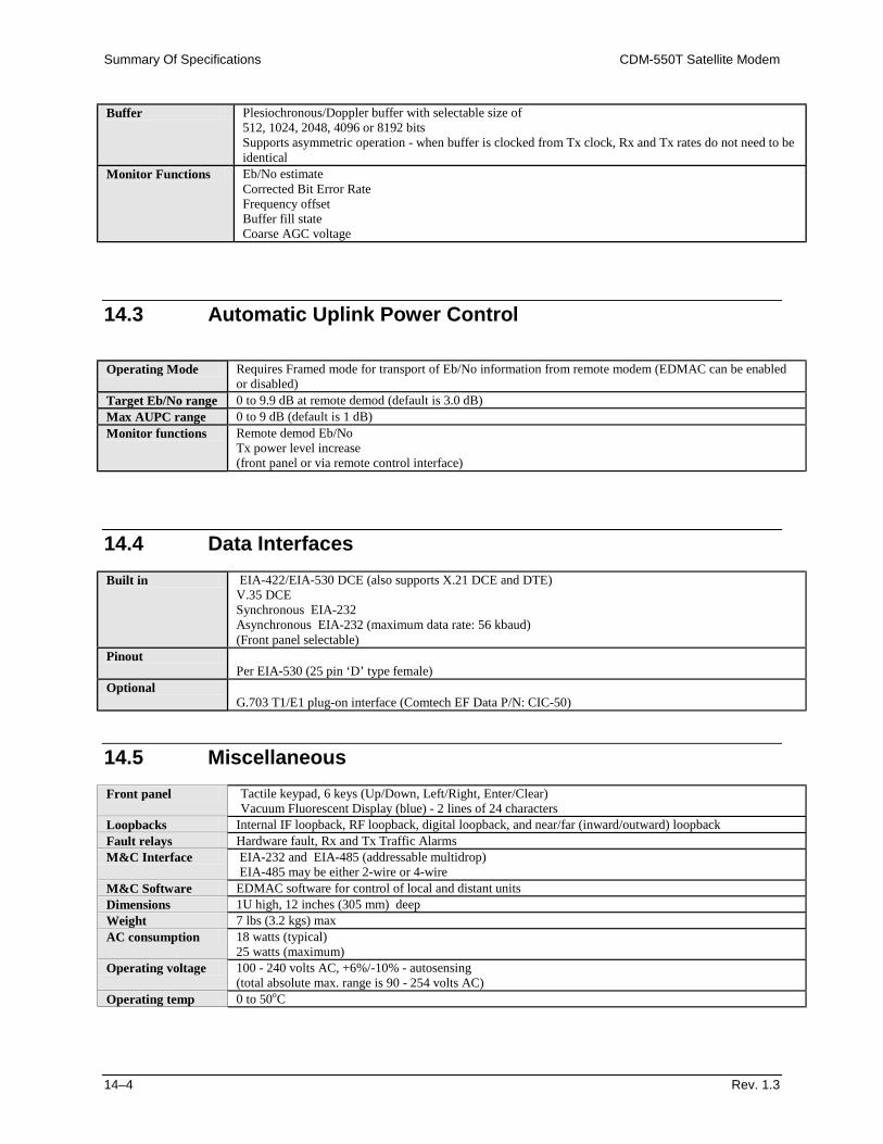
Summary Of Specifications CDM-550T Satellite Modem
14–4 Rev. 1.3
Buffer Plesiochronous/Doppler buffer with selectable size of 512, 1024, 2048, 4096 or 8192 bits Supports asymmetric operation - when buffer is clocked from Tx clock, Rx and Tx rates do not need to be identical
Monitor Functions Eb/No estimate Corrected Bit Error Rate Frequency offset Buffer fill state Coarse AGC voltage
14.3 Automatic Uplink Power Control
Operating Mode Requires Framed mode for transport of Eb/No information from remote modem (EDMAC can be enabled or disabled)
Target Eb/No range 0 to 9.9 dB at remote demod (default is 3.0 dB) Max AUPC range 0 to 9 dB (default is 1 dB) Monitor functions Remote demod Eb/No
Tx power level increase (front panel or via remote control interface)
14.4 Data Interfaces Built in EIA-422/EIA-530 DCE (also supports X.21 DCE and DTE)
V.35 DCE Synchronous EIA-232 Asynchronous EIA-232 (maximum data rate: 56 kbaud) (Front panel selectable)
Pinout Per EIA-530 (25 pin ‘D’ type female)
Optional G.703 T1/E1 plug-on interface (Comtech EF Data P/N: CIC-50)
14.5 Miscellaneous Front panel Tactile keypad, 6 keys (Up/Down, Left/Right, Enter/Clear)
Vacuum Fluorescent Display (blue) - 2 lines of 24 characters Loopbacks Internal IF loopback, RF loopback, digital loopback, and near/far (inward/outward) loopback Fault relays Hardware fault, Rx and Tx Traffic Alarms M&C Interface EIA-232 and EIA-485 (addressable multidrop)
EIA-485 may be either 2-wire or 4-wire M&C Software EDMAC software for control of local and distant units Dimensions 1U high, 12 inches (305 mm) deep Weight 7 lbs (3.2 kgs) max AC consumption 18 watts (typical)
25 watts (maximum) Operating voltage 100 - 240 volts AC, +6%/-10% - autosensing
(total absolute max. range is 90 - 254 volts AC) Operating temp 0 to 50oC
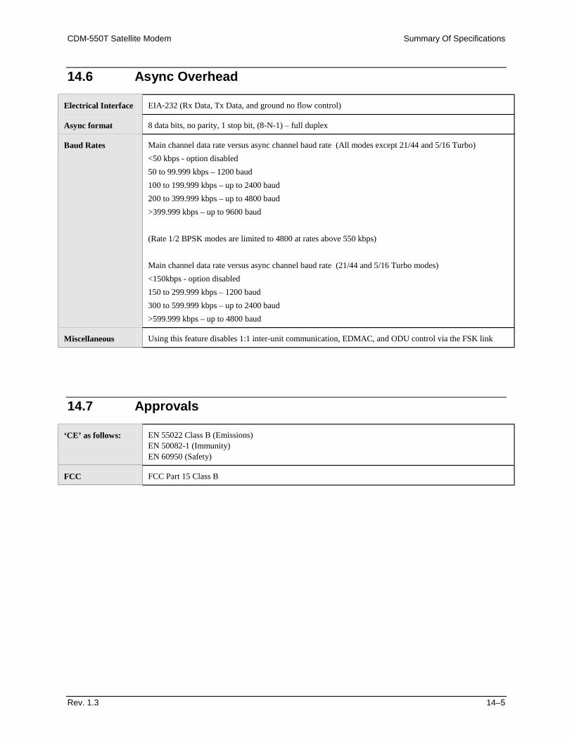
CDM-550T Satellite Modem Summary Of Specifications
Rev. 1.3 14–5
14.6 Async Overhead Electrical Interface
EIA-232 (Rx Data, Tx Data, and ground no flow control)
Async format
8 data bits, no parity, 1 stop bit, (8-N-1) – full duplex
Baud Rates
Main channel data rate versus async channel baud rate (All modes except 21/44 and 5/16 Turbo) <50 kbps - option disabled 50 to 99.999 kbps – 1200 baud 100 to 199.999 kbps – up to 2400 baud 200 to 399.999 kbps – up to 4800 baud >399.999 kbps – up to 9600 baud (Rate 1/2 BPSK modes are limited to 4800 at rates above 550 kbps) Main channel data rate versus async channel baud rate (21/44 and 5/16 Turbo modes) <150kbps - option disabled 150 to 299.999 kbps – 1200 baud 300 to 599.999 kbps – up to 2400 baud >599.999 kbps – up to 4800 baud
Miscellaneous
Using this feature disables 1:1 inter-unit communication, EDMAC, and ODU control via the FSK link
14.7 Approvals ‘CE’ as follows:
EN 55022 Class B (Emissions) EN 50082-1 (Immunity) EN 60950 (Safety)
FCC
FCC Part 15 Class B
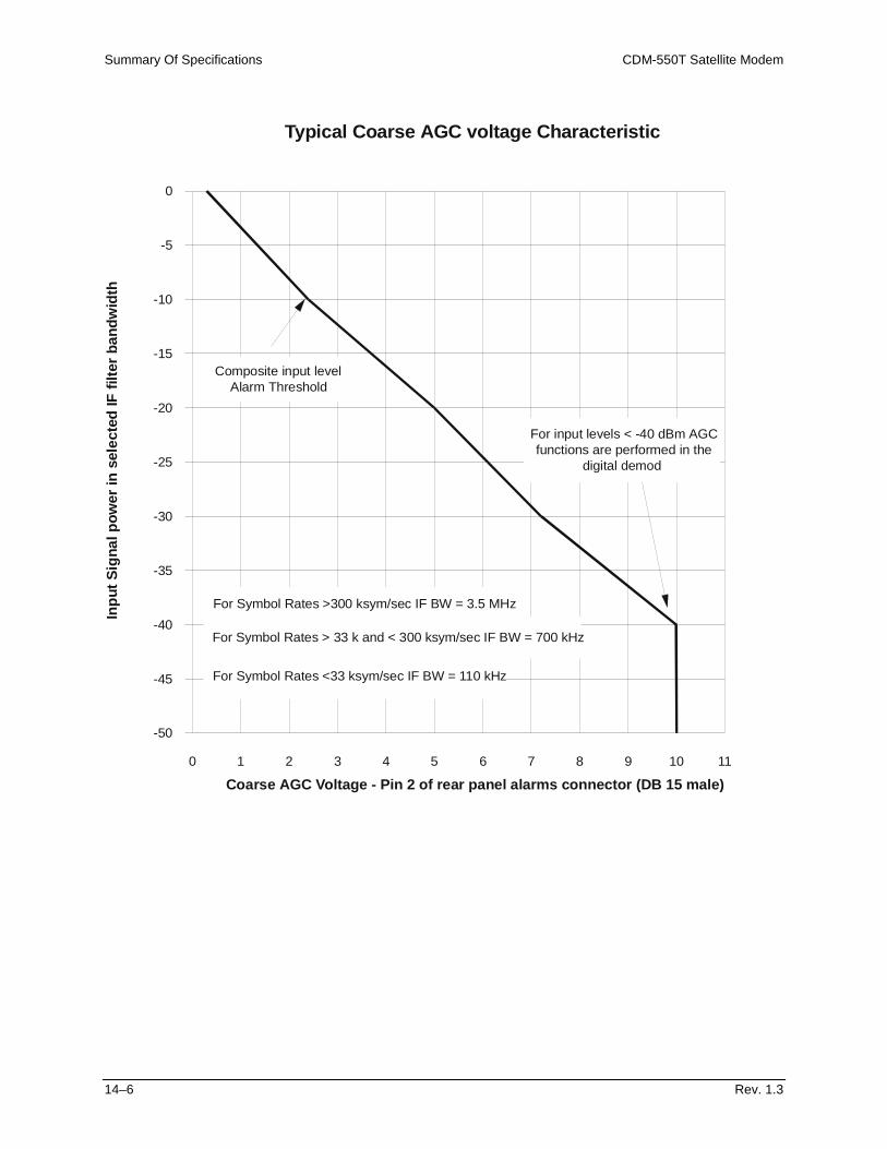
Summary Of Specifications CDM-550T Satellite Modem
14–6 Rev. 1.3
Typical Coarse AGC voltage Characteristic
Coarse AGC Voltage - Pin 2 of rear panel alarms connector (DB 15 male)
Inpu
tSig
nalp
ower
inse
lect
edIF
filte
rban
dwid
th
-50
-45
-40
-35
-30
-25
-20
-15
-10
-5
0
0 1 2 3 4 5 6 7 8 9 10 11
For Symbol Rates >300 ksym/sec IF BW = 3.5 MHz
For Symbol Rates <33 ksym/sec IF BW = 110 kHz
For Symbol Rates > 33 k and < 300 ksym/sec IF BW = 700 kHz
Composite input levelAlarm Threshold
For input levels < -40 dBm AGCfunctions are performed in the
digital demod
Rev. 1.3 15–1
15 Chapter 15. REMOTE CONTROL
15.1 Introduction
This section describes the protocol and message command set for remote monitor and control of the CDM-550 Modem. The electrical interface is either an EIA-485 multi-drop bus (for the control of many devices) or an EIA-232 connection (for the control of a single device), and data is transmitted in asynchronous serial form, using ASCII characters. Control and status information is transmitted in packets, of variable length, in accordance with the structure and protocol defined in later sections.
15.2 EIA-485
For applications where multiple devices are to be monitored and controlled, a full-duplex (or 4-wire) EIA-485 is preferred. Half-duplex (2-wire) EIA-485 is possible, but is not preferred. In full-duplex EIA-485 communication there are two separate, isolated, independent, differential-mode twisted pairs, each handling serial data in different directions. It is assumed that there is a ‘controller’ device (a PC or dumb terminal), which transmits data, in a broadcast mode, via one of the pairs. Many ‘target’ devices are connected to this pair, which all simultaneously receive data from the controller. The controller is the only device with a line-driver connected to this pair - the target devices only have line-receivers connected.
Remote Control CDM-550T Satellite Modem
15–2 Rev. 1.3
In the other direction, on the other pair, each target has a tri-stateable line driver connected, and the controller has a line-receiver connected. All the line drivers are held in high-impedance mode until one (and only one) target transmits back to the controller. Each target has a unique address, and each time the controller transmits, in a framed ‘packet’ of data, the address of the intended recipient target is included. All of the targets receive the packet, but only one (the intended) will reply. The target enables its output line driver, and transmits its return data packet back to the controller, in the other direction, on the physically separate pair. EIA 485 (full duplex) summary:
• Two differential pairs - one pair for controller to target, one pair for target to controller.
• Controller-to-target pair has one line driver (controller), and all targets have line-receivers.
• Target-to-controller pair has one line receiver (controller), and all targets have tri-state drivers.
15.3 EIA-232
This a much simpler configuration in which the controller device is connected directly to the target via a two-wire-plus-ground connection. Controller-to-target data is carried, via EIA-232 electrical levels, on one conductor, and target-to-controller data is carried in the other direction on the other conductor.
15.4 Basic Protocol
Whether in EIA-232 or EIA-485 mode, all data is transmitted as asynchronous serial characters, suitable for transmission and reception by a UART. In this case, the asynchronous character format is fixed at 8 data bits, one stop bit, no parity. The baud rate may vary between 50 baud and 19,200 baud. All data is transmitted in framed packets. The controller is assumed to be a PC or ASCII dumb terminal, which is in charge of the process of monitor and control. The controller is the only device which is permitted to initiate, at will, the transmission of data. Targets are only permitted to transmit when they have been specifically instructed to do so by the controller. All bytes within a packet are printable ASCII characters, less than ASCII code 127. In this context, the Carriage Return and Line Feed characters are considered printable. All messages from controller to target require a response (with one exception). This will be either to return data which has been requested by the controller, or to acknowledge reception of an instruction to change the configuration of the target. The exception to this is when the controller broadcasts a message (such as Set time/date) using Address 0, when the target is set to EIA-485 mode.
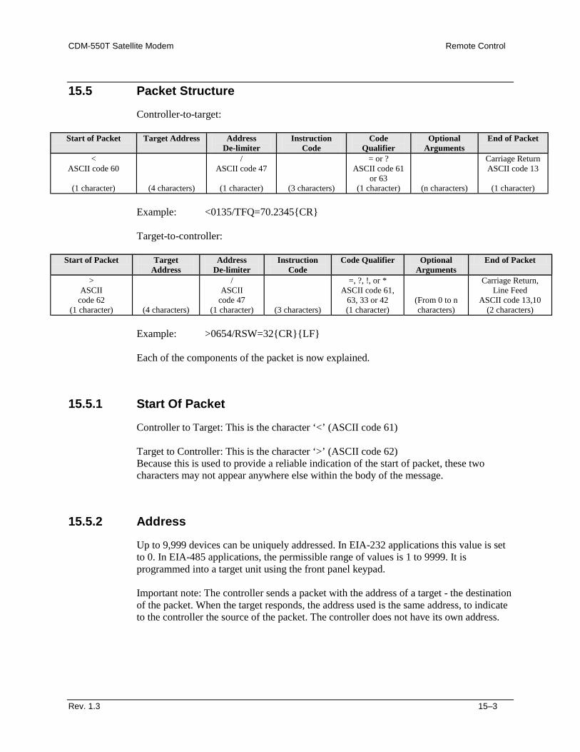
CDM-550T Satellite Modem Remote Control
Rev. 1.3 15–3
15.5 Packet Structure
Controller-to-target:
Start of Packet Target Address Address De-limiter
Instruction Code
Code Qualifier
Optional Arguments
End of Packet
< ASCII code 60
(1 character)
(4 characters)
/ ASCII code 47
(1 character)
(3 characters)
= or ? ASCII code 61
or 63 (1 character)
(n characters)
Carriage Return ASCII code 13
(1 character)
Example: <0135/TFQ=70.2345{CR} Target-to-controller:
Start of Packet Target Address
Address De-limiter
Instruction Code
Code Qualifier Optional Arguments
End of Packet
> ASCII
code 62 (1 character)
(4 characters)
/ ASCII
code 47 (1 character)
(3 characters)
=, ?, !, or * ASCII code 61,
63, 33 or 42 (1 character)
(From 0 to n characters)
Carriage Return, Line Feed
ASCII code 13,10 (2 characters)
Example: >0654/RSW=32{CR}{LF} Each of the components of the packet is now explained.
15.5.1 Start Of Packet
Controller to Target: This is the character ‘<’ (ASCII code 61) Target to Controller: This is the character ‘>’ (ASCII code 62) Because this is used to provide a reliable indication of the start of packet, these two characters may not appear anywhere else within the body of the message.
15.5.2 Address
Up to 9,999 devices can be uniquely addressed. In EIA-232 applications this value is set to 0. In EIA-485 applications, the permissible range of values is 1 to 9999. It is programmed into a target unit using the front panel keypad. Important note: The controller sends a packet with the address of a target - the destination of the packet. When the target responds, the address used is the same address, to indicate to the controller the source of the packet. The controller does not have its own address.
Remote Control CDM-550T Satellite Modem
15–4 Rev. 1.3
15.5.3 Instruction Code
This is a three-character alphabetic sequence which identifies the subject of the message. Wherever possible, the instruction codes have been chosen to have some significance. For example TFQ for transmit frequency, RMD for receive modulation type, etc. This aids in the readability of the message, should it be displayed in its raw ASCII form. Only upper case alphabetic characters may be used (A-Z, ASCII codes 65 - 90).
15.5.4 Instruction Code Qualifier
This is a single character which further qualifies the preceding instruction code. Code Qualifiers obey the following rules: 1) From Controller to Target, the only permitted values are:
= (ASCII code 61) ? (ASCII code 63)
They have these meanings: The ‘=’ code (controller to target) is used as the assignment operator, and is used to indicate that the parameter defined by the preceding byte should be set to the value of the argument(s) which follow it. For example, in a message from controller to target, TFQ=070.0000 would mean ‘set the transmit frequency to 70 MHz’ The ‘?’ code (controller to target) is used as the query operator, and is used to indicate that the target should return the current value of the parameter defined by the preceding byte. For example, in a message from controller to target, TFQ? would mean ‘return the current value of the transmit frequency’ 2) From Target to Controller, the only permitted values are:
= (ASCII code 61) ? (ASCII code 63) ! (ASCII code 33) * (ASCII code 42)
They have these meanings: The ‘=’ code (target to controller) is used in two ways: First, if the controller has sent a query code to a target (for example TFQ?, meaning ‘what’s the Transmit frequency?’), the target would respond with TFQ=xxx.xxxx, where xxx.xxxx represents the frequency in question.
CDM-550T Satellite Modem Remote Control
Rev. 1.3 15–5
Second, if the controller sends an instruction to set a parameter to a particular value, then, providing the value sent in the argument is valid, the target will acknowledge the message by replying with TFQ= (with no message arguments). The ? code (target to controller) is only used as follows: If the controller sends an instruction to set a parameter to a particular value, then, if the value sent in the argument is not valid, the target will acknowledge the message by replying (for example) with TFQ? (with no message arguments). This indicates that there was an error in the message sent by the controller. The * code (target to controller) is only used as follows: If the controller sends an instruction to set a parameter to a particular value, then, if the value sent in the argument is valid, BUT the modem will not permit that particular parameter to be changed at that time, the target will acknowledge the message by replying (for example) with TFQ* (with no message arguments). The ! code (target to controller) is only used as follows: If the controller sends an instruction code which the target does not recognize, the target will acknowledge the message by echoing the invalid instruction, followed by the ! character with. Example: XYZ!
15.5.5 Message Arguments
Arguments are not required for all messages. Arguments are ASCII codes for the characters 0 to 9 (ASCII 48 to 57), period (ASCII 46) and comma (ASCII 44).
15.5.6 End Of Packet
Controller to Target: This is the ‘Carriage Return’ character (ASCII code 13) Target to Controller: This is the two-character sequence ‘Carriage Return’, ‘Line Feed’. (ASCII code 13, and code 10.) Both indicate the valid termination of a packet.

Remote Control CDM-550T Satellite Modem
15–6 Rev. 1.3
This page has been intentionally left blank.
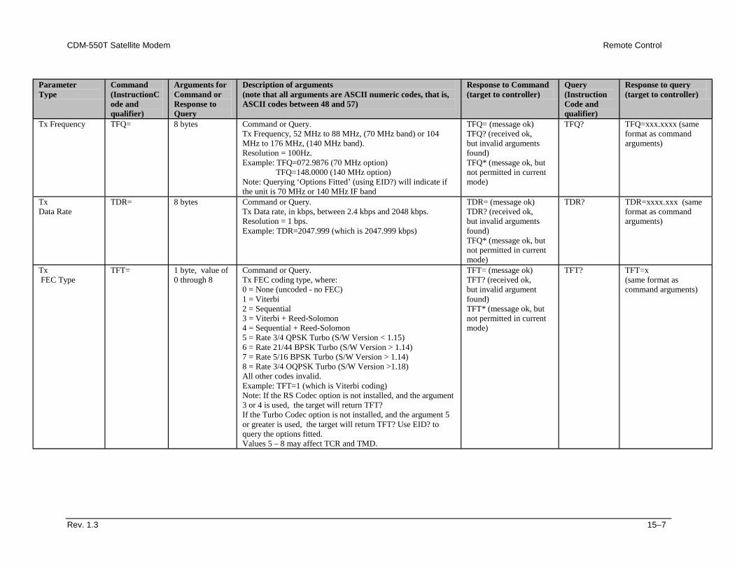
CDM-550T Satellite Modem Remote Control
Rev. 1.3 15–7
Parameter Type
Command (InstructionCode and qualifier)
Arguments for Command or Response to Query
Description of arguments (note that all arguments are ASCII numeric codes, that is, ASCII codes between 48 and 57)
Response to Command (target to controller)
Query (Instruction Code and qualifier)
Response to query (target to controller)
Tx Frequency TFQ= 8 bytes Command or Query. Tx Frequency, 52 MHz to 88 MHz, (70 MHz band) or 104 MHz to 176 MHz, (140 MHz band). Resolution = 100Hz. Example: TFQ=072.9876 (70 MHz option) TFQ=148.0000 (140 MHz option) Note: Querying ‘Options Fitted’ (using EID?) will indicate if the unit is 70 MHz or 140 MHz IF band
TFQ= (message ok) TFQ? (received ok, but invalid arguments found) TFQ* (message ok, but not permitted in current mode)
TFQ? TFQ=xxx.xxxx (same format as command arguments)
Tx Data Rate
TDR= 8 bytes Command or Query. Tx Data rate, in kbps, between 2.4 kbps and 2048 kbps. Resolution = 1 bps. Example: TDR=2047.999 (which is 2047.999 kbps)
TDR= (message ok) TDR? (received ok, but invalid arguments found) TFQ* (message ok, but not permitted in current mode)
TDR? TDR=xxxx.xxx (same format as command arguments)
Tx FEC Type
TFT= 1 byte, value of 0 through 8
Command or Query. Tx FEC coding type, where: 0 = None (uncoded - no FEC) 1 = Viterbi 2 = Sequential 3 = Viterbi + Reed-Solomon 4 = Sequential + Reed-Solomon 5 = Rate 3/4 QPSK Turbo (S/W Version < 1.15) 6 = Rate 21/44 BPSK Turbo (S/W Version > 1.14) 7 = Rate 5/16 BPSK Turbo (S/W Version > 1.14) 8 = Rate 3/4 OQPSK Turbo (S/W Version >1.18) All other codes invalid. Example: TFT=1 (which is Viterbi coding) Note: If the RS Codec option is not installed, and the argument 3 or 4 is used, the target will return TFT? If the Turbo Codec option is not installed, and the argument 5 or greater is used, the target will return TFT? Use EID? to query the options fitted. Values 5 – 8 may affect TCR and TMD.
TFT= (message ok) TFT? (received ok, but invalid argument found) TFT* (message ok, but not permitted in current mode)
TFT? TFT=x (same format as command arguments)
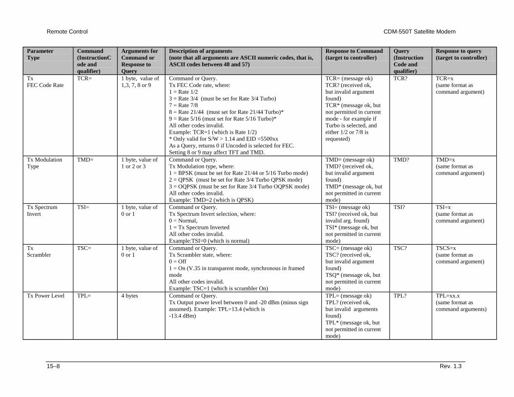
Remote Control CDM-550T Satellite Modem
15–8 Rev. 1.3
Parameter Type
Command (InstructionCode and qualifier)
Arguments for Command or Response to Query
Description of arguments (note that all arguments are ASCII numeric codes, that is, ASCII codes between 48 and 57)
Response to Command (target to controller)
Query (Instruction Code and qualifier)
Response to query (target to controller)
Tx FEC Code Rate
TCR= 1 byte, value of 1,3, 7, 8 or 9
Command or Query. Tx FEC Code rate, where: 1 = Rate 1/2 3 = Rate 3/4 (must be set for Rate 3/4 Turbo) 7 = Rate 7/8 8 = Rate 21/44 (must set for Rate 21/44 Turbo)* 9 = Rate 5/16 (must set for Rate 5/16 Turbo)* All other codes invalid. Example: TCR=1 (which is Rate 1/2) * Only valid for S/W > 1.14 and EID =5500xx As a Query, returns 0 if Uncoded is selected for FEC. Setting 8 or 9 may affect TFT and TMD.
TCR= (message ok) TCR? (received ok, but invalid argument found) TCR* (message ok, but not permitted in current mode - for example if Turbo is selected, and either 1/2 or 7/8 is requested)
TCR? TCR=x (same format as command argument)
Tx Modulation Type
TMD= 1 byte, value of 1 or 2 or 3
Command or Query. Tx Modulation type, where: 1 = BPSK (must be set for Rate 21/44 or 5/16 Turbo mode) 2 = QPSK (must be set for Rate 3/4 Turbo QPSK mode) 3 = OQPSK (must be set for Rate 3/4 Turbo OQPSK mode) All other codes invalid. Example: TMD=2 (which is QPSK)
TMD= (message ok) TMD? (received ok, but invalid argument found) TMD* (message ok, but not permitted in current mode)
TMD? TMD=x (same format as command argument)
Tx Spectrum Invert
TSI= 1 byte, value of 0 or 1
Command or Query. Tx Spectrum Invert selection, where: 0 = Normal, 1 = Tx Spectrum Inverted All other codes invalid. Example:TSI=0 (which is normal)
TSI= (message ok) TSI? (received ok, but invalid arg. found) TSI* (message ok, but not permitted in current mode)
TSI? TSI=x (same format as command argument)
Tx Scrambler
TSC= 1 byte, value of 0 or 1
Command or Query. Tx Scrambler state, where: 0 = Off 1 = On (V.35 in transparent mode, synchronous in framed mode All other codes invalid. Example: TSC=1 (which is scrambler On)
TSC= (message ok) TSC? (received ok, but invalid argument found) TSQ* (message ok, but not permitted in current mode)
TSC? TSCS=x (same format as command argument)
Tx Power Level TPL= 4 bytes Command or Query. Tx Output power level between 0 and -20 dBm (minus sign assumed). Example: TPL=13.4 (which is -13.4 dBm)
TPL= (message ok) TPL? (received ok, but invalid arguments found) TPL* (message ok, but not permitted in current mode)
TPL?
TPL=xx.x (same format as command arguments)
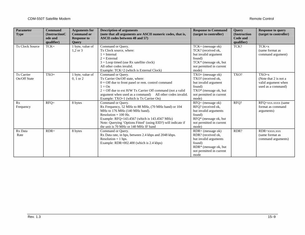
CDM-550T Satellite Modem Remote Control
Rev. 1.3 15–9
Parameter Type
Command (InstructionCode and qualifier)
Arguments for Command or Response to Query
Description of arguments (note that all arguments are ASCII numeric codes, that is, ASCII codes between 48 and 57)
Response to Command (target to controller)
Query (Instruction Code and qualifier)
Response to query (target to controller)
Tx Clock Source TCK=
1 byte, value of 1,2 or 3
Command or Query. Tx Clock source, where: 1 = Internal 2 = External 3 = Loop timed (use Rx satellite clock) All other codes invalid. Example: TCK=2 (which is External Clock)
TCK= (message ok) TCK? (received ok, but invalid argument found) TCK* (message ok, but not permitted in current mode)
TCK?
TCK=x (same format as command argument)
Tx Carrier On/Off State
TXO=
1 byte, value of 0, 1 or 2
Command or Query. Tx Carrier On/Off state, where: 0 = Off due to front panel or rem. control command 1 = On 2 = Off due to ext H/W Tx Carrier Off command (not a valid argument when used as a command) All other codes invalid. Example: TXO=1 (which is Tx Carrier On)
TXO= (message ok) TXO? (received ok, but invalid argument found) TXO* (message ok, but not permitted in current mode)
TXO? TXO=x (Note that 2 is not a valid argument when used as a command)
Rx Frequency
RFQ=
8 bytes
Command or Query. Rx Frequency, 52 MHz to 88 MHz, (70 MHz band) or 104 MHz to 176 MHz (140 MHz band). Resolution = 100 Hz. Example: RFQ=143.4567 (which is 143.4567 MHz) Note: Querying ‘Options Fitted’ (using EID?) will indicate if the unit is 70 MHz or 140 MHz IF band
RFQ= (message ok) RFQ? (received ok, but invalid arguments found) RFQ* (message ok, but not permitted in current mode)
RFQ? RFQ=xxx.xxxx (same format as command arguments)
Rx Data Rate
RDR= 8 bytes Command or Query. Rx Data rate, in bps, between 2.4 kbps and 2048 kbps. Resolution = 1 bps. Example: RDR=002.400 (which is 2.4 kbps)
RDR= (message ok) RDR? (received ok, but invalid arguments found) RDR* (message ok, but not permitted in current mode
RDR? RDR=xxxx.xxx (same format as command arguments)
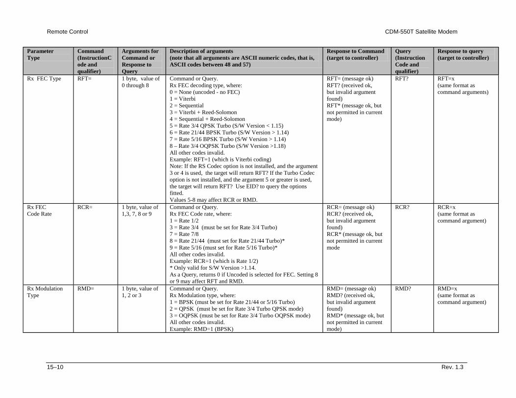
Remote Control CDM-550T Satellite Modem
15–10 Rev. 1.3
Parameter Type
Command (InstructionCode and qualifier)
Arguments for Command or Response to Query
Description of arguments (note that all arguments are ASCII numeric codes, that is, ASCII codes between 48 and 57)
Response to Command (target to controller)
Query (Instruction Code and qualifier)
Response to query (target to controller)
Rx FEC Type RFT= 1 byte, value of 0 through 8
Command or Query. Rx FEC decoding type, where: 0 = None (uncoded - no FEC) 1 = Viterbi 2 = Sequential 3 = Viterbi + Reed-Solomon 4 = Sequential + Reed-Solomon 5 = Rate 3/4 QPSK Turbo (S/W Version < 1.15) 6 = Rate 21/44 BPSK Turbo (S/W Version > 1.14) 7 = Rate 5/16 BPSK Turbo (S/W Version > 1.14) 8 – Rate 3/4 OQPSK Turbo (S/W Version >1.18) All other codes invalid. Example: RFT=1 (which is Viterbi coding) Note: If the RS Codec option is not installed, and the argument 3 or 4 is used, the target will return RFT? If the Turbo Codec option is not installed, and the argument 5 or greater is used, the target will return RFT? Use EID? to query the options fitted. Values 5-8 may affect RCR or RMD.
RFT= (message ok) RFT? (received ok, but invalid argument found) RFT* (message ok, but not permitted in current mode)
RFT? RFT=x (same format as command arguments)
Rx FEC Code Rate
RCR= 1 byte, value of 1,3, 7, 8 or 9
Command or Query. Rx FEC Code rate, where: 1 = Rate 1/2 3 = Rate 3/4 (must be set for Rate 3/4 Turbo) 7 = Rate 7/8 8 = Rate 21/44 (must set for Rate 21/44 Turbo)* 9 = Rate 5/16 (must set for Rate 5/16 Turbo)* All other codes invalid. Example: RCR=1 (which is Rate 1/2) * Only valid for S/W Version >1.14. As a Query, returns 0 if Uncoded is selected for FEC. Setting 8 or 9 may affect RFT and RMD.
RCR= (message ok) RCR? (received ok, but invalid argument found) RCR* (message ok, but not permitted in current mode
RCR? RCR=x (same format as command argument)
Rx Modulation Type
RMD=
1 byte, value of 1, 2 or 3
Command or Query. Rx Modulation type, where: 1 = BPSK (must be set for Rate 21/44 or 5/16 Turbo) 2 = QPSK (must be set for Rate 3/4 Turbo QPSK mode) 3 = OQPSK (must be set for Rate 3/4 Turbo OQPSK mode) All other codes invalid. Example: RMD=1 (BPSK)
RMD= (message ok) RMD? (received ok, but invalid argument found) RMD* (message ok, but not permitted in current mode)
RMD?
RMD=x (same format as command argument)
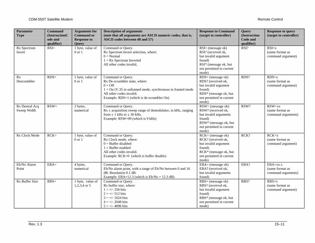
CDM-550T Satellite Modem Remote Control
Rev. 1.3 15–11
Parameter Type
Command (InstructionCode and qualifier)
Arguments for Command or Response to Query
Description of arguments (note that all arguments are ASCII numeric codes, that is, ASCII codes between 48 and 57)
Response to Command (target to controller)
Query (Instruction Code and qualifier)
Response to query (target to controller)
Rx Spectrum Invert
RSI= 1 byte, value of 0 or 1
Command or Query. Rx Spectrum Invert selection, where: 0 = Normal 1 = Rx Spectrum Inverted All other codes invalid.
RSI= (message ok) RSI? (received ok, but invalid argument found) RSI* (message ok, but not permitted in current mode)
RSI?
RSI=x (same format as command argument)
Rx Descrambler
RDS= 1 byte, value of 0 or 1
Command or Query. Rx De-scrambler state, where: 0 = Off 1 = On (V.35 in unframed mode, synchronous in framed mode All other codes invalid. Example: RDS=1 (which is de-scrambler On)
RDS= (message ok) RDS? (received ok, but invalid argument found) RDS* (message ok, but not permitted in current mode)
RDS? RDS=x (same format as command argument)
Rx Demod Acq Sweep Width
RSW= 2 bytes, numerical
Command or Query. Rx ± acquisition sweep range of demodulator, in kHz, ranging from ± 1 kHz to ± 30 kHz. Example: RSW=09 (which is 9 kHz)
RSW= (message ok) RSW? (received ok, but invalid arguments found) RSW* (message ok, but not permitted in current mode)
RSW? RSW=xx (same format as command arguments)
Rx Clock Mode RCK= 1 byte, value of 0 or 1
Command or Query. Rx Clock mode, where: 0 = Buffer disabled 1 = Buffer enabled All other codes invalid. Example: RCK=0 (which is buffer disable)
RCK= (message ok) RCK? (received ok, but invalid argument found) RCK* (message ok, but not permitted in current mode)
RCK? RCK=x (same format as command argument)
Eb/No Alarm Point
EBA= 4 bytes, numerical
Command or Query. Eb/No alarm point, with a range of Eb/No between 0 and 16 dB. Resolution 0.1 dB. Example: EBA=12.3 (which is Eb/No = 12.3 dB)
EBA= (message ok) EBA? (received ok, but invalid arguments found)
EBA? EBA=xx.x (same format as command arguments)
Rx Buffer Size RBS= 1 byte, value of 1,2,3,4 or 5
Command or Query. Rx buffer size, where: 1 = +/- 256 bits 2 = +/- 512 bits 3 = +/- 1024 bits 4 = +/- 2048 bits 5 = +/- 4096 bits
RBS= (message ok) RBS? (received ok, but invalid argument found) RBS* (message ok, but not permitted in current mode)
RBS? RBS=x (same format as command argument)
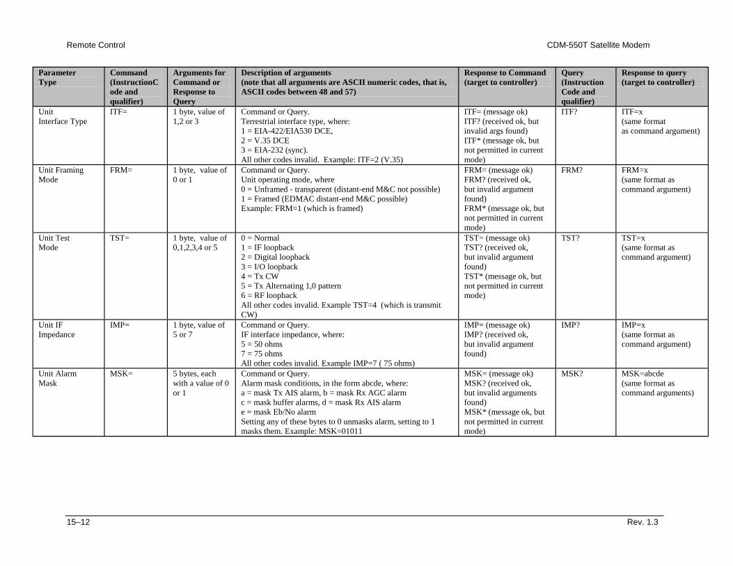
Remote Control CDM-550T Satellite Modem
15–12 Rev. 1.3
Parameter Type
Command (InstructionCode and qualifier)
Arguments for Command or Response to Query
Description of arguments (note that all arguments are ASCII numeric codes, that is, ASCII codes between 48 and 57)
Response to Command (target to controller)
Query (Instruction Code and qualifier)
Response to query (target to controller)
Unit Interface Type
ITF= 1 byte, value of 1,2 or 3
Command or Query. Terrestrial interface type, where: 1 = EIA-422/EIA530 DCE, 2 = V.35 DCE 3 = EIA-232 (sync). All other codes invalid. Example: ITF=2 (V.35)
ITF= (message ok) ITF? (received ok, but invalid args found) ITF* (message ok, but not permitted in current mode)
ITF? ITF=x (same format as command argument)
Unit Framing Mode
FRM= 1 byte, value of 0 or 1
Command or Query. Unit operating mode, where 0 = Unframed - transparent (distant-end M&C not possible) 1 = Framed (EDMAC distant-end M&C possible) Example: FRM=1 (which is framed)
FRM= (message ok) FRM? (received ok, but invalid argument found) FRM* (message ok, but not permitted in current mode)
FRM? FRM=x (same format as command argument)
Unit Test Mode
TST= 1 byte, value of 0,1,2,3,4 or 5
0 = Normal 1 = IF loopback 2 = Digital loopback 3 = I/O loopback 4 = Tx CW 5 = Tx Alternating 1,0 pattern 6 = RF loopback All other codes invalid. Example TST=4 (which is transmit CW)
TST= (message ok) TST? (received ok, but invalid argument found) TST* (message ok, but not permitted in current mode)
TST? TST=x (same format as command argument)
Unit IF Impedance
IMP= 1 byte, value of 5 or 7
Command or Query. IF interface impedance, where: 5 = 50 ohms 7 = 75 ohms All other codes invalid. Example IMP=7 ( 75 ohms)
IMP= (message ok) IMP? (received ok, but invalid argument found)
IMP? IMP=x (same format as command argument)
Unit Alarm Mask
MSK= 5 bytes, each with a value of 0 or 1
Command or Query. Alarm mask conditions, in the form abcde, where: a = mask Tx AIS alarm, b = mask Rx AGC alarm c = mask buffer alarms, d = mask Rx AIS alarm e = mask Eb/No alarm Setting any of these bytes to 0 unmasks alarm, setting to 1 masks them. Example: MSK=01011
MSK= (message ok) MSK? (received ok, but invalid arguments found) MSK* (message ok, but not permitted in current mode)
MSK? MSK=abcde (same format as command arguments)
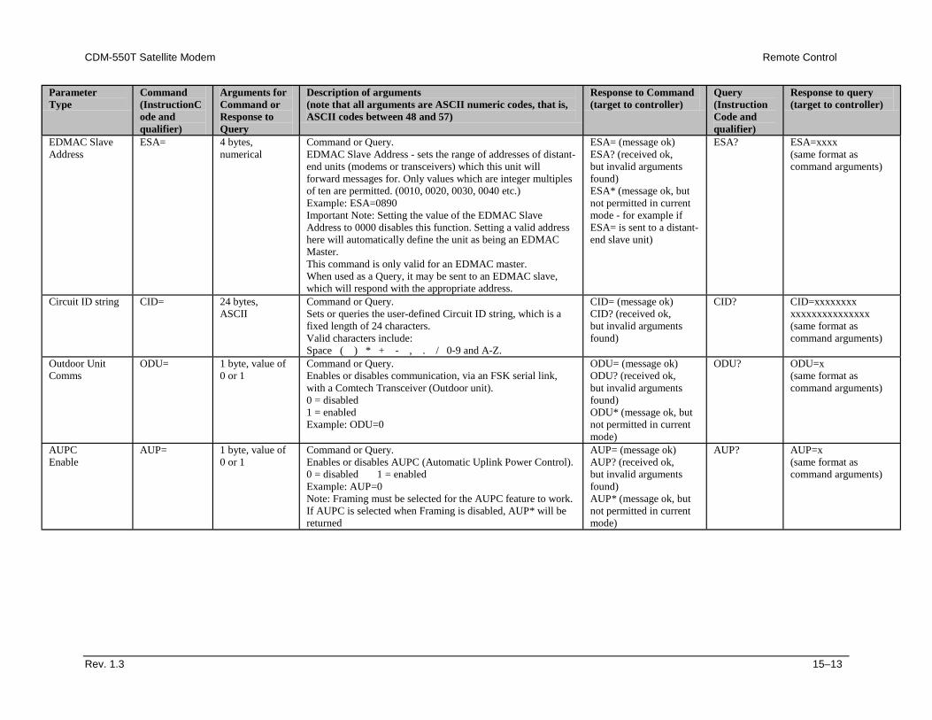
CDM-550T Satellite Modem Remote Control
Rev. 1.3 15–13
Parameter Type
Command (InstructionCode and qualifier)
Arguments for Command or Response to Query
Description of arguments (note that all arguments are ASCII numeric codes, that is, ASCII codes between 48 and 57)
Response to Command (target to controller)
Query (Instruction Code and qualifier)
Response to query (target to controller)
EDMAC Slave Address
ESA= 4 bytes, numerical
Command or Query. EDMAC Slave Address - sets the range of addresses of distant-end units (modems or transceivers) which this unit will forward messages for. Only values which are integer multiples of ten are permitted. (0010, 0020, 0030, 0040 etc.) Example: ESA=0890 Important Note: Setting the value of the EDMAC Slave Address to 0000 disables this function. Setting a valid address here will automatically define the unit as being an EDMAC Master. This command is only valid for an EDMAC master. When used as a Query, it may be sent to an EDMAC slave, which will respond with the appropriate address.
ESA= (message ok) ESA? (received ok, but invalid arguments found) ESA* (message ok, but not permitted in current mode - for example if ESA= is sent to a distant-end slave unit)
ESA? ESA=xxxx (same format as command arguments)
Circuit ID string CID= 24 bytes, ASCII
Command or Query. Sets or queries the user-defined Circuit ID string, which is a fixed length of 24 characters. Valid characters include: Space ( ) * + - , . / 0-9 and A-Z.
CID= (message ok) CID? (received ok, but invalid arguments found)
CID? CID=xxxxxxxx xxxxxxxxxxxxxxx (same format as command arguments)
Outdoor Unit Comms
ODU= 1 byte, value of 0 or 1
Command or Query. Enables or disables communication, via an FSK serial link, with a Comtech Transceiver (Outdoor unit). 0 = disabled 1 = enabled Example: ODU=0
ODU= (message ok) ODU? (received ok, but invalid arguments found) ODU* (message ok, but not permitted in current mode)
ODU? ODU=x (same format as command arguments)
AUPC Enable
AUP= 1 byte, value of 0 or 1
Command or Query. Enables or disables AUPC (Automatic Uplink Power Control). 0 = disabled 1 = enabled Example: AUP=0 Note: Framing must be selected for the AUPC feature to work. If AUPC is selected when Framing is disabled, AUP* will be returned
AUP= (message ok) AUP? (received ok, but invalid arguments found) AUP* (message ok, but not permitted in current mode)
AUP? AUP=x (same format as command arguments)
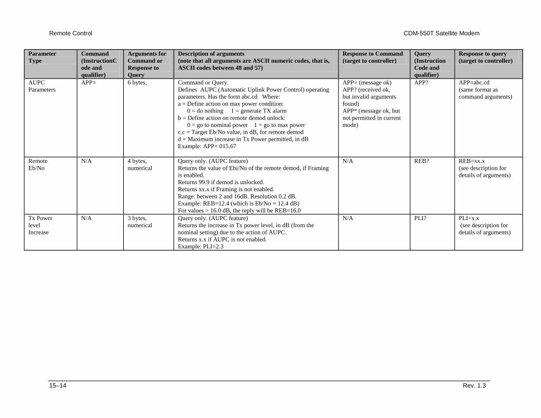
Remote Control CDM-550T Satellite Modem
15–14 Rev. 1.3
Parameter Type
Command (InstructionCode and qualifier)
Arguments for Command or Response to Query
Description of arguments (note that all arguments are ASCII numeric codes, that is, ASCII codes between 48 and 57)
Response to Command (target to controller)
Query (Instruction Code and qualifier)
Response to query (target to controller)
AUPC Parameters
APP= 6 bytes, Command or Query. Defines AUPC (Automatic Uplink Power Control) operating parameters. Has the form abc.cd Where: a = Define action on max power condition: 0 = do nothing 1 = generate TX alarm b = Define action on remote demod unlock: 0 = go to nominal power 1 = go to max power c.c = Target Eb/No value, in dB, for remote demod d = Maximum increase in Tx Power permitted, in dB Example: APP= 015.67
APP= (message ok) APP? (received ok, but invalid arguments found) APP* (message ok, but not permitted in current mode)
APP? APP=abc.cd (same format as command arguments)
Remote Eb/No
N/A 4 bytes, numerical
Query only. (AUPC feature) Returns the value of Ebi/No of the remote demod, if Framing is enabled. Returns 99.9 if demod is unlocked. Returns xx.x if Framing is not enabled. Range: between 2 and 16dB. Resolution 0.2 dB. Example: REB=12.4 (which is Eb/No = 12.4 dB) For values > 16.0 dB, the reply will be REB=16.0
N/A REB? REB=xx.x (see description for details of arguments)
Tx Power level Increase
N/A 3 bytes, numerical
Query only. (AUPC feature) Returns the increase in Tx power level, in dB (from the nominal setting) due to the action of AUPC. Returns x.x if AUPC is not enabled. Example: PLI=2.3
N/A PLI? PLI=x.x (see description for details of arguments)
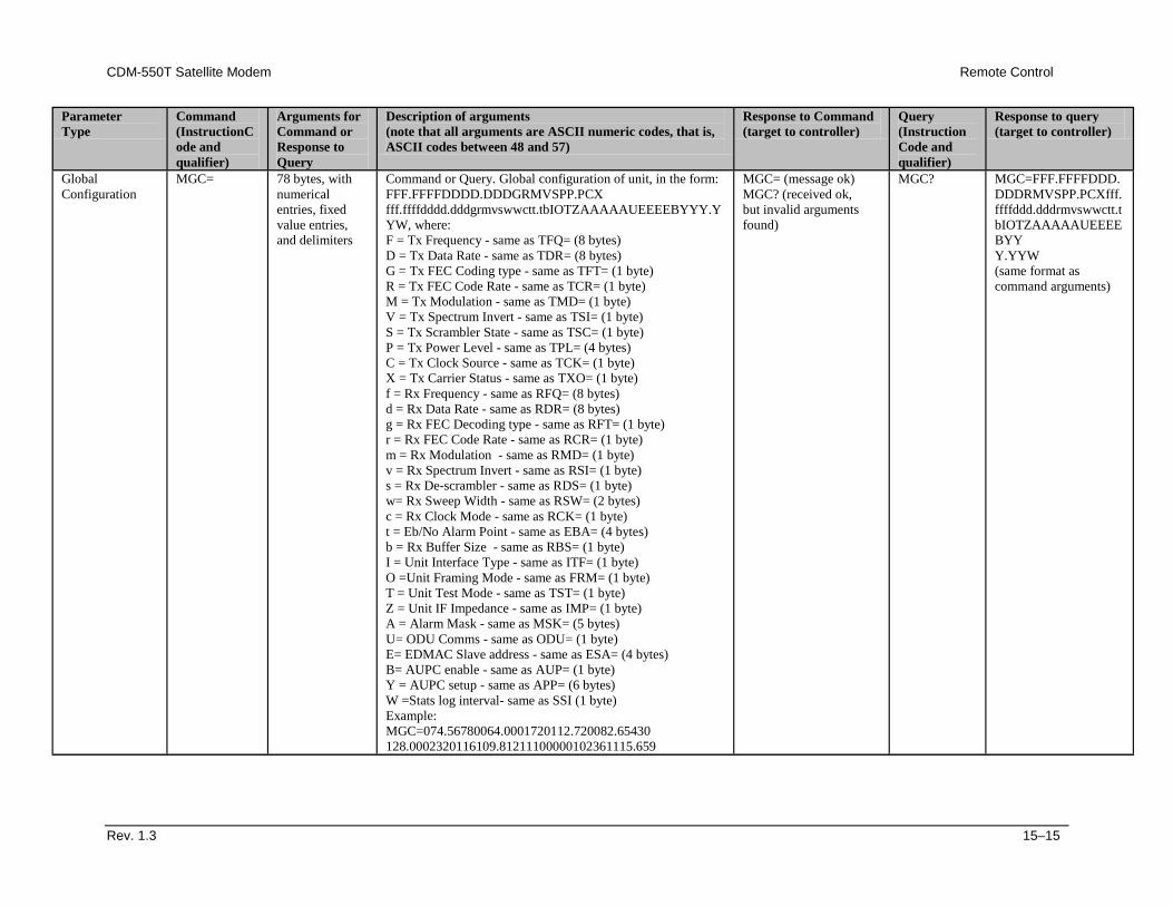
CDM-550T Satellite Modem Remote Control
Rev. 1.3 15–15
Parameter Type
Command (InstructionCode and qualifier)
Arguments for Command or Response to Query
Description of arguments (note that all arguments are ASCII numeric codes, that is, ASCII codes between 48 and 57)
Response to Command (target to controller)
Query (Instruction Code and qualifier)
Response to query (target to controller)
Global Configuration
MGC= 78 bytes, with numerical entries, fixed value entries, and delimiters
Command or Query. Global configuration of unit, in the form: FFF.FFFFDDDD.DDDGRMVSPP.PCX fff.ffffdddd.dddgrmvswwctt.tbIOTZAAAAAUEEEEBYYY.YYW, where: F = Tx Frequency - same as TFQ= (8 bytes) D = Tx Data Rate - same as TDR= (8 bytes) G = Tx FEC Coding type - same as TFT= (1 byte) R = Tx FEC Code Rate - same as TCR= (1 byte) M = Tx Modulation - same as TMD= (1 byte) V = Tx Spectrum Invert - same as TSI= (1 byte) S = Tx Scrambler State - same as TSC= (1 byte) P = Tx Power Level - same as TPL= (4 bytes) C = Tx Clock Source - same as TCK= (1 byte) X = Tx Carrier Status - same as TXO= (1 byte) f = Rx Frequency - same as RFQ= (8 bytes) d = Rx Data Rate - same as RDR= (8 bytes) g = Rx FEC Decoding type - same as RFT= (1 byte) r = Rx FEC Code Rate - same as RCR= (1 byte) m = Rx Modulation - same as RMD= (1 byte) v = Rx Spectrum Invert - same as RSI= (1 byte) s = Rx De-scrambler - same as RDS= (1 byte) w= Rx Sweep Width - same as RSW= (2 bytes) c = Rx Clock Mode - same as RCK= (1 byte) t = Eb/No Alarm Point - same as EBA= (4 bytes) b = Rx Buffer Size - same as RBS= (1 byte) I = Unit Interface Type - same as ITF= (1 byte) O =Unit Framing Mode - same as FRM= (1 byte) T = Unit Test Mode - same as TST= (1 byte) Z = Unit IF Impedance - same as IMP= (1 byte) A = Alarm Mask - same as MSK= (5 bytes) U= ODU Comms - same as ODU= (1 byte) E= EDMAC Slave address - same as ESA= (4 bytes) B= AUPC enable - same as AUP= (1 byte) Y = AUPC setup - same as APP= (6 bytes) W =Stats log interval- same as SSI (1 byte) Example: MGC=074.56780064.0001720112.720082.65430 128.0002320116109.81211100000102361115.659
MGC= (message ok) MGC? (received ok, but invalid arguments found)
MGC? MGC=FFF.FFFFDDD.DDDRMVSPP.PCXfff.ffffddd.dddrmvswwctt.tbIOTZAAAAAUEEEEBYY Y.YYW (same format as command arguments)
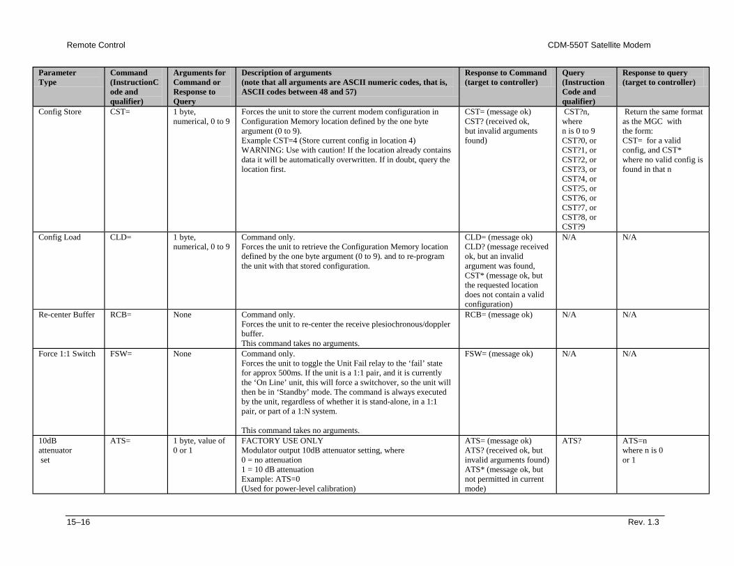
Remote Control CDM-550T Satellite Modem
15–16 Rev. 1.3
Parameter Type
Command (InstructionCode and qualifier)
Arguments for Command or Response to Query
Description of arguments (note that all arguments are ASCII numeric codes, that is, ASCII codes between 48 and 57)
Response to Command (target to controller)
Query (Instruction Code and qualifier)
Response to query (target to controller)
Config Store CST= 1 byte, numerical, 0 to 9
Forces the unit to store the current modem configuration in Configuration Memory location defined by the one byte argument (0 to 9). Example CST=4 (Store current config in location 4) WARNING: Use with caution! If the location already contains data it will be automatically overwritten. If in doubt, query the location first.
CST= (message ok) CST? (received ok, but invalid arguments found)
CST?n, where n is 0 to 9 CST?0, or CST?1, or CST?2, or CST?3, or CST?4, or CST?5, or CST?6, or CST?7, or CST?8, or CST?9
Return the same format as the MGC with the form: CST= for a valid config, and CST* where no valid config is found in that n
Config Load CLD= 1 byte, numerical, 0 to 9
Command only. Forces the unit to retrieve the Configuration Memory location defined by the one byte argument (0 to 9). and to re-program the unit with that stored configuration.
CLD= (message ok) CLD? (message received ok, but an invalid argument was found, CST* (message ok, but the requested location does not contain a valid configuration)
N/A N/A
Re-center Buffer RCB= None Command only. Forces the unit to re-center the receive plesiochronous/doppler buffer. This command takes no arguments.
RCB= (message ok) N/A N/A
Force 1:1 Switch FSW= None Command only. Forces the unit to toggle the Unit Fail relay to the ‘fail’ state for approx 500ms. If the unit is a 1:1 pair, and it is currently the ‘On Line’ unit, this will force a switchover, so the unit will then be in ‘Standby’ mode. The command is always executed by the unit, regardless of whether it is stand-alone, in a 1:1 pair, or part of a 1:N system. This command takes no arguments.
FSW= (message ok) N/A N/A
10dB attenuator set
ATS= 1 byte, value of 0 or 1
FACTORY USE ONLY Modulator output 10dB attenuator setting, where 0 = no attenuation 1 = 10 dB attenuation Example: ATS=0 (Used for power-level calibration)
ATS= (message ok) ATS? (received ok, but invalid arguments found) ATS* (message ok, but not permitted in current mode)
ATS? ATS=n where n is 0 or 1
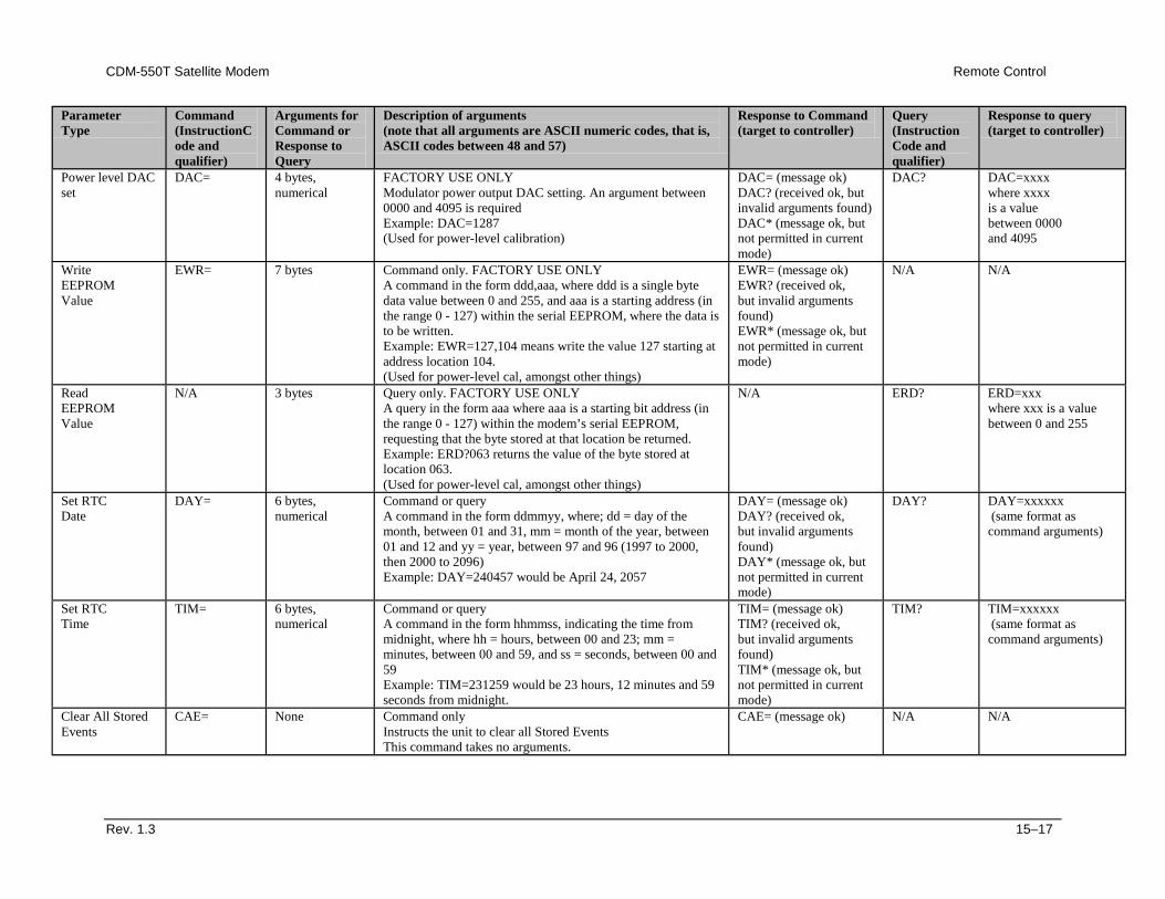
CDM-550T Satellite Modem Remote Control
Rev. 1.3 15–17
Parameter Type
Command (InstructionCode and qualifier)
Arguments for Command or Response to Query
Description of arguments (note that all arguments are ASCII numeric codes, that is, ASCII codes between 48 and 57)
Response to Command (target to controller)
Query (Instruction Code and qualifier)
Response to query (target to controller)
Power level DAC set
DAC= 4 bytes, numerical
FACTORY USE ONLY Modulator power output DAC setting. An argument between 0000 and 4095 is required Example: DAC=1287 (Used for power-level calibration)
DAC= (message ok) DAC? (received ok, but invalid arguments found) DAC* (message ok, but not permitted in current mode)
DAC? DAC=xxxx where xxxx is a value between 0000 and 4095
Write EEPROM Value
EWR= 7 bytes Command only. FACTORY USE ONLY A command in the form ddd,aaa, where ddd is a single byte data value between 0 and 255, and aaa is a starting address (in the range 0 - 127) within the serial EEPROM, where the data is to be written. Example: EWR=127,104 means write the value 127 starting at address location 104. (Used for power-level cal, amongst other things)
EWR= (message ok) EWR? (received ok, but invalid arguments found) EWR* (message ok, but not permitted in current mode)
N/A N/A
Read EEPROM Value
N/A 3 bytes Query only. FACTORY USE ONLY A query in the form aaa where aaa is a starting bit address (in the range 0 - 127) within the modem’s serial EEPROM, requesting that the byte stored at that location be returned. Example: ERD?063 returns the value of the byte stored at location 063. (Used for power-level cal, amongst other things)
N/A ERD? ERD=xxx where xxx is a value between 0 and 255
Set RTC Date
DAY= 6 bytes, numerical
Command or query A command in the form ddmmyy, where; dd = day of the month, between 01 and 31, mm = month of the year, between 01 and 12 and yy = year, between 97 and 96 (1997 to 2000, then 2000 to 2096) Example: DAY=240457 would be April 24, 2057
DAY= (message ok) DAY? (received ok, but invalid arguments found) DAY* (message ok, but not permitted in current mode)
DAY? DAY=xxxxxx (same format as command arguments)
Set RTC Time
TIM= 6 bytes, numerical
Command or query A command in the form hhmmss, indicating the time from midnight, where hh = hours, between 00 and 23; mm = minutes, between 00 and 59, and ss = seconds, between 00 and 59 Example: TIM=231259 would be 23 hours, 12 minutes and 59 seconds from midnight.
TIM= (message ok) TIM? (received ok, but invalid arguments found) TIM* (message ok, but not permitted in current mode)
TIM? TIM=xxxxxx (same format as command arguments)
Clear All Stored Events
CAE= None Command only Instructs the unit to clear all Stored Events This command takes no arguments.
CAE= (message ok) N/A N/A
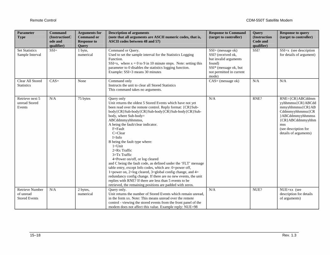
Remote Control CDM-550T Satellite Modem
15–18 Rev. 1.3
Parameter Type
Command (InstructionCode and qualifier)
Arguments for Command or Response to Query
Description of arguments (note that all arguments are ASCII numeric codes, that is, ASCII codes between 48 and 57)
Response to Command (target to controller)
Query (Instruction Code and qualifier)
Response to query (target to controller)
Set Statistics Sample Interval
SSI= 1 byte, numerical
Command or Query. Used to set the sample interval for the Statistics Logging Function. SSI=x, where x = 0 to 9 in 10 minute steps. Note: setting this parameter to 0 disables the statistics logging function. Example: SSI=3 means 30 minutes
SSI= (message ok) SSI? (received ok, but invalid arguments found) SSI* (message ok, but not permitted in current mode)
SSI? SSI=x (see description for details of argument)
Clear All Stored Statistics
CAS= None Command only Instructs the unit to clear all Stored Statistics This command takes no arguments.
CAS= (message ok) N/A N/A
Retrieve next 5 unread Stored Events
N/A 75 bytes Query only Unit returns the oldest 5 Stored Events which have not yet been read over the remote control. Reply format: {CR}Sub-body{CR}Sub-body{CR}Sub-body{CR}Sub-body{CR}Sub-body, where Sub-body= ABCddmmyyhhmmss, A being the fault/clear indicator. F=Fault C=Clear I=Info B being the fault type where: 1=Unit 2=Rx Traffic 3=Tx Traffic 4=Power on/off, or log cleared and C being the fault code, as defined under the ‘FLT’ message table entry, except Info codes, which are: 0=power off, 1=power on, 2=log cleared, 3=global config change, and 4= redundancy config change. If there are no new events, the unit replies with RNE? If there are less than 5 events to be retrieved, the remaining positions are padded with zeros.
N/A RNE? RNE={CR}ABCddmmyyhhmmss{CR}ABCddmmyyhhmmss{CR}ABCddmmyyhhmmss{CR}ABCddmmyyhhmmss{CR}ABCddmmyyhhmmss (see description for details of arguments)
Retrieve Number of unread Stored Events
N/A 2 bytes, numerical
Query only. Unit returns the number of Stored Events which remain unread, in the form xx. Note: This means unread over the remote control - viewing the stored events from the front panel of the modem does not affect this value. Example reply: NUE=98
N/A NUE? NUE=xx (see description for details of arguments)
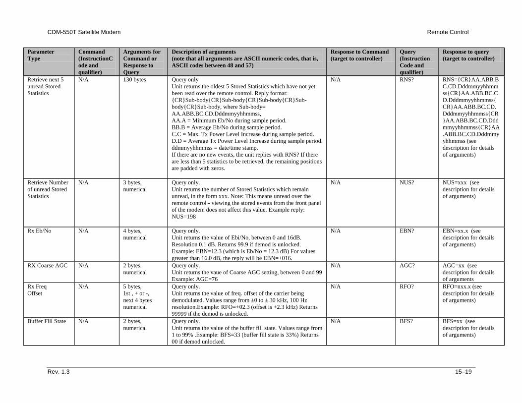
CDM-550T Satellite Modem Remote Control
Rev. 1.3 15–19
Parameter Type
Command (InstructionCode and qualifier)
Arguments for Command or Response to Query
Description of arguments (note that all arguments are ASCII numeric codes, that is, ASCII codes between 48 and 57)
Response to Command (target to controller)
Query (Instruction Code and qualifier)
Response to query (target to controller)
Retrieve next 5 unread Stored Statistics
N/A 130 bytes Query only Unit returns the oldest 5 Stored Statistics which have not yet been read over the remote control. Reply format: {CR}Sub-body{CR}Sub-body{CR}Sub-body{CR}Sub-body{CR}Sub-body, where Sub-body= AA.ABB.BC.CD.Dddmmyyhhmmss, AA.A = Minimum Eb/No during sample period. BB.B = Average Eb/No during sample period. C.C = Max. Tx Power Level Increase during sample period. D.D = Average Tx Power Level Increase during sample period. ddmmyyhhmmss = date/time stamp. If there are no new events, the unit replies with RNS? If there are less than 5 statistics to be retrieved, the remaining positions are padded with zeros.
N/A RNS? RNS={CR}AA.ABB.BC.CD.Dddmmyyhhmmss{CR}AA.ABB.BC.CD.Dddmmyyhhmmss{CR}AA.ABB.BC.CD.Dddmmyyhhmmss{CR}AA.ABB.BC.CD.Dddmmyyhhmmss{CR}AA.ABB.BC.CD.Dddmmyyhhmmss (see description for details of arguments)
Retrieve Number of unread Stored Statistics
N/A 3 bytes, numerical
Query only. Unit returns the number of Stored Statistics which remain unread, in the form xxx. Note: This means unread over the remote control - viewing the stored events from the front panel of the modem does not affect this value. Example reply: NUS=198
N/A NUS? NUS=xxx (see description for details of arguments)
Rx Eb/No N/A 4 bytes, numerical
Query only. Unit returns the value of Ebi/No, between 0 and 16dB. Resolution 0.1 dB. Returns 99.9 if demod is unlocked. Example: EBN=12.3 (which is Eb/No = 12.3 dB) For values greater than 16.0 dB, the reply will be EBN=+016.
N/A EBN? EBN=xx.x (see description for details of arguments)
RX Coarse AGC N/A 2 bytes, numerical
Query only. Unit returns the vaue of Coarse AGC setting, between 0 and 99 Example: AGC=76
N/A AGC? AGC=xx (see description for details of arguments
Rx Freq Offset
N/A 5 bytes, 1st , + or -, next 4 bytes numerical
Query only. Unit returns the value of freq. offset of the carrier being demodulated. Values range from ±0 to ± 30 kHz, 100 Hz resolution.Example: RFO=+02.3 (offset is +2.3 kHz) Returns 99999 if the demod is unlocked.
N/A RFO? RFO=nxx.x (see description for details of arguments)
Buffer Fill State N/A 2 bytes, numerical
Query only. Unit returns the value of the buffer fill state. Values range from 1 to 99% .Example: BFS=33 (buffer fill state is 33%) Returns 00 if demod unlocked.
N/A BFS? BFS=xx (see description for details of arguments)
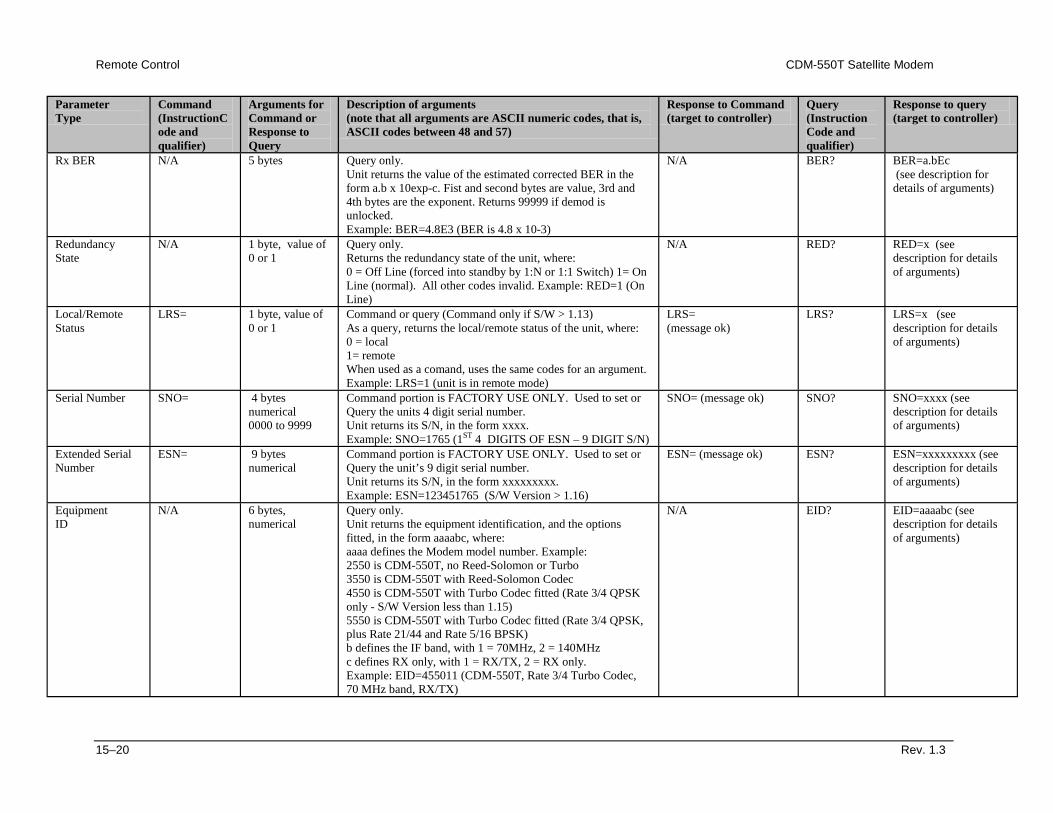
Remote Control CDM-550T Satellite Modem
15–20 Rev. 1.3
Parameter Type
Command (InstructionCode and qualifier)
Arguments for Command or Response to Query
Description of arguments (note that all arguments are ASCII numeric codes, that is, ASCII codes between 48 and 57)
Response to Command (target to controller)
Query (Instruction Code and qualifier)
Response to query (target to controller)
Rx BER N/A 5 bytes Query only. Unit returns the value of the estimated corrected BER in the form a.b x 10exp-c. Fist and second bytes are value, 3rd and 4th bytes are the exponent. Returns 99999 if demod is unlocked. Example: BER=4.8E3 (BER is 4.8 x 10⁻³)
N/A BER? BER=a.bEc (see description for details of arguments)
Redundancy State
N/A 1 byte, value of 0 or 1
Query only. Returns the redundancy state of the unit, where: 0 = Off Line (forced into standby by 1:N or 1:1 Switch) 1= On Line (normal). All other codes invalid. Example: RED=1 (On Line)
N/A RED? RED=x (see description for details of arguments)
Local/Remote Status
LRS= 1 byte, value of 0 or 1
Command or query (Command only if S/W > 1.13) As a query, returns the local/remote status of the unit, where: 0 = local 1= remote When used as a comand, uses the same codes for an argument. Example: LRS=1 (unit is in remote mode)
LRS= (message ok)
LRS? LRS=x (see description for details of arguments)
Serial Number SNO= 4 bytes numerical 0000 to 9999
Command portion is FACTORY USE ONLY. Used to set or Query the units 4 digit serial number. Unit returns its S/N, in the form xxxx. Example: SNO=1765 (1ST 4 DIGITS OF ESN – 9 DIGIT S/N)
SNO= (message ok) SNO? SNO=xxxx (see description for details of arguments)
Extended Serial Number
ESN= 9 bytes numerical
Command portion is FACTORY USE ONLY. Used to set or Query the unit’s 9 digit serial number. Unit returns its S/N, in the form xxxxxxxxx. Example: ESN=123451765 (S/W Version > 1.16)
ESN= (message ok) ESN? ESN=xxxxxxxxx (see description for details of arguments)
Equipment ID
N/A 6 bytes, numerical
Query only. Unit returns the equipment identification, and the options fitted, in the form aaaabc, where: aaaa defines the Modem model number. Example: 2550 is CDM-550T, no Reed-Solomon or Turbo 3550 is CDM-550T with Reed-Solomon Codec 4550 is CDM-550T with Turbo Codec fitted (Rate 3/4 QPSK only - S/W Version less than 1.15) 5550 is CDM-550T with Turbo Codec fitted (Rate 3/4 QPSK, plus Rate 21/44 and Rate 5/16 BPSK) b defines the IF band, with 1 = 70MHz, 2 = 140MHz c defines RX only, with 1 = RX/TX, 2 = RX only. Example: EID=455011 (CDM-550T, Rate 3/4 Turbo Codec, 70 MHz band, RX/TX)
N/A EID? EID=aaaabc (see description for details of arguments)
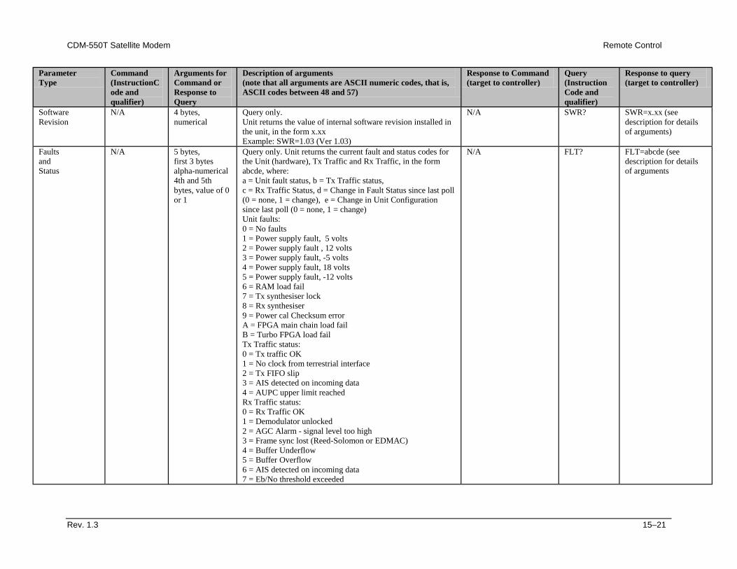
CDM-550T Satellite Modem Remote Control
Rev. 1.3 15–21
Parameter Type
Command (InstructionCode and qualifier)
Arguments for Command or Response to Query
Description of arguments (note that all arguments are ASCII numeric codes, that is, ASCII codes between 48 and 57)
Response to Command (target to controller)
Query (Instruction Code and qualifier)
Response to query (target to controller)
Software Revision
N/A 4 bytes, numerical
Query only. Unit returns the value of internal software revision installed in the unit, in the form x.xx Example: SWR=1.03 (Ver 1.03)
N/A SWR? SWR=x.xx (see description for details of arguments)
Faults and Status
N/A 5 bytes, first 3 bytes alpha-numerical 4th and 5th bytes, value of 0 or 1
Query only. Unit returns the current fault and status codes for the Unit (hardware), Tx Traffic and Rx Traffic, in the form abcde, where: a = Unit fault status, b = Tx Traffic status, c = Rx Traffic Status, d = Change in Fault Status since last poll (0 = none, 1 = change), e = Change in Unit Configuration since last poll (0 = none, 1 = change) Unit faults: 0 = No faults 1 = Power supply fault, 5 volts 2 = Power supply fault , 12 volts 3 = Power supply fault, -5 volts 4 = Power supply fault, 18 volts 5 = Power supply fault, -12 volts 6 = RAM load fail 7 = Tx synthesiser lock 8 = Rx synthesiser 9 = Power cal Checksum error A = FPGA main chain load fail B = Turbo FPGA load fail Tx Traffic status: 0 = Tx traffic OK 1 = No clock from terrestrial interface 2 = Tx FIFO slip 3 = AIS detected on incoming data 4 = AUPC upper limit reached Rx Traffic status: 0 = Rx Traffic OK 1 = Demodulator unlocked 2 = AGC Alarm - signal level too high 3 = Frame sync lost (Reed-Solomon or EDMAC) 4 = Buffer Underflow 5 = Buffer Overflow 6 = AIS detected on incoming data 7 = Eb/No threshold exceeded
N/A FLT? FLT=abcde (see description for details of arguments

Remote Control CDM-550T Satellite Modem
15–22 Rev. 1.3
This page has been intentionally left blank.
Rev. 1.3 A–1
AAppendix A. CABLE DRAWINGS
The EIA-530 standard pinout (provided on the CDM-550T) is becoming more popular in many applications. However, there are still many occasions when, especially for existing EIA-422/449 and V.35 users, a conversion must be made. For these situations, the following two cable drawings show EIA-530 to EIA-422/449 DCE conversion, and EIA-530 to V.35 DCE conversion. The third drawing shows a standard EIA-232 cable for use with the Remote Control Port of the Modem. This should also be used for performing Flash Upgrading via an external PC.
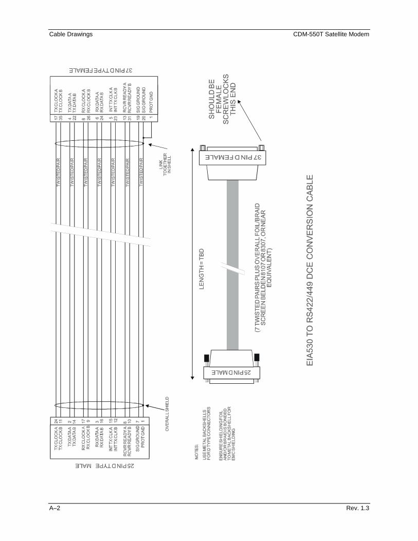
Cable Drawings CDM-550T Satellite Modem
A–2 Rev. 1.3
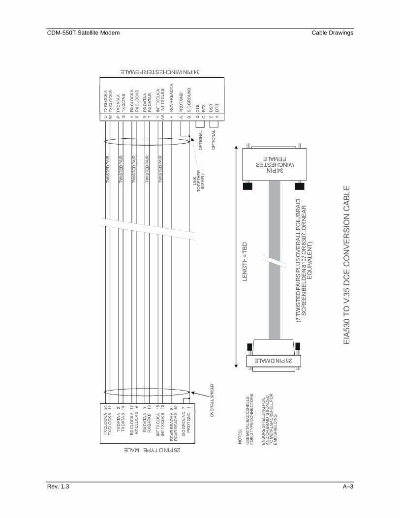
CDM-550T Satellite Modem Cable Drawings
Rev. 1.3 A–3
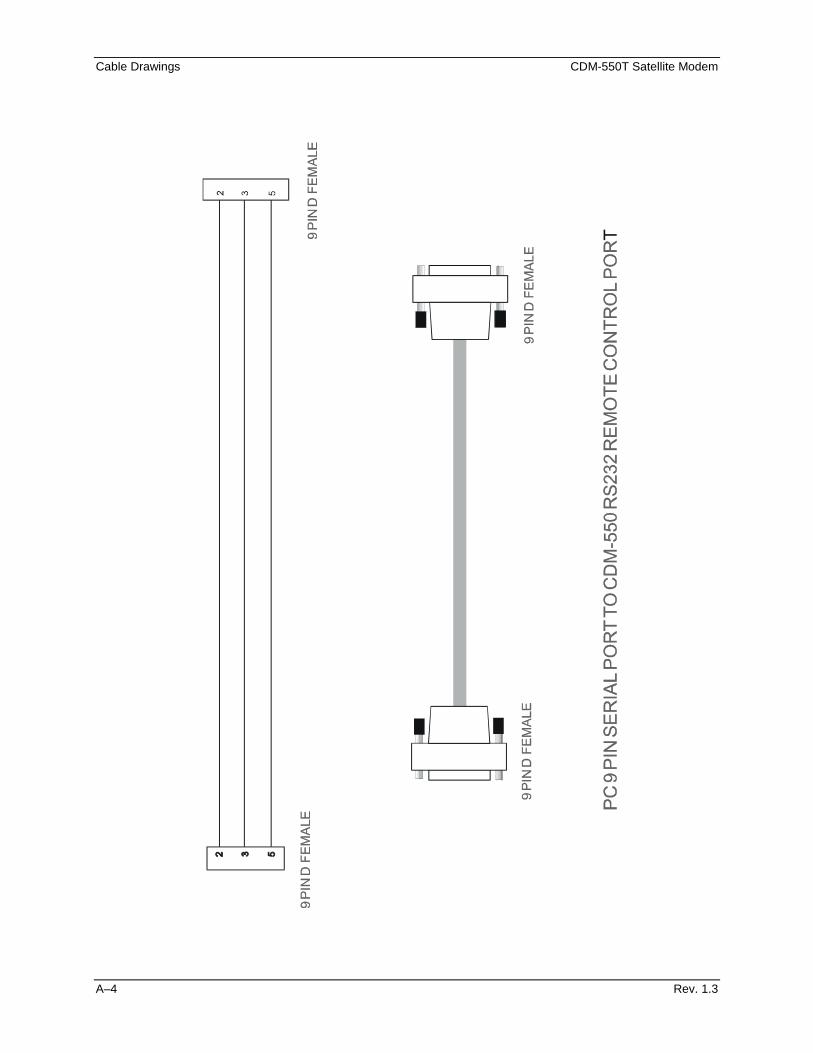
Cable Drawings CDM-550T Satellite Modem
A–4 Rev. 1.3
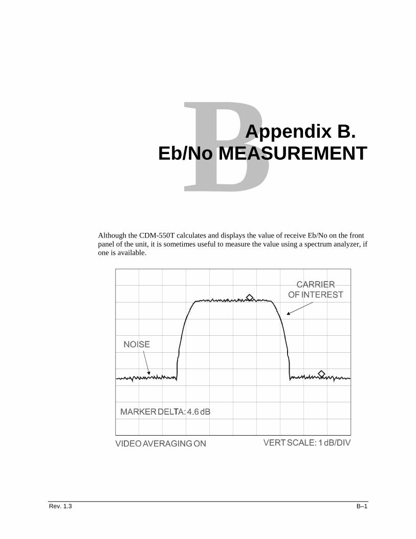
Rev. 1.3 B–1
B Appendix B. Eb/No MEASUREMENT
Although the CDM-550T calculates and displays the value of receive Eb/No on the front panel of the unit, it is sometimes useful to measure the value using a spectrum analyzer, if one is available.
Eb/No Measurement CDM-550T Satellite Modem
B–2 Rev. 1.3
The idea is to accurately measure the value of (C+N)/N, (Carrier + Noise/Noise) and this is accomplished by tuning the center frequency of the Spectrum analyzer to the signal of interest, and measuring the difference between the peak spectral density of the signal (the flat part of the spectrum shown) and the noise density. To make this measurement, use a vertical scale of 1 or 2 dB/division, and use video filtering and/or video averaging to reduce the variance in the displayed sweep to a low enough level that the difference can be measured to within 0.2dB. Use this value of (C+N)/N in the table on the following page to determine the Eb/No. You will need to know the operating mode to read from the appropriate column. In the diagram above, the (C+N)/N measured is 4.6 dB. If Rate 1/2 QPSK is being used, this would correspond to an Eb/No of approximately 2.6 dB.
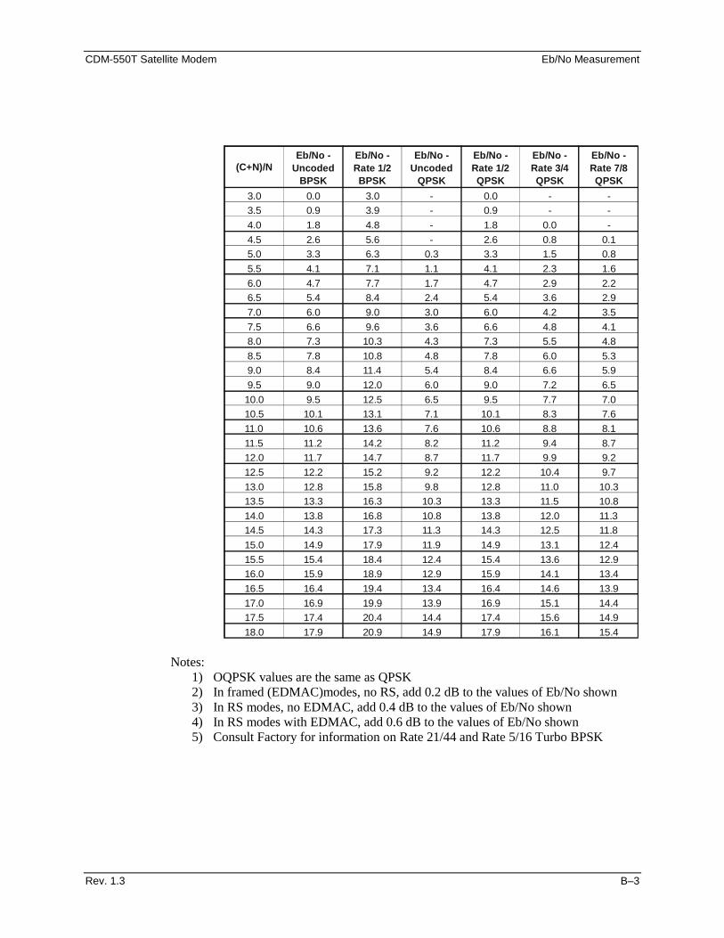
CDM-550T Satellite Modem Eb/No Measurement
Rev. 1.3 B–3
Notes:
1) OQPSK values are the same as QPSK 2) In framed (EDMAC)modes, no RS, add 0.2 dB to the values of Eb/No shown 3) In RS modes, no EDMAC, add 0.4 dB to the values of Eb/No shown 4) In RS modes with EDMAC, add 0.6 dB to the values of Eb/No shown 5) Consult Factory for information on Rate 21/44 and Rate 5/16 Turbo BPSK
(C+N)/NEb/No -
Uncoded BPSK
Eb/No - Rate 1/2 BPSK
Eb/No - Uncoded
QPSK
Eb/No - Rate 1/2 QPSK
Eb/No - Rate 3/4 QPSK
Eb/No - Rate 7/8 QPSK
3.0 0.0 3.0 - 0.0 - -3.5 0.9 3.9 - 0.9 - -4.0 1.8 4.8 - 1.8 0.0 -4.5 2.6 5.6 - 2.6 0.8 0.15.0 3.3 6.3 0.3 3.3 1.5 0.85.5 4.1 7.1 1.1 4.1 2.3 1.66.0 4.7 7.7 1.7 4.7 2.9 2.26.5 5.4 8.4 2.4 5.4 3.6 2.97.0 6.0 9.0 3.0 6.0 4.2 3.57.5 6.6 9.6 3.6 6.6 4.8 4.18.0 7.3 10.3 4.3 7.3 5.5 4.88.5 7.8 10.8 4.8 7.8 6.0 5.39.0 8.4 11.4 5.4 8.4 6.6 5.99.5 9.0 12.0 6.0 9.0 7.2 6.510.0 9.5 12.5 6.5 9.5 7.7 7.010.5 10.1 13.1 7.1 10.1 8.3 7.611.0 10.6 13.6 7.6 10.6 8.8 8.111.5 11.2 14.2 8.2 11.2 9.4 8.712.0 11.7 14.7 8.7 11.7 9.9 9.212.5 12.2 15.2 9.2 12.2 10.4 9.713.0 12.8 15.8 9.8 12.8 11.0 10.313.5 13.3 16.3 10.3 13.3 11.5 10.814.0 13.8 16.8 10.8 13.8 12.0 11.314.5 14.3 17.3 11.3 14.3 12.5 11.815.0 14.9 17.9 11.9 14.9 13.1 12.415.5 15.4 18.4 12.4 15.4 13.6 12.916.0 15.9 18.9 12.9 15.9 14.1 13.416.5 16.4 19.4 13.4 16.4 14.6 13.917.0 16.9 19.9 13.9 16.9 15.1 14.417.5 17.4 20.4 14.4 17.4 15.6 14.918.0 17.9 20.9 14.9 17.9 16.1 15.4

Eb/No Measurement CDM-550T Satellite Modem
B–4 Rev. 1.3
This page is intentionally left blank.
Rev. 1.3 C–1
CAppendix C. Async Overhead Option
Introduction For many applications the EDMAC channel provides an excellent solution to the problem of communicating with a modem (and possibly a transceiver) at the distant end of a satellite link. However, the EDMAC information remains internal to the equipment, and is not presented to the outside world. There are some applications where it may be useful to transfer async EIA-232 data over the satellite link, using the overhead channel, and provide external access. This could be used, for example, for controlling and monitoring external (non-Comtech) equipment, or perhaps for PC-to-PC file transfer.
Consequently, in Software Version 1.19 and later, a transparent async overhead mode has been added that provides this functionality. This mode uses the same frame format that EDMAC uses, and continues to add 5% to the transmitted bit rate.
In order to provide external access, without using the main Remote Control connector on the rear panel, the Auxiliary Serial connector is used. This is the small 3-pin connector found on the rear panel, to the left of the Remote Control connector. This is connected internally to a UART (independent of the UART used for normal remote control and EDMAC functions) which is normally used for inter-unit communications in a 1:1 pair, and for FSK communications with a Comtech Transceiver.
For these reasons, if the transparent Async Overhead mode is used, the following features are not available:
1) EDMAC is not available (the framing bytes reserved for EDMAC are now allocated to async transfer). 2) 1:1 inter-unit communications (the UART is now assigned to async transfer). 3) FSK communications with a Comtech Transceiver (the UART is now assigned to async transfer).
However, is should be noted that AUPC is still available in this mode.
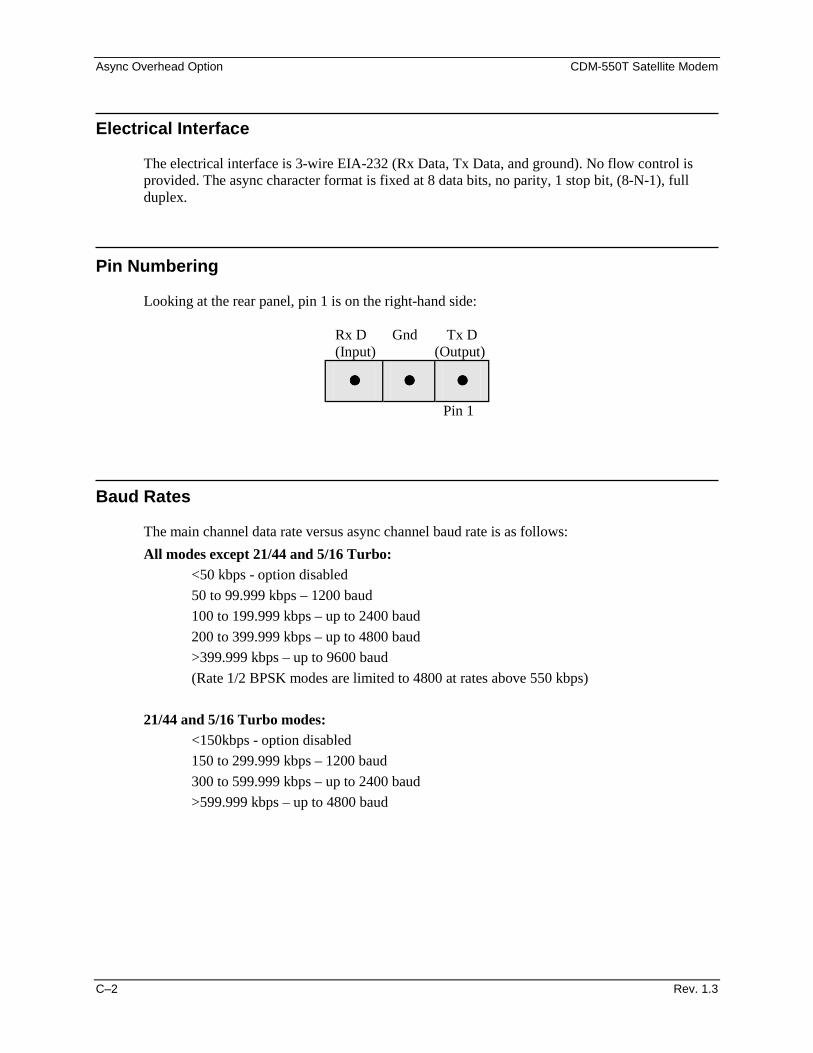
Async Overhead Option CDM-550T Satellite Modem
C–2 Rev. 1.3
Electrical Interface
The electrical interface is 3-wire EIA-232 (Rx Data, Tx Data, and ground). No flow control is provided. The async character format is fixed at 8 data bits, no parity, 1 stop bit, (8-N-1), full duplex.
Pin Numbering
Looking at the rear panel, pin 1 is on the right-hand side:
Rx D Gnd Tx D (Input) (Output)
•••• •••• •••• Pin 1
Baud Rates The main channel data rate versus async channel baud rate is as follows: All modes except 21/44 and 5/16 Turbo: <50 kbps - option disabled 50 to 99.999 kbps – 1200 baud 100 to 199.999 kbps – up to 2400 baud 200 to 399.999 kbps – up to 4800 baud >399.999 kbps – up to 9600 baud (Rate 1/2 BPSK modes are limited to 4800 at rates above 550 kbps) 21/44 and 5/16 Turbo modes: <150kbps - option disabled 150 to 299.999 kbps – 1200 baud 300 to 599.999 kbps – up to 2400 baud
>599.999 kbps – up to 4800 baud
CDM-550T Satellite Modem Async Overhead Option
Rev. 1.3 C–3
Selecting Async Mode
Access to this mode is not via the normal front panel menus or remote control. Customers wishing to order modems from the factory may request that their units be pre-configured to operate in this mode when they are shipped. Users who have existing units, and that have Software Version 1.19 installed, may select Transparent Async mode from the FACTORY, SPECIALS menu. The FACTORY sub-menus contain features and operating modes that may be specific to particular customers of Comtech EF Data, and includes diagnostic modes that may, in certain circumstances, render the modem inoperable. It is our policy, therefore to require a special combination of keystrokes for FACTORY access, which we do not publish. Therefore, if a customer wishes to select this mode, Customer Service should be contacted, who will then provide instructions on how to enter the FACTORY sub-menus.
Once the feature has been enabled, the user should select CONFIG, FRAME, select FRAMED, then press ENTER. The sub-menu that is then displayed will show the currently selected baud rate. The baud rate can then be modified using the UP/DOWN arrow keys, then pressing ENTER. When the sub-menu is first entered it will default to the highest possible baud rate, based on the current modulation, FEC type, and data rate. If these parameters are changed, such that the modem can no longer support the selected baud rate, the baudrate will be automatically modified to the highest possible value.
To disable the async mode, select CONFIG, FRAME, select TRANSPARENT, then press ENTER.

Async Overhead Option CDM-550T Satellite Modem
C–4 Rev. 1.3
This page is intentionally left blank.
Rev. 1.2 i–1
I Index
-A-
About this Manual ...................................................viii Address ................................................................. 15–3 Alarm.................................................................... 12–3 Alarms Connector - 15 Pin ‘D’ Type Male...........5–1 Approvals.............................................................. 14–5 Async Character Formats Using 1.5 Stop Bits........9–2 Async Overhead Option......................................... C–1 ASYNC EIA-232 Specifications ............................9–1 AUPC .....................................................................1–2 Automatic Uplink Power Control ........................ 12–1 Automatic Uplink Power Control ......................... 14–4 Auxiliary Serial Connector -
HE1402 3 Pin Header .....................................5–2
-B- Basic Protocol....................................................... 15–2 Baud Rate Accuracy ...............................................9–2 Buffer Disabled..................................................... 10–2 Buffer Enabled, RX<>TX..................................... 10–3 Buffer Enabled, RX=TX....................................... 10–2
-C- Cable Drawings ..................................................... A–1 Cautions and Warnings............................................viii Compatibility ..........................................................1–3 Compensation Rate............................................... 12–3 Comtech Efdata Turbo Product Codec Rate 3/4 QPK,
Rate 21/44 BPSK, Rate 5/16 BPSK.............. 7–15 Concatenated RS Coding Summary........................7–4 Config: ....................................................................6–5 Configuration..........................................................2–2 Connect External Cables.........................................2–2 Connector Pinouts...................................................5–1 Conventions and References....................................viii Customer Support .......................................................ii
-D- Data Connector - 25 Pin ‘D’ Type Female ...........5–1
Data Connector - 25 Pin ‘D’ Type Female ........... 5–1 Data Interfaces ....................................................... 1–3 Data Interfaces ......................................................14–4 Demod Unlock ......................................................12–3 Demodulator Specifications ..................................14–2 Differential Encoding No FEC ............................7–16 Disclaimer ................................................................ xii
-E- Eb/No Measurement...............................................B–1 EDMAC Theory Of Operation..............................11–1 EIA-232 Data Interface -
Asynchronous Operation................................ 9–1 EIA-232.................................................................15–2 EIA-485.................................................................15–1 Electrical Safety ........................................................ ix EMC (Electromagnetic Compatibility) .......................x End Of Packet .......................................................15–5 End-to-End Processing Delay ................................ 7–6 Environmental ........................................................... ix Exclusive Remedies ................................................. xii External Clock.......................................................10–1
-F- Flash Upgrading....................................................13–1 Forward Error Correction Options ........................ 7–1 Front And Rear Panel............................................. 4–1 Front Panel Description.......................................... 6–1 Front Panel Led Indicators ..................................... 4–2 Front Panel ............................................................. 4–2 Functional Description ........................................... 3–1 Fuses ......................................................................... ix
-I- INFO (Information)...............................................6–30 Installation...................................................................x Instruction Code Qualifier.....................................15–4 Instruction Code....................................................15–4 Internal Clock........................................................10–1 Introduction...........................................................15–1
Index CDM-550T Satellite Modem
i–2 Rev. 1.2
-L- Limitations of Warranty............................................xii Loop Timing With Sync EIA-232 ........................ 10–3 Loop-Timed, RX<>TX
(Asymmetric Loop Timing) .......................... 10–2 Loop-Timed, RX=TX ........................................... 10–2
-M- M&C Connection.................................................. 11–2 Max Range............................................................ 12–2 Menu Trees .............................................................6–2 Message Arguments.............................................. 15–5 Metric Conversion ...................................................viii Miscellaneous ....................................................... 14–4 Modulator Specifications...................................... 14–1 MONIT (Monitor) ................................................ 6–33 Monitoring............................................................ 12–4 Mounting ................................................................2–1
-N- New in This Release ...............................................1–4
-O- Offset QPSK Operation ..........................................8–1 Opening Screen.......................................................6–2 Options ...................................................................1–3 Other Considerations ..............................................9–2 Overview of Changes to Previous Edition ...............viii
-P- Packet Structure .................................................... 15–3
-R- Rear Panel...............................................................4–3 Receive Clocking.................................................. 10–2 Recommended Standard Designations.....................viii Reed-Solomon Outer Codec (Option).....................7–3 Remote Control Connector -
9 Pin ‘D’ Type Male .......................................5–1 Remote Control Connector -
9 Pin ‘D’ Type Male .......................................5–1 Remote control ..................................................... 15–1 Reporting Comments or Suggestions Concerning
this Manual ........................................................ ix RF Loopback .........................................................6-28 RX Clock Modes .................................................. 10–5
-S- Safety Notices ........................................................... ix Select Internal IF Loop........................................... 2–2 Select...................................................................... 6–4 Sequential Decoding 64 Kbps .............................7–10 Sequential Decoding 1024 Kbps ..........................7–11 Sequential Decoding 2048 Kbps ..........................7–12 Sequential Decoding Summary .............................. 7–3 Sequential............................................................... 7–2 Setting AUPC Parameters .....................................12–2 Setup Summary .....................................................11–3 Setup ...................................................................... 9–2 Software ................................................................. 1–2 Standard Features ................................................... 1–1 Start Of Packet ......................................................15–3 STORE/LD (Store/Load) ......................................6–38 Summary of Specifications ..................................14–1
-T- Target Eb/No.........................................................12–2 Telecommunications Terminal Equipment
Directive..............................................................x TEST.....................................................................6–28 Transmit Clocking.................................................10–1 Turbo Product Codec (Option)............................... 7–4 TX CLOCK MODES............................................10–4
-U- Uncoded Operation (No FEC)................................ 7–7 Unpacking .............................................................. 2–1 UTIL (Utility)........................................................6–41
-V- Verification ............................................................ 1–2 Viterbi Decoding Summary.................................... 7–2 Viterbi Decoding.................................................... 7–9 Viterbi With Concatenated RS 2200,200
Outer Code ...................................................7–13 Viterbi With Concatenated RS 2200,200
Outer Code 512 Kbps ...................................7–14 Viterbi .................................................................... 7–1 Warranty Policy ....................................................... xii
-X- X.21 Notes ............................................................10–3

CDM-550T Satellite Modem
Monitor and Control of the KST-2000A Satellite TerminalAddendum A
(For Modem Firmware V1.20 or higher)Part # MN/CDM550T.AA1

Disclaimer
Comtech EF Data has reviewed this Addendum thoroughly in order that it will be an easy-to-use guide to your equipment. All statements, technical information, and recommendations in this manual and in any guides or related documents are believed reliable, but the accuracy and completeness thereof are not guaranteed or warranted, and they are not intended to be, nor should they be understood to be, representations or warranties concerning the products described. Further, Comtech EF Data reserves the right to make changes in the specifications of the products described in this supplement at any time without notice and without obligation to notify any person of such changes. If you have any questions regarding your equipment or the information in this document, please contact the Comtech EF Data Customer Support Department.

CDM-550T Satellite Modem Table of Contents Revision 0 i
Table of Contents
ODU Operation via a CDM-550T Modem Front Panel Comprising Firmware ≥≥≥≥ 1.20 ........................................ 1
Menu Trees .................................................................................................................................................................. 3
Select ............................................................................................................................................................................ 3
ODU.............................................................................................................................................................................. 3
(ODU,ENABLE) Selections...................................................................................................................................... 4
(ODU,ENABLE) CONFIG (Configuration) .......................................................................................................... 4
(ODU,ENABLE,CONFIG) TRANSMITTER ........................................................................................................ 4
(ODU,ENABLE,CONFIG,TRANSMITTER) FREQUENCY .............................................................................. 4
(ODU,ENABLE,CONFIG,TRANSMITTER) ATTEN (Attenuation).................................................................. 5
(ODU,ENABLE,CONFIG,TRANSMITTER) OUTPUT....................................................................................... 5
(ODU,ENABLE,CONFIG,TRANSMITTER) HPA............................................................................................... 5
(ODU,ENABLE,CONFIG,TRANSMITTER) STATE .......................................................................................... 5
(ODU,ENABLE,CONFIG,TRANSMITTER) SUMMARY .................................................................................. 5
(ODU,ENABLE,CONFIG) RECEIVER................................................................................................................ 6
(ODU,ENABLE,CONFIG,RECEIVER) FREQUENCY....................................................................................... 6
(ODU,ENABLE,CONFIG,RECEIVER) ATTEN (Attenuation) .......................................................................... 7
(ODU,ENABLE,CONFIG,RECEIVER) LNA ....................................................................................................... 7
CDM-550T Satellite Modem Table of Contents Revision 0 ii
(ODU,ENABLE,CONFIG,RECEIVER,LNA) STATE ......................................................................................... 7
(ODU,ENABLE,CONFIG,RECEIVER,LNA) CAL (Calibration)...................................................................... 7
(ODU,ENABLE,CONFIG,RECEIVER,LNA) FAULT-LOGIC .......................................................................... 7
(ODU,ENABLE,CONFIG) MISCELLANEOUS................................................................................................... 8
(ODU,ENABLE,CONFIG,MISCELLANEOUS) AGC (AUTO GAIN CONTROL) ......................................... 8
(ODU,ENABLE,CONFIG,MISCELLANEOUS) REF-ADJUST ......................................................................... 8
(ODU,ENABLE) INFO (Information) .................................................................................................................... 8
(ODU,ENABLE,INFO) TRANSMITTER .............................................................................................................. 9
(ODU,ENABLE,INFO) RECEIVER....................................................................................................................... 9
(ODU,ENABLE,INFO) HPA ................................................................................................................................... 9
(ODU,ENABLE,INFO) LNA ................................................................................................................................... 9
(ODU,ENABLE,INFO) EQUIP (Equipment)......................................................................................................... 9
(ODU,ENABLE,INFO) ASSEMBLY + SN............................................................................................................. 9
(ODU,ENABLE,INFO) FW (Firmware)............................................................................................................... 10
(ODU,ENABLE) STATUS ..................................................................................................................................... 10
MN/CDM550T.AA11
KST-2000A FSK REMOTE
OPERATION
1.1 ODU Operation via a CDM-550T Modem Front Panel Comprising Firmware ≥≥≥≥ 1.20
This addendum incorporates the menus that are displayed on the CDM-550T modem’s front panel for control of monitoring and control of the KST-2000A Satellite Terminal. The user can fully control and monitor the operation of Comtech EF Data’s KST-2000A Satellite Terminal from the front panel, using the keypad and display of a CDM-550T modem. Nested menus display all available options and prompt the user for required actions. The display has two lines each of 24 characters. On most menu screens, a flashing solid block cursor blinks once per second to indicate the currently selected item, digit, or field. Where this solid block cursor would obscure the item being edited (for example, a numeric field) the cursor will automatically change to an underline cursor.
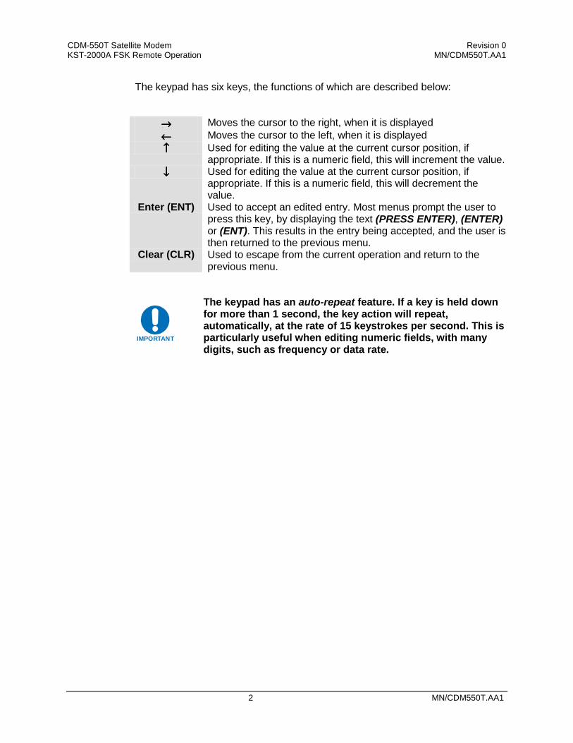
CDM-550T Satellite Modem Revision 0 KST-2000A FSK Remote Operation MN/CDM550T.AA1
2 MN/CDM550T.AA1
The keypad has six keys, the functions of which are described below:
→→→→ Moves the cursor to the right, when it is displayed ←←←← Moves the cursor to the left, when it is displayed ↑↑↑↑ Used for editing the value at the current cursor position, if
appropriate. If this is a numeric field, this will increment the value. ↓↓↓↓ Used for editing the value at the current cursor position, if
appropriate. If this is a numeric field, this will decrement the value.
Enter (ENT) Used to accept an edited entry. Most menus prompt the user to press this key, by displaying the text (PRESS ENTER), (ENTER) or (ENT). This results in the entry being accepted, and the user is then returned to the previous menu.
Clear (CLR) Used to escape from the current operation and return to the previous menu.
IMPORTANT
The keypad has an auto-repeat feature. If a key is held down for more than 1 second, the key action will repeat, automatically, at the rate of 15 keystrokes per second. This is particularly useful when editing numeric fields, with many digits, such as frequency or data rate.

CDM-550T Satellite Modem Revision 0 KST-2000A FSK Remote Operation MN/CDM550T.AA1
MN/CDM550T.AA1 3
1.2 Menu Trees
1.2.1 SELECT
SELECT: CONFIG TEST INFO MONIT STORE/LD UTIL ODU
The user is presented with the following choices: CONFIG (Configuration) This menu branch permits the user to fully configure the modem.
TEST This menu branch permits the user invoke one of several modem test modes (loopbacks, for example).
INFO (Information) This menu branch permits the user to view information on the modem, without having to go into configuration screens.
MONIT (Monitor) This menu branch permits the user to monitor the alarm status of the modem, to view the log of stored events, and to display the Receive Parameters screen.
STORE/LD (Store/Load) This menu branch permits the user to store and to retrieve up to 10 different modem configurations.
UTIL (Utility) This menu branch permits the user to perform miscellaneous modem functions, such as setting the Real-time clock, adjusting the display brightness, etc.
ODU (Outdoor Unit) This permits the user to monitor and control a Comtech EF Data KST-2000A Transceiver, if connected.
The first six items are covered in the existing modem manuals. The ODU item is now described in detail.
1.2.2 ODU
TRANSCEIVER CONTROL: DISABLE ENABLE (ENTER)
DISABLE This menu item turns OFF the FSK link to the ODU ENABLE This menu item turns ON the FSK link to the ODU
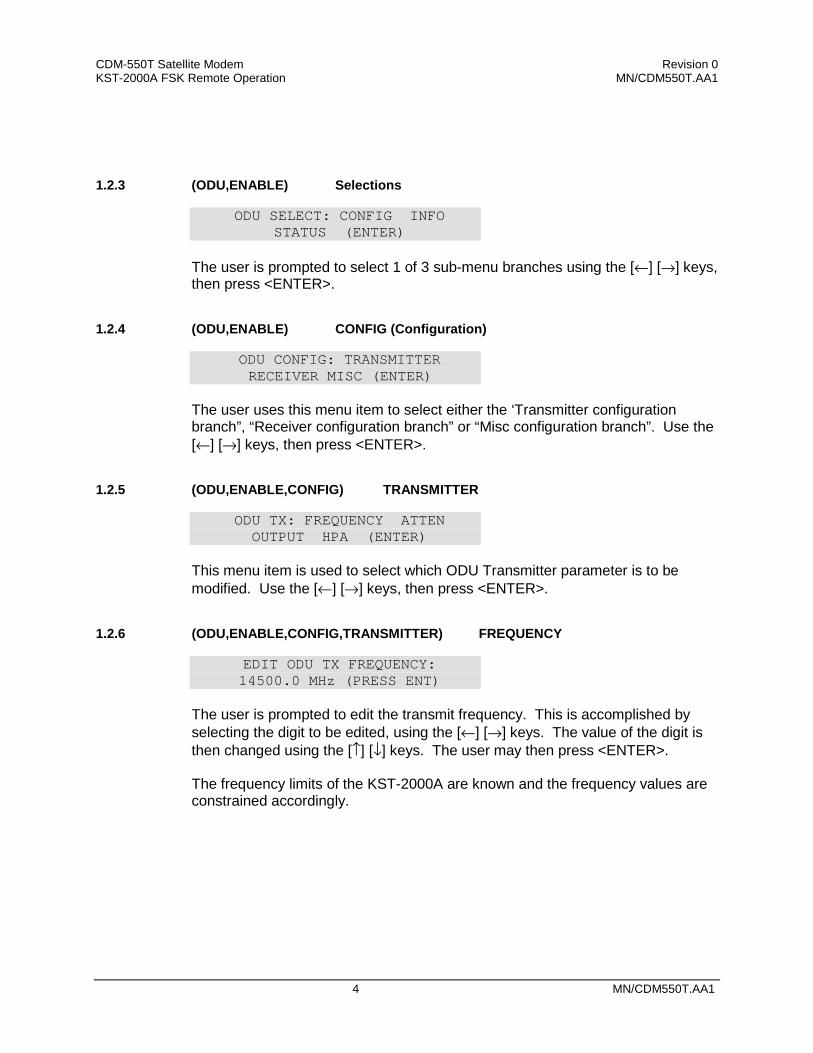
CDM-550T Satellite Modem Revision 0 KST-2000A FSK Remote Operation MN/CDM550T.AA1
4 MN/CDM550T.AA1
1.2.3 (ODU,ENABLE) Selections
ODU SELECT: CONFIG INFO STATUS (ENTER)
The user is prompted to select 1 of 3 sub-menu branches using the [←] [→] keys, then press <ENTER>.
1.2.4 (ODU,ENABLE) CONFIG (Configuration)
ODU CONFIG: TRANSMITTER RECEIVER MISC (ENTER)
The user uses this menu item to select either the ‘Transmitter configuration branch”, “Receiver configuration branch” or “Misc configuration branch”. Use the [←] [→] keys, then press <ENTER>.
1.2.5 (ODU,ENABLE,CONFIG) TRANSMITTER
ODU TX: FREQUENCY ATTEN OUTPUT HPA (ENTER)
This menu item is used to select which ODU Transmitter parameter is to be modified. Use the [←] [→] keys, then press <ENTER>.
1.2.6 (ODU,ENABLE,CONFIG,TRANSMITTER) FREQUENCY
EDIT ODU TX FREQUENCY: 14500.0 MHz (PRESS ENT)
The user is prompted to edit the transmit frequency. This is accomplished by selecting the digit to be edited, using the [←] [→] keys. The value of the digit is then changed using the [↑] [↓] keys. The user may then press <ENTER>. The frequency limits of the KST-2000A are known and the frequency values are constrained accordingly.

CDM-550T Satellite Modem Revision 0 KST-2000A FSK Remote Operation MN/CDM550T.AA1
MN/CDM550T.AA1 5
1.2.7 (ODU,ENABLE, CONFIG,TRANSMITTER) ATTEN (Attenuation)
EDIT ODU TX ATTENUATION: 15.00 dB (PRESS ENTER)
The user is prompted to edit the transmit attenuation. This is accomplished by selecting the digit to be edited, using the [←] [→] keys. The value of the digit is then changed using the [↑] [↓] keys. The user then presses <ENTER>.
1.2.8 (ODU,ENABLE,CONFIG,TRANSMITTER) OUTPUT
SELECT KST TX OUTPUT: OFF ON WARM (ENTER)
The user is prompted to select either ON, OFF, or WARM using the [←] [→] keys, then press <ENTER>.
• WARM is OFF, if COLD. • WARM is ON, if warm and NO FAULTS • FAULTS present, stays WARM and OFF indefinitely
1.2.9 (ODU,ENABLE,CONFIG,TRANSMITTER) HPA
CONFIG HPA: STATE FAULT-LOGIC (ENTER)
1.2.10 (ODU, ENABLE,CONFIG,TRANSMITTER) STATE
SELECT KST HPA STATE: ON OFF (PRESS ENTER)
1.2.11 (ODU,ENABLE,CONFIG, TRANSMITTER) FAULT-LOGIC
SELECT HPA FAULT LOGIC: SUMMARY NO-SUMM (ENTER)
The user may select from the options shown, using the [←] [→] keys, then press <ENTER>.
Note: If the HPA power is OFF, it cannot report errors, answer messages, provide serial numbers, etc.
CDM-550T Satellite Modem Revision 0 KST-2000A FSK Remote Operation MN/CDM550T.AA1
6 MN/CDM550T.AA1
1.2.12 (ODU,ENABLE, CONFIG) RECEIVER
ODU RX: FREQUENCY ATTEN LNA (PRESS ENTER)
This menu item is used to select which ODU Receiver parameter is to be modified. Use the [←] [→] keys, then press <ENTER>.
1.2.13 (ODU,ENABLE, CONFIG,RECEIVER) FREQUENCY
EDIT ODU RX FREQUENCY: 10950.0 MHz (PRESS ENT)
The user is prompted to edit the receive frequency. This is accomplished by selecting the digit to be edited, using the [←] [→] keys. The value of the digit is then changed using the [↑] [↓] keys. The user may then press <ENTER>.
CDM-550T Satellite Modem Revision 0 KST-2000A FSK Remote Operation MN/CDM550T.AA1
MN/CDM550T.AA1 7
1.2.14 (ODU,ENABLE, CONFIG,RECEIVER) ATTEN (Attenuation)
EDIT ODU RX ATTENUATION: 15.00 dB (PRESS ENTER)
The user is prompted to edit the receive attenuation. This is accomplished by selecting the digit to be edited, using the [←] [→] keys. The value of the digit is then changed using the [↑] [↓] keys. The user then presses <ENTER>.
1.2.15 (ODU,ENABLE, CONFIG,RECEIVER) LNA
SELECT LNA: STATE CAL FAULT-LOGIC (ENTER)
The user may select a parameter using the [←] [→] keys, then press <ENTER>.
1.2.16 (ODU,ENABLE, CONFIG,RECEIVER,LNA) STATE
SELECT ODU LNA STATE: ON OFF (PRESS ENTER)
The user is prompted to select either ON or OFF, using the [←] [→] keys, then to press <ENTER>. This controls whether or not the ODU will provide LNA POWER via the Receive RF Cable.
1.2.17 (ODU,ENABLE, CONFIG,RECEIVER,LNA) CAL (Calibrate)
CALIBRATE LNA CURRENT? CAL EXIT (PRESS ENTER)
The user is prompted to select either CAL or EXIT, using the [←] [→] keys, then to press <ENTER>. Calibration allows the system to determine nominal LNA power consumption. This need only be performed at initial installation.
1.2.18 (ODU,ENABLE, CONFIG,RECEIVER,LNA) FAULT-LOGIC
SELECT LNA FAULT LOGIC: SUMMARY NO–SUMM (ENTER)
The user is prompted to select either SUMMARY or NO SUMM, using the [←] [→] keys, then to press <ENTER>. This controls whether or not LNA fault will activate the SUMMARY FAULT RELAY.
CDM-550T Satellite Modem Revision 0 KST-2000A FSK Remote Operation MN/CDM550T.AA1
8 MN/CDM550T.AA1
1.2.19 (ODU,ENABLE, CONFIG) MISCELLANEOUS
KST MISC: AGC REF-ADJUST (ENTER)
This menu item is used to select miscellaneous ODU parameters for modification. Use the [←] [→] keys, then press <ENTER>.
1.2.20 (ODU,ENABLE,CONFIG,MISCELLANEOUS) AGC (Auto Gain Control)
SEL AGC MODE: OFF ON BURST (ENTER)
The user is prompted to select either OFF, ON or BURST, using the [←] [→] keys, then to press <ENTER>.
1.2.21 (ODU,ENABLE,CONFIG,MISCELLANEOUS) REF-ADJUST
EDIT INT REF ADJUSTMENT: 028 (PRESS ENTER) The user is prompted to edit the INT 10MHz REF setting using the [↑] [↓] keys, then to press <ENTER>. The value will scroll between 000 and 255. Note: The INT REF is adjusted in the factory to be very accurate with the default setting of 028. This parameter is made available to compensate for the long-term frequency drift of the oscillator.
1.2.22 (ODU,ENABLE) INFO (Information)
INFO: TX RX HPA LNA EQUIP ASSEMBLY+SN FW (ENTER)
The operator uses this menu item to select enter 1 of 7 ‘Information Windows’. Use the [←] [→] keys, then press <ENTER>.

CDM-550T Satellite Modem Revision 0 KST-2000A FSK Remote Operation MN/CDM550T.AA1
MN/CDM550T.AA1 9
1.2.23 (ODU,ENABLE,INFO) TRANSMITTER
TX: ON 14500.0 MHz 19dB AGC: OFF This window provides the KST-2000A Transmitter information including Tx Frequency, and Tx Attenuation, press <ENTER>or <CLEAR>.
1.2.24 (ODU,ENABLE, INFO) RECEIVER
RX: 10950.0 MHz 15dB REF:228 This window provides the KST-2000A Receiver information including Rx Frequency, and Rx Attenuation, press <ENTER>.
1.2.25 (ODU,ENABLE, INFO) HPA
HPA = ON FAULT LOGIC = NO SUMMARY
1.2.26 (ODU,ENABLE, INFO) LNA
LNA: ON FAULT LOGIC: NO SUMMARY
This window provides the current configuration of the LNA functions, press <ENTER>.
1.2.27 (ODU,ENABLE,INFO) EQUIP (Equipment)
EQUIP-TYPE: KST-2000A HPA-TYPE: CEFD-SSPA
1.2.28 (ODU,ENABLE,INFO) ASSEMBLY+SN
ASSEMBLY INFO: M&C AS: 11565-4 SN: 001370891 Note: The blinking cursor is on the M&C. Use the [↑] [↓] keys to view additional assembly and S/N information for the Up Converter, Down Converter, and HPA.

CDM-550T Satellite Modem Revision 0 KST-2000A FSK Remote Operation MN/CDM550T.AA1
10 MN/CDM550T.AA1
1.2.29 ODU,ENABLE,INFO) FW (Firmware)
FIRMWARE INFO: M&C FW: 9364-1- VER: 01.01.01 Note: The blinking cursor is on the M&C. Use the [↑] [↓] keys to view additional firmware information for the Up Converter, Down Converter, and HPA.
1.2.30 (ODU,ENABLE) STATUS
STATUS: PS:OK RF:OK UC:OK LNA:OK AG:OK HP:OK DC:OK This menu displays summary information. The operator may select 1 of 6 detailed status windows. Use the [←] [→] keys, then press <ENTER>. The cursor may be moved over 6 of the 7 status parameters to view more detailed status information. These screens are continually updated while being viewed. AG = AGC Status DC = Down Converter HP = HPA Status LNA = Low Noise Amplifier (No further detail) PS = Power Supplies RF = Reference UC = Up Converter
FT = Fault NA = Not Applicable OK = OK – No Fault
P/Supplies: 7V:OK 17V:OK -7V:OK 12V:OK
REF: WARM 72M:OK RANGE:NA SRC:INT XLK:NA PHASE:NA
UPCONV STATUS: OVRTMP:OK SSYN:OK KSYN:OK PRG:OK
AGC STATUS: EIP:OK LOOP:OK IIP:OK
HPA: OVERTEMP:OK 9.75V:OK
-5V:OK BIAS:OK PRG:OK
DNCONV STATUS: OVRTMP:OK LSYN:OK KSYN:OK PRG:OK
CDM-550T Satellite Modem
Monitor and Control of the KST-2000A Satellite TerminalAddendum A
(For Modem Firmware V1.20 or higher)Part # MN/CDM550T.AA1
Disclaimer
Comtech EF Data has reviewed this Addendum thoroughly in order that it will be an easy-to-use guide to your equipment. All statements, technical information, and recommendations in this manual and in any guides or related documents are believed reliable, but the accuracy and completeness thereof are not guaranteed or warranted, and they are not intended to be, nor should they be understood to be, representations or warranties concerning the products described. Further, Comtech EF Data reserves the right to make changes in the specifications of the products described in this supplement at any time without notice and without obligation to notify any person of such changes. If you have any questions regarding your equipment or the information in this document, please contact the Comtech EF Data Customer Support Department.
CDM-550T Satellite Modem Table of Contents Revision 0 i
Table of Contents
ODU Operation via a CDM-550T Modem Front Panel Comprising Firmware ≥≥≥≥ 1.20 .........................................1
Menu Trees...................................................................................................................................................................3
Select .............................................................................................................................................................................3
ODU ..............................................................................................................................................................................3
(ODU,ENABLE) Selections ......................................................................................................................................4
(ODU,ENABLE) CONFIG (Configuration) ...........................................................................................................4
(ODU,ENABLE,CONFIG) TRANSMITTER.........................................................................................................4
(ODU,ENABLE,CONFIG,TRANSMITTER) FREQUENCY...............................................................................4
(ODU,ENABLE,CONFIG,TRANSMITTER) ATTEN (Attenuation) ..................................................................5
(ODU,ENABLE,CONFIG,TRANSMITTER) OUTPUT .......................................................................................5
(ODU,ENABLE,CONFIG,TRANSMITTER) HPA ...............................................................................................5
(ODU,ENABLE,CONFIG,TRANSMITTER) STATE...........................................................................................5
(ODU,ENABLE,CONFIG,TRANSMITTER) SUMMARY...................................................................................5
(ODU,ENABLE,CONFIG) RECEIVER ................................................................................................................6
(ODU,ENABLE,CONFIG,RECEIVER) FREQUENCY .......................................................................................6
(ODU,ENABLE,CONFIG,RECEIVER) ATTEN (Attenuation)...........................................................................7
(ODU,ENABLE,CONFIG,RECEIVER) LNA ........................................................................................................7

CDM-550T Satellite Modem Table of Contents Revision 0 ii
(ODU,ENABLE,CONFIG,RECEIVER,LNA) STATE ..........................................................................................7
(ODU,ENABLE,CONFIG,RECEIVER,LNA) CAL (Calibration) ......................................................................7
(ODU,ENABLE,CONFIG,RECEIVER,LNA) FAULT-LOGIC ...........................................................................7
(ODU,ENABLE,CONFIG) MISCELLANEOUS ...................................................................................................8
(ODU,ENABLE,CONFIG,MISCELLANEOUS) AGC (AUTO GAIN CONTROL) .........................................8
(ODU,ENABLE,CONFIG,MISCELLANEOUS) REF-ADJUST..........................................................................8
(ODU,ENABLE) INFO (Information) .....................................................................................................................8
(ODU,ENABLE,INFO) TRANSMITTER...............................................................................................................9
(ODU,ENABLE,INFO) RECEIVER .......................................................................................................................9
(ODU,ENABLE,INFO) HPA....................................................................................................................................9
(ODU,ENABLE,INFO) LNA....................................................................................................................................9
(ODU,ENABLE,INFO) EQUIP (Equipment) .........................................................................................................9
(ODU,ENABLE,INFO) ASSEMBLY + SN .............................................................................................................9
(ODU,ENABLE,INFO) FW (Firmware) ...............................................................................................................10
(ODU,ENABLE) STATUS......................................................................................................................................10

MN/CDM550T.AA11
KST-2000A FSK REMOTE
OPERATION
1.1 ODU Operation via a CDM-550T Modem Front Panel Comprising Firmware ≥≥≥≥ 1.20
This addendum incorporates the menus that are displayed on the CDM-550T modem’s front panel for control of monitoring and control of the KST-2000A Satellite Terminal. The user can fully control and monitor the operation of Comtech EF Data’s KST-2000A Satellite Terminal from the front panel, using the keypad and display of a CDM-550T modem. Nested menus display all available options and prompt the user for required actions. The display has two lines each of 24 characters. On most menu screens, a flashing solid block cursor blinks once per second to indicate the currently selected item, digit, or field. Where this solid block cursor would obscure the item being edited (for example, a numeric field) the cursor will automatically change to an underline cursor.

CDM-550T Satellite Modem Revision 0 KST-2000A FSK Remote Operation MN/CDM550T.AA1
2 MN/CDM550T.AA1
The keypad has six keys, the functions of which are described below:
→→→→ Moves the cursor to the right, when it is displayed ←←←← Moves the cursor to the left, when it is displayed ↑↑↑↑ Used for editing the value at the current cursor position, if
appropriate. If this is a numeric field, this will increment the value. ↓↓↓↓ Used for editing the value at the current cursor position, if
appropriate. If this is a numeric field, this will decrement the value.
Enter (ENT) Used to accept an edited entry. Most menus prompt the user to press this key, by displaying the text (PRESS ENTER), (ENTER) or (ENT). This results in the entry being accepted, and the user is then returned to the previous menu.
Clear (CLR) Used to escape from the current operation and return to the previous menu.
IMPORTANT
The keypad has an auto-repeat feature. If a key is held down for more than 1 second, the key action will repeat, automatically, at the rate of 15 keystrokes per second. This is particularly useful when editing numeric fields, with many digits, such as frequency or data rate.
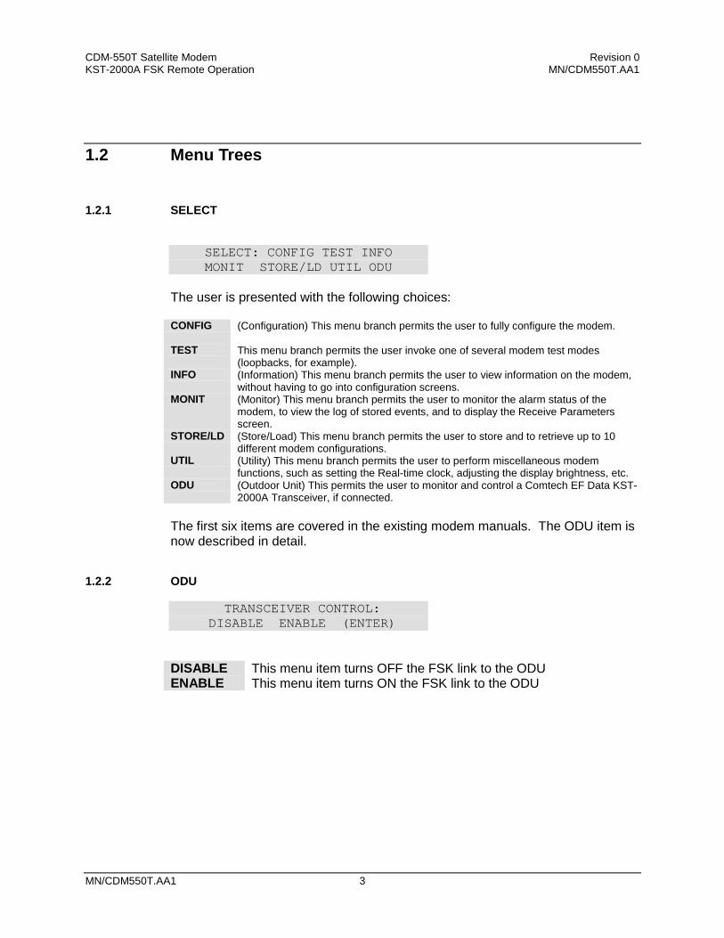
CDM-550T Satellite Modem Revision 0 KST-2000A FSK Remote Operation MN/CDM550T.AA1
MN/CDM550T.AA1 3
1.2 Menu Trees
1.2.1 SELECT
SELECT: CONFIG TEST INFO MONIT STORE/LD UTIL ODU
The user is presented with the following choices: CONFIG (Configuration) This menu branch permits the user to fully configure the modem.
TEST This menu branch permits the user invoke one of several modem test modes (loopbacks, for example).
INFO (Information) This menu branch permits the user to view information on the modem, without having to go into configuration screens.
MONIT (Monitor) This menu branch permits the user to monitor the alarm status of the modem, to view the log of stored events, and to display the Receive Parameters screen.
STORE/LD (Store/Load) This menu branch permits the user to store and to retrieve up to 10 different modem configurations.
UTIL (Utility) This menu branch permits the user to perform miscellaneous modem functions, such as setting the Real-time clock, adjusting the display brightness, etc.
ODU (Outdoor Unit) This permits the user to monitor and control a Comtech EF Data KST-2000A Transceiver, if connected.
The first six items are covered in the existing modem manuals. The ODU item is now described in detail.
1.2.2 ODU
TRANSCEIVER CONTROL: DISABLE ENABLE (ENTER)
DISABLE This menu item turns OFF the FSK link to the ODU ENABLE This menu item turns ON the FSK link to the ODU
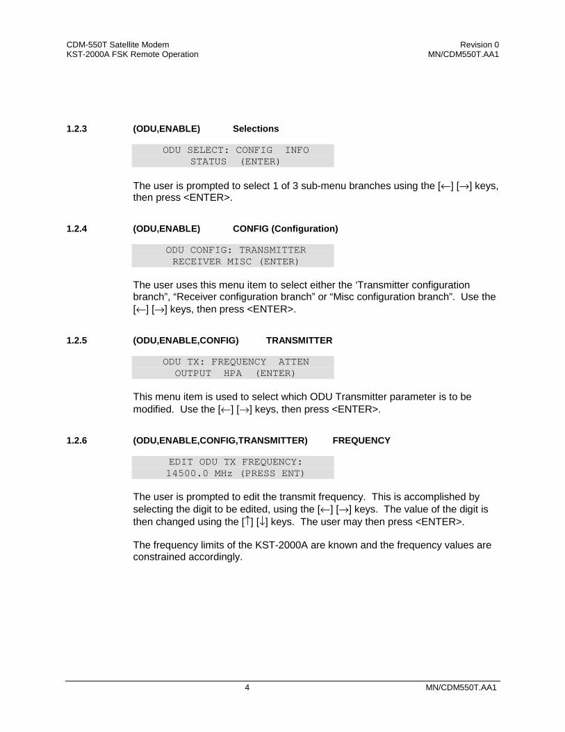
CDM-550T Satellite Modem Revision 0 KST-2000A FSK Remote Operation MN/CDM550T.AA1
4 MN/CDM550T.AA1
1.2.3 (ODU,ENABLE) Selections
ODU SELECT: CONFIG INFO STATUS (ENTER)
The user is prompted to select 1 of 3 sub-menu branches using the [←] [→] keys, then press <ENTER>.
1.2.4 (ODU,ENABLE) CONFIG (Configuration)
ODU CONFIG: TRANSMITTER RECEIVER MISC (ENTER)
The user uses this menu item to select either the ‘Transmitter configuration branch”, “Receiver configuration branch” or “Misc configuration branch”. Use the [←] [→] keys, then press <ENTER>.
1.2.5 (ODU,ENABLE,CONFIG) TRANSMITTER
ODU TX: FREQUENCY ATTEN OUTPUT HPA (ENTER)
This menu item is used to select which ODU Transmitter parameter is to be modified. Use the [←] [→] keys, then press <ENTER>.
1.2.6 (ODU,ENABLE,CONFIG,TRANSMITTER) FREQUENCY
EDIT ODU TX FREQUENCY: 14500.0 MHz (PRESS ENT)
The user is prompted to edit the transmit frequency. This is accomplished by selecting the digit to be edited, using the [←] [→] keys. The value of the digit is then changed using the [↑] [↓] keys. The user may then press <ENTER>. The frequency limits of the KST-2000A are known and the frequency values are constrained accordingly.
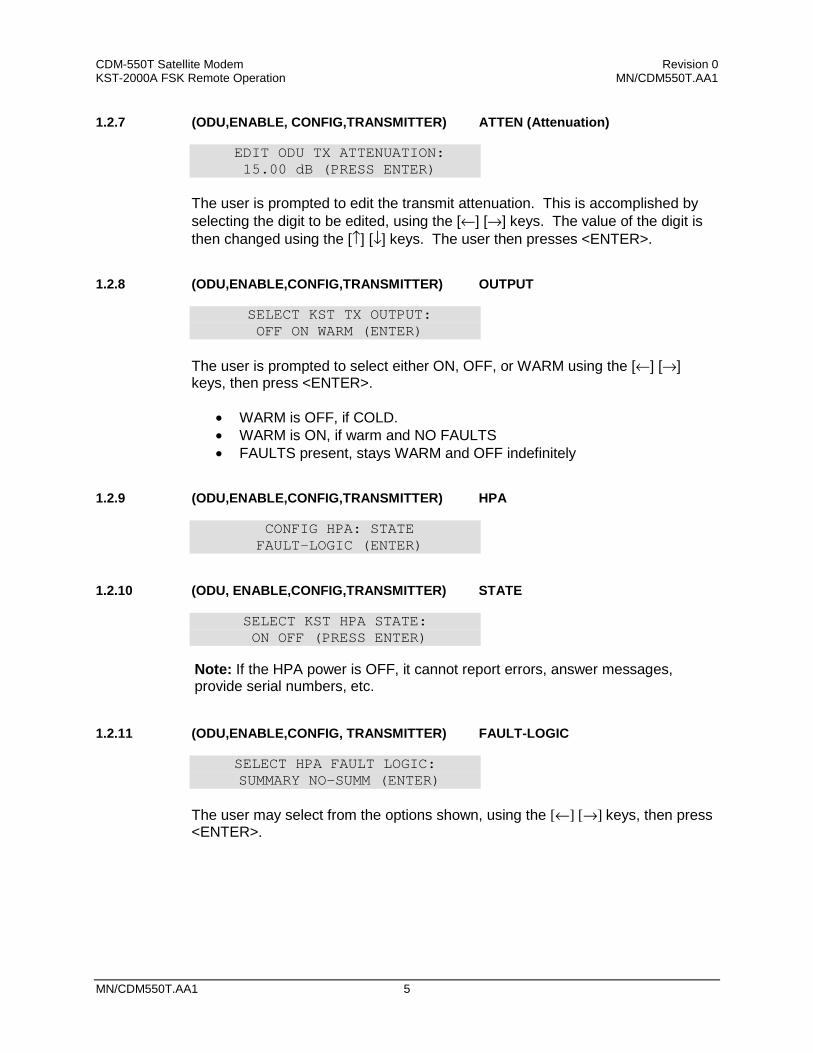
CDM-550T Satellite Modem Revision 0 KST-2000A FSK Remote Operation MN/CDM550T.AA1
MN/CDM550T.AA1 5
1.2.7 (ODU,ENABLE, CONFIG,TRANSMITTER) ATTEN (Attenuation)
EDIT ODU TX ATTENUATION: 15.00 dB (PRESS ENTER)
The user is prompted to edit the transmit attenuation. This is accomplished by selecting the digit to be edited, using the [←] [→] keys. The value of the digit is then changed using the [↑] [↓] keys. The user then presses <ENTER>.
1.2.8 (ODU,ENABLE,CONFIG,TRANSMITTER) OUTPUT
SELECT KST TX OUTPUT: OFF ON WARM (ENTER)
The user is prompted to select either ON, OFF, or WARM using the [←] [→] keys, then press <ENTER>.
• WARM is OFF, if COLD. • WARM is ON, if warm and NO FAULTS • FAULTS present, stays WARM and OFF indefinitely
1.2.9 (ODU,ENABLE,CONFIG,TRANSMITTER) HPA
CONFIG HPA: STATE FAULT-LOGIC (ENTER)
1.2.10 (ODU, ENABLE,CONFIG,TRANSMITTER) STATE
SELECT KST HPA STATE: ON OFF (PRESS ENTER)
1.2.11 (ODU,ENABLE,CONFIG, TRANSMITTER) FAULT-LOGIC
SELECT HPA FAULT LOGIC: SUMMARY NO-SUMM (ENTER)
The user may select from the options shown, using the [←] [→] keys, then press <ENTER>.
Note: If the HPA power is OFF, it cannot report errors, answer messages, provide serial numbers, etc.

CDM-550T Satellite Modem Revision 0 KST-2000A FSK Remote Operation MN/CDM550T.AA1
6 MN/CDM550T.AA1
1.2.12 (ODU,ENABLE, CONFIG) RECEIVER
ODU RX: FREQUENCY ATTEN LNA (PRESS ENTER)
This menu item is used to select which ODU Receiver parameter is to be modified. Use the [←] [→] keys, then press <ENTER>.
1.2.13 (ODU,ENABLE, CONFIG,RECEIVER) FREQUENCY
EDIT ODU RX FREQUENCY: 10950.0 MHz (PRESS ENT)
The user is prompted to edit the receive frequency. This is accomplished by selecting the digit to be edited, using the [←] [→] keys. The value of the digit is then changed using the [↑] [↓] keys. The user may then press <ENTER>.
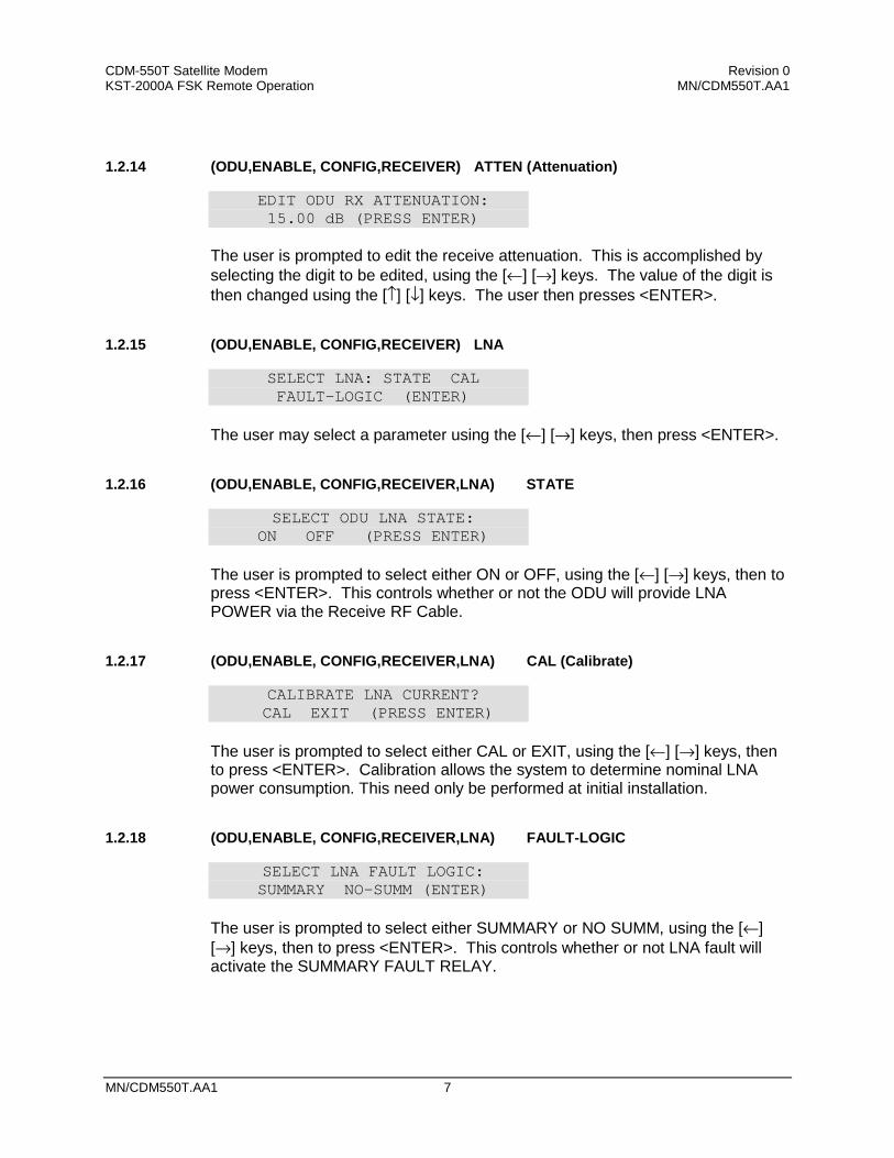
CDM-550T Satellite Modem Revision 0 KST-2000A FSK Remote Operation MN/CDM550T.AA1
MN/CDM550T.AA1 7
1.2.14 (ODU,ENABLE, CONFIG,RECEIVER) ATTEN (Attenuation)
EDIT ODU RX ATTENUATION: 15.00 dB (PRESS ENTER)
The user is prompted to edit the receive attenuation. This is accomplished by selecting the digit to be edited, using the [←] [→] keys. The value of the digit is then changed using the [↑] [↓] keys. The user then presses <ENTER>.
1.2.15 (ODU,ENABLE, CONFIG,RECEIVER) LNA
SELECT LNA: STATE CAL FAULT-LOGIC (ENTER)
The user may select a parameter using the [←] [→] keys, then press <ENTER>.
1.2.16 (ODU,ENABLE, CONFIG,RECEIVER,LNA) STATE
SELECT ODU LNA STATE: ON OFF (PRESS ENTER)
The user is prompted to select either ON or OFF, using the [←] [→] keys, then to press <ENTER>. This controls whether or not the ODU will provide LNA POWER via the Receive RF Cable.
1.2.17 (ODU,ENABLE, CONFIG,RECEIVER,LNA) CAL (Calibrate)
CALIBRATE LNA CURRENT? CAL EXIT (PRESS ENTER)
The user is prompted to select either CAL or EXIT, using the [←] [→] keys, then to press <ENTER>. Calibration allows the system to determine nominal LNA power consumption. This need only be performed at initial installation.
1.2.18 (ODU,ENABLE, CONFIG,RECEIVER,LNA) FAULT-LOGIC
SELECT LNA FAULT LOGIC: SUMMARY NO–SUMM (ENTER)
The user is prompted to select either SUMMARY or NO SUMM, using the [←] [→] keys, then to press <ENTER>. This controls whether or not LNA fault will activate the SUMMARY FAULT RELAY.

CDM-550T Satellite Modem Revision 0 KST-2000A FSK Remote Operation MN/CDM550T.AA1
8 MN/CDM550T.AA1
1.2.19 (ODU,ENABLE, CONFIG) MISCELLANEOUS
KST MISC: AGC REF-ADJUST (ENTER)
This menu item is used to select miscellaneous ODU parameters for modification. Use the [←] [→] keys, then press <ENTER>.
1.2.20 (ODU,ENABLE,CONFIG,MISCELLANEOUS) AGC (Auto Gain Control)
SEL AGC MODE: OFF ON BURST (ENTER)
The user is prompted to select either OFF, ON or BURST, using the [←] [→] keys, then to press <ENTER>.
1.2.21 (ODU,ENABLE,CONFIG,MISCELLANEOUS) REF-ADJUST
EDIT INT REF ADJUSTMENT: 028 (PRESS ENTER) The user is prompted to edit the INT 10MHz REF setting using the [↑] [↓] keys, then to press <ENTER>. The value will scroll between 000 and 255. Note: The INT REF is adjusted in the factory to be very accurate with the default setting of 028. This parameter is made available to compensate for the long-term frequency drift of the oscillator.
1.2.22 (ODU,ENABLE) INFO (Information)
INFO: TX RX HPA LNA EQUIP ASSEMBLY+SN FW (ENTER)
The operator uses this menu item to select enter 1 of 7 ‘Information Windows’. Use the [←] [→] keys, then press <ENTER>.
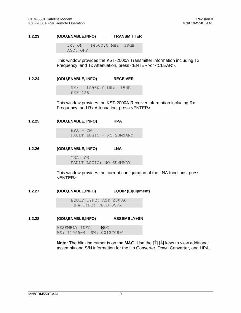
CDM-550T Satellite Modem Revision 0 KST-2000A FSK Remote Operation MN/CDM550T.AA1
MN/CDM550T.AA1 9
1.2.23 (ODU,ENABLE,INFO) TRANSMITTER
TX: ON 14500.0 MHz 19dB AGC: OFF This window provides the KST-2000A Transmitter information including Tx Frequency, and Tx Attenuation, press <ENTER>or <CLEAR>.
1.2.24 (ODU,ENABLE, INFO) RECEIVER
RX: 10950.0 MHz 15dB REF:228 This window provides the KST-2000A Receiver information including Rx Frequency, and Rx Attenuation, press <ENTER>.
1.2.25 (ODU,ENABLE, INFO) HPA
HPA = ON FAULT LOGIC = NO SUMMARY
1.2.26 (ODU,ENABLE, INFO) LNA
LNA: ON FAULT LOGIC: NO SUMMARY
This window provides the current configuration of the LNA functions, press <ENTER>.
1.2.27 (ODU,ENABLE,INFO) EQUIP (Equipment)
EQUIP-TYPE: KST-2000A HPA-TYPE: CEFD-SSPA
1.2.28 (ODU,ENABLE,INFO) ASSEMBLY+SN
ASSEMBLY INFO: M&C AS: 11565-4 SN: 001370891 Note: The blinking cursor is on the M&C. Use the [↑] [↓] keys to view additional assembly and S/N information for the Up Converter, Down Converter, and HPA.
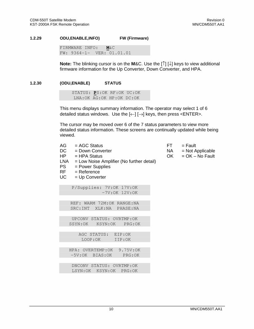
CDM-550T Satellite Modem Revision 0 KST-2000A FSK Remote Operation MN/CDM550T.AA1
10 MN/CDM550T.AA1
1.2.29 ODU,ENABLE,INFO) FW (Firmware)
FIRMWARE INFO: M&C FW: 9364-1- VER: 01.01.01 Note: The blinking cursor is on the M&C. Use the [↑] [↓] keys to view additional firmware information for the Up Converter, Down Converter, and HPA.
1.2.30 (ODU,ENABLE) STATUS
STATUS: PS:OK RF:OK UC:OK LNA:OK AG:OK HP:OK DC:OK This menu displays summary information. The operator may select 1 of 6 detailed status windows. Use the [←] [→] keys, then press <ENTER>. The cursor may be moved over 6 of the 7 status parameters to view more detailed status information. These screens are continually updated while being viewed. AG = AGC Status DC = Down Converter HP = HPA Status LNA = Low Noise Amplifier (No further detail) PS = Power Supplies RF = Reference UC = Up Converter
FT = Fault NA = Not Applicable OK = OK – No Fault
P/Supplies: 7V:OK 17V:OK -7V:OK 12V:OK
REF: WARM 72M:OK RANGE:NA SRC:INT XLK:NA PHASE:NA
UPCONV STATUS: OVRTMP:OK SSYN:OK KSYN:OK PRG:OK
AGC STATUS: EIP:OK LOOP:OK IIP:OK
HPA: OVERTEMP:OK 9.75V:OK
-5V:OK BIAS:OK PRG:OK
DNCONV STATUS: OVRTMP:OK LSYN:OK KSYN:OK PRG:OK
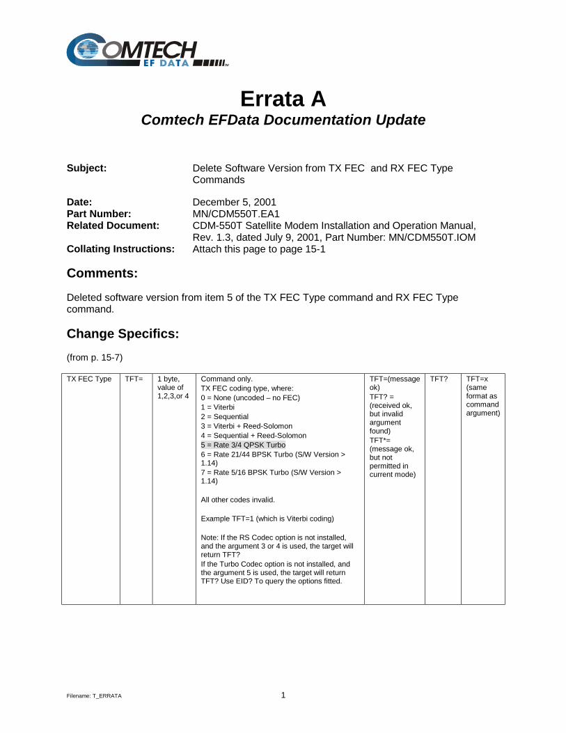
Filename: T_ERRATA 1
Errata A Comtech EFData Documentation Update
Subject: Delete Software Version from TX FEC and RX FEC Type Commands
Date: December 5, 2001 Part Number: MN/CDM550T.EA1 Related Document: CDM-550T Satellite Modem Installation and Operation Manual,
Rev. 1.3, dated July 9, 2001, Part Number: MN/CDM550T.IOM Collating Instructions: Attach this page to page 15-1 Comments:
Deleted software version from item 5 of the TX FEC Type command and RX FEC Type command.
Change Specifics: (from p. 15-7) TX FEC Type TFT= 1 byte,
value of 1,2,3,or 4
Command only. TX FEC coding type, where: 0 = None (uncoded – no FEC) 1 = Viterbi 2 = Sequential 3 = Viterbi + Reed-Solomon 4 = Sequential + Reed-Solomon 5 = Rate 3/4 QPSK Turbo 6 = Rate 21/44 BPSK Turbo (S/W Version > 1.14) 7 = Rate 5/16 BPSK Turbo (S/W Version > 1.14) All other codes invalid. Example TFT=1 (which is Viterbi coding) Note: If the RS Codec option is not installed, and the argument 3 or 4 is used, the target will return TFT? If the Turbo Codec option is not installed, and the argument 5 is used, the target will return TFT? Use EID? To query the options fitted.
TFT=(message ok) TFT? = (received ok, but invalid argument found) TFT*= (message ok, but not permitted in current mode)
TFT? TFT=x (same format as command argument)
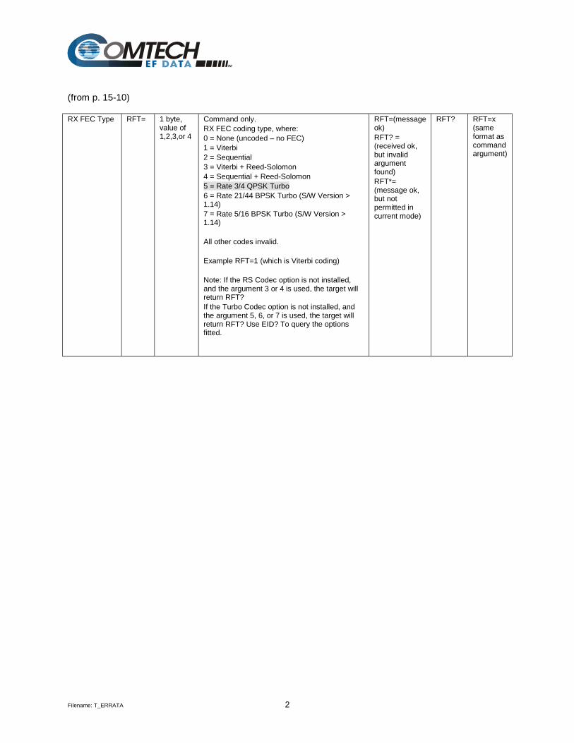
Filename: T_ERRATA 2
(from p. 15-10) RX FEC Type RFT= 1 byte,
value of 1,2,3,or 4
Command only. RX FEC coding type, where: 0 = None (uncoded – no FEC) 1 = Viterbi 2 = Sequential 3 = Viterbi + Reed-Solomon 4 = Sequential + Reed-Solomon 5 = Rate 3/4 QPSK Turbo 6 = Rate 21/44 BPSK Turbo (S/W Version > 1.14) 7 = Rate 5/16 BPSK Turbo (S/W Version > 1.14) All other codes invalid. Example RFT=1 (which is Viterbi coding) Note: If the RS Codec option is not installed, and the argument 3 or 4 is used, the target will return RFT? If the Turbo Codec option is not installed, and the argument 5, 6, or 7 is used, the target will return RFT? Use EID? To query the options fitted.
RFT=(message ok) RFT? = (received ok, but invalid argument found) RFT*= (message ok, but not permitted in current mode)
RFT? RFT=x (same format as command argument)
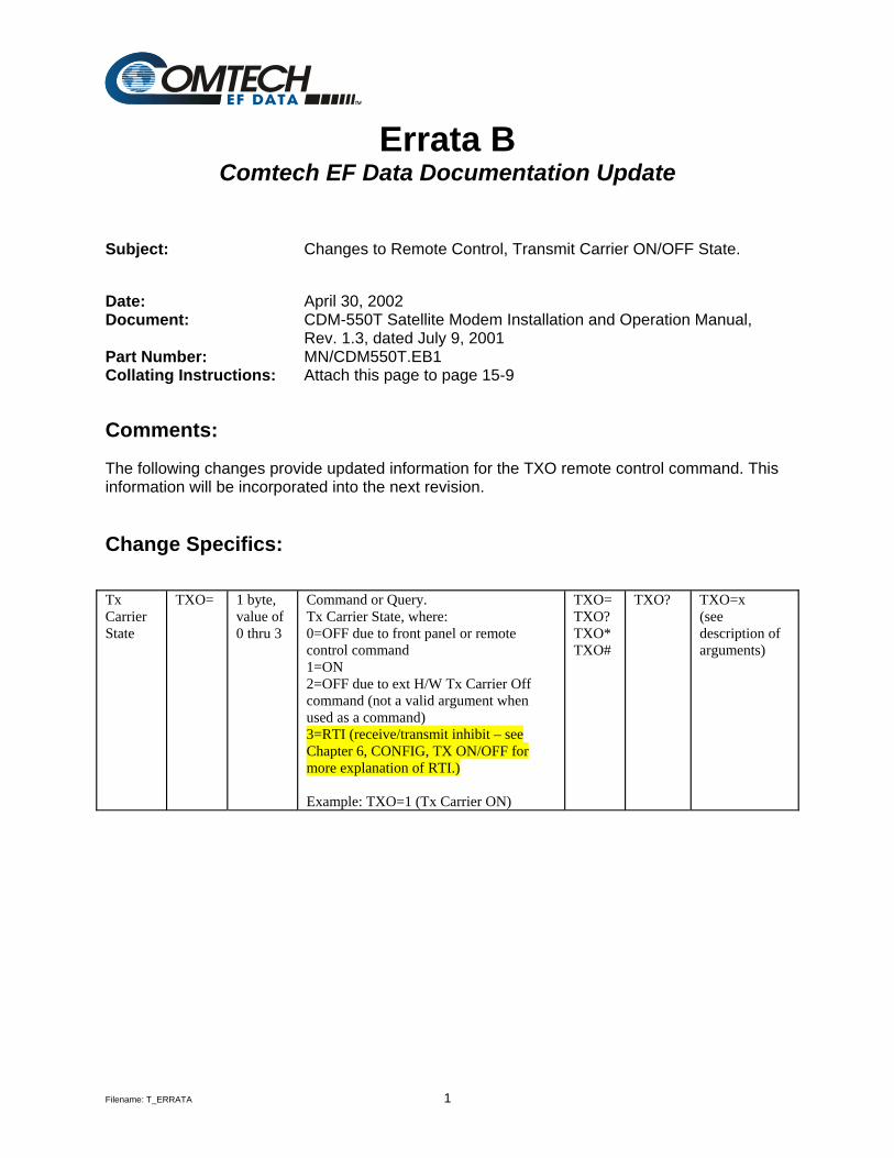
Filename: T_ERRATA 1
Errata B Comtech EF Data Documentation Update
Subject: Changes to Remote Control, Transmit Carrier ON/OFF State. Date: April 30, 2002 Document: CDM-550T Satellite Modem Installation and Operation Manual,
Rev. 1.3, dated July 9, 2001 Part Number: MN/CDM550T.EB1 Collating Instructions: Attach this page to page 15-9 Comments:
The following changes provide updated information for the TXO remote control command. This information will be incorporated into the next revision.
Change Specifics: Tx Carrier State
TXO= 1 byte, value of 0 thru 3
Command or Query. Tx Carrier State, where: 0=OFF due to front panel or remote control command 1=ON 2=OFF due to ext H/W Tx Carrier Off command (not a valid argument when used as a command) 3=RTI (receive/transmit inhibit – see Chapter 6, CONFIG, TX ON/OFF for more explanation of RTI.) Example: TXO=1 (Tx Carrier ON)
TXO= TXO? TXO* TXO#
TXO? TXO=x (see description of arguments)