Embed Size (px)
Citation preview

InstructIon ManualBulletin 20 95 05revision 0302 / 2012
coupling capacitorVoltage transformers
couplingcapacitors
ccVtcc


ContentsPage
Introduction 3Construction and Types 4 • Capacitor Voltage Transformers 4 • Coupling Capacitors 4 • Heaters 4Inspection 4 • Shielding Ring 4Storage & Transportation 4Installation 4 • Erection 4 • Capacitor Assembly Instructions 4Connections 6Commissioning and Routine Maintenance 6 • Electrical Tests 7Capacitance Bridge Testing 7Capacitance and Dissipation Factor Measurements 7Precautions for High Voltage Testing 8Connection of a Non-Linear (Magnetic) Burden 9CVT Principle of Operation 9 • Main Components 9 • Auxiliary Components 9For after sales assistance 22
IllustrationPage
Fig. 1 Sectioned Perspective View of a Typical Capacitor Voltage Transformer 5Fig. 2 Capacitor units assembly and connection 5Fig. 3 Low Voltage Terminal Box for CVT 6Fig. 4 Capacitance and Dissipation Factor Temperature Correction Curves for Paper-Film/PXE Capacitor 8Fig. 5 Schematic Diagram of a typical CVT 10Fig. 6 Capacitor Voltage Transformer with One Capacitor Section (Test 1 to 2) 11Fig. 7 Capacitor Voltage Transformer with Two Capacitor Sections (Test 1 to 3) 12Fig. 8 Capacitor Voltage Transformer with Three Capacitor Sections (Test 1 to 4) 13Fig. 9 Capacitor Voltage Transformer with Four Capacitor Sections (Test 1 to 5) 15
TablesPage
Table I Troubleshooting 18Table II Types: TCVT , TECF, TECP, TEVF, TEMF, TEVP, TERP, TEMP & TETP 19Table III Types: TCVT , TEICF, TEIRF and TEIMF 20Table IV Types: TEHCF, TEHCP, TEHMF, and TEHMP 20Table V Electrical Performance 21
Instruction Manual for Coupling Capacitor Voltage Transformers & Coupling Capacitors 3
Introduction
Trench Limited manufactures a comprehensive range of capacitor voltage transformers (CVT’s) and coupling capacitors (CC’s). All basebox types utilize the same design principles and manufacturing techniques, the information detailed in this manual is applicable in general, except where noted.
The circuit diagrams, drawings and other data in this manual may vary in minor details, from the equipment supplied. In all cases the diagrams supplied by the factory and identified with the equipment will be correct in all details.
The contents of this manual are designed to cover most situations, which may occur in practice. If any additional information is required, please contact Trench Limited.

Construction and TypesFig. 1 shows detailed cross sectional views of a typical capacitor voltage transformer. All Trench Instrument Transformer Products contain oil, which has less than 2-PPM PCB considered as non-detectable amount.
Capacitor Voltage TransformersTypes TCVT, TEVF, TEMF, TEVP, TEMP, TETP, TERP, TEIRF, TEIMF, TEHMF and TEHMP are capacitor voltage transformers (CVT’s) for use with PLC coupling schemes, protective relaying and metering applications. They comprise of an assembly of one or more capacitor units mounted on oil filled aluminum basebox or electromagnetic unit (EMU), which contains the intermediate transformer, series reactor and auxiliary components.
A low voltage terminal box houses the secondary terminals and auxiliary components.
Coupling CapacitorsTypes TECF, TECP, TEICF, TEHCF and TEHCP are coupling capacitors (CC’s) for use in power line carrier (PLC) coupling schemes. They consist of an assembly of one or more capacitor units of a flat base design with no carrier accessories or mounted on an air-filled aluminum basebox complete with carrier accessories.
The film/paper/PXE fluid insulation system represents a premium system of a low dielectric loss design and outstanding stability performance.
HeatersNote that Trench oil filled EMU’s do not require heaters. In the low voltage terminal box, heaters may be installed to prevent condensation during long storage periods in very humid environments. Power rating of heaters could be up to 15 watts and dual voltages 120/240V or 240/480V. Once the CVT is in service it is not recommended to keep the heater on especially when ambient temperature exceeds 40°C.
InspectionAll shipments should be inspected upon arrival for chipped or damaged porcelains, metallic parts and oil leaks. The LV terminal box should be opened and examined for loose components or broken wiring. If transit damage has been found, file a claim with the Transit Company and notify Trench Limited immediately.
Shielding RingWhen a shielding ring is supplied, refer to the outline drawing regarding the way the shielding ring should be mounted on the unit. Check the shielding ring for any scratches or sharp points, which may have been caused during transit and file smooth before installation.
Storage & TransportationUnits may be safely stored upright only on level ground, outdoors for a reasonable period of time. Multiple capacitor units are shipped with the upper capacitorunits removed and bolted to the skid alongside the basebox. The top ends of the capacitors exposed by the removal of the upper units are protected from the weather by temporary plastic bag covers, which should be examined when equipment is placed in storage, and adjusted if found to be damaged or loosened.
Units must be only transported in the upright position preferably with their original packaging.
InstallationErectionCC’s or CVT’s with more than one capacitor unit are shipped with the units disassembled. They are crated in sets with all components required to assemble one CVT unit in one crate. Capacitor units must not be interchanged with capacitors from different CVT’s.
Assembling of CVT’s can be performed with assistance of a lifting crane. The use of rope slings with a choker-type hitch arranged to bear on the upper metal flange is an effective way of lifting the capacitor units.
Assembling can be carried out as follows:Mount the basebox and bottom capacitor assembly on its pedestal and prepared foundation and assemble subsequent capacitor units on top in accordance with the instructions detailed below.
Capacitor Assembling InstructionsElectrical connection between capacitor sections is done by direct mounting of the upper capacitor section onto the lower capacitor section. The capacitors are secured by axial bolts around the capacitor flange that must be tightened to 20 ft. lb. (27 Nm). For easy reference, the individual nameplates should be aligned with each other during assembling. Fig.2 shows details of the assembly and connection procedure.
For high seismic areas, the use of damping pads may be required. Please refer to the contract drawings supplied with the equipment.
Caution:It is essential that the capacitor unit serial numbers shown on the main nameplate of the CVT match the actual serial numbers of the capacitor units installed on the device.
Note:Accuracy performance may be severely affected if capacitor units are interchanged between CVT’s.
Instruction Manual for Coupling Capacitor Voltage Transformers & Coupling Capacitors4

Instruction Manual for Coupling Capacitor Voltage Transformers & Coupling Capacitors 5
Fig. 1 Sectioned Perspective View of a Typical Capacitor Voltage Transformer
Fig. 2 Capacitor unit’s assembly and connection
Connections
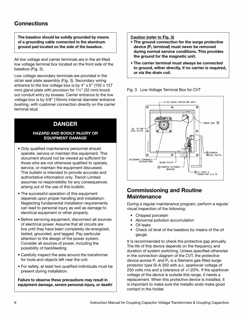
All low voltage and carrier terminals are in the air-filled low voltage terminal box located on the front side of the basebox (Fig. 3).
Low voltage secondary terminals are provided in the oil/air seal plate assembly (Fig. 3). Secondary wiring entrance to the low voltage box is by 4” x 5” (102 x 127 mm) gland plate with provision for 1¼” (32 mm) knock out conduit entry by bosses. Carrier entrance to the low voltage box is by 5/8” (16mm) internal diameter entrance bushing, with customer connection directly on the carrier terminal stud.
Fig. 3 Low Voltage Terminal Box for CVT
Commissioning and Routine MaintenanceDuring a regular maintenance program, perform a regular visual inspection of the following:
• Chipped porcelain • Abnormal pollution accumulation • Oil leaks • Check oil level of the basebox by means of the oil
gauge.
It is recommended to check the protective gap annually. The life of this device depends on the frequency and duration of system switching. Unless specified otherwise in the connection diagram of the CVT, the protective device across P1 and P2 is a Siemens gas-filled surge protector type SI-A 350 with a.c. sparkover voltage of 250 volts rms and a tolerance of +/-20%. If the sparkover voltage of the device is outside this range, it needs a replacement. When this protective device is installed, it is important to make sure the metallic ends make good contact in the holder.
Caution (refer to Fig. 3)• The ground connection for the surge protective
device (P2 terminal) must never be removed during normal service conditions. This provides the ground for the magnetic unit.
• The carrier terminal must always be connected to ground, either directly, if no carrier is required, or via the drain coil.
Instruction Manual for Coupling Capacitor Voltage Transformers & Coupling Capacitors6
The basebox should be solidly grounded by means of a grounding cable connected to the aluminum ground pad located on the side of the basebox.
• Only qualified maintenance personnel should operate, service or maintain this equipment. This document should not be viewed as sufficient for those who are not otherwise qualified to operate, service, or maintain the equipment discussed. This bulletin is intended to provide accurate and authoritative information only. Trench Limited assumes no responsibility for any consequences arising out of the use of this bulletin.
• The successful operation of this equipment depends upon proper handling and installation. Neglecting fundamental installation requirements can lead to personal injury as well as damage to electrical equipment or other property.
• Before servicing equipment, disconnect all sources of electrical power. Assume that all circuits are live until they have been completely de-energized, tested, grounded, and tagged. Pay particular attention to the design of the power system. Consider all sources of power, including the possibility of backfeeding.
• Carefully inspect the area around the transformer for tools and objects left near the unit.
• For safety, at least two qualified individuals must be present during installation.
Failure to observe these precautions may result in equipment damage, severe personal injury, or death!
DANGER
HAZARD AND BODILY INJURY OREQUIPMENT DAMAGE

Instruction Manual for Coupling Capacitor Voltage Transformers & Coupling Capacitors 7
If a preventive maintenance program calls for regular electrical tests, the following procedures may serve as a guide for tests on a routine basis as governed by your usual practice. If it is the practice of your utility to conduct a check at the time of commissioning, then these same procedures may be followed at this time.
If the CVT is utilized for PLC only, the potential ground switch must remain in the open position.
Electrical TestsSee precautions for HV testing on page 8 before doing the tests.
Measure capacitance and dissipation factor of each capacitor unit.
It is important to use equipment with a capacitance measurement error of less than 0.5% in order to detect a capacitor element failure. This can be achieved by the use of Low Voltage Capacitance Bridge. All measurements taken should be corrected to 20°C using Fig. 4.
As there will always be differences between the calibrations of various capacitance measuring equipment, the initial capacitance readings on installation should be recorded and used as a basis for comparison with subsequent measurements made with the same test equipment.
• Measure the transformation ratio of the unit (CVT’s only). The purpose of this test is to verify the continuity of the CVT circuit only. The use of Doble Test equipment as a power supply to the HV terminal and measurement of secondary voltage is a convenient method of doing this measurement.
Capacitance Bridge TestingIt is possible, but not likely, for a damaged capacitor element to recover after de-energisation and the unit capacitance appear to be normal when measured at a low voltage, using a low voltage capacitance bridge. Factory measurements are made at normal operating voltage.
Measure upper units by attaching the test leads directly to the joining bolts.
For CVT’s, the presence of the intermediate transformer connected to the tapping point on the bottom unit requires special consideration. Refer to the connection diagram and low voltage terminal box and follow the procedure described below:
• Close voltage tap ground switch and measure “C1”, (HV terminal to basebox with ground switch closed). Compare to value marked on main nameplate or measurements taken in previous tests.
• With ground switch still closed, measure “C2”. Remove ground connection at “CAR” terminal and measure between this terminal and basebox. Compare to C2 value marked on main nameplate or previous measurements.
• Measure “C total”, from HV terminal to “CAR” terminal with ground switch open and grounding links removed from “P2” and “CAR” terminals. Depending on the type of bridge used, there may be difficulties in obtaining a balance for DF as leakage currents through the insulation of the transformer windings will cause apparent DF readings below the true value or even to be negative, although capacitance value obtained will be correct. A change of measurement “C” total from one routine test to another would be an indicator that additional investigation is required.
Note that, on the bottom capacitor unit, the lower end plate is isolated from the capacitor electrodes and cannot be used as a connection point.
Capacitance and Dissipation Factor MeasurementsThe procedures outlined below are operating instructions for the use with Doble M4000 equipment.
The power factor reading from the capacitance and dissipation factor (DF) test corresponds to the DF shown on the nameplate of each capacitor unit. The DF reading depends upon good solid test connections being established and care must therefore be taken to obtain valid test results. The capacitance data obtained at commissioning stage may differ from the nameplate values and therefore the capacitance measurement done at commissioning should be used as a reference for future comparison. A capacitor element failure will result in an increase in the total capacitance in proportion to the original number of elements and those remaining in operating condition. Generally, an increase of 1% in capacitance from the reference data obtained during commissioning would be significant. The capacitance of the capacitor unit should be preferably measured with the same equipment and compared to the commissioning data to ensure good working condition of the capacitor assembly.
Capacitance and dissipation factor test can be carried out on all ratings of Trench Limited coupling capacitors and capacitor voltage transformers.
For coupling capacitors, the carrier bushing is accessible and tests can be done by energizing either top or bottom end of the capacitor as required.
For capacitor voltage transformers, the HV terminal must be disconnected from the HV bus for accurate measurements.

If solidly bolted bus connections are to be used, it is recommended that suitable insulating supports be installed to isolate the CVT for test purposes. Shorting links normally used across these insulating supports may then be easily removed during tests and replaced afterwards.
The test methods for assemblies which have 1, 2, 3 or4 capacitor units, are detailed below and from page 11to 17.
• Remove carrier ground connection for the duration of the capacitance and dissipation factor test
• Ground the basebox solidly to the test set
• Close the voltage tap ground switch
NOTE: It is not unusual for dissipation factor (DF) measurements made at 10kV or below to exceed factory values, which are measured at operating voltage. If DF exceeds 0.4 %, consult Trench Limited.
Example for use of Fig. 4
1. Make measurement at field temperature. Example: Temperature = -10°C Capacitance = 10050 pF Dissipation Factor = 0.065%
2. Find our factory values from test report. Example: Capacitance = 10 000 pF Dissipation Factor = 0.055%
3. Calculate predicted values at field temperature. Example: Capacitance at -10°C = 100.25% of factory value = 10025 pF
4. Dissipation Factor at -10°C = 113% of factory value = 0.062%
Compare values from 1 and 4.
Fig. 4 Capacitance and Dissipation Factor Temperature Correction Curves for Paper-Film/PXE Capacitor
Note: Measurement is done at normal operating voltage. Significant error on dissipation factor may result if measurement performed at low voltage (1-10kV).
Precautions for High Voltage TestingIf HV testing methods are employed on complete CVT’s, the following precautions should be taken:
• Do not energize the HV terminal above the normal rated line-to-ground voltage of the unit. The terminals “P2” and “P1” are connected to the high voltage side of the electromagnetic unit of the CVT which is subsequently connected to the tap capacitance “C2”. If “P2” is not properly grounded and the CVT is energized with the potential ground switch in open position, a voltage of 5 to 11 kV will appear at “P2” and “P1” terminals (Refer to Fig. 5).
• The normal operating voltage of the tapping point is approximately 5 kV (TEVF), 11 kV (TEMF, TEMP and TEHMF), 5 to 11 kV (TCVT). It is recommended that capacitance measurements be taken at voltages below the normal rated voltage of the unit, so that the voltage appearing on “P1” and “P2” terminals during the measurement will be proportionately reduced.
• Extreme care must be taken to ensure that connections to the “CAR” terminal are completely away from the “P1” and “P2” terminals, because of the high voltage which will appear at these terminals.
• Qualified personnel only, who fully understand the circuit involved, should make measurements.
• Maximum test voltage to “P1” and “P2” and “CAR” terminals with respect to grounds should not exceed 2 kV.
Instruction Manual for Coupling Capacitor Voltage Transformers & Coupling Capacitors8
• IMPORTANT: Replace carrier connection immediately after test, before energizing.
During storage, ensure that all capacitor insulator assemblies are shorted.
Failure to observe these precautions can result in personal injury or product damage.
WARNINGHAZARD OF ELECTRIC SHOCK.

Instruction Manual for Coupling Capacitor Voltage Transformers & Coupling Capacitors 9
Connection of a Non-Linear (Magnetic) BurdenCaution must be used when using non-linear (or magnetic) burdens with CVT’s. Non-linear burdens connected to the CVT may cause harmonics in the output voltage and current within the electromagnetic components of the CVT, which, in turn, may cause variation in ratio and phase angle errors as well as increasing the voltage across the protective gaps. During momentary overvoltage conditions, the effects of a non-linear burden may cause P1 - P2 flashover and, thereby, interfere with the operation of the relaying systems.
Most relays, synchroscopes, voltmeters and other generally used instruments are essentially linear burdens up to twice the normal voltage. Burdens with closed magnetic circuits such as auxiliary potential transformers may not have linear characteristics over the entire voltage range.
If such devices are used in the secondary circuits, these should be selected so that the iron core is operating at not more than one-half the flux density required to reach the knee of the magnetization curve. For example, it is desirable to use a 230-230 volt auxiliary potential transformer in the 115-volt circuit instead of one having a 115-115 volt rating. The same precaution should be taken for relay coils.
CVT Principle of OperationMain ComponentsThe main components are the capacitor divider, the intermediate step-down transformer and the series reactor, as shown in Fig. 5.
The step-down transformer and series reactors are connected to the intermediate voltage tap between C1 & C2. The series reactor is manufactured so its impedance cancels the impedance of the capacitor; therefore, the full intermediate voltage is delivered to the terminals of the step-down transformer, in phase with the primary line voltage. The series reactor and primary winding of the step-down transformer are manufactured with taps to enable ratio and phase angle adjustment. These are factory preset and do not require alteration after delivery unless a capacitor unit is changed.
Auxiliary ComponentsAll items referred to are identified on the connection diagram.
The choke coil assembly prevents the grounding of the carrier signal when the voltage tap ground switch is closed.
The harmonic suppression filter prevents sustained ferroresonance oscillations. It consists of a resistor in series with a saturable reactor and a parallel resistor. The reactor is designed to saturate above the highest over-voltage rating to form a loading circuit, which will dampen sub-harmonic ferroresonant oscillations.
The protective gap (item 4 Fig. 5) is a voltage sensitive device wired in series with a loading resistor on a secondary winding of the series reactor. The protective gap is normally open circuit, but goes in short circuit mode when the intermediate voltage exceeds the overvoltage factor of the CVT, or when the secondary current causes the thermal burden rating (shown in Table V) to be exceeded. This has the effect of de-tuning the CVT and limiting the secondary current available during overvoltage and external short circuit conditions. The protective gap also serves to further limit ferroresonance oscillations. If the fault condition persists for more than about thirty seconds, the protective gap will not reset from the short circuit mode and must be replaced. Its location inside the low voltage terminal box facilitates replacement.
The drain coil, gap and carrier ground switch are supplied if the CVT is to function as a coupling capacitor for power line carrier.
CAUTION on operation of potential ground switch:
The potential ground switch position (see Fig. 5, item 7) is provided for maintenance purposes only. It is not meant to be closed on permanent basis, due to increased stress of C1 capacitor elements. Closing the potential ground switch for more than 8 hours is not recommended.

Fig. 5 Schematic Diagram of a typical CVT
Instruction Manual for Coupling Capacitor Voltage Transformers & Coupling Capacitors10
Note: connection between internal terminals L1…L8 and A, D…O are made at the factory as required for each unit.
UNIVERSAL BOX LOW PROFILE BOXBas
e b
ox
typ
e
Series Reactors Intermediate Voltage Transformer Harmonic Suppression Filter Sealed Protective Gap
Secondary Terminal Board Faraday Field Potential Ground Switch Choke Coil & Gap Assembly
Drain Coil, Gap & Carrier Ground Switch Assembly
Wit
hout
car
rier
acc
esso
ries
Wit
h ca
rrie
r ac
cess
ori
es
Legend: 1
2
3
4
5
6
7
8
9

Instruction Manual for Coupling Capacitor Voltage Transformers & Coupling Capacitors 11
Fig. 6 Capacitor Voltage Transformer with One Capacitor Section (Test 1 to 2)
• Test 1 - one capacitor section
Test Procedures
Measure:Test Voltage:Circ. Desc.:
HV Lead:LV Lead:
F:S1 Switch:S2 Switch:
C1
10kVGST-GROUNDA-GroundedGroundedGrounded
Note:S1: Carrier ground switchS2: Voltage tap ground switchL1: Drain coilL2: Choke coil
• Test 2 - one capacitor section
Test Procedures
Measure:Test Voltage:Circ. Desc.:
HV Lead:LV Lead:
F:
S1 Switch:S2 Switch:
C2
2kVGND-RBF-Disconnected(carrier lead)GroundedGrounded
Note:S1: Carrier ground switchS2: Voltage tap ground switchL1: Drain coilL2: Choke coil

Instruction Manual for Coupling Capacitor Voltage Transformers & Coupling Capacitors12
Fig. 7 Capacitor Voltage Transformer with Two Capacitor Sections (Test 1 to 3)
• Test 1 - two capacitor sections
Test Procedures
Measure:Test Voltage:Circ. Desc.:
HV Lead:LV Lead:
F:S1 Switch:S2 Switch:
C1-1
10kVGAR-RBAGroundedGroundedGrounded
Note:S1: Carrier ground switchS2: Voltage tap ground switchL1: Drain coilL2: Choke coil
• Test 2 - two capacitor sections
Test Procedures
Measure:Test Voltage:Circ. Desc.:
HV Lead:LV Lead:
F:S1 Switch:S2 Switch:
C1-2
10kVUST-RBAGroundedGroundedGrounded
Note:S1: Carrier ground switchS2: Voltage tap ground switchL1: Drain coilL2: Choke coil

Instruction Manual for Coupling Capacitor Voltage Transformers & Coupling Capacitors 13
• Test 3 - two capacitor sections
Test Procedures
Measure:Test Voltage:Circ. Desc.:
HV Lead:LV Lead:
F:
S1 Switch:S2 Switch:
C2
2kVGND-RBF-Disconnected(carrier lead)GroundedGrounded
Note:S1: Carrier ground switchS2: Voltage tap ground switchL1: Drain coilL2: Choke coil
Fig. 8 Capacitor Voltage Transformer with Three Capacitor Sections (Test 1 to 4)
• Test 1 - three capacitor sections
Test Procedures
Measure:Test Voltage:Circ. Desc.:
HV Lead:LV Lead:
A, F:S1 Switch:S2 Switch:
C1-1
10kVGAR-RCBGroundedGroundedGrounded
Note:S1: Carrier ground switchS2: Voltage tap ground switchL1: Drain coilL2: Choke coil

Instruction Manual for Coupling Capacitor Voltage Transformers & Coupling Capacitors14
• Test 2 - three capacitor sections
Test Procedures
Measure:Test Voltage:Circ. Desc.:
HV Lead:LV Lead:
A, F:S1 Switch:S2 Switch:
C1-2
10kVUST-RBCGroundedGroundedGrounded
Note:S1: Carrier ground switchS2: Voltage tap ground switchL1: Drain coilL2: Choke coil
• Test 3 - three capacitor sections
Test Procedures
Measure:Test Voltage:Circ. Desc.:
HV Lead:LV Lead:
A, F:S1 Switch:S2 Switch:
C1-3
10kVGAR-RBCGroundedGroundedGrounded
Note:S1: Carrier ground switchS2: Voltage tap ground switchL1: Drain coilL2: Choke coil

Instruction Manual for Coupling Capacitor Voltage Transformers & Coupling Capacitors 15
• Test 4 - three capacitor sections
Test Procedures
Measure:Test Voltage:Circ. Desc.:
HV Lead:LV Lead:
A:F:
S1 Switch:S2 Switch:
C2
2kVGND-RBF-Grounded Disconnected(carrier lead)GroundedGrounded
Note:S1: Carrier ground switchS2: Voltage tap ground switchL1: Drain coilL2: Choke coil
Fig. 9 Capacitor Voltage Transformer with Four Capacitor Sections (Test 1 to 5)
• Test 1 - four capacitor sections
Test Procedures
Measure:Test Voltage:Circ. Desc.:
HV Lead:LV Lead:
A, F:S1 Switch:S2 Switch:
C1-1
10kVGAR-RDCGroundedGroundedGrounded
Note:S1: Carrier ground switchS2: Voltage tap ground switchL1: Drain coilL2: Choke coil

Instruction Manual for Coupling Capacitor Voltage Transformers & Coupling Capacitors16
• Test 2 - four capacitor sections
Test Procedures
Measure:Test Voltage:Circ. Desc.:
HV Lead:LV Lead:
A, F:S1 Switch:S2 Switch:
C1-2
10kVUST-RCDGroundedGroundedGrounded
Note:S1: Carrier ground switchS2: Voltage tap ground switchL1: Drain coilL2: Choke coil
• Test 3 - four capacitor sections
Test Procedures
Measure:Test Voltage:Circ. Desc.:
HV Lead:LV Lead:
A, F:S1 Switch:S2 Switch:
C1-3
10kVUST-RBCGroundedGroundedGrounded
Note:S1: Carrier ground switchS2: Voltage tap ground switchL1: Drain coilL2: Choke coil

Instruction Manual for Coupling Capacitor Voltage Transformers & Coupling Capacitors 17
• Test 4 - four capacitor sections
Test Procedures
Measure:Test Voltage:Circ. Desc.:
HV Lead:LV Lead:
A, F:S1 Switch:S2 Switch:
C1-4
10kVGAR-RBCGrounded GroundedGrounded
Note:S1: Carrier ground switchS2: Voltage tap ground switchL1: Drain coilL2: Choke coil
• Test 5 - four capacitor sections
Test Procedures
Measure:Test Voltage:Circ. Desc.:
HV Lead:LV Lead:
A:F:
S1 Switch:S2 Switch:
C2
2kVGND-RBF-GroundedDisconnected(carrier lead)GroundedGrounded
Note:S1: Carrier ground switchS2: Voltage tap ground switchL1: Drain coilL2: Choke coil

18
Table I TroubleshootingThe following is a list of possible problems and their solutions. If difficulty is encountered at any stage,please contact Trench Limited.
Pro
ble
m
Po
ssib
le C
ause
P
roce
dur
es
Zer
o S
econ
dar
y O
utp
ut
1.1
Volt
tap
gro
und
sw
itch
clos
ed
Op
en v
olt
tap
gro
und
sw
itch
(up
pos
ition
)
1.
4 N
o co
nnec
tion
bet
wee
n un
its
Con
firm
as
per
tes
t 1.
3.2
and
1.3
.3.
2.
2 Fa
ilure
of a
C2
cap
acito
r el
emen
t C
heck
C2
valu
e as
per
tes
t 1.
3.2.
2.
3 E
xtre
me
load
on
seco
ndar
y R
emov
e ex
tern
al w
iring
to
sub
stat
ion
and
re-
chec
k se
cond
ary
outp
ut a
t te
rmin
als.
1.
5 B
roke
n co
nnec
tion
insi
de
cap
acito
r un
it A
s p
er t
est
1.3.
2 an
d 1
.3.3
. If n
o co
ntin
uity
, con
firm
tha
t co
nnec
tions
bet
wee
n ca
pac
itor
un
its a
re m
ade.
If s
till n
o co
ntin
uity
, cha
nge
cap
acito
r un
it.
1.
2 S
hort
circ
uit
on s
econ
dar
y co
nnec
tions
R
emov
e ex
tern
al w
iring
and
mea
sure
out
put
vol
tage
at
term
inal
s. If
the
re is
stil
l no
volta
ge,
th
en p
roce
ed a
s fo
llow
s:
1. M
egge
r X
and
Y w
ind
ings
to
tank
sho
uld
rea
d 5
0 m
eg o
hms
or m
ore.
2.
Rem
ove
P2
grou
nd li
nk.
3.
Op
en g
roun
d s
witc
h.
4. M
egge
r P
2 to
tan
k sh
ould
rea
d 5
0 m
eg o
hms
or m
ore.
1.
3 O
pen
circ
uit
on in
term
edia
te t
rans
form
er
Rem
ove
P2
conn
ectio
n.
C
lose
vol
t ta
p g
roun
d s
witc
h.
1. M
easu
re r
esis
tanc
e fr
om P
2 co
nnec
tion
to t
ank,
sho
uld
rea
d le
ss t
han
1000
ohm
s.
R
emov
e ca
rrie
r gr
ound
con
nect
ion
and
clo
se v
olt
tap
gro
und
sw
itch.
2.
Mea
sure
cap
acita
nce
bet
wee
n C
AR
con
nect
ion
and
bas
ebox
. Thi
s gi
ves
C2
valu
e.
3. M
easu
re c
apac
itanc
e fr
om t
op o
f cap
acito
r to
bas
ebox
. Thi
s gi
ves
C1
valu
e. E
ither
of a
bov
e te
sts
will
con
firm
inte
grity
of t
ap le
ad fr
om lo
wer
cap
acito
r un
it.
4. M
easu
re P
1 -
P2,
sho
uld
rea
d le
ss t
han
75 o
hms
C
AU
TIO
N: B
EFO
RE
PE
RFO
RM
ING
AN
Y T
ES
TS E
NS
UR
E T
HAT
UN
IT H
AS
BE
EN
CO
MP
LETE
LY D
E-E
NE
RG
IZE
Low
Sec
ond
ary
Out
put
2.
1 P
oor
seco
ndar
y co
nnec
tion
Che
ck a
ll co
nnec
tions
.
Hig
h S
econ
dar
y O
utp
ut
3 Fa
ilure
of o
ne o
r m
ore
C1
cap
acito
r el
emen
ts
Rem
ove
unit
from
ser
vice
imm
edia
tely
for
eval
uatio
n. C
heck
C1
per
1.3
.3
Rep
lace
cap
acito
r un
it if
cap
acita
nce
is m
ore
than
1%
hig
h.
Fluc
tuat
ing
Sec
ond
ary
4 Lo
ose
inte
rmed
iate
or
seco
ndar
y co
nnec
tions
C
heck
all
conn
ectio
ns.
Out
put
Hig
h D
issi
pat
ion
Fact
or
5 O
il co
ntam
inat
ion
due
to
cap
acito
r el
emen
t R
emov
e un
it fr
om s
ervi
ce im
med
iate
ly. R
epla
ce c
apac
itor
unit.
in C
apac
itor
Uni
t(s)
arci
ng/f
ailu
re
Hig
h C
apac
itanc
e Va
lues
6
Cap
acito
r el
emen
t fa
ilure
A
s ab
ove
(5)
Low
Cap
acita
nce
Valu
es
7 P
ossi
ble
mea
sure
men
t er
ror
Che
ck m
easu
rem
ent
equi
pm
ent.
Wav
efor
m D
isto
rtio
n 8.
1 M
alfu
nctio
n of
har
mon
ic s
upp
ress
ion
filte
r C
heck
har
mon
ic s
upp
ress
ion
filte
r w
iring
and
com
pon
ents
, rep
lace
as
nece
ssar
y.
Low
Oil
Leve
l in
Bas
ebox
11
.1
Ext
rem
ely
low
am
bie
nt t
emp
erat
ure
In n
o ca
se s
houl
d o
il le
vel b
e m
ore
than
10
mm
(3/8
”) b
elow
mar
k. T
op u
p if
nec
essa
ry.
Hig
h O
il Le
vel i
n B
aseb
ox
10.1
E
xtre
mel
y hi
gh a
mb
ient
tem
per
atur
e In
no
case
sho
uld
oil
be
mor
e th
an 1
0 m
m (3
/8”)
ab
ove
mar
k.
Sig
n of
Oil
on P
orce
lain
s 12
.1
Oil
leak
of e
xpan
sion
cha
mb
er
Rep
lace
exp
ansi
on c
ham
ber
.
Low
Sec
ond
ary
Out
put
9.
1 P
1 -
P2
surg
e p
rote
ctor
sho
rted
R
epla
ce s
urge
pro
tect
or.
and
Pha
se A
ngle
Err
or
8.
2 U
se o
f non
line
ar (s
atur
able
) bur
den
S
ee fu
rthe
r se
ctio
n “C
onne
ctio
n of
sat
urab
le (n
on-l
inea
r) b
urd
en”.
11
.2
Bas
ebox
leak
ing
oil
Che
ck fo
r le
aks
arou
nd t
ank
and
rep
ort
to fa
ctor
y if
nece
ssar
y.
10
.2
Oil
leak
in lo
wer
cap
acito
r un
it ta
p o
r ca
rrie
r C
heck
exp
ansi
on c
ham
ber
on
top
of l
ower
cap
acito
r un
it. C
onsu
lt fa
ctor
y im
med
iate
ly.
bus
hing
12
.2
Cap
acito
r fa
ilure
cau
sing
exp
ansi
on c
ham
ber
In
spec
t ex
pan
sion
cha
mb
er. I
f pun
ctur
ed, r
emov
e un
it fr
om s
ervi
ce im
med
iate
ly.
to p
unct
ure
Con
sult
fact
ory.
9.
2 Fa
ulty
har
mon
ic s
upp
ress
ion
filte
r A
s ab
ove
(8.1
).
Instruction Manual for Coupling Capacitor Voltage Transformers & Coupling Capacitors

Instruction Manual for Coupling Capacitor Voltage Transformers & Coupling Capacitors 19
Table II Types: TCVT, TECF, TECP, TEVF, TEMF, TEVP, TERP, TEMP & TETP
Dimensions TCVT, TECF, TEVF & TEMF (with Low Profile Base Tank)
Dimensions TCVT, TECP, TEVP, TERP, TETP (with Low Profile Base Tank) & TEMP (with Universal Base Tank)
1. 345 kV, 1300 kV BIL designs available without shielding rings * Not applicable to TECF, TECP
PARAMETER UNIT 72.5 123 145 170 245 300 362 420 550
Number of capacitor units 1 1 1 1 1 2 2 3 2
Number of capacitor units 1 1 1 1 1 2 2 3 2
Shielding ring No No No No Yes No Yes (1) No Yes
Shielding ring No No No No Yes No Yes (1) No Yes
10,000 6,000 5,000 4,300 3,000 2,500 2,150 1,650 1,430
350 550 650 750 1,050 1,300 1,550 1,550 1,800
20,800 12,500 10,400 8,300 6,200 5,200 4,100 3,500 2,800
Maximum System Voltage kV 72.5 123 145 170 245 300 362 420 550
Overall Height in. 54 5/8 66 7/16 74 5/16 82 5/8 105 11/16 130 3/4 147 5/16 188 3/8 193 3/4
mm 1388 1688 1888 2098 2684 3321 3741 4784 4921
Overall Height in. 55 3/8 67 3/16 75 83 5/16 106 9/16 132 3/8 148 15/16 189 3/4 195 3/8(Add 5 in./130 mm for TEMP) mm 1406 1706 1906 2116 2706 3363 3783 4820 4963
*Rated Secondary Voltage
V 115 & 115 & 115 & 115 & 115 & 115 & 115 & (1) 115 & 69
67.08 69 67.08 65.7 69 69 69 63.9 (1) 115 & 63.9
Total Section Height in. 40 1/4 52 1/16 59 15/16 68 1/4 91 5/16 116 3/8 132 15/16 174 179 3/8
mm 1022 1322 1522 1734 2319 2956 3376 4420 4556
Total Section Height in. 41 52 13/16 60 5/8 68 15/16 92 3/16 118 134 9/16 175 3/8 181
mm 1041 1341 1540 1751 2342 2997 3418 4455 4597
Strike Distance in. 27 3/4 39 9/16 47 7/16 55 11/16 78 15/16 94 7/8 111 7/16 142 5/16 157 7/8
mm 705 1005 1205 1415 2005 2410 2830 3615 4010
Strike Distance in. 27 3/4 39 9/16 47 7/16 55 11/16 78 15/16 94 7/8 111 7/16 142 5/16 157 7/8
mm 705 1005 1205 1415 2005 2410 2830 3615 4010
*Weight lb. 410 450 475 505 590 670 730 855 895
kg 185 203 215 229 267 303 331 387 406
*Weight lb. 490 550 585 620 720 815 880 1040 1080(add 69 kg/150lbs. for TEMP) kg 223 249 266 281 326 369 399 472 490
lb. 1394 1057 899 787 562 427 360 259 247 kN 6.2 4.7 4.0 3.5 2.5 1.9 1.6 1.15 1.1
lb. 1641 1236 1079 922 764 495 427 292 292 kN 7.3 5.5 4.8 4.1 3.4 2.2 1.9 1.3 1.3
*Transformation ratio 350- 600- 700- 800- 1,200- 2,500:1 1,800- 2,000- (1) 2,700-4,500:1
600:1 1,000:1 1,200:1 1,400:1 2,000:1 3,000:1 3,600:1 (1) 2,500-4,500:1
Creepage Distance in. 71.7 124.0 147.6 180.4 248.0 295.3 360.9 442.9 496.1
mm 1820 3150 3750 4583 6300 7500 9166 11250 12600
Creepage Distance in. 71.7 124.0 147.6 180.4 248.0 295.3 360.9 442.9 496.1
mm 1820 3150 3750 4583 6300 7500 9166 11250 12600
Power frequency withstand(Hipot) - dry 1 min. kV 165 265 320 370 525 640 785 785 900 - wet 10 sec. 140 230 275 325 460 570 680 680 780
Max. Horizontal terminal pullin 80 mph (130 km/h) windreferring to capacitorporcelain strength
Max. Horizontal terminal pullin 80 mph (130 km/h) windreferring to capacitorporcelain strength
Total capacitance pF
TECF, TCVT, TEVF, TEMF
Full wave withstand (BIL) kV
1.2 x 50 microsecond
TECP, TCVT, TEVP, pF
TEMP, TETP

Instruction Manual for Coupling Capacitor Voltage Transformers & Coupling Capacitors20
Table III Types: TCVT, TEICF, TEIRF & TEIMF
Table IV Types: TEHCF, TEHCP, TEHMF & TEHMP
PARAMETER UNIT 123 145 170 245 362 420 550 765 / 800
PARAMETER UNIT 115 138 161 230 345 400 500 765 / 800
550 650 750 1,050 1,550 1,550 1,800 2,425
550 650 750 1,050 1,550 1,550 1,800 2,425
Maximum System Voltage kV 121 145 170 170 362 420 550 800
Maximum System Voltage kV 121 145 170 245 362 420 550 800
Total capacitance pF 20,000 16,500 15,000 10,000 7,500 5,500 5,000 4,000
Total capacitance TEHMF, TEHCF pF 20,000 16,500 15,000 10,000 7,500 5,500 5,000 4,000
Total capacitance TEHMP, TEHCP pF 47,500 38,100 30,500 22,800 15,200 12,700 10,100 6,200
*Rated Secondary Voltage
V 115 & 115 & 115 & 115 & 115 & 115 & (1) 115 & 69 115 & 69
69 67.08 65.7 69 69 63.9 (1) 115 & 63.9
*Rated Secondary Voltage
V 115 & 115 & 115 & 115 & 115 & 115 & (1) 115 & 69 115 & 69
69 67.08 65.7 69 69 63.9 (1) 115 & 63.9
*Transformation ratio 600- 700- 800- 1,200- 1,800- 2,000- (1) 2,700-4,500:1 3,750-6,250:1
1,000:1 1,200:1 1,400:1 2,000:1 3,000:1 3,600:1 (1) 2,500-4,500:1
*Transformation ratio 600- 700- 800- 1,200- 1,800- 2,000- (1) 2,700-4,500:1 3,750-
1,000:1 1,200:1 1,400:1 2,000:1 3,000:1 3,600:1 (1) 2,500-4,500:1 6,250:1
Power frequency withstand(Hipot) - dry 1 min. kV 265 320 370 525 785 785 900 1,200 - wet 10 sec. 230 275 325 460 680 680 780 1,050
Power frequency withstand(Hipot) - dry 1 min. kV 265 320 370 525 785 785 900 1,200 - wet 10 sec. 230 275 325 460 680 680 780 1,050
Full wave withstand (BIL) kV
1.2 x 50 microsecond
Full wave withstand (BIL) kV
1.2 x 50 microsecond
Number of capacitor units 1 1 1 1 2 3 2 3
Shielding ring No No No No Yes No No Yes
**Overall Height in. 76 1/4 84 1/8 92 3/8 115 9/16 162 1/16 206 3/4 208 3/8 301 3/16
mm 1936 2136 2346 2936 4116 5251 5293 7650
Total Section Height in. 56 3/4 64 5/8 72 7/8 96 1/16 142 9/16 187 1/4 188 7/8 281 11/16
mm 1441 1641 1851 2440 3621 4756 4797 7155
Strike Distance in. 39 9/16 47 7/16 55 11/16 78 15/16 111 7/16 142 5/16 157 7/8 236 13/16
mm 1005 1205 1415 2005 2830 3615 4010 6015
*Weight lb. 840 915 985 1135 1450 1715 1755 2365
kg 382 416 446 515 657 778 795 1075
lb. 1861 1637 1435 1083 695 493 493 247 kN 8.3 7.3 6.4 4.83 3.1 2.2 2.2 1.1
Creepage Distance in. 124.0 147.6 180.4 248.0 360.9 442.9 496.1 744
mm 3150 3750 4583 6300 9166 11250 12600 18900
Max. Horizontal terminal pull in 80 mph (130 km/h) wind referring to capacitor porcelain strength
Number of capacitor units 1 1 1 2 2 3 3 4
Shielding ring No No No No Yes No No Yes
**Overall Height in. 71 1/4 79 3/4 88 1/4 121 3/4 155 1/2 197 3/4 223 290.1/2
mm 1810 2026 2242 3092 3950 5023 5664 7379
Total Section Height in. 53 61 1/2 70 103 1/2 137 1/4 179 1/4 204 1/2 271 3/4
mm 1346 1562 1778 2629 3486 4553 5194 6902
Strike Distance in. 37 46 54 74 108 138 162 216
mm 940 1160 1370 1880 2740 3480 4110 5480
*Weight lb. 1100 1175 1300 1650 1975 2350 2700 3425
kg 499 533 590 748 896 1066 1225 1554
lb. 4750 4250 3850 2750 2100 1600 1375 900 kN 21.13 18.9 17.12 12.23 9.34 7.12 6.12 4.00
Creepage Distance in. 112 139 165 224 330 417 495 660
mm 2850 3530 4190 5700 8380 10590 12570 16760
Max. Horizontal terminal pull in 80 mph (130 km/h) wind referring to capacitor porcelain strength
* Not applicable to TEICF ** Not applicable to TEICF with flat base
* Not applicable to TEHCF, TEHCP ** Not applicable to TEHCF with flat base
Instruction Manual for Coupling Capacitor Voltage Transformers & Coupling Capacitors 21
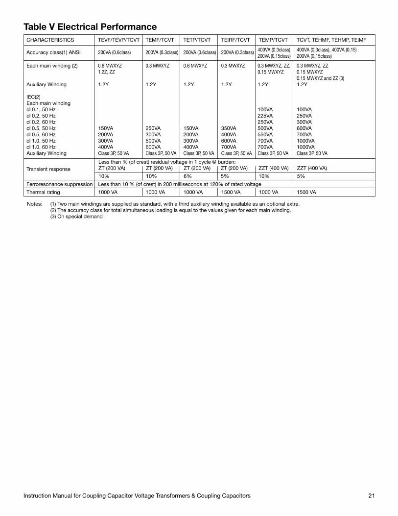
Table V Electrical PerformanceCHARACTERISTICS TEVF/TEVP/TCVT TEMF/TCVT TETP/TCVT TEIRF/TCVT TEMP/TCVT TCVT, TEHMF, TEHMP, TEIMF
Transient response
Thermal rating 1000 VA 1000 VA 1000 VA 1500 VA 1000 VA 1500 VA
Accuracy class(1) ANSI 200VA (0.6class) 200VA (0.3class) 200VA (0.6class) 200VA (0.3class) 400VA (0.3class) 400VA (0.3class), 400VA (0.15) 200VA (0.15class) 200VA (0.15class)
Each main winding (2) 0.6 MWXYZ 0.3 MWXYZ 0.6 MWXYZ 0.3 MWXYZ 0.3 MWXYZ, ZZ, 0.3 MWXYZ, ZZ 1.2Z, ZZ 0.15 MWXYZ 0.15 MWXYZ 0.15 MWXYZ and ZZ (3)Auxiliary Winding 1.2Y 1.2Y 1.2Y 1.2Y 1.2Y 1.2Y
IEC(2)Each main windingcl 0.1, 50 Hz 100VA 100VAcl 0.2, 50 Hz 225VA 250VAcl 0.2, 60 Hz 250VA 300VAcl 0.5, 50 Hz 150VA 250VA 150VA 350VA 500VA 600VAcl 0.5, 60 Hz 200VA 300VA 200VA 400VA 550VA 700VAcl 1.0, 50 Hz 300VA 500VA 300VA 600VA 700VA 1000VAcl 1.0, 60 Hz 400VA 600VA 400VA 700VA 700VA 1000VAAuxiliary Winding Class 3P, 50 VA Class 3P, 50 VA Class 3P, 50 VA Class 3P, 50 VA Class 3P, 50 VA Class 3P, 50 VA
Notes: (1) Two main windings are supplied as standard, with a third auxiliary winding available as an optional extra. (2) The accuracy class for total simultaneous loading is equal to the values given for each main winding. (3) On special demand
Ferroresonance suppression Less than 10 % (of crest) in 200 milliseconds at 120% of rated voltage
10% 10% 6% 5% 10% 5%
Less than % (of crest) residual voltage in 1 cycle @ burden:ZT (200 VA) ZT (200 VA) ZT (200 VA) ZT (200 VA) ZZT (400 VA) ZZT (400 VA)

Instruction Manual for Coupling Capacitor Voltage Transformers & Coupling Capacitors22
For after sales assistance:
Please contact Trench Limited and provide the following information for the unit in question:
• Type of unit • Serial number • Trench shop order number
Note all this information is available from the main nameplate. Please supply the informationregarding the problems or questions you may have.
www.trenchgroup.com


Global Trench Facilities
www.trenchgroup.com
trench® austria GmbHPaschinger Strasse 49Postfach 13AT-4060 Linz-Leonding AustriaPhone: 43-732-6793-0Fax: 43-732-671341
trench® chinaMWB (Shanghai) Co., Ltd.No. 3658, Jiancheng RoadMinhang, ShanghaiPeoples Republic of China200245Phone: 86-21-54720088Fax: 86-21-54723118
trench® shenyangTrench High Voltage Products Ltd., ShenyangNo. 2 Zhengliang Er Rd.,Jing Shen Xi San Str.Dao Yi Economic Development ZoneShenyang 110135Peoples Republic of ChinaPhone: 86-24-89722688Fax: 86-24-89737200
trench® limitedBushing Division432 Monarch AvenueAjax, OntarioCanada L1S 2G7Phone: 905-426-2665Fax: 905-426-2671
trench® limitedCoil Product Division71 Maybrook DriveScarborough, OntarioCanada M1V 4B6Phone: 416-298-8108Fax: 416-298-2209
trench® limitedInstrument Transformer Division390 Midwest RoadScarborough, OntarioCanada M1P 3B5Phone: 416-751-8570Fax: 416-751-6952
trench® limitedPower Line Carrier Division330 Finchdene SquareScarborough, OntarioCanada M1X 1A5Phone: 416-847-5400Fax: 416-291-5581
trench® France s.a.16, Rue du Général CassagnouB.P. 80070 FR-68302St. Louis, Cedex, FrancePhone: 33-3 89-70-2323Fax: 33-3 89-67-2663
trench® Germany GmbHNürnberger Strasse 199D-96050 Bamberg, GermanyPhone: 49-951-1803-0Fax: 49-951-1803-224
trench® switzerland aGLehenmattstrasse 353CH-4052Basel, SwitzerlandPhone: 41-61-315-51-11Fax: 41-61-315-59-00
trench® Italia s.r.l.Strada Curagnata, 37IT-17014 BragnoCairo, Montenotte (SV)ItalyPhone: 39-019-5161-111Fax: 39-019-5161-401
THE PROVEN POWER.


![A positive-sequence current based directional relaying ......The CCVT is applied over high voltage system for sev-eral advantages [26, 27]. However, it is subjected to power system](https://img.pdfslide.us/doc/110x75/612200da56cfdf2edd38bf92/a-positive-sequence-current-based-directional-relaying-the-ccvt-is-applied.jpg)