Embed Size (px)
Citation preview
TABLE
MODEL: Model 0-100-1 EngTYPE:
Two-cycle air cooledNUMBER OF
CYLINDERSBORE: 3-3 /ieinch bore
STROKE: 3Va inch stroke PISTON
DISPLACEMENT:
MCCULLOCH ENGINE MANUALRear End — Magneto end
Left Side Determined by looking tow ards
propeller from rear end
Right Side
Top Side — Carburetor side of engineCOMPRESSION RATIO: 8 to 1 CRANKSHAFT ROTATION: Clockwise
PROPELLER HUB BOLT CIRCLE SIZE: 4 inch dia. PROPELLER
HUB KEYWAY: Vi inch. NUMBER OF ENGINE MOUNTING EYE.S:
Three SIZE OF ENGINE MOUNTING EYES: 1 inch WEIGHT OF
ENGINE COMPLETE: 83 lbs. OVERALL DIAMETER OF ENGINE:
27'in. OVERALL LENGTH OF ENGINE: 26'A in.
POSITION OF CENTER OF GRAVITY: Seven inches forward from rear surface of engine
mounting eyes, and vertically through the center of the carburetor venturi tube.
72 H.P. developed at 4100 R.P.M. rated H.P.
MAGNETO SPEED: One to one
MAGNETO BREAKER POINT GAP: .018 inch
SPARK PLUG GAP: .018 inch
SPARK PLUG TYPE: RB916-S (BG Corp.)
Spark occurs in degrees before top center — 25 degrees.
FUEL MIXTURE: Ten to one
TYPE OF FUEL: 115-145 octane
or McCulloch 2 cycle engine oil
ACCESSORY WEIGHTS
Carburetor: 3 lb.
Ignition complete: 9 lb. Fuel
Pump: .9 lb.
Basic Engine: 66 lb.
Propeller Hub: 4 lb.
1-7. PROPELLER ROTATION. (See f igure 1-1.) The propeller is directly
attached to the crankshaft, and direction of rotation is clockw ise w hen
view ed from the rear of the engine.
1-8. CYLINDER DESIGNATION. (See f igure 1-1.) Engine cylinders are
designated by numbers as follow s:
CYLINDER NO. 1
2
3
4
LOCA T1 ON
Left front
Right front
Left rear
Right rear
SECTION I
INTRODUCTION
1-1. IDENTIFICATION.
1-2. This publication is issued as the basic Handbook of Overhaul
Instructions for the AAodel 0-100-1 Engine Assembly (AAcCulloch
AAodel 4318A), manufactured by AAcCulloch AAotors Corporation,
6101 West Century Boulevard, Los Angeles 45, California.
1-3. SCOPE OF INFORMATION.
1-4. This handbook contains descriptive data and illustrations to facilitate
understanding of the subject equipment and its individual components.
Information relative to construction, maintenance and overhaul is
contained herein. Section XII is a Table of Limits w hich contains useful
information relative to overhaul measurements and tolerances.
1-5. BASIC OPERATIONAL CHARACTERISTICS.
1-6. ENGINE ORIENTATION. In this publication the follow ing terminology
w ill be used in location of engine
1-9. MAGNETO ROTATION. The magneto is driven 1-11. Minor differences exist betw een early and late serial directly by and rotates in the same
direction as the engine numbers of the 0-100-1 engine. The differences are confined crankshaft. primarily to the magneto and carburetor and are
noted
1/29/2011 gyrowiki.com/Shared Documents/Web …
gyrowiki.com/…/Untitled0.htm 1/18
throughout the book as necessary. Otherw ise, instructions 1-10. MODEL
DIFFERENCES. in the handbook are applicable to all Model 0-100-1 engines.
SECTION II GENERAL
DESCRIPTION
2-1. GENERAL DESCRIPTION.
2-2. FUNCTIONAL. The Model 0-100-1 Engine is a four-cylinder,
opposed-type, air-cooled engine w hich operates on the conventional
tw o-cycle principle. It is designed primarily to furnish pow er for
propulsion of radio-controlled pilotless aircraft for target or guided
missile purposes.
2-3. PHYSICAL. Figure 1-1 illustrates the 0-100-1 engine and identif ies
the major components. Equipment construction is covered in paragraph
2-5.
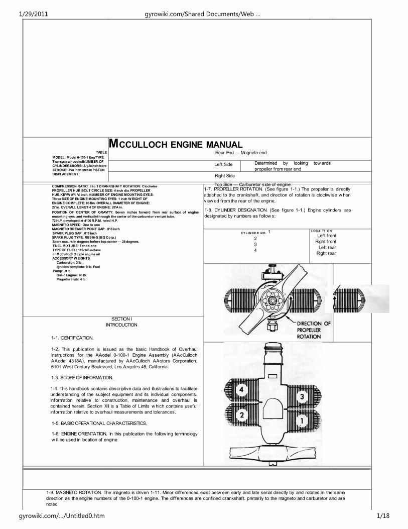
2-4. OPERATIONAL. As illustrated in f igure 2-1, the engine crankshaft is
designed to function as a rotary valve to meter fuel into the front and
rear crankcase chambers. From the crankcase the fuel is forced into the
combustion chambers, then detonated on the compression stroke.
Exhause action occurs near the end of the pow er stroke, then a new
fuel charge enters the combustion chambers from the crankcase and
the cycle is repeated. The engine is so constructed that the opposite
cylinders f ire together, and the front and rear cylinder pairs f ire
alternately, 180 degrees apart, to provide smoother engine operation.
POSITION 1-Crankshaft shown 25° before POSITION 2-Crankshaft shown 180° later,
top center on No. 1 and No. 2 cylinders. In In this position crankshaft cutout permits fuel
this position crankshaft cutout permits fuel to to enter rear half of crankcase only, enter front half of crankcase
only.
Figure 2-1. Crankshaft Function as Rotary Valve
14 POPULAR ROTORCRAFT
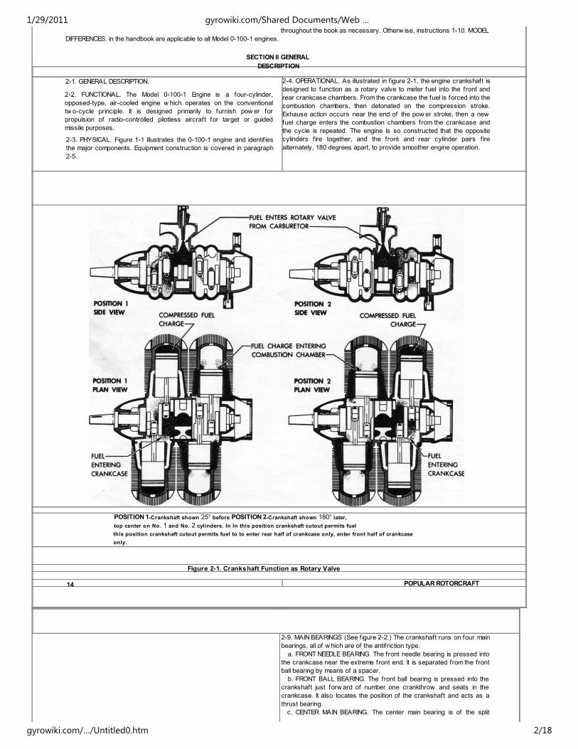
2-9. MAIN BEARINGS (See f igure 2-2.) The crankshaft runs on four main
bearings, all of w hich are of the antif riction type.
a. FRONT NEEDLE BEARING. The front needle bearing is pressed into
the crankcase near the extreme front end. It is separated from the front
ball bearing by means of a spacer.
b. FRONT BALL BEARING. The front ball bearing is pressed into the
crankshaft just forw ard of number one crankthrow and seats in the
crankcase. It also locates the position of the crankshaft and acts as a
thrust bearing.
c. CENTER MAIN BEARING. The center main bearing is of the split
1/29/2011 gyrowiki.com/Shared Documents/Web …
gyrowiki.com/…/Untitled0.htm 2/18
needle bearing type and is housed in an aluminum housing. It is located
betw een number tw o and number three crankthrow s. The center main
bearing housing is also split to accommodate the needle bearing w hich
locates in the center of the bore. At each end of the bore a series of
grooves is provided to form a pressure seal betw een the front and rear
crankcase sections. The w hole bearing assembly is held together by
means of four through-bolts and elastic stop nuts. The assembly is held
in alignment by means of tw o dow els. The complete assembly is located
in the large bore of the crankcase and held in place by means of a
special key w hich enters from the rigfvf bottom side of the crankcase.
The center main bearing housing is provided w ith a port on each end,
w hich forms the stationary part of the intake rotary valve.
d. REAR MAIN BEARING. The rear ball bearing is of the same type and
size as the front ball bearing and is pressed on the shaft just to the rear
of number four crankthrow . It seats in the crankcase rear cover
assembly and also locates the position of the crankshaft.
2-10. REAR COVER. The crankcase rear cover is cast of aluminum and
machined to f it the rear end of the crankcase. It is held in place by six
elastic stop nuts. The rear cover houses the magneto drive coupling.
Bores are provided for the crankshaft rear ball bearing and an oil seal. A
pad is machined on the rear side of the cover to mount the magneto
assembly. The magneto mounting studs are screw ed into the rear cover.
A small hole w hich guides the fuel pump upper plunger is provided at the
bottom of the cover. The third engine mounting lug is located at the top of
the rear cover.
2-11. CONNECTING RODS. The connecting rods are forged of SAE 4615
steel w ith hardened and precision ground bores. They are f itted at the
crankshaft end w ith 18 loose bearing rollers w hich run in specially
designed beryllium copper cages. The cap is secured to the connecting
rod by means of tw o special bolts and nuts. The nuts are secured by
locking plates. Tw o needle bearings are pressed into the piston pin bore
of the connecting rod to accommodate the piston pin. The sides of the
crankshaft end of the connecting rod are grooved to allow admission of
lubricant to the bearings.
2-12. PISTONS AND PISTON PINS. The pistons are constructed of
aluminum and are graphite impregnated. Each piston has tw o
compression ring grooves near the top. Piston pins are made of SAE
3115 steel, hardened and ground. Each pin is hollow throughout most of
its length to reduce w eight. The piston pin f loats in the connecting rod
needle bearing and is a press f it in the piston. It is retained in the piston
by means of one spring w ire snap ring at each end.
NEEDLE BEARING NEEDLE BEARING
Figure 2-2. Main Bearing Location 2-5.
DETAILED DESCRIPTION.
2-6. CYLINDER CONSTRUCTION. The four identical engine cylinders are
constructed of die cast aluminum w ith integral cooling f ins and a chrome
plated bore. Cylinders mount on the crankcase by means of studs and
nuts w hich mate w ith four holes in the cylinder mounting pads. Cylinders
are interchangeable for all four positions on the engine.
2-7. CRANKSHAFT CONSTRUCTION. The crankshaft is forged of SAE
4615 steel, w ith main bearing journals drilled through to reduce w eight.
Transfer of crankcase pressure is prevented by means of four cup
plugs pressed in the crankshaft centerline hole. The bearing journals are
hardened and precision ground. A cam, w hich actuates the fuel pump
plunger, is provided at the rear end of the crankshaft. A Woodruff
keyw ay is also provided at the rear end to drive the magneto coupling.
The front end of the crankshaft is provided w ith an SAE No. 00 taper
and square keyw ay for mounting the propeller hub. It is threaded in the
end to accommodate a s/B-18 NF propeller hub retaining thrust bolt. The
tw o integral scalloped cheeks at the center of the crankshaft form the
rotating part of the intake rotary valve w hich governs the admittance of
the fuel charge of the crankcase sections.
2-8. CRANKCASE. The crankcase is an aluminum casting in w hich
suitable bores are provided for the crankshaft main bearings. The
extreme front end is bored to accommodate an oil seal. The right and left
sides of the crankcase are bored for cylinder openings and machined to
form the cylinder mounting pads. The cylinder mounting studs are
screw ed into the crankcase. The rear end of the crankcase is bored
and machined to mount the rear cover assembly. The rear cover
mounting studs are screw ed into the crankcase. The carburetor
assembly mounts on the top of the crankcase on the pad machined for it.
The carburetor mounting studs are also screw ed into the crankcase. A
fuel pump mounting pad is provided at the bottom of the crankcase near
the rear end. This pad is machined to accommodate the fuel pump, fuel
pump low er plunger and plunger oil seal. A small pad is machined on the
low er right side of the engine for the center main bearing retaining key.
Tw o of the three engine mounting lugs are located at the bottom rear of
the crankcase.
DECEMBER 1975 15
2-13. COOLING SYSTEM. The engine is cooled by air flow over and
around the f inned cylinders.
2-14. LUBRICATION (Fuel Mixture). Lubrication is provided for the engine
by the oil mixed w ith fuel as in conventional tw o-cycle engines. No other
lubrication is required. This fuel-oil mixture consists of one part of oil, by
volume, Specification MIL-O-6082A, Grade 1065, thoroughly mixed w ith
securely pinned to it. Magnetos used on engine serials 43110327 and
above are equipped w ith a radio noise suppressor w hich is an integral
part of the electrical connector on the magneto.
b. COILS. Tw o coils are provided. The right hand coil f ires the tw o
right cylinders and the left hand coil the tw o left cylinders. The tw o front
cylinders f ire simultaneously as do the tw o rear ones 180 degrees later.
c. CONDENSER. The magneto is provided w ith a condenser w hich
1/29/2011 gyrowiki.com/Shared Documents/Web …
gyrowiki.com/…/Untitled0.htm 3/18
ten parts of fuel, by volume, Specif ication MIL-F-5572, Grade 115-145.
2-15. FUEL SYSTEM. The fuel system on the 0-100-1 engine consists of
a fuel pump mounted on the bottom of the engine, an interconnecting fuel
line w ith f ittings and a carburetor assembly mounted atop the engine. In
operation, fuel-oil mixture f low s from the target fuel tank through a fuel
f ilter and into the engine fuel pump. From here it is delivered to the
carburetor at a pressure of approximately 3V2 psi. In the carburetor, fuel
f irst passes through a mesh screen, then enters the diaphragm chamber
through the ball check valve.
2-16. FUEL PUMP. The fuel pump is an A.C. reciprocating diaphragm type
pump actuated by a plunger driven from a cam on the crankshaft. The
plunger consists of tw o parts, upper and low er, in line. The upper
plunger moves in the hole provided in the rear cover casting and the
bottom plunger moves in the crankcase. The fuel inlet connection is VB in.
U.S. standard pipe thread.
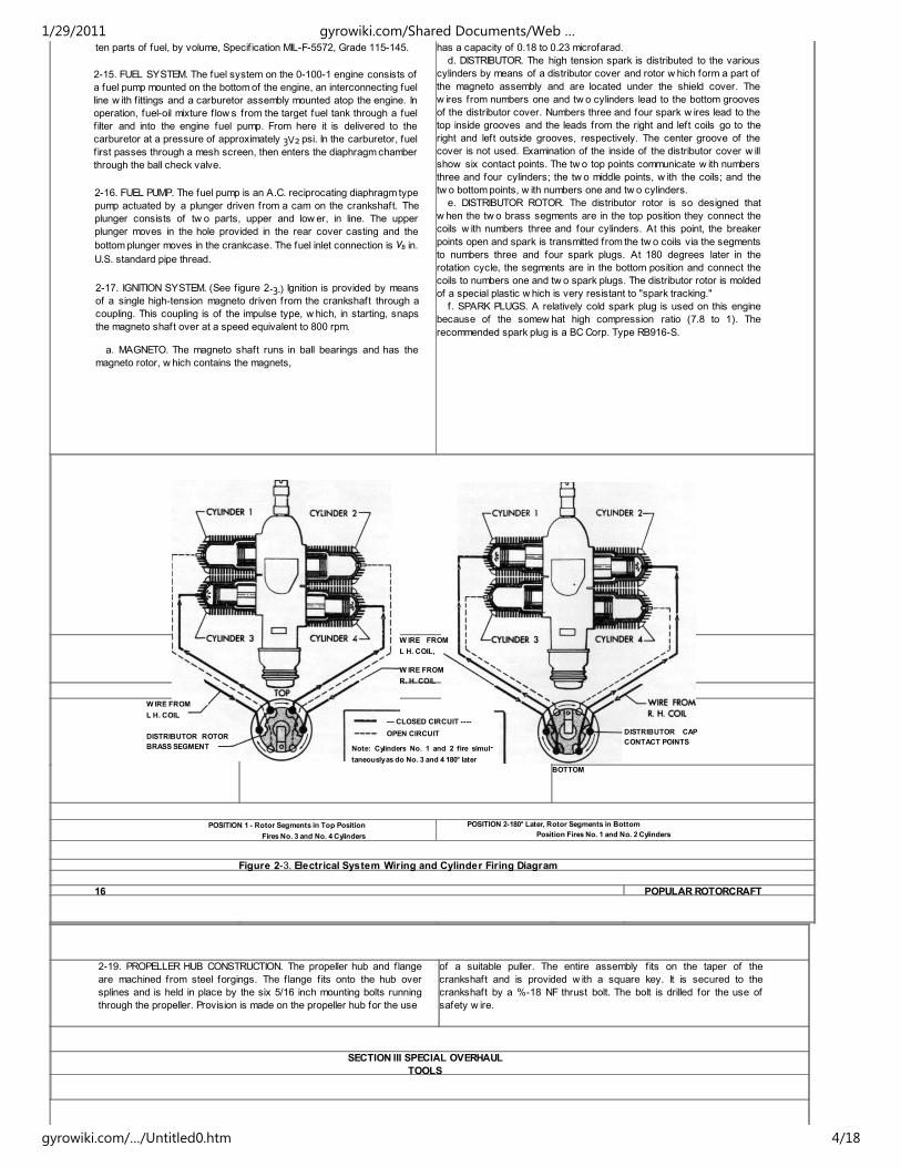
2-17. IGNITION SYSTEM. (See f igure 2‐3.) Ignition is provided by means
of a single high-tension magneto driven from the crankshaft through a
coupling. This coupling is of the impulse type, w hich, in starting, snaps
the magneto shaft over at a speed equivalent to 800 rpm.
a. MAGNETO. The magneto shaft runs in ball bearings and has the
magneto rotor, w hich contains the magnets,
has a capacity of 0.18 to 0.23 microfarad.
d. DISTRIBUTOR. The high tension spark is distributed to the various
cylinders by means of a distributor cover and rotor w hich form a part of
the magneto assembly and are located under the shield cover. The
w ires from numbers one and tw o cylinders lead to the bottom grooves
of the distributor cover. Numbers three and four spark w ires lead to the
top inside grooves and the leads from the right and left coils go to the
right and left outside grooves, respectively. The center groove of the
cover is not used. Examination of the inside of the distributor cover w ill
show six contact points. The tw o top points communicate w ith numbers
three and four cylinders; the tw o middle points, w ith the coils; and the
tw o bottom points, w ith numbers one and tw o cylinders.
e. DISTRIBUTOR ROTOR. The distributor rotor is so designed that
w hen the tw o brass segments are in the top position they connect the
coils w ith numbers three and four cylinders. At this point, the breaker
points open and spark is transmitted from the tw o coils via the segments
to numbers three and four spark plugs. At 180 degrees later in the
rotation cycle, the segments are in the bottom position and connect the
coils to numbers one and tw o spark plugs. The distributor rotor is molded
of a special plastic w hich is very resistant to "spark tracking."
f. SPARK PLUGS. A relatively cold spark plug is used on this engine
because of the somew hat high compression ratio (7.8 to 1). The
recommended spark plug is a BC Corp. Type RB916-S.
BOTTOM
POSITION 1 - Rotor Segments in Top Position
Fires No. 3 and No. 4 Cylinders
POSITION 2-180° Later, Rotor Segments in Bottom
Position Fires No. 1 and No. 2 Cylinders
Figure 2-3. Electrical System Wiring and Cylinder Firing Diagram
16 POPULAR ROTORCRAFT
2-19. PROPELLER HUB CONSTRUCTION. The propeller hub and f lange
are machined from steel forgings. The f lange f its onto the hub over
splines and is held in place by the six 5/16 inch mounting bolts running
through the propeller. Provision is made on the propeller hub for the use
of a suitable puller. The entire assembly f its on the taper of the
crankshaft and is provided w ith a square key. It is secured to the
crankshaft by a %-18 NF thrust bolt. The bolt is drilled for the use of
safety w ire.
SECTION III SPECIAL OVERHAUL
TOOLS
— CLOSED CIRCUIT ----
OPEN CIRCUIT
Note: Cylinders No. 1 and 2 fire simul����
taneously as do No. 3 and 4 180° later
W IRE FROM
L H. COIL,
W IRE FROM
R. H. COiL
W IRE FROM
L H. COIL
DISTRIBUTOR ROTOR
BRASS SEGMENT
DISTRIBUTOR CAP
CONTACT POINTS
1/29/2011 gyrowiki.com/Shared Documents/Web …
gyrowiki.com/…/Untitled0.htm 4/18
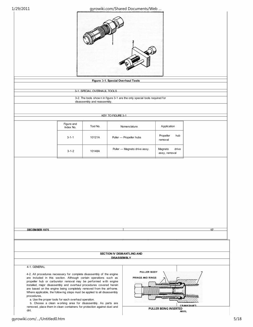
Figure 3-1. Special Overhaul Tools
3-1. SPECIAL OVERHAUL TOOLS
3-2. The tools show n in f igure 3-1 are the only special tools required for
disassembly and reassembly.
KEY TO FIGURE 3-1
Figure andIndex No. Tool No. Nomenclature Application
3-1-1 10121A Puller — Propeller hubsPropeller hub
removal
3-1-2 10148APuller — Magneto drive assy. Magneto drive
assy, removal
DECEMBER 1975 17
SECTION IV DISMANTLING AND
DISASSEMBLY
4-1. GENERAL
4-2. All procedures necessary for complete disassembly of the engine
are included in this section. Although certain operations such as
propeller hub or carburetor removal may be performed w ith engine
installed, major disassembly and overhaul procedures covered herein
are based on the engine being completely removed from the airframe.
Where applicable, the follow ing steps must be applied to all disassembly
procedures.
a. Use the proper tools for each overhaul operation.
b. Choose a clean w orking area for disassembly. As parts are
removed, place them in clean containers for protection against dust and
dirt.
PULLER BODY
PRINGS AND RINGS
CRANKSHAFT-
ANVILPULLER BEING INSERTED
1/29/2011 gyrowiki.com/Shared Documents/Web …
gyrowiki.com/…/Untitled0.htm 5/18
c. Carefully note manner of lockw iring so it may be duplicated on
reassembly.
NOTE
During the various stages of disassembly, close at����tention must be given to the parts as they are
removed from the engine and any abnormal wear,
defects or damage should be noted. Close
observation must be made of all components for
signs of scoring or burning through undue friction.
Many indications of defects are obscured by the
presence of dirt, carbon deposits, etc., and can only
be discovered after the various parts have been
cleaned. Any indication of work incorrectly
performed on a previous overhaul should be
reported immediately in the proper manner.
4-3. DETAILED.
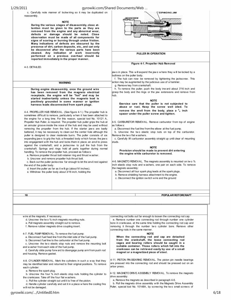
PULLER IN OPERATION
Figure 4-1. Propeller Hub Removal
jaw s in place. This w ill expand the jaw s w here they w ill be locked by a
buttress on the puller body.
f. The hub can now be removed by tightening the jackscrew . This
action may be augmented by the judicious use of a hammer.
g. Remove key from crankshaft.
h. To remove the puller, push the body inw ard about 3'16 inch and
grasp the body and the rings or the jaw extensions and remove from
hub.
NOTE
Exercise care that the puller is not subjected to
abuse or rust. Keep the screw well oiled. To
remove the anvil from the body, place a 14 inch
spacer under the puller screw and tighten.
4-5. CARBURETOR REMOVAL. Remove carburetor from top of engine
as follow s:
a. Disconnect the fuel line from the elbow at the fuel pump.
b. Unscrew the tw o elastic stop nuts on top of the carburetor.
Remove the tw o f lat w ashers.
c. Carefully lif t carburetor assembly straight up until clear of mounting
studs.
NOTE
Provision should be made to prevent dirt enteringthe engine while carburetor is removed.
4-6. MAGNETO REMOVAL. The magneto assembly is mounted on tw o %
inch elastic stop nuts and w ashers, one pair on each side. To remove
the magneto assembly:
a. Disconnect all four spark plug leads at the spark plugs.
b. Remove shielding harness attachment to the engine.
c. Disconnect the ignition sw itch w ire and the ground
WARNING
During engine disassembly, once the ground wire
has been removed from the magneto electrical
receptacle, the engine will be "hot" and may be
started inadvertantly unless the magneto lead is
positively grounded in some manner or ignition
harness leads disconnected from spark plugs.
4-4. PROPELLER HUB REMOVAL. (See f igure 4-1.) The propeller hub is
sometimes diff icult to remove, particularly w hen it has been attached to
the engine for a long time. For this reason, special tool No. 10121 A,
Propeller Hub Puller, is required. The propeller hub puller grips the hub at
an annular groove inside the nose of the hub and may be used w ithout
removing the propeller from the hub. If the starter jaw s are badly
battered, it may be necessary to clean out the center hole although the
puller is designed to clear moderate burrs. The puller consists of six
expanding jaw s to grip the hub; a threaded body w hich forces the jaw s
into engagement w ith the hub and locks them in place; an anvil to press
against the crankshaft; and a jackscrew to pull the hub from the
crankshaft. Springs and rings hold all parts together during normal
handling. To remove the propeller hub, proceed as follow s:
a. Remove propeller thrust bolt retainer ring and thrust w asher.
b. Unscrew and remove propeller hub thrust bolt.
c. Back out the puller jackscrew far enough to let the anvil rest against
the end of the puller body.
d. Insert the puller as far as it w ill go (about IVi inches).
e. Withdraw the puller body about 3/16 inch, holding the
18 POPULAR ROTORCRAFT
w ire at the magneto, if necessary.
d. Unscrew the tw o %-inch magneto mounting nuts.
e. Pull magneto assembly straight out to remove.
f. Remove rubber magneto drive coupling insert.
4-7. FUEL PUMP REMOVAL. To remove the fuel pump:
a. Disconnect fuel feed line from the inlet side of the fuel pump.
b. Disconnect fuel line to the carburetor at the fuel pump.
c. Unscrew the tw o elastic stop nuts and remove the mounting bolt
and w asher from each side of the fuel pump.
d. Carefully slide pump forw ard to disengage pump arm from push rod
and housing. Remove gasket.
4-8. CYLINDER REMOVAL. Mark the cylinders in such a w ay that they
may be identif ied later and returned to their original positions. To remove
each cylinder:
a. Remove the spark plug.
b. Unscrew the four % inch elastic stop nuts holding the cylinder to
the crankcase. Take off the four f lat w ashers.
c. Pull the cylinder straight out until it is free of the piston.
d. Handle cylinder carefully and set it in a place w here the cooling f ins
w ill not be damaged.
connecting rod bolts out far enough to loosen the connecting rod cap.
e. Remove number one connecting rod through number one cylinder
bore in crankcase, at the same time holding the connecting rod cap and
removing it through the number tw o cylinder bore. Remove other
connecting rods in the same manner.
NOTE
When the connecting rod and cap are detached
from the crankshaft, the loose connecting rodcages and bearing rollers should be caught in a
suitable container. Those rollers which fall into the
crankcase can be retrieved easily by use of a small
magnet or a magnetized piece of steel.
4-11. PISTON PIN BEARING REMOVAL. The piston pin needle bearings
are pressed into the connecting rod and should be pressed out on an
arbor press.
4-12. MAGNETO DRIVE ASSEMBLY REMOVAL. To remove the magneto
drive assembly:
a. Remove the magneto as described in paragraph 4-6.
b. Pull the magneto drive assembly w ith the Magneto Drive Assembly
Puller, special tool No. 10148A, by screw ing the tw o small screw s of
JACKSCREW
EXPANDING JAW
PROPELLE
1/29/2011 gyrowiki.com/Shared Documents/Web …
gyrowiki.com/…/Untitled0.htm 6/18
e. Remove the cylinder gasket.
NOTE
If the pistons are not to be removed immediately,
cover the top and bottom studs with a protective
device such as a short length of rubber tubing to
prevent these studs from scratching the piston
while moving it in or out of the crankcase.
4-9. PISTON REMOVAL. Before removing pistons, mark each piston to its
related cylinder to insure correct replacement. Proceed w ith piston
removal as follow s:
NOTE
The pistons are more readily removed if all the
cylinders are dismounted.
a. Remove the snap ring in one end of the piston pin bore by inserting
a narrow screw driver under the snap ring in the groove provided and
prying out the ring.
b. With piston properly supported, carefully drive out the piston pin,
using a w ooden dow el and a small hammer.
c. Slide piston aw ay from connecting rod.
d. If removal is necessary, pry out snap ring and the tw o piston rings,
using extreme care to avoid damage to piston, ring lands.
4-10. CONNECTING ROD REMOVAL. A connecting rod can be removed
only after the opposing cylinder has been removed. To remove number
one connecting rod, for example, both number one and number tw o
cylinders must be removed. In most cases, the w ork is facilitated by
removing the piston also. Mark rod for cylinder identif ication, then
proceed as follow s:
a. Rotate crankshaft by hand until the connecting rod nuts on number
one rod are accessible through the number tw o cylinder crankcase
bore.
b. Using a small punch and hammer, straighten the f langes on the lock
plates securing the connecting rod nuts.
c. Unscrew and remove both connecting rod nuts, using a 7/16 inch
socket w rench. Take off lock plates.
d. Using a small punch and hammer, drive the tw o
the puller into the holes provided in the drive assembly and screw up the
center screw to pull the drive assembly until it is clear of the crankshaft.
c. Remove the Woodruff key from the keyw ay in the crankshaft w ith
a pair of pliers.
4-13. REAR COVER REMOVAL. Fuel pump must be removed prior to
removal of the engine rear cover. To remove the rear cover casting:
a. Using a pair of long-nosed pliers, remove the fuel pump low er
plunger through the round hole in the fuel pump mounting boss on the
engine crankcase.
b. Unscrew and remove the six 5/16 inch elastic stop nuts holding the
cover in place. Remove w ashers.
c. Hold fuel pump upper plunger in place w hile starting to pull cover.
d. The rear cover is a comparatively close f it in the crankcase. To
loosen cover, tap gently and evenly around the mating circumference
w ith a rubber mallet.
e. Slide cover aw ay from crankcase w hen it becomes suff iciently
loose. After cover is free the enclosed fuel pump upper plunger can be
extracted.
f. Remove rear cover gasket.
4-14. CRANKSHAFT REMOVAL. Remove the crankshaft as follow s:
a. Unscrew the tw o '/4 inch hex head cap screw s and remove the
cover over the key in the low er right hand side of the crankcase.
b. Remove the key by screw ing a V2-20 screw into key and pulling it
from crankcase.
c. While supporting the rear end of the crankshaft, drive it backw ards
by striking the taper end of the crankshaft w ith a rubber mallet. If the
crankshaft is still not free of the engine after the taper end is driven into
the crankcase, continue the driving procedure using a brass or copper
rod until the crankshaft is free and can be pulled out.
NOTE
If it is desired to remove the crankshaft but not
entirely disassemble it, the magneto drive coupling,
rear cover, magneto and the crankshaft can all be
driven
DECEMBER 1975 19
out as one assembly. To remove the crankshaft in
this manner, remove the fuel pump lower plunger,
unscrew the six elastic stop nuts holding the rear
cover in place, remove the center main bearing key
and proceed to drive the crankshaft out as
described above. By this method it is not necessary
to remove the magneto, magneto drive coupling or
disassemble the rear cover in any manner.
4-15. CENTER MAIN BEARING REMOVAL. To remove the center main
bearing:
a. Unscrew the four 14 inch elastic stop nuts using an extension
socket w rench and drive out the four bolts through the main bearing
cage.
b. Separate the tw o halves of the aluminum cage by tapping them first
w ith a rubber mallet and then prying them apart at the parting line.
c. Separate the inner needle bearing cage and remove both the cage
and the needle bearings.
4-16. MAIN BALL BEARINGS REMOVAL. To remove the main ball
bearings, press them off the crankshaft using an arbor press.
4-17. PROPELLER HUB DISASSEMBLY. To completely disassemble hub
components, remove the attaching nuts, w ashers, and bolts through the
propeller and detach the hub and front f lange from the propeller.
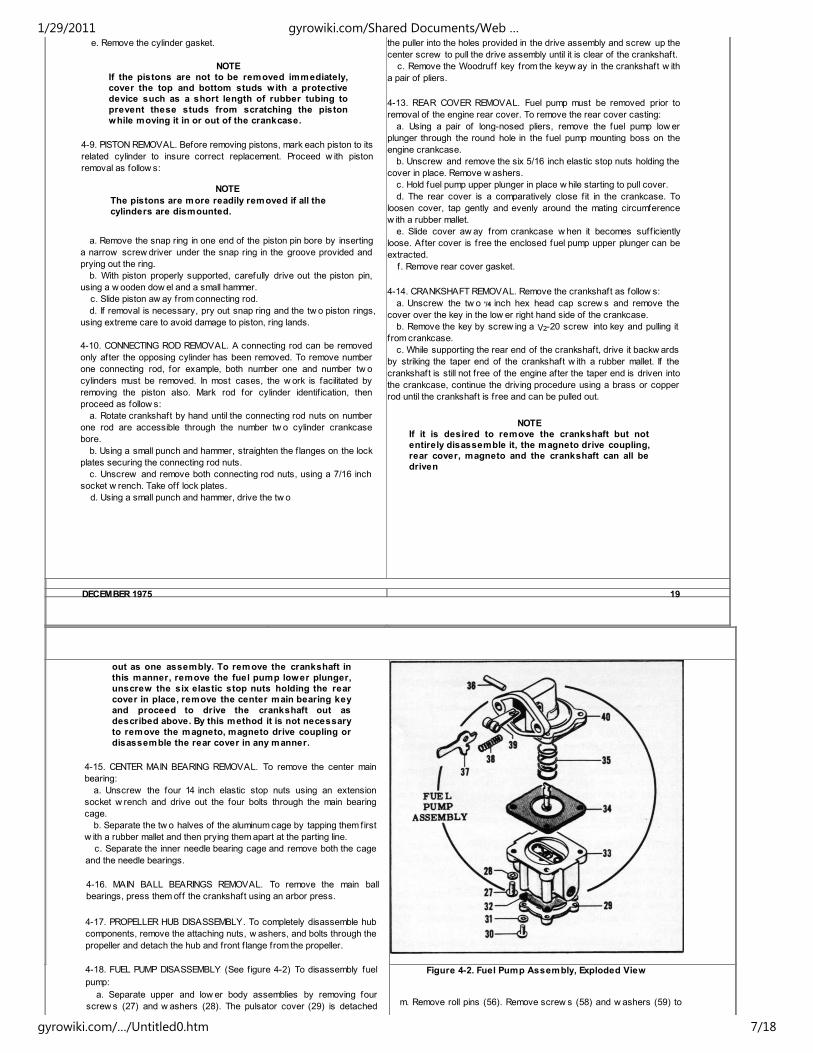
4-18. FUEL PUMP DISASSEMBLY (See f igure 4-2) To disassembly fuel
pump:
a. Separate upper and low er body assemblies by removing four
screw s (27) and w ashers (28). The pulsator cover (29) is detached
Figure 4-2. Fuel Pump Assembly, Exploded View
m. Remove roll pins (56). Remove screw s (58) and w ashers (59) to
1/29/2011 gyrowiki.com/Shared Documents/Web …
gyrowiki.com/…/Untitled0.htm 7/18
from the pulsator diaphragm (32) and upper pump body (33) by
removing four screw s (30) and w ashers (31).
b. Tw ist diaphragm assembly (34) one-quarter turn to disengage from
rocker arm link (39) and release diaphragm spring (35).
c. Drive out rocker arm pin (36) to release rocker arm (37), spring
(38) and link (39) from low er pump body (40).
detach coil and lamination assembly (57).
4-20. CRANKCASE DISASSEMBLY. The oil seal in the noise of the
crankcase is driven out by means of a long punch from the inside of the
crankcase. The needle bearing and the spacer in the front end of the
crankcase can then be driven out from the outside of the crankcase.
Small items such as plugs can be removed as necessary.
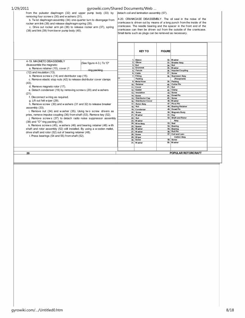
KEY TO FIGURE
1. Sleeve 32. Washer
2. Elbow 33. Breaker Assy.
3. Nut 34. Nut
4. Grommet 35. Washer
5. Ferrule 36. Impulse Coupling
6. Cable 37. Screw
7. Fitting 38. Supressor Assy.CO Packing (Receptacle)
9. Metal Hose 39. Packing
10. Retainer 40. Cotter Pin
11. Cover 41. Nut
12. Gasket 42. Clamp
13. Insulation 43. Screw
14. Screw 44. Dowel Pin
15. Distributor Cap 45. Screw
16. Distributor Cover 46. Washer
17. Rotor Assy. 47. Pivot Pin
18. Nut 48. Bearing Retainer
19. Condenser 49. Dowel Pin
20. Screw 50. Magneto Body
21. W asher 51. Key
22. Nut 52. Shaft and Rotor
23. W asher Assy.
24. W ire Assy. 53. Seal
25. Spacer 54. Bearing
26. W asher 55. Bearing
27. W asher 56. Roll Pin
28. Screw 57. Coil and Lam-
29. W iper ination Assy.
30. Screw 58. Screw
31. W asher 59. Washer
4-19. MAGNETO DISASSEMBLY
disassemble the magneto:
a. Remove retainer (10), cover (1
(See figure 4-3.) To 'O"
ring packing(12) and insulation (13).
b. Remove screw s (14) and distributor cap (15).
c. Remove elastic stop nuts (42) to release distributor cover clamps
(43).
d. Remove magneto rotor (17).
e. Detach condenser (19) by removing screw s (20) and w ashers
(21).
f. Disconnect w iring as required.
g. Lif t out felt w iper (29).
h. Remove screw (30) and w ashers (31 and 32) to release breaker
assembly (33).
i. Remove nut (34) and w asher (35). Using tw o screw drivers as
pries, remove impulse coupling (36) from shaft (53). Remove key (52).
j. Remove screw s (37) to detach radio noise suppressor assembly
(38) and "O" ring packing (39).
k. Remove screw s (45), w ashers (46) and bearing retainer (48) w ith
shaft and rotor assembly (52) still installed. By using a w ooden mallet,
drive shaft and rotor (52) out of bearing retainer (48).
I. Press bearings (54 and 55) from shaft (52).
20 POPULAR ROTORCRAFT
1/29/2011 gyrowiki.com/Shared Documents/Web …
gyrowiki.com/…/Untitled0.htm 8/18

SECTION V
CLEANING
3-1. GENERAL. All parts of these engines, internal and external, can be thoroughly w ash all magneto internal parts (except condenser) w ith
1/29/2011 gyrowiki.com/Shared Documents/Web …
gyrowiki.com/…/Untitled0.htm 9/18
cleaned w ith kerosene, Federal Specif ication VV-K-211. This cleaning
can be in the form of a spray or immersion and w ashing w ith a soft
brush. Dry by blow ing w ith compressed air or w iping w ith a clean cloth.
5-2. CLEANING AFTER LANDING. Due to the open exhaust ports, dirt
and sand frequently enter the cylinders after a landing. This also applies
to the carburetor. To clean the engine after landing, disassemble the
dirty parts as described in Section IV and clean w ith kerosene as
specif ied in paragraph 5-1.
5-3. CLEANING AFTER IMMERSION.
5-4. ENGINE. No damage or impaired operation of the engine w ill result
from salt w ater immersion if the follow ing operations are performed
w ithout delay after removal of target from the w ater.
a. Remove engine from target and drain out salt w ater.
b. Remove magneto, carburetor and spark plugs, then completely
disassemble remainder of engine assembly as instructed in Section IV.
c. Take out crankcase drain plugs located at top and bottom of nose
bearing and ascertain that bearing cavity is drained thoroughly.
d. Immerse or w ash out crankcase and engine components w ith
clean, fresh w ater. Drain out all w ater, then clean all parts and. areas
completely w ith kerosene or gasoline and oil mixture. Dry thoroughly; if
necessary, use compressed air on areas such as nose bearing cavity
in crankcase.
e. Clean out carburetor as instructed in paragraph 5-5.
f. Check magneto for w ater as instructed in paragraph 5-7.
g. Overhaul spark plugs.
h. Reassemble engine and components as instructed in Sections VIII
and IX.
i. After reassembly, run engine at least f ive minutes, w ith propeller
installed, using an oil and fuel mixture having a minimum ratio of 1 to 10.
5-5. CARBURETOR. After removal, clean carburetor as follow s:
a. Immerse entire carburetor assembly in kerosene, Federal
Specif ication VV-K-211, to w ash out all dirt.
b. Dry carburetor external surfaces w ith a clean cloth or compressed
air.
5-6. MAGNETO. Remove band and cap and inspect magneto internally
for signs of leakage. If w ater is found, proceed as follow s:
a. Remove the tw o distributor cover elastic stop nuts and clamps and
move distributor cover back. Remove tw o screw s holding distributor
cap in place and remove cap. It is not necessary to detach w ires from
distributor cover.
b. Remove distributor rotor.
c. Blow out complete assembly w ith compressed air to remove any
trace of w ater.
d. Blow out distributor cover.
e. Using a small, soft brush or clean, lint-free cloth,
clean kerosene. Dry w ith compressed air.
f . Inspect points for burning or pitting and set point gap to 0.022 inch.
g. Check all w ires for deterioration of insulation.
h. Check inside and outside of distributor cover for cracks and check
cover contacts for evidence of tracking.
i. Check rotor for cracks and loose segments.
j. Replace rotor, making sure alignment lug is in line w ith slot in end of
shaft and that rotor is pushed f irmly in place.
k. Replace distributor cover, seating it f irmly in groove w ith locating
lug in correct position. Secure cover w ith the tw o elastic stop nuts and
clamps. Replace distributor cap and secure w ith tw o screw s.
I. Lubricate "O" ring packing liberally and replace cap and band,
making sure that cap and band are correctly seated.
5-8. CLEANING PISTONS AND CYLINDERS. Due to the open exhaust
ports, the cylinders and pistons frequently become dirty. In these cases,
remove the cylinders and pistons as described in paragraphs 4-8 and 4-
9. Wash thoroughly as specif ied in paragraph 5-1 above.
5-9. CARBON REMOVAL. Carefully scrape aw ay carbon deposits,
taking care not to scrape the metal and scratch machined surfaces.
Then w ash thoroughly w ith kerosene as specif ied in paragraph 5-1
above.
5-10. PISTON RING GROOVES. Piston ring grooves can be cleaned by
scraping aw ay the carbon w ith a small narrow scraper made of soft
metal or w ood. A broken piston ring can be used for this purpose by
grinding one end dow n to a sharp edge and sliding it along the groove.
5-11. PROTECTIVE MEASURES. If the parts are not to be used
immediately, apply a thin coating of oil, conforming to Specif ication MIL-
O-6082A (Grade 1065) to each part after the kerosene w ashing and
drying. Store in a clean place and cover securely.
SECTION VI
INSPECTION
6-1. GENERAL. When overhauling the engine, the various parts should
be given close attention in order to determine if any evidence of w ear,
scoring or defects is present. Often these indications are obsured due
to the presence of dirt, carbon deposits, etc., and can only be
discovered after the various parts have been cleaned. In most cases the
presence of serious defects is suff icient cause to reject the part.
Rejection of parts show ing minor defects is left to the discretion of the
person in charge. Some of the minor defects can be readily corrected or
repaired as described in Section VII.
6-2. PROPELLER HUB ASSEMBLY. Carefully inspect the taper bore of
the hub for evidence of "fretting" corrosion. This w ill be indicated usually
by reddish brow n discoloration of the inside of the taper bore. This
22 POPULAR ROTORCRAFT
discoloration w ill also be found on the taper portion of the crankshaft. It
is caused by a poorly f itted taper seat betw een the tw o parts or by the
propeller not being tightened sufficiently. Inspect the condition of the
threads on the propeller thrust bolt and also on the six propeller mounting
bolts.
6-3. MAGNETO INSPECTION. After the magneto is disassembled as
described in paragraph 4-19, inspect the distributor cap and cover for
cracks and evidence of "spark tracking." Check the distributor rotor for
loose segments. Observe the condition of the breaker points and
determine if any evidence of pitting or burning is present. Burning w ill be
indicated by dark discoloration of the points. Examine all w ires carefully
lack of lubrication. This w ill be indicated by heat discoloration. (See
Table of Limits, Section XII).
6-8. CONNECTING ROD ASSEMBLY. Check the connecting rod bearing
bores, particularly on the crankshaft end, for evidence of excessive
heating. Also, observe if any abrasion evidence is present. Inspect the
connecting rod forging itself for indications of physical failure such as
cracks. The bearing rollers should not be discolored and should be free
of f lat spots. (See Table of Limits, Section XII.) Assemble cap to rod and
tighten nuts to normal torque, then check to see that there is no ledge
w here cap and rod meet.
1/29/2011 gyrowiki.com/Shared Documents/Web …
gyrowiki.com/…/Untitled0.htm 10/18
for evidence of insulation abrasion and loose connections at the
terminals. Check the condition of the impulse coupling and inspect for
evidence of binding in its moving parts. Examine the condition of the
magneto shaft, particularly at the bearing points, for indications of
insuff icient lubrication or scoring. Test the condenser on a Condenser
Tester, particularly for dielectric leakage.
6-4. MAGNETO IMPULSE RUBBER COUPLING. Inspect for incipient
deterioration caused by the corrosive action of petroleum compounds on
rubber.
6-5. FUEL PUMP. Test the fuel pump by immersing the intake side of the
pump in kerosene and manually actuating the pump lever. If operating
properly, the pump should discharge a substantial amount of kerosene
w ith each stroke.
6-6. CYLINDER ASSEMBLY. Discard the cylinder if large pieces of
cooling f ins are broken off. Pay particular attention to the condition of the
cylinder mounting pad for evidence of cracks around the cylinder
mounting holes. Examine the cylinder bore for score marks, grooving or
abrasion.
6-7. PISTON ASSEMBLY. Inspect the pistons for scoring and evidence
of erosion due to excessive blow by. Check the piston rings for
indications of sticking. Examine the piston for nicks or cracks,
particularly around the skirt. Remove the piston pin and inspect for
abrasion and any evidence of
6-9. CRANKCASE ASSEMBLY. Carefully inspect the areas around the
cylinder mounting studs for cracks due to fatigue. Carefully examine the
engine mounting lugs for breaks or cracks, w hich are often caused by
abnormal landings. Observe the condition of the oil seal in the front of
the crankcase and replace if the leather appears to be w orn. Pay
particular attention to the needle bearing in the front of the crankcase
and examine it carefully for heat discoloration or corrosion. (See Table
of Limits, Section XII.)
6-10. REAR COVER ASSEMBLY. Inspect carefully for cracks or
fractures, especially around the upper cylinder mounting lug.
6-11. CRANKSHAFT ASSEMBLY. Carefully examine all bearing journals
on the crankshaft for evidence of heat or abrasion. Inspect for cracks or
other evidence of fatigue failure, especially in and around the corners of
the journals. Disassemble the center main bearing and check the con�
dition of the inner needle bearing. Inspect the aluminum bore, particularly
around the sealing grooves and also the faces of the rotary valve for
abrasion or evidence of metal pick-up. If the engine has been subjected
to hard landings, particularly on the front of the engine, examine the tw o
front throw s. After a hard nose landing, the tw o front throw s may be
pinched opposite the connecting rod journals. If possible, support the
crankshaft at the main bearing locations and check for excessive run-
out at the propeller end of the crankshaft. The maximum allow able TIR
run-out measured at the extreme end of the crankshaft is .002 8̂83 in
(See Table of Limits, Section XII.)
SECTION VII REPAIR AND
REPLACEMENT
CAUTION
It is not recommended that welding be used to
repair any portion of the engine because of the
distortion induced by this method. Seriously
damaged cylinders, crankcases, crankshafts, etc.,
should be replaced.
7-1. PROPELLER HUB REPAIR. Fretting corrosion, if not too serious, can
be corrected by dressing dow n the propeller shaft taper and the taper
bore of the propeller hub w ith f ine emery cloth. Then lap the hub on the
shaft, using a f ine lapping compound until a good f it is obtained.
NOTE
This method is not applicable to cases where
severe fretting is present, or where serious galling
has caused deep scores in the crankshaft taper.
The hub and flange constitutes a matched
assembly and should be installed and-or stored asa matched set.
7-2. MAGNETO REPAIR. If the magneto breaker points are pitted or
burned seriously, it is better to replace them. Minor pitting or burning can
be corrected by f iling the points w ith a breaker point f ile. Be sure the
points are f iled so they come together squarely. Then adjust the points
as described in paragraph 8-4h. Resolder any loose w ire terminals and
tape any bare spots on the w ire to prevent grounding. If the magneto
shaft show s indications of excessive heat at the bearing points, it may
be advisable to dress these places dow n w ith f ine emery cloth providing
the clearance limits in Table of Limits, Section XII, are not exceeded.
Replace the distributor rotor and-or the distributor cap if cracks in them
are observed. Replace the condenser if the capacitance is not betw een
0.18 and 0.23 microfarad or if it show s dielectric leakage.
DECEMBER 1975 23
7-3. MAGNETO IMPULSE RUBBER COUPLING. Replace the rubber insert
of the magneto impulse coupling if any cracks or breaks are observed or
if serious deterioration has started.
7-4. FUEL PUMP. After disassembly to extent outlined in paragraph 4-18,
all components should be examined for excessive w ear. Inspect springs
for signs of fatigue or cracks. Inspect diaphragm assembly for cracks or
excess hardening of diaphragm material. Replace any parts show ing
indications of possible defects.
7-5. CYLINDER REPAIR. No attempt should be made to repair damage to
the cylinder cooling f ins. Cylinder w ith large areas of cooling f ins
damaged or broken, particularly at or near the top of the cylinder, should
be immediately discarded. Sm~ll pieces of cylinder f in broken off should
not affect the coi ing of the cylinder. Carefully remove any
carbon deposits in the top of the cylinder and especially around the
exhaust ports. Cylinders having visible cracks on the mounting holes
should be replaced.
7-6. PISTON ASSEMBLY. Reject the piston if nicks or cracks are
discovered. Remove the carbon from the top of the piston and also from
the ring grooves as described in paragraphs 5-7 and 5-8. Minor
scratches and grooves can be removed by polishing the piston w ith
very f ine emery cloth, being careful to maintain the concentricity of the
piston, providing the clearance listed in Table of Limits, Section XII, is not
exceeded.
7-7. CONNECTING ROD ASSEMBLY. Any defects or misalignment found
in the connecting rod is suff icient cause for rejection of this part. Rods
can be straightened and reground.
1/29/2011 gyrowiki.com/Shared Documents/Web …
gyrowiki.com/…/Untitled0.htm 11/18
SECTION VIII ASSEMBLY OF SUB-
ASSEMBLIES
8-1. GENERAL. This section describes in detail the proper methods and
sequence of assembling the various parts w hich make, up the sub-
assemblies of the engine.
NOTE
It is important that the component parts be
thoroughly cleaned before assembling them. It is
also important that the various parts be assembled
in the order given.
8-2. CRANKCASE ASSEMBLY. To assemble the nose bearing into the
crankcase, f irst stand the crankcase, nose dow n, on the w ork table.
Working through the crankcase interior, install the needle bearing in the
crankcase nose and carefully tap into place until fully seated, using a
long brass or copper rod and hammer. Install the bearing spacer in the
same manner. Reposition the crankcase and press the oil seal into place
in the front end recess. If necessary, the oil seal may be driven into
place, using a soft mallet so as not to injure the seal.
8-3. FUEL PUMP ASSEMBLY. (See f igure 4-2.) To reassemble the fuel
pump:
a. Insert pin (36) into low er body (40) and drive in to partly engage
link (39).
b. Hold rocker arm (37) and spring (38) in position. Drive in pin (36)
until f lush w ith outer surface of low er body (40).
c. Insert diaphragm assembly (34) and spring (35) w ith f lat sides of
diaphragm stem perpendicular to pin (36). Diaphragm stem w ill slip into
slot of link (39) and w ill engage link w hen diaphragm assembly is given
one quarter turn.
8-4. MAGNETO ASSEMBLY. (See f igure 4-3.) To reassemble the
magneto:
a. Install coil and lamination assembly (57) in body (50) loosely w ith
screw s (58) and w ashers (59). Temporarily insert rotor (52) and, using
w ooden w edges, pry laminations outw ard and install roll pins (56).
Tighten screw s.
b. Press bearings (54 and 55) to shoulders on shaft (52) and press
the assembly into retainer (48).
c. Attach bearing retainer (48) to magneto body (50) w ith screw s
(45) and w ashers (46).
d. Install oil seal (53). Secure impulse coupling (36) on rotor shaft (52)
w ith key (51), w asher (35) and nut (34).
e. Slip breaker (33) over pivot pin (47) and secure w ith screw (30)
and w ashers (31 and 32).
f. Turn rotor shaft (52) until the breaker point follow er block rests on
the highest part of one of the cams.
g. Loosen screw (30) until breaker (33) moves freely.
h. Place an 0.022 feeler gage betw een the breaker points and move
breaker up or dow n until a slight drag is felt on the gage w hen sliding it
betw een the points. Tighten screw (30) and recheck points for 0.022
gap.
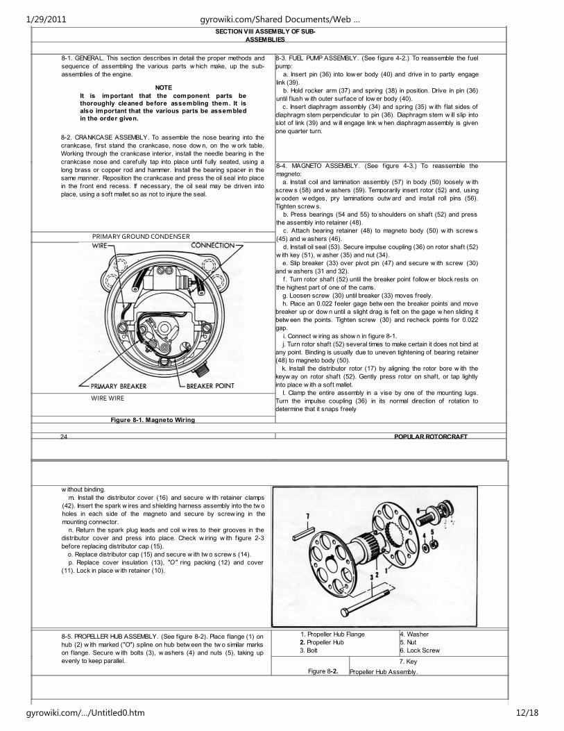
i. Connect w iring as show n in figure 8-1.
j. Turn rotor shaft (52) several times to make certain it does not bind at
any point. Binding is usually due to uneven tightening of bearing retainer
(48) to magneto body (50).
k. Install the distributor rotor (17) by aligning the rotor bore w ith the
keyw ay on rotor shaft (52). Gently press rotor on shaft, or tap lightly
into place w ith a soft mallet.
I. Clamp the entire assembly in a vise by one of the mounting lugs.
Turn the impulse coupling (36) in its normal direction of rotation to
determine that it snaps freely
PRIMARY GROUND CONDENSER
WIRE WIRE
Figure 8-1. Magneto Wiring
24 POPULAR ROTORCRAFT
w ithout binding.
m. Install the distributor cover (16) and secure w ith retainer clamps
(42). Insert the spark w ires and shielding harness assembly into the tw o
holes in each side of the magneto and secure by screw ing in the
mounting connector.
n. Return the spark plug leads and coil w ires to their grooves in the
distributor cover and press into place. Check w iring w ith f igure 2-3
before replacing distributor cap (15).
o. Replace distributor cap (15) and secure w ith tw o screw s (14).
p. Replace cover insulation (13), "O" ring packing (12) and cover
(11). Lock in place w ith retainer (10).
8-5. PROPELLER HUB ASSEMBLY. (See figure 8-2). Place f lange (1) on
hub (2) w ith marked ("O") spline on hub betw een the tw o similar marks
on f lange. Secure w ith bolts (3), w ashers (4) and nuts (5), taking up
evenly to keep parallel.
1. Propeller Hub Flange
2. Propeller Hub
3. Bolt
4. Washer
5. Nut
6. Lock Screw
Figure 8-2.
7. Key
Propeller Hub Assembly.
1/29/2011 gyrowiki.com/Shared Documents/Web …
gyrowiki.com/…/Untitled0.htm 12/18
SECTION IX FINAL
ASSEMBLY
9-1. GENERAL. It is assumed that at this stage of the overhaul
procedure all parts have been inspected and thoroughly cleaned. It is
further assumed that all of the subassemblies have been assembled as
described in Section VIII. In this section, unless otherw ise specif ied, all
references to oil shall mean engine oil, conforming to Specif ication MIL-
O-6082A (Grade 1065).
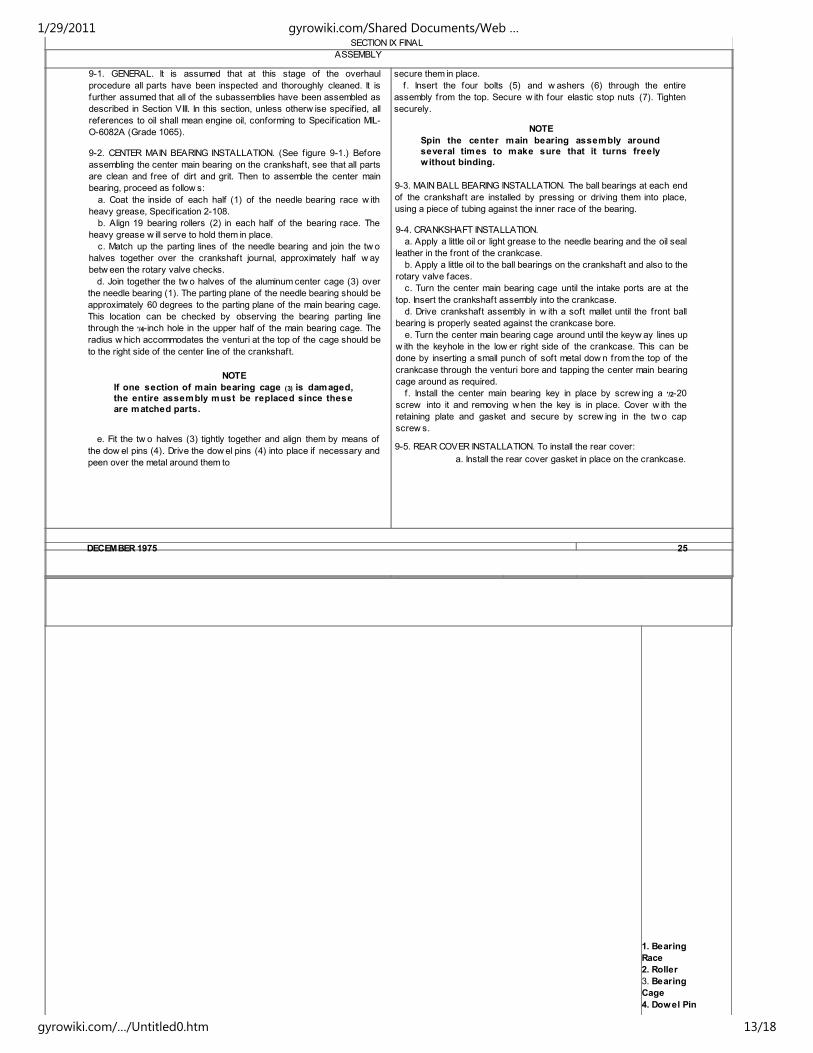
9-2. CENTER MAIN BEARING INSTALLATION. (See f igure 9-1.) Before
assembling the center main bearing on the crankshaft, see that all parts
are clean and free of dirt and grit. Then to assemble the center main
bearing, proceed as follow s:
a. Coat the inside of each half (1) of the needle bearing race w ith
heavy grease, Specif ication 2-108.
b. Align 19 bearing rollers (2) in each half of the bearing race. The
heavy grease w ill serve to hold them in place.
c. Match up the parting lines of the needle bearing and join the tw o
halves together over the crankshaft journal, approximately half w ay
betw een the rotary valve checks.
d. Join together the tw o halves of the aluminum center cage (3) over
the needle bearing (1). The parting plane of the needle bearing should be
approximately 60 degrees to the parting plane of the main bearing cage.
This location can be checked by observing the bearing parting line
through the '/4-inch hole in the upper half of the main bearing cage. The
radius w hich accommodates the venturi at the top of the cage should be
to the right side of the center line of the crankshaft.
NOTE
If one section of main bearing cage (3) is damaged,
the entire assembly must be replaced since these
are matched parts.
e. Fit the tw o halves (3) tightly together and align them by means of
the dow el pins (4). Drive the dow el pins (4) into place if necessary and
peen over the metal around them to
secure them in place.
f. Insert the four bolts (5) and w ashers (6) through the entire
assembly from the top. Secure w ith four elastic stop nuts (7). Tighten
securely.
NOTE
Spin the center main bearing assembly around
several times to make sure that it turns freely
without binding.
9-3. MAIN BALL BEARING INSTALLATION. The ball bearings at each end
of the crankshaft are installed by pressing or driving them into place,
using a piece of tubing against the inner race of the bearing.
9-4. CRANKSHAFT INSTALLATION.
a. Apply a little oil or light grease to the needle bearing and the oil seal
leather in the front of the crankcase.
b. Apply a little oil to the ball bearings on the crankshaft and also to the
rotary valve faces.
c. Turn the center main bearing cage until the intake ports are at the
top. Insert the crankshaft assembly into the crankcase.
d. Drive crankshaft assembly in w ith a soft mallet until the front ball
bearing is properly seated against the crankcase bore.
e. Turn the center main bearing cage around until the keyw ay lines up
w ith the keyhole in the low er right side of the crankcase. This can be
done by inserting a small punch of soft metal dow n from the top of the
crankcase through the venturi bore and tapping the center main bearing
cage around as required.
f. Install the center main bearing key in place by screw ing a '/2-20
screw into it and removing w hen the key is in place. Cover w ith the
retaining plate and gasket and secure by screw ing in the tw o cap
screw s.
9-5. REAR COVER INSTALLATION. To install the rear cover:
a. Install the rear cover gasket in place on the crankcase.
DECEMBER 1975 25
1. Bearing
Race
2. Roller
3. Bearing
Cage
4. Dowel Pin
1/29/2011 gyrowiki.com/Shared Documents/Web …
gyrowiki.com/…/Untitled0.htm 13/18
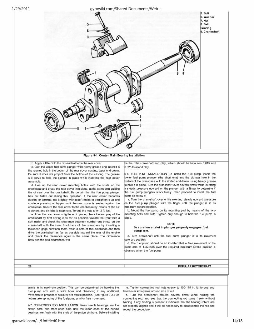
5. Bolt
6. Washer
7. Nut
8. Ball
Bearing
9. Crankshaft
Figure 9-1. Center Main Bearing Installation
b. Apply a little oil to the oil seal leather in the rear cover.
c. Coat the upper fuel pump plunger w ith heavy grease and insert it in
the reamed hole in the bottom of the rear cover casting, taper end dow n.
Be sure it does not project from the bottom of the casting. The grease
w ill serve to hold the plunger in place w hile installing the rear cover
assembly.
d. Line up the rear cover mounting holes w ith the studs on the
crankcase and press the rear cover into place, at the same time guiding
the oil seal over the crankshaft. Be certain that the fuel pump plunger
has not fallen out during this operation. If the rear cover becomes
cocked or jammed, tap it lightly w ith a soft mallet to straighten it up and
continue pressing or tapping until the rear cover is seated against the
crankcase. Secure the rear cover to the crankcase by means of the six
w ashers and six elastic stop nuts. Torque the nuts to 9-12 ft. lbs.
e. After the rear cover is tightened in place, check the end play of the
crankshaft by first driving it as far as possible tow ard the front w ith a
soft mallet and check the clearance betw een number one throw on the
crankshaft w ith the inner front face of the crankcase by inserting a
thickness gage betw een them. Make a note of this clearance and then
drive the crankshaft as far as possible tow ard the rear of the engine
and check the clearance again in the same place. The difference
betw een the tw o clearances w ill
be the total crankshaft end play, w hich should be betw een 0.015 and
0.025 total end play.
9-6. FUEL PUMP INSTALLATION. To install the fuel pump, insert the
low er fuel pump plunger (the short one) into the plunger hole in the
bottom of the crankcase w ith the slotted end dow n, using heavy grease
to hold it in place. Turn the crankshaft over several times w hile exerting
a steady pressure upw ard on the plunger w ith a f inger to determine if
the fuel pump plungers w ork freely. Then proceed to install the fuel
pump as follow s:
a. Turn the crankshaft over w hile exerting steady upw ard pressure
on the fuel pump plunger w ith the f inger until the plunger is in its
maximum inw ard position.
b. Mount the fuel pump on its mounting pad by means of the tw o
mounting bolts and nuts. Tighten only enough to hold the fuel pump in
place.
NOTE
Be sure lower slot in plunger properly engages fuelpump arm.
c. Turn crankshaft until the fuel pump plunger is in its maximum
outw ard position.
d. The fuel pump should be so installed that a free movement of the
pump arm of 1-32-inch over the required maximum stroke position is
obtained w hen the fuel pump
26 POPULAR ROTORCRAFT
arm is in its maximum position. This can be determined by hooking the
fuel pump arm w ith a w ire hook and observing if any additional
movement is present at full outw ard stroke position. (See f igure 9-2.) Do
not mistake springing of the fuel pump arm for free movement.
9-7. CONNECTING ROD INSTALLATION. Press needle bearings into the
piston bore, one from each side, until the outer ends of the needle
bearings are flush w ith the ends of the piston pin bore. Before installing
e. Tighten connecting rod nuts evenly to 100-115 in. lb. torque and
bend over lock-plates around side of nut.
f. Turn the crankshaft around several times w hile holding the
connecting rod, and see that the connecting rod turns freely w ithout
binding. If any binding is present, it indicates that the bearing rollers are
not properly aligned and it w ill be necessary to disassemble the rod and
repeat the procedure.
1/29/2011 gyrowiki.com/Shared Documents/Web …
gyrowiki.com/…/Untitled0.htm 14/18

the connecting rod, lay all the component parts, connecting rod, bearing
cages, and bearing rollers, out on a clean surface, preferably a clean
cloth. The connecting rods are marked "one, tw o, three and four" to
identify their position. The numeral on the connecting rod cap must be on
the same side as the numeral on the connecting rod. The entire
connecting rod is assembled w ith these numerals tow ard the top of the
engine. Proceed w ith the connecting rod installation as follow s:
a. Coat crankshaft journal w ith heavy grease and place one roller
cage on upper surface of journal w ith six rollers in place.
b. Press dow n connecting rod bolts until heads are seated. Place one
cage and six rollers in connecting rod cap in relative position to cage on
crankshaft journal. Place remaining cage and six rollers in relative
position in connecting rod. Use heavy grease to hold cages and rollers
in position.
c. Place connecting rod cap in position on crankshaft journal on one
side of engine and insert connecting rod assembly through from
opposite side. Line up rod and cap and press together.
d. Install the lock-plates in place over the connecting rod screw s and
screw on the connecting rod nuts. The connecting rod plates are
installed w ith the square face tow ard the center of the connecting rod.
9-8. PISTON INSTALLATION. Install the piston on the connecting rod w ith
the solid end of the piston pin to rear of engine after f irst applying a little
oil (Specif ication 2-104B) to the piston pin needle bearings. Be sure the
snap rings at both ends of the piston pin are securely seated in grooves
provided.
9-9. CYLINDER INSTALLATION. To install the cylinders, f irst place the
cylinder gasket into position over the cylinder mounting studs on the
crankcase. Apply a light coating of oil (Specification 2-104B) around the
piston, particularly on the piston rings. Compress the piston rings w ith a
3-3-16 inch diameter piston ring compressor and slide the cylinder into
place over the piston. Install the w ashers and elastic stop nuts and
tighten progressively in sequence. Torque to 15-18 ft-lbs.
NOTE
When all the cylinders and pistons are installed,
turn the crankshaft over several times to be sure
no binding is present. It should turn evenly andsmoothly.
9-10. MAGNETO DRIVE ASSEMBLY INSTALLATION. Place a Woodruff
key into the keyw ay in the end of the crankshaft and, after lining up the
keyw ay on the drive assembly, drive the assembly in place using a tube
of soft metal or a punch. Drive only against the steel insert to prevent
damage to the aluminum portion. Continue driving the assembly on the
shaft until it seats against the shoulder on the crankshaft.
9-11. MAGNETO INSTALLATION. To install the magneto assembly on the
engine:
a. Turn the crankshaft until the mark "X" on the face of the magneto
drive assembly is on top.
b. Locate the rubber coupling insert in place in the magneto drive
assembly.
c. Turn the magneto shaft until the "X" on the impulse coupling lines up
w ith the mark on the magneto drive assembly.
d. Locate the magneto assembly in place on the mounting studs and
push into position, being careful that the rubber coupling insert is
properly positioned. If it is not, the magneto w ill go into place only w ith
great difficulty.
e. Place one w asher over each stud and then screw on the tw o %-
inch elastic nuts only enough to hold the magneto in place. Do not tighten
until the magneto is timed as described in paragraph below .
f. Turn the crankshaft over in its normal rotating direction several
times to determine if the impulse coupling functions freely. If the impulse
coupling does not snap readily w hile turning the engine over, it means
the rubber coupling insert is not positioned properly. In this case it w ill
be necessary to remove the magneto again and repeat the procedure.
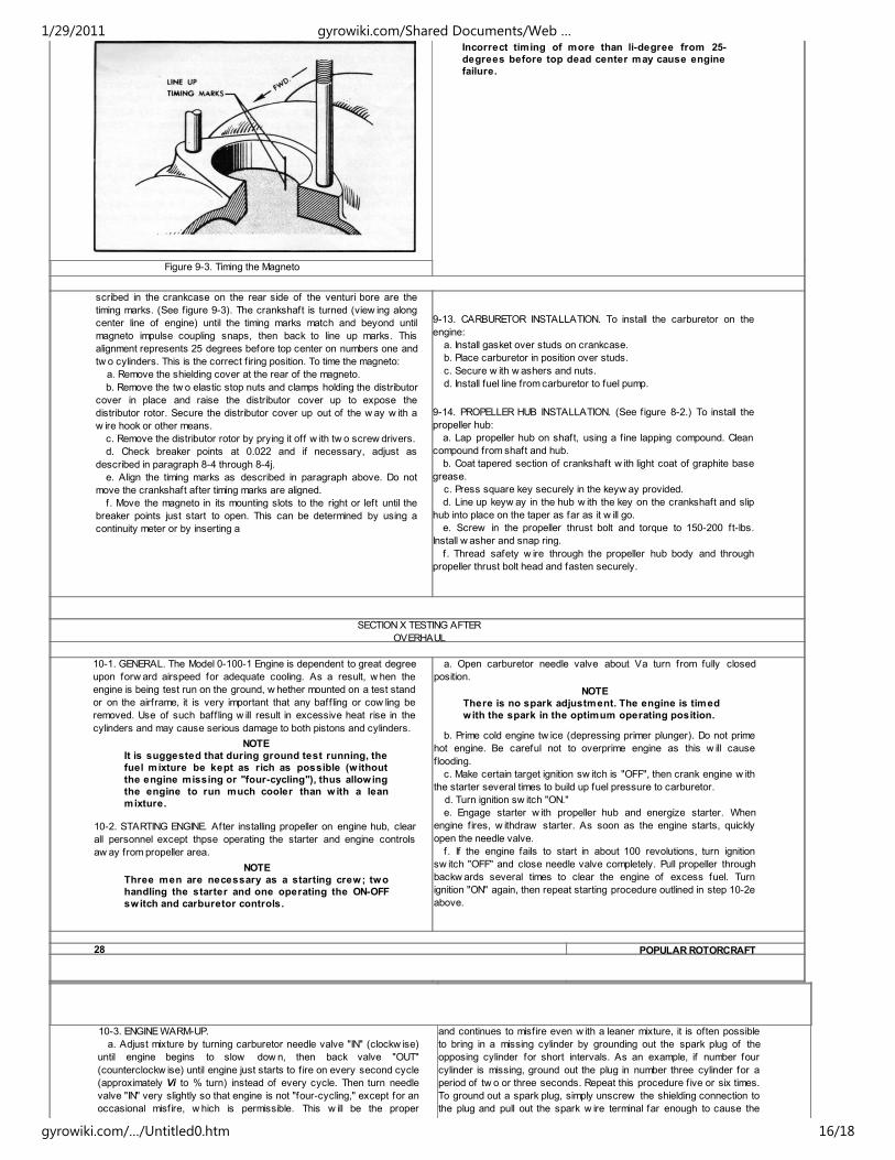
9-12. MAGNETO TIMING. A line scribed on the front face of the rear
rotary valve cheek of the crankshaft and a line
ADJUST PUMP BODY TO
OBTAIN CLEARANCE
REQUIRED -i
Figure 9-2. Adjusting Fuel Pump
DECEMBER 197527
very thin piece of cellophane or paper betw een the points w hen they
are closed. Exert a slight, but steady, pull on the paper w hile moving the
magneto. When the breaker points open, the paper w ill pull free. This
w ould be the correct timing position.
g. Torque the tw o magneto mounting nuts evenly to 13-16 ft-lbs.
w hen the magneto is in the correct timing position. Recheck timing and
readjust if necessary.
h. Replace the distributor rotor and cover and clamp securely into
position. Replace the ground w ire. Replace the cover and retainer
clamps, making sure that both are correctly seated. Secure w ith tw o
screw s.
CAUTION
1/29/2011 gyrowiki.com/Shared Documents/Web …
gyrowiki.com/…/Untitled0.htm 15/18
Incorrect timing of more than li-degree from 25-
degrees before top dead center may cause engine
failure.
Figure 9-3. Timing the Magneto
scribed in the crankcase on the rear side of the venturi bore are the
timing marks. (See figure 9-3). The crankshaft is turned (view ing along
center line of engine) until the timing marks match and beyond until
magneto impulse coupling snaps, then back to line up marks. This
alignment represents 25 degrees before top center on numbers one and
tw o cylinders. This is the correct f iring position. To time the magneto:
a. Remove the shielding cover at the rear of the magneto.
b. Remove the tw o elastic stop nuts and clamps holding the distributor
cover in place and raise the distributor cover up to expose the
distributor rotor. Secure the distributor cover up out of the w ay w ith a
w ire hook or other means.
c. Remove the distributor rotor by prying it off w ith tw o screw drivers.
d. Check breaker points at 0.022 and if necessary, adjust as
described in paragraph 8-4 through 8-4j.
e. Align the timing marks as described in paragraph above. Do not
move the crankshaft after timing marks are aligned.
f. Move the magneto in its mounting slots to the right or left until the
breaker points just start to open. This can be determined by using a
continuity meter or by inserting a
9-13. CARBURETOR INSTALLATION. To install the carburetor on the
engine:
a. Install gasket over studs on crankcase.
b. Place carburetor in position over studs.
c. Secure w ith w ashers and nuts.
d. Install fuel line from carburetor to fuel pump.
9-14. PROPELLER HUB INSTALLATION. (See f igure 8-2.) To install the
propeller hub:
a. Lap propeller hub on shaft, using a f ine lapping compound. Clean
compound from shaft and hub.
b. Coat tapered section of crankshaft w ith light coat of graphite base
grease.
c. Press square key securely in the keyw ay provided.
d. Line up keyw ay in the hub w ith the key on the crankshaft and slip
hub into place on the taper as far as it w ill go.
e. Screw in the propeller thrust bolt and torque to 150-200 ft-lbs.
Install w asher and snap ring.
f. Thread safety w ire through the propeller hub body and through
propeller thrust bolt head and fasten securely.
SECTION X TESTING AFTER
OVERHAUL
10-1. GENERAL. The Model 0-100-1 Engine is dependent to great degree
upon forw ard airspeed for adequate cooling. As a result, w hen the
engine is being test run on the ground, w hether mounted on a test stand
or on the airframe, it is very important that any baff ling or cow ling be
removed. Use of such baff ling w ill result in excessive heat rise in the
cylinders and may cause serious damage to both pistons and cylinders.
NOTE
It is suggested that during ground test running, the
fuel mixture be kept as rich as possible (w ithout
the engine missing or "four-cycling"), thus allowing
the engine to run much cooler than w ith a lean
mixture.
10-2. STARTING ENGINE. After installing propeller on engine hub, clear
all personnel except thpse operating the starter and engine controls
aw ay from propeller area.
NOTE
Three men are necessary as a starting crew; two
handling the starter and one operating the ON-OFF
switch and carburetor controls.
a. Open carburetor needle valve about Va turn from fully closed
position.
NOTE
There is no spark adjustment. The engine is timed
with the spark in the optimum operating position.
b. Prime cold engine tw ice (depressing primer plunger). Do not prime
hot engine. Be careful not to overprime engine as this w ill cause
flooding.
c. Make certain target ignition sw itch is "OFF", then crank engine w ith
the starter several times to build up fuel pressure to carburetor.
d. Turn ignition sw itch "ON."
e. Engage starter w ith propeller hub and energize starter. When
engine f ires, w ithdraw starter. As soon as the engine starts, quickly
open the needle valve.
f. If the engine fails to start in about 100 revolutions, turn ignition
sw itch "OFF" and close needle valve completely. Pull propeller through
backw ards several times to clear the engine of excess fuel. Turn
ignition "ON" again, then repeat starting procedure outlined in step 10-2e
above.
28 POPULAR ROTORCRAFT
10-3. ENGINE WARM-UP.
a. Adjust mixture by turning carburetor needle valve "IN" (clockw ise)
until engine begins to slow dow n, then back valve "OUT"
(counterclockw ise) until engine just starts to f ire on every second cycle
(approximately Vi to % turn) instead of every cycle. Then turn needle
valve "IN" very slightly so that engine is not "four-cycling," except for an
occasional misfire, w hich is permissible. This w ill be the proper
and continues to misfire even w ith a leaner mixture, it is often possible
to bring in a missing cylinder by grounding out the spark plug of the
opposing cylinder for short intervals. As an example, if number four
cylinder is missing, ground out the plug in number three cylinder for a
period of tw o or three seconds. Repeat this procedure f ive or six times.
To ground out a spark plug, simply unscrew the shielding connection to
the plug and pull out the spark w ire terminal far enough to cause the
1/29/2011 gyrowiki.com/Shared Documents/Web …
gyrowiki.com/…/Untitled0.htm 16/18
carburetor setting for ground operation.
b. Excessive misfires are primarily due to over-priming the engine.
How ever, this should be eliminated after the crew becomes more
familiar w ith both the amount of priming necessary for engine starting
and also the proper carburetor setting for engine operation.
plug to misfire. This can be done w hile the engine is running w ithout
danger of an ignition shock. Care should be taken not to keep the plug
grounded out too long at one time, otherw ise it w ill foul also. Should the
engine continue to misfire, then adjust needle valve richer again. If this
fails it w ill be necesaary to stop the engine and clean or replace the
missing spark plug. How ever, it must be remembered that the engine
may misfire due to other causes.
NOTE
It is sometimes very difficult to determine which
cylinder is missing when the engine is firing on
only three cylinders. This can most readily be done
by feeling of the cylinder fins. The coolest cylinder
is most likely the one that is misfiring or not firing.
Another method is to ground out the spark plugsas described above, one at a time in sequence. The
cylinder which fails to produce a decided drop in
engine speed while being grounded is the missing
cylinder. After engine is running smoothly, a run of
5 minutes is all that is necessary to assure that the
engine is in good order.
10-5. STOPPING THE ENGINE. To stop the engine w hile running on the
ground, turn off the ignition sw itch. If the engine is not to be used again
immediately, the carburetor air intake and the exhaust ports should be
covered.
CAUTION
If at any time sparks are observed coming from the
exhausts, it indicates an excessively hot cylinder
and a burning piston. Stop the engine immediately
and determine the cause of trouble.
10-4. CORRECTION FOR MISFIRING. If the engine continues to misfire,
adjust the fuel mixture leaner by turning the needle valve tow ard the
right or clockw ise. Leave in this position until the excess fuel is cleared
out of the engine and it runs smoothly on all four cylinders. Then
increase the fuel mixture by turning the needle valve tow ard the left or
counterclockw ise until the engine begins to miss or four-cycle because
of an excessively rich mixture. When this occurs, adjust the needle
valve leaner or back tow ard the right just enough to make the engine run
smoothly again. This should be the ideal mixture for static running on the
ground for testing or run-in purposes at w ide open throttle. If the engine
fails to clear out after starting
SECTION XI
ACCESSORIES
11-1. All accessories used on the Models 0-100-1 engine are either
manufactured by McCulloch Motors Corporation or are rew orked to meet
the requirements of these engines. No reference is made to other
service publications since all possible phases of overhaul of the entire
engine and its accessories are covered in this handbook.
DECEMBER 1975 29
SECTION X I I
TABLE OF LIMITS
12-1. INTRODUCTION. The follow ing Table of Limits gives all vital
clearance and end-play data necessary for checking and replacing
parts as described therein.
12-2. TABLE OF LIMITS.
DescriptionManufacturing
MinimumManufacturingMaximum
ReplacementMaximum
1/29/2011 gyrowiki.com/Shared Documents/Web …
gyrowiki.com/…/Untitled0.htm 17/18
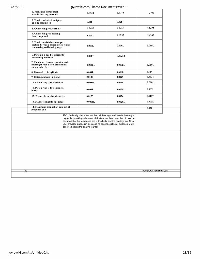
1. Front and center mainneedle bearing journals
1.3734 1.3740 1.3730
2. Total crankshaft end play,engine assembled 0.015 0.025
3. Connecting rod journals 1.2487 1.2492 1.2477
4. Connecting rod bearingbore, large end 1.6252 1.6257 1.6262
5. Total chordal clearance persection between bearing rollers andconnecting rod bearing cage
0.003L 0.006L 0.009L
6. Piston pin needle bearing toconnecting rod bore
0.001T 0.0025T
7. Total end clearance, center mainbearing thrust face to crankshaftrotary valve face
0.0055L 0.0075L 0.009L
8. Piston skirt in cylinder 0.004L 0.006L 0.009L
9. Piston pin bore in piston 0.8127 0.8129 0.8131
10. Piston ring side clearance 0.0035L 0.005L 0.010L
11. Piston ring side clearance,lower 0.001L 0.0025L 0.005L
12. Piston pin outside diameter 0.8123 0.8126 0.8117
13. Magneto shaft to bushings 0.0005L 0.0020L 0.003L
14. Maximum crankshaft run-out atpropeller end
0.020
12-3. Ordinarily the w ear on the ball bearings and needle bearing is
negligible, providing adequate lubrication has been supplied. It may be
assumed that the tolerances are w ithin limits and the bearings are f it for
use, provided inspection discloses no scoring, galling or evidence of ex�
cessive heat on the bearing journal.
30 POPULAR ROTORCRAFT
1/29/2011 gyrowiki.com/Shared Documents/Web …
gyrowiki.com/…/Untitled0.htm 18/18