Embed Size (px)
Citation preview
Control and Data Systems Division (D/TOS-ES)Keplerlaan 1 - Noordwijk - The Netherlands
Mail address: Postbus 299 - 2200 AG Noordwijk - The NetherlandsTel: +31-71-565 4722 - E-mail: [email protected] - Fax: +31-71-565 4295
european space agencyeuropean space researchand technology centre
D/TOS-ESM/SH/154Issue 0.2 December 2003
esaestec
Prepared by S. Habinc
CCSDS Unsegmented Code (CUC)&
CCSDS Time Manager (CTM)
Synthesizable VHDL Cores
Data Sheet
european space agency 2 D/TOS-ESM/SH/154 Issue 0.2
1 INTRODUCTION
This document defines the functionality of the CCSDS Unsegmented Code (CUC) and theCCSDS Time Manager (CTM) synthesizable VHDL cores.
1.1 Applicable documents
AD1 CCSDS 301.0-B-2: Recommendation: Time Code Formats, Blue Book, April 1990, www.ccsds.org
AD2 Packet Telemetry Standard, ESA PSS-04-106, Issue 1, January 1988AD3 AMBATM Specification (Rev 2.0), ARMTM IHI 0011A, 13th May 1999,
Issue A, first release, ARM Limited, www.arm.com
1.2 Applicable VHDL source code
AD4 AMBA synthesizable VHDL package, version 0.5, file amba.vhd, AD5 CCSDS Unsegmented Code (CUC) VHDL core, version 0.2, file cuc.vhdAD6 CCSDS Time Manager (CTM) VHDL core, version 0.2, file ctm.vhd
References AD4 to AD6 can be obtained from www.estec.esa.int/microelectronics
1.3 Reference documents
RD1 CCSDS 102.0-B-4: Recommendation: Packet Telemetry, Blue Book, November 1995, www.ccsds.org
RD2 ESA VHDL Modelling Guidelines, ASIC/001, Issue 1, September 1994, www.estec.esa.int/microelectronics
RD3 IEEE Standard VHDL Language Reference Manual, IEEE Std 1076-1993RD4 IEEE Standard Multivalue Logic System for VHDL Model Interoperability
(Std_Logic_1164), IEEE Std 1164-1993RD5 IEEE Standards Interpretations: IEEE Standard VHDL Language Reference
Manual, IEEE Std 1076/INT-1991
1.4 Acronyms and abbreviations
AHB Advanced High-performance BusAPB Advanced Peripheral BusAMBA Advanced Microcontroller Bus ArchitectureARM Advanced RISC MachinesCCSDS Consultative Committee for Space Data SystemsTAI Temps Atomique InternationalVHDL VHSIC Hardware Description LanguageVHSIC Very High Speed Integrated Circuits

european space agency 3 D/TOS-ESM/SH/154 Issue 0.2
2 FUNCTIONAL DESCRIPTION
2.1 Summary of operation
The CCSDS Unsegmented Code (CUC) synthesizable VHDL core provides basic timekeeping functions such an Elapsed Time (ET) counter according to the CCSDSUnsegmented Code specification, AD1. It provides support for setting, sampling andcorrelating the ET counter. It also comprises a Frequency Synthesizer (FS) with which abinary frequency is generated to drive the ET counter. It provides support for setting theincrement rate of the ET counter as well as of the FS counter.
The CCSDS Time Manager (CTM) synthesizable VHDL core provides some basic timeservices based on the ET counter implemented in the embedded CCSDS UnsegmentedCode (CUC) synthesizable VHDL core. It provides datation services that sample the ETcounter value on external events. It provides alarm services that generate an interruptwhen the ET counter value matches arbitrary alarm times. It provides an independentcounter that maintains a fine time CUC compliant counter, for the generation of periodicpulses with periods less than one second. This counter is not effected by time setting,sampling or correlation of the aforementioned ET counter. It provides also a dedicateddatation service for sampling the ET counter value on the occurrence of the time strobegenerated by the Packet TeleMetry Encoder (PTME), generating a Standard SpacecraftTime Source Packet according to the ESA Packet Telemetry Standard, AD2. All servicesin the CTM VHDL core and those comprised in the embedded CUC VHDL core areaccessible via a primary AMBA APB slave interface. All incoming events and outgoingalarms and pulses are also reported through a general interrupt signal that is handled byan interrupt manager. The Standard Spacecraft Time Source Packet is also availablethrough a secondary AMBA APB slave interface on the CTM VHDL core.
Figure 1: Simplified block diagram of the CUC and CTM cores
2.2 Description of a foreseen system using the VHDL cores
The general approach to accurately maintain onboard time is to have a central timereference measuring the elapsed time from an arbitrary epoch and to distribute regularlythis time information to onboard applications by means of messages and synchronisationpulses. Another approach would be to have a centralised time system, where each
ET Coarse ET Fine
T-FieldP-Field
PrimaryAPBslave
I/F
SecondaryAPBslave
I/F
Frequency Synthesizer
Datation
Alarm
PeriodicPulses
TimePacket
CUCCTM
RepetitiveAlarm
ET Sample

european space agency 4 D/TOS-ESM/SH/154 Issue 0.2
application that needs to time stamp data could request the unit maintaining the centraltime reference to provide the relevant time information. Such an approach would haveseveral inherent drawbacks, e.g. in systems with many users, the accuracy of a time stampcould be jeopardised due to long service latency and excessive bus traffic could degradethe overall performance of the data handling system. The purpose CUC and CTM VHDLcores is to provide a building block for such time distribution services by providing themeans for CCSDS compliant time keeping and a set of basic user time services.
Most time distribution implementations have required support from the applicationprocessor to maintain synchronisation between the central and the local time references.Protocols and formats for distributing time information have differed between spacecraftand have sometimes only provided low resolution or poor accuracy. The purpose of theCTM VHDL core is to provide an accurate time coherence throughout the spacecraft, butit does not implement the time distribution itself since this can be made in several waysdepending on e.g. usage of onboard data buses, communication protocol selection etc.
The correlation between the central time reference and ground has already been foreseenby providing a time strobe from the Packet Telemetry encoder (PTME) VHDL core. Thetime strobe has a deterministic relationship to the bit structure of the telemetry frame. Thismakes it possible to establish the time relation between the assertion of this time strobeonboard and the reception of the relevant frame on ground, taking into account the downlink propagation delay. Each CTM VHDL core instance maintains its own copy of thecentral elapsed time reference with which onboard applications can time stamp their data.This unbroken chain of time relationships onboard, and between the spacecraft andground, provides a solution to the problem of knowing when an event took place onboarda spacecraft in any given space-time frame.
The CTM VHDL core is foreseen to fit any type of spacecraft data management systemsand instruments due to its generic functionality. The core is foreseen to be used both as acentral elapsed time reference in the spacecraft data management system, as well as thelocal elapsed time reference in an instrument or other subsystem. By using standardisedAMBA APB slave interfaces, the integration of the CTM VHDL core should be simplefor most systems. The availability of a primary and secondary AMBA APB interfaceallows the user to connect the CTM VHDL core to both a primary APB controlled by e.g.a microprocessor as well as to a secondary APB controlled by e.g. an autonomous unitgenerating housekeeping telemetry packet, as shown in figure 2.
Figure 2: Block diagram of a system using the CUC and CTM VHDL cores
Housekeeping
Microprocessor
AHB/APBDecoder/Bridge
TelecommandSpacecraft
Bus
Telemetry
Primary SecondaryAPBAPB
AHB
Housekeeping APBAPB
CUC
CTM

european space agency 5 D/TOS-ESM/SH/154 Issue 0.2
2.3 Functions not included
The CCSDS Time Manager (CTM) synthesizable VHDL core does not implement aprotocol for time distribution. It does not perform automatic time synchronisationalthough accurate time correlation is possible. No time quality issues are addressed.
2.4 Data formats
All Elapsed Time information handled by the CUC and CTM VHDL cores is compliantwith the CCSDS Unsegmented Code defined in AD1 and repeated hereafter.
2.4.1 CCSDS Unsegmented Code: Preamble Field (P-Field)
The time code preamble field (P-Field) may be either explicitly or implicitly conveyed. Ifit is implicitly conveyed (not present with T-Field), the code is not self-identified, andidentification must be obtained by other means. As presently defined, the explicitrepresentation of the P-Field is limited to one octet whose format is described in table 1.
1 For the 1958 epoch, bits 4 to 5 must be set to “11” to ensure a long enoughambiguity period.
2 For the Standard Spacecraft Time Source Packet defined in the ESA PacketTelemetry Standard, bits 1 to 3 must be set to “010”. This value is howeverselectable between “001” and “010” in the CUC VHDL core.
2.4.2 CCSDS Unsegmented Code: Time Field (T-Field)
For the unsegmented binary time codes described herein, the T-Field consists of a selectednumber of contiguous time elements, each element being one octet in length. An elementrepresents the state of 8 consecutive bits of a binary counter, cascaded with the adjacentcounters, which rolls over at a modulo of 256, as shown in table 2.
Bit Value Interpretation
0 0 Extension flag
1 - 3 001 1958 January 1 epoch (Level 1) 1 Time code identification
010 Agency-defined epoch (Level 2) 2
4 - 5 (number of octets of coarse time) - 1 Detail bits for information on the code
6 - 7 (number of octets of fine time)
Table 1: CCSDS Unsegmented Code P-Field definition
CCSDS Unsegmented Code
Preamble Time Field
Field Coarse time Fine time
231 224 223 216 215 28 27 20 2-1 2-8 2-9 2-16 2-17 2-24
Table 2: CCSDS Unsegmented Code T-Field definition

european space agency 6 D/TOS-ESM/SH/154 Issue 0.2
The basic time unit is the second. The T-Field consists of 1 to 4 octets of coarse time(seconds) and 0 to 3 octets of fine time (sub seconds). The coarse time code elements area count of the number of seconds elapsed from the epoch. Four octets of coarse timeresults in a maximum ambiguity period of approximately 136 years.
This allows a time code representation of time through the year 2094 for those which arereferenced to the TAI epoch of 1958 January 1. The CCSDS-Recommended epoch is thatof 1958 January 1 (TAI), but other Agency-defined epochs may be accommodated as aLevel 2 code.
Zero to three octets of fine code elements result in a resolution of, respectively: 1 second;2-8 second (about 4 ms); 2-16 second (about 15 ms); or 2 -24 second (about 60 ns).
This time code is not UTC-based and leap second corrections do not apply.
2.5 Numbering and naming conventions
Convention according to the CCSDS recommendations, applying to time structures:• The most significant bit of an array is located to the left, carrying index number zero.• An octet comprises eight bits.
Convention according to AMBATM Specification, applying to the APB interface:• Signal names are in upper case, except for the following: • A lower case 'n' in the name indicates that the signal is active low. • Constant names are in upper case.• The least significant bit of an array is located to the right, carrying index number zero.
General convention, applying to all other signals and interfaces:• Signal names are in mixed case.• An upper case '_N' suffix in the name indicates that the signal is active low.
CCSDS n-bit field
most significant least significant
0 1 to n-2 n-1
Table 3: CCSDS n-bit field definition
AMBA n-bit field
most significant least significant
n-1 n-2 downto 1 0
Table 4: AMBA n-bit field definition

european space agency 7 D/TOS-ESM/SH/154 Issue 0.2
2.6 CCSDS Unsegmented Code (CUC)
2.6.1 General
The CCSDS Unsegmented Code (CUC) synthesizable VHDL core provides basic timekeeping functions such an Elapsed Time (ET) counter according to the CCSDSUnsegmented Code specification, AD1. It provides support for setting, sampling andcorrelating the ET counter. It also comprises a Frequency Synthesizer (FS) with which abinary frequency is generated to drive the ET counter. It provides support for setting theincrement rate of the ET counter as well as of the FS counter.
2.6.2 Elapsed Time (ET)
The local Elapsed Time (ET) counter is based on a default 32 bit coarse time field and a24 bit fine time field, complying to the CUC T-Field, AD1. The width of the two timefields can be set by means of generics, determining the number of octets for each field.The counter implementing the ET is incremented on the system clock only when enabledby the frequency synthesizer described below. The ET is incremented with aprogrammable increment value, which should match the synthesised frequency(section 2.6.3). The width of the increment input can be set by means of a generic,determining the number of bits. The local ET is output in the CUC format, P-Field and T-Field, to be used by an application embedding the CUC VHDL core, e.g. the CTM VHDLcore. The P-Field is automatically derived from the generics. The Time Code Identifiercan be set to either “001” or “010”, being run time selectable.
2.6.3 Frequency Synthesizer (FS)
The binary frequency required to determine the ET counter increment is derived from thesystem clock using a default 24 bit frequency synthesizer. The width of the frequencysynthesizer can be set by means of a generic, determining the number of bits. Thefrequency synthesizer is incremented with a programmable increment value, whichshould match the available system clock frequency. The output of the frequencysynthesizer is used for enabling the increment of the local ET as described above, as wellas for driving other counters implemented by applications embedding the CUC core.
2.6.4 Time setting and correlation
It is possible to set the local ET counter with an input value. The format of the input is theCUC T-Field. It is possible to reset the phase in the frequency synthesizer. It is possibleto sample the local ET counter value. This register is primarily be used for the purpose oftime correlation. The implementation of the register can be enabled or disabled by meansof a generic. The format of the output is the CUC T-Field. It is possible to correlate aninput reference time value with the sampled ET value and the current local ET countervalue. This is done by calculating the difference between the input reference time valuewith the sampled ET value and subtract or add the difference to the current local ETcounter value. The implementation of the correlation can be enabled or disabled by meansof a generic. The data format is the CUC T-Field.
european space agency 8 D/TOS-ESM/SH/154 Issue 0.2
2.6.5 Programmable registers, state after reset and error handling
There are not programmable registers. The only registers are the ET and FS counters, andthe sample register. All registers are cleared at reset. There is only one operational mode.The core is fully synchronous. There is no explicit error handling. For configuration of theET and FS counters, see section 2.6.6.
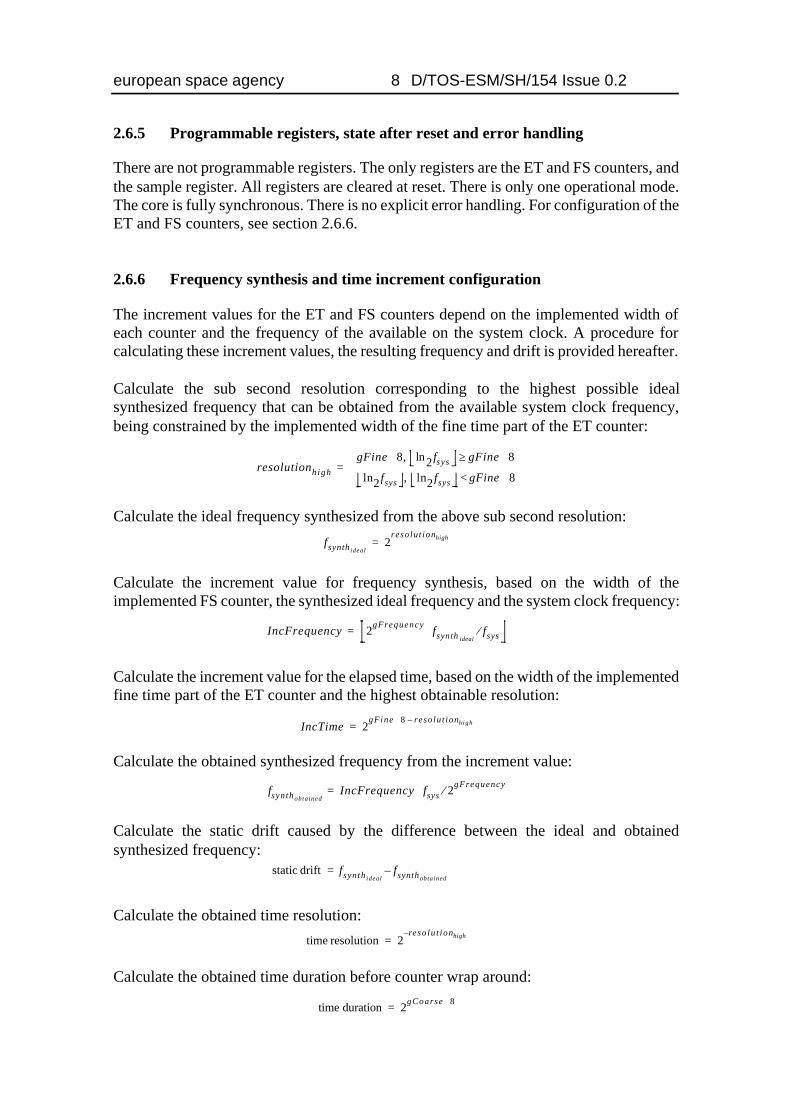
2.6.6 Frequency synthesis and time increment configuration
The increment values for the ET and FS counters depend on the implemented width ofeach counter and the frequency of the available on the system clock. A procedure forcalculating these increment values, the resulting frequency and drift is provided hereafter.
Calculate the sub second resolution corresponding to the highest possible idealsynthesized frequency that can be obtained from the available system clock frequency,being constrained by the implemented width of the fine time part of the ET counter:
Calculate the ideal frequency synthesized from the above sub second resolution:
Calculate the increment value for frequency synthesis, based on the width of theimplemented FS counter, the synthesized ideal frequency and the system clock frequency:
Calculate the increment value for the elapsed time, based on the width of the implementedfine time part of the ET counter and the highest obtainable resolution:
Calculate the obtained synthesized frequency from the increment value:
Calculate the static drift caused by the difference between the ideal and obtainedsynthesized frequency:
Calculate the obtained time resolution:
Calculate the obtained time duration before counter wrap around:
resolutionhigh
gFine 8⋅ 2ln fsys gFine 8⋅≥,
2ln fsys 2ln fsys gFine 8⋅<,
=
fsynthideal2
reso lu t ionhigh=
IncFrequency 2gFrequency fsynth idealfsys⁄⋅=
IncTime 2gFine 8⋅ reso lu t ionhigh–
=
fsynthobta inedIncFrequency fsys 2gFrequency⁄⋅=
static drift fsynth idealfsynthobtained
–=
time resolution 2r– eso lu t ionhigh=
time duration 2gCoarse 8⋅=
european space agency 9 D/TOS-ESM/SH/154 Issue 0.2
2.7 CCSDS Time Manager (CTM)
2.7.1 General
The CCSDS Time Manager (CTM) synthesizable VHDL core is compliant with theCCSDS Unsegmented Code format, AD1. It embeds the CCSDS Unsegmented Code(CUC) synthesizable VHDL core.
In addition to the functions embedded in the CUC VHDL core, the CTM VHDL coreprovides datation, alarm, repetitive alarm, fixed pulses and programmable periodicpulses, as well as generates a Standard Spacecraft Time Source Packet according to AD2.The width and format of all registers are configurable via a subset of generics as availablefor the CUC VHDL core.
The interfaces to the CTM core are based on two independent AMBA APB slaveinterfaces, according to AD3.
2.7.2 Interfaces
The CTM comprises two independent AMBA APB slave interfaces: a primary interfacefor general access to all resources and services; and a secondary interface limited to theread-out of the Standard Spacecraft Time Source Packet. The only common signals arethe AMBA APB clock and reset. The address inputs of the APB slave interfaces areincompletely decoded. All time services, including the Elapsed Time counter in theembedded CUC VHDL core, are clocked by the AMBA APB clock PCLK.
There are four external event input signal that can be used with the datation registers, asdescribed in section 2.7.3. They can also be used with the Standard Spacecraft TimeSource Packet register described in section 2.7.8, and for the time setting and correlation,and frequency synthesizer reset as described in section 2.6.
There are two external alarm outputs that are used for the alarm and the repetitive alarmgeneration described in section 2.7.4 and section 2.7.5. Note that the alarm outputs areasserted one APB clock period after the corresponding increment of the ET counterembedded in the CUC VHDL core.
There is an output that is asserted once every second, as described in section 2.7.6. Thereis an output that is asserted every time the frequency synthesizer counter wraps around,as described in section 2.7.6. There are four external pulse outputs that are used for theperiodic pulse generation described in section 2.7.7.
There is one interrupt output that is used for reporting all incoming events, and outgoingalarms and pulses, which is handled by the interrupt manager described in section 2.7.9.
All input signals are assumed to be synchronous with the AMBA APB interface clockPCLK. No input signal synchronisation is performed in the core. All outputs aresynchronous with the AMBA APB interface clock, except when explicitly stated insection 3.2.
european space agency 10 D/TOS-ESM/SH/154 Issue 0.2
2.7.3 Datation
The CTM VHDL core comprises two datation registers for the purpose of datation of userevents relative the ET counter in the embedded CUC VHDL core. These two registers areprovided in addition to the ET sample register in the embed CUC VHDL core, which isprimarily used for time correlation etc. A fourth datation register is provided for samplingthe ET counter when generating a Standard Spacecraft Time Source Packet as describedin section 2.7.8.
For all four registers, it is possible to sample the ET counter on an external event or via aregister access. For each register it is possible to independently select the source that willtrigger the sample. It can either be one of the four external event signals or by registeraccess via the primary AMBA APB slave interface. It is possible to enable or disable theoccurrence of a sample by via the aforementioned interface. Each datation service isautomatically disabled after an occurrence. The format of all four registers is compliantto the CUC T-Field. The fourth datation register is also accessible via the secondary APBslave interface as described in section 2.7.8.
2.7.4 Alarm
The CTM VHDL core comprises one alarm that is generated relative the ET counter inthe embedded CUC VHDL core. The alarm is generated on the Alarms(0) output. Thetime on which the alarm will be generated is programmable via the primary AMBA APBslave interface. It is possible to enable or disable the occurrence of an alarm via theaforementioned interface. The alarm is automatically disabled after an occurrence. Thewidth of the alarm output pulse is one AMBA APB clock period. Note that the alarmoutput is asserted one APB clock PCLK period after the corresponding increment of theET counter embedded in the CUC VHDL core. The format of the alarm time is compliantto the CUC T-Field.
2.7.5 Repetitive alarm
The CTM VHDL core comprises one periodically repeated alarm that is generatedrelative the ET counter in the embedded CUC VHDL core. The repetitive alarm isgenerated on the Alarms(1) output. The width of the repetitive alarm output pulse is oneAMBA APB clock period. Note that the repetitive alarm output is asserted one APB clockPCLK period after the corresponding increment of the ET counter embedded in the CUCVHDL core.
The time on which the alarm will be generated is programmable via the primary AMBAAPB slave interface. It is possible to mask an arbitrary number of bits when performingcomparison between the local ET and the alarm time, resulting in a periodically generatedalarm output. It is possible to enable or disable the occurrence of an alarm via theaforementioned interface. The format of the alarm time and the mask is compliant to theCUC T-Field. Bits that are set to logical zero in the mask are excluded in the comparison.

european space agency 11 D/TOS-ESM/SH/154 Issue 0.2
2.7.6 Fixed pulses
The CTM VHDL core comprises two fixed period pulses that are propagated from theCUC VHDL core. The Seconds(0) output is asserted when the Frequency Synthesizercounter is wrapped around. The Seconds(1) output is asserted when the ET counter onesecond bit position is incremented. The width of the output pulses is one AMBA APBclock PCLK period. It is possible to enable or disable individually the occurrence of thepulse outputs via the primary AMBA APB slave interface.
2.7.7 Periodic pulses
The CTM VHDL core provides support for generating periodic pulses on four outputsderived from a dedicated CUC fine time counter. The counter can be reset independentlyfrom the CUC ET counter, providing a constant frequency. The counter is driven by theFrequency Synthesizer that is embedded in the CUC core. The time increment is the sameas for the CUC ET counter. The periodic pulses are generated on the Pulses(0:3) outputs.The width of the periodic output pulses is one AMBA APB clock PCLK period. Thefrequencies on which the pulses will be generated are programmable as masks via theprimary AMBA APB slave interface. The format of the mask is compliant to the fine timepart of the CUC T-Field. Bits that are set to logical zero in the mask are excluded in thecomparison with the counter all zero value. It is possible to enable or disable individuallythe occurrence of the periodic pulse outputs via the aforementioned interface.
2.7.8 Standard Spacecraft Time Source Packet
The CTM VHDL core comprises one datation register for sampling the ET counter whengenerating a Standard Spacecraft Time Source Packet according to the ESA PacketTelemetry Standard, AD2. It is possible to sample the ET counter on an external event orvia a register access. It is possible to select the source that will trigger the sample. It caneither be one of the four external event signals, or by register access via the primaryAMBA APB slave interface. It is possible to enable or disable the occurrence of a samplevia the aforementioned interface. This datation register can be accessed via the primaryAPB slave interface and the format is compliant to the CUC T-Field. This datation registercan also be accessed via the secondary APB slave interface. The format then complies toeither the CUC T-Field or to the Standard Spacecraft Time Source Packet formatdescribed in AD2. The selection is made by means of a generic. In case the latter isselected, a Source Sequence Count is implemented as well, see table 10.
2.7.9 Interrupt manager
The CTM VHDL core comprises an interrupt manager that combines the discrete alarmand pulse outputs described above, and the discrete event inputs into a single interruptoutput Interrupt. Each interrupt source can be individually masked, cleared and set. Theinterrupt output is asserted until all pending interrupt sources have been cleared. Allaccesses to the interrupt manager are via the primary AMBA APB slave interface.

european space agency 12 D/TOS-ESM/SH/154 Issue 0.2
2.7.10 Programmable registers and operational modes
The primary CTM AMBA APB slave interface supports 32 bit wide data input and output.The input address is interpreted as a byte address, as per AD4. Since each access is a wordaccess, the two least significant address bits are assumed always to be zero, only addressbits 6:2 are decoded. Misaligned addressing is not supported. For read accesses, dataoutput is produced combinatorially from address etc., un-mapped bits are always drivento zero, is designed to work in a multiplexed unidirectional bus scheme. Re-mappingbetween the opposing numbering conventions in the CCSDS and AMBA documentationis performed. When the CCSDS field is narrower than the AMBA data width, zeros arepadded to the left. The primary AMBA APB slave interface provides direct access to theP-Field and T-Field of the ET counter embedded in the CUC VHDL core. It should benoted that the T-Field counter value is not frozen during read out and that it can changebetween reading the coarse and the fine time registers.
Register name Address Read/Write Remarks
Configuration Register 00h R/W See table6
Service Register 04h R/W See table7
Increment Frequency Register 08h R/W See section3.1.1.3
Increment Time Register 0Ch R/W See section3.1.1.4
Set/Correlate Time Coarse Register 10h R/W T-Field, coarse part
Set/Correlate Time Fine Register 14h R/W T-Field, fine part
Sample Time Coarse Register 18h R T-Field, coarse part
Sample Time Fine Register 1Ch R T-Field, fine part
Datation Coarse 0 Register 20h R T-Field, coarse part
Datation Fine 0 Register 24h R T-Field, fine part
Datation Coarse 1 Register 28h R T-Field, coarse part
Datation Fine 1 Register 2Ch R T-Field, fine part
Alarm Coarse Register 30h R/W T-Field, coarse part
Alarm Fine Register 34h R/W T-Field, fine part
Repetitive Alarm Coarse Register 38h R/W T-Field, coarse part
Repetitive Alarm Fine Register 3Ch R/W T-Field, fine part
Repetitive Alarm Coarse Mask Register 40h R/W T-Field, coarse part
Repetitive Alarm Fine Mask Register 44h R/W T-Field, fine part
Periodic Pulse Fine 0 Mask Register 48h R/W T-Field, fine part
Periodic Pulse Fine 1 Mask Register 4Ch R/W T-Field, fine part
Periodic Pulse Fine 2 Mask Register 50h R/W T-Field, fine part
Periodic Pulse Fine 3 Mask Register 54h R/W T-Field, fine part
Time Packet Coarse Register 58h R T-Field, coarse part
Time Packet Fine Register 5Ch R T-Field, fine part
Interrupt Manager Register 60h R/W See table10
CUC P-Field Register 64h R See table1
CUC T-Field Coarse Register 68h R T-Field, coarse part
CUC T-Field Fine Register 6Ch R T-Field, fine part
Unused addresses 70h:7Ch R All zeros
Table 5: CTM VHDL core registers on primary AMBA APB slave interface
european space agency 13 D/TOS-ESM/SH/154 Issue 0.2
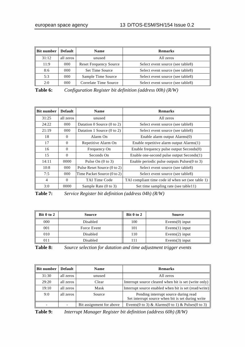
Bit number Default Name Remarks
31:12 all zeros unused All zeros
11:9 000 Reset Frequency Source Select event source (see table8)
8:6 000 Set Time Source Select event source (see table8)
5:3 000 Sample Time Source Select event source (see table8)
2:0 000 Correlate Time Source Select event source (see table8)
Table 6: Configuration Register bit definition (address 00h) (R/W)
Bit number Default Name Remarks
31:25 all zeros unused All zeros
24:22 000 Datation 0 Source (0 to 2) Select event source (see table8)
21:19 000 Datation 1 Source (0 to 2) Select event source (see table8)
18 0 Alarm On Enable alarm output Alarms(0)
17 0 Repetitive Alarm On Enable repetitive alarm output Alarms(1)
16 0 Frequency On Enable frequency pulse output Seconds(0)
15 0 Seconds On Enable one-second pulse output Seconds(1)
14:11 0000 Pulse On (0 to 3) Enable periodic pulse outputs Pulses(0 to 3)
10:8 000 Pulse Reset Source (0 to 2) Select event source (see table8)
7:5 000 Time Packet Source (0 to 2) Select event source (see table8)
4 0 TAI Time Code TAI compliant time code id when set (see table 1)
3:0 0000 Sample Rate (0 to 3) Set time sampling rate (see table11)
Table 7: Service Register bit definition (address 04h) (R/W)
Bit 0 to 2 Source Bit 0 to 2 Source
000 Disabled 100 Events(0) input
001 Force Event 101 Events(1) input
010 Disabled 110 Events(2) input
011 Disabled 111 Events(3) input
Table 8: Source selection for datation and time adjustment trigger events
Bit number Default Name Remarks
31:30 all zeros unused All zeros
29:20 all zeros Clear Interrupt source cleared when bit is set (write only)
19:10 all zeros Mask Interrupt source enabled when bit is set (read/write)
9:0 all zeros Source Pending interrupt source during read Set interrupt source when bit is set during write
- - Bit assignment for above Events(0 to 3) & Alarms(0 to 1) & Pulses(0 to 3)
Table 9: Interrupt Manager Register bit definition (address 60h) (R/W)
european space agency 14 D/TOS-ESM/SH/154 Issue 0.2
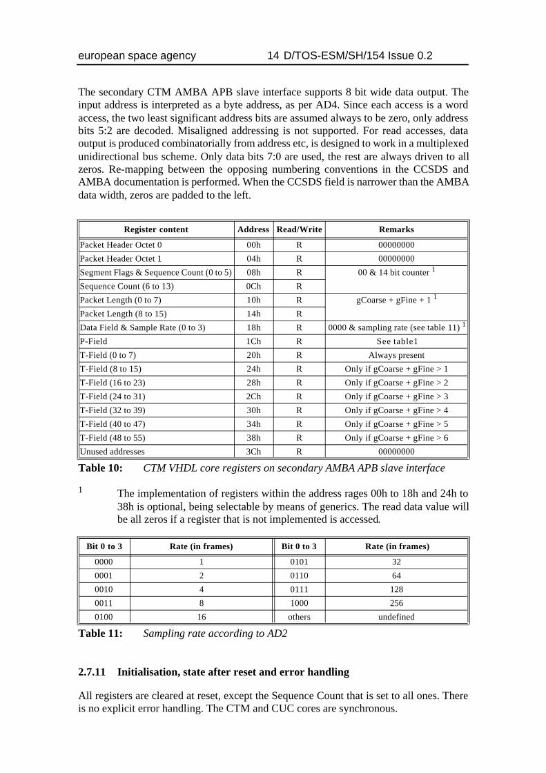
The secondary CTM AMBA APB slave interface supports 8 bit wide data output. Theinput address is interpreted as a byte address, as per AD4. Since each access is a wordaccess, the two least significant address bits are assumed always to be zero, only addressbits 5:2 are decoded. Misaligned addressing is not supported. For read accesses, dataoutput is produced combinatorially from address etc, is designed to work in a multiplexedunidirectional bus scheme. Only data bits 7:0 are used, the rest are always driven to allzeros. Re-mapping between the opposing numbering conventions in the CCSDS andAMBA documentation is performed. When the CCSDS field is narrower than the AMBAdata width, zeros are padded to the left.
1 The implementation of registers within the address rages 00h to 18h and 24h to38h is optional, being selectable by means of generics. The read data value willbe all zeros if a register that is not implemented is accessed.
2.7.11 Initialisation, state after reset and error handling
All registers are cleared at reset, except the Sequence Count that is set to all ones. Thereis no explicit error handling. The CTM and CUC cores are synchronous.
Register content Address Read/Write Remarks
Packet Header Octet 0 00h R 00000000
Packet Header Octet 1 04h R 00000000
Segment Flags & Sequence Count (0 to 5) 08h R 00 & 14 bit counter 1
Sequence Count (6 to 13) 0Ch R
Packet Length (0 to 7) 10h R gCoarse + gFine + 1 1
Packet Length (8 to 15) 14h R
Data Field & Sample Rate (0 to 3) 18h R 0000 & sampling rate (see table 11) 1
P-Field 1Ch R See table1
T-Field (0 to 7) 20h R Always present
T-Field (8 to 15) 24h R Only if gCoarse + gFine > 1
T-Field (16 to 23) 28h R Only if gCoarse + gFine > 2
T-Field (24 to 31) 2Ch R Only if gCoarse + gFine > 3
T-Field (32 to 39) 30h R Only if gCoarse + gFine > 4
T-Field (40 to 47) 34h R Only if gCoarse + gFine > 5
T-Field (48 to 55) 38h R Only if gCoarse + gFine > 6
Unused addresses 3Ch R 00000000
Table 10: CTM VHDL core registers on secondary AMBA APB slave interface
Bit 0 to 3 Rate (in frames) Bit 0 to 3 Rate (in frames)
0000 1 0101 32
0001 2 0110 64
0010 4 0111 128
0011 8 1000 256
0100 16 others undefined
Table 11: Sampling rate according to AD2
european space agency 15 D/TOS-ESM/SH/154 Issue 0.2
3 INTERFACE DESCRIPTION
3.1 CCSDS Unsegmented Code (CUC) interfaces
3.1.1 Synthesis configuration
3.1.1.1 gCoarse: Number of coarse time octets Natural range 1 to 4
This generic selects the number of octets to be implemented for the coarse time of the ET.
3.1.1.2 gFine: Number of fine time octets: Natural range 0 to 3
This generic selects the number of octets to be implemented for the fine time of the ET.
3.1.1.3 gFrequency: Width of frequency synthesizer: Positive
This generic selects the number of bits to be implemented for the frequency synthesizer.It defines the array width in bits for the frequency increment value input.
3.1.1.4 gIncrement: Width of time increment: Positive
This generic defines the array width in bits for the time increment value input. Should beequal to or less than (gCoarse + gFine) * 8 and 32, depending on the smallest value.
3.1.1.5 gSample: Time sample register support: Natural range 0 to 1
This generic selects whether a time sample register is to be implemented or not.
3.1.1.6 gCorrelate: Time correlation support: Natural range 0 to 1
This generic selects whether a time correlation is to be implemented or not. This requiresthat the time sample register is implemented.
3.1.2 System interface
3.1.2.1 Reset_rise_N: Synchronised reset: Std_ULogic (I)
This active low input signal asynchronously resets the CUC VHDL core. The signal isassumed to be synchronous with the system clock Clk rising edge. The input is used onregisters that are all clocked on the rising Clk edge.
3.1.2.2 Clk: System clock: Std_ULogic (I)
This input signal is the system clock signal for the CUC VHDL core. All registers areclocked on the rising Clk edge.
european space agency 16 D/TOS-ESM/SH/154 Issue 0.2
3.1.3 Configuration interface
3.1.3.1 TimeCodeTAI: TAI Time Code Identifier: Std_ULogic (I)
This input signal selects the Time Code Identifier in the P-Field to be compliant with theTAI format when set, i.e. “001”, else it is “010” which is compliant to AD2. The input ispassed through combinatorial logic before being sampled on rising Clk edge.
3.1.3.2 IncFrequency: Increment frequency: UnSigned(0 to gFrequency-1) (I)
This input signal sets the increment of the Frequency Synthesizer counter. The mostsignificant bit is to the left. The input is passed through combinatorial logic before beingsampled on rising Clk edge.
3.1.3.3 IncTime: Increment time: UnSigned(0 to gIncrement-1) (I)
This input signal sets the increment of the Elapsed Time counter. The most significant bitis to the left. The input is passed through combinatorial logic before being sampled onrising Clk edge.
3.1.4 Unused outputs (to guide synthesis tools during optimization)
3.1.4.1 FreqAdder: UnSigned(0 to gFrequency) (I/O)
Frequency Synthesizer counter increment adder. This is a combinatorial output.
3.1.4.2 TimeAdder: UnSigned(0 to (gCoarse+gFine)*8-1) (I/O)
Elapsed Time counter increment adder. This is a combinatorial output.
3.1.4.3 TimeCorr: UnSigned(0 to (gCoarse+gFine)*8-1) (I/O)
Elapsed Time correlation adder. This is a combinatorial output.
3.1.5 Elapsed Time counter represented as CUC
3.1.5.1 P_Field: CUC P-Field: UnSigned(0 to 7) (O)
This output signal carries the value of the P-Field. Data is output on rising Clk edge.
3.1.5.2 T_Field: CUC T-Field: UnSigned(0 to (gCoarse+gFine)*8-1)) (O)
This output signal carries the value of the ET counter T-Field. The most significant bit isto the left. Data is output on rising Clk edge.
european space agency 17 D/TOS-ESM/SH/154 Issue 0.2
3.1.6 Time set interface
3.1.6.1 ResetFreq: Reset frequency: Std_ULogic (I)
This input signal synchronously resets the Frequency Synthesizer counter when asserted.The reset of the Frequency Synthesizer corresponds to resetting the phase of the ElapsedTime counter. The input is sampled on rising Clk edge.
3.1.6.2 SetTime: Set time: Std_ULogic (I)
This input signal synchronously sets the Elapsed Time counter with the TimeInput valuewhen asserted. The input is sampled on rising Clk edge.
3.1.6.3 SampleTime: Sample time: Std_ULogic (I)
This input signal synchronously samples the Elapsed Time counter value into the timesample register when asserted. The input is sampled on rising Clk edge.
3.1.6.4 CorrelateTime: Correlate time: Std_ULogic (I)
This input signal synchronously correlates the Elapsed Time counter value that is held inthe time sample register with that value input on the TimeInput signal, and stores the resultback into the ET counter. The input is sampled on rising Clk edge.
3.1.6.5 TimeInput: Time input: UnSigned(0 to (gCoarse+gFine)*8-1) (I)
This input signal is used for setting and correlating the Elapsed Time counter. The mostsignificant bit is to the left. The input is sampled on rising Clk edge.
3.1.6.6 TimeOutput: Time output: UnSigned(0 to (gCoarse+gFine)*8-1) (O)
This output signal carries the value of the time sample register. The most significant bit isto the left. Data is output on rising Clk edge.
3.1.6.7 FreqPulse: Frequency wrap: Std_ULogic (O)
This output signal is asserted for one Clk period when the Frequency Synthesizer counteris wrapped around. The signal is output on rising Clk edge.
3.1.6.8 SecondPulse: One second period: Std_ULogic (O)
This output signal is asserted for one Clk period when the ET counter one second bitposition is incremented. The signal is output on rising Clk edge.
3.1.7 Diagnostic support
3.1.7.1 Frequency: System frequency: Natural (I)
This input signal is the system frequency that is used for diagnostics only.

european space agency 18 D/TOS-ESM/SH/154 Issue 0.2
3.2 CCSDS Time Manager (CTM) interfaces
3.2.1 Synthesis configuration
3.2.1.1 gCoarse: Number of coarse time octets Natural range 1 to 4
This generic selects the number of octets to be implemented for the coarse time of the ET.
3.2.1.2 gFine: Number of fine time octets: Natural range 1 to 3
This generic selects the number of octets to be implemented for the fine time of the ET.
3.2.1.3 gFrequency: Width of frequency synthesizer: Natural range 1 to 32
This generic selects the number of bits to be implemented for the frequency synthesizer.
3.2.1.4 gIncrement: Width of time increment: Natural range 1 to 32
This generic defines the array width in bits for the time increment value input. Should beequal to or less than (gCoarse + gFine) * 8 and 32, depending on the smallest value.
3.2.1.5 gTimeSourcePkt: Time Source Packet support: Natural range 0 to 1
This generic selects whether the Standard Spacecraft Time Source Packet support is to beimplemented or not. It effects the secondary AMBA APB slave interface only.
3.2.2 Diagnostic support
3.2.2.1 Frequency: System frequency: Natural (I)
This input signal is the system frequency that is used for diagnostics only in the CUC.
3.2.3 AMBA APB slave interface: system signals
For detailed information on the two first signals see AD3 and AD4.
3.2.3.1 PRESETn: Synchronised reset: Std_ULogic (I)
This active low input signal asynchronously resets the CTM VHDL core and theembedded CUC VHDL core. The signal is assumed to be synchronous with the AMBAAPB clock PCLK rising edge. The input is used on registers that are all clocked on therising PCLK edge.
3.2.3.2 PCLK: Interface clock: Std_ULogic (I)
This input signal is the AMBA APB clock which is the clock for the CTM VHDL coreand the embedded CUC VHDL core. All registers are clocked on the rising PCLK edge.
european space agency 19 D/TOS-ESM/SH/154 Issue 0.2
3.2.4 Primary AMBA APB slave interface
For detailed information on the records used for the APB interface see AD3 and AD4.
3.2.4.1 APBIn: Interface input: APB_Slv_In_Type (I)
This signal record is the general APB slave interface input.
3.2.4.1.1 PSEL: Slave select: Std_ULogic (I)
This signal indicates that the APB slave device is selected and a data transfer is required.The input is sampled on the rising PCLK edge for write accesses.
3.2.4.1.2 PENABLE: Enable strobe: Std_ULogic (I)
This strobe signal is used to time all accesses on the peripheral bus. The enable signal isused to indicate the second cycle of an APB transfer. The rising edge of PENABLEoccurs in the middle of the APB transfer. The input is sampled on the rising PCLK edgefor write accesses.
3.2.4.1.3 PADDR: Address bus: Std_Logic_Vector(PAMAX-1 downto 0) (I)
This is the APB address bus can be up to 32 bits wide. Only address bits 6:2 are decoded.The input is sampled on the rising PCLK edge for write accesses. PAMAX is defined inthe AMBA VHDL package, AD4.
3.2.4.1.4 PWRITE: Write strobe: Std_ULogic (I)
This signal indicates the APB transfer direction When asserted this signal indicates anAPB write access and when de-asserted a read access. The input is sampled on the risingPCLK edge for write accesses.
3.2.4.1.5 PWDATA: Write data bus: Std_Logic_Vector(PDMAX-1 downto 0) (I)
The APB write data bus is driven by the peripheral bus master during write cycles (whenPWRITE is asserted). The write data bus can be up to 32-bits wide. The data is sampledon the rising PCLK edge for write accesses. PDMAX is defined in the AMBA VHDLpackage, AD4.
3.2.4.2 APBOut: Interface output: APB_Slv_Out_Type (O)
This signal record is the general APB slave interface output.
3.2.4.2.1 PRDATA: Read data bus: Std_Logic_Vector(PDMAX-1 downto 0) (O)
The APB read data bus is driven by the selected slave during read cycles (when PWRITEis de-asserted). The read data bus can be up to 32-bits wide. The data output is producedcombinatorially from the address bus etc. PDMAX is defined in the AMBA VHDLpackage, AD4.
european space agency 20 D/TOS-ESM/SH/154 Issue 0.2
3.2.5 Secondary AMBA APB slave interface
For detailed information on the records used for the APB interface see AD3 and AD4.
3.2.5.1 APBPktIn: Interface input: APB_Slv_In_Type (I)
This signal record is the general APB slave interface input. For details on record memberssee section 3.2.4.1, with the additions listed below.
3.2.5.1.1 PADDR: Address bus: Std_Logic_Vector(PAMAX-1 downto 0) (I)
Only address bits 5:2 are decoded.
3.2.5.2 APBPktOut: Interface output: APB_Slv_Out_Type (O)
This signal record is the general APB slave interface output. For details on recordmembers see section 3.2.4.2, with the additions listed below.
3.2.5.2.1 PRDATA: Read data bus: Std_Logic_Vector(PDMAX-1 downto 0) (O)
Only data bits 7:0 are used, the rest are always driven to all zeros.
3.2.6 Time events
3.2.6.1 Events: Event input: Std_Logic_Vector(0 to 3) (I)
These inputs signal external events to which setting, sampling and correlation of time andgeneral datation can be coupled. The inputs are sampled on the rising PCLK edge.
3.2.6.2 Alarms: Alarm and repetitive alarm output: Std_Logic_Vector(0 to 1) (O)
These outputs signal the occurrence of an alarm. The generate pulse has the width of onePCLK period. The outputs are driven on the rising PCLK edge.
3.2.6.3 Seconds: Fixed periodic pulse output: Std_ULogic (O)
These output signals carry fixed periodic pulses. The generate pulse has the width of onePCLK period. The outputs are driven on the rising PCLK edge.
3.2.6.4 Pulses: Periodic pulse output: Std_Logic_Vector(0 to 3) (O)
These output signals carry periodic pulses. The generate pulse has the width of one PCLKperiod. The outputs are driven on the rising PCLK edge.
3.2.6.5 Interrupt: General interrupt output: Std_ULogic (O)
This output signal is the general interrupt signal from the CTM VHDL core. It is asserteduntil all pending sources are cleared. The output is driven on the rising PCLK edge.
european space agency 21 D/TOS-ESM/SH/154 Issue 0.2
4 VHDL SOURCE CODE DESCRIPTION
The CUC and CTM Synthesizable VHDL cores and test benches are written according toRD2 as far as applicable. The VHDL code complies to VHDL’93, RD3.
4.1 Packages and libraries, interface port and generic types
The following VHDL packages are used in the CUC VHDL core:• Std.Standard, Std.TextIO• IEEE.Std_Logic_1164, IEEE.Std_Logic_Arith, IEEE.Std_Logic_TextIO
The CUC VHDL core interfaces do not comply to the normally recommendedStd_ULogic and Std_Logic_Vector types, RD5, since the UnSigned type is used for allarrays. The generics used are not of type Integer, normally supported by synthesis tools,but are based on subtypes of Integer such as Natural and Positive.
The following VHDL packages are used in the CTM VHDL core:• Std.Standard• IEEE.Std_Logic_1164, IEEE.Std_Logic_Arith• AMBA_Lib.AMBA
The CTM VHDL core interfaces do comply to the normally required, Std_ULogic andStd_Logic_Vector types, RD2. The generics used are not of type Integer, normallysupported by synthesis tools, but are based on subtypes of Integer such as Natural andPositive.
The recommended target library for the CUC and CTM VHDL cores is CUC_Lib. Notethat the they can be located in another library than CUC_Lib, but this will require amodification of one line in the CTM VHDL code.
Note that the AMBA interface can be located in another library than AMBA_Lib, but thiswill also require a modification of one line in the CTM VHDL code.
4.2 Special considerations
The CUC VHDL core provides diagnostic support by means of writing information to thestandard output when one of the input settings is modified. The information is derivedfrom the diagnostic input signal specifying the real time frequency of the system clockused by the core. The provided information comprises CUC P-Field reporting andfrequency and time accuracy reporting. The minimum width of the ET counter is assertedwhen the Time Code Identifier is set to TAI compliance.
The CUC VHDL core interface has three input/output signals that are used for guidingsome synthesis tools during optimization. These signals are all related to different addersin the core and should remain unconnected.
Page intentionally left blank
Copyright © 2000 European Space Agency. All rights reserved.All rights reserved. This document may be used and distributed without restrictions provided that thiscopyright statement is retained and that any derivative work acknowledges the origin of the information.
european space agency 22 D/TOS-ESM/SH/154 Issue 0.2


![WSD/JG/426 Issue 1 December 1997 Original: Englishmicroelectronics.esa.int/core/ipdoc/EVI32.pdf · • single level arbiter (sgl); • vme bus timer; ... virqout[3:0] iackin iackout](https://img.pdfslide.us/doc/110x75/5b92655509d3f215288dd3cb/wsdjg426-issue-1-december-1997-original-eng-single-level-arbiter-sgl.jpg)