Embed Size (px)
Citation preview

Report Concerning Space Data System Standards
MISSION OPERATIONS SERVICES CONCEPT
INFORMATIONAL REPORT
CCSDS 520.0-G-3
GREEN BOOK December 2010
Report Concerning Space Data System Standards
MISSION OPERATIONS SERVICES CONCEPT
INFORMATIONAL REPORT
CCSDS 520.0-G-3
GREEN BOOK December 2010

CCSDS REPORT CONCERNING MISSION OPERATIONS SERVICES CONCEPT
AUTHORITY
Issue: Informational Report, Issue 3
Date: December 2010
Location: Washington, DC, USA
This document has been approved for publication by the Management Council of the Consultative Committee for Space Data Systems (CCSDS) and reflects the consensus of technical panel experts from CCSDS Member Agencies. The procedure for review and authorization of CCSDS Reports is detailed in the Procedures Manual for the Consultative Committee for Space Data Systems.
This document is published and maintained by:
CCSDS Secretariat Space Communications and Navigation Office, 7L70 Space Operations Mission Directorate NASA Headquarters Washington, DC 20546-0001, USA
CCSDS 520.0-G-3 Page i December 2010

CCSDS REPORT CONCERNING MISSION OPERATIONS SERVICES CONCEPT
FOREWORD
Through the process of normal evolution, it is expected that expansion, deletion, or modification of this document may occur. This Report is therefore subject to CCSDS document management and change control procedures, which are defined in the Procedures Manual for the Consultative Committee for Space Data Systems. Current versions of CCSDS documents are maintained at the CCSDS Web site:
http://www.ccsds.org/
Questions relating to the contents or status of this document should be addressed to the CCSDS Secretariat at the address indicated on page i.
CCSDS 520.0-G-3 Page ii December 2010
CCSDS REPORT CONCERNING MISSION OPERATIONS SERVICES CONCEPT
At time of publication, the active Member and Observer Agencies of the CCSDS were:
Member Agencies
– Agenzia Spaziale Italiana (ASI)/Italy. – Canadian Space Agency (CSA)/Canada. – Centre National d’Etudes Spatiales (CNES)/France. – China National Space Administration (CNSA)/People’s Republic of China. – Deutsches Zentrum für Luft- und Raumfahrt e.V. (DLR)/Germany. – European Space Agency (ESA)/Europe. – Instituto Nacional de Pesquisas Espaciais (INPE)/Brazil. – Japan Aerospace Exploration Agency (JAXA)/Japan. – National Aeronautics and Space Administration (NASA)/USA. – Federal Space Agency (FSA)/Russian Federation. – UK Space Agency/United Kingdom.
Observer Agencies
– Austrian Space Agency (ASA)/Austria. – Belgian Federal Science Policy Office (BFSPO)/Belgium. – Central Research Institute of Machine Building (TsNIIMash)/Russian Federation. – China Satellite Launch and Tracking Control General, Beijing Institute of Tracking
and Telecommunications Technology (CLTC/BITTT)/China. – Chinese Academy of Sciences (CAS)/China. – Chinese Academy of Space Technology (CAST)/China. – Commonwealth Scientific and Industrial Research Organization (CSIRO)/Australia. – CSIR Satellite Applications Centre (CSIR)/Republic of South Africa. – Danish National Space Center (DNSC)/Denmark. – Departamento de Ciência e Tecnologia Aeroespacial (DCTA)/Brazil. – European Organization for the Exploitation of Meteorological Satellites
(EUMETSAT)/Europe. – European Telecommunications Satellite Organization (EUTELSAT)/Europe. – Geo-Informatics and Space Technology Development Agency (GISTDA)/Thailand. – Hellenic National Space Committee (HNSC)/Greece. – Indian Space Research Organization (ISRO)/India. – Institute of Space Research (IKI)/Russian Federation. – KFKI Research Institute for Particle & Nuclear Physics (KFKI)/Hungary. – Korea Aerospace Research Institute (KARI)/Korea. – Ministry of Communications (MOC)/Israel. – National Institute of Information and Communications Technology (NICT)/Japan. – National Oceanic and Atmospheric Administration (NOAA)/USA. – National Space Agency of the Republic of Kazakhstan (NSARK)/Kazakhstan. – National Space Organization (NSPO)/Chinese Taipei. – Naval Center for Space Technology (NCST)/USA. – Scientific and Technological Research Council of Turkey (TUBITAK)/Turkey. – Space and Upper Atmosphere Research Commission (SUPARCO)/Pakistan. – Swedish Space Corporation (SSC)/Sweden. – United States Geological Survey (USGS)/USA.
CCSDS 520.0-G-3 Page iii December 2010

CCSDS REPORT CONCERNING MISSION OPERATIONS SERVICES CONCEPT
DOCUMENT CONTROL
Document Title Date Status CCSDS 520.0-G-1
Mission Operations Services Concept, Draft Informational Report, Issue 1
May 2006 Original issue, superseded
CCSDS 520.0-G-2
Mission Operations Services Concept, Informational Report, Issue 2
August 2006
Issue 2, superseded
CCSDS 520.0-G-3
Mission Operations Services Concept, Informational Report, Issue 3
December 2010
Current issue
CCSDS 520.0-G-3 Page iv December 2010
CCSDS REPORT CONCERNING MISSION OPERATIONS SERVICES CONCEPT
CONTENTS
Section Page
1 INTRODUCTION .......................................................................................................... 1-1 1.1 PURPOSE AND SCOPE ........................................................................................ 1-1 1.2 DOCUMENT STRUCTURE .................................................................................. 1-1 1.3 REFERENCES ........................................................................................................ 1-1 1.4 DEFINITION OF ACRONYMS ............................................................................ 1-3
2 OVERVIEW OF MISSION OPERATIONS SERVICE CONCEPT ........................ 2-1
2.1 GENERAL .............................................................................................................. 2-1 2.2 GOALS ................................................................................................................... 2-1 2.3 SCOPE .................................................................................................................... 2-5 2.4 SUMMARY OF SERVICE FRAMEWORK ......................................................... 2-8
3 DEFINITION OF THE SERVICE FRAMEWORK .................................................. 3-1
3.1 GENERAL .............................................................................................................. 3-1 3.2 APPROACH TO SERVICE IDENTIFICATION ................................................... 3-1 3.3 SERVICE STRUCTURE ........................................................................................ 3-2 3.4 MISSION OPERATIONS FUNCTIONS ............................................................. 3-15 3.5 IDENTIFIED MISSION OPERATIONS SERVICES ......................................... 3-19
4 DOCUMENT ROADMAP ............................................................................................ 4-1
4.1 OVERVIEW ........................................................................................................... 4-1 4.2 MISSION OPERATIONS SERVICE CONCEPT .................................................. 4-2 4.3 REFERENCE MODEL ........................................................................................... 4-2 4.4 MESSAGE ABSTRACTION LAYER ................................................................... 4-2 4.5 COMMON OBJECT MODEL ............................................................................... 4-2 4.6 SERVICE SPECIFICATIONS ............................................................................... 4-2 4.7 LANGUAGE API ................................................................................................... 4-4 4.8 TECHNOLOGY MAPPINGS ................................................................................ 4-5
ANNEX A DEFINITION OF TERMS ............................................................................ A-1
Figure
2-1 Service Oriented Architecture ....................................................................................... 2-2 2-2 Example Distribution of Mission Operations Functions ............................................... 2-6 2-3 Relationship of Mission Operations Services to Other CCSDS Standards .................. 2-7
CCSDS 520.0-G-3 Page v December 2010

CCSDS REPORT CONCERNING MISSION OPERATIONS SERVICES CONCEPT
CCSDS 520.0-G-3 Page vi December 2010
CONTENTS (continued)
Figure Page
2-4 Overview of Mission Operations Service Framework .................................................. 2-8 2-5 Relationship of MO Books .......................................................................................... 2-11 2-6 Service Tunnelling ...................................................................................................... 2-13 2-7 Mission Operations Services Overview ...................................................................... 2-14 3-1 Service Model ............................................................................................................... 3-3 3-2 Mission Operations Service Framework Layers ........................................................... 3-5 3-3 Information-Oriented Mission Operations Services ..................................................... 3-6 3-4 Common Object Model ................................................................................................. 3-7 4-1 Top Level Document Set .............................................................................................. 4-1 4-2 Service Specification Document Roadmap ................................................................... 4-3 4-3 Language Mappings Document Roadmap .................................................................... 4-4 4-4 Technology Mappings Document Roadmap ................................................................. 4-5
Table
3-1 Mission Operations Functions .................................................................................... 3-15 3-2 Mission Operation Information—Types and Usage ................................................... 3-18 3-3 Mission Operations Services ....................................................................................... 3-19
CCSDS REPORT CONCERNING MISSION OPERATIONS SERVICES CONCEPT
1 INTRODUCTION
1.1 PURPOSE AND SCOPE
This CCSDS Green Book is an informational report that presents an overview of a concept for a Mission Operations Service Framework for use in spacecraft monitoring and control. It has been prepared by the Spacecraft Monitoring and Control (SM&C) working group of the Mission Operations and Information Management Systems (MOIMS) area.
In this context, Mission Operations (MO) refers to end-to-end services between functions, based on the ground or even resident on-board a spacecraft, that are responsible for mission operations.
1.2 DOCUMENT STRUCTURE
Following this introduction, the document is organised into three main sections:
Section 2: Overview of Mission Operations Services Concept
Provides an introduction to the goals and scope of the concept and a summary of the proposed service framework.
Section 3: Definition of the Service Framework
Outlines the approach to service identification and service structure in terms of the framework layers; introduces the identified Mission Operations services.
Section 4: Document Roadmap
Presents the proposed standards documentation tree.
Annex A: Definition of Terms
1.3 REFERENCES
The following documents are referenced in this Report. At the time of publication, the editions indicated were valid. All documents are subject to revision, and users of this Report are encouraged to investigate the possibility of applying the most recent editions of the documents indicated below. The CCSDS Secretariat maintains a register of currently valid CCSDS documents.
[1] Mission Operations Message Abstraction Layer. Recommendation for Space Data System Standards, CCSDS 521.0-B-1. Blue Book. Issue 1. Washington, D.C.: CCSDS, October 2010.
CCSDS 520.0-G-3 Page 1-1 December 2010

CCSDS REPORT CONCERNING MISSION OPERATIONS SERVICES CONCEPT
[2] Space Link Extension Service Specifications. [Space Link Extension Service Specifications are in various stages of development. Current issues of CCSDS documents are maintained at the CCSDS Web site: http://www.ccsds.org.]
[3] C. Matthew MacKenzie, et al., eds. Reference Model for Service Oriented Architecture 1.0. OASIS Standard, 12 October 2006. Burlington, Massachusetts: OASIS, 2006.
[4] Unified Modeling Language (UML). Version 2.2. Needham, Massachusetts: Object Management Group, February 2009.
[5] Space Communication Cross Support—Service Management—Service Specification. Recommendation for Space Data System Standards, CCSDS 910.11-B-1. Blue Book. Issue 1. Washington, D.C.: CCSDS, August 2009.
[6] Space Link Extension—Return All Frames Service Specification. Recommendation for Space Data System Standards, CCSDS 911.1-B-3. Blue Book. Issue 3. Washington, D.C.: CCSDS, January 2010.
[7] Space Link Extension—Forward CLTU Service Specification. Recommendation for Space Data System Standards, CCSDS 912.1-B-3. Blue Book. Issue 3. Washington, D.C.: CCSDS, July 2010.
[8] CCSDS File Delivery Protocol (CFDP). Recommendation for Space Data System Standards, CCSDS 727.0-B-4. Blue Book. Issue 4. Washington, D.C.: CCSDS, January 2007.
[9] Asynchronous Message Service. Recommendation for Space Data System Standards, CCSDS 735.1-B-1. Blue Book. Issue 1. Washington, D.C.: CCSDS, [forthcoming].
[10] Space Packet Protocol. Recommendation for Space Data System Standards, CCSDS 133.0-B-1. Blue Book. Issue 1. Washington, D.C.: CCSDS, September 2003.
[11] Orbit Data Messages. Recommendation for Space Data System Standards, CCSDS 502.0-B-2. Blue Book. Issue 2. Washington, D.C.: CCSDS, November 2009.
[12] Tracking Data Message. Recommendation for Space Data System Standards, CCSDS 503.0-B-1. Blue Book. Issue 1. Washington, D.C.: CCSDS, November 2007.
[13] Attitude Data Messages. Recommendation for Space Data System Standards, CCSDS 504.0-B-1. Blue Book. Issue 1. Washington, D.C.: CCSDS, May 2008.
[14] Spacecraft Onboard Interface Services—Subnetwork Packet Service. Recommendation for Space Data System Standards, CCSDS 851.0-M-1. Magenta Book. Issue 1. Washington, D.C.: CCSDS, December 2009.
[15] Reference Architecture for Space Data Systems. Recommendation for Space Data System Practices, CCSDS 311.0-M-1. Magenta Book. Issue 1. Washington, D.C.: CCSDS, September 2008.
CCSDS 520.0-G-3 Page 1-2 December 2010

CCSDS REPORT CONCERNING MISSION OPERATIONS SERVICES CONCEPT
CCSDS 520.0-G-3 Page 1-3 December 2010
[16] Martin Gudgin, et al., eds. SOAP Version 1.2 Part 1: Messaging Framework. 2nd Edition. W3C Recommendation. N.p.: W3C, April 2007.
1.4 DEFINITION OF ACRONYMS AMQP Advanced Message Queuing Protocol AMS Asynchronous Messaging Service (of SIS) API Application Programmer’s Interface CFDP CCSDS File Distribution Protocol COM Common Object Model CORBA Common Request Broker Architecture GPS Global Positioning System HCI Human Computer Interface JMS Java Message Service M&C Monitoring and Control MAL Message Abstraction Layer MCC Mission Control Centre MCS Mission Control System MO Mission Operations MOIMS Mission Operations and Information Management Systems (CCSDS Area) OMG Object Management Group PDU Protocol Data Unit PIM Platform Independent Model PSM Platform Specific Model QoS Quality of Service RASDS Reference Architecture for Space Data Systems SIS Space Internetworking Services SLE Space Link Extension SLS Space Link Services SM&C Spacecraft Monitoring and Control SOA Service Oriented Architecture SOAP Simple Object Access Protocol SOIS Spacecraft On-board Interface Services TC Telecommand TM Telemetry UML Unified Modelling Language

CCSDS REPORT CONCERNING MISSION OPERATIONS SERVICES CONCEPT
2 OVERVIEW OF MISSION OPERATIONS SERVICE CONCEPT
2.1 GENERAL
This section provides an executive summary of the Mission Operations Service Concept and is presented in three subsections as follows:
– Goals: problem identification, service framework approach and potential benefits;
– Scope: mission operations, system boundaries and relationship to CCSDS standards;
– Summary of the Service Framework: context, layering and service overview.
2.2 GOALS
2.2.1 IDENTIFICATION OF THE PROBLEM
There is a general trend toward increasing mission complexity at the same time as increasing pressure to reduce the cost of mission operations, both in terms of initial deployment and recurrent expenditure.
Closed, or ‘monolithic’ mission operations system architectures do not allow the re-distribution of functionality between space and ground, or between nodes of the ground system. This lack of architectural openness leads to:
– lack of interoperability between agencies;
– lack of re-use between missions and ground systems;
– increased cost of mission-specific development and deployment;
– unavailability of commercial generic tools;
– inability to replace implementation technology without major system redesign;
– lack of operational commonality between mission systems, and increased training costs.
The result is many parallel system infrastructures that are specific to a given family of spacecraft or operating agency, with little prospect of cross-fertilisation between them.
2.2.2 THE SERVICE FRAMEWORK APPROACH
Service Oriented Architecture (SOA) is gradually replacing monolithic architecture as the main design principle for new applications in both private and distributed systems. It is one of the fundamental design principles of network distributed applications where the interfaces, both operations and data objects, must be well defined, as the clients are often heterogeneous.
CCSDS 520.0-G-3 Page 2-1 December 2010

CCSDS REPORT CONCERNING MISSION OPERATIONS SERVICES CONCEPT
SOA is paradigm for organizing and utilizing distributed capabilities that may be under the control of different ownership domains. ‘SOA is a means of organizing solutions that promotes reuse, growth and interoperability. It is not itself a solution to domain problems but rather an organizing and delivery paradigm that enables one to get more value from use both of capabilities which are locally “owned” and those under the control of others’ (reference [3]). A SOA based approach relies not on the specification of a monolithic integrated system, but instead on the identification of smaller, modular components that communicate only through open, published, service interfaces.
By specifying a set of standard services, SOA constitutes a framework that enables many similar systems to be assembled from compliant ‘plug-in’ components. These components may be located anywhere, provided they are connected via a common infrastructure, it also allows them to be moved or replaced. The standardisation allows components to be re-used in different mission-specific deployments: between agencies, between missions, and between systems.
Components
Services
Infrastructure
Figure 2-1: Service Oriented Architecture
NOTE – Plug-in components communicate only via standard service interfaces through a common infrastructure.
It is also important to note that the approach does not prescribe the components themselves or their implementation, but only that the interactions and effects of those interactions between components are standardised (see section 3.3.2 and reference [3] for more information). This approach allows for innovation, specialisation and differentiation in components, while ensuring they can be rapidly integrated into a system.
CCSDS 520.0-G-3 Page 2-2 December 2010

CCSDS REPORT CONCERNING MISSION OPERATIONS SERVICES CONCEPT
When it comes to the actual specification of the services, if they are specified directly in terms of a specific infrastructure implementation, then they are tied to that technology. Instead, by using an abstract service notation and layering the service implementations, the service specifications can be made independent of the underlying technology. Specific technology adapters then enable the deployment of the service framework over a technology, which deployment in turn makes it possible to replace the infrastructure implementation as well as component implementations. It is also possible to transparently bridge between different infrastructure implementations, where these are appropriate to different communications environments (e.g., space or ground) or simply reflect different agencies’ deployment choices.
Finally, the service framework must also respect legacy systems. The service framework offers a range of interoperable interfaces, from which the most appropriate can be selected: compliance is not dependent on supporting them all. Where an integrated legacy system performs the function of several service framework components, its internal architecture and implementation do not have to be changed; only those interfaces it exposes to other systems need be ‘wrapped’ to make them compliant with the corresponding service interfaces. In this way legacy systems can be re-used in conjunction with other compliant components to build a mission-specific system.
The approach is intended to be Evolutionary and not Revolutionary.
2.2.3 POTENTIAL BENEFITS
Standardisation of a Mission Operations Service Framework offers a number of potential benefits for the development, deployment and maintenance of mission operations infrastructure:
– increased interoperability between agencies, at the level of spacecraft, payloads, or ground-segment infrastructure components;
– standardisation of infrastructure interfaces, even within agencies, leading to re-use between missions and the ability to establish common multi-mission infrastructure;
– standardisation of operational interfaces for spacecraft from different manufacturers;
– reduced cost of mission-specific deployment through the integration of re-usable components;
– ability to select the best product for a given task from a range of compatible components;
– greater flexibility in deployment boundaries: functions can be migrated more easily between ground-segment sites or even from ground to space;
– standardisation of a limited number of services rather than a large number of specific inter-component interfaces;
CCSDS 520.0-G-3 Page 2-3 December 2010

CCSDS REPORT CONCERNING MISSION OPERATIONS SERVICES CONCEPT
– increased competition in the provision of commercial tools, leading to cost reduction and vendor independence;
– improved long-term maintainability, through system evolution over the mission lifetime through both component and infrastructure replacement.
CCSDS 520.0-G-3 Page 2-4 December 2010

CCSDS REPORT CONCERNING MISSION OPERATIONS SERVICES CONCEPT
2.3 SCOPE
2.3.1 MISSION OPERATIONS
The term Mission Operations is used to refer to the collection of activities required to operate spacecraft and their payloads. It includes:
– monitoring and control of the spacecraft subsystems and payloads;
– spacecraft performance analysis and reporting;
– planning, scheduling and execution of mission operations;
– orbit and attitude determination, prediction and manoeuvre preparation;
– management of on-board software (load and dump);
– delivery of mission data products.
These activities are typically regarded as the functions of the Mission Control Centre (MCC) and are performed by the mission operations team, supported by the Mission Operations System. Also, increasingly, mission operations functions may be distributed between collaborating agencies and ground-segment sites, or partially delegated to autonomous functions on-board the spacecraft itself. They include the capability to archive and distribute mission operations data; but while this may include the handling of mission data products, activities specifically concerned with the exploitation of mission data (such as mission-specific data processing) are considered outside the scope of mission operations.
The Mission Operations Service Framework is concerned with end-to-end interaction between mission operations application software, wherever it may reside within the space system. It is specifically not concerned with the provision of services for data transport or persistence (storage). It is, however, a user of such services.
2.3.2 SYSTEM BOUNDARIES AND INTEROPERABILITY
Figure 2-2 shows one of many possible configurations of a spacecraft mission operations system. It is not the intention that any one distribution of mission operations functions should be prescribed. The needs of individual missions will require flexible collaboration between agencies. Although operational responsibility for a satellite normally resides with its owner agency, it may carry payloads, probes or landers that are owned and operated by third parties.
It is also the case that satellites from several different manufacturers may be owned and operated by a single agency. The demands for greater on-board autonomy and increasing on-board processing power will also allow migration of functionality on-board the spacecraft. This exposes more complex mission operations interactions to the space-ground interface. Standardisation will enable the development of re-usable infrastructure in both ground and space segments.
CCSDS 520.0-G-3 Page 2-5 December 2010

CCSDS REPORT CONCERNING MISSION OPERATIONS SERVICES CONCEPT
Ground Station SpacecraftMissionControl Centre
PayloadControl Centre
Data ProductManagement
SoftwareManagement
M&C
ScheduleExecution
SoftwareManagement
M&C
Data ProductManagement
SoftwareManagement
PayloadM&C
ScheduleExecution
Planning
FlightDynamics
Time &Location
PayloadPlanning
Figure 2-2: Example Distribution of Mission Operations Functions
NOTE – The example shows mission operations functions distributed between a Spacecraft and three separate Ground Segment facilities. The connecting lines show end-to-end interactions between these functions. As each facility could be operated by a separate agency, where interactions cross distribution boundaries, these could constitute interoperable interfaces. Other distributions may be used.
Where an interface is exposed between agencies, it becomes an interoperable interface and a candidate for standardisation. The variability of mission operations system configuration, outlined above, means that most of the main inter-functional interfaces of mission operations could be either internal or external to a given system.
Even within an agency or other operating organisation, there are benefits to the standardisation of mission operations services, as outlined in 2.2.3 above.
The concept for a mission operations service framework allows for incremental standardisation as follows:
a) Priority is given to services that are currently exposed at interoperability boundaries.
b) Services exposed at key internal interfaces within the infrastructure of multiple agencies will be standardised second to encourage the development of re-usable infrastructure components.
c) Finally, services are identified to allow future evolution of interoperable interfaces with increased complexity of missions and on-board autonomy.
CCSDS 520.0-G-3 Page 2-6 December 2010

CCSDS REPORT CONCERNING MISSION OPERATIONS SERVICES CONCEPT
2.3.3 RELATIONSHIP TO OTHER CCSDS STANDARDS
Application Application Application Application Application Application
GroundServices
(AMQP, SOAP, CORBA)
Cross SupportServices
(SM, CSTS, CSA)
Space Link Services(SLS, SIS, AMS, Other)
On-boardServices
(SOIS)
Mission Operations Services
Figure 2-3: Relationship of Mission Operations Services to Other CCSDS Standards
NOTE – Mission Operations Services are end-to-end application-level services and may be carried over communications protocols appropriate to the environment.
The Mission Operations Service framework addresses end-to-end interaction between applications that reside within both the space and ground segments. The underlying transport services over which Mission Operations services are carried may be different depending on the nature of the communications path:
– Between space and ground, services that are expected to be used are CCSDS Space Link Services (SLS), Packet TM/TC, and optionally CCSDS Space Internetworking Services (SIS). In particular, the proposed Asynchronous Messaging Service (AMS) offers a messaging layer over which the protocol messages of the Mission Operations Service framework could be carried. Similarly CFDP may be used to support file transfer. The Space Link would be managed using CCSDS Cross Support Service Management.
– Within the ground segment, wider industry-standard middleware services may be used, such as SOAP, AMQP or CORBA. Alternatively, AMS could be used over TCP/IP. Similarly FTP may be used to support file transfer. SLE / CSTS would be used to extend the Space Link to the ground systems.
– On-board the spacecraft itself, CCSDS Spacecraft Onboard Interface Services (SOIS) could be used: these offer protocols more suited to the limited resource environment on-board the spacecraft. To provide an end-to-end messaging capability AMS has been identified as a suitable binding of the SOIS Message Transfer Service.
– CCSDS Cross Support Services (CSS) may be used either hierarchically or in a peer-to-peer sense. The hierarchical relationship occurs via usage of the Space Link Extension (or subsequent Cross Support Transfer Services) by the Mission Operations Services to extend the space link from ground stations to a mission operations centre. For private implementations MO services might be used directly to transfer data to
CCSDS 520.0-G-3 Page 2-7 December 2010

CCSDS REPORT CONCERNING MISSION OPERATIONS SERVICES CONCEPT
and from the ground stations. However, for inter-agency cross support purposes the Mission Operations Services will interface to the standard SLE / CSTS services. There is also a peer-to-peer relationship between any Mission Operations Planning service and the CSS Service Management used to request and configure the space link.
Some applications may bridge between one underlying communications environment and another: e.g., a ground mission control system may use Packet TM/TC to communicate with the spacecraft, but SOAP to forward parameter status to a payload control centre.
2.4 SUMMARY OF SERVICE FRAMEWORK
2.4.1 GENERAL
The CCSDS Spacecraft Monitoring & Control (SM&C) working group has developed a concept for a Mission Operations (MO) Service Framework, which follows the principles of Service Oriented Architectures. It defines two important aspects: the first is a model for interaction between two separate entities, and the second is a framework of common services providing functionality common to most uses of the service framework:
Messaging Technology
Messaging Abstraction Layer (MAL)Generic Interaction Patterns, Access Control, Quality of Service
Mapping of the MAL to encoding
and transport
Abstract service specification
defined in terms of the MAL
Abstract messaging
infrastructure
Mission Operations Services LayerCOM, Common, M&C, Automation, Scheduling, Time, …
Mapping to implementation
language
Consumer/Provider
MO ServicesLayer
MessageAbstraction
Layer
ApplicationLayer
TransportLayer
Figure 2-4: Overview of the Mission Operations Service Framework
The framework decouples mission operations applications from each other and from the underlying communications infrastructure. Of the four layers shown the Framework itself resides in two of the layers: the Mission Operations Services layer and the Message Abstraction Layer (MAL).
The first aspect of the Framework, the Message Abstraction Layer (MAL), unambiguously defines a set of rules governing the syntax, semantics, and synchronisation of communication
CCSDS 520.0-G-3 Page 2-8 December 2010

CCSDS REPORT CONCERNING MISSION OPERATIONS SERVICES CONCEPT
between entities. It defines a fixed set of basic data types, and rules for combining them, upon which are defined the messages that form the syntax of the interaction model. It then defines the permitted message exchanges forming the semantics of the model. Finally it defines how high-level application services must be defined in terms of the syntax and semantics of the Mission Operations interaction model.
The MAL defines the syntax and semantics of the interaction model using state machines, required behaviour, and required message headers. It also defines how services must be specified using an XML Schema.
Another view of this is that the MAL defines the message headers and how they are permitted to be exchanged, and it also defines the rules of how the body of the messages are permitted to be specified. The application-level services define the body of the messages following the rules of the MAL.
The application-level services are defined in XML, using the MAL XML Schema. The MAL XML Schema not only defines the message structures but also the operations of the services, the messages passed for each operation, and the error codes permitted to be returned. This provides a programming–language-independent as well as a transport–technology-independent representation of the application service. This separation of service specification from physical representation allows a transformation from the XML specification to a programming language to be defined separately. This transformation can then be used to auto-generate, for each service, a standard API for that service in the selected programming language. This provides application portability.
The MAL specification defines a standard abstract API for transports. This is an abstract API that transport-technology adaptors must implement in the selected language to be compatible with the MAL. Because the services exposed at the API are defined in terms of the syntax and semantics of the MAL, the protocol transports are not aware of the services built on top of them. Therefore the mapping from the MAL to a specific transport technology needs only to be defined once and is useable by all MAL-compliant service specifications.
The second aspect of the Framework, the common services, provides commonly needed functionality such as:
– directory services;
– login;
– operator interaction;
– history access;
– configuration services.
These common services are specified in the XML format defined in the MAL specification and are covered in more detail in 3.3.3.2.2.
CCSDS 520.0-G-3 Page 2-9 December 2010

CCSDS REPORT CONCERNING MISSION OPERATIONS SERVICES CONCEPT
2.4.2 CONTEXT OF MISSION OPERATIONS SERVICE FRAMEWORK
The MO Service Framework sits between application software specific to the domain of spacecraft mission operations and the underlying technology used for communications between distributed applications. This isolates compliant software applications both from each other and from the underlying communications technology.
Applications may be ‘plugged in’ to the service framework by invoking underlying services using standardised abstract Application Programmer’s Interfaces (API), one for each end-to-end service. The abstract API is defined in terms of a Platform Independent Model (PIM) and, for any given service, this must be mapped to a language-specific API before it can be used directly by the application. This mapping defines the transformation from an abstract service specification to a concrete language-specific API.
The MO Service Framework is itself ‘plugged in’ to the underlying technology-specific infrastructure; each deployment technology requires an adapter that allows the framework to be deployed over it. This abstraction of the MO Service Framework from the deployment infrastructure implementation means that the entire framework can be migrated from one deployment technology to another without modification to the domain-specific applications themselves. It also allows bridging between different technologies, where these are suited to particular communications environments, or to accommodate different implementation choices between agencies.
The MO services are defined in terms of the MAL. The MAL is an abstract Platform Independent Model (PIM) which all other services are defined in terms of. For each programming language there is only required a single mapping of the PIM to that language as the abstract services are defined in terms of the PIM and therefore their language-specific API is derived from the mapping. The same applies to the relevant deployment technologies; there is only required a single specification of the mapping from the MAL to that technology:
CONCRETE PROTOCOL(Platform Dependent)
ProtocolEncoding/DecodingProtocol
Encoding/Decoding
SPECIFIC SERVICE MODEL(Platform Independent)
ABSTRACT SERVICE MODEL(Platform Independent)
MAL
MO Service(e.g. M&C)
Language Binding(e.g. Java API)
Technology Binding(e.g. AMS, AMQP)
Defines Protocol Encoding(required for interoperability)
CONCRETE SERVICE API(Platform Dependent)
MO Service(e.g. M&C)
Message ProtocolEncoding/Decoding
Defines API(required forplug-in components)
CCSDS 520.0-G-3 Page 2-10 December 2010

CCSDS REPORT CONCERNING MISSION OPERATIONS SERVICES CONCEPT
Figure 2-5: Relationship of MO Books
When the abstract API is bound to a specific deployment technology (e.g., programming language) it is cast as an Application Programmers’ Interface (API) specific to that technology. This API forms the interface to a re-usable library that implements the MO Service Framework and is called directly by the application software.
While the API provides program portability, full interoperability of implemented services is achieved only once the MAL abstract service model and messages have been bound to a specific technology binding and message protocol encoding. Interoperability among systems that have adopted different encoding and technology bindings is possible only by developing a bridge at the MAL level to translate messages from one binding to another.
2.4.3 SERVICE FRAMEWORK LAYERS: OVERVIEW
2.4.3.1 General
The Mission Operations Framework has two layers as illustrated in figure 2-4 above:
a) Mission Operations Services Layer;
b) Message Abstraction Layer.
These are introduced below, but a fuller description is given in 3.3.
2.4.3.2 Mission Operations Services Layer
The Mission Operations Services Layer provides the end-to-end services that are exposed to mission operations applications. Internally it is composed of three aspects:
a) Functional Services;
b) Common Services;
c) Common Object Model.
Multiple Functional Services have been identified, each corresponding to a particular class of information that is exchanged between mission operations applications. Examples include:
– The M&C services of Parameter status provision, Action (Command) invocation, and Alert notification;
– Schedule (operations timeline) delivery, control and execution status monitoring;
– Spacecraft Time and Location;
– Management of on-board Software loading and dumping.
CCSDS 520.0-G-3 Page 2-11 December 2010
CCSDS REPORT CONCERNING MISSION OPERATIONS SERVICES CONCEPT
The Common Services provide a common service infrastructure for all Functional services. The infrastructure comprises common service elements used by all Functional services that are directly exposed to applications (e.g., the Service Directory).
The Common Object Model provides a generic service template that is used to define the Common and Functional services. This ensures a common approach and simplifies the task of defining each service.
The term Mission Operations Services is used to collectively refer to both Common Services and Functional Services. The COM is specifically referenced here, as it is a service template and not an actual service.
2.4.3.3 Message Abstraction Layer
The Message Abstraction Layer provides a standard messaging layer between the Consumer and Provider sides of the service framework. This, together with standardised bindings between the MO Service Framework layers, ensures that different implementations of the service framework can interoperate across the service interfaces, providing the underlying communications protocol stack is equivalent on both sides of the interface. The layer provides the following fundamental aspects:
– A specification of the fundamental data types, enumerations and structures;
– A definition of the rules for combining data types and structures;
– Generic Messaging Interaction Patterns that define the allowed sequence of message exchange;
– Fundamental concepts such as security and Quality of Service (QoS).
Another way of viewing this layering is that the mission operations services are transported through pipes provided by the underlying transport protocol. The message abstraction layer provides an end-to-end pipe, which itself is transported via the transport protocol, such as that provided by Space Link Services.
For example, Space Link Extension (SLE) services extend the space link services to control centres by providing a pipe through which both SLS and other services which terminate at the ground station can be transported:
CCSDS 520.0-G-3 Page 2-12 December 2010

CCSDS REPORT CONCERNING MISSION OPERATIONS SERVICES CONCEPT
Message Abstraction Layer
SLE Services:SLS Transfer Services [Forward/Return]Open [Super] Service…
Space Link Services (Packets)
MOIMS Application Services:Common ServicesM&CTiming and LocationAutomation & SchedulingOn-board Software Management…
CSS Application Services:Radiometric [Tracking & Ranging]GS [Space Link] MonitoringSLS Service Management…
Space Link Services (RF)
Figure 2-6: Service Tunnelling
NOTE – Services are carried through ‘pipes’ provided by underlying layers of communications services. CCSDS Space Link and Space Link Extension are examples of services over which the mission operations services can be deployed.
CCSDS 520.0-G-3 Page 2-13 December 2010

CCSDS REPORT CONCERNING MISSION OPERATIONS SERVICES CONCEPT
2.4.4 MISSION OPERATIONS SERVICES: OVERVIEW
The figure below illustrates the concept of a set of end-to-end application-level Mission Operations services for the monitoring and control of spacecraft. The core set of operational functions shown are ones that exist, or may exist, in many current and future spacecraft control systems. These functions may be distributed between physical locations, organisations and systems in many different ways. Increasingly, part or all of these functions are being deployed on-board spacecraft.
The intention is to identify services that allow different distributions of operational functions to be adopted by individual organisations or missions.
External Node(s)
Ground Nodes
Remote Node (Spacecraft, Groundstation, Simulator etc)
Location Service
SoftwareManagement Service
OperatorNotification &
Interaction
Core M&C Service
Automation Service
Scheduling Service
Interaction Service
Flight Dynamics Service
Planning Service
Data Product Management Service
RemoteSpacecraft
M & C
RemoteSoftware
ManualOperations
(M&C Displays)
RemoteData
Managment
RemoteScheduleExecution
RemoteProcedure/Function
Execution
AutomationProxy
SpacecraftM & CProxy
External
ScheduleProxy
SoftwareProxy
DataManagment
Proxy
RemotePlanning
PlanningProxy
LocationProxy
RemoteLocation
Automation(ProcedureExecution)
ScheduleExecution
FlightDynamics
Planning
TimeProxy
RemoteTime
Time Service
SoftwareManagement
Analysis
Figure 2-7: Mission Operations Services Overview
NOTES
1 Interconnecting lines represent services that provide the end-to-end interface between functions.
2 The Mission Operations services are shown as horizontal lines, each service in a different colour. The vertical connections to functions show those functions which are potential providers (line ends in a circle) or consumers of the service. There can be multiple providers within the system, and functions can act as both provider and consumer. Other connections may be present in some systems.
CCSDS 520.0-G-3 Page 2-14 December 2010

CCSDS REPORT CONCERNING MISSION OPERATIONS SERVICES CONCEPT
CCSDS 520.0-G-3 Page 2-15 December 2010
The Monitor and Control service is architecturally one of the application-level Mission Operations services shown in the figure, but it has a key role as it provides the most basic services for monitoring and controlling various system elements. Other services are identified to support more complex operations, such as management of on-board schedules and software.
All the Mission Operations services shown are layered over the Message Abstraction Layer introduced above. Specific MO services are expected to define their service interfaces and message exchanges in terms of the MAL and COM.
The services may be used to interface functions wherever they reside: within the ground system, or on-board the spacecraft, or an external system. For on-board functions, ground-based functions may access their services through a proxy function resident on the ground. This proxy can manage intermittent connectivity, provide service history and also encapsulate a legacy protocol on the space-ground interface.
Another key feature of the concept is an information base that defines the capabilities of the various devices and components that are managed by these services. This comprises the configuration data for each service, with a separate copy for each occurrence (or instance) of a service (e.g., per spacecraft). This service configuration data defines the objects that are exposed by the service, together with their associated attributes and actions.

CCSDS REPORT CONCERNING MISSION OPERATIONS SERVICES CONCEPT
3 DEFINITION OF THE SERVICE FRAMEWORK
3.1 GENERAL
This section provides a more detailed overview of the concept for the Mission Operations Service Framework.
Firstly, the approach to the identification of Mission Operations services is outlined.
Secondly, the structure of Mission Operations services is described, in terms of:
– basic service model;
– service framework aspects, including Common Services, Common Object Model and MAL;
– information model for service objects;
– some of the general concepts behind the service framework.
Finally, the main Mission Operations functions and the derivation of the fundamental information classes that flow on the interfaces between these functions are identified, followed by the introduction of the Mission Operations services.
3.2 APPROACH TO SERVICE IDENTIFICATION
The approach taken to Mission Operations Service identification proceeded in the following main stages:
1) identification of the main Mission Operations functions;
2) identification of the principal interfaces between functions;
3) identification of common types of information flow across interfaces;
4) identification of the operations associated with information transfer (both for monitoring and control);
5) grouping of homogeneous information and operations into services;
6) identification of commonality between services and derive common and generic service elements;
7) specification of an interoperable messaging layer that supports the common and generic service elements.
The granularity of the functions selected as the basis for service identification is crucial. At too high a level of granularity (too few functions), there is insufficient flexibility in the potential deployment of systems compliant with the service framework, and few of the benefits of Service Oriented Architectures will be realised. At too low a level of granularity,
CCSDS 520.0-G-3 Page 3-1 December 2010

CCSDS REPORT CONCERNING MISSION OPERATIONS SERVICES CONCEPT
the service framework becomes overly prescriptive in the component architecture; a given function is presented with too many potential interfaces, ultimately reducing the scope for compatible ‘plug-in’ components; and the size of the standardisation task becomes unmanageably large.
The identification of the fundamental types of information that are exposed at the end-to-end inter-functional interfaces at the selected level of granularity is a key step in the identification of services.
Stages 1 and 3 are explored in more detail in 3.4. Stage 5 is the subject of 3.5, and the results of Stages 6 and 7 are apparent in the discussion of service structure given in 3.3.
3.3 SERVICE STRUCTURE
3.3.1 GENERAL
The essential structure of the Mission Operations Service Framework has already been presented in 2.4. This subsection expands upon this and introduces:
– the basic Service Model, with Service Provider, Consumer;
– the Service Framework Layers;
– the Common Object Model for a service object;
– general concepts that are key to the Service Framework, including domain hierarchy and sessions.
3.3.2 THE SERVICE MODEL
Reference [3] defines a Service Oriented Architecture (SOA) as a paradigm for organising and utilising distributed capabilities that may be under the control of different ownership domains. Visibility, interaction, and effect are key concepts for describing the SOA paradigm.
Visibility refers to the capacity for those with needs and those with capabilities to be able to see each other. This is typically done by providing descriptions for such aspects as functions and technical requirements, related constraints and policies, and mechanisms for access or response. The descriptions need to be in a form (or can be transformed to a form) in which their syntax and semantics are widely accessible and understandable.
Whereas visibility introduces the possibilities for matching needs to capabilities (and vice versa), interaction is the activity of using a capability. Typically mediated by the exchange of messages, an interaction proceeds through a series of information exchanges and invoked actions.
CCSDS 520.0-G-3 Page 3-2 December 2010

CCSDS REPORT CONCERNING MISSION OPERATIONS SERVICES CONCEPT
The purpose of using a capability is to realise one or more real-world effects. At its core, an interaction is ‘an act’ as opposed to ‘an object’ and the result of an interaction is an effect (or a set/series of effects). This effect may be the return of information or the change in the state of entities that are involved in the interaction.
Service, as the term is generally understood, combines the following related ideas:
– the capability to perform work for another;
– the specification of the work offered for another;
– the offer to perform work for another.
These concepts emphasise a distinction between a capability and the ability to bring that capability to bear. Comparison shows that these are analogous to the service model conventions used for SLE (reference [2]).
ServiceHistory
ServiceConfiguration
Service Consumer
Service Provider
History observation
History population
Service response
Service invocation
Configuration interrogation
Configuration interrogation
Figure 3-1: Service Model
Service: an operation, or set of operations, that is well defined and self-contained and does not depend on the state or context of another service. A service may be implemented in terms of, or use another service but this should not be apparent to a service consumer.
Service Provider: an entity that implements a service. A service provider may also be a service consumer of other services. However, this would and should be transparent to the consumers of the service; i.e., this is an implementation detail.
Service Consumer: an entity that uses a service being supplied by a service provider. A service consumer may also be a service provider to other service consumers. However, this would and should be transparent to the service being invoked; i.e., this is an implementation detail.
Service Configuration: specification of the entities that exist for a specific instance of a service. This specification must be available to both Service Provider and Service Consumer
CCSDS 520.0-G-3 Page 3-3 December 2010
CCSDS REPORT CONCERNING MISSION OPERATIONS SERVICES CONCEPT
if they are to communicate effectively; however, for simple services it may be implicit for one or both components if the configuration is hard-coded.
Service History: persistent storage of service history, such that a Service Consumer can retrieve historical information for the service.
Service Directory (not shown): an entity that provides publish and lookup facilities to service providers and consumers, providers publish their service details and consumers lookup those details. Strictly speaking a directory is not required if a well known service is to be used; however, in most circumstances a directory provides required flexibility in the location of services. Service location can be statically configured, dynamically discovered through a service directory or a combination of the two; this is an implementation choice. The service directory is itself, by definition, a service.
The preference of the terms provider and consumer with respect to the service architecture is driven by the fact that they reflect the use of the service. One entity provides a service, whereas another entity consumes the service. An alternative to consumer is user, i.e., ‘service user’; however, this can conflict with the generic term ‘user’ which often means a person involved in the system.
The terms service provider and service consumer are also predominantly used in the distributed web application domain.
3.3.3 SERVICE FRAMEWORK LAYERS
3.3.3.1 General
The Mission Operations Service Framework has two layers as introduced in 2.4.3 and figure 2-4. In practice the relationship between the layers is slightly more complex, as illustrated below.
CCSDS 520.0-G-3 Page 3-4 December 2010

CCSDS REPORT CONCERNING MISSION OPERATIONS SERVICES CONCEPT
MO ServicesLayer
MessageAbstraction
Layer
ApplicationLayer
TransportLayer Messaging Technology
Messaging Abstraction LayerGeneric Interaction Patterns, Access Control, Quality of Service
Common Object ModelIdentify, Definition, Occurrence, Status
Common ServicesDirectory, Login, …
Mapping of the MAL to encoding
and transport
Abstract messaging
infrastructure
Abstract service specification
defined in terms of the COM & MAL
Mapping to implementation
languageFunctional Services
M&C, Automation, Scheduling, Time, …
Consumer/Provider
Generic service specification
defined in terms of the MAL
Figure 3-2: Mission Operations Service Framework Layers
NOTE – Functional services and Common services such as the Service Directory are exposed to applications. Services are implemented as extensions to a generic service template provided by the Common Object Model. The Common Object Model is defined in terms of the MAL which provides generic Messaging and interaction methods. Not all aspects of a Common/Functional Service are required to use the COM and therefore the service may bind to the MAL directly for certain operations.
Each layer exposes an Abstract API to the layer above. When deployed on a particular technology these are cast as concrete language-specific APIs.
The services exposed to applications are the Functional services and those elements of the Common Services that provide service common to all Functional services: primarily the Directory Service. The term Mission Operations services is used to refer to the set of Common and Functional services.
The MO services are defined as specialisations or extensions to the Common Object Model. For each service, the operations are defined as specialisations or extensions to the generic interaction patterns provided by the Message Abstraction Layer.
The Message Abstraction Layer provides interoperability between dissimilar implementations of the Mission Operations Service Framework, and isolation from the underlying deployment technology.
CCSDS 520.0-G-3 Page 3-5 December 2010

CCSDS REPORT CONCERNING MISSION OPERATIONS SERVICES CONCEPT
The following subsections describe each layer in turn.
3.3.3.2 Mission Operations Services
3.3.3.2.1 General
Each service is defined in terms of an information model that defines a set of service objects that are shared by providers and consumers of the service. These objects are specified as extensions to the Common Object Model. Examples of such service objects are status parameters, control actions and notification alerts. These constitute the basic elements of the M&C service. Other services concern specialised information such as orbit vectors, schedules, planning requests and software images.
ServiceProvider
ServiceConsumer
ObjectObject Object ViewObject View
Events
Service ObjectService Object
Operations
Figure 3-3: Information-Oriented Mission Operations Services
NOTE – Service Objects (e.g., a Parameter) are exposed at the service interface. The consumer registers interest in a subset of service objects and receives event messages that synchronise its view of object status with that of the provider. Similarly the consumer can invoke operations on the object (e.g., monitor parameter status).
In addition to definition of the static information model, the service defines the interactions (through extension of the patterns defined in the MAL) required between service provider and consumer to allow:
– the service consumer to observe the status of objects through a flow of update messages;
– the service consumer to invoke operations upon the objects.
The service definition specifies the structure of the information objects exposed at a particular service interface. In most cases, however, each deployment (or instantiation) of a service will also require service configuration data that details the actual service objects that exist for that service instance. For example, the M&C service may define what parameters, actions and alerts are, but it is the associated service configuration data that specifies the set of parameters, actions and alerts that exist for a particular spacecraft.
CCSDS 520.0-G-3 Page 3-6 December 2010

CCSDS REPORT CONCERNING MISSION OPERATIONS SERVICES CONCEPT
3.3.3.2.2 Common Services
In addition to the horizontal layering of services, the Mission Operations Services can be broken down into a number of vertical elements. Some of these elements or services are common to all MO services. These common services are directly exposed to applications. Examples of common services are:
– the directory service that allows consumers to locate providers of required services;
– the login service that provides Operator login facilities;
– the configuration service that provides Service configuration management;
– the interaction service that allows service consumers to interact with Operators;
– the replay control service that allows consumers to initiate, configure and control a historical replay session potentially coordinated across multiple services;
– the retrieval service that allows consumers access to historical archive retrieval and management facilities.
3.3.3.2.3 Common Object Model
The Common Object Model provides a common information model for all Mission Operations service objects. This is illustrated in figure 3-4. Service objects correspond to the principal information types exposed at the abstract service interfaces, as described in 3.4.2.
DefinitionOccurrence
OccurrenceOccurrence
StatusStatusStatus
Status
Identity1 1 1 11 n
Definition Status11 nn
Present
Past
Definition StatusOccurrence
Define/Redefine/Delete Create/Update/Delete
Update messages
Create/Update/Delete
Figure 3-4: Common Object Model
NOTE – Object identity is unique within a particular service instance and session. Object Definitions are contained within service configuration data and may change over time. Each invocation of an object results in a new Object Occurrence in which the Status of it evolves over time.
Within the context of a particular service instance (e.g., for a given spacecraft) and session (see 3.3.4.3), the identity of an object (e.g., a parameter or action) is unique and does not change over time.
CCSDS 520.0-G-3 Page 3-7 December 2010

CCSDS REPORT CONCERNING MISSION OPERATIONS SERVICES CONCEPT
The definition of the object contained within the corresponding service configuration data, however, can change over time as the result of the installation of a new version of that service configuration data. Within a current session, however, there is only one current object definition.
For some objects, like parameters, there is only ever one copy of the object, which is fully defined by its definition. These are objects that have a continuous existence and a state that evolves over an unlimited period of time.
For other objects, like actions, a new copy of the object is created with each new invocation; this is the object occurrence. These objects have a transient existence and a state that evolves over a limited lifetime. The definition of these objects may include a set of arguments, whose value is only defined when it is invoked. Multiple occurrences of the same object definition may be active in the system at the same time.
This gives rise to the four-part representation of the service object shown in the diagram:
– Object Identity;
– Object Definition;
– Object Occurrence;
– Object Status.
For a service consumer to keep its view of an object in step with the service provider, any change must be notified as an event across the interface. Three types of event can be identified:
– Definition Update Events;
– Occurrence Update Events;
– Status Update Events.
If these events are also stored in history, then a consumer can reconstruct a historical view of the service object, as it was at the original execution time, based solely on the information contained in the service history. Access to service history can also be supported in both dynamic replay and static (bulk) retrieval. Dynamic replay is possible as all history is stored as timed events. Co-ordinated replay of the history of multiple services is also possible as the same approach to the storage of history can be applied to all mission operations services.
This common object information model makes it possible to conceive of generic infrastructure components that support the distribution of service configuration data and storage of service history. While this is not imposed by the standardisation of Mission Operations Services, it offers a clear benefit in terms of re-use and information exchange between agencies.
CCSDS 520.0-G-3 Page 3-8 December 2010

CCSDS REPORT CONCERNING MISSION OPERATIONS SERVICES CONCEPT
3.3.3.3 Message Abstraction Layer
The previous layer has been concerned with the end-to-end definition of services between Service Provider and Consumer. Emphasis has been on the definition of abstract APIs and service models, and on the standardisation of the vertical communication between the layers.
Given that the implementation of the service framework itself may differ between agencies and systems, it is critical, in order for these infrastructures to be able to interoperate, that there is standardisation of the message header, the patterns of interaction, and the data types that pass between Provider and Consumer.
The Message Abstraction Layer provides this horizontal standardisation between interoperable implementations of the MO Service Framework. The communications protocol stack beneath the MO Service Framework must be identical in all deployed instances of the framework, Within the MO Service Framework itself, it is the Message Abstraction Layer and the underlying encoding and technology bindings that ensure interoperability, as the bindings between it and the higher layers are standardised.
The MAL provides standardisation of the following areas:
– data types (the allowed types, their possible values, and the rules for defining structures);
– standard message header;
– generic interaction patterns (defines the allowed sequences of message exchange);
– general concepts (such as Domain, QoS, Access control).
It defines an abstract toolkit that the Common Object Model and MO layers are defined in terms of. By defining the data types, rules for the definition of message structures, and the interaction patterns in an abstract form, it allows the relevant technology binding to define how these are represented using a method appropriate for that technology.
For example, the MAL defines a basic data type of Boolean and states that it can only have the values of ‘TRUE’ and ‘FALSE’. It does not define how these are to be represented, but defines only the informational content of that type. The relevant technology binding is then responsible for defining how a Boolean is represented in a form appropriate to that technology; for example, in XML that may be the strings ‘True’ and ‘False’, whereas in an efficient binary encoding that may be with a single binary bit where ‘1’ represents ‘TRUE’ and ‘0’ represents ‘FALSE’.
The MAL defines that informational standard that provides informational interoperability; the technology bindings provide the standard representation of it for a specific technology. Neither on its own provides interoperability; it is only in combination that complete interoperability is achieved. Or to state it another way, the MAL provides the abstract, but unambiguous, definition of messages and interactions, and the encoding and technology bindings provide the interoperable elements of these exchanges ‘on the wire’.
CCSDS 520.0-G-3 Page 3-9 December 2010

CCSDS REPORT CONCERNING MISSION OPERATIONS SERVICES CONCEPT
3.3.4 GENERAL CONCEPTS
3.3.4.1 Service Versions
In order to support the evolution of services over time, service provider functions, and hence the service directory, will need to have the capability to support multiple versions of the same service at the same time. This is essential as it will not be possible to upgrade all components of the ground data system simultaneously.
Two cases that will need to be supported are:
– The service provider offers a service instance that is backwards compatible with previous versions of the service, and publishes all supported versions to the service directory. The service consumer invokes the service, specifying the required version.
– The service provider offers distinct service instances, each corresponding to a version of the service. The service consumer invokes the appropriate service instance.
3.3.4.2 Capability Sets
Services are identified and defined around core classes of information (objects) that exist at a service interface. However, different providers and consumers of the same basic type of information may be concerned with different aspects of that information.
It is not desirable for all implementations of service providers or consumers to necessarily have to support aspects of a complex service that they do not require. This is particularly relevant when a service is to be deployed in an environment where there are limited resources, such as on-board the spacecraft. Equally, it is not desirable that a service definition be reduced to the lowest common denominator of service provision, in order to accommodate all implementations, as this limits the benefit of standardisation. Nor is it desirable that closely coupled aspects of a common information object should be divided between different services.
The concept of capability sets is introduced to manage this complexity by offering a way of decomposing service functionality. A capability set comprises a particular aspect of the information model for the service. Typically, this does not correspond to a sub-set of service objects, but to optional attributes and operations associated with a class of service object.
For example, an Alert provision service could have distinct capability sets for:
– raising Alerts;
– control of Alert propagation.
The service definition identifies the capability sets, and may in the specification define whether these are mandatory or optional for compliance with the standard. Optional capability sets may also have dependencies on other optional capability sets. The existence of such dependencies may be a key reason for combining capability sets within a single service.
CCSDS 520.0-G-3 Page 3-10 December 2010
CCSDS REPORT CONCERNING MISSION OPERATIONS SERVICES CONCEPT
A given implementation of a service provider can then offer the mandatory capability sets, plus a subset of optional capability sets. However, where it offers an optional aspect of the service, this should be compliant with the service definition for that optional capability set.
A given implementation of a service consumer may only require (and support) a subset of optional capability sets. When a service provider publishes a service instance to the service directory, it must also list the supported capability sets, such that a service consumer is able to determine the level of service provided.
A service provider may also extend the set of capabilities offered and publish these as custom capability sets. Evidently, only a compatible service consumer would be able to make use of such custom capability sets. This flexibility supports service extension as needed, and the subsequent adoption of new capability sets as part of the standard service.
To summarise, capability sets allow:
– functional decomposition of a service;
– compliance for service providers/consumers offering/using a subset of service capability;
– integration of legacy systems offering a subset of service capability;
– negotiation between consumer and provider of the level of capability required;
– service extension.
3.3.4.3 Operations Sessions
For a given mission operations service, it may be possible to observe both current (live) data and also (initiated via a historical data replay service) data replayed from stored history. In some systems it may be possible to observe both live and historical data in parallel. It may also be possible to observe data originating from a simulator or test configuration in parallel to that originating from the live operational system.
The entities being controlled in the live, simulated or test cases (and monitored in both these and historical replay cases) are the same. In order to distinguish these parallel operational scenarios, it is necessary to partition mission operations data by operational session. While partitioning can be achieved physically, in a distributed network environment it is preferable that operational services are defined in such a way that session is explicit to avoid any possibility of confusion, and to enable data to be combined in a single system.
The data delivery of a session has two aspects, the epoch and the rate. Services are expected to operate at the correct rate for real operations using the current epoch; however, a simulation might be able to use a different epoch. Replay of a session may be run at a faster or slower rate than real-time, for example a replay of the real-session’s history at a slower speed than originally received.
CCSDS 520.0-G-3 Page 3-11 December 2010

CCSDS REPORT CONCERNING MISSION OPERATIONS SERVICES CONCEPT
In the context of MO, the term session is used to refer to a coherent data source, relating to one of the following:
1) the operational system in live;
2) the operational system in replay;
3) a simulation of the operational system.
It is noted that multiple sessions may exist in parallel (particularly for cases 3 with 1).
3.3.4.4 Operations Domains
A service does not always simply relate to the control of a single spacecraft. Many existing space agencies and missions require the control of multiple remote assets such as spacecraft fleets and constellations, ground stations, etc.
In order to ensure that unique referencing of entities and data items is possible, the concept of a hierarchy of system components is required. This is used to scope the frame of reference of monitoring and control, for example agency > mission > spacecraft > subsystem. It provides a framework for the control of namespaces for operational data, such as telemetry monitoring parameters and actions, and is called a domain in the MO concept.
The domain concept for MO services is defined as a list of identifiers, each of which narrows the preceding domain, reading left to right in which the leftmost is the most significant.
NOTE – This is the reverse of an Internet address (ccsds.org) which reads right to left, rightmost being most significant.
For example, Action C1234 ‘Heater C On’ for a specific Agency/Mission/Craft becomes:
AgencyY.MissionA.SatB.C1234
or even
AgencyY.MissionA.SatB.HeaterC.ON
which cannot inadvertently be sent to AgencyY.MissionX.SatY and executed.
The specification of an operation is separate from the domain concept: the syntax and semantics of an operation are statically defined in the service specification, whereas the design and specification of the domain hierarchy is a deployment decision. This permits a specific operation to be used in multiple domains (depending on the actual service being specified) without requiring modification to the specification of the operation.
It should be noted that support for multi-domain facilities is not a mandatory aspect of the MO Concept; separation of service specification and the domain concept permits the services to be used in single domain infrastructures as well as multi-domain.
CCSDS 520.0-G-3 Page 3-12 December 2010

CCSDS REPORT CONCERNING MISSION OPERATIONS SERVICES CONCEPT
3.3.4.5 Network Zone
All network traffic in a distributed system can be affected by a pipe-line delay and data link capacity. In the case of offline services, service providers may be restricted by firewall access, link capacity and link latency. An everyday example is email collection over a dial-up modem to a remote and protected email server. The mail protocol will try to deliver mail regardless of the ability of the link to support the delivery.
For the purposes of communication, a system’s architecture can be physically modelled in terms of network zones. Network Zone indicates the physical location of a consumer or provider and can be used by a consumer to determine how ‘local’ a service provider is. It is distinct from Domain as domain does not specify physical location or network connectivity, but instead addresses naming and administrative ownership. There may sometimes be a coincidental mapping between Domain and Network Zone through practicality, but it is not universal. A service provider or consumer specifies which network zone it resides in.
For example two Network Zones may be defined in a single deployment, the first being the ‘Space’ Network Zone, and the second being the ‘Ground’ Network Zone. An on-board provider would reside in the ‘Space’ zone and a ground consumer would reside in the ‘Ground’ zone. Communication between the two may be possible (it completely depends on the network topology). There is nothing in the MO concept that precludes this; however, depending on the service and function, a ‘Ground’ zone version of the provider (if one exists) may be preferable.
When looking up a service in a service directory, a service consumer can specify which zone is preferred. Typically, a service consumer might prefer or be configured to use a local provider, i.e., one that resides in the same network zone as itself.
The network zone is used as part of the lookup of services and is also contained in the header fields of the messages exchanged when interacting with a service provider.
3.3.4.6 Security and Access Control
To ensure that only authorised operational clients have access to service functions, it is critical that some form of authentication, both client and server, is an integral part of the concept. To avoid the need for a client to support multiple authentication methods, it is highly desirable that all service capabilities use the same mechanism and that client authentication is only required once per client ‘login’ even if multiple services are used.
Where services are supported over open or public communications paths, then a level of security is required to avoid unauthorised access or intrusion. The MAL is defined in such a way as to allow it to make use of secure communications channels.
It is not part of the specifications to detail any applicable security methods or standards (that is a deployment decision, applicable CCSDS security standards should be used in CCSDS deployments); however, the MAL supports a generic security and authorisation concept that
CCSDS 520.0-G-3 Page 3-13 December 2010

CCSDS REPORT CONCERNING MISSION OPERATIONS SERVICES CONCEPT
allows the appropriate mechanism to be used. This concept is similar to the MAL hiding the transport protocol used.
The MAL also does not impose any specific set of access restrictions regarding what operations and services may be accessed by whom but provides a framework of messages and patterns that can be restricted using an appropriate policy for a particular domain, implementation or agency. For example, a simple spacecraft that is operated by a small enterprise may only require very simple access control provided at the login level, whereas a multi-craft agency with many operators will require a much finer grain of access control.
3.3.4.7 Quality of Service
Quality of Service relates to the provision of different levels of service or performance guarantee that an operational function or service may offer. Issues that fall within this include:
– prioritisation—methods by which support for service clients can be prioritised in order to guarantee control actions (e.g., commanding) for critical applications, or a minimum delay for monitoring data provision;
– bandwidth management;
– delivery guarantee;
– error management—retransmission, etc.
A given service provider need not offer all QoS levels, or may provide a restricted set over restricted bandwidth communications paths. Means are provided to determine available QoS levels via the Common Directory service and to negotiate for required levels of service during connection establishment.
CCSDS 520.0-G-3 Page 3-14 December 2010

CCSDS REPORT CONCERNING MISSION OPERATIONS SERVICES CONCEPT
3.4 MISSION OPERATIONS FUNCTIONS
3.4.1 GENERAL
A set of principal mission operations functions has been identified as common to the experience of multiple agencies responsible for mission operations. These functions, which are listed in table 3-1 below, have been used as the basis for mission operations service identification.
Table 3-1: Mission Operations Functions
Function Description
Monitoring and Control Core functions of mission control system, including status monitoring, commanding and notification of alert conditions.
Manual Operations Human Computer Interface (HCI) function in support of human operators, including status displays and manual control interfaces that enable manual execution of mission operations.
Automation Automated execution of mission operations at two levels:
– Schedule (mission timeline) execution; – Procedure or Function execution.
Planning Planning of future mission operations, taking into account requests for operations from various sources, predicted orbital events and operational constraints. Generates schedules (mission timelines) for manual or automatic execution.
Software Management Management of the process of deploying software on-board a spacecraft: loading, patching and dumping of software images.
Flight Dynamics Orbit and Attitude determination and prediction; manoeuvre planning.
Time Management Correlation and synchronisation of on-board time.
Location Measurement of spacecraft position, whether through ground-based tracking and ranging, or on-board positioning.
Analysis Performance analysis, trending and reporting.
Data Product Management Control, management and transfer of mission data products including their delivery to mission exploitation systems.
CCSDS 520.0-G-3 Page 3-15 December 2010

CCSDS REPORT CONCERNING MISSION OPERATIONS SERVICES CONCEPT
A criterion in selection of the functions has been to consider the potential distribution boundaries within the mission operations system. Where there is scope for functions to be distributed between different agencies, sites or systems then the interfaces which are potentially exposed become candidates for standardisation on interoperability grounds.
Even where such interfaces are not exposed between agencies, there is a strong case for standardisation to enable the development of re-usable infrastructure components.
The combined effect of increasing power in on-board computers and an increased requirement for autonomy in operations is that functions that have previously been found only on the ground are progressively being implemented within the space segment. As this progresses, functional interfaces that were previously internal to the mission control system will be exposed to the space-ground interface. Standardisation of these interfaces will limit the amount of mission-specific customisation required to adapt ground-segment infrastructure to interact with spacecraft from different manufacturers or production lines.
The identification of this particular set of functions is not intended to prescribe the architecture of mission operations systems, particularly in terms of the level of aggregation of mission operations functions. In any given mission operations system deployment, it is probable that several of the functions identified will be grouped together in a single system component.
For example:
– A typical Mission Control System product may encompass Monitoring and Control, Manual Operations, Software Management and Time Management functions, while ancillary systems support Mission Planning, Flight Dynamics and Analysis.
– Automation may be fully integrated within the Mission Control System, may be external to it, or may be partly delegated to autonomous on-board functions such as on-board schedules and procedures.
– Mission Planning may be managed as a separate activity from Mission Control (even at a different site), may be fully integrated with Automation in the Mission Control System, or may even be partially delegated to an on-board autonomous planning system.
It is precisely the point that there can be many different deployment architectures, but there are many benefits in terms of interoperability and re-use if all these architectures can be harmonised to work within a common Mission Operations Service Framework.
This approach allows:
– Selection of the appropriate standard service interfaces for a given mission operations application, to enable its deployment in conjunction with other compliant products. Each system only needs to expose those interfaces that are appropriate to its function.
CCSDS 520.0-G-3 Page 3-16 December 2010

CCSDS REPORT CONCERNING MISSION OPERATIONS SERVICES CONCEPT
– Legacy systems to be integrated by wrapping their external interfaces to be compliant with standard Mission Operations services. In this way, a manufacturer or agency can wrap its proprietary or legacy interfaces through the provision of a technology adapter compliant with the service framework. This can either be integrated with the legacy system itself, or provided to an operating or partner agency to be installed in its system in much the same way a device driver is installed on a computer.
– Evolution of infrastructure towards a set of re-usable software applications compliant with the Mission Operations service framework. This does not have to be done as a single step.
3.4.2 MISSION OPERATIONS INFORMATION
Following the approach introduced in 3.2, the principal types of information exposed at inter-functional interfaces are listed in table 3-2. This shows the information classes together with those functions that are potential providers or consumers of services associated with the information class. Provider functions may be located on the ground, or on-board the spacecraft. While many of the provider functions identified are typically ground-based in existing systems, there is scope for future migration of at least part of the function on-board spacecraft in the future.
Where a function is on-board, a ground-based proxy function may manage the interface with ground-based functions. Such a proxy can:
– Encapsulate legacy or proprietary interfaces on the space-ground interface;
– Manage discontinuity in the space-ground link;
– Provide information persistence (storage and retrieval of history).
The last four columns of the table indicate at what level these information types are exposed at interoperable interfaces. Four categories are shown:
– Internal: well-established interfaces within the mission infrastructure of multiple agencies. Candidate for standardisation on grounds of re-use.
– Space-Ground: exposed on the space-ground interface. Candidate for standardisation on grounds of re-use and commonality of interfaces between different spacecraft manufacturers/buses.
– External: interfaces to organisations outside the operating agency itself (e.g., Principal Investigators, Mission Exploitation Centres, Spacecraft Manufacturers).
– Inter-Agency: interoperable interface between agencies on collaborative missions.
Several areas of overlap exist between the identified information types and either existing CCSDS standards or current work items in other Working Groups (WGs). In these cases the existing WG is considered to be the technical authority of any MO specifications in the area.
CCSDS 520.0-G-3 Page 3-17 December 2010

CCSDS REPORT CONCERNING MISSION OPERATIONS SERVICES CONCEPT
Table 3-2: Mission Operation Information—Types and Usage
Information Exchange Interoperability
Information Class Potential
Provider Function Potential
Consumer Function Inte
rnal
Spac
e-G
roun
d
Ext
erna
l
Inte
r-A
genc
y
M&C: Parameters Actions Alerts
M&C (Spacecraft)* M&C (G/Station) Any other ground-based function or proxy
Manual Operations Automation Analysis Flight Dynamics External
F
Time Time Management* M&C Analysis Flight Dynamics
Location Tracking (G/Station) On-board Positioning
Flight Dynamics Analysis F
Orbit Vector Attitude Vector Predicted Events
Flight Dynamics* Planning Analysis Ground Station External
F
Data Product Data Product Management* Analysis
External
Planning Request/ Goal
Planning* Operations Team External Flight Dynamics Software Management Analysis
F F
Schedule Automation: Schedule Execution* Any other automated function
Manual Operations Mission Planning Flight Dynamics On-board Software Man.
F F
Procedure or Function Automation: Procedure Execution* Any other automated function
Manual Operations Automation: Schedule Execution Procedure Execution
F F
Software Spacecraft On-board Software Man. F Interaction Operations Team
Manual Operations M&C Automation Any other function
F F F
Remote Buffer Spacecraft Ground Station
Manual Operations Automation F F
* indicates a provider function could be deployed on-board or be a proxy for an on-board function. indicates an interface that is currently exposed.
F indicates an interface that could be exposed in the future.
CCSDS 520.0-G-3 Page 3-18 December 2010

CCSDS REPORT CONCERNING MISSION OPERATIONS SERVICES CONCEPT
3.5 IDENTIFIED MISSION OPERATIONS SERVICES
3.5.1 GENERAL
The layers have been described previously. The following table lists the application-level Mission Operations services that have currently been identified. It is to be stressed, however, that the service framework is designed to be extensible and additional services may be identified in the future to address additional requirements for end-to-end interaction in mission operations.
The Mission Operations Services are illustrated in figure 2-7.
Table 3-3: Mission Operations Services
Name Service Objects and Operations Monitoring & Control Parameters: monitor status
Actions [Commands]: monitor status; precheck; invoke Alerts [Events]: raise; request state; monitor occurrence
Time Time: report; set; correlate; notify Software Management On-board Software: load; dump Automation Procedure/Function: control; progress reporting Scheduling Schedule: distribute; edit; control; progress reporting Planning Request Planning Request/Goal: request; response Data Product Management Data Product [Payload Data File]: directory; transfer Navigation Position: tracking, ranging, onboard positioning
Orbit/Attitude/Predicted Events: determination, propagation, manoeuvre preparation
Remote Buffer Management Buffer: catalogue; retrieve; clear NOTE – Services are listed together with a summary of the associated Service Objects
and Operations.
In accordance with the approach outlined in 3.2, a service has been identified for each of the principal types of mission operations information identified in table 3-2, which also lists the potential providers and consumer functions of each service.
Work may therefore be required for either adoption of existing interoperable CCSDS standards, services, and protocols wherever they exist, are in development, or are planned; harmonization with existing overlapping specifications; or collaboration with other working groups where applicable.
CCSDS 520.0-G-3 Page 3-19 December 2010

CCSDS REPORT CONCERNING MISSION OPERATIONS SERVICES CONCEPT
Adoption means to clearly define the relationship between the MO service and existing or planned specifications, such that use of and dependencies on these services and protocols is clearly identified in the subsequent specification.
NOTE – Adoption may be accomplished by direct integration of these other interfaces, data exchange mechanisms, and protocols, or by use of proxies at the boundary of service functionality.
Harmonization means to bring two different things that already exist into alignment as a negotiation, appropriate when one or both parties already have solid positions.
Collaboration implies some joint work on the parts of both WGs to clarify what was ill-specified or unexplored territory, appropriate when all positions are still relatively flexible.
The following paragraphs give a brief summary description of each of the identified services.
3.5.2 M&C SERVICE
The M&C service provides basic monitoring and control capability through three basic classes of information:
– Parameters provide status monitoring capability.
– Actions allow control directives to be invoked and their evolving status to be monitored: spacecraft telecommands are an example of an action.
– Alerts provide a mechanism for asynchronous notification of operationally significant events or anomalies by the service provider to the service consumer.
Each of these is supported by a separate sub-service that follows the Common Object Model pattern for mission operations described in 3.3.3.2.3. The M&C service configuration data identifies the set of parameters, action definitions and alert definitions that exist for a given service instance (e.g., spacecraft).
Parameters
Parameters are static objects: the object instance is fully defined by the definition contained in the service configuration data. Parameters have a continuous existence, with a state that evolves over time.
Parameters may be considered to have multiple observable status aspects; for example:
– Raw Value;
– Calibrated or Interpreted Engineering Value;
– Monitored Behaviour Check Violations;
– Statistics.
CCSDS 520.0-G-3 Page 3-20 December 2010
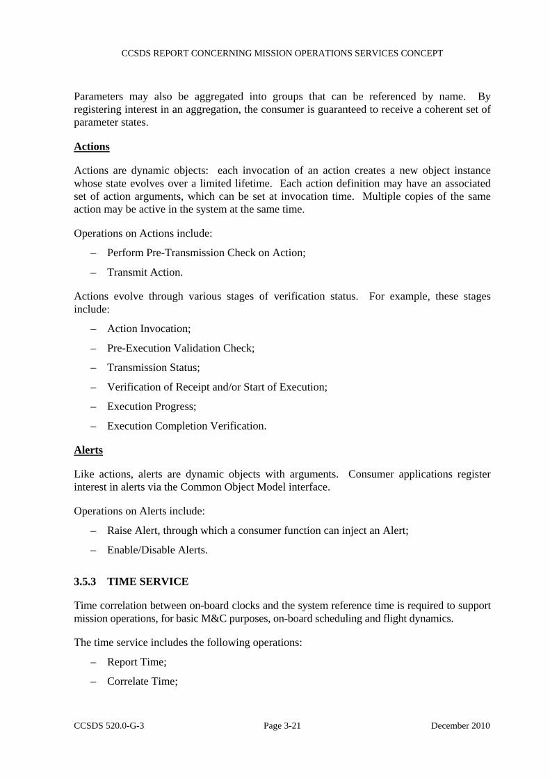
CCSDS REPORT CONCERNING MISSION OPERATIONS SERVICES CONCEPT
Parameters may also be aggregated into groups that can be referenced by name. By registering interest in an aggregation, the consumer is guaranteed to receive a coherent set of parameter states.
Actions
Actions are dynamic objects: each invocation of an action creates a new object instance whose state evolves over a limited lifetime. Each action definition may have an associated set of action arguments, which can be set at invocation time. Multiple copies of the same action may be active in the system at the same time.
Operations on Actions include:
– Perform Pre-Transmission Check on Action;
– Transmit Action.
Actions evolve through various stages of verification status. For example, these stages include:
– Action Invocation;
– Pre-Execution Validation Check;
– Transmission Status;
– Verification of Receipt and/or Start of Execution;
– Execution Progress;
– Execution Completion Verification.
Alerts
Like actions, alerts are dynamic objects with arguments. Consumer applications register interest in alerts via the Common Object Model interface.
Operations on Alerts include:
– Raise Alert, through which a consumer function can inject an Alert;
– Enable/Disable Alerts.
3.5.3 TIME SERVICE
Time correlation between on-board clocks and the system reference time is required to support mission operations, for basic M&C purposes, on-board scheduling and flight dynamics.
The time service includes the following operations:
– Report Time;
– Correlate Time;
CCSDS 520.0-G-3 Page 3-21 December 2010

CCSDS REPORT CONCERNING MISSION OPERATIONS SERVICES CONCEPT
– Set Time;
– Configure rate of Time Report generation.
3.5.4 SOFTWARE MANAGEMENT SERVICE
The Software Management service supports the management of software loaded into the remote system. At present, the service definition reflects the fact that most on-board software is managed in terms of binary images that are stored at known memory addresses. Future versions of the service may need to address on-board file-based systems. The operations supported include:
– Load Software Image;
– Dump Software Image;
– Check Software Image.
3.5.5 PLANNING REQUEST SERVICE
The Planning Request service allows a consumer application to raise a request (and responses) for an operational task or goal to be included in a plan. The service would be provided by a Mission Planning application; potential consumers include:
– Operations Team (via HCI);
– External Users (Principal Investigators, Mission Exploitation System, End Users);
– Flight Dynamics (manoeuvre requests);
– Software Management (software load requests).
The service definition does not prescribe the planning process or algorithms used by the Planning application. Nor does it address automation of the planning process, which can be achieved by the Planning application exposing the M&C service.
3.5.6 SCHEDULING SERVICE
The Scheduling service is one of two services that support automation of mission operations. Scheduling is concerned with the distribution, monitoring and control of scheduled timelines of mission operations intended for automated execution.
The service provider is an application capable of executing the schedule, whether ground-based or on-board the spacecraft. Consumer functions include Planning applications that generate schedules and require feedback on their execution, and Manual Operations displays that allow interactive monitoring and control of schedule execution.
The essential service object is a schedule which is a container for individual items that appear on the schedule timeline, including:
CCSDS 520.0-G-3 Page 3-22 December 2010

CCSDS REPORT CONCERNING MISSION OPERATIONS SERVICES CONCEPT
– Predicted Events;
– Planned Contacts (periods of connectivity between space and ground);
– Scheduled Tasks, potentially containing multiple Activities.
Predicted Events correlate to those notified via Flight Dynamics services, Scheduled Tasks correlate to a source Planning Request, while Activities correlate to individual Procedures or Functions that can be initiated via the Automation service.
Events, Tasks and Activities are defined in the service configuration data.
A Planning application generates a schedule for delivery via the service to the Schedule Execution function; it can also receive schedule status in return. A Manual Operations client can control the execution of the schedule and observe its dynamically evolving execution status via the service. The service also supports insertion, deletion and modification of individual scheduled items.
3.5.7 AUTOMATION SERVICE
The Automation service is the second of the two services that support automation of mission operations. The service provider is an application capable of executing pre-defined Procedures (or autonomous Functions), whether ground-based or on-board the spacecraft. Consumer functions include Schedule Execution and Manual Operations displays.
The essential service object is a procedure (or function) which may act as a container for constituent elements, including:
– Threads of execution control within the procedure;
– Execution Steps;
– Executable Actions.
The constituent Procedure Threads and Step objects are dependent on the model of procedure execution employed in the procedure definition. Executable Actions correlate to M&C Service actions, or the control of any other Mission Operations Service.
Schedule Execution or Manual Operations may invoke and execute a new instance of a procedure via the service. Subsequent control over the procedure may be exercised to suspend, resume or stop its execution, and to perform manual control over its execution. The execution status of the procedure can also be observed either at the level of the procedure object itself, or potentially at a lower level of detail in terms of the procedure model.
CCSDS 520.0-G-3 Page 3-23 December 2010

CCSDS REPORT CONCERNING MISSION OPERATIONS SERVICES CONCEPT
3.5.8 DATA PRODUCT MANAGEMENT SERVICE
The Data Product Management service is concerned with the management and transfer of sizeable binary data products. These products are typically observation or payload data gathered on-board the spacecraft, but they could also be used to manage the output of analysis and reporting functions.
The principal service objects are Products (Files) and Folders (Directories).
The service supports operations to:
– obtain explorer-style directory tree listings of the content of the remote data product store;
– transfer products in both directions (a service consumer can both get products from and put products into the remote data product store);
– perform data product store management operations, such as delete, move, rename, etc.;
– provide information about changes to the on-board data product store, such as new product events, etc.
It is anticipated that this service would be a thin layer over CFDP or FTP.
3.5.9 NAVIGATION SERVICE
The Navigation Service supports the provision of spacecraft positioning information. This includes (but is not limited to):
– position reports (e.g., from on-board GPS);
– spacecraft ranging and range-rate measurements (e.g., from ground station ranging or laser ranging equipment);
– antenna tracking azimuth and elevation (e.g., from ground station in auto-track mode);
– orbit vectors;
– attitude vectors;
– trajectory requests;
– predicted orbital events (including ground station visibilities).
The provider is either the spacecraft, a flight dynamics application, or a ground station facility. In the latter case, there is overlap with already identified Space Link Extension services. Any service definition in this area will be fully coordinated.
The service also includes operations required to initiate or control the frequency of acquisition/delivery of positioning measurements.
CCSDS 520.0-G-3 Page 3-24 December 2010

CCSDS REPORT CONCERNING MISSION OPERATIONS SERVICES CONCEPT
CCSDS 520.0-G-3 Page 3-25 December 2010
It is noted that a Flight Dynamics application may use other Mission Operations services to support aspects of its function. For example:
– planned manoeuvres may be communicated to other applications via the Planning Request or Scheduling services;
– automation of Flight Dynamics tasks can be achieved by the application exposing the M&C or Schedule Execution services.
3.5.10 REMOTE BUFFER MANAGEMENT SERVICE
As the connection to the spacecraft may be intermittent, many missions implement intermediate buffering of data either on-board the spacecraft or within a ground station. Such remote buffers may contain messages relating to any or all of the services described above.
The purpose of the Remote Buffer Management Service is to provide a standardised approach to the operation of such buffers. Supported operations include:
– Obtain Catalogue of Buffered Data;
– Retrieve Data from Buffer;
– Delete Data from Buffer;
– Clear Buffer.

CCSDS REPORT CONCERNING MISSION OPERATIONS SERVICES CONCEPT
4 DOCUMENT ROADMAP
4.1 OVERVIEW
This section summarises the set of standards documentation proposed in support of the Mission Operations Services Concept.
The following diagram presents the proposed top-level documentation set:
Mission Operations Services
TechnologyMappings
SpecificationsMO
Concept
ReferenceModel Common
Object Model
ApplicationProfile
LanguageAPI
ServiceSpecifications
ServiceSpecifications
MALEncoding
Service SpecificEncoding(optional)
Green Book
Blue Book
Magenta Book
LanguageMappings
MessageAbstractionLayer (MAL)
Figure 4-1: Top Level Document Set
NOTE – The Mission Operations Services Concept (this document) is an Informational Report. It proposes the specification of standards corresponding to the framework layers and the associated technology mappings: Message Abstraction Layer, Common Object Model, Mission Operations Services, Language and Technology mappings.
In the following subsections each of the documents is explained.
CCSDS 520.0-G-3 Page 4-1 December 2010
CCSDS REPORT CONCERNING MISSION OPERATIONS SERVICES CONCEPT
4.2 MISSION OPERATIONS SERVICE CONCEPT
The Mission Operations Services Concept document (this document) provides a complete overview for the entire collection of functions and services that are to be defined. This includes ground services to support mission operations and the respective flight-side elements. It also provides an overview of the specific services and how they relate to the missions operations functions that will use them.
4.3 REFERENCE MODEL
The Reference Model provides a common basis for coordinating the development of CCSDS Recommended Standards for Mission Operations service specifications and serves as a reference to maintain the consistency of these Recommended Standards.
4.4 MESSAGE ABSTRACTION LAYER
The Message Abstraction Layer (MAL) provides the basic toolkit of operations and messages that all services use to build their service specifications. It provides a standard abstract messaging service to the higher MO services so that they can concentrate on the service specifics and remain transport and encoding agnostic. The MAL formal specification defines the specific services required of the underlying message transfer service in terms of abstract service interfaces with requests, indications, and responses.
4.5 COMMON OBJECT MODEL
While the MAL provides the basic toolkit of operations and messages that all MO Services use to build their service specifications, the Common Object Model provides a standard service template, defined in terms of the MAL, that MO Service specifications extend.
4.6 SERVICE SPECIFICATIONS
The following diagram presents the document roadmap for the MO specifications that have been identified so far. These are the formalized, implementable specifications for each of the services that are defined to use the underlying MAL data types, message types, interaction patterns and the COM. While the MAL defines the baseline set of data types, message structures and set of possible interaction patterns, these Services specify the content and meaning of the messages they use to communicate their requests and responses, and the specific set of interaction patterns used to provide each service.
CCSDS 520.0-G-3 Page 4-2 December 2010

CCSDS REPORT CONCERNING MISSION OPERATIONS SERVICES CONCEPT
The document set contains the following set of formal, interoperable, specifications:
Common Services: Blue Book
Time Service: Blue Book
Software Management Service: Blue Book
Automation Service: Blue Book
Scheduling Service: Blue Book
Planning Request Service: Blue Book
Data Product Management Service: Blue Book
Navigation Service: Blue Book
Remote Buffer Management Service: Blue Book
MO Service Specifications
M&C Service: Blue Book
Future Service Specifications: Blue Book
Figure 4-2: Service Specification Document Roadmap
Each of these service specifications is defined in a complete, formal, unambiguous fashion, such that they can be directly implemented and tested. These are all defined using the services, protocols, messages, data types, and interaction patterns defined in the formal MAL document.
In addition to referencing the baseline MAL Blue Book, each Service formal specification will define the service offered and its behaviour in terms of requests, indications, and responses at this abstract interface. Each service will also define the formal message contents and meanings, using the relevant MAL Blue Book message structure and data type specifications, and each service will define its own behaviour in terms of internal operations and in terms of the set of interactions and message patterns that it exchanges with its peer service entity. These will all be defined in reference to the MAL Blue Book.
CCSDS 520.0-G-3 Page 4-3 December 2010
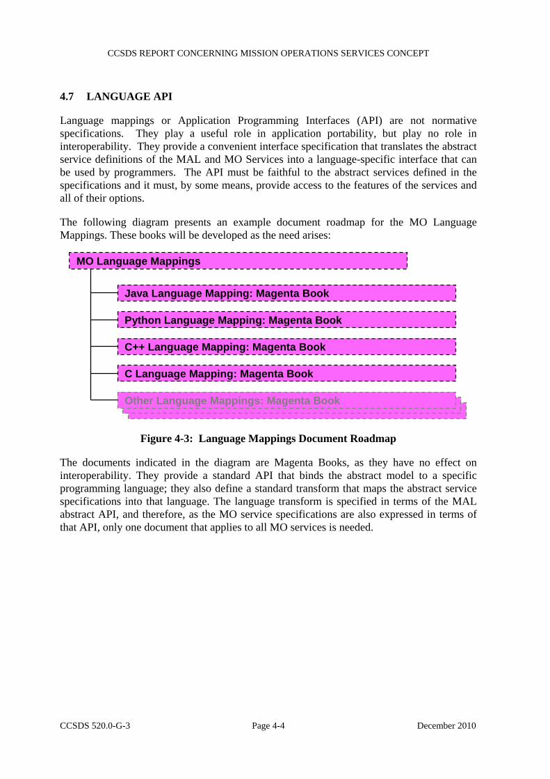
CCSDS REPORT CONCERNING MISSION OPERATIONS SERVICES CONCEPT
4.7 LANGUAGE API
Language mappings or Application Programming Interfaces (API) are not normative specifications. They play a useful role in application portability, but play no role in interoperability. They provide a convenient interface specification that translates the abstract service definitions of the MAL and MO Services into a language-specific interface that can be used by programmers. The API must be faithful to the abstract services defined in the specifications and it must, by some means, provide access to the features of the services and all of their options.
The following diagram presents an example document roadmap for the MO Language Mappings. These books will be developed as the need arises:
Java Language Mapping: Magenta Book
Python Language Mapping: Magenta Book
C++ Language Mapping: Magenta Book
C Language Mapping: Magenta Book
Other Language Mappings: Magenta Book
MO Language Mappings
Figure 4-3: Language Mappings Document Roadmap
The documents indicated in the diagram are Magenta Books, as they have no effect on interoperability. They provide a standard API that binds the abstract model to a specific programming language; they also define a standard transform that maps the abstract service specifications into that language. The language transform is specified in terms of the MAL abstract API, and therefore, as the MO service specifications are also expressed in terms of that API, only one document that applies to all MO services is needed.
CCSDS 520.0-G-3 Page 4-4 December 2010

CCSDS REPORT CONCERNING MISSION OPERATIONS SERVICES CONCEPT
4.8 TECHNOLOGY MAPPINGS
4.8.1 GENERAL
The lowest layer in the stack is the one that provides the actual message transfer and encoding service for the MAL.
The MAL formal specification defines the specific services required of the underlying message transfer service in terms of abstract service interfaces with requests, indications, and responses. A technology mapping translates these abstract required services into the capabilities provided in its concrete message transfer service.
The following diagram presents the document roadmap for the MO Technology Mappings:
Java JMS Encoding: Magenta Book
CCSDS Space Packet Encoding: Blue Books
CCSDS AMS Encoding: Blue Book
XML Encoding: Blue Book
Other Technology Mappings: Magenta/Blue Book
MO Technology Mappings
Figure 4-4: Technology Mappings Document Roadmap
The technology mappings must translate the MAL service and message model into a specific protocol tied to specific Protocol Data Units (PDUs). Each Technology Mapping Recommendation casts the MAL formal data types and messages into specific bit representations appropriate to that protocol.
It should be noted that mappings to transports that do not provide an interoperable protocol (such as Java JMS) cannot be considered as Blue Book, as they only define a mapping to an API and do not provide entity-to-entity interoperability. These will, however, be supported via the Magenta book standards path.
There are three types of encoding proposed, the primary one is a mapping from the abstract formal MAL notation to the specific technology, basically a mapping at the MAL level. There is one Blue Book per encoding that applies to all defined services.
The secondary case, the exception case, is where for optimisation reasons the data structures at the service level are mapped directly to the encoding. The rule here however is that the existing relevant MAL encoding is also used so that the layering is not violated.
CCSDS 520.0-G-3 Page 4-5 December 2010

CCSDS REPORT CONCERNING MISSION OPERATIONS SERVICES CONCEPT
CCSDS 520.0-G-3 Page 4-6 December 2010
The final case is for Best Practice purposes and provides an Application Profile of existing standards that should be used to achieve a specific goal.
4.8.2 MAL ENCODINGS
A MAL encoding-technology mapping defines a standard transform from the data types, message structure combination rules, and interaction patterns of the MAL into the relevant wire-level protocol and PDUs of that technology.
Because all service specifications are defined in terms of the MAL using a formal notation, the MAL mapping can be used, without modification, to transform the abstract notation of the service specifications into the relevant wire-level messages.
4.8.3 SERVICE SPECIFIC ENCODING
For cases where a service should be explicitly mapped into a technology for efficiency reasons then it is supported on the MO concept for that to be defined in a service specific encoding technology mapping Blue Book. A service specific encoding defines the exact representation for each service PDU in that technology rather than using the standard transform defined in the relevant MAL encoding; this allows optimisations to be made based on context specific knowledge.
It should be noted that a service-specific encoding does not break the layering concept as the service-specific encoding must still use the existing relevant MAL encoding. However, it may be the case that use of just the standalone MAL technology mapping is also possible, in which case it must be clear which is being used for a specific deployment either via agreement or through some aspect (header field for example) of that mapping.
4.8.4 APPLICATION PROFILE TECHNOLOGY MAPPING
An Application Profile provides a Recommended Practice of how to use a complete stack of protocols for a specific purpose, i.e., one or more Services, running over the MAL, mapped onto some specific underlying technology. It can also define how to bridge across two different technology mappings.

CCSDS REPORT CONCERNING MISSION OPERATIONS SERVICES CONCEPT
ANNEX A
DEFINITION OF TERMS Term Definition
action An atomic (non-interruptible) control directive of mission operations (equivalent to a telecommand or ground-segment directive) that can be initiated by manual or automatic control sources, via the M&C service. An action may have arguments and its evolving status can be observed. An action can typically apply pre- and post-execution checks.
activity An automated mission operations function; typically an operations procedure, batch task or other software process. An activity can be individually scheduled or initiated. In principle, an activity is non-atomic, has duration, and can be controlled once initiated. An activity may have arguments and its evolving status can be observed. An activity may generate multiple actions, and its behaviour can be dependent on status observed at run-time.
adapter In an SOA context, a software component that implements a higher-level service in terms of a lower-level service or specific technology. In this way different adapters can map a high-level service onto different underlying technologies, transparently to all higher layers including the application. Adapters can also wrap non–service-oriented applications so that they can be used as Service Providers in Service Oriented Architecture.
alert An asynchronous notification, such as a non-nominal event, of significance to mission operations. Alerts may be used to notify such events to operators, initiate an automatic response, or synchronise asynchronous functions. Alerts may have arguments.
application programmers’ interface
The definition of the exposed or ‘public’ interface to a software component that can be used by another software component. In an SOA context, an API corresponds to a language- or technology-specific implementation of an abstract service specification. This constitutes the code classes, types and functions utilised by a programmer when implementing the service provider and service consumer.
argument A run-time parameter provided to various control items on invocation, e.g., telecommand arguments. Arguments apply to actions, activities and alerts among other items.
CCSDS 520.0-G-3 Page A-1 December 2010

CCSDS REPORT CONCERNING MISSION OPERATIONS SERVICES CONCEPT
Term Definition
capability set A grouping of functions, offered by a service, that are logically related. Capability sets are used to decompose a service into smaller functional areas.
Common Object Model The generic service template that Mission Operations Services are defined in terms of.
consumer, service consumer
A software application that uses a service being supplied by a service provider. An individual software application can act as the consumer of multiple services.
domain A namespace that partitions separately addressable entities (e.g., actions, parameters, alerts) in the space system. The space system is decomposed into a hierarchy of domains within which entity identifiers are unique.
dynamic object dynamically instantiated object
An entity that is instantiated, invoked or created at run-time based on a static definition. Examples include actions, alerts and activities. Multiple copies (instances) of such objects may exist concurrently, but all share a single definition.
encapsulation A software design approach that provides code users with a well-defined interface to a set of functions in a way which hides their internal workings or means of implementation. In object-oriented programming, the technique of keeping together both data structures and the methods (procedures) which act on them.
event A time-stamped message, containing (changes in) information about information objects associated with a service, that is exchanged across service interfaces and potentially stored in service history.
exposed interface A published (or ‘public’) interface, provided by a software component, that is available for use by other software components.
Mission Operations Services
A suite of end-to-end application-level services that constitute a Service Oriented Architecture for space mission operations.
object/ information object/ service object
Information objects are passed across a service interface. These are defined in the information model of the service.
object instance Alternative term for object that distinguishes between the multiple run-time invocations of an object and their associated static definition (see statically and dynamically instantiated objects).
CCSDS 520.0-G-3 Page A-2 December 2010

CCSDS REPORT CONCERNING MISSION OPERATIONS SERVICES CONCEPT
Term Definition
operations In object-oriented programming, the methods / functions / messages defined for a Class of Objects. Specifically in the mission operations services context, the control primitives that can be performed across the service interfaces.
parameter An item of mission operations status information that can be individually subscribed to by a service consumer, via the M&C service. A parameter has multiple attributes, including: raw value, engineering value, validity, check status and (optionally) statistics.
plug-in A software component that can be integrated with other components conforming to the same Service Oriented Architecture, without the need to modify the implementation of other components. In the MO context, this could apply to both service consumer/provider applications and infrastructure components that implement lower levels (protocol layers) of the service interface.
protocol data unit Elemental data message for exchange between peer service layers of two applications using a particular implementation protocol.
provider, service provider
An application that publishes a service, exposing the service interface, while hiding details of its implementation.
proxy In the context of MO, a proxy function or component is one that acts locally in the place of a remote service provider, such as a spacecraft. There is a proxy function for each service. It provides a dual role. Firstly it provides a permanent point of contact for service consumers where the link to the remote service provider is intermittent, maintaining an image of current status, buffering operations and managing the service history. Secondly it can act as an isolation layer and adapter to actual protocols employed on the space-ground interface.
replay The act or interface associated with viewing data from a service history in the same manner as live operation. Service events are dynamically replayed over an evolving time period.
retrieval The act or interface associated with of withdrawing a data set by a time range from a service history. Retrieval is mainly intended for fast access to a block of service history for display of data trends or logs over a period of time, or to be used in analytical tasks.
CCSDS 520.0-G-3 Page A-3 December 2010

CCSDS REPORT CONCERNING MISSION OPERATIONS SERVICES CONCEPT
Term Definition
service, service interface
An abstraction of a function within a Service Oriented Architecture, as an exposed public interface, which allows independently developed applications to interact in a standard manner. Services should encapsulate concisely, representing only those information objects and operations needed at the abstract service interface. They should be platform and implementation independent.
service configuration data Configuration data (in the form of a database or other file) that defines the characteristics of a specific instance of a service. Typically this identifies the information objects that exist in the context of a particular service, for a particular domain, e.g., the specific actions, parameters and alerts applicable to a given spacecraft would be defined in the M&C service configuration data for that spacecraft. Access to the service configuration data is required by both service consumer and service provider (or its proxy).
service directory A service directory is an entity that provides publish and lookup facilities to service providers and consumers.
service history The operational data archive for a service. This is the data required to reconstitute a historical view of information at the service interface, either using replay or retrieval access methods. It corresponds to the persistent sequence of all service events over a period of time, to which a service consumer could have subscribed. Examples of service histories include parameter history, action history and alert history. Alternative implementations are possible, based on archiving of protocol messages (e.g., packets) and re-processing.
service instance A deployment copy of a service, typically for a specific domain. A service provider constructs and publishes a service instance. Service consumers may then subscribe to that service instance.
session A session defines the time-frame for a service. A session may be live or historical, real or simulated. A service consumer may join any existing session by subscribing to a service for that session. Within a given system there may be multiple concurrent sessions, to support simulated and/or historical replay sessions in parallel with live operations. Within service history there may be multiple session histories, corresponding to live operations and simulated sessions.
CCSDS 520.0-G-3 Page A-4 December 2010

CCSDS REPORT CONCERNING MISSION OPERATIONS SERVICES CONCEPT
CCSDS 520.0-G-3 Page A-5 December 2010
Term Definition
static object statically instantiated object
An entity that is effectively instantiated at operations preparation time, e.g., a parameter. It has a static portion (the definition) and a dynamic portion (its current status). See also dynamically instantiated object.


![AUTHORITY Completed... · CCSDS RECOMMENDATION FOR CCSDS [number] Page ii [May 2004] STATEMENT OF INTENT The Consultative Committee for Space Data Systems (CCSDS) is an organization](https://img.pdfslide.us/doc/110x75/60e73994dfac3b2061727d2d/authority-completed-ccsds-recommendation-for-ccsds-number-page-ii-may-2004.jpg)


![S2319HS Swivel 45.00 5.4 [0.21] co co Outline 520.0 [20.47 ... · S2319HS Swivel 45.00 5.4 [0.21] co co Outline 520.0 [20.47] 509.2 [20.05] dimension co co Unit Dimension Drawing](https://img.pdfslide.us/doc/110x75/5f2c0b79aedb327ea26f7d13/s2319hs-swivel-4500-54-021-co-co-outline-5200-2047-s2319hs-swivel-4500.jpg)


![CCSDS Historical Document › Pubs › 100x0g1s.pdf · CCSDS Historical Document ... [3]. Questions relative to the contents or status of this report should be addressed to the CCSDS](https://img.pdfslide.us/doc/110x75/5f0e30a57e708231d43e0a93/ccsds-historical-document-a-pubs-a-100x0g1spdf-ccsds-historical-document.jpg)