Embed Size (px)
Citation preview
Kremer 85
CCNS and AEROcontrol: Products for Efficient Photogrammetric Data Collection
JENS KREMER, Kreuztal
ABSTRACT
For the efficient airborne collection of photogrammetric data, the knowledge of the sensor’s position plays a crucial role in two different ways. On the one hand the precise measurement of the position and attitude of the sensor at a given instant is an important information for the geometric evaluation of the data. On the other hand the best knowledge of the position is worthless, if the used sensor was not taking data at the right position. To fulfill these two tasks of sensor positioning, the precise positioning and the guidance and sensor-management, the CCNS4 (Computer Controlled Navigation System) with the AEROcontrol option was developed by IGI. The CCNS4 together with the WinMP mission planning and documentation software is a GPS based guidance, positioning and management system for aerial survey flight missions. For the direct measurement of the exterior orientation elements of a sensor, the CCNS4 can be used with the AEROcontrol option. AEROcontrol is an integrated GPS/IMU system. This paper describes the system components, shows their function in a pratical survey flight mission and gives an example for the costs and possible savings of a project flown with or without the system.
1. INTRODUCTION
Since 1982 IGI is specialized in the development of guidance and management systems for aerial survey flight missions. The first systems were based on portable Precision-DMEs, Loran-C and DME-Tacan networks, since 1990 GPS is used. In 1996 IGI introduced the GPS/INS system AEROcontrol as an option for the CCNS4 to directly compute the position of a sensor at the instant of exposure. This system was based on an IMU with dry-tuned gyros and a 12-channel L1/L2 GPS receiver. Since 2000 the AEROcontrol-IId with a fiber-optic gyro based IMU is available for the precise measurement of the position and attitude of a sensor.
2. SYSTEM COMPONENTS
2.1. Mission Planning and Documentation: WinMP
WinMP is the latest software developed by IGI to plan and document aerial survey flight missions. WinMP runs under Windows 95/98/ME/NT/2000 on a standard office PC. The planning consists of waypoints, segments, flightlines, polygons, icons, text objects and digital maps. Digital raster or vector maps of many different formats like DXF, SHAPE, BMP, JPG, TIFF or GeoTIFF can be used as background maps for planning and mission documentation. The georeferencing of the maps can be calculated within the program. The missions can be planned and documented using a countries local Lat/Lon or X/Y coordinate system. IGI provides more than 70 Country Modules with hundreds of tested coordinate systems. The software automatically creates optimal flightline patterns for closed (i.e. blocks) and open polygons (for flying over power lines, rail tracks etc.). These proposed plannings can easily be modified by the user via a graphical interface. Customized reports of the mission planning and of the flown missions are created automatically. ASCII and DXF export is possible for all planning objects like waypoints and polygons.
'Photogrammetric Week 01' D. Fritsch & R. Spiller, Eds. Wichmann Verlag, Heidelberg 2001.

86 Kremer
Several databases are provided to store and manage data like:
• all information about flown missions (exposure positions, exposure times, film numbers…) • used background maps and their georeferencing parameters • different sensors • customized reports for different customers • index fields for planning overviews and photo indices for different purposes
WinMP provides interfaces to other flight management systems.
2.2. Guidance and Management System: CCNS4
The CCNS4 is a guidance, positioning and management system for aerial survey flight missions. The basic system consists of the Central Computer Unit (CCU) and the Command and Display Unit (CDU).
Figure 1: The CCNS4 CCU with 3” and 5” CDU
The system can be operated together with a large variety of different aerial cameras and other sensors (e.g. all Wild, Leica, Zeiss-Jena, Zeiss-Oberkochen aerial cameras, all current Z/I Imaging
and LH Systems camera systems and different laser scanners). The CCNS4 gets its positioning and velocity information from a GPS receiver, which is mounted inside the CCU, and optional heading information from the aircraft’s directional gyro. If the AEROcontrol option is operated, the directional information from the AEROcontrol IMU can be used. The GPS receivers are prepared for differential GPS operations according to RTCM-104 format. The directional information is used for a stable graphical display, allowing fast display reaction on aircraft maneuvers and for computing drift/grab
Figure 2: Guidance information on the display of a CCNS4 5” CDU during a photo flight (solid line → planned line;
dashed line → real track)

Kremer 87
for setting the camera mount. Corrections for local variations and aircraft’s deviations can be applied. To provide simple and error free operation by the pilot in the aircraft, the CDU is designed like an aircraft instrument. A computer keyboard is not necessary, all operations are controlled via two knobs and five buttons. The EFIS type display of the CDU is divided into a guidance and a system/sensor management part. To cover the planned flightlines, the pilot only has to align the needle that indicates the planned track and the line that indicates the correct real track (see figure 2). The screen can be zoomed to meet different requirements. Outputs with selectable sensitivity for aircraft instruments like Horizontal Situation Indicator (HSI) or Vertical/Crosstrack Deviation Indicator (VDI/CDI) instruments are provided. The CCNS4 is able to control two sensors at a time (e.g. a RC30 camera and a RMK-TOP camera). The actual flight data, including the aircraft position, are computed and can be provided for data annotation on film. Positions can be in WGS84 or a local coordinate system like UTM or Gauß Krüger. Waypoint data, flight information and GPS positions are stored on a PC-Card for mission documentation with WinMP.
2.3. GPS/INS System: AEROcontrol
Figure 3: AEROcontrol computer with Z-fly GPS receiver and IMU
Figure 4: Sensorblock of the IMU-IId with three accelerometers and three gyroscopes
To enable the CCNS4 to precisely measure the position and orientation of the airborne sensor, the AEROcontrol option was developed. AEROcontrol consists of three components:
• The Inertial Measurement Unit IMU-IId: The IMU includes three accelerometers, three fiber optic gyroscopes (500m fiber length) and signal pre-processing electronics. The six sensors are attached rigidly to an aluminum frame. Through wholes in the IMU housing, this sensor block is mounted directly to the used airborne sensor. The IMU-IId provides a high accuracy measurement of the angular rate and of the acceleration with an update rate of 64 Hz.
• The GPS antenna and receiver: The system can be operated with a number of different GPS receivers. The default configuration was the Z-fly (like in figure 3) and is now the Z-Xtreme receiver (Ashtech/Magellan, USA), both 12 channel dual frequency receivers.
88 Kremer
• The airborne computer unit: The airborne computer unit collects the raw data of the IMU and of the GPS receiver and stores them on a PC-Card for post-processing. It also provides the time synchronization between the GPS, the IMU and the used sensor. A real-time platform calculation allows to use the information as navigational input for the CCNS4. The system approximately records 12 MB of data per hour. For the example of a 192 MB PC-Card this results in a possible mission time of about 15 hours.
The system can read the attitude information of a stabilized camera mount (like Z/I Imaging’s T-AS or LH Systems’ PAV30) and store these values for a variable lever-arm correction in post-processing. If it is not possible to read the information from a used stabilized mount, an additional attitude sensor to monitor the mount angles is available from IGI. The AEROcontrol is controlled and operated via the CCNS4. With a new menu entry in the CCNS4, the recording of data can be switched on and off. On an additional info page the operator can monitor the data recording, supervise the GPS conditions and view the results of the real-time platform calculation. The CCNS4 computer unit and the AEROcontrol computer unit may be operated as separate devices or as one 19” rack solution. Mechanical adapters to mount the IMU-IId to metric aerial camera systems are provided by IGI.
2.4. Post-Processing and Data-Handling: AEROoffice
The AEROoffice software package is running under Windows 95/98/ME/NT/2000 on a standard office PC. It provides all functions necessary for the handling and evaluation of the collected GPS and IMU data, like:
• tools for handling the PC-Cards • differential GPS post-processing software • inertial navigation software • coordinate transformation to the local mapping system • attitude transformation to the local mapping system • misalignment transformation (boresight transformation) • lever-arm corrections for static and variable lever-arms • a graphical user interface
The processing time for the inertial navigation is less than thirty seconds per hour mission time on a 1GHz Pentium III with 128 MB RAM.
3. EXAMPLE OF A CCNS4/AEROcontrol PROJECT
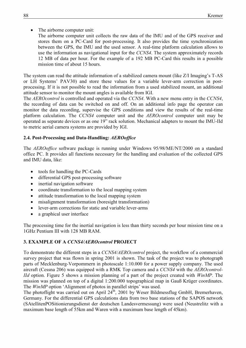
To demonstrate the different steps in a CCNS4/AEROcontrol project, the workflow of a commercial survey project that was flown in spring 2001 is shown. The task of the project was to photograph parts of Mecklenburg-Vorpommern in photoscale 1:10.000 for a power supply company. The used aircraft (Cessna 206) was equipped with a RMK Top camera and a CCNS4 with the AEROcontrol-IId option. Figure 5 shows a mission planning of a part of the project created with WinMP. The mission was planned on top of a digital 1:200.000 topographical map in Gauß Krüger coordinates. The WinMP option ‘Alignment of photos in parallel strips’ was used. The photoflight was carried out on April 24th, 2001 by Weser Bildmessflug GmbH, Bremerhaven, Germany. For the differential GPS calculations data from two base stations of the SAPOS network (SAtellitenPOSitionierungsdienst der deutschen Landesvermessung) were used (Neustrelitz with a maximum base length of 55km and Waren with a maximum base length of 45km).
Kremer 89
Figure 5: Flight planning on top of a digital map created with WinMP
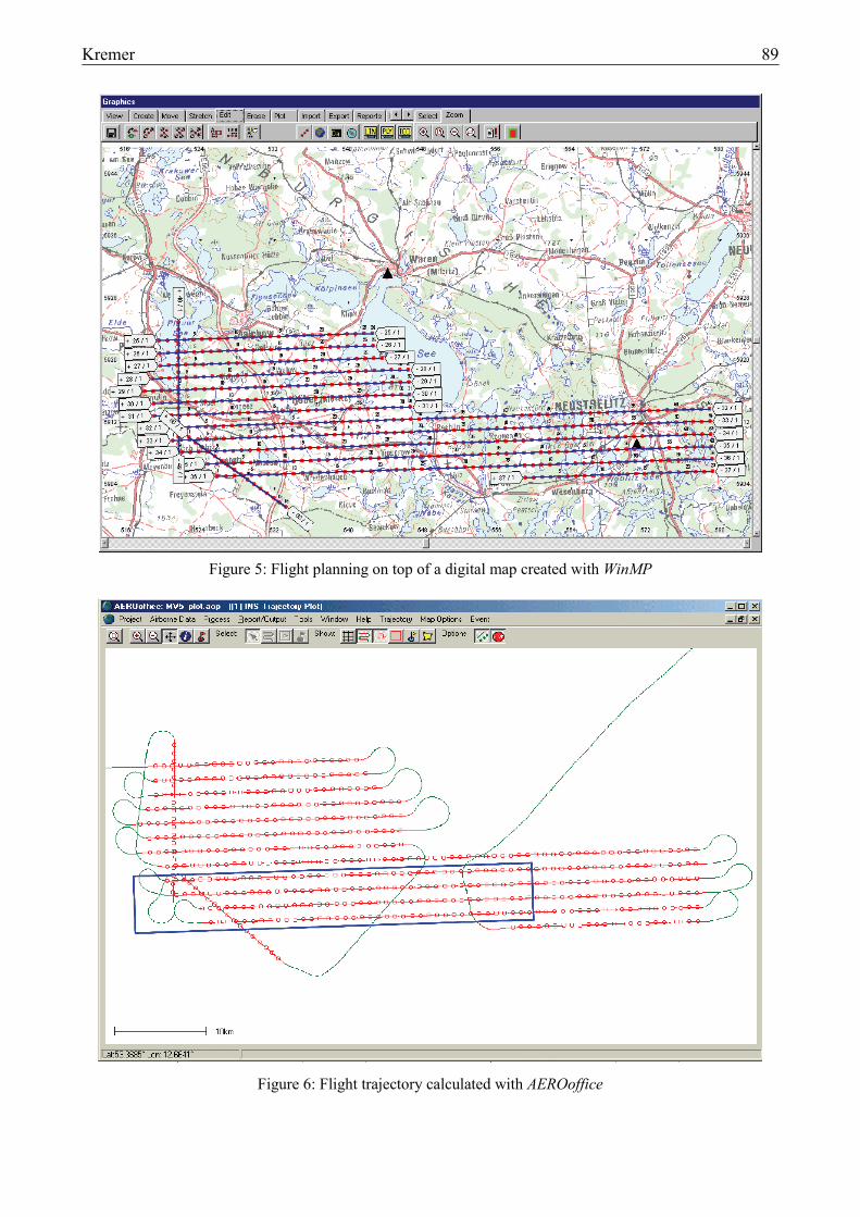
Figure 6: Flight trajectory calculated with AEROoffice
90 Kremer
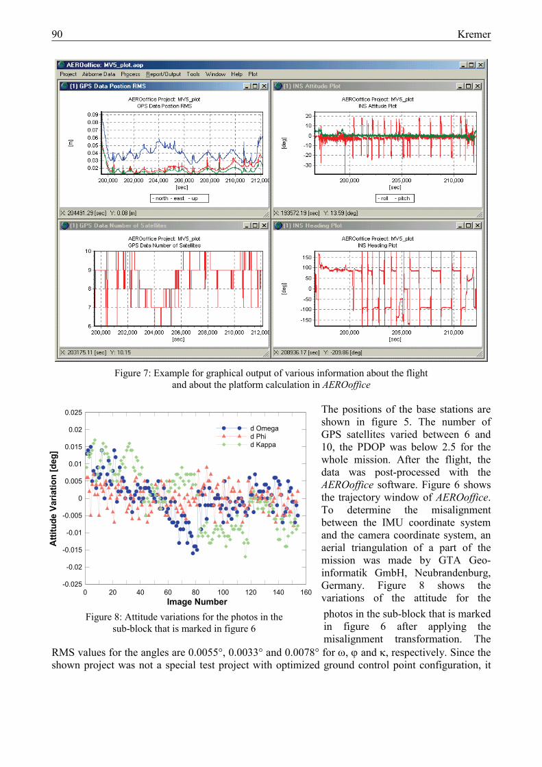
Figure 7: Example for graphical output of various information about the flight
and about the platform calculation in AEROoffice
The positions of the base stations are shown in figure 5. The number of GPS satellites varied between 6 and 10, the PDOP was below 2.5 for the whole mission. After the flight, the data was post-processed with the AEROoffice software. Figure 6 shows the trajectory window of AEROoffice. To determine the misalignment between the IMU coordinate system and the camera coordinate system, an aerial triangulation of a part of the mission was made by GTA Geo-informatik GmbH, Neubrandenburg, Germany. Figure 8 shows the variations of the attitude for the photos in the sub-block that is marked in figure 6 after applying the misalignment transformation. The
RMS values for the angles are 0.0055°, 0.0033° and 0.0078° for ω, ϕ and κ, respectively. Since the shown project was not a special test project with optimized ground control point configuration, it
Image Number
Attit
ude
Varia
tion
[deg
]
0 20 40 60 80 100 120 140 160-0.025
-0.02
-0.015
-0.01
-0.005
0
0.005
0.01
0.015
0.02
0.025
d Omegad Phid Kappa
Figure 8: Attitude variations for the photos in the sub-block that is marked in figure 6

Kremer 91
was not evaluated how strong these attitude variations were influenced by inaccuracies in the reference angles that were obtained from an AT.
4. COSTS AND POSSIBLE SAVINGS USING CCNS4/AEROcontrol
To show the possible economic benefits of the described system, the costs of a large survey project are compared in table 1. The supposed prices for hardware and labour are only estimations and should reflect the actual situation. For the estimation of the hardware costs it was assumed, that the hardware would be used for only one project per year. For the costs of the project without AEROcontrol, the costs for a guidance and sensor-management system (that are included in the costs for the AEROcontrol project) are not taken into account.
Workload GCP’s + ABGPS + AT AEROcontrol Project: Aerial photography for industrial use Photos: 15.000 Photo scale 1:10.000 30 blocks of aerial photography á 500 photos / block
Ground Control Points (GCP’s) and ABGPS 30 blocks á 10 GCP’s / block 300 GCP’s at 140 EUR / GCP
42.000 EUR
Aerial Photography 15.000 photos at 19 EUR / photo Cross strips (CS) for AT & ABGPS 2 CS / block 100 photos / block
285.000 EUR 285.000 EUR
30 blocks á 100 photos / block at 19 EUR / photo 57.000 EUR Aerial Triangulation (AT) 15,000 photos at 16 EUR / photo 240.000 EUR One Calibration Field for Boresighting 8 GCP’s / calibration field at 100 EUR / GCP 800 EUR 11 photos / calibrations at 19 EUR / photo for 30 calibrations (blocks) of aerial photography 6.270 EUR AT for 330 photos at 16 EUR / photo 5.280 EUR Boresighting / Calibration One calibration / block á 30 blocks 30 calibrations á 2 hours / calibration at 130 EUR 7.800 EUR DGPS Computation 30 missions (blocks) at 550 EUR / mission 16.500 EUR 16.500 EUR 15.000 photos at 1,30 EUR / photo 19.500 EUR 19.500 EUR AEROoffice Computation 30 missions (blocks) at 310 EUR / mission
9.300 EUR
15.000 photos at 0,60 EUR / photo 9.000 EUR CCNS & AEROcontrol instruments Amortization / year 40.000 EUR Interest / year 10.000 EUR Airborne L1/L2 Survey-GPS Receiver and Antenna
Amortization / year 4.500 EUR Interest / year 1.125 EUR Upgrades, Overhaul , Unforeseen 5.000 EUR 15.000 EUR
COSTS 670.625 EUR 424.450 EUR
SAVINGS 246.175 EUR
Table 1: Estimation of costs and possible savings for a large photo-project with and without AEROcontrol

92 Kremer
5. CONCLUSION
The CCNS4 has become a standard for guidance and management systems for aerial survey flight missions since many years. The new mission planning- and documentation software WinMP improves the efficiency of the data collection process by providing tools for the easy use of digital maps in many different formats, and, among other things, a number of databases to organize and document all information about past flight missions. With the AEROcontrol option for the CCNS4, a GPS/INS system was integrated into a guidance and management system. This system is currently used for airborne laser scanners, Synthetic Aperture Radar (SAR) and photogrammetry. The position accuracy of the AEROcontrol-IId depends on the GPS conditions. Experience shows that an absolute attitude accuracy of 0.005° for ω and ϕ, 0.01° for κ, and a position accuracy in the sub decimeter range are routinely achieved for reasonable GPS conditions (Heipke, 20011). In recent independent tests of the system it was shown, that under test conditions accuracies better than 0.003° for ω and ϕ, and better 0.006° for κ can be reached (Fritsch, 2000/Cramer, 2001). The use of the CCNS4 together with the AEROcontrol option provides the elements of the exterior orientation with a quality good enough for orthophoto production and for many photo-mapping applications. For other photo-mapping applications the AEROcontrol results are used as an additional input for a combined AT to reduce ground control, avoid cross strips, reduce computation time and support automated aerial triangulation (Sigle and Heuchel, 2001).
6. REFERENCES
Cramer, M. (2001): On the use of direct georeferencing in airborne photogrammetry. Proceedings of the 3rd. International Symposium on Mobile Mapping Technology, Cairo, Egypt.
Fritsch, D. (2000): Performance of the IGI AEROcontrol-IId GPS/Inertial System – Final Report, Available on request from IGI.
Heipke, C. (2001): The OEEPE Test on Integrated Sensor Orientation – Results from Phase 1. These Proceedings.
Sigle, M. and Heuchel, T. (2001): MATCH-AT: Recent Developments and Performance. These Proceedings.
1 The described test was performed with the predecessor of the AEROcontrol-IIb, a dry-tuned gyro based IMU with a lower accuracy.