Embed Size (px)
Citation preview

CCNPP 2/04 NRC EXAM DEVELOPMENT
Operations Training Unit
TO: FROM: SUBJ: DATE:
J. D’ Antonio, Chief Examiner, NRC Region 1 D. Lavato, Facility Representative 2/04 Initial License Operator Exam January 16,2004
I have encaed 19 JPMs, 2 (1 RO, 3 SRO) written examinations with associa.sd documentation, copies of required procedures for pedorming the JPMs and 4 scenarios with the required EOPdAOPs for the 2/04 Initial License Operator Examinations at Calvert Cliffs Nuclear Power Plant per NUREG 102 1 DraR Revision 9, ES 20 1 for your review. Copies of modified questions with their originals are also enclosed.
I have included Forms ES-301-3,4, 5 , 6 and ES-401-6 as required.
A copy of the audit exam which you requested is included. In accordance with Attachment 1 of ES 201, the enclosed materials “SHALL BE WITHHELD FROM PUBLIC DISCLOSURE UNTIL EXAMINATIONS ARE COMPLETE”.
If you need any additional information, please call me at (410) 495-4586 or Mike Wasem at (410) 495-3638.
Sincerely,
D. Lavato
cc: 2004 NRC exam file

3/04 NRc EXAM DEVELOPMENT Operations Training Unit
Two copies of each written exam are included. One copy is presented how the examinees will see it, including the handouts (references) they will be allowed to use. The other copy contains information that will help in your review process. This copy also contains the original question that was modified where applicable. I have included a marked-up question to explain the format of the information provided. I have also included marked up copies of the written outlines.

4) E f G tfi J
Given the following plant conditions:
-- Unit One has tripped due to a loss P-13000-1 -- 1 I 4KV bus is energized from 1A Diesel Generator --,' Pzr level is 100' and'slowly lowering -- RCS pressure is 1920 PSIA and slowly lowering
The RO reports that only 12 Charging Pump is running and Pressure and Inventory is Deing monitored for positive trends.
What alternate actions must the CRS direct or verify?
A. Verify SIAS actuation when RCS pressure reaches 1725 PSIA.
B. Manually start 1 I and 13 charging pumps to restore pressurizer level to greater
C. Isolate letdown, check that charging pumps automatically start to restore
than 1Ol"and locally reset 1 I pressurizer backup heater breaker.
pressurizer level and reset pressurizer proportional heaters by momentarily placing the handswitches to OFF.
D. Verify charging pumps start automatically to restore Pressurizer level to greater than I O I " , verify 12 and 14 pressurizer backup heaters start to restore RCS pressure.
A is incorrect, action should be taken so that SIAS does not actuate. B is correct, charging pumps must be manually started, and heaters must be reset, and they will not operate below 101" in the pressurizer. C is incorrect, letdown will automatically isolate, 11 and 13 charging pumps will not automatically start, and the proportional heaters will take a long time to restore RCS pressure. D is incorrect,l 1 and 13 charging pumps will not automatically start with the normal and alternate 4 KV bus feeder bkrs open and 12 and 14 heaters will not have power available. References: EOP basis docs. 41.5, 43.5

CCNPP 2/04 NRC EXAM DEVELOPMENT
Operations Training Unit
TO: FROM: Mike Wasem, exam author SUBJ: DATE: Feruary 11,2004
J. D’Antonio, Chief Examiner, NRC Region 1
2/04 Initial License Operator Exam
I have enclosed copies of the examination materials which include all the corrections and comments gathered during validation the week of February 2. Also, a proposed schedule and a copy of the security agreement with the most up to date signatures, as of today, are included.
In accordance with Attachment 1 of ES 201, the enclosed materials “ S U L BE WITHHELD FROM PUBLIC DISCLOSURE UNTIL EXAMINATIONS ARE COMPLETE”.
If you need any additional information, please call me at (410) 495-3638.
Sincerely,
Nb- Mike Wasem
cc: 2004 NRC exam file

Here is a quick summary of the changes from the originally submitted materials:
SRO Administrative Topics Outline-Changed A.2 descriptionof activity and WA
Control Roodn-Plant Systems Outlines---Changed S ystedJPM Title to reflect the change out of one in-plant JPM and the modification of one Control Room JPM
to better reflect intent of the JPM
SRO written: Incorporated comments on questions 1 , 2, 3,4, 6, 7, 9, 1 1 , 16, 19 and 21. Included Electrical System LCOs and basis to handout associated w/l5. Replaced questions 10 and 25.
RO written: Incorporated comments on questions 4, 12, 24 29, 32,42,45 and 73. Replaced questions 18, 50, 55 and 74.
Changes to the written exams resulted in changes to items 6 and 7 of the Written Examination Quality Checklist, Form ES-401-6 to: Bank Modified New 23/10 81 1 44/14
Memory CIA 34/11 41/14
Scenarios: Write ups of critical tasks. #l--correct load reduction target, referenced TS for PORV failure, Actions for possible 2 CPUs being failed and SRO referencing table for OTCC success. #Z-added referencing TS 3.6.6 for loss of CCW #3-reflect SGFP initial lineup change, addded details for expected actions shifting GS and SGFPs to Main Steam

CCNPP 3/04 NRC EXAM DEVELOPMENT
Operations Training Unit u
TO: FROM: D.F. Lavato, Facility Representative SUBJ: DATE: December 9,2003
J. D’ Antonio, Chief Examiner, NRC Region 1
3/04 Initial License Operator Exam Outlines
I have attached the required outlines for the March 2004 Initial License Operator Examinations at Calved Cliffs Nuclear Power Plant per NUREG 1021 Revision 9 ES 201.
Additional information is attached which includes the Random Selection method used for the Written exam development and a proposed exam week schedule.
In accordance with Attachment 1 ofES 201, the enclosed materials “SHALL BE WITHHELD FROM PUBLIC DISCLOSURE UNTIL EXAMINATIONS ARE COMPLETE”.
I have included form ES 201-2 with the test outlines. If you need any additional information, please call me at (410) 495-4586 or Mike Wasem at (410) 495-3638.
L .
Sincerely,
D.F. Lavato
cc: 2004 NRC exam file
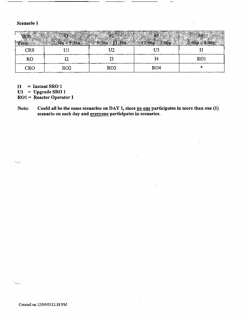
Scenario 1
CRS
RO CRO
u1 U2 u3 I1
I2 I3 I4 RO1 R03 R04 * R02
I1 = Instant SRO 1 U1 = Upgrade SRO 1 RO1= Reactor Operator 1
Note: Could all be the same scenarios on DAY 1, since no one participates in more than one (1) scenario on each day and everyone participates in scenarios.
Created on 12/09/03 12: 18 PM

Scenario 2
CRS
RO
CRO
I2 I3 I4
R02 R03 R04
RO1 I1 *
0 = Surrogate (can be same for both scenarios)
Created on 12/09/03 12: I8 PM

u 3 A1 .a U.b U.a A.1.b u.c I
I1
I2
I3
1.c A. 1 .b 1.a A.1.a 1.d
1.c A. 1 .b 1.d 1.a A. 1 .a
A.1.b 1.c A. 1 .a 1.d 1.a
I4
RO1
R02
U= upgrade
I= instant SRO
A=Admin -1 JPM
I
j R.d R..a R.h R.c A.1.b 1 I
1
1.a A.1.a 1.d 1.c A. 1 .b
-1 R.h R.d R.a A.1.b R.c
Created on 12/09/03 11:43 AM
R03
R04
R.c A.1.b R.a R.d R.h
A. 1 .b R.c R.h R.a R.d
NRC 1
NRC 2
u1 I1 I4 R03
U2 I2 RO1 R04

I €'V
P'V I €'V 1 zn I
h

In plant
R04
NOTE: The “Exit” will be as determined by the Lead Examiner.
Created on 12/09/0311:43 AM

E/APE #/Name/Safety Function I 4 1
- x
x
000007/E02 Reactor Trip - Recovery I1
000008 Pzr Vapor Space Accident 13
~~ ~ ~ ~
2.1.12 Ability to apply Technical Specifications for a system L C ~ S eb e/-./R sol 4.0 1
I / - e- - , A i 2.4.45 Ability to prioritize and interpret the s i g n i f i c f n $ % o t e o r & ad;? u” ’ 3.6 1
000009 Small Break LOCA 13
00001 1 Large Break LOCA 13
00001 5/17 RCP Malfunctions 14 I l l 000022 Loss of Rx Coolant Makeup 12
000025 Loss of RHR System 14
000026 Loss of Comp. Cooling Water I8
000027 Pzr Press. Ctrl. Sys. Malf. I3
000029 ATWS I1
000038 SG Tube Rupture13
000040CEO5 Steam Line Rupture 14
000054CE06 Loss of Feedwater 14
000055 Station Blackout 16 I l l 000056 /Loss of Off Site Power I6 I l l 000057 Loss of Vital AC Instrument Bus 16
000058 Loss of DC Power I6
000065 Loss of Instrument Air 18
CCNPP NRC License Examination March 2004 PWR Examination outline
Emergency and Abnormal Plant evolutions - 1 1 Tier Group (RO/SRO) Form ES-401-2
KIA Topics I Imp. I SRO#
I , , 1 , I 1
I x I I EA2.01 I Ability to determine or interpret reactor nuclear instrumentation as .mdeJt?a A W d I 4.7 I 1

E/APE #/Name/Safety Function K K K 1 2 3
oooOO1 Continuous Rod Withdrawal /I
oooO03 Dropped Control Rod / I
oooO05 InoperablelStuck Control Rod / I I I I oooO24 Emergency Boration /I
oooO28 /Pzr Level Malfunction I2 -
oooO32 Loss of Source Range NI ff I l l oooO33 Loss of Intermediate Range NI 17
oooO36 /Fuel Handling Accident /8 1
oooO37 SG Tube Leak /3 I l l oooO51 Loss of Condenser vacuum /4 I l l oooO59 Accidental Liquid RadWaste Rei. /9
oooO60 Accidental Gaseous Radwaste Re1.19 I oooO61 ARM System Alarms f f
oooO67 Plant Fire on Site /8
oooO68 Control Room Evac. /8 ~~
oooO69 Loss of CTMT Integrity /5 I l l oooO74 Inadequate Core Cooling 14
000076 Hiah Reactor Coolant Activity 19
CEIAI 1 RCS OvercoolinglPTS 14 I l l CE/A13 Natural Circulation /4
CE/A16 /Excessive RCS Leakage 12 ~ ~~~~~
CUE09 /Functional Recovery I l l KIA Category Totals
CCNPP NRC License Examination March 2004 PWR Es;lmination outline
Emergency and Abnorinal Plant evolutions -Tier 1 Group 2 (RO/SRo) Form ES-401-2
A A G Number KIA Topics Imp. SRO 1 2 #
I -T 1 I I -5. --.- -~ .
x 2.2.22 Kfmwledge of limiting yonditions for operations and safety limits u. -107- /--3-:-84.1 0 a?( 1
ations for system op
I
I I I
I Group Point Total

System #/Name l ~ l ~ l ~ l ~ l ~ l ~
003 Reactor Coolant Pump
004 Chemical and Volume Control
005 Residual Heat Removal
007 Pressurizer Relief/Quench Tank
008 Component Cooling Water I I I I I I 01 0 Pressurizer Pressure Control
01 2 Reactor Protection
01 3 ESFAS
022 Containment Cooling I I I I I I 039 Main and Reheat Steam
059 Main Feedwater
061 Auxiliary Feedwater I I I I I I
076 Service Water
078 Instrument Air
103 Containment
K/A Category Point totals
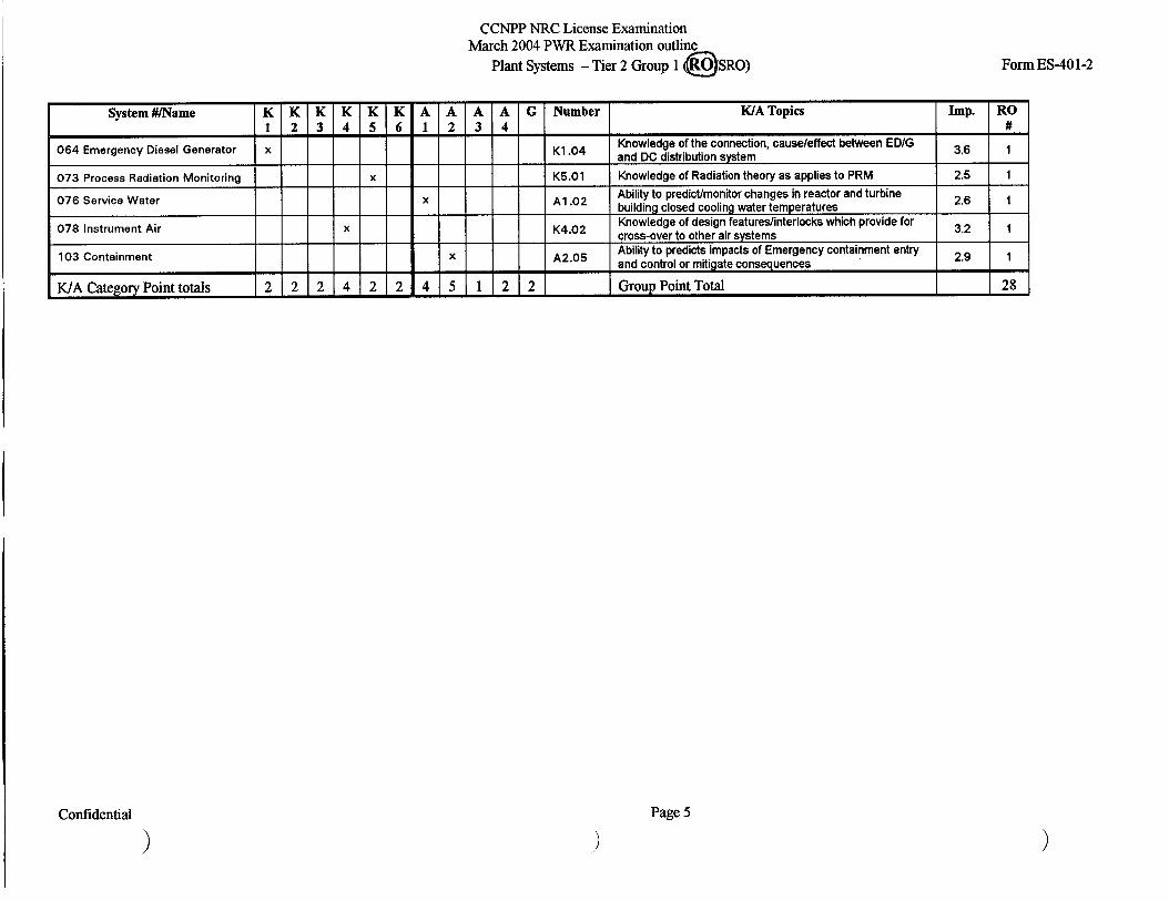
CCNPP NRC License Examination March 2004 PWR Examination outline
Plant Systems - Tier 2 Group 1 (RO/SRO) Form ES-401-2
W A Topics I Imp. I SRO
X Consequences of high or low flow rate and temperature: the 0 flow rate at which the CCW standby pump will start A2'07
h . 4 -----
. . I
X '2.04 3.2 I Ability to predict imp ts of and correct or control-Loss of service water c 0x4 \ v \ - ~ G JrzG fin\
T 1
1 2 1 I I 2 1 I Group Point Total

A A A A G Number KIA Topics Imp. 1 2 3 4
002 Reactor Coolant I I I I I I
SRO #
I I I I I I 01 1 Pressurizer Level Control
System #/Name
001 Control Rod Drive
01 4 Rod Position Indication
K K K K K E 1 2 3 4 5 6
1 1 1 1 1 1 X
01 5 Nuclear Instrumentation I I I I I I
A2.05 Ability to predict the impads of and correct or control-Loss of pressurizer 3.7 1 O E L heaters Ld Lfmr 5-Rx3
016 Non-Nuclear Instrumentation I I I I I I
027 Containment Iodine Removal
Control
029 Containment Purge
033 Spent Fuel Pool Cooling
034 Fuel Handling Equipment
035 Steam Generator I I I I I I 041 Steam DumplTurbine Bypass Control
~~~
068 Liquid Radwaste I I I I I I
072 Area Radiation Monitoring
079 Station Air ~
086 Fire Protection T I I I I I WA Category Point totals
CCNPP NRC License Examination March 2004 PWR E'uamination outline
Plant Systems - Tier 2 Group 2 (RO/SRO) Form ES-401-2
001 4.0 1 x 2.4.49 Ability to perform wlo reference to procedures actions that require
immediate operation w- I I 7- 6- c] -
1 1 Group Point Totat 2

1 Category WA #
2.1.2
2.1.15
Subtotal 2.2.22
Subtotal 2.3.3
2.3.7
Subtotal 2.4.4
2.4.18
Subtotal 1/ Tier 3 Point Total
CCNPP NRC License Examination March 2004 PWR Examination outline
Generic Knowledge and Abilities Outline (Tier 3)
Topic SRO-Only Imp. #
of plant 3.8 1
3.0 1 Ability to manage short-term information such as night and standing orders & rGkr$Nojd - 6 m SUI
Ability to recognize abnormal indications for system operating parameters which are entw level conditions for ememencv and I 4.3 1 1
> m ~ ES-401-3

CCNPP NRC License Examination ,L~uAI 2~0-4 PWR Esallhution O L ~ I ;d i t<
Emergency and Abnoriiial Plant evolutions - Tier 1 Group 1 (RO/SRO) Form ES-40 1-2
Number - K/A Topics Imp. RO #
I E/APE#/Name/SafetyFunction I 1
I EA1.06 4.4 I 1 I \ 000007lE02 Reactor Trip - Recovery 11 Verification that the control and safety rods are inefter the trip_ - 3 0 5 ~ .~
/
- r d( -c t3ol RCS pressure and temterature indicators and alarms ,,fdpofl Ability to operate and monitor the Containment Cooling System c Ki%wledge'of the InterTlations between Pumps and the Large Break LOCA %!- J,Q/- r-
3,dc
-,{, nkb- LcI' '* = f
Basic steady state thermodynamic unbdam&&SJ low
$1 I - 66 0
X I I AA2.01 000008 Pzr Vapor Space Accident 13
000003 Small Break LOCA 13
00001 1 Large Break LOCA 13
00001 511 7 RCP Malfunctions 14
EA1.07 + EK2.02
I AK1.04 x 2.4.21 Knowledge of parameters and logio used to assess the status of safey f ,\ 3.7 I
- . c cv
NOT SELECTED
AK3.02 -I- AK3.03 -1 3.6
Automatic actifis within the CCWS resulting from ESFAS a c t u a t i o w i ? ~, l 3 - C,T- & >
Actions oontainediin EOP for PZR PCS malfunction p Lx , '@e# "q flcf *
E A r u p t u r e d S I G T ~ -i;, G- I *;
Effects of feswater Introduction on dry S1Gj-f u+ - . MM line hdr($ 40 Restoration of power with one EDlG c j ~
OccurrenieTFa t k i n e trip LOSS fi 6 ~ , ~ ~ J ~ ~ ~
1 Effects of boron on reactivity, as it relates to an ATWW..>- I - 0 - 3 - 3-1 01 5-. , c -
j L &.,I 1 P l ~ ~ p rL ndl) - @, i 11, r)( & d!
I I
000027 Pzr Press. Ctrl. Sys. Malf. 13
-- _I-
-- --
000029 ATWS 11 I X EKI .03
$K3.01 AK1.07 F AKl.01
000038 SG Tube Rupture13 I ~~
000040CE05 Steam Line Rupture I4 I x
000054CE06 Loss of Feedwater 14 I x
I EA1.06 000055 Station Blackout I6
3.9 I I I I AA2.43 000056 /Loss of Off Site Power 16
000057 Loss of Vital AC Instrument Bus I6 f AA2.17 System and compone@atus, using local or remote controls . 3.1 I LiXs 66 v m i /SL 031
3.0 1
3.2 3.5
component status S isolation valves to
\LI 000058 Loss of DC Power 16 I I 000062 Loss of Nuclear Service Water 14
000065 Loss of Instrument Air 18
WA Category Totals 21 I I 1 1 8 1
Page 2

E/APE #/Name/Safety Function I K I K I K 000001 Continuous Rod Withdrawal 11
000003 DroDDed Control Rod 11 ~~
000005 InoperablelStuck Control Rod ITp- ~ I 1 I 000024 Emergency Boration 11
000028 1Pzr Level Malfunction /2
000032 Loss of Source Range NI i7
000033 Loss of Intermediate Range NI i7
000036 /Fuel Handling Accident I8
000037 SG Tube Leak /3
000051 Loss of Condenser vacuum 14
000059 Accidental Liquid RadWaste Rei. I9 000060 Accidental Gaseous Radwaste Re1.19
000061 ARM Svstem Alarms ff
000067 Plant Fire on Site 18
000068 Control Room Evac. 18
X
000069 Loss of CTMT Integrity 15
000074 lnadeauate Core Cooling 14
000076 High Reactor Coolant Activity 19 I I x I CE/AI I RCS OvercoolinglPTS 14
CE/AI 3 Natural Circulation 14
CVAI 6 /Excessive RCS Leakage I2
CE/EO9 /Functional Recovery
CCNPP NRC License Examination March 2004 PWR Examination outline
Emergency and Abnormal Plant evolutions - Tier 1 Group 2 (ROISRO) Form ES-40 1-2
A A G Number KIA Topics Imp. RO 1 2 #
6 lyl\
X M . 0 1 Ability to determine and interpret-Rod p o s M w k t u a l rod dosition 3.7 1
x 2.2.22 "Knowledge of limitivcondltlons for operation and safety limits kw ~p& 01 ; 3.4 1
L. I, -1 ,- . I
X M 2 . M Ability to determine and i " t e r ~ e t - u r r ~ ~ ~ ~ ~ i ~ ~ ~ ~ ' ~ I 3.4 1
x 2.1.1 Knowledge of condqbt of operations requhements flp& (28 I 3.7 1
~ ~ 3 . 0 4 & # & d e d in' EOP for plant fire on site . ~ L ) A . - 4q c ; q ~ 3.3 I '
X EA1.16
Aw.O1
''Abllityto operate and mmftor RCS incore thermocouple indicato~Q~-)/q- /-.el. &.$ (f&
J process radiation monitors 2.6 1 Knowledge of interrelations between the Hi h Reactor Coolant Activ3 and the 7 - lois I - ]-ry- o<q -
r - . I ,.".--
3.4 1
.3 EK3.4 ' KOowfedgafoFth~~~asbns'olRO'or SRO function within the control room team in such a way that procedures are adhered to and limlts are not violated l n [, - L?, , K..y - 159
I 2 1 2 2 Group Point Total 9
Codidential Page 3

CCNPP NRC License Examination Mdrch ~ W I J PLLREAAI~\I ILI~IW otriiil, .
Plant Systems - Tier 2 Group 1 (RO/SRO) Form ES-40 1-2
System #/Name K K K 1 2 3
53- ,“’” .*. * \ :. ’*’.- ‘“f,“
Q i +:(
3’
003 Reactor Coolant Pump
004 Chemical and Volume Control ?‘ 005 Residual Heat Removal : x
008 Component Cooling Water > ’~ 7 1, I 007 Pressurizer RelieflQuench 3 .’ Tank
~ 0 1 2 Reactor Protection
026 Containment Spray
:-.\ \ I - 1 I I 026 Containment Spray
(4 :) 7
$\ 1 039 Main and Reheat Steam ? 039 Main and Reheat Steam
* - - $ ’?
I 056 Condensate 1-1 I 059 Main Feedwater
059 Main Feedwater
061 Auxiliary Feedwater
061 Auxiliarv Feedwater
I 062 AC Electrical Distribution
063 DC Electrical Distribution 2 ‘ -
Confidential Page 4


System #&Name KIA Topics Imp.
001 Control Rod Drive
002 Reactor Coolant
01 1 Pressurizer Level Control
RO #
01 4 Rod Position Indication
Ability to manually operate the mode select for CRDS, operation of MG sets and control panel CR. o-. ( a&.)- oq Ability to predictlmonitor reactor power associated with RCS controls
01 5 Nuclear Instrumentation
3.7 1
- e
01 6 Non-Nuclear Instrumentation
01 7 In-Core Temperature Monitor
Knowledge of operational implications of differences betxeen RPlS
Ability to monitor recognition of audio output 5xpected for a given plant and step counter ('-bD ' &)- 4" 01-1 4
condition N I; IL xt m-mM9 (5 R >I
CCNPP NRC License Examination March 2004 PWR Examination outline
Plant Systems - Tier 2 Group 2 (ROISRO)
2.7 1
2.6
Form ES-401-2
Ability to manually operatelmonitor H2 sampling and analysis of cntmt atmosphere including alarms and indications f./.,., h/ I I \/It*-/ Knowledge of the design featurefinterlock providing auto isoiaion b4,j
A4.08
(3.1 1
rflQ$h.,&fY toAL<i& @I
K5.01
7
034 Fuel Handling Equipment
035 Steam Generator
041 Steam Dumpflurbine Bypass Control
3.0 Knowledge that t e effed of I of cooling has on spent fuel temperature [fi) __ -'L/-3-D!=. oZ3 /
WA Category Point totals 111 01 11 11 21 01 11 01 21 21 01
1
Confidential
Knowledge of operational implications of biolggical hazards of , radiation and resulting goal of ALARA ,!-I QL I f i &@a 1 e 00 1
Knowled e of connecfions and cause/effect betwezn ARM and Control Ffoom ventilation c . 0 /J 4 - 1 . 5 -9g qfy
3.2 1
3.3
Ability to manuall operatelmonitor starting echanisms of fire Pumps &&.G 5l/fir&Pl l.7 m7/ 2.9 1
Page 6

Category
Conduct of Operat iOl lS
Topic
Equipment 2. r \
3. 7s Control 3
control
4. Emergency Procedures
RO Imp. I #
WA #
Knowledge of shift turnover practices Sflr TU,@Q~'&. i',
Knowledge of conditions and limitations in the facility license
2.1.3 1 3 . a I 1 c &27~&#~1,]j 2.1.10
2.1.14
Subtotal 2.2.28
2.2.33 2.2.34
Subtotal 2.3.10
2.3.11
Subtotal 2.4.17
2.4.46
ICI 3PointTotaI Subtotal
Knowledge of system status criteria which require the notification of danimersonnel +i,<Thn <rfirJ< (L?tr/n I 2ii I I 1 I
process for determining the internal and 2.8 1 core reactivity Qkc L, f&Lj-lb$Ty dc/
I
FormES-401-3
Confidential Page 7

2/04 NRC Exam Outline Random Selection Method
Overview:
The Written Exam Outlines were developed per NUREG 1021 Draft Revision 9, ES-401 D. 1 and Attachment 1. Numbered tokens were used as described in the attachment 1 to develop both the RO and SRO Written Test Outlines.
Specific steps: The RO and SRO Written Exam outlines were made site-specific before any random selection was performed. For Tier 1 categories, the Westinghouse and B&W specific E/APEs were removed from the outlines. For Tier 2, Ice Condenser was removed from the outline.
For the SRO exam, only Categories A2, AA2, EA2 and G were maintained in the pool of available WA statements for selection in Tiers 1 and 2.
Rejected WA statements were replaced with randomly selected WA statements in the basic method specified in Attachment 1.
u

CCNPP NRC License Examination March 2004 PWR Written examination outline
Tier I Group I RO W A Category Points
I - I
2 I 18
1 2 2 2 4 2 2 4 5 1 2 2 28 2.
Plant Systems 2 1 0 1 1 2 0 1 0 2 2 0 10 Tier
Totals 3 2 3 5 4 2 5 5 3 4 2 38
3. Generic Knowledge and Abilities Categories
FormES-401-2
SRO-Only Points
Note: 1.
2.
3.
4. 5. 6. *
7.
8.
9.
Ensure that at least two topics from every WA category are sampled within each tier of the RO outline (i.e. the “Tier Totals” in each WA category shall not be less than two). Refer to Section D. 1.c for additional guidance regarding SRO sampling. The point total for each group and tier in the proposed outline must match that specified in the table. The final point total for each group and tier may deviate by f l from that specified in the table based on NRC revisions. The final RO exam must total 75 points and the SRO-only exam must total 25 points. Select topics from many systems and evolutions; avoid selecting more than two WA topics from a given system or evolution unless they are related to plant specific priorities. Systemdevolutions within each group are idenMied on the associated outline. The shaded areas are not applicable to the categoryltier. The generic (G) WAS in Tiers 1 and 2 shall be selected from Section 2 of the WA Catalog, but the topics must be relevant to the applicable evolution or system. The SRO UAs must also be linked to 10 CFR 55.43 or an SRO-level learning objective. On the following pages, enter the K/A numbers, a brief description of each topic, the topics’ importance ratings (R) for the applicable license level, and the point totals for each system and category. Enter the group and tier totals for each category in the table above; summarize all the SRO-only knowledge and non-A2 ability categories in the columns labeled “K” and “A”. Use duplicate pages for RO and SRO-only exams. For Tier 3, enter the WA numbers, descriptions, importance ratings, and point totals on Form ES-
Refer to ES-401, Attachment 2, for guidance regarding the elimination of inappropriate WA 401-3.
statements.
u
Confidential Page 1

E/APE #/Name/Safety Function
000007/E02 Reactor Trip - Recovery 11
000008 Pzr Vapor Space Accident 13 I I I 000009 Small Break LOCA /3 I l l 00001 1 Large Break LOCA 13
00001 5/17 RCP Malfunctions 14
X
X
000022 Loss of Rx Coolant Makeup /2
000025 Loss of RHR Svstem 14
000026 ~ o s s ofComp. Cooling Water 18 I I 1 x
000027 Pzr Press. Ctrl. Sys. Malf. I3 I I I x ~~
000029 ATWS I1 1 x 1 1 000038 SG Tube Rupture13 X
000040CE05 Steam Line Rupture 14 X
000054CE06 Loss of Feedwater 14 I x I I 000055 Station Blackout 16
000056 /Loss of Off Site Power 16
000057 Loss of Vital AC Instrument Bus /6
I l l 000058 Loss of DC Power 16
000062 Loss of Nuclear Service Water 14 I I I x
I l l 000065 Loss of Instrument Air 18 ~~~ ~
WA Category Totals
CCNPP NRC License Examination March 2004 PWR Examination outline
Emergency and Abnormal Plant evolutions - Tier 1 Group 1 e) Form ES-401-2
WA Topics I Imp. I RO 1 2 #
X EA1.06 Verification that the control and safety rods are in after the trip 4.4 I
x AA2.01 RCS pressure and temperature indicators and alarms 3.9 1
x I I 1 EA1.07 I Ability to operate and monitor the Containment Cooling Svstem I 3.7 I 1
EK2.02 Knowledge of the interrelations between Pumps and the Large Break LOCA 2.6 1
AK1.04 2.9 1
x 2.4.21 Knowledge of parameters and logic used to assess the status of safety functions 3.7 1
Basic steady state thermodynamic relationship between RCS loops and SlGs resulting from unbalanced RCS flow
I l l I NOT SELECTED I I AK3.02 Automatic actions within the CCWS resulting from ESFAS actuation 3.6 1
AK3.03 Actions contained in EOP for PZR PCS malfunction 3.7 I
I I I EK1.03 I Effects of boron on reactivity, as it relates to an ATWS I 3.6 I I
EK3.01 Equalizing pressure on primary and secondary sides of ruptured SIG 4.1 1
AK1.07 Effects of feedwater introduction on dry S/G 3.4 I
AK1.01 MFW line break depressurizes the SIG (similar to steam line break) 4.1 I
X EA1.06 Restoration of power with one ED/G 4.1 1
x AA2.43 Occurrence of a turbine trip 3.9 1
AA2.17 System and component status, using local or remote controls 3.1 I
3.0 I
3.2 1
X AA1.04 3.5 1
Ability to use plant computer to obtain and evaluate parametric information on System or component status The conditions that will initiate the automatic opening and closing of the SWS isolation valves to the nuclear service water coolers Ability to operate andlor monitor Emergency air compressors as applicable to loss of instrument
2.1
AK3'01
4 1 3 1 2 1 I I l8
Confidential
1 Page 2

D O 0 0 0 5 InoperabTelStuck Control Rod /l ~ I 1 000024 Emergency Boration ll I I WOO28 /Pzr Level Malfunction /2
000032 Loss of Source Range NI 17
000033 Loss of Intermediate Range NI /7 1 I 000036 /Fuel Handling Accident 18
000037 SG Tube Leak /3
000051 Loss of Condenser vacuum /4 I I 000059 Accidental Liquid RadWaste Rel. /9 I I 000060 Accidental G a s e o G d w a s t e Re1.19 I I 000061 ARM System Alarms /7
000067 Plant Fire on Site /8
000068 Control Room Evac. /8 I I 000069 Loss of CTMT Integrity 15
000074 Inadequate Core Cooling /4
I I x 000076 High Reactor Coolant Activity 19
CElA11 RCS OvercoolinglPTS /4
CElAl3 Natural Circulation /4 ~~
CE/AI 6 /Excessive RCS Leakage /2 I I CUE09 /Functional Recovery
CCNPP NRC License Examination March 2004 PWR Examination outline
Emergency and Abnormal Plant evolutions - Tier 1 Group 2@6$RO) Form ES-40 1-2 I
4 A G Number WA Topics Imp. RO 1 2 #
X AA2.01 Ability to determine and interpret-Rod position indication to actual rod position 3.7 1
x 2.2.22 Knowledge of limiting conditions for operation and safety limits 3.4 1
X AA2.02 Ability to determine and interpret-occurrence of a fuel handling incident 3.4 1
x 2.1.1 Knowledge of conduct of operations requirements 3.7 1
AK3.04 Actions contained in EOP for plant fire on site 3.3 1
X EA1 .16 Ability to operate and monitor RCS in-core thermocouple indicators 4.4 1
Knowledge of interrelations between the High Reactor Coolant Activity and the process radiation monitors 2.6 1 AK2.01
X AA1 .I 3.4 1 Ability to operatelmonitor components, functions of control and safety systems including instrumentation, signals, interlocks failure modes, autolman features Knowledge for the reasons of RO or SRO function within the control room team in such a way that procedures are adhered to and limits are not violated 3.3 EK3.4
2 1 2 1 2 1 I GrouD Point Total I 1 9
Confidential Page 3

CCNPP NRC License Examination March 2004 PWR Examination outlin
Plant Systems - Tier 2 Group 1 @SRQ Form ES-401-2
System #/Name K K K K K K 1 2 3 4 5 6
003 Reactor Coolant Pump
004 Chemical and Volume Control
005 Residual Heat Removal X
X
~ _ _
006 Emergency Core Cooling ~ I I x 1
I I I x I I I 008 Component Cooling Water System
007 Pressurizer RelieflQuench Tank
008 Component Cooling Water X
01 0 Pressurizer Pressure Control
01 2 Reactor Protection X
X
01 2 Reactor Protection
013 ESFAS
026 Containment Spray
039 Mainand Reheat Steam I I 1 I I I 039 Mainand Reheat Steam I I 1 1 I I
X Ability to predict the impacts of and correct, control or mitigate abnormal pressure in the PRT
The standby feature of the CCW pumps
A2'02
K4.09
K6.03 Knowledge of the effect of a loss or malfunction of PZR sprays and heaters will have on RCS PCS
K3.02 Knowledge that a loss or malfunction of the RPS will have on the TurbineIGenerator
x 2-4-47
Al
K1
K2.01
Abiliy to diagnose and recognize trends in an accurate and timely matter using reference material Ability to predcffmonitor changes in RCS pressure and temperature associated with operating ESFAS Knowledge of connections, cause effect relationship between CCS and SWS cooling system Knowledge of the bus Dower sumlies to CS PumDs
X
I I I I I - . . . . X Ability to predict impacts of and correct, loss of spray pump
suction when in recirc due to clogged screen, cavitation I A2.07
x I I I I I Al.09 I Ability to predicffmonitor changes in Main Steam line RMS
I I I x I I A4.01 I Ability to manually operatelmonitor MS supply valves
X A2.04
K4.08
Ability to predict impacts of loss of condensate pum ps...
FRV operation on basis of feedkteam flow mismatch
X A3.06 Abiliy to monitor MFW isolation I I I
Knowledge of the relationship between AFW flow and RCS I K5.01 I heattransfer
x I 1 I I I Al.03 I Ability to predicffmonitor interactions when units cross tied
X Ability to predict impacts, correct, de-energized loads that I A2'01 I degrade or hinder operation
I I I x I I A4.01 I Ability to operate or monitor breakers, fuses in the CR
+I 2.7
2.5
2.9
2.6
2.5
2.8
Confidential Page 4

CCNF'P NRC License Examination March 2004 PWR Examination outli
Plant Systems - Tier 2 Group 2 @SRO) Form ES-401-2
I System #/Name I KI a KI h 1 2 3 4
001 Control Rod Drive
I 002 Reactor Coolant I I I I 01 1 Pressurizer Level Control
01 4 Rod Position Indication
01 5 Nuclear Instrumentation
01 6 Non-Nuclear Instrumentation
0 1 7 In-Core Temperature Monitor
I 027 Containment Iodine Removal 1 I I I
041 Steam Dumpflurbine Bypass w Control
045 Main Turbine Generator
055 Condenser Air Removal
I 068 Liquid Radwaste I I I I 071 Waste Gas Disposal
072 Area Radiation Monitoring X
I I I I
075 Circulating Water
1 079 Station Air H I H I I 086 Fire Protection
WA Category Point totals 1 1 1 01 11 1
A A A A G Number KIA Topics Imp. RO 1 2 3 4 #
3.7 1 X A4.08 Ability to manually operate the mode select for CRDS, operation of MG sets and control panel
K A1 -06 Ability to predictlmonitor reactor power associated with RCS controls 4.0 1
2.7 1 K5.01 Knowledge of operational implications of differences between RPlS and step counter
A3'05 2.6 Ability to monitor recognition of audio output expected for a given plant condition
X
3.1 1 A4.03
K4.03 Knowledge of the design feature/interlock providina auto isolation 3.2 1
x Ability to manually operatelmonitor H2 sampling and analysis of cntmt atmosphere including alarms and indications
'3.03 3.0 1 Knowled e that the effect of loss of cooling has on spent fuel ternperatgure
3.2 1 K5.04 Knowledge of operational implications of biological hazards of radiation and resulting goal of ALARA
3.3 1 Kl.04 Knowledge of connections and causeleffect between ARM and Control Room ventilation
2.9 1 X A3.01 Ability to manually operatehonitor starting mechanisms of fire pumps
1 0 2 2 0 10
Confidential Page 6

Category
1. Conduct of Operations
2. Equipment Control
3. Radiation Control
4. Emergency Procedures I Plan
Tier 3 Point Total
KIA #
2.1.3
2.1.10
2.1.14
Subtotal 2.2.28
2.2.33 2.2.34
Subtotal 2.3.10
2.3.11
Subtotal 2.4.17
2.4.46
Subtotal
Confidential
CCNPP NRC License Examination March 2004 PWR Examination outline
Generic Knowledge and Abilities Outline (Tier 3) A0 1 Topic
Imp. # Knowledge of shift turnover practices 3.0 1
Knowledge of conditions and limitations in the facility license Knowledge of system status criteria which require the notification of plant personnel
2.7 1
2.5 1
Y&g&; 3 I 2.6 1 Knowledge of new and spent fuel movement procedures
Knowledge of control rod programming 2.5 1
Knowledge of the process for determining the internal and external effects on core reactivity
2.8 1
Ability to perform procedures to reduce excessive levels of
Ability to control radiation releases 2.7 1
2.9 1 radiation and guard against personnel exposure
I
Knowledge of EOP terms and definitions 1
3.5 1 Ability to verify that alarms are consistent with plant conditions
Page 7
Form ES-401-3 n
n

E / N E #/Name./Safety Function
000007/E02 Reactor Trip - Recovery 11
000008 Pzr Vapor Space Accident 13
000009 Small Break LOCA 13
00001 1 Large Break LOCA 13 I l l 00001 511 7 RCP Malfunctions 14
000022 Loss of Rx Coolant Makeup 12
000025 Loss of RHR System 14 H I 000026 Loss of Comp. Cooling Water 18 I I I
~~
000027 Pzr Press. Ctrl. Sys. Malf. 13 I 1 I 000029 A W S I1 I l l 000038 SG Tube Rupture13
000040CE05 Steam Line Rupture 14 ~~ ~ ~ ~~
000054CE06 Loss of Feedwater 14 I I I
000056 /Loss of Off Site Power 16
000058 Loss of DC Power 16
000062 Loss of Nuclear Service Water 14
000065 Loss of Instrument Air 18
K/A Category Totals
CCNPP NRC License Examination March 2004 PWR Examination outline
Emergency and Abnormal Plant evolutions - Tier 1 Group 1 ( R o e Form ES-401-2
G Number WA Topics Imp. SRO#
m . 1 0 When to secure RCPs on loss of cooling or seal injection 3.7 1
x 2.1.12 Ability to apply Technical Specifications for a system 4.0 1
x 2.4.45 Ability to prioritize and interpret the significance of each annunciator or alarm 3.6 1
EA2.01 Abilitv to determine or interwet reactor nuclear instrumentation as it amlies to a ATWS 4.7 1
AA2.08 Ability to determine and interpret Steam flow-feed trend recorder 3.3 1
x 2.1.20 Ability to execute procedure steps 4.2 I
I I 4.1 1 Ability to determine and interpret that a loss of dc power has occurred: verification that
substitute power power sources have come on line AA2.0’

E/APE MNamdSafets Function I K I K I K
000001 Continuous Rod Withdrawal 11
000003 Dropped Control Rod I1
000005 InoperablelStuck Control Rod 11 I I I 000024 Emergency Boration 11
000028 1Pzr Level Malfunction 12
000032 Loss of Source Range NI 17 I l l 000033 Loss of Intermediate Range NI /7
000036 /Fuel Handling Accident 18
I l l 000037 SG Tube Leak /3
000051 Loss of Condenser vacuum /4 I l l 000059 Accidental Liquid RadWaste Rel. /9 000060 Accidental Gaseous Radwaste Re1./9
000061 ARM System Alarms i7 I l l 000067 Plant Fire on Site 18 I l l
I l l 000068 Control Room Evac. 18
000069 Loss of CTMT Integrity 15 I l l 000074 Inadequate Core Cooling 14
000076 High Reactor Coolant Activity /9
CE1A1 1 RCS OvercoolinglPTS 14 I l l CE/AI 3 Natural Circulation /4
CE/A16 /Excessive RCS Leakage 12
CEIEO9 /Functional Recovery
CCNPP NRC License Examination March 2004 PWR Examination outline
Emergency and Abnormal Plant evolutions - Tier 1 Group 2 ( R O B Form ES-401-2
A I A I G I Number I KIA Topics I Imp. I SRO
x 2.2.22 Knowledge of limiting conditions for operations and safety limits 4.1 1
4.0 1 ' Abiliy to recognize indications for system operating parameters which are entry- level conditions for technical specifications 2'1 .33
3.7 1 x Knowledge of bases in technical specifications for limiting conditions and safety limits 2.2.25
X 3.5 , AA2.1
X EA2.1
Facility conditions and selection of appropriate procedures during abnormal and emergency conditions Facility conditions and selection of appropriate procedures during abnormal or emergency operations 4.4
2 3 5

CCNPP NRC License Examination March 2004 PWR Examination outline
Plant Systems - Tier 2 Group 1
A A 1 2
X
X
2
Form ES-401-2
1 006 Emergency Core Cooling I I I I I I 007 Pressurizer Relief/Quench
01 0 Pressurizer Pressure Control
I I I I I I I 022 Containment Cooling I I I I I I 026 Containment Spray
039 Main and Reheat Steam
056 Condensate
E n Feedwater I I I I I I I 061 Auxiliary Feedwater I I I I I I
076 Service Water
078 Instrument Air
103 Containment
I WA Category Point totals
W
A A G Number K/A Topics Imp. SRO 3 4 #
2.8 1 Consequences of high or low flow rate and temperature: the flow rate at which the CCW standby pump will start A2*07
3.2 1 Ability to predict impacts of and correct or control-Loss of service water
x 2.1.32 Ability to explain and apply all system limits and precautions 3.8 1
3.3 1
2 Grout, Point Total 4
Knowledge of system status criteria which require the notification of plant personnel 2.1

System m a m e IK
001 Control Rod Drive
002 Reactor Coolant I 0 1 1 Pressurizer Level Control
01 5 Nuclear Instrumentation I 01 6 Non-Nuclear Instrumentation I 01 7 In-Core Temperature Monitor I
028 H2 Recombiner and Purge Control
029 Containment Purge I
034 Fuel Handling Equipment
041 Steam Dumpflurbine Bypass Control
045 Main Turbine Generator
055 Condenser Air Removal
068 Liquid Radwaste
071 Waste Gas Disposal I 0 7 2 Area Radiation Monitoring I 075 Circulating Water
079 Station Air
086 Fire Protection
WA Categorv Point totals
CCNPP NRC License Examination March 2004 PWR Examination outline
Plant Systems - Tier 2 Group 2 ( R O a Form ES-401-2
WA ToDics
X A2.05 Ability to predict the impacts of and correct or control-Loss of pressurizer 3.7 1 heaters
4.0 1 x 2.4.49 Ability to perform wlo reference to procedures actions that require immediate operation
I l l I I l l I Grouo Point Total I 1 2

Category
1. Conduct of Operations
2. Equipment Control
3. Radiation Control
4. Emergency Procedures I Plan
Tier 3 Point Total
K/A #
2.1.2
2.1.15
Subtotal 2.2.22
Subtotal 2.3.3
2.3.7
Subtotal 2.4.4
2.4.18
Subtotal
CCNPP NRC License Examination March 2004 PWR Examination outline
Generic Knowledge and Abilities Outline (Tier 3) SRO 1 Topic I SRO-Only
I ImD. I #
Knowledge of operator responsibilities during all modes of plant 3.8 1
3.0 1
operation Ability to manage short-term information such as night and standing orders
Ability to recognize abnormal indications for system operating parameters which are entry level conditions for emergency and abnormal operating procedures
4.3 1
Knowledge of the specific bases for EOPs 3.6 1
~ r m ES-401-3 -,

Tier I Group
Randomly Reason for Rejection Selected WA
RO EXAM
111
111
1 I1
111
026AKl. None listed, selected 026AK3.01
056AK2.07
057AK1. None listed, selected 057AA2.17
065AA1.05
Low RO importance, selected 056AA2.43
RPS unaffected by loss of IA, selected 065AA1.04
111 027AK3.04 Routine Rx tri! gressure restor s at he am time or before level, I due ti hinh he t r capacity-seeected 02Qk3.83 111
211
211
21 1
211
211
WS valves to CCWS coolers receive no automatic signals, selected 8.02
026AK3.0 1
026K5.
039K2.
076K6
078K6
004K4.14
None > 2.5, selected 026A2.07
None > 2.5, selected 039A1.09
None > 2.5, selected 076A1.02
None > 2.5, selected 078K4.02
Over sampled K4, selected 004K6.04 211 Same WA e e d I st exam, mi i al uestions tg mgtch WA,
replaced [email protected]?to preservem nlmber distribution 007K3.01
212
212
212
212
111
1 I1
211
014A3. None listed, selected 014K5.01
027A2.01
029K6. None listed, selected 029K4.03
001A4.12
IRU high temps not addressed in procedures, spray retired in place, selected 002A1.06
Not applicable, no limit to prevent coil burnout, selected 001A4.08
SRO EXAM
055 2.1.6
026 2.1.12
059 2.1.14
Not applicable to SRO during SBO, selected 2.1 20
Over sampled CC system, selected APE 025
Over sampled Main Feed, selected 103 (Containment)

ES-301 Control Roodln-Plant Systems Outline Form ES-301-2
Facility: CCNPP Date of Examination: 03/01/2004 Exam Level (circle one):
Control Room Systems (8 for RO; 7 for SRO-I; z or 3 for SRO-U)
SRO(I) / SRO(U) Operating Test No.: Y
System/JPM Title
a. CVCSIShift Charging Pumps per OI-2A (Discharge relief lifts on started pump)
004A2.22 3.2/3.1
b. ECCSiTest LPSl check valves per STP-0-65-1 006A4.02 4.0/3.8
~
c. RHWlnitiate SDC (An RCS leak develops when suction MOVs are opened) 005A1.05 3.3/3.3
Emergency Diesel Generatorsnransfer 4 KV bus from an EDG d. to Offsite Power
064A4.06 3.9/3.9
e. Control Rod Drive System/Realign a CEA (CEA drops when moved) 003AA1.02 3.6/3.4
Verify the Containment Environment Safety Function f. 022A4.01,4.04 3.9/3.8 and 3.W3.2
g. Process RMS/Test Containment Atmosphere Rad. Mon. per STP-0-33- 1
073A4.03 3.V3.2
h. Secure a Circulating Water Pump per OI-14A 075A2.02 2.5/2.7
Type Code*
N S
Safety Function
2
3
4-primary

I. Align AFW pump speed/flow control to 1 (2)C43 068AA1.12 4.4/4.4
j. ESFAS/Re-energize ESFAS cabinet per 01-34
k. Liquid RadWasteIPerform flush of Rad. Monitor per OI-17C. (Discharge valve shuts during flush)
013K2.01 3.6/3.8
068A3.02 3.6/3.6
NUREG-1021, Draft Revision 9
D 4 secondary
D 2
N,R,A 9

ES-301 Control Room/ln-Plant Svstems Outline Form 13-301 -2
Facility: CCNPP Date of Examination: 03/01/2004 Exam Level (circle one): RO / SRO(I) / SRO(U) Operating Test No.:
Control Room Systems (8 for RO; 7 f o e z or 3 for SRO-U)
System/JPM Title
a. CVCS/Shift Charging Pumps per OI-2A (Discharge relief lifts on started pump)
004A2.22 3.2/3.1
b. ECCS/Test LPSl check valves per STP-0-65-1 006A4.02 4.0/3.8
c. RHWlnitiate SDC (An RCS leak develops when suction MOVs are opened) 005A1.05 3.3/3.3
Type Code*
N, A, s
d. Emergency Diesel Generatorsmransfer 4KV loads from an EDG to Offsite Power
064A4.06 3.913.9
e. Control Rod Drive System/Realign a CEA (CEA drops when moved) 003AA1.02 3.6/3.4
f. Verify the Containment Environment Safety Function 022A4.01.4.04 3.9/3.8 and 3.113.2
N, s g. Process RMS/Test Containment Atmosphere Rad. Mon. per
STP-0-33-1 073A4.03 3.1/3.2
h.
Safety Function
2
3
4-primary
6
7

D 1. Align AFW pump speed/flow control to 1 (2)C43
068AA1.12 4.4/4.4 D
4 secondary
2 j. ESFAS/Re-energize ESFAS cabinet per 01-34
013K2.01 3.6/3.8 NR,A
k. Liquid RadWaste/Perform flush of Rad. Monitor per 01-1 7C. (Discharge valve shuts during flush)
068A3.02 3.6/3.6
9

NUREG-1021, Draft Revision 9 ES-30 1 Control Roomlln-Plant Systems Outline Form ES-301-2
Type Code*
Facility: CCNPP Date of Examination: 03/01/2004 Exam Level (circle one): RO / SRO(I) / SRO(U) Operating Test No.:
Control Room Systems (8 for RO; 7 for SRO-I; 2 or 3 for
Safety Function SystemlJPM Title
1. Align AFW pump speed/flow control to 1 (2)C43 068AAl . I2 4.414.4
j. Liquid RadWaste/Perform flush of Rad. Monitor per OI-17C. (Discharge valve shuts during flush)
068A3.02 3.6/3.6
a. CVCS/Shift Charging Pumps per OI-2A (Discharge relief lifts on started pump)
004A2.22 3.2/3.1
b. Emergency Diesel Generatorsmransfer 4 W bus from an EDG to Offsite Power 064A4.06 3.9/3.9
C. RHRllnitiate SDC (An RCS leak develops when suction MOVs are opened) 005A1.05 3.3/3.3
D 4 secondary
N I RIA 9
d.
e.
f.
In-Plant Systems (3 for RO; 3 for SRO-I; 3 or 2 for
N,A,L,S 4-primary -7- 1
I >
RO-d

NUREG-1021, Draft Revision 9 ES-301 Administrative Topics Outline Form ES-301-1
Facility: CCNPP Date of Examination: 03/01/2004
1 Examination Level (circle one):@/ SRO Operating Test Number:
Administrative Topic (see Note)
A. 1 .a Conduct of Operations
A.1 .b Conduct of Operations
A. 2
Equipment Control
A. 3
Radiation Control
A.4
Emergency Plan
Describe activity to be performed
2.1.19 3.0 Ability to use plant computer to obtain and evaluate parametric information on plant system or component status
Enter feed flow correction factors into the plant computer per OI-50A, verifying NI calibration. 2.1.25 2.8 Ability to obtain and interpret station reference materials such as graphs, monographs, and tables which contain performance data
Verify shutdown margin in mode 3 with one stuck CEA 2.2.13 3.6 Knowledge of tagging and clearance procedures
Verify tagout boundaries per NO-1-112
2.4.43 2.8 Knowledge of emergency communications and techniques
Recall station personnel due to a hurricane warning per ERPIP 3.0 Att. 20, D.5.0
NOTE: All items (5 total) are required for SROs. RO applicants require only 4 items unless they are retaking only the administrative topics, when 5 are required.

NUREG-1021, Draft Revision 9 ES-30 1 Administrative Topics Outline Form ES-301-1
~~
Facility: CCNPP Date of Examination: 03/01/2004
Examination Level (circle one): RO /@Operating Test Number:
Ad mi n istrat ive Topic (see Note)
A.1 .a Conduct of Operations
A.l .b Conduct of Operations
A. 2
Equipment Control
A. 3
Radiation Control
A.4
Emergency Plan
Describe activity to be performed
A.l . I 240 Ability to apply technical specifications to a system
Review /Approve an IR for Operability determination
2.1.25 3.1 Ability to obtain and interpret station reference materials such as graphs, monographs, and tables which contain performance data
Verify an ECC 2.2.13 3.8 Knowledge of tagging and clearance procedures
Approve a clearance or restoration per NO-1-112
2.3.6 3.1 Knowledge of the requirements for reviewing and approving release permits
Review an RCWMT discharge permit
2.4.44 4.0 Knowledge of emergency plan protective action recommendations
Classify an EAL and provide protective action recommendations per the ERPIP
NOTE: All items (5 total) are required for SROs. RO applicants require only 4 items unless they are retaking only the administrative topics, when 5 are required.

Simulation Facility Calvert Cliffs ScenarioNo.: 1 Op Test No.: 1
Examiners: operators: SRO
To evaluate the applicant’s ability to conduct a unit power decrease and implement the ARUS, Oh, AOPs, as appropriate, for malfunctioning systems andor controls including failure of a VCT level Transmitter with an intermediate indication on suction switchover, erratic operation of a FW controller, and a dropped CEA. After the unit is stabilized, the System operator directs power be reduced 100 MWe in the next 10 minutes. Once power is stabilized, a high SGFP vibration alarm occurs followed shortly thereafter by a SGFP trip. After it is determined the SGFP cannot be reset, the unit is tripped and EOP-0 entered. The feed system pernubation causes a feed rupture. A blockage in the AFW suction line prevents AFW flow from being established requiring EOP-3 be implemented. The crew will attempt to restore feed and then initiate OTCC. Upon initiation of OTCC, one PORV will not open.
Dbjectives:
Initial Conditions: The plant is at 100% Power, MOC
hmover:
500KV Bkr., 552-23 tripped open 2 hours ago,
13 HPSI Pp is 00s.
13 SRW Pp is 0 0 s
12A Travelling Screen -flow switch is jumpered
12 4KV Bus is on the Alternate Feeder
Present plant conditions: 100% power, MOC; Unit 2 is in MODE 5 - no CW Pps and 23 AFW Pp unavailable.
Power history: 100% power for previous 68 days.
Equipment out of service:
1) 500KV Bkr., 552-23 tripped open 2 hours ago. Investigating.
2) 13 HPSI Pp motor bearing failure during STP two (2) days ago. It is nearly reassembled, expected to be returned to service in 3 hours, T.S. 3.5.2 Action Statement entered 49 hours ago.
3) 13 SRW Pp has a broken shaft, expected return - tomorrow.
4) 12A Travelling Screen -flow switch is jumpered - will be worked tomorrow.
5) 12 4KV Bus is on Alternate Feeder, 152-1209 - the Normal Feeder, 152-1201, has a loudly buzzing relay, electricians will be investigating later this shift.
Surveillances due: None
Instructions for shift:
1) Maintain 100% power.
2) Perform PMT on 13 HPSI when returned to service.
0401.dococ

Event
RF-rackout
(CD-161)
CEDSO 12-0 1 3 + reduction
5 PNL OVR on C-69 and Status Panel (Supervisory Inst.)
6 CDOOS - 20% no ramp
Event Event me* Description
13 HPSI Pp 00s. 13 SRW 6 00s. RWT Outlet 1-SI-504-MOV - GREEN light ON, PWR ON light ON. PORV-402 switch in Auto. AFW pump suction blockage -
(12 CST suction valve shut and indicating open.)
I RO Several minutes after the crew takes the watch, VCT Level transmitter LT-227 fails low. This causes Chg. Pp suction to shift to the RWT. The RO informs the CRS. After verifying it is an instrument Mure, the CRS directs the RO to shift Chg. Pp suction back to the VCT. RO should note the failure of RWT Outlet (504-MOV) to go fully open. The CRS directs MOV-501 be reopened and MOV-504 to be shut. The AB0 should be dispatched to check VCT level and MOV-504 position locally. The OWC is contacted for assistance.
I CRO
C RO
R RO N CRO
C CRO
FRV Controller 11 11 begins to operate erratically. The CRO should notice oscillating SGFP WM, MWe, and SG level. The CRS should direct the Controller be shifted to manual and AOP3G implemented. The PDI Control Switch is placed in MAIN FAIL and level controlled on the PDI. The CRS should then direct the controller be placed in bypass override. The CRS contacts the OWC for assistance.
After the 11 11 failure, CEA 0 1 drops. The RO should acknowledge the alarms, inform the CRS and refer to the ARM. The CRS should implement AOP-1B and address T.S. 3.1.4. The primary will be stabilized and realignment time determined. After notifying maintenance and correcting the cause, realignment
1 will be commenced.
Next, the System Operator calls the Control Room and reports a transformer cooling problem at Waugh Chapel and requests they reduce unit load by 100 W e within the next 10 minutes. The CRS should brief the crew and commence a rapid downpower to ~ 9 0 % .
After power has been stabilized, a SGFP supeMsory alarm is received on 11 SGFP. The alarm is determined to be a valid vibration alarm in the danger range at about 7 mils. The TBO or PPO and the System Engineer are dispatched to the pump. After a course of action is determined, (reduce load on the SGFP), 11 SGFP trips. The CRS may direct an attempted reset of 11 SGFP pump. The SGFP will not reset. The CRS will direct the RO to trip the unit anc EOP-O be implemented.
M A l l
M A l l
After the reactor trip, an unisolable rupture occurs on the feed pump suction (upstream of 1-FW-101). The feed and condensate headers wil l have to be isolated. When the CRO attempts to initiate AFW flow, flow will not be able to be established due to the common AFW Pump suction being blocked. The CRS should evaluate the EOP-O flowchart and determine EOP-3 should be implemented. Prior to EOP-3 entry blowdown will be isolated and the RCPs tripped. A rapid cooldown to less than 465OF will be commenced. When both SG levels are less than -350”, OTCC will be initiated. When the RO attempts to open PORV- 402, it will not open. The crew should evaluate Attachment 17 and determine the potential success of OTCC. After this assessment, the scenario can be
1 terminated. ity (I)nstnunent, (C)omponent, w a j o r Transient
040 1. dococ

SCENARIO 1 OVERVIEW
u The candidates will take the shift at 100% power with instructions to maintain power.
Several minutes after the crew takes the watch, VCT Level transmitter LT-227 fails low. This causes Chg. Pp suction to shift to the RWT. The RO informs the CRS. After v e m g it is an instrument failure, the CRS directs the RO to shift Chg. Pp suction back to the VCT. RO should note the failure of RWT Outlet (504-MOV) to go fully open. The CRS directs MOV-501 be reopened and MOV-504 to be shut. The AB0 should be dispatched to check VCT level and MOV-504 position locally. The OWC is contacted for assistance.
FRV Controller 11 11 begins to operate erratically. The CRO should notice oscillating SGFP RPM, M e , and SG level. The CRS should direct the Controller be shifted to manual and AOP-3G implemented. The PDI Control Switch is placed in MAIN FAIL and level controlled on the PDI. The CRS should then direct the controller be placed in bypass override. The CRS contacts the OWC for assistance.
After the 1111 failure, CEA 01 drops. The RO should acknowledge the alarms, inform the CRS and refer to the ARM. The CRS should implement AOP-1B and address T.S. 3.1.4. The primary will be stabilized and realignment time determined. After notifying maintenance and correcting the cause, realignment will be commenced.
Next, the System Operator calls the Control Room and reports a transformer cooling problem at Waugh Chapel and requests they reduce unit load by 100 MWe within the next 10 minutes. The CRS should brief the crew and commence a rapid downpower to ~90%.
After power has been stabilized, a SGFP supervisory alarm is received on 11 SGFP. The alarm is determined to be a valid vibration alarm in the danger range at about 7 mils. The "€30 or PPO and the System Engineer are dispatched to the pump. After a course of action is determined, (reduce load on the SGFP), 11 SGFP trips. The CRS may direct an attempted reset of 11 SGFP pump. The SGFP will not reset. The CRS will direct the RO to trip the unit and EOP-O be implemented. W
After the reactor trip, an unisolable rupture occurs on the feed pump suction (upstream of 1-FW-101). The feed and condensate headers wil l have to be isolated. When the CRO attempts to initiate AFW flow, flow will not be able to be established due to the common AFW Pump suction being blocked. The CRS should evaluate the EOP-O flowchart and determine EOP-3 should be implemented.
Prior to EOP-3 entry blowdown will be isolated and the RCPs tripped. A rapid cooldown to less than 465OF will be commenced. When both SG levels are less than -350", OTCC will be initiated. When the RO attempts to open PORV-402, it will not open. The crew should evaluate Attachment 17 and determine the potential success of OTCC. After this assessment, the scenario can be terminated.
0401 .dococ

Simulation Facility Calvert Cliffs Scenario No.: 2 Op Test No.: 1
Examhers: operators: - SRO
To evaluate the applicant’s ability to conduct a unit power decrease, to implement the ARMS, Oh, AOPs, as appropriate, for malfunctioning systems andlor controls including failure of 11 CCW Pp, a PZR spray valve opening, an RCP seal and the ADV controller. After the ADV controller fails the remaining seals fail on the affected RCP resulting in an RCS leak. After EOP-O is entered, the RCS leak causes a SIAS actuation. SIAS ‘A’ fails to actuate requiring 11 or 12 HPSI Pump to be started manually to establish HPSI flow. As EOP-O progresses, a steam leak begins in CNMNT from 12 SG requiring EOP-8 be implemented. The ADV Controller wil l not operate from the Control Room, the crew will have to operate the ADVs locally.
lbjectives:
nitial Conditions: The plant is at 100% Power, MOC
13 HPSI Pp is 00s.
13 CCW Pp is 00s
12A Travelling Screen -flow switch is jumpered
12 4KV Bus is on the Alternate Feeder
hmover: Present plant conditions: 100% power, MOC; Unit 2 is in MODE 5 - no CW Pps and 23 AFW Pp unavailable,
Power history: 100% power for previous 68 days.
Equipment out of service:
1) 13 HPSI Pp motor bearing failure during STP two (2) days ago. It is nearly reassembled, expected to be returned to service in 3 hours. T.S. 3.5.2 Action Statement entered 49 hours ago.
2) 13 CCW Pp has a bad bearing, expected return on night shift.
3) 12A Travelling Screen - flow switch is jumpered - will be worked tomorrow.
4) 12 4KVBus is on Alternate Feeder, 152-1209 -the Normal Feeder, 152-1201, has a loudly buzzing relay, electricians will be investigating later this shift.
Surveillances due: STP-O-29 (CEA Movement Test) due by end of shift. SM will discuss with CRS shortly aftei turnover.
Instructions for shift
1) Maintain 100% power.
0402.dococ

Event
Preload
1
2
3
4
5
M a . I Event No. Type*
ESFA002-0 1 E S F A O O ~ ~ O ~ RF-rackout RF-raCkoUt
T RCSO16 I RO
RCSO11-01 C RO (O-100% over 3 min)
1 MS015 CRO
RCSO12-01 (O-100% over 2 min)
R RO N CRO
RCSO13-01 (over 2 min) RCSOO3 (50 gpm over 5
RCSO14-0 1 (over 4 min)
M All
MS010-02 (0-25% over 3 min)
M A l l
Override ADVs closed & in manual
Event
SIAS ‘A’ fails to actuate automatically and manually.
13 HPSI Pp 00s. 13 CCW Pp 00s.
About 3 minutes after the crew takes the watch, 11 CCW Pp trips. The CRO will acknowledge the alarms, inform the CRS and refer to the ARM. The crew will check for common mode failure and the CRS will direct the CRO to start 12 CCW Pp. The CRS refers to AOP-7C and T.S. 3.7.5. The CRS contacts the OWC for assistance.
PRZR Spray Valve IOOE fails open. The RO will note lowering RCS pressure and inform the CRS of the open spray valve. May refer to the PZR pressure ARM. Spray valve control wil l be shifted from ‘both’ to ‘ IOOF’. lOOE will be verified to be going shut and RCS pressure restored. The CRS contacts the OWC for assistance.
Next, the lower seal (W stage) fails on 11A RCP. The RO notes the alarm, informs the CRS and refers to the ARM. The crew should determine the lower seal on 11A RCP has failed. The OWC and system engineer are contacted for assistance.
Two minutes after the notifications have been made the ADV controller fails high causing the ADVs to open. The CRO will inform the CRS. The CRS should direct the CRO to take manual control of the ADVs and shut them. The RO should maintain reactor power less than 100%. The CRS refers to AOP-7K. The CRS contacts the OWC for assistance.
After the CRS has referenced A 0 P - X the 11A RCP middle seal fails. The crew should implement ARM guidance and begin an expeditious shutdown. The CRS refers to OP-3 for guidance on for the shutdown.
After power has been reduced at least 5%, the 11A upper seal begins to fail followed shortly thereafter by the failure of the vapor seal. With all the seals failed, RCS leakage begins via the seals. The CRS will trip the unit based on high RCP seal temperature and EOP-O is implemented. The CRS will direct reactivity be performed then 11A RCP be tripped. When SIAS actuates, train ‘A’ fails to automatically and manually initiate. To establish HPSI flow 11 or 12 HPSI must be started manually.
After the first pass through the safety functions is complete, a steam break in CNMNT begins. The CRS should recognize two events are taking place and implement EOP-8. Success Paths will be selected and implemented. When the crew attempts to operate the ADVs, they will not operate from the Control Room. To establish heat removal via 11 SG, the ADV will have to be operated locally. After 12 SG is isolated, the scenario can be terminated.
(R)eactivity (i)nstrument, (C)omponent, m a j o r Transient
u
0402.dococ

SCENARIO 2 OVERVIEW
W The candidates will take the shift at 100% power with instructions to maintain power.
After the crew has taken the shift, 11 CCW Pp trips. The CRO will acknowledge the alarms, inform the CRS and refer to the ARM. The crew will check for common mode failure and the CRS will direct the CRO to start 12 CCW Pp. The CRS should refer to AOP-7C and T.S. 3.7.5. The CRS contacts the OWC for assistance.
PRZR Spray Valve lOOE fails open. The RO wil l note lowering RCS pressure and inform the CRS of the open spray valve. May refer to the PZR pressure ARM. Spray valve control wil l be shifted from ‘both’ to ‘1OOF’. lOOE wil l be verified to be going shut and RCS pressure restored. The CRS contacts the OWC for assistance.
Next, the lower seal (first stage) fails on 11A RCP. The RO notes the alarm, informs the CRS and refers to the ARM. The crew should determine the lower seal on 11A RCP has failed. The OWC and system engineer are contacted for assistance.
Two minutes after the notifications have been made the ADV controller fails high causing the ADVs to open. The CRO diagnoses the open ADVs and inform the CRS. The CRS directs the CRO to take manual control of the ADVs and shut them. The RO should maintain reactor power less than 100%. The CRS refers to AOP-7K. The CRS contacts the OWC for assistance.
After the CRS has referenced AOP-7K, the 11A RCP middle seal fails. The crew should implement ARM guidance and begin an expeditious shutdown in accordance with OP-3. The CRS refers to OP-3 and directs the unit shutdown at a rate less than 30o/dhour. The appropriate notifications should be made.
After power has been reduced at least 5%, the 11A RCP upper seal begins to fail followed shortly t h e r d e r by the failure of the vapor seal. With all the seals failed RCS leakage begins via the seals. The CRS will trip the unit based on high RCP Controlled Bleed off temperature and EOP-O implemented. The CRS will direct reactivity be performed then 11A RCP be tripped. When SIAS actuates, train ‘A’ fails to initiate automatically and manually. To establish HPSI flow 11 or 12 HPSI must be started manually.
b
After the first pass through the safety functions is complete, a steam break in CNMNT begins. The CRS should recognize two events are taking place and implement EOP-8. Success Paths wil l be selected and implemented. When the crew attempts to operate the ADVs, they will not operate from the Control Room. To establish heat removal via 11 SG, the ADV will have to be operated locally. After 12 SG is isolated, the scenario can be terminated.
0402.dococ

' Simulation Facility Calvert Cliffs Scenario No.: 3 (Spare) Op Test No.: 1
Examiners: Operators: - SRO
Objectives: To evaluate the applicant's ability to conduct a unit power increase, to implement the ARMS, OIs, AOPs, as appropriate, for maZfunctoning systems and/or controls including a failure of the SRW Controller for the Main Generator H2 Cooler, a failure of a letdown backpressure regulator valve and a PZR pressure control channel and selector switch, then a loss of 14 4KV Bus occurs. The crew will shift charging suction back to the VCT, stabilize the unit and implement AOP-71. Next, a loss of offsite power occurs and the Main Turbine does not Trip. The crew should determine a reactor trip is required, trip the unit and implement EOP-O. The lADG does not start and the OC DG Tie Bus is faulted resulting in a Station Blackout. The crew will implement EOP-7. As actions for EOP-7 are being performed, 11 AFW Pp will trip. The crew wil l be able to restore AFW using 12 AFW Pump allowing them to remain in the optimal procedure.
Initial Conditions: The plant is at 75% Power, MOC (IC-18)
Turnover:
13 SRW Pp is 00s
12 ChargingPp is 00s
12 4KV Bus is on the Alternate Feeder
Present plant conditions: 75% power, MOC; Unit 2 is in MODE 5 - no CW Pps and 23 AFW Pp unavailable.
Power history: 100% power for previous 190 days. Then reduced to 6 8 % 3 days ago for 12 SGFP repairs.
Equipment out of service:
1) 13 SRW Pp has a broken shaft, expected repair tomorrow-noon.
2) 12 Charging Pp is 0 0 s due to severe packing leakage. The packing is being replaced. Expected to be ready for PMT in about 4 hours.
3) 12 4KV Bus is on Alternate Feeder - the Normal Feeder has a loudly buzzing relay, electricians will be investigating later this shift.
Surveillances due: None.
Instructions for shift:
1) Unit 1 had been at =68% power the previous 3 days to repair a steam leak on 12 SGFP. Both SGFPs are operating in parallel. Continue raising power to 100% per OP-3. Raise power as soon as possible, ESO says needed for grid stability, maximum emergency generation.
2) Perform PMT on 12 Charging Pump when returned to service.
0403.doc 1

Event No.
Preload
I
3
4
7
Malf. I Event No. I Type*
1Goc004 )Go02-02
moo2 IF-raCkOUt XF- 12 CH. ?p to 14 bus ?NL OVR
WA
Wrackout
r~o30-01 [closed)
RCSO23-01 (high)
4KVOO1-04
swYD002
AFwOO1~01
R RO N CRO
I CRO
C RO
I RO
C CRO
M ALL
C A L L
Event Description
IC DG tie bus faulted. LA DG start failure. 13 SRW Pp 0 0 s M i n e fails to trip. 12 Chg Pp 00s
Pressurizer Pr&s Controller Selector Switch in channel X.
After the crew takes the watch, the CRS should brief the crew on the power increase to 100% per OP-3 and that the ESO needs the power as quickly as possible. After the brief the RO and CRO coordinate to raise power while maintaining plant parameters within acceptable limits and Tc on program.
After power has been raised at least 5%, the SRW controller for the Main Generator HZ cooler fails the valve shut. When the high temperature alarm is received, the CRO acknowledges the alarm, informs the CRS and refers to the ARM. The CRO should determine TIC-1608 has failed low causing the CV to go shut, take manual control and restore Hz temperature. The OWC is contacted for assistance.
Next, Letdown backpressure valve 1-CVC-201Q fails shut. The RO acknowledges the alarm, informs the CRS and refers to the ARM. The CRS should direct the RO to shift to 1-CVC-201P and restore letdown flow. The OWC is contacted for support.
Next, PRZR Press Channel lOOX fails high. The RO acknowledges the alarms, informs the CRS and refers to the ARM. The RO should note the lowering RCS pressure and the open spray valves. Pressure control should be shifted to channel Y and the spray valves verilied shut. The RO notes the spray valves did not shut. The CRS should direct the spray controller be taken to manual and thc spray valves closed. The CRS contacts the OWC for assistance.
After the RCS is stabilized, 14 4KV Bus is lost. The crew should stop any power increase, diagnose the bus loss, shift Charging Pump suction back to the VCT and stabilize the unit. The CRS implements AOP-71. The CRO will perform APO-71 actions as directed by the CRS. The OWC is contacted for support.
About 5 minutes after the bus loss, a loss of offsite power occurs. 1A DG does not start and 14 4KV bus is locked out. The Main Turbine dues not trip automatically. The crew should recognize a reactor trip is required and trip the unit manually. The OC Diesel will not energize the OC Tie Bus due to a fault. The crew will implement EOP-O and diagnose a station blackout exists.
In EOP-7, 11 AFW Pp trips but they can restore AFW using 12 AFW Pump. 1A DG will become available and 11 4KV Bus re-energized. After the bus is re-energized the scenario can be terminated.
* N o d , (R)eactivity (I)nstrument, (C)omponent, Wajor Transient
*-
0403 .doc 2

- SCENARIO 3 OVERVIEW
i/ The candidates will take the shift at W5% power with instructions to raise power to 100% per OP-3.
After the crew takes the watch, the CRS should brief the crew on the power increase to 100% per OP-3 and that the ESO needs the power as quickly as possible. After the brief the RO and CRO coordinate to raise power while maintaining plant parameters within acceptable limits and Tc on program.
After power has been raised at least 5%, the SRW controller for the Main Generator H2 cooler fails the SRW valve closed. When the generator H2 high temperature alarm is received, the CRO should acknowledge the alarm, inform the CRS and refer to the ARM. The CRO should determine TIC-1608 has failed low causing the CV to go shut, take manual control and restore H2 temperature. The OWC should be contacted for assistance.
Next, Letdown backpressure valve 1-CVC-201Q fails shut. The RO acknowledges the alarm, informs the CRS and refers to the ARM. The CRS should direct the RO to shift to 1-CVC-201P and restore letdown flow. The OWC is contacted for support.
Next, PRZR Press Channel lOOX fails high. The RO acknowledges the alarms, informs the CRS and refers to the ATM. The RO should note the lowering RCS pressure and the open spray valves. Pressure control should be shifted to channel Y and the spray valves verified shut. The RO notes the spray valves did not shut. The CRS should direct the spray controller be taken to manual and the spray valves closed. The CRS contacts the OWC for assistance.
After the RCS is stabilized, 14 4KV Bus is lost. The crew should stop any power increase, diagnose the bus loss, shift Charging Pump suction back to the VCT and stabilize the unit. The CRS implements AOP-71. The CRO wil l perform APO-71 actions as directed by the CRS. The OWC is contacted for support.
About 5 after the bus loss, a loss of offsite power occurs. 1A DG does not start and 14 4KV Bus is locked out. The OC Diesel will not energize the OC Tie Bus due to a fault. The Main Turbine will not trip automatically. The crew should recognize a reactor trip is required and trip the unit manually. The crew will implement EOP-O and diagnose a station blackout exists.
L
In EOP-7 11 AFW Pp will trip but they can restore AFW using 12 AFW Pump. 1A DG will become available and the 11 4KV Bus energized. After the bus is energized the scenario can be terminated.
0403 .doc 3