Embed Size (px)
Citation preview

8/6/2019 Ccnp Ont Notes (Ocr)
http://slidepdf.com/reader/full/ccnp-ont-notes-ocr 1/22
CCNP ONT Notes4 Apr 2008
Chapter 1: Cisco VOIP Implementations
Benefits of packet telephony:
More efficient use of bandwidth
Consolidated network expenses (converged infrastructure)
Improved employee productivity
Access to a variety of communication devices (soft phones, PDAs, etc.)
Packet telephony components:
Phones
Gateways - Interconnect packet- and circuit-switched voice networks
Multipoint Control Units (MCU) - Conference hardware; comprised of a multipoint
controller and optional multipoint processor
Application/ database servers - lFTP, XML services, etc.
Gatekeepers - Provide call routing (name-address resolution) and Call Admission Control
(CAC, permission granting for call setup)
Call agents - Responsible for call routing, address t ranslation, call setup, etc. in a centralized
ca ll control model
Video e nd points
Digital Signal Processor (DSP) - Implementation of voice and/or video codec(s)
Analog interfaces:
Fore ign Exchange Office (FXO) - Faces upstream PSTN ; acts like an analog phone
Foreign Exchange Station- Faces analog phones; acts like a CO switch
E&M - Used to connect gateways, PBX switches, or CO switches
Phone call stages:
1. Call setup - Call routing, CAC, parameter negotiation (IP addresses, UDP ports, codec)
2. Call maintenance - Statistics and error collection
3. Call tear-down - Notification of call end, frees resources on control devices
Call control:
8/6/2019 Ccnp Ont Notes (Ocr)
http://slidepdf.com/reader/full/ccnp-ont-notes-ocr 2/22
Dist ributed - H.323 and Session Initiation Protocol (SIP); all functionality is performed by
the end nodes
Centralized - Media Gateway Control Protocol (MGCP); end points rely on centralized call
agent(s) for ca ll routing, CAC, etc.
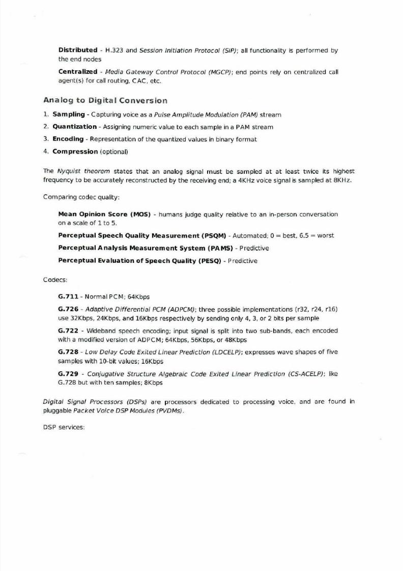
Analog to Digital Conversion
1. Sampling- Capturing voice as a Pulse Amplitude Modulation (PAM) stream
2. Quantization - Assigning numeric value to each sample in a PAM stream
3. Encoding - Representation of the quantized values in binary format
4. Compression (optional)
The Nyquist theorem states that an analog signal must be sampled at at least twice its highest
frequency to be accurately reconstructed by the receiving end; a 4KHz voice signal is sampled at 8KHz.
Comparing codec quality:
Mean Opinion Score (MOS) - humans judge quality relative to an in-person conversation
on a scale of 1 to 5.
Perceptual Speech Qua lity Measurement (PSQM) - Automated; 0 =best, 6.5 =worst
Perceptua l Analysis Measurement System (PAMS) - Predictive
Perceptual Evaluation of Speech Quality (PESQ) - Predictive
Codecs:
G.711 - Normal PCM; 64Kbps
G.726 -Adaptive Differential PCM (ADPCM); three possible implementations (r32, r24, r16)
use 32Kbps, 24Kbps, and 16Kbps respectively by sending only 4, 3, or 2 bits per sample
G.722 - Wideband speech encoding; input signal is split into two sub-bands, each encoded
with a modified version of ADPCM; 64Kbps, 56Kbps, or 48Kbps
G.728 - Low Delay Code Exited Linear Prediction (LDCELP); expresses wave shapes of five
samples with 10-bit values; 16Kbps
G. 729 - Conjugative Structure Algebraic Code Exited Linear Prediction (CS-ACELP); like
G.728 but with ten samples; 8Kbps
Digital Signal Processors (DSPs) are processors dedicated to processing voice, and are found in
pluggable Packet Voice DSP Modules (PVDMs).
DSP services:
8/6/2019 Ccnp Ont Notes (Ocr)
http://slidepdf.com/reader/full/ccnp-ont-notes-ocr 3/22
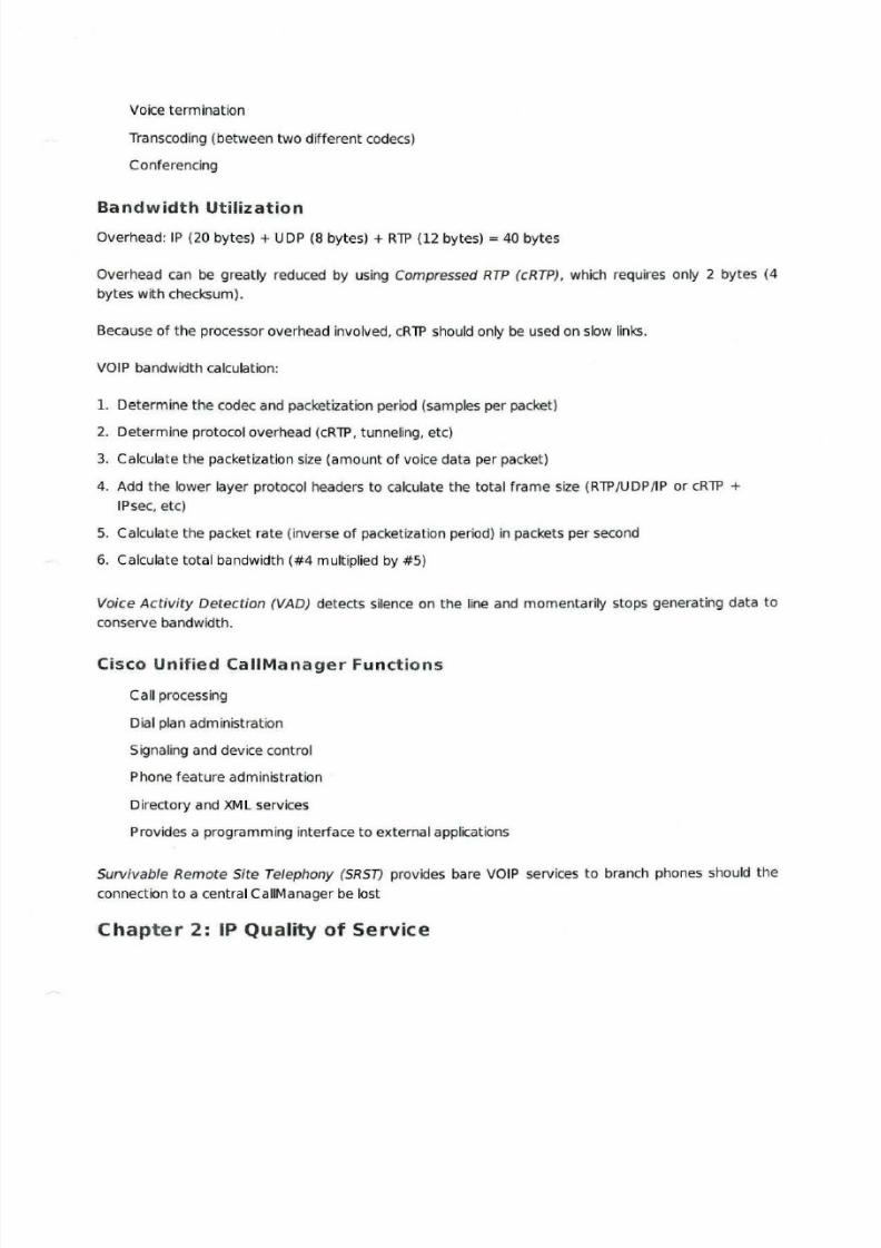
Voice termination
Transcoding (between two dif ferent codecs)
C onferencing
Bandwidth Utilization
Overhead: IP (20 bytes)+ UDP (8 bytes) + RTP (12 bytes)= 40 bytes
Overhead can be greatly reduced by using Compressed RTP (cRTP), which requires only 2 bytes {4
bytes with checksum ).
Because of the processor overhead involved, cRTP should only be used on slow links.
VOIP bandwidth calculation:
1. Determine the codec and packetization period (samples per packet)
2. Determine protocol overhead (cRTP, tunneling, etc)
3. Calculate the packetization size {amount of voice data per packet)
4. Add the lower layer protocol headers to calculate the total frame size (RTP/UDP/IP or cRTP +
IPsec, etc)
5. Calculate the packet rate (inverse of packetization period) in packets per second
6. Calculate total bandwidth (#4 multiplied by #5 )
Voice Activit y Detection (VAD) detects silence on the line and momentarily stops generating data to
conserve bandwidth.
Cisco Unified CaiiManager Fun ctions
Call processing
Dial plan administration
Signaling and device control
Phone feature administration
Directory and XML services
Provides a programming interface to external applications
Survivable Remote Site Telephony (SRST) provides bare VO IP services to branch phones should the
connection to a central CaiiManager be lost
Chapter 2: IP Quality of Service
8/6/2019 Ccnp Ont Notes (Ocr)
http://slidepdf.com/reader/full/ccnp-ont-notes-ocr 4/22
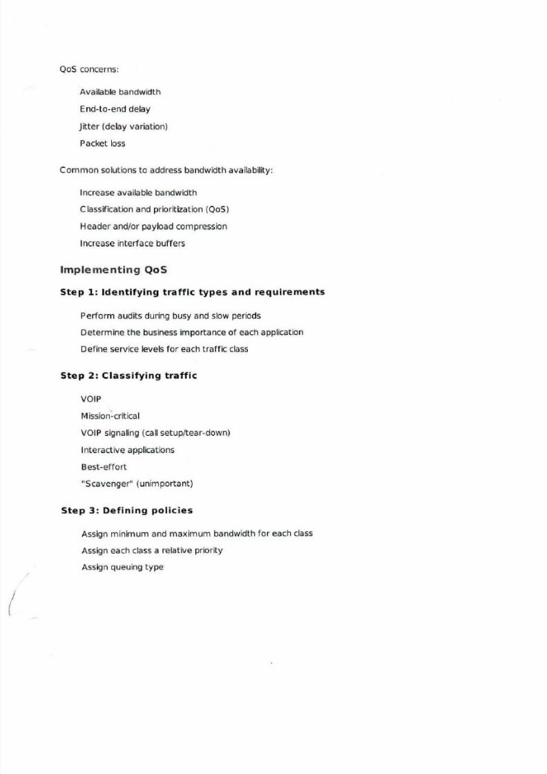
QoS concerns:
Available bandwidth
End-to-end delay
Jitter (delay variation)Packet loss
Common solutions to address bandwidth availability:
Increase available bandwidth
Classification and prioritization (QoS)
Header and/or payload compression
Increase interface buffers
Implementing QoS
Step 1: Identifying traffic types and requirements
Perform audits during busy and slow periods
Determine the business importance of each application
Define service levels fo r each traffic class
Step 2: Classifying traffic
VOIP
Mission-critical
VOIP signaling (call setup/tear-down)
Interactive applications
Best-effort
"Scavenger" (unimportant)
Step 3 : Defining policies
Assign minimum and maximum bandwidth fo r each class
Assign each class a relative priority
Assign queuing type
8/6/2019 Ccnp Ont Notes (Ocr)
http://slidepdf.com/reader/full/ccnp-ont-notes-ocr 5/22
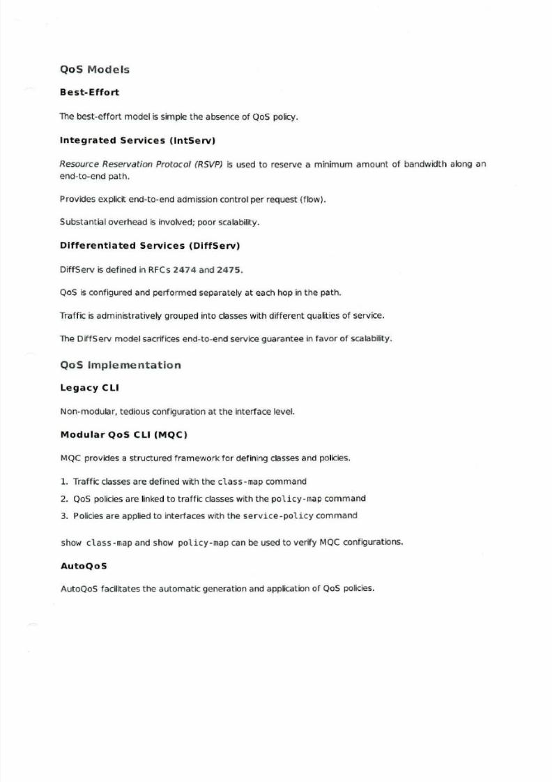
QoS Models
Best-Effort
The best-effort model is simple the absence of QoS policy.
Integrated Services (lntServ)
Resource Reservation Protocol (RSVP) is used to reserve a minimum amount of bandwidth along an
end-to-end path.
Provides explicit end-to-end admission control per request (flow).
Substantial overhead is involved; poor scalability.
Differentiated Services (DiffServ)
DiffServ is defined in RFCs 2474 and 2475.
QoS is configured and performed separately at each hop in the path.
Traffic is administratively grouped into classes with different qualities of service.
The DiffServ model sacrifices end-to-end service guarantee in favor of scalability.
QoS Implementation
Legacy CLI
Non-modular, tedious configuration at the interface level.
Modular QoS CLI (MQC)
MQC provides a structured framework fo r defining classes and policies.
1. Traffic classes are defined with the class -map command
2. QoS policies are linked to traffic classes with the policy-map command
3. Policies are applied to interfaces with the service-policy command
show class -map and show policy -map can be used to verify MQC configurations.
AutoQoS
AutoQoS facilitates the automatic generation and application of QoS policies.
8/6/2019 Ccnp Ont Notes (Ocr)
http://slidepdf.com/reader/full/ccnp-ont-notes-ocr 6/22
AutoQoS Discovery can perform automatic classification using NBAR and COP.
Perceived bandwidth must be configured accurately on interfaces with the bandwidth statement.
First generation AutoQoS is configured with auto qos voip on an interface, only automating QoS
configuration for VO IP traffic.
Modern (Enterprise) AutoQoS is configured with auto discovery qos to enable NBAR traffic analysis
and auto qos for policy construction.
SDM QoS Wizard
The SDM Wizard is a GU I frontend fo r QoS configuration using t hree built-in classes (VOIP. business
critica l, and best-effort) .
Allows fo r periodic monitoring of QoS performance.
Chapter 3: Classification, Marking, and NBAR
Marking should be performed as close to the source as possible.
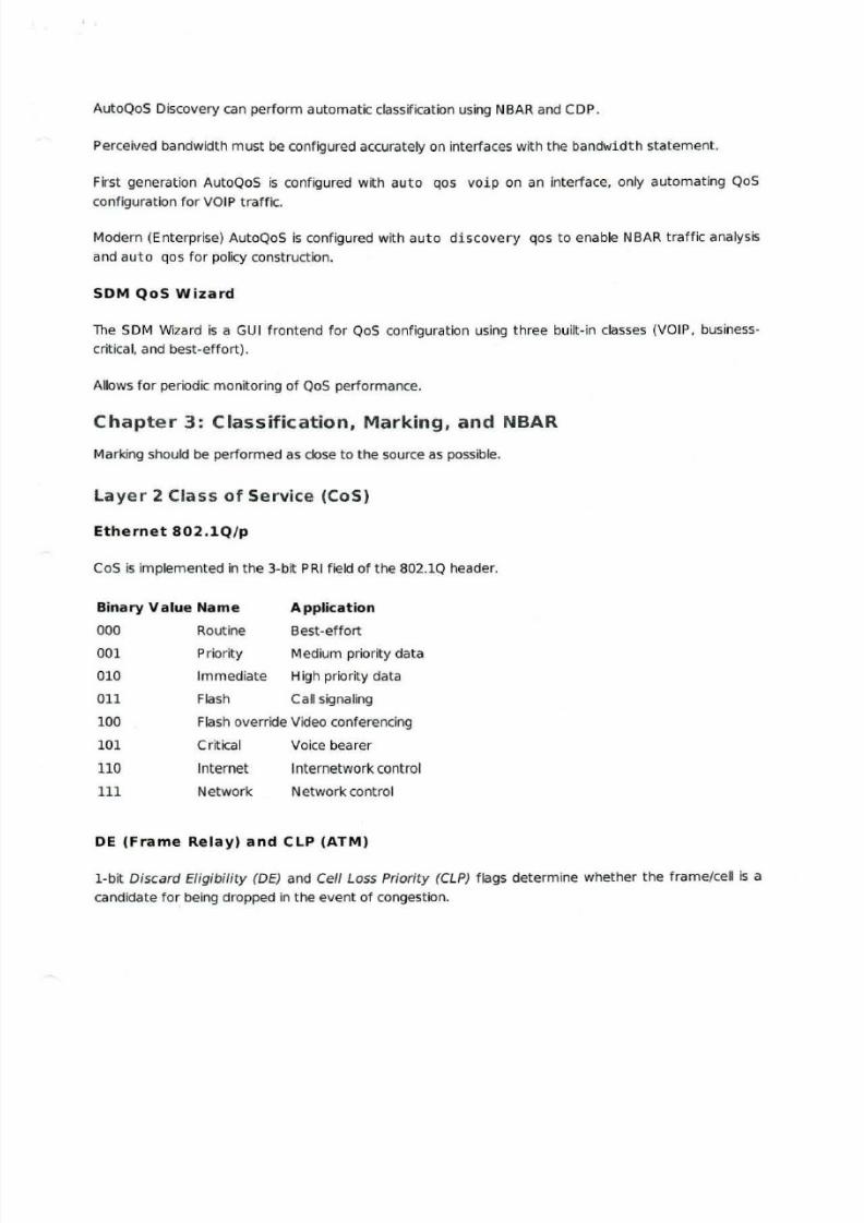
Layer 2 Class of Service (CoS)
Ethernet 802.1Q / p
CoS is implemented in the 3-bit PR I fie ld of the 802.10 header.
Bina ry Value Name Application
000 Rou tine Best-effort
001 Priority Medium priority data
010 Immediate High priority data
011 Flash Call signaling
100 Flash override Video conferencing
101 Critical Voice bearer
110 Internet Internetwork control
111 Network Network control
DE (Frame Relay) and CLP (ATM)
1-bit Discard El igibility (DE) and Cell Loss Priority (CLP) flags determ ine whether the frame/cell is a
candidate for being dropped in the event of congestion.
8/6/2019 Ccnp Ont Notes (Ocr)
http://slidepdf.com/reader/full/ccnp-ont-notes-ocr 7/22
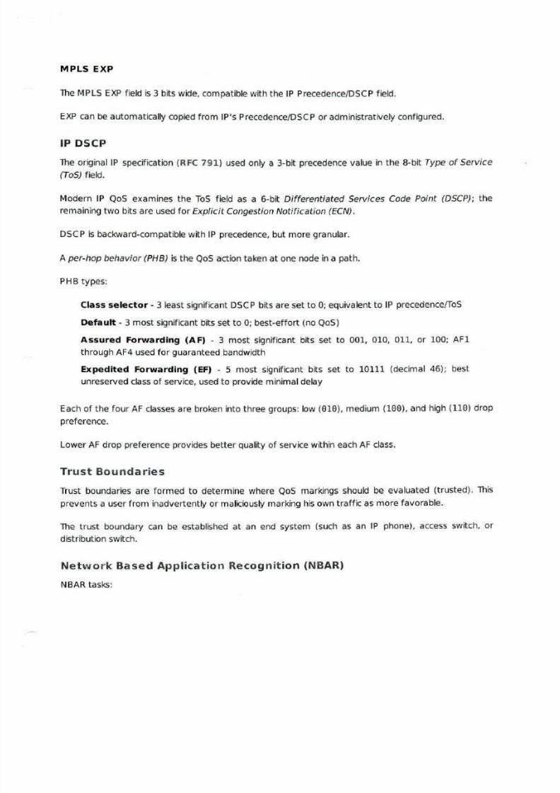
MPLS EXP
The MPLS EXP field is 3 bits wide, compatible with the IP Precedence/DSCP field.
EXP can be automatically copied from IP's Precedence/DSCP or administratively configured.
IP DSCP
The originaiiP specification (RFC 791) used only a 3-bit precedence value in the 8-bit Type of Service
(ToS) field.
Modern IP QoS examines the ToS field as a 6-bit Differentiated Services Code Point (DSCP); the
remaining two bits are used fo r Explicit Congestion Notification (ECN) .
DSC P is backward-compatible with IP precedence, but more granular.
A per-hop behavior (PHB) is the QoS action taken at one node in a path.
PHB types:
Class selector - 3 least significant DSCP bits are set to 0; equivalent to IP precedence/ToS
Default - 3 most significant bits set to 0; best-effort (no QoS )
Assured Forwarding (A F) - 3 most significant bits set to 001, 010, 011, or 100; AFl
through AF4 used fo r guaranteed bandwidth
Expedited Forwarding (EF) - 5 most significant bits set to 10111 (decimal 46); best
unreserved class of service, used to provide minimal delay
Each of the four AF classes are broken into three groups: low (010), medium (100), and high (110) drop
preference.
Lower AF drop preference provides better quality of service within each AF class.
Trust Boundaries
Trust boundaries are formed to determine where QoS markings should be evaluated (trusted). This
prevents a user from inadvertently or maliciously marking his own traffic as more favorable.
The trust boundary can be established at an end system (such as an IP phone), access switch, or
distribution switch.
Network Based Application Recognition (NBAR)
NBAR tasks:
8/6/2019 Ccnp Ont Notes (Ocr)
http://slidepdf.com/reader/full/ccnp-ont-notes-ocr 8/22
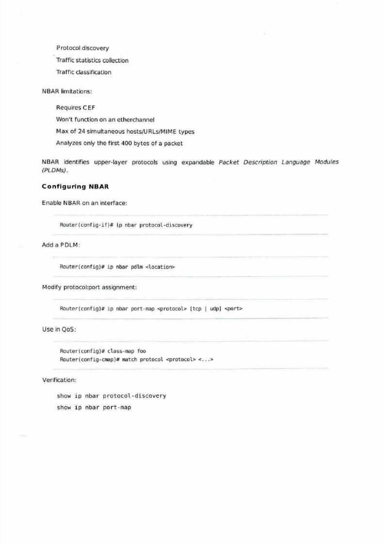
Protocol discovery
Traffic statistics collection
Traffic classification
NBAR limitations:
Requires CEF
Won't function on an etherchannel
Max of 24 simultaneous hosts/URLs/MIME types
Analyzes only the first 400 bytes of a packet
NBAR identif ies upper-layer protocols using expandable Packet Description Language Modules
(PLDMs).
Configu ring NBAR
Enable NBAR on an interface:
Router(config -if)# ip nba r protocol-discovery
Add a PDLM:
Router(config)# i p nbar pdlm <location>
Modify protocol:port assignment:
Router(config)# ip nbar port-map <protocol> [tcp 1 udp} <port>
Use in QoS:
Router(config)# class-map foo
Router(config-cmap)# match protocol <protocol>< .. .>
Verification:
show ip nbar protocol -discovery
show ip nbar port-map
8/6/2019 Ccnp Ont Notes (Ocr)
http://slidepdf.com/reader/full/ccnp-ont-notes-ocr 9/22
Chapter 4: Congestion Management and Queuing
The default queuing method on an interface faster than 2.048 Mbps is First In, First Out (FIFO).
Interfaces operating at 2.048 M bps or slower perform Weighted Fair Queuing (WFQ).
Each physical interface has hardware and software queuing mechanisms; software queues are only
used when the hardware queue is congested.
Tail-drop occurs when all queues are full and a packet is dropped.
Hardware queue sizes can be configured with tx- r ing- l imi t and verified with show contro11ers
<interface>.
Simple Queuing
First-In -F i rst -Out (FIFO)
Packets are transmitted in the order they are received with no preference (no QoS).
FI FO is the default mechanism fo r interfaces >2.048Mbps.
Priority Queuing (PQ)
PQ provides four queues: high, medium, no rma l. and low.
All packets in a higher priority queue will be processed before any packets in a lower priority queue.
Lower prior ity queues can be starved if higher priority queues consume all availab le bandwidth.
PQ is implemented by defining and applying priority lists:
Router(config)# priority-1ist 1 {interface 1 protoco1}
{high I medium I norma1 I 1ow}
Round Robin (RR)
All queues are equal priority; one packet is taken from each queue per cycle.
Round robin does not provide fo r traffic prioritization. and queues with larger packets will consume more
bandwidth than queues with smaller packets.
Weighted Round Robin (WRR)
WRR is a modification to RR which allows for disproportionate allowance of bandwidth to queues.
8/6/2019 Ccnp Ont Notes (Ocr)
http://slidepdf.com/reader/full/ccnp-ont-notes-ocr 10/22
Custom Queuing (CQ) is an example of WRR; it specifies a certain number of bytes to be processed
from each queue.
Weighted Fair Queuing
WFQ is the default mechanism on and only supported on interfaces less than or equal to 2.048 Mbps.
WFQ queues are created per flow and are not configurable.
Each flow is assigned to a dynamic FIFO queue by source/destination IP address, protocol number, ToS
value, or source/destination port number.
The maximum number of dynamic queues is configurable between 16- 4096 (256 by default).
Packets are dropped from aggressive flows more frequently than from less aggressive flows.
The hold queue is the sum of all memory available to the WFQ system; all packets are aggressively
dropped while the hold queue is full.
Each queue has a Congestive Discard Threshold (COT) which allows fo r early dropping of packets
before the queue is completely full.
WFQ can be disabled on an interface with no fair-queue (queuing is switched to FIFO).
Queue information can be viewed with show interface or show queue <interface>.
Class-Based Weighted Fair Queuing (CBWFQ)
CBWFQ is similar to WFQ but with user-defined queue classes instead of dynamically created flow-basedqueues.
CBWFQ supports a maximum of 64 queues.
Each queue is allotted a certain amount or percentage of the available bandwidth.
The default queue named c'lass -defau'l is always present and will match all traffic not matched by
other queues.
Bandwidth can be allocated in Kbps, percentage, or remaining percentage. All classes within a policy
map mustusethe
same unitof
measure (Kbpsor
percentage).
The default maximum reserved bandwidth is 75%; this can be modified with max-reserved -bandwidth
(applied to the interface).
Fair queuing (instead of FIFO) can be enabled fo r the default class with fair-queue followed by the
maximum number of dynamic queues.
8/6/2019 Ccnp Ont Notes (Ocr)
http://slidepdf.com/reader/full/ccnp-ont-notes-ocr 11/22
The queue size fo r each class can be adjusted with queue-limit.
Configuration example:
policy -map Foo
class Critical_Apps
bandwidth percent 20
queue -limit 50
class Normal_Apps
bandwidth remaining recent 50
class class-default
fair -queue 32
Low Latency Queuing (LLQ)
LLQ implements a strict-priority queue which is favored over all other queues.
LLQ is typically used for delay-sensitive traffic like VOIP.
The priority queue is policed to a certain bandwidth to prevent starvation of other queues.
Priority queues are created under a class with pr ior i ty <bandwidth> or pr ior i ty percent
<percentage>.
Configuration example:
policy -map Foo
class VOIP
priority 128
class Important_Stuff
bandwidth 512
queue -limit 100
class class-default
fair -queue 32
show policy-map [ interface] can be used to inspect policy maps.
Chapter 5: Congestion Avoidance, Policing, Shaping, and LinkEfficieny Mechanisms
Congestion avoidance is implemented to avoid tail drop, which occurs when there is no room left in a
queue fo r incoming packets.
8/6/2019 Ccnp Ont Notes (Ocr)
http://slidepdf.com/reader/full/ccnp-ont-notes-ocr 12/22
Ta il drop is not selective; less aggressive f lows are not preferred to aggressive f lows, thus no QoS can
be provided.
TCP global synchronization occurs when ta il dropping of packets forces flows to cycle between small
and large windows.
TCP starvation occurs when stateless protocols like uDP fi ll available queue space before the throttled
TCP flows.
Random Early Detection {RED)
When RED is implemented, packets are randomly dropped before the queue becomes full.
The rate of drop increases as the queues nears its maximum size.
RED mitigates the problem of TCP synchronization.
Configuration parameters:
Minimum threshold - Below this no packets are dropped
Maximum threshold - Above this all packets are dropped
Mark Probability Denominator (MPD) - An integer specifying the base probability of drop
Weighted Random Early Detection (WRED)
WRED is RED with the added capability of favoring prioritized traffic, based on the IP precedence or
DSCP.
Class-Based WRED (CBWRED)
CBWRED is WRED implemented inside a CBWFQ system.
CBWRED is applied to a CBWFQ class (under a policy map) with random-detect.
CBWRED operates on IP precedence by default but can be configured to evaluate DSCP.
Each precedence/DSCP value can be configured with a unique MPD and minimum and maximum
thresholds.
Configuration example:
policy-map Foo
c1ass Precedence_Based_WRED
8/6/2019 Ccnp Ont Notes (Ocr)
http://slidepdf.com/reader/full/ccnp-ont-notes-ocr 13/22
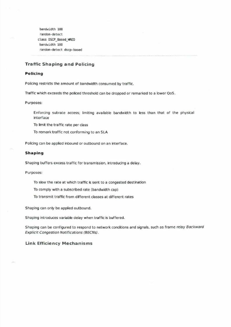
bandwidth 100
random-detect
class DSCP_Based_WRED
bandwidth 100
random-detect dscp-based
Traffic Shaping and Policing
Policing
Policing restricts the amount of bandwidth consumed by traffic.
Traffic which exceeds the po liced threshold can be dropped or remarked to a lower QoS.
Purposes:
Enforcing subrate access; limiting available bandwidth to less than that of the physical
interface
To limit the traffic rate per class
To remark traffic no t conforming to an SLA
Policing can be applied inbound or outbound on an interface.
Shaping
Shaping buffers excess traffic for transmission. introducing a delay.
Purposes:
To slow the rate at which traffic is sent to a congested destination
To comply with a subscribed rate (bandwidth cap)
To transmit traffic from dif ferent classes at different rates
Shaping can only be applied outbound.
Shaping introduces variable delay when traffic is buffered.
Shaping can be configured to respond to network conditions and signals, such as frame relay Backward
Explicit Congestion Notifications (BECNs).
Link Efficiency Mechanisms
8/6/2019 Ccnp Ont Notes (Ocr)
http://slidepdf.com/reader/full/ccnp-ont-notes-ocr 14/22
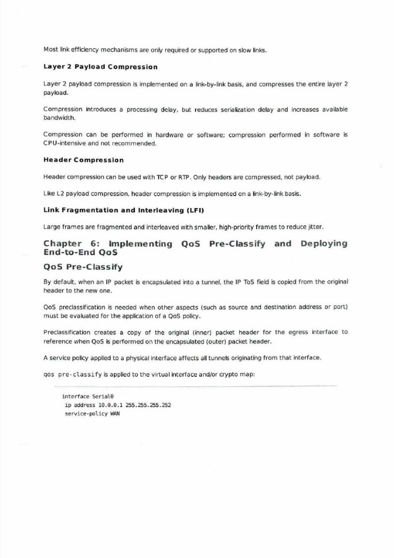
Most link efficiency mechanisms are only required or supported on slow links.
Layer 2 Payload Compression
Layer 2 payload compression is implemented on a link-by-link basis, and compresses the entire layer 2
payload.
Compression introduces a processing delay, but reduces serialization delay and increases available
bandwidth.
Compression can be performed in hardware or so ftware; compression performed in software is
CPU-intensive and not recommended.
Header Compression
Header compression can be used with TCP or RlP. Only headers are compressed, not payload.
Like L2 payload compression, header compression is implemented on a link-by-link basis.
Link Fragmentation and Interleaving (LFI)
Large frames are fragmented and interleaved with sma ller, high-priority frames to reduce jitter.
Chapter 6: Implementing QoS Pre -Classify and DeployingEnd-to-End QoS
QoS Pre-Classify
By default. when an IP packet is encapsulated into a tunnel, the IP ToS field is copied from the originalheader to the new one.
QoS preclassification is needed when other aspects (such as source and destination address or port)
must be evaluated for the application of a QoS policy.
Preclassification creates a copy of the original (inner) packet header for the egress interface to
reference when QoS is performed on the encapsulated (outer) packet header.
A service policy applied to a physical interface affects all tunnels originating from that interface.
qos pre-c1ass i fy is applied to the virtual interface and/or crypto map:
interface SerialO
ip address 10.0.0.1 255.255.255.252
service-policy WAN
8/6/2019 Ccnp Ont Notes (Ocr)
http://slidepdf.com/reader/full/ccnp-ont-notes-ocr 15/22
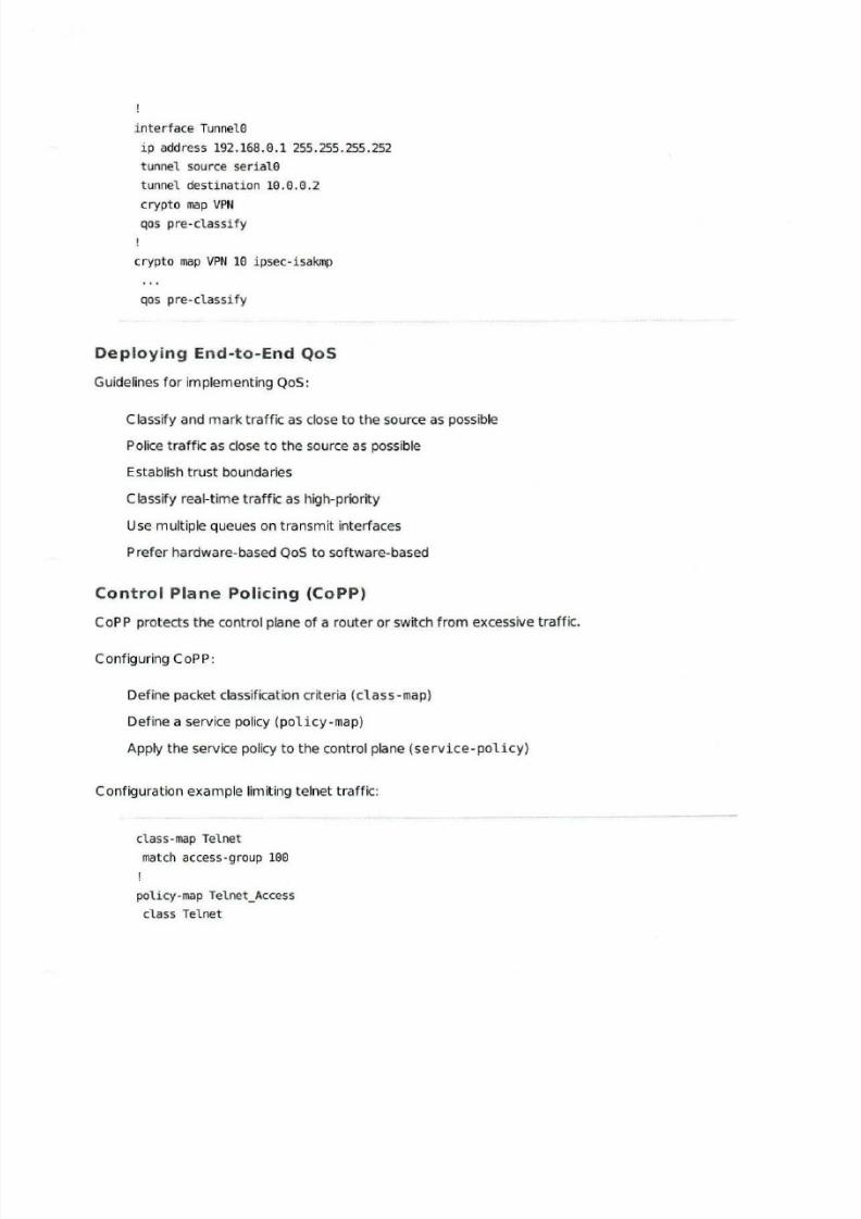
interface Tunne10
ip address 192.168.0.1 255.255.255.252
tunnel source seria10
tunnel destination 10.0.0.2
crypto map VPN
qos pre-classify
crypto map VPN 10 ipsec-isakmp
qos pre-classi fy
Deploying End-to-End QoS
Guidelines fo r implementing QoS:
Classify and mark traffic as close to the source as possible
Police traffic as close to the source as possible
Establish trust boundaries
Classify real-time traffi c as high-priority
Use multiple queues on transmit interfaces
Prefer hardware-based QoS to software-based
Control Plane Policing (CoPP)
CoP P protects the control plane of a router or switch from excessive traffic.
Configuring CoP P:
Define packet classification criteria (class-map)
Define a service policy (policy-map)
Apply the service policy to the control plane (service -pol icy)
Configuration example limiting te lnet traffic:
class-map Te1net
match access-group 100
po1icy-map Te1net_Access
c1ass Te1net
8/6/2019 Ccnp Ont Notes (Ocr)
http://slidepdf.com/reader/full/ccnp-ont-notes-ocr 16/22
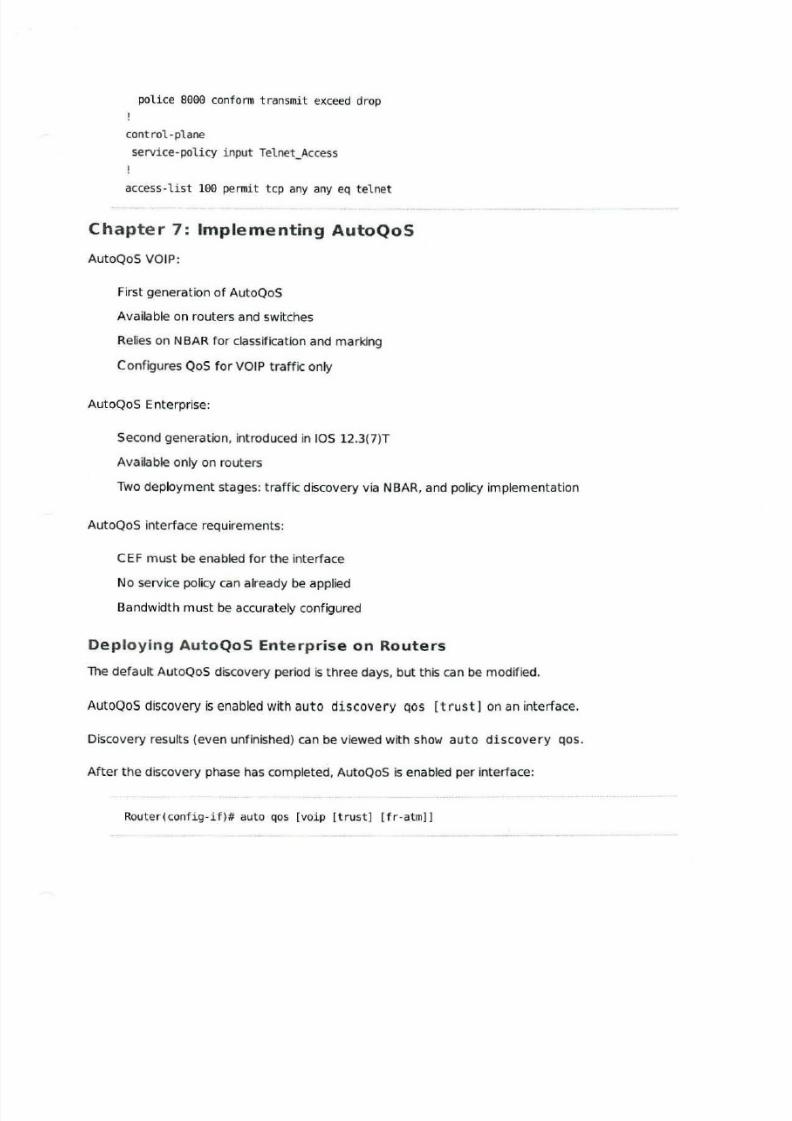
police 8000 conform transmit exceed drop
cont ro1-plane
servi ce-policy input Telnet_Access
access-list 100 permit tcp any any eq telnet
Chapter 7: Implementing AutoQoS
AutoQoS VO IP:
First generation of AutoQoS
Available on routers and switches
Relies on NBAR fo r classification and marking
Configures QoS fo r VOIP traffic only
Aut oQoS Enterprise:
Second generation, introduced in lOS 12.3(7)T
Available only on routers
Two deployment stages: traffic discovery via NBAR, and policy implementation
AutoQoS interface requirements:
CEF must be enabled for the interface
No service policy can already be applied
Bandwidth must be accurately configured
De ploying AutoQoS Enterprise on Routers
The default AutoQoS discovery period is three days, but this can be modified.
AutoQoS discovery is enabled with auto discovery qos [ t rust) on an interface.
Discovery results (even unfinished) can be viewed with show auto discovery qos.
After the discovery phase has completed, AutoQoS is enabled per interface:
Router(config-if)# auto qos [voip (trust) [fr-atm)]
8/6/2019 Ccnp Ont Notes (Ocr)
http://slidepdf.com/reader/full/ccnp-ont-notes-ocr 17/22
The voip keyword forces legacy AutoQoS (VOIP only).
Verification:
show au to qos - Displays the auto-generated AutoQoS class and policy maps
show policy-map interface - Displays applied policy map and QoS parameters for eachinterface
Deploying AutoQoS VOIP on Switches
To configure a port as trusted only when a trusted device is detected, such as a Cisco IP phone (requires
CDPv2):
Switch(config-if)# auto qos voip cisco-phone
To enable a permanently trusted interface (for example, a trunk or uplink):
Switch(config-if)# auto qos voip trust
The default CoS-to-DSCP mappings can be modified with m'ls qos map.
Verification:
show auto qos- Displays the auto-generated AutoQoS configuration
show m'ls qos interface <interface>- Displays QoS parameters fo r an interface
show mls qos maps- Displays the CoS-to-DSCP mappings used by AutoQoS
Common AutoQoS Issues
Too many classes are created
The configuration generated by AutoQoS doesn't automatically adjust to changing network
conditions
Even with auto discovery, AutoQoS may not fi t some scenarios
Chapter 8: Wireless LAN
QoSImplementat
ion
Wireless LANs use Carrier Sense Multiple Access with Collision Avoidance (CSMAJCA) as the MAC
mechanism.
Collision avoidance is performed by Distributed Coordinated Function (DCF), which employs
Inter-Frame Spacing (IFS) and random back-off windows to minimize collisions.
8/6/2019 Ccnp Ont Notes (Ocr)
http://slidepdf.com/reader/full/ccnp-ont-notes-ocr 18/22
Wireless LAN QoS
WLAN QoS is defined in IEEE 802.1le.
Wireless Multimedia (WMM) was released prior to 802.11e as an interim standard.
WM M provides four access categories, or queues:
Platinum - Voice
Gold - Video
Silver- Best effort (default)
Bronze - Background
802.11e provides eight priority levels. 0 through 7.
802.1le priorities can be mapped to WMM access categories for backward compatibility:
WMM 802. l le
Platinum 6 and 7
Gold 4 and 5
Silver 0 and 3
Bronze 1 and 2
802.11e and WMM use Enhanced DCF (EDCF) to provide proportional back-off window sizes fo r each
class.
Split-MAC Architecture
The split-MAC architecture separates MAC services to real-time and non-real-t ime functions.
Real-time functions are performed by Lightweight Access Points (LAPs):
Beacon generation
Probe transmission/response
Power management
802.1le/WMM QoS
Encryption/decryption
Control frame processing
Packet buffering
8/6/2019 Ccnp Ont Notes (Ocr)
http://slidepdf.com/reader/full/ccnp-ont-notes-ocr 19/22
Non-real-time functions are handled by a centralized Wireless LAN Controller (WLC):
Client association/disassociation
802.lle/WMM resource reservation
802.1x EAP
Key management
Lightweight Access Point Protocol (LWAPP) provides tunneling between LAPs and a WLC.
802.1le!WMM QoS values are translated to DSCP values on the LWAPP packet header to ensure
end-to-end QoS.
Chapter 9: 802. lx and Configuring Encryption andAuthentication
Wireless Security
Wired Equivalent Privacy (WEP) was the first implementation of wireless encryption. and has several
drawbacks:
Weak encryption (proven to be easily broken)
Vulnerable to dictionary attacks
Does not offer protection against rogue access points
Keys must be manually dis tributed
Cisco developed Lightweight Extensible Authentication Protocol (LEAP) to extend WEP.
LEAP provides several benefits:
Server-based authentication using 802.1x
Dynamic keys
Mutual client and server authentication
Replay attack protection
Wi-Fi Protected Access (WPA) was developed by the Wi-F i Alliance Group as an interim non-proprietarysolution to replace WEP.
IEEE 802.l l i (also known as WPA2) was released afte r WPA, but required a hardware upgrade to
implement the stronger AES encryption.
8/6/2019 Ccnp Ont Notes (Ocr)
http://slidepdf.com/reader/full/ccnp-ont-notes-ocr 20/22
IEEE 802 . lx802.1x provides port-based network access control.
802.lx is used in conjunction with Extensible Authentication Protocol (EAP) to secure wireless LANs.
EAP Authentication Protocols
Cisco LEAP
Provides fast and secure roaming and single sign-on.
EAP-FAST
EAP Flexible Authentication via Secure Tunneling (EAP-FAST) is nonproprietary.
EAP-FAST does not require certificates.
EAP -FASTconsists of three phases:
Phase 0 (optional) - Client is dynamically provisioned with a Protected Access Credential
(PAC)
Phase 1 - Client establishes a secure tunnel with the AAA server using PAC
Phase 2 - Client authentication
EAP-TLS
EAP Transport LayerSecurity (EAP-TLS) uses l lS and PK I.
Clients and servers must have certificates to be authenticated.
PEAP
Protected EAP (PEAP) only requires the authentication server to have a certificate.
PEAP has two phases:
Phase 1 - The server is authenticated and an encrypted tunnel is formed
Phase 2 - Client authentication
Client authentication can be performed using Generic Token Card (GTC) (ca lled PEAP-GTC) or
Microsoft Challenge Handshake Authentication Protocol (MS-CHAP) version 2 (PEAP-MSC HAPv2).
8/6/2019 Ccnp Ont Notes (Ocr)
http://slidepdf.com/reader/full/ccnp-ont-notes-ocr 21/22
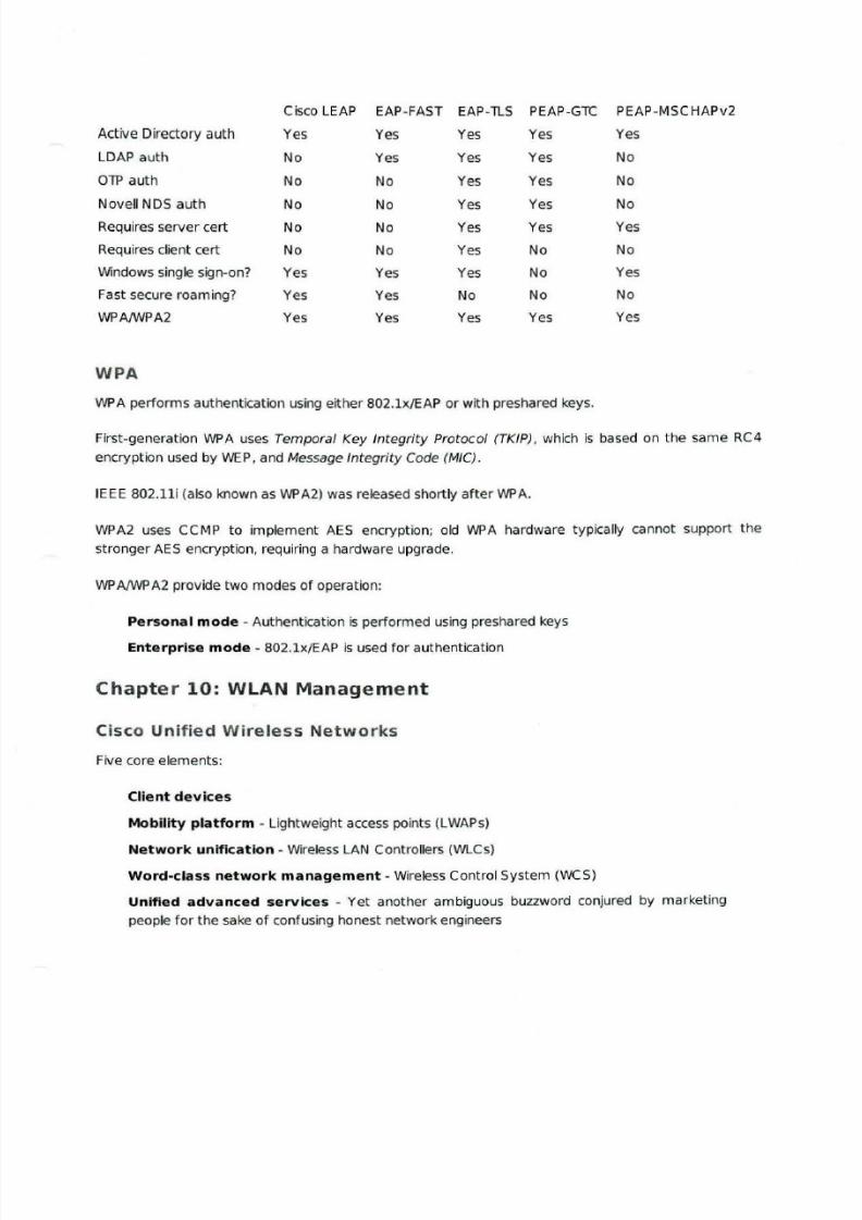
Cisco LEAP EAP -FAST EAP -lLS PEAP-GTC PEAP-MSCHAPv2
Active Directory auth Yes Yes Yes Yes Yes
LDAP auth No Yes Yes Yes No
OTP auth No No Yes Yes No
Novell NOS auth No No Yes Yes No
Requ ires server cert No No Yes Yes Yes
Requires client cert No No Yes No No
Windows single sign-on? Yes Yes Yes No Yes
Fast secure roaming? Yes Yes No No No
WPA/WPA2 Yes Yes Yes Yes Yes
WPA
WPA performs authentication using either 802.lx/EAP or with preshared keys.
First-generation WPA uses Temporal Key Integrity Protocol (TKIP), which is based on the same RC4
encryption used by WEP, and Message Integrity Code (MIC).
IEEE 802.11i (also known as WPA2) was released shortly after WPA.
WPA2 uses CC MP to implement AES encryption; old WPA hardware typically cannot support the
stronger AES encryption, requiring a hardware upgrade.
WP A/WPA2 provide two modes of operation:
Personal mode - Authentication is performed using preshared keys
Ente rprise mode - 802.1x/EAP is used fo r authentication
Chapter 10: WLAN Management
Cisco Unified Wireless Networks
Five core elements:
Client dev ices
Mobility platform - Lightweight access points (LWAPs)
Network unification - Wireless LAN Controllers (WLCs)
Word-class network management - Wireless Control System (WCS)
Unified advanced services - Yet another am biguous buzzword conjured by marketing
people for the sake of confusing honest network engineers
8/6/2019 Ccnp Ont Notes (Ocr)
http://slidepdf.com/reader/full/ccnp-ont-notes-ocr 22/22
LWAPs include the 1500, 1300, 1240AG, 1230AG, 1130AG, and 1000 models.
WLCs include the 4400 and 2000 models, as well as the Catalyst 6500 Wireless Services Module (WSM)
and ISR and Catalyst 3750 integration.
WLAN Imp lementation
Wireless LANs can be implemented with either autonomous or lightweight access points :
Autonomous APs - Each AP is independently configured and monitored
Lightweight APs - Configuration and monitoring is centralized on a WLC
A Wireless LAN Solution Engine (WLSE) and Wireless Domain Services (WDS) server can be used to
provide centralized management of autonomous APs .
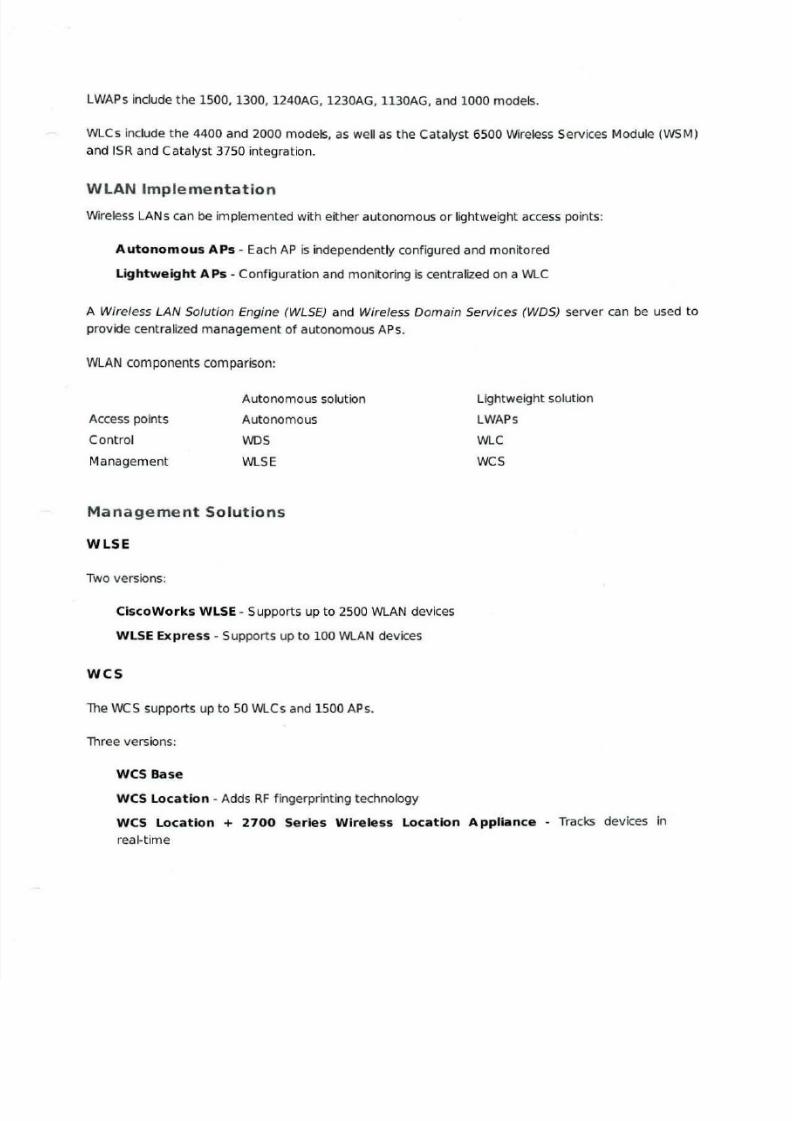
WLAN components comparison:
Access points
Control
Management
Autonomous solution
Autonomous
WDS
WLSE
Management So lutions
WLSE
Two versions:
CiscoWorks WLSE - Supports up to 2500 WLAN devices
WLSE Express - Supports up to 100 WLAN devices
wcs
The WCS supports up to 50 WLCs and 1500 APs.
Three versions:
WCS Base
WCS Location - Adds RF f ingerprinting technology
Lightweight solution
LWAPs
WLC
wcs
WCS Location + 2700 Series Wireless Location Appliance - Tracks devices in
real-time