Embed Size (px)
DESCRIPTION
CCI1311-V1-2-Book2-Lab
Citation preview

Hitachi Enterprise Hardware and Software Fundamentals CCI1311 Book 2 of 2
Courseware Version 1.2
Page ii HDS Confidential: For distribution only to authorized parties.
Notice: This document is for informational purposes only, and does not set forth any warranty, express or implied, concerning any equipment or service offered or to be offered by Hitachi Data Systems. This document describes some capabilities that are conditioned on a maintenance contract with Hitachi Data Systems being in effect, and that may be configuration-dependent, and features that may not be currently available. Contact your local Hitachi Data Systems sales office for information on feature and product availability.
Hitachi Data Systems sells and licenses its products subject to certain terms and conditions, including limited warranties. To see a copy of these terms and conditions prior to purchase or license, please call your local sales representative to obtain a printed copy. If you purchase or license the product, you are deemed to have accepted these terms and conditions.
THE INFORMATION CONTAINED IN THIS MANUAL IS DISTRIBUTED ON AN "AS IS" BASIS WITHOUT WARRANTY OF ANY KIND, INCLUDING WITHOUT LIMITATION, ANY IMPLIED WARRANTIES OF MERCHANTABILITY, FITNESS FOR A PARTICULAR PURPOSE OR NONINFRINGEMENT. IN NO EVENT WILL HDS BE LIABLE TO THE END USER OR ANY THIRD PARTY FOR ANY LOSS OR DAMAGE, DIRECT OR INDIRECT, FROM THE USE OF THIS MANUAL, INCLUDING, WITHOUT LIMITATION, LOST PROFITS, BUSINESS INTERRUPTION, GOODWILL OR LOST DATA, EVEN IF HDS EXPRESSLY ADVISED OF SUCH LOSS OR DAMAGE.
Hitachi Data Systems is registered with the U.S. Patent and Trademark Office as a trademark and service mark of Hitachi, Ltd. The Hitachi Data Systems logotype is a trademark and service mark of Hitachi, Ltd.
The following terms are trademarks or service marks of Hitachi Data Systems Corporation in the United States and/or other countries:
Hitachi Data Systems Registered Trademarks Hi-Track ShadowImage TrueCopy Hitachi Data Systems Trademarks Essential NAS Platform HiCard HiPass Hi-PER Architecture Hi-Star Lightning 9900 Lightning 9980V Lightning 9970V Lightning 9960 Lightning 9910 NanoCopy Resource Manager SplitSecond Thunder 9200 Thunder 9500 Thunder 9585V Thunder 9580V Thunder 9570V Thunder 9530V Thunder 9520V Universal Star Network Universal Storage Platform
All other trademarks, trade names, and service marks used herein are the rightful property of their respective owners.
NOTICE:
Notational conventions: 1KB stands for 1,024 bytes, 1MB for 1,024 kilobytes, 1GB for 1,024 megabytes, and 1TB for 1,024 gigabytes, as is consistent with IEC (International Electrotechnical Commission) standards for prefixes for binary and metric multiples.
©2009, Hitachi Data Systems Corporation. All Rights Reserved
HDS Academy 0019
Contact Hitachi Data Systems at www.hds.com.

HDS Confidential: For distribution only to authorized parties. Page iii
Product Names mentioned in courseware: Enterprise Storage Systems
Hitachi Universal Storage Platform™ V Hitachi Universal Storage Platform™ VM Hitachi Universal Storage Platform™ Hitachi Network Storage Controller
Legacy Products: Hitachi Lightning 9900™ Series enterprise storage systems Hitachi Lightning 9900™ Series enterprise storage systems
Modular Storage Systems Hitachi Adaptable Modular Storage Hitachi Workgroup Modular Storage Hitachi Simple Modular Storage Hitachi Adaptable Modular Storage 2000 Family
Legacy Products: Hitachi Thunder 9500™ Series modular storage systems Hitachi Thunder 9200V™ entry-level storage
Management Tools Hitachi Basic Operating System Hitachi Basic Operating System V Hitachi Resource Manager™ utility package
Module Volume Migration Software LUN Manager/LUN Expansion Network Data Management Protocol (NDMP) agents Logical Unit Size Expansion (LUSE) Cache Partition Manager feature Cache Residency Manager feature Storage Navigator program Storage Navigator Modular program Storage Navigator Modular 2 program
Replication Software Remote Replication:
Hitachi Universal Replicator software Hitachi TrueCopy® Heterogeneous Remote Replication software bundle Hitachi TrueCopy® Remote Replication software bundle (for modular systems) Hitachi TrueCopy® Synchronous software Hitachi TrueCopy® Asynchronous software Hitachi TrueCopy® Extended Distance software

Page iv HDS Confidential: For distribution only to authorized parties.
In-System Replication: Hitachi ShadowImage® Heterogeneous Replication software (for enterprise systems) Hitachi ShadowImage® Replication software (for modular systems) Hitachi Copy-on-Write Snapshot software
Hitachi Storage Command Software Suite Hitachi Chargeback software Hitachi Device Manager software Hitachi Dynamic Link Manager software Hitachi Global Link Availability Manager software Hitachi Global Reporter software Hitachi Path Provisioning software Hitachi Protection Manager software Hitachi QoS for File Servers software Hitachi QoS for Oracle software Hitachi Replication Monitor software Hitachi Storage Services Manager software Hitachi Storage Services Manager software Hitachi Tiered Storage Manager software Hitachi Tuning Manager software Hitachi Resource Manager™ utility package Hitachi Data Retention Utility Hitachi Performance Monitor feature Hitachi Volume Shredder software
Other Software Hitachi Backup and Recovery software, powered by CommVault® Hitachi Backup Services Manager software, powered by APTARE® Hitachi Business Continuity Manager software Hitachi Command Control Interface (CCI) Software Hitachi Dynamic Provisioning software Hitachi Storage Resource Management Solutions Hitachi Volume Migration software Hi-Track® Monitor
Other Solutions and Terms Hitachi Content Archive Platform Hitachi Essential NAS Platform™ Hitachi High-performance NAS Platform, powered by BlueArc® Hi-Star™ crossbar switch architecture Hitachi Universal Star Network™ V

Contents Book 1 of 2
INTRODUCTION.............................................................................................................XI
1. HARDWARE OVERVIEW ........................................................................................... 1-1
2. HITACHI BASIC OPERATING SYSTEM........................................................................ 2-1
3. HITACHI UNIVERSAL VOLUME MANAGER SOFTWARE................................................. 3-1
4. HITACHI SHADOWIMAGE® HETEROGENEOUS REPLICATION SOFTWARE AND COPY-ON-WRITE SNAPSHOT SOFTWARE ............................................................... 4-1
5. HITACHI DYNAMIC PROVISIONING SOFTWARE ........................................................... 5-1
6. HITACHI TRUECOPY® HETEROGENEOUS REMOTE REPLICATION SOFTWARE .............. 6-1
Book 2 of 2
7. HITACHI UNIVERSAL REPLICATOR SOFTWARE .......................................................... 7-1 Module Objectives ...................................................................................................................7-1 Primary Functions ....................................................................................................................7-2 Key Features............................................................................................................................7-3 How Universal Replicator Software Works............................................................................7-10 Configurations........................................................................................................................7-16 Universal Replicator Software Configurations .......................................................................7-17 Volume Specifications............................................................................................................7-19 Pair Status Transition.............................................................................................................7-21 Pair Volume Status: Volume Status Conditions ....................................................................7-22 Pair Volume Status Conditions ..............................................................................................7-24 Volume Status Conditions .....................................................................................................7-25 Pair Volume Status ................................................................................................................7-26 Preparation for Operations ....................................................................................................7-27 Overview of Commands.........................................................................................................7-29 Commands — Paircreate Overview ......................................................................................7-30 Paircreate — S-VOL Input .....................................................................................................7-31 Paircreate — Configure Journal Groups................................................................................7-32 Paircreate — Details ..............................................................................................................7-33 Commands — PairCreate Set/Apply .....................................................................................7-34 Commands.............................................................................................................................7-35 Pairsplit –r ..............................................................................................................................7-38 Pairresync ..............................................................................................................................7-41 Pairresync Options.................................................................................................................7-42 Pairresync ..............................................................................................................................7-44 Deleting a Pair .......................................................................................................................7-45 Deleting a Pair: ......................................................................................................................7-46 Deleting a Pair .......................................................................................................................7-48 Monitoring Pair Operations ....................................................................................................7-49 Usage Monitor Components ..................................................................................................7-50 Usage Monitor........................................................................................................................7-51 Review of Components..........................................................................................................7-58

Hitachi Enterprise Hardware and Software Fundamentals Contents
Page vi HDS Confidential: For distribution only to authorized parties.
8. VIRTUAL PARTITION MANAGER SOFTWARE...............................................................8-1 Module Objectives................................................................................................................... 8-1 Overview.................................................................................................................................. 8-2 Storage Logical Partition ......................................................................................................... 8-6 Cache Logical Partition ........................................................................................................... 8-8 Access Roles......................................................................................................................... 8-10 Supported Functions for SPA................................................................................................ 8-11 Concept ................................................................................................................................. 8-12 Storage Administrator and Storage Partition Administrator .................................................. 8-13 Features ................................................................................................................................ 8-21 Configuration Change ........................................................................................................... 8-24 Control ................................................................................................................................... 8-26 Best Practices........................................................................................................................ 8-28 Virtual Partition Manager Best Practices............................................................................... 8-30 Operations ............................................................................................................................. 8-31 Functions ............................................................................................................................... 8-32 Creating an SLPR ................................................................................................................. 8-33 Migrating Resources in an SLPR .......................................................................................... 8-35 Creating a CLPR ................................................................................................................... 8-37 Creating SLPR and CLPR Summary .................................................................................... 8-40 Deleting a CLPR.................................................................................................................... 8-41 Deleting an SLPR.................................................................................................................. 8-42 SLPR and CLPR User IDs .................................................................................................... 8-43 Program Products (PP) Licensing Type................................................................................ 8-45 PP Licensing Scheme ........................................................................................................... 8-46 License Key Partition Definition............................................................................................. 8-47
9. DATA RETENTION UTILITY OVERVIEW.......................................................................9-1 Module Objectives................................................................................................................... 9-1 Overview.................................................................................................................................. 9-2 Accessing ................................................................................................................................ 9-4 Graphical User Interface ......................................................................................................... 9-5 Restrictions for Logical Volumes............................................................................................. 9-8 Access Attribute....................................................................................................................... 9-9 Expiration Lock...................................................................................................................... 9-10 Term Setting.......................................................................................................................... 9-11 Changing Access Attributes .................................................................................................. 9-12
10. MAINFRAME CONSIDERATIONS.............................................................................10-1 Module Objectives................................................................................................................. 10-1 Mainframe Compatibility........................................................................................................ 10-2 Business Continuity Manager................................................................................................ 10-3 Dataset Replication for IBM z/OS.......................................................................................... 10-4 Database Replication of IBM z/OS........................................................................................ 10-5 Compatible Mirroring for IBM FlashCopy .............................................................................. 10-6 Universal Storage Platform V Mainframe Compatibility ........................................................ 10-7 IBM and Hitachi ..................................................................................................................... 10-8 SATA Storage for DFSMShsm ML1..................................................................................... 10-9 SATA Storage for Tivoli....................................................................................................... 10-10 VTF™ Mainframe Benefits .................................................................................................. 10-11
11. HITACHI STORAGE COMMAND SUITE ....................................................................11-1 Module Objectives................................................................................................................. 11-1 Storage Management Command Suite................................................................................. 11-2 Common Software Management Framework ....................................................................... 11-4 Single Sign On and Role Based Permissions ....................................................................... 11-5 Integration with the Dashboard ............................................................................................. 11-6
Hitachi Enterprise Hardware and Software Fundamentals Contents
HDS Confidential: For distribution only to authorized parties. Page vii
Data and Host Agent Integration ...........................................................................................11-7 Element Management Software — A Layered Approach......................................................11-8 Device Manager Software — Foundation for Higher Level Capabilities ...............................11-9 Device Manager Software and Resource Manager Software .............................................11-11 Device Manager Software— Solution to Complex Challenges ...........................................11-12 Device Manager Software Purpose.....................................................................................11-13 Device Manager Business Agility ........................................................................................11-14 Device Manager Capabilities ...............................................................................................11-15 Link and Launch Operations................................................................................................11-16 Device Manager Configuration Operations .........................................................................11-17 Device Manager Components .............................................................................................11-18 Provisioning Manager ..........................................................................................................11-19 Provisioning Manager Host Volume Management ..............................................................11-21 Preparation to Start Software Operations............................................................................11-22 Add Storage Systems ..........................................................................................................11-23 Add Host ..............................................................................................................................11-26 LUN Scan Operation............................................................................................................11-28 LUN Scan.............................................................................................................................11-29 Storage Management ..........................................................................................................11-32 My Groups ...........................................................................................................................11-33 User Account Management .................................................................................................11-37 Sample LUN Security...........................................................................................................11-39 Configuring LUN Security (Add Storage Wizard) ................................................................11-40 Device Manager Reporting ..................................................................................................11-41 Command Line Interface (CLI) ............................................................................................11-42 Tuning Manager Software ...................................................................................................11-43 The Performance Management Challenge without Tuning Manager Software...................11-44 Introducing Tuning Manager Software.................................................................................11-45 Centralized Performance and Capacity Management.........................................................11-46 Types of Data Collected by Tuning Manager ......................................................................11-47 Resources That Can Be Monitored .....................................................................................11-48 Components.........................................................................................................................11-49 Agents..................................................................................................................................11-51 Positioning ...........................................................................................................................11-52 High-level Architecture.........................................................................................................11-53 Data Collection Basics for Monitoring Arrays ......................................................................11-55 Data Collection Basics for Monitoring Hosts, Switches, and Databases.............................11-56 Server Architecture ..............................................................................................................11-57 First Login ............................................................................................................................11-59 Main Screen Layout of GUI .................................................................................................11-60 Main Screen GUI Layout .....................................................................................................11-61 V6.0 GUI Overview ..............................................................................................................11-62 Global Task Bar ...................................................................................................................11-63 Application Bar Area ............................................................................................................11-64 Explorer and Navigation Area..............................................................................................11-69 Explorer and Navigation Area..............................................................................................11-71 Link Management Software .................................................................................................11-72 Dynamic Link Manager Software.........................................................................................11-73 Global Link Manager Software ............................................................................................11-75 Dynamic Link Manager Software Features .........................................................................11-77 Global Link Manager Software Features .............................................................................11-78 Without Global Link Manager Software ...............................................................................11-86 With Global Link Manager Software ....................................................................................11-87 Dynamic Link Manager Software and Global Link Manager Working Together..................11-88 Global Link Manager Software Architecture ........................................................................11-89

Hitachi Enterprise Hardware and Software Fundamentals Contents
Page viii HDS Confidential: For distribution only to authorized parties.
12. HITACHI STORAGE COMMAND SUITE ....................................................................12-1 Tiered Storage Manager Software ........................................................................................ 12-2 Product Description ............................................................................................................... 12-3 Product Position .................................................................................................................... 12-4 Device Manager Compared .................................................................................................. 12-5 Technical Focus and Value ................................................................................................... 12-6 Entities Definition................................................................................................................... 12-7 Organizational Definitions ..................................................................................................... 12-8 Graphical User Interface ....................................................................................................... 12-9 Basic Functions ................................................................................................................... 12-10 Migrating Data ..................................................................................................................... 12-11 Standard Workflow .............................................................................................................. 12-12 Create Storage Domain....................................................................................................... 12-13 Create Domain .................................................................................................................... 12-14 Created Domain .................................................................................................................. 12-15 Search Attributes................................................................................................................. 12-16 Filtering or Searching Volumes ........................................................................................... 12-17 Searching Volumes ............................................................................................................. 12-18 Create Storage Tier............................................................................................................. 12-19 Create Tier from Search...................................................................................................... 12-20 Create Migration Group from Search .................................................................................. 12-21 Create Migration Group....................................................................................................... 12-22 Create Migration Group — General .................................................................................... 12-23 Create Migration Group — Rule.......................................................................................... 12-24 Create Migration Group — Notification ............................................................................... 12-26 Create Migration Group — Adding Volumes....................................................................... 12-27 Adding Volumes from Logical Groups................................................................................. 12-28 Create Migration Group — Selecting Volumes ................................................................... 12-29 Create Storage Tier............................................................................................................. 12-30 Key Concept–Storage Tier .................................................................................................. 12-33 Description of Migration....................................................................................................... 12-34 Business/Technical Rules – Migrations Tasks.................................................................... 12-35 Migration Task Description.................................................................................................. 12-36 Migration Wizard.................................................................................................................. 12-38 Migration Engine Operation................................................................................................. 12-46 Schedule Migration.............................................................................................................. 12-47 Performance-based Migration ............................................................................................. 12-48 Performance-Based Migration............................................................................................. 12-49 Performance-based Migration ............................................................................................. 12-50 Performance-Based Migration............................................................................................. 12-51 Viewing Task Status............................................................................................................ 12-52 Task Operation Overview.................................................................................................... 12-53 Protection Manager Software.............................................................................................. 12-54 What is Protection Manager Software?............................................................................... 12-55 Disk to Disk Backup and Restore........................................................................................ 12-57 Disk to Tape Backup and Tape to Disk Restore ................................................................. 12-58 Resources Relationship Management ................................................................................ 12-59 Backup Catalog Management ............................................................................................. 12-60 Point in Time and Roll Forward Recovery........................................................................... 12-61 Pair Volume Management (Backup) ................................................................................... 12-62 Pair Volume Management (Restore)................................................................................... 12-63 Cluster Support.................................................................................................................... 12-64 Data Management at Remote Site ...................................................................................... 12-65 Generation Management..................................................................................................... 12-66 VSS Support........................................................................................................................ 12-68 GUI Provided....................................................................................................................... 12-69 Components ........................................................................................................................ 12-70

Hitachi Enterprise Hardware and Software Fundamentals Contents
HDS Confidential: For distribution only to authorized parties. Page ix
Sample Configuration #1 .....................................................................................................12-71 Sample Configuration #2 .....................................................................................................12-72 Sample Configuration #3 .....................................................................................................12-73 Sample Configuration #4 .....................................................................................................12-74 Storage Services Manager Software...................................................................................12-75 CIM-Built Schema and Visualization....................................................................................12-78 Why Storage Services Manager? ........................................................................................12-79 Benefits ................................................................................................................................12-83 Management Server Maintenance Features .......................................................................12-85 Features...............................................................................................................................12-87 Operating System, Multipath, Volume Manager, and File System......................................12-88 Switch and Storage Arrays ..................................................................................................12-89 Tape, HBA, NAS, and Application Support .........................................................................12-90 Policy Manager Features.....................................................................................................12-91 Chargeback Manager ..........................................................................................................12-92 Path Provisioning Features..................................................................................................12-93 CIM Extension Features ......................................................................................................12-94 System Task Manager Dashboard ......................................................................................12-95 Report Handling/Processing ................................................................................................12-96 FSRM Setup in Config Page................................................................................................12-97
GLOSSARY
EVALUATING THIS COURSE

Hitachi Enterprise Hardware and Software Fundamentals Contents
Page x HDS Confidential: For distribution only to authorized parties.

HDS Confidential: For distribution only to authorized parties. Page 7-1
7. Hitachi Universal Replicator Software
Module Objectives
2
• Upon completion of this module, the learner should be able to:– Identify the purpose of Universal Replicator software – Identify the key features of Universal Replicator software– Describe how Universal Replicator software functions– Describe two data center and three data center configurations– Identify and define the volume specifications of Universal Replicator software– Show the transition in volume pair status– Identify and describe the volume pair status conditions used– Prepare for Universal Replicator software operations– Use Storage Navigator program to perform Universal Replicator software pair
operations– Describe the features and operation of Universal Replicator software Usage
Monitor
Hitachi Universal Replicator Software Primary Functions
Page 7-2 HDS Confidential: For distribution only to authorized parties.
Primary Functions
3
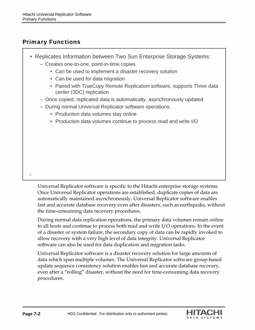
• Replicates Information between Two Sun Enterprise Storage Systems – Creates one-to-one, point-in-time copies
• Can be used to implement a disaster recovery solution • Can be used for data migration• Paired with TrueCopy Remote Replication software, supports Three data
center (3DC) replication– Once copied, replicated data is automatically, asynchronously updated– During normal Universal Replicator software operations:
• Production data volumes stay online• Production data volumes continue to process read and write I/O
Universal Replicator software is specific to the Hitachi enterprise storage systems. Once Universal Replicator operations are established, duplicate copies of data are automatically maintained asynchronously. Universal Replicator software enables fast and accurate database recovery even after disasters, such as earthquake, without the time-consuming data recovery procedures.
During normal data replication operations, the primary data volumes remain online to all hosts and continue to process both read and write I/O operations. In the event of a disaster or system failure, the secondary copy of data can be rapidly invoked to allow recovery with a very high level of data integrity. Universal Replicator software can also be used for data duplication and migration tasks.
Universal Replicator software is a disaster recovery solution for large amounts of data which span multiple volumes. The Universal Replicator software group-based update sequence consistency solution enables fast and accurate database recovery, even after a “rolling” disaster, without the need for time-consuming data recovery procedures.

Hitachi Universal Replicator Software Key Features
HDS Confidential: For distribution only to authorized parties. Page 7-3
Key Features
4
• Master (or Main) Control Unit (MCU) – Contains primary volumes (P-VOLs) and Master Journal Volumes
• Remote Control Unit (RCU) – Contains secondary volumes (S-VOLs) and Restore Journal Volumes
• P-VOL (Primary Volume) – Active, online LUN which is also called the Base Journal
• S-VOL (Secondary Volume) – Remote copy of the P-VOL • Journal Volume – Stores differential data if necessary• Journal Groups – Contains both data volumes and 1 to 16 journal
volumes; maintains volume consistency by operating on multiple data volumes with one command
Universal Replicator software enables you to create duplicate volumes by copying data from the primary data volumes in the primary system (MCU) to the secondary data volumes in the secondary system (RCU) at the remote location.

Hitachi Universal Replicator Software Key Features
Page 7-4 HDS Confidential: For distribution only to authorized parties.
5
• Remote Connections (Links)– Bi-directional fibre connection to send and receive data between MCU and
RCU– Minimum two initiator ports, one in each system– Minimum two RCU target ports, one in each system– Unlike TrueCopy software bundle, Universal Replicator software remote copy
connections (links) are not assigned to logical control units (LCUs)– Only Fibre Channel is supported
MCU RCUInitiator
Initiator
RCU Target
RCU Target
6
• Remote Connections (Links)– At least two fibre connections required
• Fibre connection 1 makes a request to remote site• Fibre connection 2 sends read journal command and journal copy
– Requires four reserved CHA ports, but since CHA ports are configured in couples, a total of eight CHA ports will be reserved
– Each site involved in data replication will include:• One initiator port• One RCU target port
– Fibre connection 1: Initiator RCU target– Fibre connection 2: RCU target Initiator
Note: Two or more initiator ports must be configured before you can add the secondary systems and create the Universal Replicator volume pairs.

Hitachi Universal Replicator Software Key Features
HDS Confidential: For distribution only to authorized parties. Page 7-5
7
• Journal Volumes– Offline physical logical devices (LDEVs) on Universal Storage Platform– Must be OPEN-V– Used on MCU (primary) and RCU (secondary) storage systems– Journal Group IDs can be different between MCU and RCU– Stores differential data anytime a volume write is performed– Comprised of metadata and journal data
• Metadata holds a pointer to differential data– Allows replication to continue after a communication failure– When data replication is initiated for the first time, volumes only store
metadata– Journal volumes can be dynamically concatenated to create larger journal
volumes
Note: These volumes can not be mapped to a port. If the volume is already mapped, the journal volume creation process will fail.
When Universal Replicator software is used, data to be copied will be temporarily stored in journal volumes, which are a type of physical logical devices. Universal Replicator software enables you to configure and manage highly reliable data replication systems by using journal volumes to reduce chances of suspension of copy operations; copy operations can be suspended due to restrictions on data transfers from the primary site to the secondary site. The journal volume in the MCU is referred to as the primary journal volume. The journal volume in the RCU is referred to as the secondary journal volume. The updates (sometimes referred to as update data) that will be stored in journal volumes are called journal data. Because journal data will be stored in journal volumes, you can perform and manage highly reliable remote copy operations without suspension of remote copy operations. For example: Even if a communication path between the primary system and the secondary system fails temporarily, remote copy operations can continue after the communication path is recovered. If data transfer from hosts to the primary system is temporarily faster than data transfer between the primary system and the secondary system, remote copy operations between the primary system and the secondary system can continue. Because journal volumes can contain much more update data than the cache memory can contain, remote copy operations can continue if data transfer from hosts to the primary system is faster for a relatively long period of time than data transfer between the primary system and the secondary system.

Hitachi Universal Replicator Software Key Features
Page 7-6 HDS Confidential: For distribution only to authorized parties.
8
• Journal Groups– Comprised of data volumes and journal volumes– Maximum of 4,096 data volumes and 64 journal volumes can comprise one
journal group– Maximum of 256 journal groups– Enables multiple data volumes to be managed simultaneously– Manages update sequence to maintain data consistency
Note: If journal groups have been created, additional journal volumes can be registered to the journal group only when the entire journal group is suspended.
A journal group consists of data volumes and journal volumes in the primary site, or it consists of data volumes and journal volumes in the secondary site. A journal group enables multiple data volumes and journal volumes to be grouped and it enables Universal Replicator software to be tailored to the unique business content of the user. A maximum of 16 LDEVs can be combined to create one journal group. The data volume in the primary journal group is also called the primary data volume. The journal volume in the primary journal group is called the primary journal volume. The data volume in the secondary journal group is similarly called the secondary data volume. The journal volume in the secondary journal group is called the secondary journal volume.
The data update sequence from the host is managed per the journal group. The data update sequence consistency between the primary and secondary journal groups to be paired is maintained and ensured. The primary and secondary journal groups are managed according to the journal group number. The journal numbers of primary and secondary journal groups that are paired can be different. One data volume and one journal volume can belong to only one journal group.

Hitachi Universal Replicator Software Key Features
HDS Confidential: For distribution only to authorized parties. Page 7-7
9
• Illustration of Journal Volumes and Data Volumes Within Journal Groups– All data volumes within a journal group share journal volumes.– Journal volumes are divided into one metadata area and 32 journal data
areas. These areas are called extents. In the case of multiple journal volume in the group, journal data is striped across extents.
The journal volume and data volumes within the journal group
Metadata 1
Journal volume#1
area Journal data area 32
1 1 1
3232
32
Journal volume#2
Journal volume#3 Journal volume#16
Metadata area Journal data area
Metadata area
Journal data area
Metadata area
Journal data area
DATAVOLUMES
10
• Asynchronous replication has little effect on host I/O response time• Long distance remote copy with DWDM (dark fiber), ATM or Internet• Disaster recovery capability in metropolitan and transcontinental network
cluster environment• Robustness for link failure
Universal Replicator(Asynchronous remote
copy)
Dark fiber /Public Line (ATM) /
Internet
Universal Storage Platform V and VM
MCU
Primary Site (Los Angeles)
RAID Manager RAID Manager
Fibre Channel
Fibre Channel
RAID Manager RAID Manager
Fibre Channel
Universal Storage Platform, Universal Storage Platform
VMRCU
Secondary Site (New York)
Fibre Channel
Storage Navigator program
Storage Navigator
LAN LAN
Extender Extender
Hitachi Universal Replicator Software Key Features
Page 7-8 HDS Confidential: For distribution only to authorized parties.
11
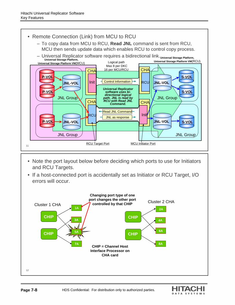
• Remote Connection (Link) from MCU to RCU– To copy data from MCU to RCU, Read JNL command is sent from RCU,
MCU then sends update data which enables RCU to control copy process.– Universal Replicator software requires a bidirectional link.
CHA
InitP-VOL
P-VOL
P-VOL
CHA
RCU
CHA
Init
CHA
RCUS-VOL
S-VOL
S-VOL
JNL-VOL JNL-VOL
JNL-VOL JNL-VOL
JNL Group
JNL Group
JNL Group
JNL Group
Read JNL Command
Control Information
Universal Storage Platform,Universal Storage Platform VM(MCU)
JNL as response
Logical pathMax 8 per DKC
16 per MCU/RCU
Universal Replicator software uses bi-directional logical
path. JNL is read by RCU with Read JNL
Command.
RCU Target Port MCU Initiator Port
Universal Storage Platform,Universal Storage Platform VM(RCU)
12
• Note the port layout below before deciding which ports to use for Initiators and RCU Targets.
• If a host-connected port is accidentally set as Initiator or RCU Target, I/O errors will occur.
Cluster 1 CHACluster 2 CHA
CHIP
CHIP
1A
CHIP
CHIP
8A
3A
5A
7A
6A
4A
2A
CHIP = Channel Host Interface Processor on
CHA card
Changing port type of one port changes the other port
controlled by that CHIP

Hitachi Universal Replicator Software Key Features
HDS Confidential: For distribution only to authorized parties. Page 7-9
13
• Host I/O process completes immediately after storing write data to the cache memory of primary storage system (MCU). Then the data is asynchronously copied to secondary storage system (RCU)
• MCU will store data to be transferred in the Journal Cache that will be destaged to the Journal Volume in the event of link failure
• Universal Replicator software provides consistency of copied data by maintaining write order in copy process. To achieve this, it attaches write order information to the data in copy process
(3) Asynchronous remote copy
Primary Storage (MCU)
P-VOL S-VOL
Secondary Storage (RCU)Host
(1) Write I/O
(4) Remote copy complete(2) Write complete JNL-VOL JNL-VOL

Hitachi Universal Replicator Software How Universal Replicator Software Works
Page 7-10 HDS Confidential: For distribution only to authorized parties.
How Universal Replicator Software Works
14
• Replication Process: – Initial Copy (Also Called Base Journal Copy)
• During Initial Copy process, pointers to data on the P-VOL are stored in the journal volumes. Write sequence number are assigned in the metadata area of the journal volume
• The base journal data is obtained from the P-VOL.• The data in the S-VOL synchronizes with the data in the P-VOL using the
sequence numbering scheme stored as metadata on the primary journal volume.
• This operation is conceptually similar to Initial Copy in TrueCopy Remote Replication bundle.
Journal obtain is the function to store the already stored data in the primary data volume as a base journal in the journal volume at the primary site. This function stores the write data as a journal data in the journal volume with every update of the primary data volume according to the write instruction from the host. The journal obtain operation is performed according to the instruction of PairCreate or PairResync operation from the primary site. The write sequence number from the host is assigned to the journal data. According to this information, the write sequence consistency at the secondary site can be maintained. The update data from the host is kept in the cache. Therefore, the journal obtain function for the update data is performed at another time from the recipient of update data from the host or the storage of data to the data volume.

Hitachi Universal Replicator Software How Universal Replicator Software Works
HDS Confidential: For distribution only to authorized parties. Page 7-11
15
• Replication Process – Initial Copy (Base Journal Copy)
Initial Copy (Base Journal)
Copy of P-VOL to Journal VOL in RCU. Restore Journal operation then moves data to S-VOL independently of host
I/O.
Journal Restore
Primary host Secondary host
Obtaining updated journal data
Write instruction
Primary data
volume
Master journal volume
Obtaining base-journalPrimary
subsystem
Secondary data
volume
Restore journal volume
Secondary subsystem
16
• Replication Process – Journal Obtain, Read, Copy, Restore– After Base Journal completes and primary data volume is updated by write
command from the host, the updated data has to be replicated on the S-VOL. This is the Update Copy.
• Update Copy starts as the Journal Obtain process is invoked when datais written as journal data to cache and then the journal volume. Control information is attached.
• MCU then sends Journal Obtain notification to RCU. This tells the RCU that pending data is now ready. It will remain in MCU cache until destaged to Journal Volume.
• RCU then pulls data from MCU with Read Journal command.• If available in cache, Journal Copy pulls from MCU cache and sends data
to RCU to be stored on secondary journal volume. If not in cache, data will come from MCU Journal Volume.
• Concurrently with Journal Copy, RCU executes Journal Restore to begin moving data from RCU Journal Volume to secondary data volume.

Hitachi Universal Replicator Software How Universal Replicator Software Works
Page 7-12 HDS Confidential: For distribution only to authorized parties.
17
• Guarantees the Write Order for Each JNL Group
Data (1)Data (2)Data (3)Data (4)Data (5)
MCU
Write data for P-VOLs of JNL Group 1
#1#2#3
#1#2
Write data for P-VOLs of JNL Group 0
Data (1)Data (2)Data (4)
JNL (1)JNL (2)
Metadata (including sequence#)
Write data
Data (3)Data (5)
JNL (3)
JNL (generated from write data)
P-VOL JNL-VOL
P-VOL JNL-VOL
JNL Group 0 JNL Group 1
Cache
RCU
#1#2#3
#1#2
JNL (1)JNL (2)
Metadata (including SCI)
JNL (5)JNL (3)
JNL (generated from write data)
JNL-VOL
JNL-VOL
JNL Group 2 JNL Group 3
Cache
S-VOL
S-VOL
(4)(1)(2)
Transfer order different from the write order.
(5)(3)
Transfer by Read JNL Command
issued from RCU
Paired
Paired
1
2
3
4
5
6
JNL (4)JNL (5)
JNL (4)
18
• Journal FunctionsUpdate Copy Process:
Differential data is stored in journal volume then the write sequence
number is assigned within metadata
During initial copy process, pointers to data volume are
stored in journal volumeWrite sequence number assigned
inside metadata
1,2
4Journal Copy function
Primary host Secondary host
Journal obtain
function
Master journal volume
Master journal volume
Restore journal volume
Primary site Secondary site
Primary subsystem
Secondary data
volume
Secondary subsystem
Issuing Read Journal command
3
Hitachi Universal Replicator Software How Universal Replicator Software Works
HDS Confidential: For distribution only to authorized parties. Page 7-13
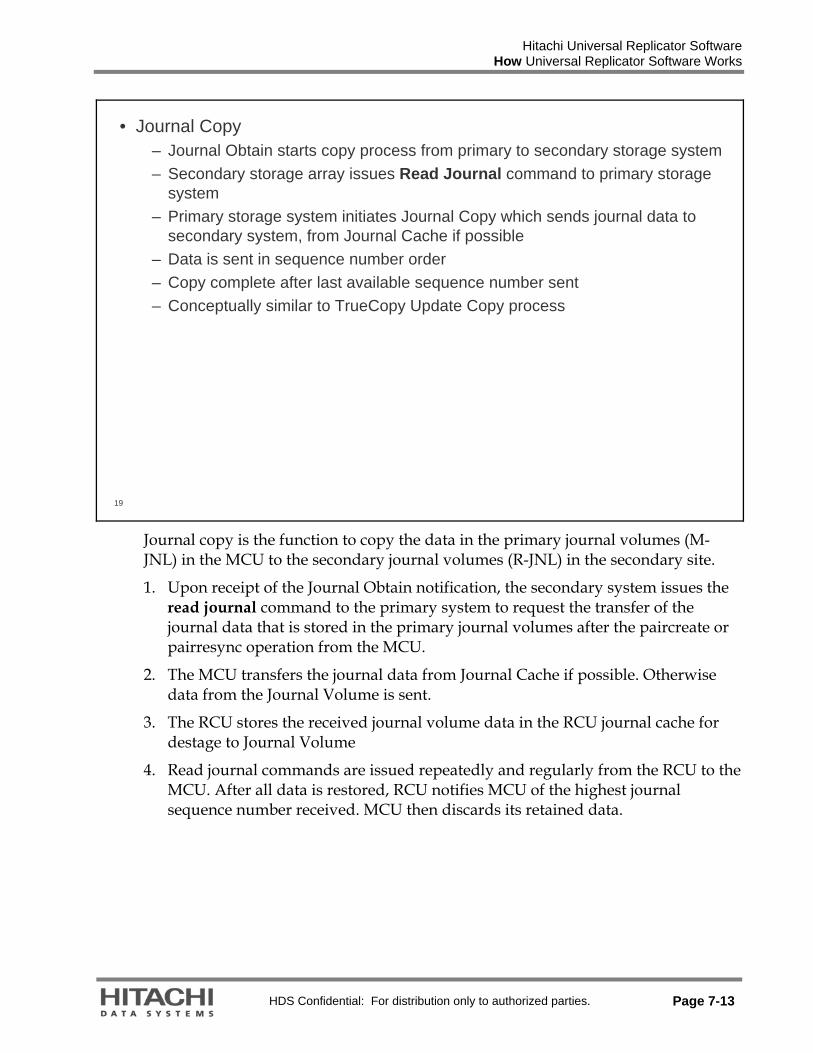
19
• Journal Copy– Journal Obtain starts copy process from primary to secondary storage system– Secondary storage array issues Read Journal command to primary storage
system– Primary storage system initiates Journal Copy which sends journal data to
secondary system, from Journal Cache if possible– Data is sent in sequence number order– Copy complete after last available sequence number sent– Conceptually similar to TrueCopy Update Copy process
Journal copy is the function to copy the data in the primary journal volumes (M-JNL) in the MCU to the secondary journal volumes (R-JNL) in the secondary site.
1. Upon receipt of the Journal Obtain notification, the secondary system issues the read journal command to the primary system to request the transfer of the journal data that is stored in the primary journal volumes after the paircreate or pairresync operation from the MCU.
2. The MCU transfers the journal data from Journal Cache if possible. Otherwise data from the Journal Volume is sent.
3. The RCU stores the received journal volume data in the RCU journal cache for destage to Journal Volume
4. Read journal commands are issued repeatedly and regularly from the RCU to the MCU. After all data is restored, RCU notifies MCU of the highest journal sequence number received. MCU then discards its retained data.

Hitachi Universal Replicator Software How Universal Replicator Software Works
Page 7-14 HDS Confidential: For distribution only to authorized parties.
20
• Journal Restore – Process to move the stored data in the restore journal volume to the
secondary data volume at the secondary site– The data in the restore journal volume is restored to the secondary data
volume according to the write sequence number– This will ensure the write sequence consistency between the primary and
secondary data volumes– After the journal data is restored to the secondary data volume, RCU journal
data is discarded

Hitachi Universal Replicator Software How Universal Replicator Software Works
HDS Confidential: For distribution only to authorized parties. Page 7-15
21
• Journal Restore–Writes to cache of S-VOL first–Simulates a journal commit
Primary host Secondary host
Discard journal
M-JNLP-VOL
MCU
S-VOLR-JNL
RCU
Read Journal command
Journal restore is the function to reflect the stored data in the secondary journal volume to the secondary data volume at the secondary site. The data in the secondary journal volume are restored to the secondary data volume according to the write sequence number. This will ensure the write sequence consistency between the primary and secondary data volumes. After the journal data are restored to the secondary data volume, the journal data are discarded at the secondary site.

Hitachi Universal Replicator Software Configurations
Page 7-16 HDS Confidential: For distribution only to authorized parties.
Configurations
22
• Two Data Center (with ShadowImage Replication software In the Remote CU)– This is the usual configuration. ShadowImage software provides a copy of the
replicated data that can be used by other applications such as backups, development, and others.
Primary data volume
Master journal volume
MCU
RCU
Universal Replicator software
ShadowImage
S-VOL
P-VOL
Secondary data volume
Restore journal volume

Hitachi Universal Replicator Software Universal Replicator Software Configurations
HDS Confidential: For distribution only to authorized parties. Page 7-17
Universal Replicator Software Configurations
• Two Data Center, Mirrored Sites
MCU/RCU MCU/RCU
P-VOL
S-VOL
S-VOL
P-VOL
Universal Replicator Software
Universal Replicator Software
24
• Three Data Center Multi-target– Provides two copies of the P-VOL data
P-VOL/Prm. data VOL
S-VOL
JNLVOL
TrueCopy Synchronous software secondary site
Universal Replicator software (long distance) (for
use as an alternative)
Universal Replicator secondary site
TrueCopy Synchronous software (short
distance)
Master JNLVOL
Restore JNLVOL
Sec. data VOL
Universal Replicator software (long distance)

Hitachi Universal Replicator Software Universal Replicator Software Configurations
Page 7-18 HDS Confidential: For distribution only to authorized parties.
25
• Three Data Center Cascade– Corresponds to other vendors 3DC cascade configuration– Provides two copies of the P-VOL data
P-VOL
Restore JNLVOL
Secondary data VOL
Master JNLVOL
S-VOL/Prim. data VOL
Master JNLVOL
Primary site
Intermediate site
Secondary site
TrueCopy Synchronous software (short distance)
Universal Replicator software (Remote distance)
Hitachi Universal Replicator Software Volume Specifications
HDS Confidential: For distribution only to authorized parties. Page 7-19
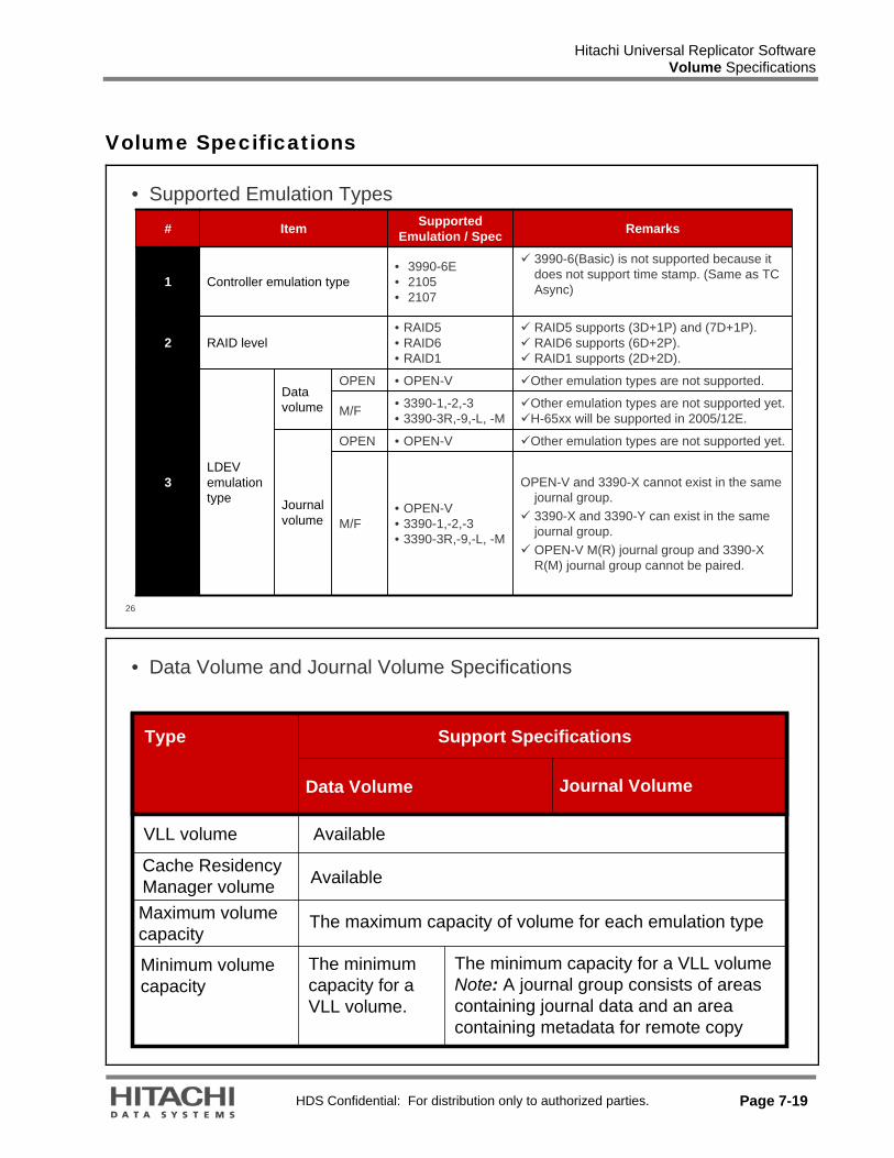
Volume Specifications
26
• Supported Emulation Types
Journal volume
RAID level2
Item
LDEV emulation type
Controller emulation type
Data volume
3990-6(Basic) is not supported because it does not support time stamp. (Same as TC Async)
Other emulation types are not supported. • OPEN-VOPEN
3
Other emulation types are not supported yet. • OPEN-VOPEN
Other emulation types are not supported yet.H-65xx will be supported in 2005/12E.
• 3390-1,-2,-3• 3390-3R,-9,-L, -MM/F
RAID5 supports (3D+1P) and (7D+1P). RAID6 supports (6D+2P). RAID1 supports (2D+2D).
• RAID5• RAID6• RAID1
M/F• OPEN-V• 3390-1,-2,-3• 3390-3R,-9,-L, -M
• 3990-6E• 2105• 2107
Supported Emulation / Spec
OPEN-V and 3390-X cannot exist in the same journal group. 3390-X and 3390-Y can exist in the same journal group. OPEN-V M(R) journal group and 3390-X R(M) journal group cannot be paired.
Remarks
1
#
• Data Volume and Journal Volume Specifications
Type
Available
Maximum volume capacity
Cache Residency Manager volume
VLL volume
Journal VolumeData Volume
Support Specifications
Minimum volume capacity
Available
The maximum capacity of volume for each emulation type
The minimum capacity for a VLL volume.
The minimum capacity for a VLL volume Note: A journal group consists of areas containing journal data and an area containing metadata for remote copy

Hitachi Universal Replicator Software Volume Specifications
Page 7-20 HDS Confidential: For distribution only to authorized parties.
28
• Journal Group Specifications for Universal Storage Platform V or VM– 64 journal volumes in a group
Hitachi Universal Replicator Software Pair Status Transition
HDS Confidential: For distribution only to authorized parties. Page 7-21
Pair Status Transition
29
• Volume Pair Status Transition
PP-- VOLVOL
SMPLSMPL
PSUEPSUE
COPYCOPY
PAIRPAIR
SS-- VOLVOL
PSUSPSUSPSUSPSUS
PSUEPSUE
SSUSSSUSPAIRPAIRCOPYCOPYSMPLSMPL
pairsplit
paircreate
pairresync
pairdelete
In case of remote link failure,S--VOL does not change to PSUE by itself.
Only indication from MCU can
change the S--VOL status
PP-- VOLVOL
SMPLSMPL
PSUEPSUE
COPYCOPY
PAIRPAIR
SS-- VOLVOL
PSUSPSUSPSUSPSUS
PSUEPSUE
SSUSSSUSPAIRPAIRCOPYCOPYSMPLSMPL
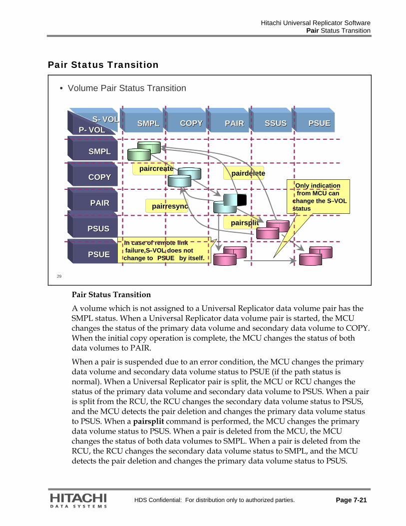
Pair Status Transition
A volume which is not assigned to a Universal Replicator data volume pair has the SMPL status. When a Universal Replicator data volume pair is started, the MCU changes the status of the primary data volume and secondary data volume to COPY. When the initial copy operation is complete, the MCU changes the status of both data volumes to PAIR.
When a pair is suspended due to an error condition, the MCU changes the primary data volume and secondary data volume status to PSUE (if the path status is normal). When a Universal Replicator pair is split, the MCU or RCU changes the status of the primary data volume and secondary data volume to PSUS. When a pair is split from the RCU, the RCU changes the secondary data volume status to PSUS, and the MCU detects the pair deletion and changes the primary data volume status to PSUS. When a pairsplit command is performed, the MCU changes the primary data volume status to PSUS. When a pair is deleted from the MCU, the MCU changes the status of both data volumes to SMPL. When a pair is deleted from the RCU, the RCU changes the secondary data volume status to SMPL, and the MCU detects the pair deletion and changes the primary data volume status to PSUS.
Hitachi Universal Replicator Software Pair Volume Status: Volume Status Conditions
Page 7-22 HDS Confidential: For distribution only to authorized parties.
Pair Volume Status: Volume Status Conditions
30
Read Only; Read and Write if write option is enabled
Read / Write
This data volume pair is not synchronized, because the user has split the pair (pairsplit-r), or because the user has deleted the pair from the RCU (pairsplit-S). For Universal Replicator pairs, the MCU and RCU keep track of any journal data that were discarded during the pairsplit-r operation. While a pair is split, the MCU and RCU keep track of the primary data volume and secondary data volume tracks which are updated.
PSUS
Read OnlyRead / Write
This data volume pair is synchronized. Updates to the primary data volume are duplicated on the secondary data volume.
PAIR
Read OnlyRead / Write
The initial copy operation for this pair is in progress. This data volume pair is not yet synchronized. When the initial copy is completed, the status changes to PAIR.
COPY
Read / Write
Read / Write
This volume is not currently assigned to a Universal Replicator software data volume pair. This volume does not belong to the journal group. When this volume is added to a Universal Replicator data volume pair, its status will change to COPY.
SMPL
S-VOL Volume Access
P-VOL Volume Access
DescriptionPair Status
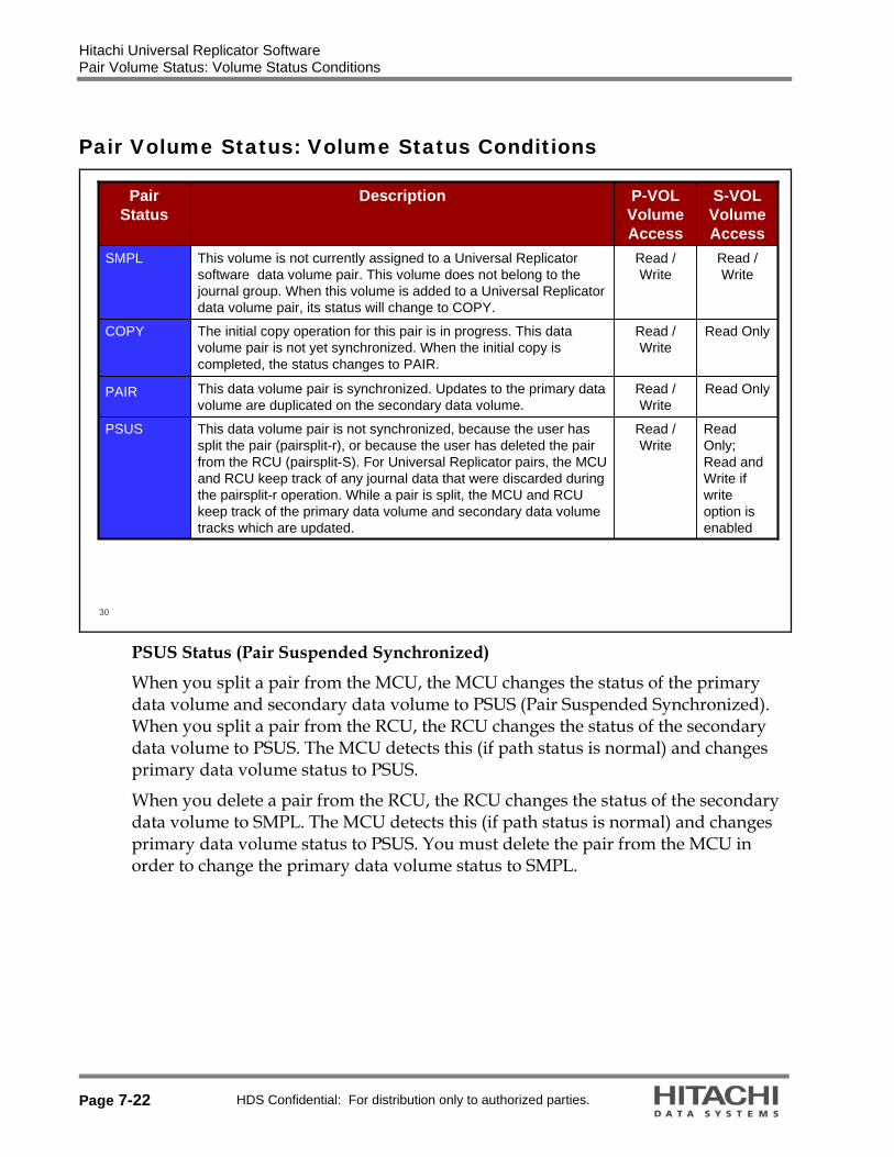
PSUS Status (Pair Suspended Synchronized)
When you split a pair from the MCU, the MCU changes the status of the primary data volume and secondary data volume to PSUS (Pair Suspended Synchronized). When you split a pair from the RCU, the RCU changes the status of the secondary data volume to PSUS. The MCU detects this (if path status is normal) and changes primary data volume status to PSUS.
When you delete a pair from the RCU, the RCU changes the status of the secondary data volume to SMPL. The MCU detects this (if path status is normal) and changes primary data volume status to PSUS. You must delete the pair from the MCU in order to change the primary data volume status to SMPL.

Hitachi Universal Replicator Software Pair Volume Status: Volume Status Conditions
HDS Confidential: For distribution only to authorized parties. Page 7-23
31
Read Only
Read/WriteUniversal Replicator monitors the total amount of data in the journal volume. If the amount of data exceeds the threshold (95% - 99%), the pair status changes from COPY or PAIR to PFUL. The write data that inflows is monitored during the specified time (Data Overflow Watch). The time period of monitoring can be set using the Storage Navigator PC (default setting is 90 seconds).
PFUL
Read Only
Read/Write; Read Only If Fenced
This data volume pair is not synchronized, because the MCU or RCU has suspended the pair due to an error condition. For Universal Replicator pairs the MCU and RCU keep track of any journal data that were discarded during the suspension operation. The MCU keeps track of the primary data volume tracks which are updated while the pair is suspended.
PSUE
S-VOL Volume Access
P-VOL Volume Access
DescriptionPair Status
PSUE Status (Pair Suspended Error)
If the MCU detects a Universal Replicator software suspension condition (error), the MCU changes the primary data volume (and secondary data volume if necessary) status to PSUE.
If the RCU detects a Universal Replicator software suspension condition, the RCU changes the secondary data volume status to PSUE. The MCU detects this (if path status is normal) and changes primary data volume status to PSUS.

Hitachi Universal Replicator Software Pair Volume Status Conditions
Page 7-24 HDS Confidential: For distribution only to authorized parties.
Pair Volume Status Conditions
32
S-VOL Volume Access
P-VOL Volume Access
DescriptionPair Status
Read Only; Read and Write if write option is enabled
Read/WriteIf the time period exceeds the specified monitoring time period,the pair status changes from PFUL to PFUS, and the pair is suspended.
PFUS
Read/WriteRead/WriteThe data can be written into the secondary data volume that is reassigned from the primary data volume during processing of resynchronization (Takeover).
SSWS
PFUS (Pair Full Suspended)
SSWS (Secondary Swap Suspended)
Takeover function is active.

Hitachi Universal Replicator Software Volume Status Conditions
HDS Confidential: For distribution only to authorized parties. Page 7-25
Volume Status Conditions
33
S-VOL Volume Access
P-VOL Volume Access
DescriptionPair Status
Read OnlyRead/WriteThis pair is not synchronized. This pair is in transition from PAIR, COPY, or PSUS/PSUE to SMPL. When the pairsplit-S operation is requested, the status of all affected pairs changes to Deleting. When the pairsplit-S operation is complete, the status changes to SMPL.
Deleting
Read OnlyRead/WriteThis pair is not synchronized. This pair is in transition from PAIR or COPY to PSUS/PSUE. When the split/suspend pair operation is requested, the status of all affected pairs changes to Suspending. When the split/suspend operation is complete, the status changes to PSUS/PSUE.
Suspending
Hitachi Universal Replicator Software Pair Volume Status
Page 7-26 HDS Confidential: For distribution only to authorized parties.
Pair Volume Status
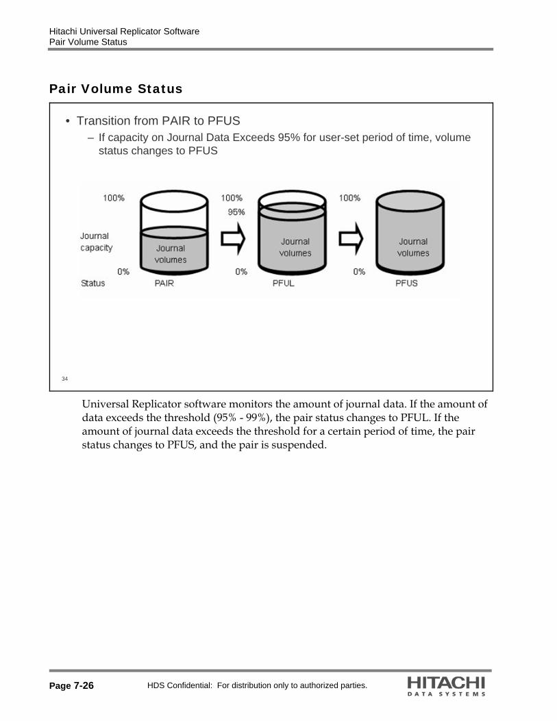
34
• Transition from PAIR to PFUS– If capacity on Journal Data Exceeds 95% for user-set period of time, volume
status changes to PFUS
Universal Replicator software monitors the amount of journal data. If the amount of data exceeds the threshold (95% - 99%), the pair status changes to PFUL. If the amount of journal data exceeds the threshold for a certain period of time, the pair status changes to PFUS, and the pair is suspended.

Hitachi Universal Replicator Software Preparation for Operations
HDS Confidential: For distribution only to authorized parties. Page 7-27
Preparation for Operations
35
• Preparation for Universal Replicator software Operations– Universal Replicator software license keys installed on two Universal Storage
Platform V or VM– At least two logical fibre paths should be configured and activated between
the Universal Storage Platform V or VM– Two Initiator and two RCU Target ports must be configured on each Universal
Storage Platform V or VM– At least one journal group must be present– A list of candidate P-VOLs and associated S-VOLs showing:
• Port ID• Host Group ID• Logical unit number (LUN)

Hitachi Universal Replicator Software Preparation for Operations
Page 7-28 HDS Confidential: For distribution only to authorized parties.
36
• Accessing Universal Replicator software Interface– Open Storage Navigator program on primary storage system (main control
unit - MCU).– Click Universal
Replicator.– Click on Pair
Operation.
To begin data replication, open Storage Navigator program in Modify mode and navigate to the Universal Replicator software interface. When the Universal Replicator software interface has opened, click on the Pair Operation. When the tab opens, all mapped LUNS will be listed on the left hand side of the window. Select from the list of volumes, which are the Universal Replicator production volumes.
Note: Universal Replicator software only supports Open-V type volumes.

Hitachi Universal Replicator Software Overview of Commands
HDS Confidential: For distribution only to authorized parties. Page 7-29
Overview of Commands
37
Resynchronizes a pair. When PSUE, an initial copy is performedStatus transition: PSUS/PSUE PAIR
Pairresync
Splits a pairStatus transition: Any status/SMPL and PSUE PSUS
Pairsplit –r
Deletes a Universal Replicator software volume pairStatus transition: Any status/SMPL SMPL
Pairsplit –S
Creates a Universal Replicator software volume pairStatus transition: SMPL COPY PAIR
Paircreate
Displays detailed information about a pair of data volumes Status transition: N/A
Pairdisplay
Function/DescriptionCommand
Hitachi Universal Replicator Software Commands — Paircreate Overview
Page 7-30 HDS Confidential: For distribution only to authorized parties.
Commands — Paircreate Overview
38
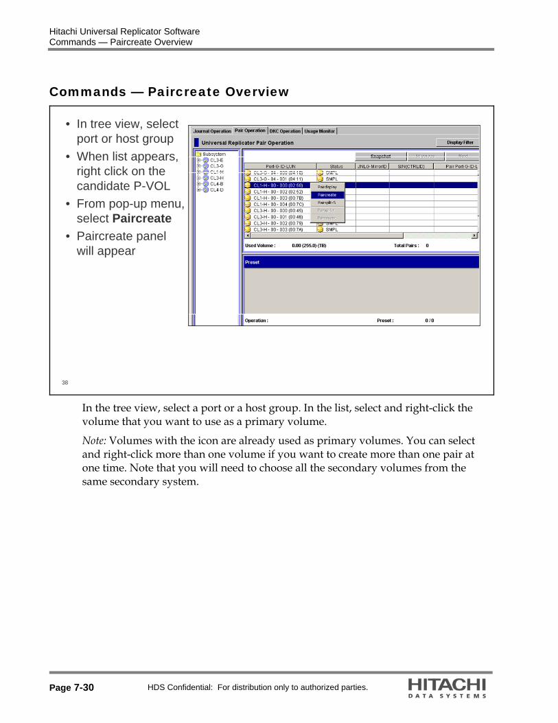
• In tree view, select port or host group
• When list appears, right click on the candidate P-VOL
• From pop-up menu, select Paircreate
• Paircreate panel will appear
In the tree view, select a port or a host group. In the list, select and right-click the volume that you want to use as a primary volume.
Note: Volumes with the icon are already used as primary volumes. You can select and right-click more than one volume if you want to create more than one pair at one time. Note that you will need to choose all the secondary volumes from the same secondary system.

Hitachi Universal Replicator Software Paircreate — S-VOL Input
HDS Confidential: For distribution only to authorized parties. Page 7-31
Paircreate — S-VOL Input
39
• Select S-VOL by entering:– Port ID– Host Group ID– LUN number
• If S-VOL information is not known, open Storage Navigator feature on a remote system and look at LUN Manger
When the dialog box appears, select the appropriate S-VOL, Mirror, and CT Group. S-VOL Values:
Port – S-VOL Port (Specify the port number with two characters, for instance, you can abbreviate CL1-A to 1A (not case-sensitive)).
GID – Host Group number LUN – LUN number
If you need a reference, please look at the LUN map listing in the Pair Operation tab to find the S-VOL you want. If a logical volume is an external volume, the symbol "#" appears after the LDEV number. For detailed information about external volumes, please refer to the Universal Volume Manager User's Guide. If you selected more than one primary data volume, select the secondary data volume for the primary data volume being displayed. The secondary data volumes for the rest of the primary data volumes are automatically assigned according to the LUN. For example, if you select three primary data volumes and select LUN01 as the S-VOL for the first primary data volume, the secondary data volumes for the two other primary data volumes will be LUN02 and LUN03.

Hitachi Universal Replicator Software Paircreate — Configure Journal Groups
Page 7-32 HDS Confidential: For distribution only to authorized parties.
Paircreate — Configure Journal Groups
40
• M-JNL: JNL Group in Master DKC • R-JNL: JNL Group in Remote
DKC• Mirror ID: used in three data
center (3DC)• Select CT Group• Select appropriate remote disk
controller
Mirror:
M-JNL: “MASTER” Journal Group. Mirror ID: Leave as default. Used only in 3DC configurations R-JNL: “RESTORE” Journal Group CT Group: Assign a Consistency Group number. Ensure that the CT Group selected is not in use by ShadowImage software or TrueCopy Remote Replication software.
If a Universal Replicator software volume pair already exists in the Journal Group, there will be “*” next to the C/T group number. Also, the corresponding pairs of journal volumes will appear automatically.
Hitachi Universal Replicator Software Paircreate — Details
HDS Confidential: For distribution only to authorized parties. Page 7-33
Paircreate — Details
41
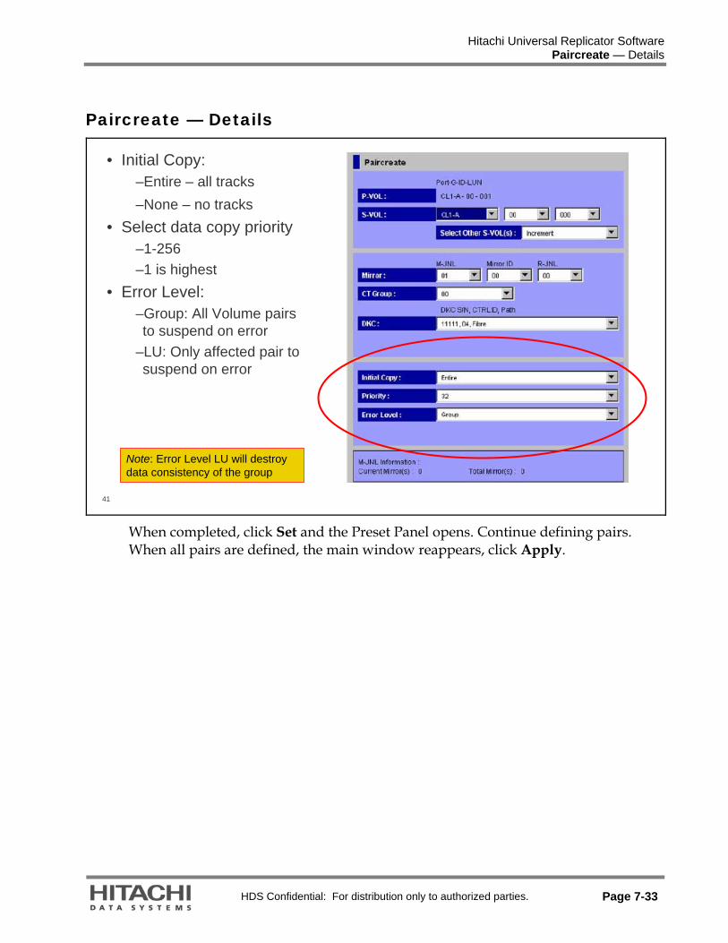
• Initial Copy:–Entire – all tracks–None – no tracks
• Select data copy priority–1-256–1 is highest
• Error Level:–Group: All Volume pairs to suspend on error
–LU: Only affected pair to suspend on error
Note: Error Level LU will destroy data consistency of the group
When completed, click Set and the Preset Panel opens. Continue defining pairs. When all pairs are defined, the main window reappears, click Apply.

Hitachi Universal Replicator Software Commands — PairCreate Set/Apply
Page 7-34 HDS Confidential: For distribution only to authorized parties.
Commands — PairCreate Set/Apply
42
• Volume status will change from SMPL to Copy• When copy complete, volume will change to Pair

Hitachi Universal Replicator Software Commands
HDS Confidential: For distribution only to authorized parties. Page 7-35
Commands
43
• Pairdisplay Command– Displays detailed pair
Information• Alternative path• Progress• Which volumes are paired• Journal group
– Can also be displayed through Storage Navigator feature on a secondary system
• pairdisplay is reversed
Both the primary system administrator and the secondary system administrator can perform this operation.
Pairdisplay Panel: Status: Indicates the status of the pair. Alternative Path: Indicates the alternate path. Progress: Indicates the progress of the initial copy operation. P-VOL: Indicates the primary volume.
The first line displays the port number, the host group ID, and the LUN of the primary volume.
The second line displays the device emulation type. The third line displays the volume capacity.
S-VOL: Indicates the secondary volume. The first line displays the port number, the host group ID, and the LUN of the secondary volume.
The second line displays the device emulation type. The third line displays the volume capacity.

Hitachi Universal Replicator Software Commands
Page 7-36 HDS Confidential: For distribution only to authorized parties.
M-JNL Group: Indicates the master journal group. R-JNL Group: Indicates the restore journal group. Mirror ID: Indicates the mirror ID. CT Group: Indicates the consistency group number. DKC S/N (CTRL ID): Indicates the serial number and the controller ID of the secondary system. The controller ID is enclosed by parentheses.
Path Type: Indicates the channel type of the path interface between the systems (fibre).
Initial Copy Priority: Indicates priority (scheduling order) of the initial copy operations. The value can be within the range of 1 to 256 (disabled when the status becomes PAIR).
Error Level: Indicates the range used for splitting a pair when a failure occurs. The default is Group.
Group: If a failure occurs with a pair, all pairs in the consistency group where the pair belongs will be split.
LU: If a failure occurs with a pair, only the pair will be split. S-VOL Write: Indicates whether write I/O to the secondary volume is enabled or disabled (enabled only when the pair is split).
Other Information Established Time: Indicates the date and time when the volume pair was created. Updated Time: Indicates the date and time when the volume pair status was last updated.
Refresh the Pair Operation tab after this window is closed: If this check box is selected, the Pair Operation panel will be updated when the Pairdisplay panel closes.
Previous: Displays the pair status information for the previous pair in the list (the pair in the row above).
Next: Displays the pair status information for the next pair in the list (the pair in the row below). Note: The list displays a maximum of 1,024 rows at once. The Previous and Next buttons on the Pairdisplay panel can only be used for the currently displayed 1,024 rows.
Refresh: Updates the pair status information. Close: Closes the Pairdisplay panel.

Hitachi Universal Replicator Software Commands
HDS Confidential: For distribution only to authorized parties. Page 7-37
44
• Pairsplit –r (normal split)– In the list, select and
right-click the pair that you want to split
– The pair status must be COPY or PAIR
– From the pop-up menu, select Pairsplit-r
– The Pairsplit-r panel appears
Hitachi Universal Replicator Software Pairsplit –r
Page 7-38 HDS Confidential: For distribution only to authorized parties.
Pairsplit –r
45
• Select Options – S-VOL Write:
• Disabled by default• Enabled: allows R/W of
S-VOL after split– Range: Suspend pair
at group or volume level
– Suspend Mode: • Flush – Send update to
S-VOL• Purge – Discard update
data– Click Set– When main window appears,
click Apply
S-VOL Write: Allows you to specify whether to permit hosts to write data to the secondary volume. The default is Disable (in other words, do not permit):
Disable: Hosts cannot write data to the secondary volume while the pair is split. Enable: Hosts can write data to the secondary volume while the pair is split. This option is available only when the selected volume is a primary volume.
Range: Allows you to specify the split range. The default is LU if two or more pairs in the same consistency group are selected. The default is Group if not.
LU: Only the specified pair(s) will be split. Note: If you select pairs with PAIR status and other than PAIR status in the same consistency group, an unexpected suspension may occur during the pair operations (Pairsplit-r, Pairsplit-S, and Pairresync) under heavy I/O load conditions. You can estimate whether the I/O load is heavy or not from the rate of journal cache (around 30%), or if you cannot see the journal cache rate, from the frequency of host I/O. The suspend pair operations should be performed under light I/O load conditions.
Group: All pairs in the same consistency group(s) as the selected pair(s) will be split.
Note: If the following two conditions are satisfied and you select Apply, a warning message will be displayed and processing cannot be continued:

Hitachi Universal Replicator Software Pairsplit –r
HDS Confidential: For distribution only to authorized parties. Page 7-39
The Preset list contains two or more pairs belonging to the same consistency group.
The Range column displays Group for at least one of the above pairs.
To be able to continue processing, do either of the following: Ensure that the Range column displays LU for all pairs in the same consistency group.
In the Preset list, select all but one pair in the same consistency group, right-click the selected pairs, and then select Delete.
Suspend Mode: Allows you to specify how to deal with update data that has not been copied to the secondary volume. The default is Flush:
Flush: When you split the pair, update data will be copied to the secondary volume.
Purge: When you split the pair, update data will not be copied to the secondary volume. If you restore the pair later, the update data will be copied to the secondary volume.
Set: Applies the settings to the Preset list in the Pair Operation panel. Cancel: Discards the settings.

Hitachi Universal Replicator Software Pairsplit –r
Page 7-40 HDS Confidential: For distribution only to authorized parties.
46
• Apply– When main screen
appears, click Apply.
– Pair Operations screen will show suspending status.
– When complete, screen will show PSUS.

Hitachi Universal Replicator Software Pairresync
HDS Confidential: For distribution only to authorized parties. Page 7-41
Pairresync
47
• In the list, select and right-click the pair that you want to restore.
• The pair status must be PSUS or PSUE.
• From the pop-up menu, select Pairresync.
• The Pairresync panel appears.
Note: If the primary or secondary system is powered off and its backup batteries are fully discharged while pairs are suspended, the M-VOL/R-VOL bitmaps will not be retained. In this unlikely case, the primary/secondary system will mark all cylinders/tracks of all suspended volumes as modified, so that the primary system will perform the equivalent of an entire initial copy operation when the pairs are resumed.
If any pair was suspended due to an error condition (use the Pairdisplay panel to view the suspend type), make sure that the error condition has been removed. The primary system will not resume the pair(s) until the error condition has been removed.

Hitachi Universal Replicator Software Pairresync Options
Page 7-42 HDS Confidential: For distribution only to authorized parties.
Pairresync Options
48
• Select options to resynchronize volumes.
– Range: Resync pair at group or volume level
– Priority: I/O priority– Suspend condition
• JNL FULL• M-JNL FAILURE• R-JNL FAILURE
– Error level: Report error at group or volume
• Select Set.
The Pairresync Panel
Range: Allows you to specify the restore range. The default is LU if two or more pairs in the same consistency group are selected. The default is Group if not.
LU: Only the specified pair(s) will be restored. Group: All pairs in the same consistency group(s) as the selected pair(s) will be restored. Note: If the following two conditions are satisfied and you select Apply, a warning message will be displayed and processing cannot be continued:
The Preset list contains two or more pairs belonging to the same consistency group.
The Range column displays Group for at least one of the above pairs.
To be able to continue processing, do either of the following: Ensure that the Range column displays LU for all pairs in the same consistency group.
In the Preset list, select all but one pair in the same consistency group, right click the selected pairs, and then select Delete.

Hitachi Universal Replicator Software Pairresync Options
HDS Confidential: For distribution only to authorized parties. Page 7-43
Priority: Allows you to specify the desired priority (1-256) (scheduling order) for the pair-restoring operation.
DKC: Indicates the system. JNL Control: Allows you to specify whether to activate journals when the volume pair is restored. The default is Activate JNL if not active. Note: In the current version, the JNL Control option cannot be changed.
Activate JNL if not active: Activates journals per mirror when the volume pair is restored.
Stay in Current Status: Does not activate journals per mirror when the volume pair is restored.
Suspend Condition: Allows you to specify the condition for splitting the volume pair.
JNL full: Indicates whether to split the pair per master journal when the journal volume becomes full. The default is Yes.
M-JNL failure: Indicates whether to split the pair per master journal when a failure occurs in the master journal. The default is Yes.
R-JNL failure: Indicates whether to split the pair per mirror when a failure occurs in the restore journal. The default is Yes.
Error Level: Allows you to specify the range used for splitting a pair when a failure occurs.
Group: If a failure occurs with a pair, all pairs in the consistency group where the pair belongs will be split.
LU: If a failure occurs with a pair, only the pair will be split. Set: Applies the settings to the Preset list in the Pair Operation panel. Cancel: Discards the settings.

Hitachi Universal Replicator Software Pairresync
Page 7-44 HDS Confidential: For distribution only to authorized parties.
Pairresync
49
• Apply– When main
screen appears, click Apply.
– Pair Operations screen will show COPY status.

Hitachi Universal Replicator Software Deleting a Pair
HDS Confidential: For distribution only to authorized parties. Page 7-45
Deleting a Pair
50
• Pairsplit –S– In the list, select
and right-click the pair that you want to delete.
– From the pop-up menu, select Pairsplit-S.
– The Pairsplit-S panel appears.
The Pairsplit-S panel allows you to delete a pair of data volumes. To delete one or more pairs, follow the procedure below. Not only the primary system administrator but also the secondary system administrator can perform this operation.
Ensure that the Storage Navigator main panel is in Modify mode. For detailed information about how to do this, refer to Hitachi Storage Navigator Program User's Guide.
Ensure that the Pair Operation panel is displayed. In the tree view, select system or a port. In the list, select and right-click the pair that you want to delete. From the pop-up menu, select Pairsplit-S. The Pairsplit-S panel appears.

Hitachi Universal Replicator Software Deleting a Pair:
Page 7-46 HDS Confidential: For distribution only to authorized parties.
Deleting a Pair:
51
• Options– Range: Volume or Group
• If a consistency group exists, the default is group.
– Delete Mode:• Normal – Will succeed
only if MCU and RCU can communicate.
• Force – Will forcibly change P-VOL even with communication failure.
– Click Set.
The Pairsplit-S panel displays the following:
Range: Allows you to specify the delete range. The default is LU if two or more pairs in the same consistency group are selected. The default is Group if not.
LU: Only the specified pair(s) will be deleted.
Note: If you select pairs with PAIR status and other than PAIR status in the same consistency group, an unexpected suspension may occur during the pair operations (Pairsplit-r, Pairsplit-S, and Pairresync) under heavy I/O load conditions. You can estimate whether the I/O load is heavy or not from the rate of journal cache (around 30%), or if you cannot see the journal cache rate, from the frequency of host I/O. The pair operations should be performed under light I/O load conditions.
Group: All pairs in the same consistency group(s) as the selected pair(s) will be deleted. Caution: Do not use this option when deleting pairs at the secondary system during disaster recovery. Note: If the following two conditions are satisfied and you select Apply, a warning message will be displayed and processing cannot be continued:
The Preset list contains two or more pairs belonging to the same consistency group.

Hitachi Universal Replicator Software Deleting a Pair:
HDS Confidential: For distribution only to authorized parties. Page 7-47
The Range column displays Group for at least one of the above pairs.
To be able to continue processing, do either of the following:
Ensure that the Range column displays LU for all pairs in the same consistency group.
In the Preset list, select all but one pair in the same consistency group, right-click the selected pairs, and then select Delete.
Delete Mode: Allows you to specify whether to delete the pair(s) forcibly. When the status of the pair(s) to be deleted is SMPL or Deleting, the default setting is Force. Otherwise, the default setting is Normal.
Force: The pair(s) will forcibly be deleted even if the primary system is unable to communicate with the secondary system. This option may be used to free a host waiting for device-end from a primary system that cannot communicate with its the secondary system, thus allowing host operations to continue.
Normal: The pair(s) will be deleted only if the primary system is able to change the pair status of the primary and secondary volumes to SMPL.
Set: Applies the settings to the Preset list in the Pair Operation panel. Cancel: Discards the settings.
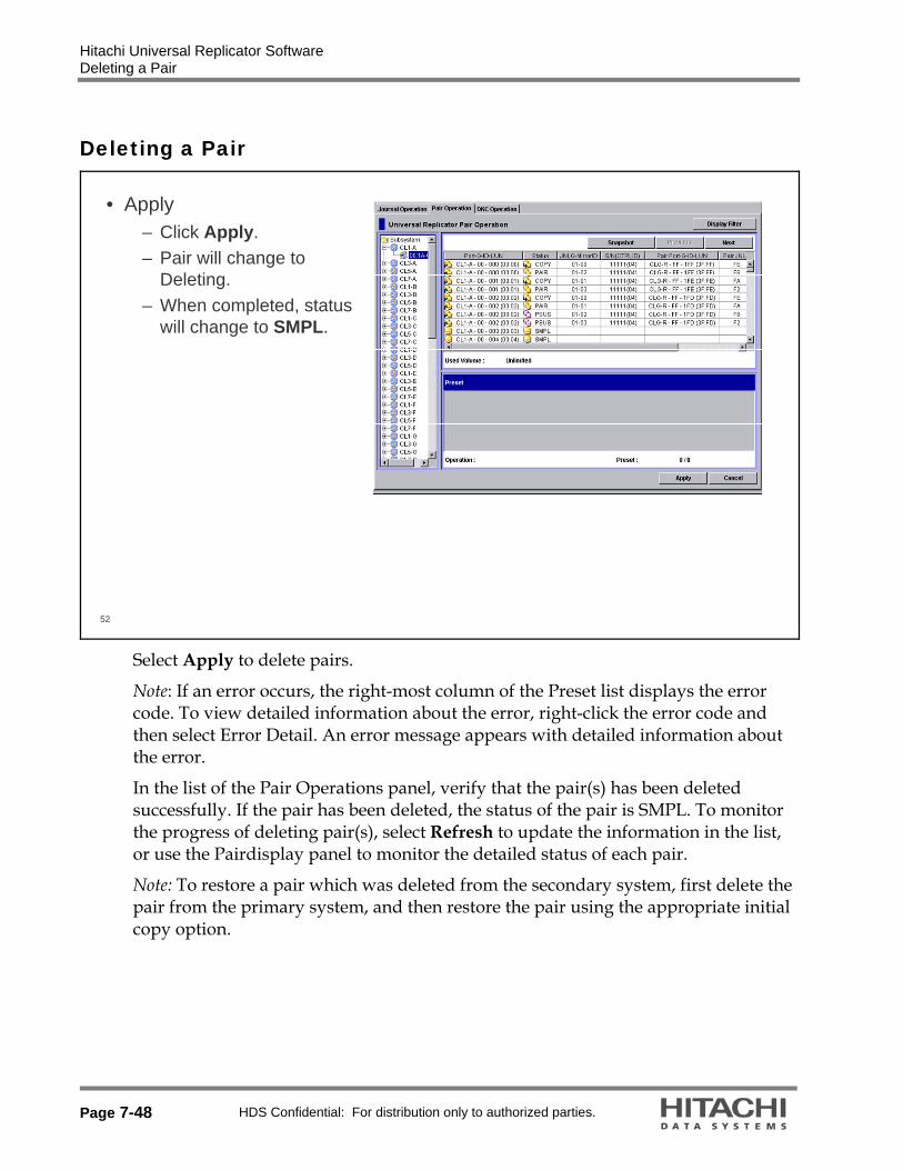
Hitachi Universal Replicator Software Deleting a Pair
Page 7-48 HDS Confidential: For distribution only to authorized parties.
Deleting a Pair
52
• Apply– Click Apply.– Pair will change to
Deleting.– When completed, status
will change to SMPL.
Select Apply to delete pairs.
Note: If an error occurs, the right-most column of the Preset list displays the error code. To view detailed information about the error, right-click the error code and then select Error Detail. An error message appears with detailed information about the error.
In the list of the Pair Operations panel, verify that the pair(s) has been deleted successfully. If the pair has been deleted, the status of the pair is SMPL. To monitor the progress of deleting pair(s), select Refresh to update the information in the list, or use the Pairdisplay panel to monitor the detailed status of each pair.
Note: To restore a pair which was deleted from the secondary system, first delete the pair from the primary system, and then restore the pair using the appropriate initial copy option.

Hitachi Universal Replicator Software Monitoring Pair Operations
HDS Confidential: For distribution only to authorized parties. Page 7-49
Monitoring Pair Operations
53
• Monitoring operations are performed by Usage Monitor– Collects I/O Stats for all LDEVs on Universal Storage Platform
• Functions– Start and stop monitoring– Display Usage Graph– Export Usage Data Monitor File
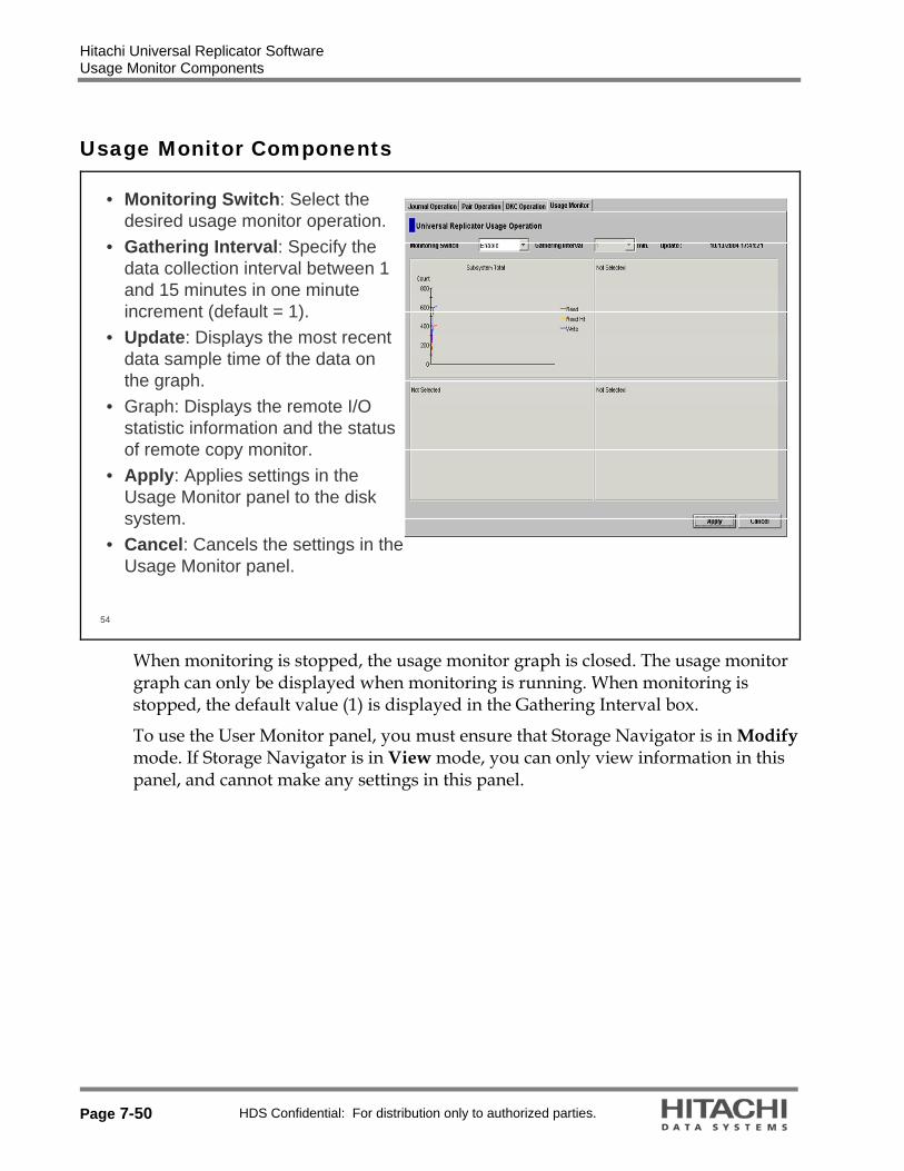
Hitachi Universal Replicator Software Usage Monitor Components
Page 7-50 HDS Confidential: For distribution only to authorized parties.
Usage Monitor Components
54
• Monitoring Switch: Select the desired usage monitor operation.
• Gathering Interval: Specify the data collection interval between 1 and 15 minutes in one minute increment (default = 1).
• Update: Displays the most recent data sample time of the data on the graph.
• Graph: Displays the remote I/O statistic information and the status of remote copy monitor.
• Apply: Applies settings in the Usage Monitor panel to the disk system.
• Cancel: Cancels the settings in the Usage Monitor panel.
When monitoring is stopped, the usage monitor graph is closed. The usage monitor graph can only be displayed when monitoring is running. When monitoring is stopped, the default value (1) is displayed in the Gathering Interval box.
To use the User Monitor panel, you must ensure that Storage Navigator is in Modify mode. If Storage Navigator is in View mode, you can only view information in this panel, and cannot make any settings in this panel.

Hitachi Universal Replicator Software Usage Monitor
HDS Confidential: For distribution only to authorized parties. Page 7-51
Usage Monitor
55
• Starting Usage Monitoring– Select the Usage Monitor tab– For Monitoring Switch, select Enable.– For Gathering Interval, set the desired sampling time interval (in minutes).
You can select it or type it in the field. The acceptable range is 1 to 15 minutes. The default is one minute.
– To start monitoring, click Apply.
If you set one minute for Gathering Interval, the sampling data will be held one day. If you set 15 minutes for Gathering Interval, the sampling data will be held 15 days. When the Gathering Interval is changed, the data obtained before changing is deleted.

Hitachi Universal Replicator Software Usage Monitor
Page 7-52 HDS Confidential: For distribution only to authorized parties.
56
• Stopping Usage Monitoring– To stop remote copy usage monitoring on the connected StorageTek 9990:
• Select the Usage Monitor tab.• For Monitoring Switch, select Disable.• To stop monitoring, select Apply.
– Depending on the load status of SVP, you may not be able to stop monitoring. If you cannot stop monitoring immediately, wait then select the Refreshbutton (top right of Storage Navigator feature panel) to check the status of the monitor.
– The collection of monitoring data continues, even if the panel is closed, until you stop monitoring operations. Monitoring data collection continues even if the SVP is rebooted.
Hitachi Universal Replicator Software Usage Monitor
HDS Confidential: For distribution only to authorized parties. Page 7-53
57
• Displaying the Usage Monitor Graph– When usage monitoring is running, the Usage Monitor panel can display user-
selected remote copy I/O statistics in real time. The I/O statistics data is collected according to the data-sampling rate selected in the Gathering Interval box.
The usage monitor graph plots the user-selected I/O statistics (up to 65 data points) on an x-y graph. The x-axis displays time while the y�axis displays the number of I/Os during the last sampling period. The legend (right side of the graph) indicates the data being displayed.
A value on the y-axis varies according to the maximum value of the statistical data that is displaying. If the value on the y�axis exceeds 10,000,000, the value is displayed in exponential notation (for example, 1E7 = 1�107 = 10,000,000; 2E8 = 2�108 = 200,000,000).

Hitachi Universal Replicator Software Usage Monitor
Page 7-54 HDS Confidential: For distribution only to authorized parties.
58
• Steps to Display the Usage Monitor Graph– Make sure that usage monitoring is running. – Right-click the graph area of the Usage Operations panel, and select Display
Item. The Display Item panel appears.– For Select LU, select an appropriate value.– In the Monitor Data area, select the I/O statistics data that you want to display
on the graph. You must select at least one.– Click Set to close the Display Item panel. The Usage Operations panel now
displays a graph showing the selected I/O statistics data for the selected LUs.– To enlarge the displayed graph, right-click the graph, and select Large Size.
To return the graph to normal size, right-click the graph, and select Normal Size.
Subsystem: Display I/O statistics for all LDEVs in the system.
JNL Group: Display I/O statistics for a specific journal group, select, and then enter a journal group number (00-FF).
Device: Display I/O statistics for a specific LU, select, and then specify the desired LU by selecting a port (CL1-A to CLG-R) and entering the G-ID (00-FE) and LUN (00-3FF). Note: If you specify the unmounted LU, the graph is not displayed.
To stop displaying the usage monitor graph, right-click the graph, and then select Close. To stop displaying all graphs, select Close All. The usage monitor graph closes automatically in the following cases:
When you select another tab When you select another program product When you exit the storage navigator program and When you stop the usage monitoring function (by selecting Disable in the Monitoring Switch box, and then selecting Apply)

Hitachi Universal Replicator Software Usage Monitor
HDS Confidential: For distribution only to authorized parties. Page 7-55
59
• Display Item Panel
Statistic Description
Host I/O
Read Record Count The number of read I/Os per second
Read Hit Record Count The number of read hit records per second
Write Record Count The number of write I/Os per second
Write Hit Record Count The number of write hit records per second
Read Transfer Rate The amount of data that are read per second. The unit is kilobytes per second.
Write Transfer Rate The amount of data that are written per second. The unit is kilobytes per second
Initial Copy
Initial Copy Hit Rate The initial copy hit rate. The unit is percent.
Average Transfer Rate The average transfer rate for initial copy operations. The unit is kilobytes per second.

Hitachi Universal Replicator Software Usage Monitor
Page 7-56 HDS Confidential: For distribution only to authorized parties.
Asynchronous Copy
M-JNL Asynchronous RIO count The number of asynchronous remote I/Os per second at the primary system.
M-JNL Total Number of Journal The number of journals at the primary system.
M-JNL Average Transfer Rate The average transfer rate for journals in the primary system. (kilobytes per second)
M-JNL Average RIO Response The remote I/O process time on the primary system. The unit is milliseconds.
R-JNL Asynchronous RIO count The number of asynchronous remote I/Os per second at the secondary system.
R-JNL Total Number of Journal The number of journals at the secondary system.
R-JNL Average Transfer Rate The average transfer rate for journals in the secondary system. The unit is kilobytes per second.
R-JNL Average RIO Response The remote I/O process time on the secondary system. The unit is milliseconds.
M-JNL
Used JNL Cache The mount of used journal cache for master journals. The unit is % (percent).
Data Used Rate Data usage rate for master journals. The unit is percent.
Meta Data Used Rate Metadata usage rate for master journals. The unit is percent.
R-JNL
Used JNL Cache The mount of used journal cache for restore journals. The unit is % (percent).
Data Used Rate Data usage rate for restore journals. The unit is percent.
Meta Data Used Rate Metadata usage rate for restore journals. The unit is percent.
Hitachi Universal Replicator Software Usage Monitor
HDS Confidential: For distribution only to authorized parties. Page 7-57
60
• Saving Monitoring Data– To save monitoring data in text files, use the Export Tool of Performance
Monitor.• For information and instructions on using the Export Tool, please refer to
the Performance Manager User’s Guide.

Hitachi Universal Replicator Software Review of Components
Page 7-58 HDS Confidential: For distribution only to authorized parties.
Review of Components
61
• MCU and RCU– MCU (Main Control Unit)
• Primary system• Controls primary data volume and primary journal volumes• Controls host I/O• Issues Journal Obtain
– RCU (Remote Control Unit)• Secondary system• Controls secondary data volume and secondary journal volume• Issues Journal Read and Journal Restore
Note: With Loopback, MCU and RCU are the same storage array
The main control unit (primary system) and remote control unit (secondary system) control Universal Replicator software operations. The primary system is the control unit in the primary system which controls the primary data volume of the Universal Replicator software pairs and primary journal volume. The Storage Navigator program remote console PC must be LAN-attached to the primary system. The primary system communicates with the secondary system through the dedicated remote copy connections. The primary system controls the host I/O operations to the Universal Replicator software primary data volume and the obtaining journal operation of the primary journal volume as well as the Universal Replicator software initial copy and update copy operations between the primary data volumes and the secondary data volumes.
The secondary system is the control unit in the secondary system which controls the secondary data volume of the Universal Replicator software pairs and secondary journal volume. The secondary system controls copying of journals and restoring of journals to secondary data volumes. The secondary system assists in managing the Universal Replicator software pair status and configuration (for example, rejects write I/Os to the Universal Replicator secondary data volumes). The secondary system issues the read journal command to the primary system and executes copying of journals. The secondary Storage Navigator program PC should be

Hitachi Universal Replicator Software Review of Components
HDS Confidential: For distribution only to authorized parties. Page 7-59
connected to the secondary systems at the secondary site on a separate LAN. The secondary systems should also be attached to a host system to allow sense information to be reported in case of a problem with a secondary data volume or secondary system and to provide disaster recovery capabilities.
The Universal Storage Platform can function simultaneously as a primary system for one or more primary data volumes and as a secondary system for one or more secondary data volumes, provided the remote copy connections and fibre channel interface ports are properly configured. The Universal Replicator software allows you to specify the secondary system from the connected primary system. Universal Replicator software operations can be performed on all LDEVs except for the Universal Storage Platform command device. For further information on the Universal Storage Platform command device, please refer to the Command Control Interface (CCI) User and Reference Guide.

Hitachi Universal Replicator Software Review of Components
Page 7-60 HDS Confidential: For distribution only to authorized parties.
62
• Hardware Components– MCU and RCU– At least two fibre connection links– Journal Volumes– Journal Groups
• Software Components– At least Microcode 50-03-21 installed on MCU and RCU– Storage Navigator program access to both MCU and RCU– Universal Replicator software license keys installed on MCU and RCU
• Optional (but recommended)– RAID Manager CCI– Host Failover Software
• Sun Cluster Services

Hitachi Universal Replicator Software Review of Components
HDS Confidential: For distribution only to authorized parties. Page 7-61
63
• All Components of Universal Replicator Software
L
Copy direction
Remote copy connection
Universal Replicator software volume pair
UNIX /PC Server(s)at the primary site(CCI is optional)
Primary system
Host FailoverSoftware UNIX /PC Server(s)
at the secondary site(CCI is optional)
Secondarysystem
Universal Storage Platform or Universal Storage Platform VM LAN (TCP/IP)
Primary journal group
SVPSVP
Secondary journal group
MCU
Target port
Storage Navigator Program PCStorage Navigator Program PC
Initiator port
Primarydata
volume
CHF CHFTarget portInitiator port RCU
Primaryjournalvolume
Secondarydata
volume
Secondaryjournalvolume
The following components are required for Universal Replicator software operations.
Two Universal Storage Platform or Universal Storage Platform VM systems (the primary one is called MCU, and the secondary is called RCU). Connections with Lightning 9900V series systems and Thunder 9500V modular storage systems are not supported.
The Initiator port at the MCU and the RCU target port at the RCU. Fibre channel interface cable (1-8 paths) and channel extender, for example. connecting the two ports.
The Initiator port at the RCU and the RCU target port at the MCU. Fibre channel interface cable (1-8 paths) and channel extender, for example, connecting the two ports.
Logical volumes which store journals at the MCU and the RCU (journal volumes). Primary journal group which associates the primary data volumes with journal volumes at the MCU.
Secondary journal group which associates the secondary data volumes with journal volumes at the RCU.
Consistency group which guarantees the consistency of data.

Hitachi Universal Replicator Software
Page 7-62 HDS Confidential: For distribution only to authorized parties.

HDS Confidential: For distribution only to authorized parties. Page 8-1
8. Hitachi Virtual Partition Manager Software
Module Objectives
2
• Upon completion of this module, the learner should be able to: – State the purpose of the Virtual Partition Manager software.– Identify the different privileges between the Storage Administrator and
Storage Partition Administrator accounts.– Describe the features of storage logical partitions and cache logical partitions.– Describe the reason to implement storage logical partitions and cache logical
partitions.– Create and manage storage logical partitions and cache logical partitions.

Hitachi Virtual Partition Manager Software Overview
Page 8-2 HDS Confidential: For distribution only to authorized parties.
Overview
3
• Business Need– One storage system can store a large amount of data– Multiple companies, departments, systems, or applications can share one
storage system• For example: Storage Service Provider
– Each user wants to use a storage system as if the user is using an individual storage system exclusively, without being influenced by other users operations
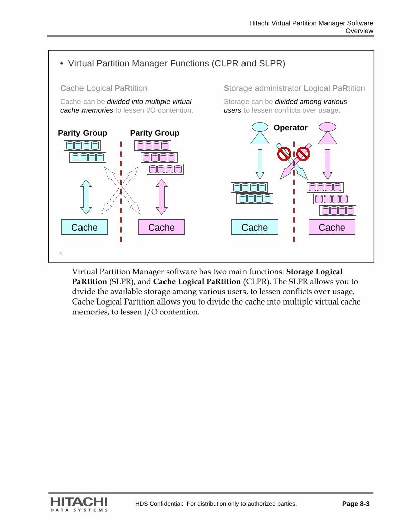
Hitachi Virtual Partition Manager Software Overview
HDS Confidential: For distribution only to authorized parties. Page 8-3
4
• Virtual Partition Manager Functions (CLPR and SLPR)
Cache Logical PaRtitionCache can be divided into multiple virtual cache memories to lessen I/O contention.
Storage administrator Logical PaRtitionStorage can be divided among various users to lessen conflicts over usage.
Cache Cache
Parity Group Parity Group
Cache
Operator
Cache
Virtual Partition Manager software has two main functions: Storage Logical PaRtition (SLPR), and Cache Logical PaRtition (CLPR). The SLPR allows you to divide the available storage among various users, to lessen conflicts over usage. Cache Logical Partition allows you to divide the cache into multiple virtual cache memories, to lessen I/O contention.

Hitachi Virtual Partition Manager Software Overview
Page 8-4 HDS Confidential: For distribution only to authorized parties.
5
LUN
LDEV
Company A Company B
・・・・
Company C Company D
Cache (Common to all users)
Heavy load
• Cache Logical Partition Overview– Storage Administrator (SA, the chief) performs all the settings and
assigns resources (ports, parity groups, and cache) to all companies – Storage Partition Administrator (SPA) manages only assigned
resourcesBecause of a higher I/O rate, this user can slow down the performance of the other users.
The Universal Storage Platform V and Universal Storage Platform VM can connect multiple hosts, and can be shared by multiple users, such as different departments or even different companies. This can cause conflicts among the various users. For example, if a particular host issues a lot of I/O requests, the I/O performance of other hosts may decrease. If various administrators have different storage policies and procedures or issue conflicting commands, these can cause difficulties.
Problem: Due to the heavy load in Company A, data in other companies (Company B/C/D) is excluded from the cache memory. As a result, the cache hit rate decreases, and the performance of application degrades.
LUN stands for logical unit, and LDEV stands for logical device

Hitachi Virtual Partition Manager Software Overview
HDS Confidential: For distribution only to authorized parties. Page 8-5
6
• Cache Logical Partition– Cache is divided (destaging is still performed on the total cache)– Logically assigns the size of cache (minimum 4GB, increasing by 2GB
increments)– Host I/O is independent– Company A is throttled back, performance increases at Companies B–DNote: Virtual Partition Manager software is not a performance tool.
LDEV
Company A Company B
・・・・
Company D
Cache Cache Cache Cache
Company C
Storage Administrator
Heavy load
LUN
Cache Logical Partition allows you to divide the cache into multiple virtual cache memories, to lessen I/O contention. A user of each server can perform operations without considering the operations of other users. Even if the load becomes heavy in Company A, the operations in Company A do not affect other companies operations.

Hitachi Virtual Partition Manager Software Storage Logical Partition
Page 8-6 HDS Confidential: For distribution only to authorized parties.
Storage Logical Partition
Storage Management Logical PaRtition =SLPR
In an advanced SAN environment, storages are consolidated and managed independently of each system management.
However, many customers would like to release some of the operations, such as adding capacity, to each System Administrator. SLPR makes this function possible.
8
• Maximum 32 SLPRs per array• Resources for SLPR
– One or more CLPRs – One or more Target ports (ex. CL1-A to SLPR1, Max. 256 ports per array)
– One or more control unit (CU) numbers and SSIDnumbers (Multiple SLPRs cannot share the same CU/SSID.)
SLPR0
CLPR1 CLPR0CLPR2 = Non partitioned cache area
SLPR2SLPR1
SLPR definitionis provided byStorageNavigator program
Target Port

Hitachi Virtual Partition Manager Software Storage Logical Partition
HDS Confidential: For distribution only to authorized parties. Page 8-7
9
Storage System
SLPR 1 SLPR 2
: Volume
Cache Memory
CLPR 1
CLPR 2
CLPR 3
Legend:
: Access
Port A Port B Port C
Storage System Administrator
Enterprise A
Hosts Hosts
Enterprise B
Storage System Administrator
A Universal Storage Platform V or VM can be shared among several groups that may have different storage administrators. This can cause problems if those administrators have differing or conflicting storage procedures, or if two or more administrators attempt to perform operations on the same logical volume, such as LUN Expansion (LUSE) or Virtual LVI/LUN (VLL). The storage logical partition function can allocate the storage system resources into two or more virtual storage systems, each of which can be accessed only by the storage administrator, the storage partition administrator for that storage logical partition, and the users for that partition. You can create up to 32 storage logical partitions in one storage system, including the default SLPR 0. There is no maximum or minimum size for a SLPR.
The storage system diagrammed above is divided into two virtual partitions, so that the storage administrator of each storage logical partition can only access that partition.

Hitachi Virtual Partition Manager Software Cache Logical Partition
Page 8-8 HDS Confidential: For distribution only to authorized parties.
Cache Logical Partition
Cache Logical PaRtition = CLPR
This feature aims at preventing partitions from affecting each other’s performance (as much as possible) by assigning a desirable cachesize to each logical partition.
11
Cache Cache
Host A Host B Host A Host B
If Host B load is low, Host A can use a large portion of cache.
Although Host B load is low, Host A cannot use the cache assigned to CLPR of Host B.
• Purpose of CLPR– To prevent logical partitions from affecting each other’s performance – Not the effective use of cache in the entire system

Hitachi Virtual Partition Manager Software Cache Logical Partition
HDS Confidential: For distribution only to authorized parties. Page 8-9
12
Storage System
Legend:
: Host I/O
Storage Administrator
Cache Memory (128 gigabytes)
CLPR1 (40 gigabytes)
Parity group 1-1
: Administration
Host of Branch A
Parity group 1-2 Parity group 1-3
CLPR2 (40 gigabytes))
CLPR3 (40 gigabytes)
Host of Branch B Host of Branch C
If one disk storage system is shared with multiple hosts, and one host reads or writes a large amount of data, read and write data can require enough of the cache memory to affect other users. The cache logical partition function creates two or more virtual cache memories, with each allocated to a different host. This prevents contention for cache memory. You can create up to 32 cache logical partitions in one storage system, including the default CLPR 0 .
The above figure illustrates the use of cache memory within a corporation. In this example, the cache memory is partitioned into three segments of 40GB each, which are each allocated to a branch office. The host of branch A has a heavy I/O load. Because the cache memory is partitioned, that heavy I/O load does not impact the cache memory for the other two branches.

Hitachi Virtual Partition Manager Software Access Roles
Page 8-10 HDS Confidential: For distribution only to authorized parties.
Access Roles
13
• Storage Administrator (SA) has access and authority over the entire storage system.
• Storage Partition Administrator (SPA) has access and authority over only a partition of the storage system, as assigned by the SA.
SA authority and accessextends to the entire Storage System
SPA authority and access extends onlyto the partition

Hitachi Virtual Partition Manager Software Supported Functions for SPA
HDS Confidential: For distribution only to authorized parties. Page 8-11
Supported Functions for SPA
14
• Open volume only – Mainframe volumes can be assigned only to SLPR0.– Mainframe volumes can be assigned to all CLPRs(CLPR0-31).
• Resource Manager utility package (Storage Navigator)• System Information (Read-only)• LUN Manager
– Port– Authentication
• LUN Expansion/VLL – Hitachi Volume Shredder feature
• Cache Residency• Performance Manager
– Performance Monitor• Data Retention Utility• Security
– Account

Hitachi Virtual Partition Manager Software Concept
Page 8-12 HDS Confidential: For distribution only to authorized parties.
Concept
15
• SLPR0 (Storage Partition) and CLPR0 (Cache Partition) are default• SLPR0 is a pool of logical cache partitions and ports• CLPR0 is a pool of all cache and all the parity groups in the
storage system• Only a Storage Administrator can access SLPR0 and CLPR0• A Storage Administrator creates the other SLPRs and CLPRs
– Storage Partition Administrators manage their SLPRs
SLPR0
CLPR0
SLPR0 (Storage Administrator Manages)CLPR1 CLPR2 CLPR4 CLPR0(Pool)CLPR2
SLPR0 (Pool)SLPR1 SLPR2 SLPR3CLPR1 CLPR2 CLPR4 CLPR0
(Pool)CLPR5CLPR3
If no storage partition operations have occurred, the storage system will have Storage Logical Partition 0 (SLPR0), which is a pool of all of the resources of the storage system (For example, cache logical partitions and ports). SLPR0 will also contain Cache Logical Partition 0 (CLPR0), which is a pool of all of the cache and all parity groups in the storage system. The only users who have access to SLPR0 and CLPR0 are the Storage Administrators.
1. CLPR0/SLPR0 always exists and cannot be removed.
2. CLPR0 always belongs to SLPR0.
3. CLPR0 is a pool area of cache and PG.
4. Only the Storage Administrator can use SLPR0. The Partitioned Storage Administrators manage other SLPRs.

Hitachi Virtual Partition Manager Software Storage Administrator and Storage Partition Administrator
HDS Confidential: For distribution only to authorized parties. Page 8-13
Storage Administrator and Storage Partition Administrator
16
• Administrator Access– Administrators are assigned using the Control Panel of the Storage
Navigator program (Option button)
Storage Administrator
Storage System
SLPR 1 SLPR 2
Cache memory
CLPR 1 CLPR 2 CLPR 3
StoragePartitionAdministrator
Not available
Port A Port B Port C
StoragePartitionAdministrator• One SA
• Many SPAs
The administrator access for the Universal Storage Platform V or VM is divided into two types:
Storage Administrators manage the entire storage system and all of its resources. Storage Administrators can create and manage storage logical partitions and cache logical partitions, and can assign access permission for Storage Partition Administrators. Only the Storage Administrators can access Storage Logical Partition 0 (SLPR0) and Cache Logical Partition 0 (CLPR0).
Storage Partition Administrators can view and manage only the resources that have been assigned to a specific storage logical partition.

Hitachi Virtual Partition Manager Software Storage Administrator and Storage Partition Administrator
Page 8-14 HDS Confidential: For distribution only to authorized parties.
17
Storage Administrator (SA):• Can assign or allocate storage to
new partitions• Allocate resources for remote
replication (through Sun TrueCopy Remote Replication software)
• Can map external storage to CU:LDEV and assign SLPR/CLPR
• Service Processor (SVP) modify authority
Storage Partition Administrator (SPA):• Can allocate storage only within
assigned partition• Can create replication within SLPR
(through ShadowImage Replication software volumes)
• No access to external storage, unless provided by SA
• SVP modify authority
Notes: An SPA can create ShadowImage pairs using the Command Control Interface only. They cannot create the pairs using Storage Navigator program GUI .

Hitachi Virtual Partition Manager Software Storage Administrator and Storage Partition Administrator
HDS Confidential: For distribution only to authorized parties. Page 8-15
18
• Only Storage Administrator can define TrueCopy Remote Replication software
Storage Administrator
SLPR0CLPR1 CLPR0CLPR2
SLPR2SLPR1
Partition Admin/User
Initiator Port
StorageTek 9900V/9985VNumber One
SLPR0
CLPR1 CLPR0CLPR2
SLPR2SLPR1 RCU Target Port
StorageTek 9900V/9985VNumber Two
Port Shared
by allSLPRs
Port Shared
by allSLPRs

Hitachi Virtual Partition Manager Software Storage Administrator and Storage Partition Administrator
Page 8-16 HDS Confidential: For distribution only to authorized parties.
19
• Storage Partition Administrator can define ShadowImage Replication software volumes within its own SLPR
• Storage Administrator can perform a copy operation using volumes in multiple SLPRs.
SLPR0
CLPR1 CLPR0CLPR3
SLPR2SLPR1
Storage Administrator
Storage Partition Administrator for SLPR1
CLPR2
The SA can perform a copy operation using volumes in multiple SLPRs. However, this operation is not recommended for the following reasons:
SPA can not operate ShadowImage software on this pair. If the SA executes a Quick Restore on this pair, the SPA can not operate Resource Manager software on volumes of this pair.

Hitachi Virtual Partition Manager Software Storage Administrator and Storage Partition Administrator
HDS Confidential: For distribution only to authorized parties. Page 8-17
20
• Only a Storage Administrator can map external storage to CU:LDEV and assign SLPR/CLPR
SLPR1 SLPR2 SLPR0
Modular Storage Enterprise Storage
CLPR1 CLPR3
Target Port
ExternalPort
Data Flow
Mapping
External port belongs to SLPR0, and are shared by all SLPRs.StorageTek
9900V/9985V
CLPR2 CLPR0

Hitachi Virtual Partition Manager Software Storage Administrator and Storage Partition Administrator
Page 8-18 HDS Confidential: For distribution only to authorized parties.
21
• Storage Navigator ProgramStorage Administrator Screen Storage Partition Administrator ScreenSA sees all the resources SPA see only their resources
Resources are divided into each SLPR. In the Storage Administrator’s screen, all resources in all SLPRs are displayed. In the Storage Partition Administrator’s screen, only the resources in their own SLPR are displayed. Resources shared by all SLPRs are displayed in both Storage Administrator’s and Storage Partition Administrator’s screen.

Hitachi Virtual Partition Manager Software Storage Administrator and Storage Partition Administrator
HDS Confidential: For distribution only to authorized parties. Page 8-19
• The Universal Storage Platform V or VM allows several users to log into the system and put their session of Storage Navigator program in the Modify mode (multiple lock control).
• No one has a lock.
SLPR31
SVP Modify Authority
SLPR3SLPR2SLPR1
23
• Multiple Lock Control - Storage Administrator sets Modify Mode
Storage Partition Administrator for SLPR3 attempts to set Modify Mode and is blocked
Storage Administrator (SA) sets Modify Mode and blocks all other users from entering Modify Mode
Storage Administrator attempts to enter Maintenance Mode at the SVP and is blocked
SLPR31
SVP Modify Authority
SLPR3SLPR2SLPR1SA has Modify Authority for each SLPR

Hitachi Virtual Partition Manager Software Storage Administrator and Storage Partition Administrator
Page 8-20 HDS Confidential: For distribution only to authorized parties.
24
• Multiple Lock Control – Storage Partition Administrator sets Modify Mode
PSA for SLPR1 attempts to set Modify Mode and is blocked
Storage Administrator (SA) sets Modify Mode for SLPR1
Storage Administrator attempts to enter Maintenance Mode at the SVP and is blocked
SLPR31
SVP Modify Authority
SLPR3SLPR2SLPR1SA has Modify Authority for SLPR1
PSA for SLPR3 is allowed to set Modify Mode
Multiple Lock Control:
If the Storage Administrator has Modify mode then no one else can access volumes. However, if the Storage Partition Administrator for SLPR1 is in the Modify mode along with the Storage Partition Administrator in SLPR31, access is okay for the volumes in SLPR31 since they are the separate partitions.

Hitachi Virtual Partition Manager Software Features
HDS Confidential: For distribution only to authorized parties. Page 8-21
Features
25
• Virtual Partition Unit– Storage must be assigned on a full parity group boundary– Partial parity groups or LDEV assignment is not allowed
Parity Group
Parity Group
Logical Partition
Parity Group
Logical Partition
Parity Group
LDEV
Virtual Partition Unit:
Devices are assigned to a logical partition in units of parity group (not each LDEV, PDEV). The access load to an LDEV affects performance of other LDEVs in the same parity group. This is because each parity group has the access control information (for example, resource lock and queue table).

Hitachi Virtual Partition Manager Software Features
Page 8-22 HDS Confidential: For distribution only to authorized parties.
26
• Virtual Partition Image– Each partition has its own DCR and Sidefile memory area
• DCR = Dynamic Cache Residency• Sidefile is an area of Shared Memory used for Hitachi TrueCopy
Asynchronous software
VDEV(ECC Group)
Cache Memory
CLPR0 (pool of devices not defined in CLPR1-31)
Available resource capacity
SidefileDCR
used capacityAssigned resource capacity
SidefileDCR
used capacity
CLPR2CLPR1Assigned resource capacity
SidefileDCR
used capacity
Virtual Partition Image:
The content of each CLPR includes I/O cache, DCR and the Sidefile and is mapped to specific parity groups. The maximum size is 252GB.

Hitachi Virtual Partition Manager Software Features
HDS Confidential: For distribution only to authorized parties. Page 8-23
• SLPR Partitioning Definition– Maximum of 32 SLPRs per Universal Storage Platform V or VM
Resources for SLPR• One or More CLPRs• One or More Target ports are assigned to a SLPR
– Ports assigned to one SLPR cannot be assigned to another SLPR– Unassigned ports in the pool remain shared resources
• One or More Control Unit (CU) Numbers and SSID Numbers– Multiple SLPRs cannot share the same CU/SSID
Note: SLPR definition is performed using Storage Navigator program.
CLPR1
SLPR1 Target Port
CLPR2
SLPR2 Target Port SLPR0 (the resource pool)
CLPR0 = Non partitioned cache area
28
• Specifications
Supported if CLPR has minimum 6GBDCR11
All Open types supported by Universal Storage Platform V systems
RAID Level10
SupportedLUSE9
32Max number of CLPRs per SLPR8
All Open types supported by Universal Storage Platform V systems
Support emulation type7
1 – 16,384Change unit of VDEV per CLPR61 – 16,384Max number of VDEV per CLPR5
4GB – 256GBCLPR Capacity4Increase size by 2GBChange unit of CLPR3
Parity groupMinimum unit of CLPR232Maximum number of CLPRs1
ContentItem

Hitachi Virtual Partition Manager Software Configuration Change
Page 8-24 HDS Confidential: For distribution only to authorized parties.
Configuration Change
• Change Assigned Cache Size
• Device Movement
CLPR X CLPR X
CLPR Y CLPR Y
Cache Capacity Cache Capacity
Cache Capacity Cache Capacity
CLPR X CLPR X
CLPR Y CLPR Y
30
CLPR 0
CLPR Y
CLPR 0
CLPR Y
CLPR X
CLPR Y
CLPR X
CLPR Y
• Define/Release CLPR
• Combine/Divide CLPR

Hitachi Virtual Partition Manager Software Configuration Change
HDS Confidential: For distribution only to authorized parties. Page 8-25
31
• Configuration Change requires processing time.• Processing time depends on cache capacity for operation, device capacity
for operation, cache usage before operation, write pending ratio before operation, I/O load, and so on.
• As it may take several hours depending on the conditions, Sun Microsystems supports “progress display”.

Hitachi Virtual Partition Manager Software Control
Page 8-26 HDS Confidential: For distribution only to authorized parties.
Control
• It performs the inflow control by comparing the write pending threshold with the write pending rate of each CLPR.
• Therefore, even though the write pending rate of one CLPR is very high, other CLPR inflow control is not changed.
Host A Host B
WP WP
33
• It performs the destage process by comparing the write pending threshold with the write pending rate of the entire system.
• In the Default mode (mode 454 OFF), when the write pending rate of one CLPR is very high, other CLPR destage process is accelerated because it performs the destage process to use the highest write pending rate of all CLPR.
Host A Host B
Threshold for destageshared by ALL CLPRs

Hitachi Virtual Partition Manager Software Control
HDS Confidential: For distribution only to authorized parties. Page 8-27
34
Host A Host B
Threshold for destageshared by ALL CLPRs.
• It performs the destage process by comparing the write pending threshold with the write pending rate of the entire system.
• In the Special mode (mode 454 ON), when the average of the write pending rate of all CLPR is not high, specific CLPR destage process is not accelerated.
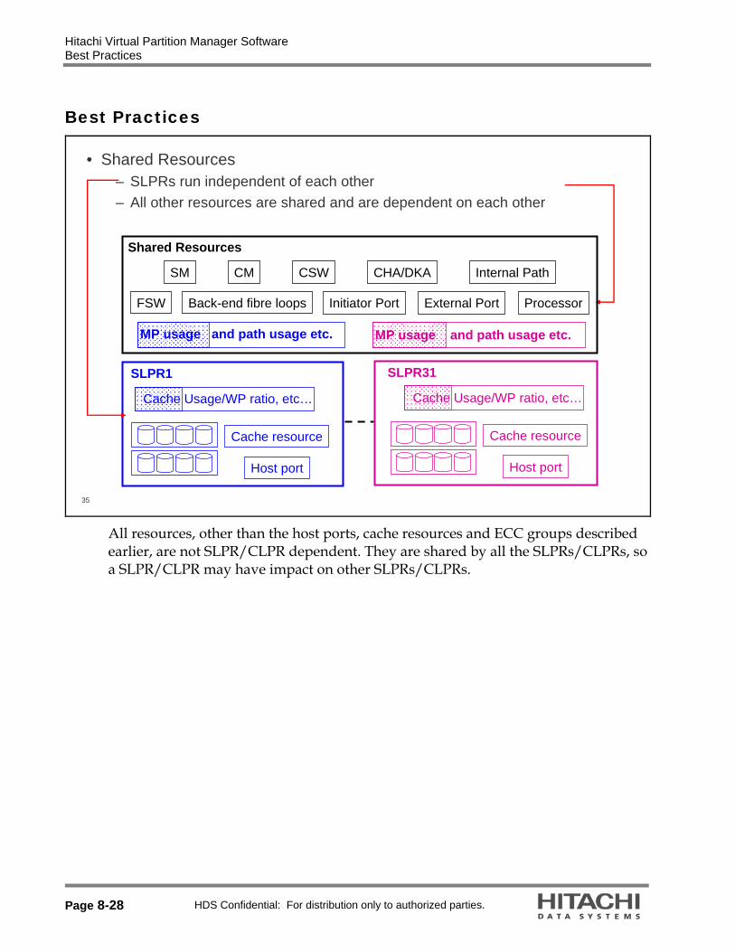
Hitachi Virtual Partition Manager Software Best Practices
Page 8-28 HDS Confidential: For distribution only to authorized parties.
Best Practices
35
• Shared Resources– SLPRs run independent of each other– All other resources are shared and are dependent on each other
Cache Usage/WP ratio, etc…
Cache resource
Host port
SLPR1
Cache Usage/WP ratio, etc…
Cache resource
Host port
SLPR31
Shared Resources
SM CM CSW CHA/DKA Internal Path
FSW Initiator Port External PortBack-end fibre loops Processor
MP usage and path usage etc.MP usage and path usage etc.
All resources, other than the host ports, cache resources and ECC groups described earlier, are not SLPR/CLPR dependent. They are shared by all the SLPRs/CLPRs, so a SLPR/CLPR may have impact on other SLPRs/CLPRs.

Hitachi Virtual Partition Manager Software Best Practices
HDS Confidential: For distribution only to authorized parties. Page 8-29
36
• Hi-Star™ Crossbar Switch Architecture Paths– All the internal paths are shared and cannot be divided among the SLPRs and
CLPRs
SM-path
CM-path (P-path)
CM-path (C-path)
SM SMSM SM
CHA CHADKA DKA
CSWCSW
Cache CacheCache Cache
Internal Paths cannot be divided for each SLPR/CLPR, because Hi-Star architecture paths are shared by all channel adaptors (CHAs) and disk adaptors (DKAs).

Hitachi Virtual Partition Manager Software Virtual Partition Manager Best Practices
Page 8-30 HDS Confidential: For distribution only to authorized parties.
Virtual Partition Manager Best Practices
37
• Disk Adaptor (DKA)(BED) Processors– You can design your CLPR configuration around the hardware configuration
R1 DKU
HDD HDDHDD HDDHDD HDDHDD HDD
HDD HDDHDD HDDHDD HDDHDD HDD
DKC
R0 DKU
HDD HDDHDD HDDHDD HDDHDD HDD
DKDKA
1st Pair
DKDKA
2nd Pair
DKDKA
3rd Pair
DKDKA
4th Pair
CLPR1 and CLPR2 share the same DKA pair: If the DKA load is high, the CLPRs affect each other’s performance.
CLPR1
CLPR2
CLPR3 and CLPR4 are on different DKA pairs: If the DKA load is high, the CLPRs do not affect each other’s performance.
CLPR3
CLPR4
The DKA(BED) processors are shared by all CLPRs, but you can divide the DKA processors for each CLPR.
Hitachi Virtual Partition Manager Software Operations
HDS Confidential: For distribution only to authorized parties. Page 8-31
Operations
38
• Virtual Partition Manager Operations Overview– Creating a storage logical partition– Migrating the resources in a storage logical partition– Creating a cache logical partition– Migrating the parity groups in a cache logical partition– Deleting a cache logical partition– Deleting a storage logical partition

Hitachi Virtual Partition Manager Software Functions
Page 8-32 HDS Confidential: For distribution only to authorized parties.
Functions
39
• License Key Panel Allows Partition Configuration Functions– Partition Definition (create Storage Logical Partitions first)– License Key Partition Definition (assign or allocate license capacity among
the various SLPRs second)
Click Go menu > Environmental Settings > Partition Definition.

Hitachi Virtual Partition Manager Software Creating an SLPR
HDS Confidential: For distribution only to authorized parties. Page 8-33
Creating an SLPR
40
To create a SLPR, right-click on the Subsystem folder and select Create SLPR.
Available resources in the storage system:16GB, 9 Parity Groups, and 16 Ports in this system.
To create a storage logical partition:
1. Launch Virtual Partition Manager, and change to Modify mode.
2. Click the Partition Definition tab. In the left navigation pane, right-click the Subsystem folder to display the popup menu.
3. Select Create SLPR. This will add a storage logical partition to the Logical Partition List. You can create up to 31 storage logical partitions in addition to SLPR0, either now or later.
4. Select the SLPR that you want to define from the Partition Definition panel. This will display the Storage Management Logical Partition panel.

Hitachi Virtual Partition Manager Software Creating an SLPR
Page 8-34 HDS Confidential: For distribution only to authorized parties.
41
Click on the new SLPR to select it Select desired CUs and/or SSIDs, click
the Add button and then click Apply.
To create a storage logical partition (continued):
5. Under Detail For SLPR for SLPR Name, enter the name of the selected SLPR. You can use up to 32 alphanumeric characters.
6. For CU, enter the CU numbers for the selected SLPR (00 - 3F). An asterisk (*) indicates that the CU is defined as an LDEV.
7. To add a CU to the SLPR, select the CU from the Available CU list, then click Add to move that CU to the CU list. You can select up to 64 CUs, whether or not those CUs are defined as LDEVs.
8. To delete CU from the specified SLPR, select the CU from the CU list and click Delete to return that CU to the Available CU list.
9. Available SSIDs are in SLPR0. In the SSID field, select an available SSID as follows:
1. In the From: box, enter the starting number of the SSID (0004 to FFFE).
2. In the To: box, enter the ending number of the SSID.
10. Click Apply to apply the settings. A progress bar is displayed.

Hitachi Virtual Partition Manager Software Migrating Resources in an SLPR
HDS Confidential: For distribution only to authorized parties. Page 8-35
Migrating Resources in an SLPR
42
• Migrating Resources to and from Storage Logical Partitions– Add a Port to the new SLPR from the pool (SLPR0)
• Select and expand SLPR0.• Select the desired port(s) and
then right-click and select Cut
The resources of a storage logical partition include cache logical partitions and ports, which can be migrated to another storage logical partition as needed. The only ports that can be migrated are Target ports and the associated network attached storage (NAS) ports are on the same channel adapter. Initiator ports, RCU Target ports and External ports cannot be migrated, and must remain in SLPR0. Notes:
LUs that are associated with a port in a particular SLPR must stay within that SLPR. LUs that are associated with a parity group in a particular SLPR must stay within that
SLPR. Parity groups containing NAS system LUs (LUN0005, LUN0006, LUN0008, LUN0009,
and LUN000A) must remain in SLPR0. NAS system LUs (LUN0000 and LUN0001) must belong to the same SLPR as the NAS
channel adapter. To migrate one or more resources: 1. Launch Virtual Partition Manager, and change to Modify mode. 2. Click the Partition Definition tab. In the left navigation pane, select an SLPR . The
Storage Management Logical Partition panel appears. 3. From the Storage Management Logical Partition Resource list, select one or more
CLPRs and/or ports to be migrated. Right-click to display the popup menu. Select Cut.
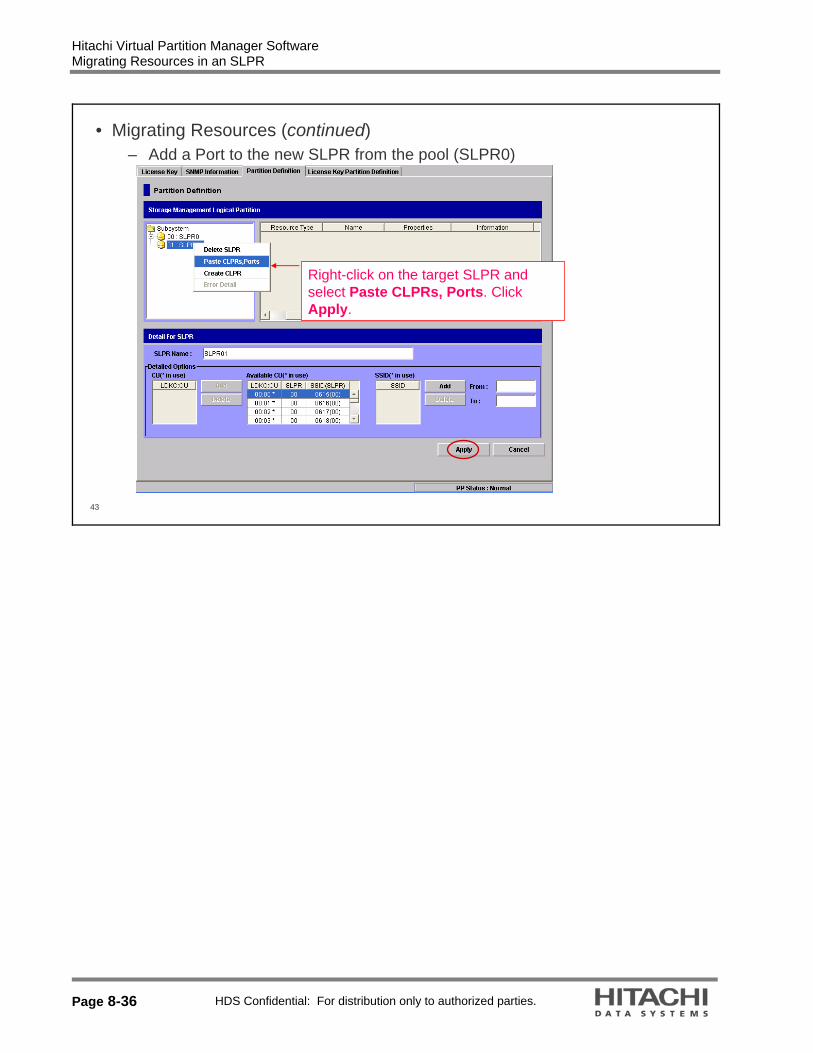
Hitachi Virtual Partition Manager Software Migrating Resources in an SLPR
Page 8-36 HDS Confidential: For distribution only to authorized parties.
43
• Migrating Resources (continued)– Add a Port to the new SLPR from the pool (SLPR0)
Right-click on the target SLPR and select Paste CLPRs, Ports. Click Apply.

Hitachi Virtual Partition Manager Software Creating a CLPR
HDS Confidential: For distribution only to authorized parties. Page 8-37
Creating a CLPR
44
Right-click on the target SLPR and select Create CLPR.
You must first have created one or more storage logical partitions before you can create a cache logical partition.
To create a cache logical partition:
1. Launch Virtual Partition Manager, and change to Modify mode.
2. Click the Partition Definition tab. Under Storage Management Logical Partition in the left navigation pane under Subsystem, right-click an SLPR.
3. In the popup menu, click Create CLPR. The new CLPR appears under the SLPR.
4. Select the newly created CLPR from the Partition Definition outline, to display the Cache Logical Partition pane.
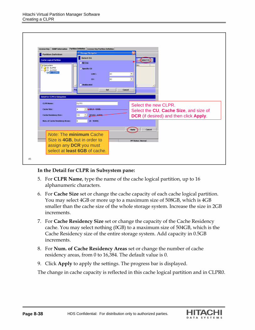
Hitachi Virtual Partition Manager Software Creating a CLPR
Page 8-38 HDS Confidential: For distribution only to authorized parties.
45
Select the new CLPR.Select the CU, Cache Size, and size of DCR (if desired) and then click Apply.
Note: The minimum Cache Size is 4GB, but in order to assign any DCR you must select at least 6GB of cache.
In the Detail for CLPR in Subsystem pane:
5. For CLPR Name, type the name of the cache logical partition, up to 16 alphanumeric characters.
6. For Cache Size set or change the cache capacity of each cache logical partition. You may select 4GB or more up to a maximum size of 508GB, which is 4GB smaller than the cache size of the whole storage system. Increase the size in 2GB increments.
7. For Cache Residency Size set or change the capacity of the Cache Residency cache. You may select nothing (0GB) to a maximum size of 504GB, which is the Cache Residency size of the entire storage system. Add capacity in 0.5GB increments.
8. For Num. of Cache Residency Areas set or change the number of cache residency areas, from 0 to 16,384. The default value is 0.
9. Click Apply to apply the settings. The progress bar is displayed.
The change in cache capacity is reflected in this cache logical partition and in CLPR0.

Hitachi Virtual Partition Manager Software Creating a CLPR
HDS Confidential: For distribution only to authorized parties. Page 8-39
46
• Add a Parity Group to the new CLPR from the pool (SLPR0)
Expand SLPR0, select CLPR0, right-click on the desired Parity Group(s) and select Cut.
47
• Add a Parity Group to the new CLPR from the pool (SLPR0)
Right-click on the Target CLPR and select Paste Parity Groups and then click Apply.

Hitachi Virtual Partition Manager Software Creating SLPR and CLPR Summary
Page 8-40 HDS Confidential: For distribution only to authorized parties.
Creating SLPR and CLPR Summary
48
Select the Subsystem folder.The pool (SLPR0) now contains 12GB, 8 Parity Groups, and 14 Ports.SLPR01 contains 4GB, 1 Parity Group, and 2 Ports.

Hitachi Virtual Partition Manager Software Deleting a CLPR
HDS Confidential: For distribution only to authorized parties. Page 8-41
Deleting a CLPR
49
If you delete a cache logical partition, any resources (For example, parity groups) will be automatically returned to CLPR0. CLPR0 cannot be deleted.
To delete a cache logical partition:
1. Launch Virtual Partition Manager, and change to Modify mode.
2. Click the Partition Definition tab.
3. Select a CLPR from the Subsystem tree. This displays the Cache Logical Partition pane.
4. Right-click the CLPR that you want to delete and select Delete CLPR in the popup menu. The selected CLPR is deleted from the tree.
5. Click Apply to apply the settings. The progress bar is displayed.

Hitachi Virtual Partition Manager Software Deleting an SLPR
Page 8-42 HDS Confidential: For distribution only to authorized parties.
Deleting an SLPR
50
If you delete a storage logical partition, any resources in that storage logical partition will be automatically returned to SLPR0. SLPR0 cannot be deleted.
1. Launch Virtual Partition Manager, and change to Modify mode.
2. Click the Partition Definition tab.
3. Select an SLPR from the panel to display Storage Management Logical Partition pane.
4. In the Subsystem tree, right-click the storage logical partition that you want to delete. This will display the Delete SLPR popup menu.
5. Select Delete SLPR.
6. Click Apply to apply the settings. The progress bar is displayed.

Hitachi Virtual Partition Manager Software SLPR and CLPR User IDs
HDS Confidential: For distribution only to authorized parties. Page 8-43
SLPR and CLPR User IDs
51
Click Go > Security > Account.

Hitachi Virtual Partition Manager Software SLPR and CLPR User IDs
Page 8-44 HDS Confidential: For distribution only to authorized parties.
52
• Add a Storage Partition Administrator (SPA)– Under Account, select 01-SLPR01 and right-click for new entry.– Enter the User ID and Password.
53
• Add a Storage Partition Administrator (continued)– Choose the SPA roles and functions and then click Apply.

Hitachi Virtual Partition Manager Software Program Products (PP) Licensing Type
HDS Confidential: For distribution only to authorized parties. Page 8-45
Program Products (PP) Licensing Type
54
• License capacity is assigned to each SLPR– Cache Residency Manager feature– Data Retention Utility– Open Volume Management– LUN Manager– Performance Monitor feature– Storage Navigator program– Java API– Volume Shredder software
• License capacity for the entire system or usable capacity

Hitachi Virtual Partition Manager Software PP Licensing Scheme
Page 8-46 HDS Confidential: For distribution only to authorized parties.
PP Licensing Scheme
55
1. Storage Administrator installs PP key to disk controller (DKC)
SLPR0
CLPR1 CLPR0CLPR2
SLPR2SLPR1
50TB20TB10TB
PP 80TB
20TB10TB
Install PP
SLPR0
CLPR1 CLPR0CLPR2
SLPR2SLPR1
50TB20TB10TB
PP 80TB
50TB
Partition Admin/User
Partition Admin/User
2a. Administrator can assign the license capacity to each SLPRStorage Administrator
Storage Administrator
2b. SA can assign license capacity to specific SLPR only
3. Non-partitioned System: Same operation image as current PP
SLPR0
CLPR1 CLPR0CLPR2
SLPR2SLPR1
50TB20TB10TB
PP 10TB
10TB
PP Installation
SLPR0
CLPR0
50TB
PP 50TB
Storage Administrator
50TBAutomatically assigned to SLPR0
Storage Administrator
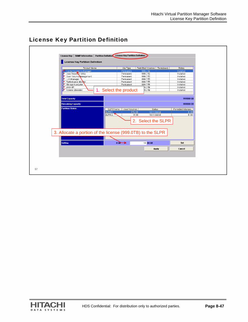
Hitachi Virtual Partition Manager Software License Key Partition Definition
HDS Confidential: For distribution only to authorized parties. Page 8-47
License Key Partition Definition
57
1. Select the product
2. Select the SLPR
3. Allocate a portion of the license (999.0TB) to the SLPR

Hitachi Virtual Partition Manager Software
Page 8-48 HDS Confidential: For distribution only to authorized parties.

HDS Confidential: For distribution only to authorized parties. Page 9-1
9. Hitachi Data Retention Utility Overview
Module Objectives
2
• Upon completion of this module, the learner should be able to: – Describe the purpose of the Hitachi Data Retention Utility– List the three access attributes that can be assigned for the Data Retention
Utility– Identify key features of the Data Retention Utility panels– Describe how to set access attributes to a logical volume using the Data
Retention Utility– Describe the restrictions for logical volumes that can be used with the Data
Retention Utility – Describe the purpose and behavior of the Retention Term setting

Hitachi Data Retention Utility Overview Overview
Page 9-2 HDS Confidential: For distribution only to authorized parties.
Overview
3
• Purpose of the Data Retention Utility– Protects data in your storage system from I/O operations performed at open
systems hosts– Enables you to assign an access attribute to each logical volume– Allows you to use a logical volume as a Read-Only volume– Enables you to protect a logical volume against both read and write
operations
• Caution: Data Retention Utility should be used with extreme caution! – Mistakes can have long term consequences for the selected LDEVs!!
Data Retention Utility also offers the capability to freeze the data activity within the environment. This will ensure that logical volumes with an expired retention period will not be returned to the Read/Write mode. This facility is called Expiration Lock (also referred to as Audit Lock).

Hitachi Data Retention Utility Overview Overview
HDS Confidential: For distribution only to authorized parties. Page 9-3
4
• Access Attributes– Read/Write:
• If a logical volume has the Read/Write attribute, open systems hosts can perform both read and write operations on the logical volume.
– Read Only:• If a logical volume has the Read Only attribute, open systems hosts can
only perform read operations on the logical volume.
– Protect:• If a logical volume has the Protect attribute, open systems hosts cannot
access the logical volume. The open systems hosts cannot performeither read nor write operations on the logical volume.
By default, all the open systems volumes are subject to read and write operations by open systems hosts. For this reason, data on the open systems volumes might be damaged or lost if an open systems host performs erroneous write operations. Also, confidential data on the open systems volumes might be stolen if a malicious operator performs read operations on open systems hosts. However, if you use Data Retention Utility, you can use logical volumes as Read-Only volumes to protect the volumes against write operations. You can also protect logical volumes against both read and write operations. The Data Retention Utility enables you to restrict read operations and write operations on logical volumes and prevents data from being damaged, lost and stolen. To restrict read and write operations, you must assign an access attribute to each logical volume. Data Retention Utility enables you to assign one of the following access attributes to each logical volume:
Read/Write: All open-systems volumes have the Read/Write attribute by default. Read Only: If a logical volume has the Read-Only attribute, open systems hosts can perform read operations but cannot perform write operations on the logical volume. You cannot use Hitachi replication software (such as ShadowImage Replication software or TrueCopy Remote Replication software) to copy data to logical volumes that have a Read-Only attribute.
Protect: If a logical volume has the Protect attribute, the open systems hosts cannot access the logical volume. Open systems hosts cannot perform read nor write operations on the logical volume. You cannot use Hitachi copy software to copy data to logical volumes that have the Protect attribute.
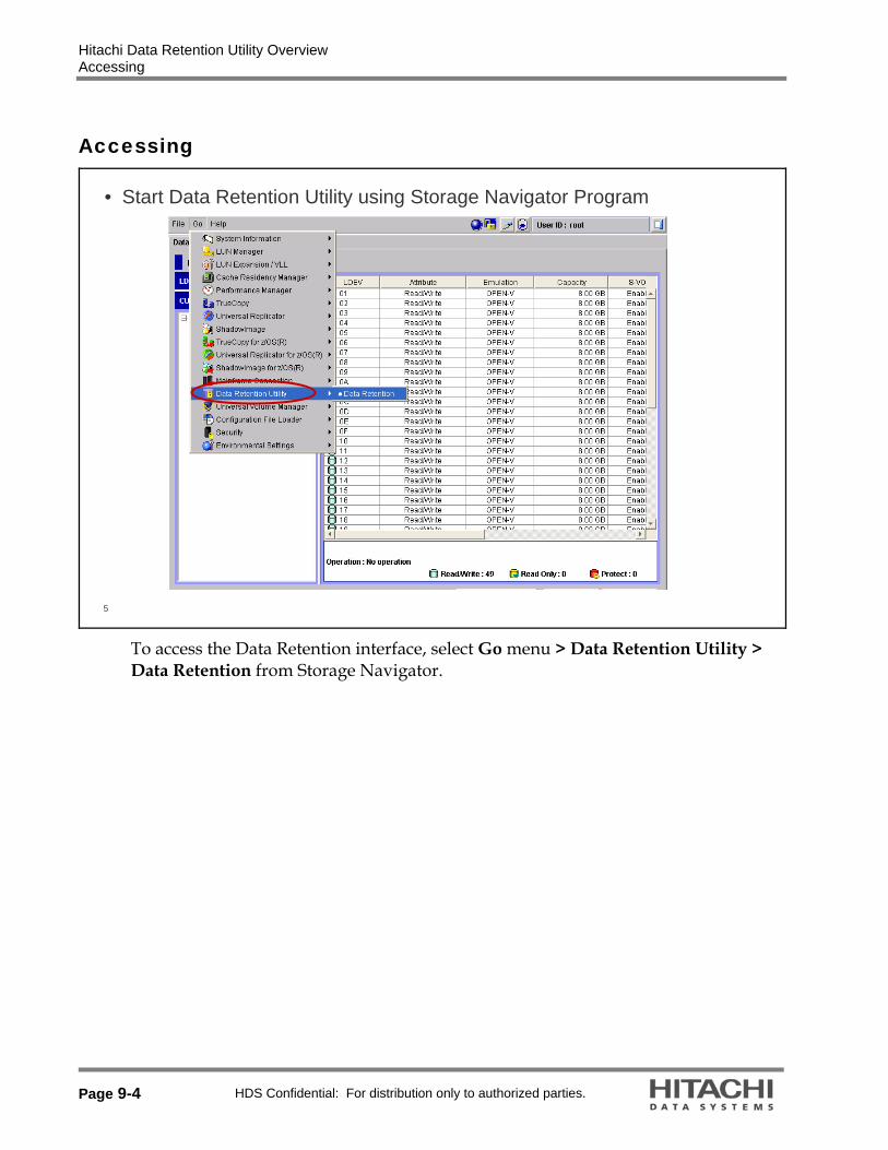
Hitachi Data Retention Utility Overview Accessing
Page 9-4 HDS Confidential: For distribution only to authorized parties.
Accessing
5
• Start Data Retention Utility using Storage Navigator Program
To access the Data Retention interface, select Go menu > Data Retention Utility > Data Retention from Storage Navigator.

Hitachi Data Retention Utility Overview Graphical User Interface
HDS Confidential: For distribution only to authorized parties. Page 9-5
Graphical User Interface
6
The volume list column headings are:
LDEV: Displays volume numbers
If # is displayed to the right of a volume number, the volume is an external volume. If V is displayed to the right of a volume number, the volume is a virtual volume. If X is displayed to the right of a volume number, the volume is a virtual volume for Dynamic Provisioning software.
Attribute: Indicates the access attribute of each volume.
To assign the access attribute to a volume, you can also use Command Control Interface (CCI).
Emulation: Displays volume emulation types. Capacity: Displays the capacity of each volume. The unit is gigabytes (GB) and the capacity is shown to two decimal places.
S-VOL: Indicates whether each volume can be specified as a secondary volume, which is a copy destination volume for Universal Storage Platform V or VM copy operations.

Hitachi Data Retention Utility Overview Graphical User Interface
Page 9-6 HDS Confidential: For distribution only to authorized parties.
Reserved: Indicates whether Command Control Interface (CCI) or Storage Navigator can be used to make LU path settings and command device settings.
A hyphen (-) indicates that CCI and Storage Navigator can be used to make LU path settings and command device settings. LUN Manager is required when you use Storage Navigator to make these settings.
CCI indicates that CCI can be used to make LU path settings and command device settings, but Storage Navigator cannot be used to do so.
Retention Term: This column displays the period (in days) when you are prohibited from changing access attribute to Read/Write. For example, if 500 days is displayed, attempts to change access attribute to Read/Write are prohibited in the next 500 days. If Unlimited is displayed, the retention term is extended unlimitedly.
If the retention term is 0 days, you can change access attribute to Read/Write. During the retention term, you can change Read-Only to Protect, or vice versa.

Hitachi Data Retention Utility Overview Graphical User Interface
HDS Confidential: For distribution only to authorized parties. Page 9-7
7
• CU List— Control Unit list
Indicates the number of logical volumes that have the Read/Writeattribute
Indicates the number of logical volumes that have the Read Onlyattribute
Indicates the number of logical volumes that have the Protect attribute
Difference between Storage Administrator and Storage Partition Administrator
A user who manages the whole storage system is called Storage Administrator. When the resources of the storage system are partitioned by Virtual Partition Manager software, a group of virtually divided resources is called Storage Logical Partition (SLPR). A user who manages the SLPR is called a Storage Partition Administrator.
While the Storage Administrator can set access attribute to the logical volumes in any control units (CUs) in the storage system, the Storage Partition Administrator can set access attribute only to the logical volumes in CUs in the SLPR the Storage Partition Administrator manages. Therefore, if you are a Storage Partition Administrator and using the Data Retention Utility panel only, the CUs in your SLPR are displayed on the panel. The CUs in the SLPRs which are managed by the other Storage Partition Administrators are not displayed.

Hitachi Data Retention Utility Overview Restrictions for Logical Volumes
Page 9-8 HDS Confidential: For distribution only to authorized parties.
Restrictions for Logical Volumes
8
• Logical Volumes for which you cannot change the Access Attribute – Logical Volumes other than the following emulation types:
• OPEN-3• OPEN-8• OPEN-9• OPEN-E
– Logical volumes that are configured as Command Devices– Logical Volumes that are specified as TrueCopy Remote Replication
synchronous volumes (S-VOLs)– Logical volumes that are specified as ShadowImage Replication volumes (S-
VOLs)– Logical Volumes that are reserved for Volume Migration software
• OPEN-K• OPEN-L• OPEN-M• OPEN-V
LU stands for Logical Unit S-VOL stands for secondary volume

Hitachi Data Retention Utility Overview Access Attribute
HDS Confidential: For distribution only to authorized parties. Page 9-9
Access Attribute
• Access Attribute Characteristics
Number of days that prohibit changing attribute to Read/Write.If Unlimited is displayed, you cannot change the attribute.
Mode assigned by the CCI (see User’s guide)
Indicates if volume can be used as asecondary volume
Hyphen (-):CCI or Storage Navigatorprogram can modify settings
CCI: Only CCI can modify settings
LDEV Attribute Emulation Capacity S-VOL Reserved Retention Term Paths Mode
00 Read/Write OPEN-V 58.59 GB Enable - - 0 -
01 Read Only OPEN-V 58.59 GB Disable - 2190 days 0 -
02 Protect OPEN-V 58.59 GB Disable - 0 days 0 Inv
LDEV: Displays logical device numbers that are indicated as Read/Write (Blue), Read
Only (Yellow) or Protect (Red). Attribute: Indicates the access attribute of each logical volume. Emulation: Displays volume emulation types. Capacity: Displays the capacity of each logical volume. The unit is gigabytes (GB). S-VOL: Indicates whether each logical volume can be specified as a secondary volume. Reserved: Indicates whether Command Control Interface (CCI) or Storage Navigator
program can be used to make settings. Hyphen (-): Indicates that CCI and Storage Navigator program can be used to make
LU path settings and command device settings. CCI: Indicates that CCI can be used to make settings but Storage Navigator program
cannot be used to do so. Paths: Displays the number of LU paths to each logical volume. Retention Term: Displays the period (in days) when you are prohibited from changing
access attribute to Read/Write. If Unlimited is displayed, you cannot change the access attribute anymore.
Mode: Displays the mode that the Command Control Interface user assigns to the logical volume.
Zer: Indicates that Zero Read Capacity mode is assigned to the logical volume and it will be reported as zero.
Inv: Indicates that Invisible mode is assigned to the logical volume. Zer/Inv: Indicates that both Zero Read Capacity mode and Invisible mode are
assigned to the logical volume. - (a hyphen): Indicates that no mode is assigned by CCI to the logical volume

Hitachi Data Retention Utility Overview Expiration Lock
Page 9-10 HDS Confidential: For distribution only to authorized parties.
Expiration Lock
10
• Overview– If you Enable Expiration Lock, attempts to change access attribute from Read-
Only or Protect to Read/Write will fail even after the retention term expires.
Expiration Lock implements stronger protection on logical volumes.
Disable -> Enable: When this button is displayed, expiration lock is disabled. You can change access attribute to Read/Write when the retention term is over (that is when Retention Term displays 0 days). If you click this button, Expiration Lock is enabled. This is the default.
Enable -> Disable: When this button is displayed, expiration lock is enabled. You cannot change access attribute to Read/Write even when the retention term is over (that is even when Retention Term displays 0 days). If you click this button, expiration lock is disabled.

Hitachi Data Retention Utility Overview Term Setting
HDS Confidential: For distribution only to authorized parties. Page 9-11
Term Setting
11
• Overview– Term setting enables you to specify a retention term, which is a period when
attempts to change access attribute to Read/Write are prohibited.– Range: Years = 0 – 60, Days = 0 – 21,900
Term: You can specify a retention term in years and days. The range for years is 0 to 60, where a year is 365 days. The range for days is 0 to 21900. For example, if 10 years 5 days or 0 years 3655 days is specified, the access attribute of the logical volume cannot be changed to Read/Write in the next 3,655 days.
Unlimited: Extends the retention term indefinitely.
OK: This button closes the Term Setting panel and applies settings in the Term Setting panel to the Data Retention panel. Note that this button does not apply the settings to the storage system. To apply the settings to the storage system, you must click Apply in the Data Retention panel.

Hitachi Data Retention Utility Overview Changing Access Attributes
Page 9-12 HDS Confidential: For distribution only to authorized parties.
Changing Access Attributes
12
• Procedure for Changing Access Attributes of Logical Volumes
Notes: R/W indicates Read/Write. R/O indicates Read Only. Pro indicates Protect. The blue arrow -> indicates that the access attribute will change. For example,
R/W -> R/O indicates that the access attribute will change from Read/Write toRead Only. Also, R/W -> Pro indicates that the access attribute will change from Read/Write to Protect.
To change access attributes of logical volumes: 1. Ensure that you are in the Modify mode. 2. In the Data Retention panel, select a CU image from the CU list to display a list of logical
volumes in the specified CU image. Access attributes are displayed on the right of logical volume names.
3. Select a logical volume whose access attribute you want to change and right-click it. Note: If you want to assign the same access attribute to all logical volumes in the list, click the button at the upper-right corner of the list. All logical volumes in the list will be selected.
4. From the pop-up menu, select Attribute to display a submenu. Then, select the desired access attribute from the submenu. If you select Read Only or Protect, you must also take the following steps:
In the Term Setting panel, specify the retention term. If you want to extend the retention term indefinitely, select Unlimited.
Note: If you select Unlimited, you will need to ask the maintenance personnel to change the retention term when you wish to change it. 5. Click OK to close the Term Setting panel. The logical volume is displayed in italics and
in blue when the access attribute changes. The volume icon also changes when the access attribute changes.
6. Click Apply in the Data Retention panel. A message appears and asks whether you want to apply the settings to the storage system.
7. Click OK. The settings are applied to the storage system.

HDS Confidential: For distribution only to authorized parties. Page 10-1
10. Mainframe Considerations
Module Objectives
2
• Upon completion of this module, the learner should be able to: – Identify the software compatible with mainframe.

Mainframe Considerations Mainframe Compatibility
Page 10-2 HDS Confidential: For distribution only to authorized parties.
Mainframe Compatibility
Hitachi has a long heritage, depth of knowledge, and continues to invest in mainframe compatibility features as well as new and innovative solutions for the mainframe environment.
4
• Software Compatible with Mainframe:– ST9900 Universal Replicator software for IBM® z/OS®
– Business Continuity Manager for z/OS– ST9900 TrueCopy Synchronous for z/OS– ST9900 TrueCopy Asynchronous for z/OS– Compatible Replication for IBM XRC– ST 9900 Data Retention Utility for z/OS– Resource Manager for z/OS– ST9900 ShadowImage for z/OS– Compatible Mirroring for IBM Flashcopy– Compatible PAV for IBM z/OS – Dataset Replication for z/OS– Database Replication for z/OS– Cross-OS File Exchange– Multiplatform Backup

Mainframe Considerations Business Continuity Manager
HDS Confidential: For distribution only to authorized parties. Page 10-3
Business Continuity Manager
• Features:– z/OS host software that provides centralized and unified management of:
• TrueCopy software and ShadowImage software • Real-time access to critical thresholds for problem avoidance• Auto-discovery eliminates errors and accelerates deployment • Automatic notification of key event completion provides greater control• Groups of copy volumes with common attributes using a single command • Standard REXX scripting to customize and automate• Real-time view of TrueCopy Async metrics• TrueCopy Reverse Resync
6
• Benefits:– Reduces the time-to-deploy and complexity of TrueCopy software and
ShadowImage software replication solutions, wherever they reside– Decreases staffing and training costs– Improves service levels and enhances business resilience and confidence– Addresses regulatory requirements for business continuity and data protection

Mainframe Considerations Dataset Replication for IBM z/OS
Page 10-4 HDS Confidential: For distribution only to authorized parties.
Dataset Replication for IBM z/OS
Creates and updates UserCat2 and then deletes it when no longer needed
VSN002VSN002DSN002DSN002
Secondary Secondary VolumeVolume
VSN001VSN001DSN001DSN001
Primary Primary VolumeVolume
VSN001VSN001DSN001DSN001
Primary Primary VolumeVolume
z/OSz/OS z/OSz/OS DRepDRep
UserCat 1UserCat 1 UserCat 1UserCat 1UserCat 2UserCat 2
• ShadowImage software utility for z/OS environments• Automatically performs Pairsplit • Creates, updates, and deletes required VTOC/Dataset/UserCat entries
before and after Pairsplit/ RESYNCH
LVD consists of two programs (HRULVDP and HRULVDX) and four functions (prepare function, volume divide function, volume unify function, and volume backup function). Use HRULVDP to execute the prepare function. Use the HRULVDX program to execute the volume divide function, the volume unify function, and the volume backup function. 1. To use a S-VOL for other jobs or file backup:
Execute the prepare function: LVD creates parameters for the volume divide function or the volume unify function.
Execute the volume divide function using the parameter which was created by the prepare function.
Use the S-VOL for other jobs or file backup, then execute the volume unify function using the parameter which was created by the prepare function.
LVD creates the following parameters for IDCAMS and AMASPZAP utilities to execute the volume divide function or the volume unify function. 1. VOLSER changing parameter in VTOC on a T-VOL for the volume divide
function. 2. Dataset changing parameter in VVDS/VTOC on S-VOL for the volume divide
function. 3. Parameter to create a user catalog for the S-VOL for the volume divide function. 4. Parameter to register a data set to a new user catalog for the S-VOL for the divide
function. 5. Parameter to delete the new catalog for the S-VOL for the volume unify function.
2. To use a S-VOL for physical volume backup: Execute the volume backup function. LVD does not use the parameter which was
created by the prepare function. You do not need to use the prepare function and the volume divide function.

Mainframe Considerations Database Replication of IBM z/OS
HDS Confidential: For distribution only to authorized parties. Page 10-5
Database Replication of IBM z/OS
8
VSN003
Database2Database1 Database3
Step 1
Step 2
VSN001VSN001DSN001DSN001
Primary VolumePrimary Volume
Table Space A
VSN002VSN002DSN002DSN002
Secondary Secondary VolumeVolume
Table Space A
VSN003VSN003DSN003DSN003
Secondary Secondary VolumeVolume
Table Space B
OS/390OS/390
Catalog 1 Catalog 2 DRep Copies Tablespace
DRep divide volume pair DRep divide volume pair and Rewrite Volser & and Rewrite Volser &
DSNDSN
• Simplifies use of ShadowImage software for DB2 OS/390 and z/OS environments
• Enables concurrent access to multiple copies of same tablespace information
• Eliminates costly errors associated with DB2 DSN1COPY utility
A ShadowImage software volume pair is created on the Universal Storage Platform. The Logical Volume Divider (LVD) utility is then used to divide (suspend) the volume pair, rewriting operating system management information on the target volume before varying the target volume online with a unique volume serial number (volser). This allows the data on the target volume to be accessed from any host system without creating application delays or suffering enqueue failures. After the successful completion of the LVD divide step, DBDivider can be executed and instructed to build DB2® utility DSN1COPY JCL. This JCL copies the DB2 Tablespace from the target volume to a previously defined empty DB2 Tablespace on another database volume. The newly loaded Tablespace can then be referenced within any DB2 subsystem where it has been previously defined. DBDivider derives the OS/390® Dataset Name used as input and output to DSN1COPY from control card information provided and determines the internal information (DBID, PSID, OBID) by reading the DB2 Control Tables (DB2® Catalog).

Mainframe Considerations Compatible Mirroring for IBM FlashCopy
Page 10-6 HDS Confidential: For distribution only to authorized parties.
Compatible Mirroring for IBM FlashCopy
9
NormalNormalprocessingprocessingcontinuescontinuesunaffectedunaffected
Copy ofCopy ofProductionProduction
VolumeVolume
ProductionProductionVolumeVolume
PointPoint--inin--time Copy for time Copy for parallel processingparallel processing
• Functionally compatible with FlashCopy host software• Manages ShadowImage software volumes with familiar DFSSMSdss,
Peer-to-Peer Remote Copy (PPRC) TSO commands
There is no down time or impact to production application.
QuickSplit command allows a copy to be available for read/write access immediately after QuickSplit command is entered.
Also, there is no impact to server processing, copy operation is completely handled within the storage system.
All ShadowImage software volumes are additionally RAID-protected. A disk failure or Automatic Error correction is handled completely transparently with no interruption.
All ShadowImage software volumes are completely protected by RAID at all times, regardless of the RAID type. An HDD failure or I/O error is recovered automatically and transparently to any application processing.
When a ShadowImage software consistency group is split, all I/Os are help within the storage system.

Mainframe Considerations Universal Storage Platform V Mainframe Compatibility
HDS Confidential: For distribution only to authorized parties. Page 10-7
Universal Storage Platform V Mainframe Compatibility
10
• Universal Storage Platform V or VM continues commitment to mainframe compatibility
• Universal Replicator for z/OS• Hitachi Business Continuity Manager for z/OS• TrueCopy Synchronous and Asynchronous for z/OS• Hitachi Compatible Extended Remote Copy (HXRC)• Data Retention Manager for z/OS• Hitachi In-System Replication for z/OS• Hitachi Compatible FlashCopy • Hitachi Compatible Parallel Access Volume (PAV) • Hitachi Cross-OS File Exchange• Hitachi Replication Manager software• Hitachi Tuning Manager software• Hitachi Device Manager software
Open Systems andMainframe management

Mainframe Considerations IBM and Hitachi
Page 10-8 HDS Confidential: For distribution only to authorized parties.
IBM and Hitachi
• IBM and Hitachi Sign Joint Technology Agreement – May 26, 2005 • Objective - Make it easier for customers to install and run both IBM and
Hitachi products in their environments• Hitachi licensed IBM’s eServer zSeries storage-related interface
technologies for use in Hitachi storage platforms as well as future technologies
• Announced plans for joint collaboration on product interoperability testing to support Hitachi storage compatibility with IBM zSeries mainframes
• Includes, but not limited to:– z/OS Global and Metro Mirroring– FlashCopy– Parallel Access Volumes (PAV)– GDPS
• Applies to Universal Storage Platform, including its OEM and co-branded variants
12
Sept 5, 2006 - Hitachi, Ltd. and Hitachi Data Systems Complete Storage Compatibility and Interoperability Testing for IBM Geographically Dispersed Parallel Sysplex® (GDPS®)TOKYO, Japan, and SANTA CLARA, California, September 5, 2006—Hitachi, Ltd. (NYSE: HIT / TSE: 6501) and its wholly owned subsidiary Hitachi Data Systems today announced successful completion of compatibility and interoperability testing of Hitachi storage supporting IBM Geographically Dispersed Parallel Sysplex®(GDPS®) solutions versions 3.2 and 3.3……..The companies successfully tested Hitachi storage support of GDPS version 3.2 and 3.3 using Enterprise System Connection™ (ESCON®), Fiber Connection (FICON®) and Fibre Channel Protocol (FCP) connectivity – for select configurations of IBM eServer zSeries® 800, 900 and 990 systems; System z9; and IBM 9672 G5 and G6 – running z/OS® 1.6 and z/OS® 1.7Hitachi and IBM successfully tested GDPS/PPRC-based functions including:
– Planned HyperSwap– Unplanned HyperSwap– HyperSwap Failover/Failback – Unplanned HyperSwap IOS Timing trigger – FlashCopy

Mainframe Considerations SATA Storage for DFSMShsm ML1
HDS Confidential: For distribution only to authorized parties. Page 10-9
SATA Storage for DFSMShsm ML1
13
• Expand the size of ML1 storage by using lower cost SATA storage• Turn off DFSMShsm data compression and reclaim expensive mainframe
processing cycles
Adaptable Modular Storage/Workgroup
Modular StorageML1
Volume 1Universal Storage
Platform V as Migration Level 0
High Performance, Production Platform
TapeML 2External Storage
Adaptable Modular Storage/Workgroup
Modular Storage SATA as Migration Level 1normally stored in
compressed format
Volume 1Volume 1Volume 2Volume 2
Volume 3Volume 3
Volume 2
Volume 3
Turn off data compression
ML0
MainframeLPAR LPAR
z/OSDFSMShsm
z/OS
Universal Storage
Platform V
Mainframe Usage Scenario

Mainframe Considerations SATA Storage for Tivoli
Page 10-10 HDS Confidential: For distribution only to authorized parties.
SATA Storage for Tivoli
14
• Expand the size of the Tivoli® intermediate Storage Pool by using lower cost SATA storage
• Keep more copies on disk for longer periods to improve data protection and enable faster restores from disk
Primary Primary Volume Volume
Universal Storage Platform V used for production applications that require high performance, high availability
BackupCopy 1
Mon 9PM
External StorageModular SATA
Volume Copy 2
Tue 9PM
Volume Copy 3
Wed 9PM
tapeExternal Attached Adaptable Modular Storage/Workgroup Modular Storage SATA storage used for large Tivoli Storage Pool
Archive to tape for long term storage or offsite vaulting
Tivoli Storage Pool
Mainframe
LPAR LPAR
Unixz/OS Tivoli StorageManager

Mainframe Considerations VTF™ Mainframe Benefits
HDS Confidential: For distribution only to authorized parties. Page 10-11
VTF™ Mainframe Benefits
15
• Software product enabling tape replacement • Runs as started task on OS/390 & z/OS
– JES2 or JES3• Simulates IBM compatible cartridge
tape devices and media– 3480/3490– 3590
• Entire process is fully transparent• Virtual tapes are stored on disk
– ESCON or FICON attached
Mainframe Server
ESCONor FICON
StorageVirtualization
Low Cost SATA Disks
Data written on VTF for mainframe (VTFM) virtual tapes is stored on disk. Remote disk mirroring and local copy technology may be used to protect and manage the VTFM disk pool just as any other data stored on disk. This is huge but it is not all: Hardware virtual tape systems may be thought of as “black boxes”. The user has little control of what happens within and behind these “black boxes”. VTFM, on the other hand, may be thought of as a “gray box” because it is pure IBM Multiple Virtual Storage (MVS) software and hardware. The user is in complete control of every aspect of what VTFM does and once it is set up little or no day-to-day management is required. VTFM executes as a started task, the disk VTFM uses is user selectable, the tape data sets that are written on VTFM virtual tapes are user selectable, the remote mirroring and the data that is remotely mirrored is user selectable. Because VTFM virtual tapes are stored on disk as standard MVS sequential disk data sets, the user can browse them and move them if necessary but users are not allowed deleting them. They are deleted in accordance with the users’ individual tape data set retention policy. Thus the “gray box”! Not completely transparent but being pure MVS the user can see into and control his VTFM virtual tape environment. VTFM improves tape application performance over native 3480 and 3490E tape drives and hardware virtual tape systems. This is an accomplished by using intelligent I/O algorithms and by placing virtual tape files on high performance disk. Higher CPU utilization - Tape I/O is buffered to full track and replaced by disk I/O. VTFM, in most cases reduces the number of physical I/Os being handled. This requires many less passes though data management code. Also the jobs are executed more rapidly causing a reduction in overhead for managing waiting jobs.

Mainframe Considerations
Page 10-12 HDS Confidential: For distribution only to authorized parties.

HDS Confidential: For distribution only to authorized parties. Page 11-1
11. Hitachi Storage Command Suite
Module Objectives
2
• Upon completion of this module, the learner should be able to: – Explain the Hitachi storage area management strategy– List the components of the Storage Management Command Suite– Describe the purpose and benefits of:
• Device Manager software• Tuning Manager software• Dynamic Link Manager software• Global Link Manager software• Tiered Storage Manager software• Protection Manager software• Storage Services Manager software
The following topics are covered in Part 2 of this Module- Storage Command Suite:
Tiered Storage Manager software Protection Manager software Storage Services Manager software

Hitachi Storage Command Suite Storage Management Command Suite
Page 11-2 HDS Confidential: For distribution only to authorized parties.
Storage Management Command Suite
3
Business ApplicationModules
Storage OperationsModules
Basic Operating System
Hitachi Storage Specific HeterogeneousHeterogeneous
Device Manager
API – CIM/SMI-S Provisioning Configuration Replication Configuration
Resource ManagerVirtual Partition
ManagerServer Priority
Manager
QoS Application ModulesQoS Application ModulesOracle Oracle -- Exchange Exchange -- Sybase Sybase --SQL Server SQL Server –– NetApp OptionNetApp Option
QoS for QoS for File ServersFile Servers
SRMSRM
ChargebackChargeback PathPathProvisioningProvisioning Global Global
ReporterReporter
Storage Services Manager Storage Services Manager
Backup Backup Services Services ManagerManager
Tiered Storage Manager
Replication Manager
Tuning Manager
Dynamic Link ManagerPath failover and failback load balancing
Global Link Manager Protection ManagerExchange - SQL
Server
Reporting
Universal Volume Manager
Performance Monitor
StorageStorageCapacityCapacityReporterReporter
Basic Operating System V
This is a view of the Storage Management Command Suite according to functional layer.
Light shaded modules support heterogeneous environments. Dark shaded modules support heterogeneous environments but are Hitachi storage system specific.
This is not a top-down dependency chart, although some top-down dependencies do appear within the chart. Rather, it is sorted into rows according to what the purpose and benefit of the product targets. The first layer at the bottom is Hitachi storage system-specific modules for supporting and interfacing with Hitachi storage systems to get the most out of the storage system. The second layer is made up of products that support storage systems on an operational basis – things that make efficient and reliable management of storage possible. The top layer is modules that are application specific tools to improve application-to-storage service levels.

Hitachi Storage Command Suite Storage Management Command Suite
HDS Confidential: For distribution only to authorized parties. Page 11-3
The following products require and use Device Manager software in some way:
Storage Services Manager software (and related add-on products) Replication Manager software Tiered Storage Manager software Protection Manager software Tuning Manager software
Other product: Global Link Manager software Dynamic Link Manager software Backup Services Manager Resource Manager utility package Virtual Partitioning Manager software Universal Volume Manager software Performance Monitor feature Server Priority Manager software

Hitachi Storage Command Suite Common Software Management Framework
Page 11-4 HDS Confidential: For distribution only to authorized parties.
Common Software Management Framework
4
WMS100 AMS200 AMS500USP VM USP V
AMS1000
Func
tiona
lity
& P
erfo
rman
ce
Hitachi is the first storage company to provide common Hitachi is the first storage company to provide common software management across its entire product line!software management across its entire product line!
SMS100
Hitachi Storage Command SuiteHitachi Storage Command SuiteConfiguration, Provisioning, Performance Monitoring, Configuration, Provisioning, Performance Monitoring,
Replication, Reporting, Data MigrationReplication, Reporting, Data Migration
The Storage Command Suite provides capabilities across the entire Hitachi storage line. With 6.0 that also includes the new Simple Management Storage 100. (Though only with Device Manager). Most competitors (for example, EMC) provide different tools on different platforms.
In the page and the following pages:
SMS100 = Simple Modular Storage model 100
WMS100 = Workgroup Modular Storage 100
AMS200 = Adaptable Modular Storage 200
AMS500 = Adaptable Modular Storage 500
AMS1000 = Adaptable Modular Storage 1000
USP VM = Universal Storage Platform VM
USP V = Universal Storage Platform V

Hitachi Storage Command Suite Single Sign On and Role Based Permissions
HDS Confidential: For distribution only to authorized parties. Page 11-5
Single Sign On and Role Based Permissions
5
The Single Sign On allows users to easily move between applications while maintaining a central repository of role based permissions and security

Hitachi Storage Command Suite Integration with the Dashboard
Page 11-6 HDS Confidential: For distribution only to authorized parties.
Integration with the Dashboard
6
The Dashboard provide context sensitive launching of other Storage Command Suite products, simply by clicking the Go button
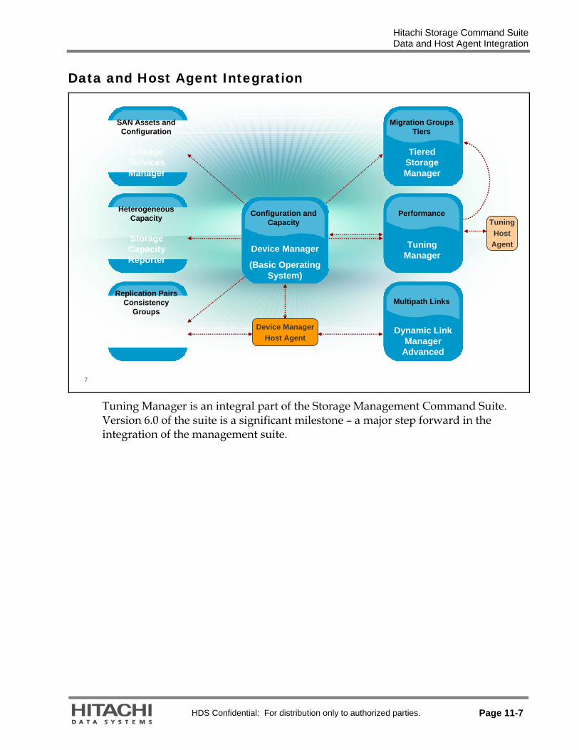
Hitachi Storage Command Suite Data and Host Agent Integration
HDS Confidential: For distribution only to authorized parties. Page 11-7
Data and Host Agent Integration
7
Device ManagerHost Agent
Replication Pairs Consistency
Groups
ReplicationManager
SAN Assets and Configuration
StorageServicesManager
HeterogeneousCapacity
StorageCapacityReporter
Multipath Links
Dynamic LinkManager
Advanced
Migration GroupsTiers
TieredStorageManager
Performance
TuningManager
Configuration andCapacity
Device Manager
(Basic Operating System)
TuningHost
Agent
Tuning Manager is an integral part of the Storage Management Command Suite. Version 6.0 of the suite is a significant milestone – a major step forward in the integration of the management suite.
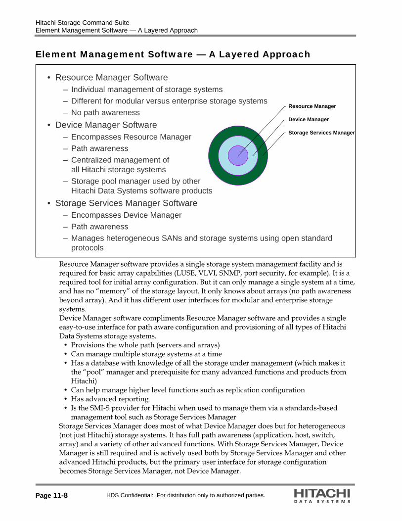
Hitachi Storage Command Suite Element Management Software — A Layered Approach
Page 11-8 HDS Confidential: For distribution only to authorized parties.
Element Management Software — A Layered Approach
• Resource Manager Software– Individual management of storage systems– Different for modular versus enterprise storage systems – No path awareness
• Device Manager Software– Encompasses Resource Manager– Path awareness– Centralized management of
all Hitachi storage systems– Storage pool manager used by other
Hitachi Data Systems software products• Storage Services Manager Software
– Encompasses Device Manager– Path awareness– Manages heterogeneous SANs and storage systems using open standard
protocols
Storage Services Manager
Device Manager
Resource Manager
Resource Manager software provides a single storage system management facility and is required for basic array capabilities (LUSE, VLVI, SNMP, port security, for example). It is a required tool for initial array configuration. But it can only manage a single system at a time, and has no “memory” of the storage layout. It only knows about arrays (no path awareness beyond array). And it has different user interfaces for modular and enterprise storage systems. Device Manager software compliments Resource Manager software and provides a single easy-to-use interface for path aware configuration and provisioning of all types of Hitachi Data Systems storage systems.
Provisions the whole path (servers and arrays) Can manage multiple storage systems at a time Has a database with knowledge of all the storage under management (which makes it
the “pool” manager and prerequisite for many advanced functions and products from Hitachi)
Can help manage higher level functions such as replication configuration Has advanced reporting Is the SMI-S provider for Hitachi when used to manage them via a standards-based
management tool such as Storage Services Manager Storage Services Manager does most of what Device Manager does but for heterogeneous (not just Hitachi) storage systems. It has full path awareness (application, host, switch, array) and a variety of other advanced functions. With Storage Services Manager, Device Manager is still required and is actively used both by Storage Services Manager and other advanced Hitachi products, but the primary user interface for storage configuration becomes Storage Services Manager, not Device Manager.

Hitachi Storage Command Suite Device Manager Software — Foundation for Higher Level Capabilities
HDS Confidential: For distribution only to authorized parties. Page 11-9
Device Manager Software — Foundation for Higher Level Capabilities
9
Business ApplicationModules
Storage OperationsModules
Basic Operating System
Hitachi Storage Specific HeterogeneousHeterogeneous
Device Manager
API – CIM/SMI-S Provisioning Configuration Replication Configuration
Resource ManagerVirtual Partition
ManagerServer Priority
Manager
QoS Application ModulesQoS Application ModulesOracle Oracle -- Exchange Exchange -- Sybase Sybase --SQL Server SQL Server –– NetAppNetApp OptionOption
QoS for QoS for File ServersFile Servers
SRMSRM
ChargebackChargeback PathPathProvisioningProvisioning Global Global
ReporterReporter
Storage Services Manager Storage Services Manager
Backup Backup Services Services ManagerManager
Tiered Storage Manager
Replication Monitor
Tuning Manager
Dynamic Link ManagerDynamic Link ManagerPath failover and failback load balancingPath failover and failback load balancing
Global Link ManagerGlobal Link Manager Protection Manager
Exchange - SQL Server
Reporting
Universal Volume Manager
Performance Monitor
This is a view of the Storage Management Command suite according to functional layer.
Light shaded modules support heterogeneous environments. Dark shaded modules support heterogeneous environments but are Sun storage system specific.
This is not a top-down dependency chart, although some top-down dependencies do appear within the chart. Rather, it is sorted into rows according to what the purpose and benefit of the product targets.
The first layer at the bottom is Enterprise storage system-specific modules for supporting and interfacing with Enterprise Systems arrays to get the most out of the storage system.
The second layer is made up of products that support storage systems on a operational basis – things that make efficient and reliable management of storage possible.
The top layer is modules that are application specific tools to improve application-to-storage service levels.

Hitachi Storage Command Suite Device Manager Software — Foundation for Higher Level Capabilities
Page 11-10 HDS Confidential: For distribution only to authorized parties.
The following products require and use Device Manager software in some way: Storage Services Manager software (and related add-on products) Replication Monitor software Tiered Storage Manager software Protection Manager software Other products include: Global Link Manager software Dynamic Link Manager software Tuning Manager software Backup Services Manager Resource Manager utility package Virtual Partitioning Manager software Universal Volume Manager software Performance Monitor feature Server Priority Manager software

Hitachi Storage Command Suite Device Manager Software and Resource Manager Software
HDS Confidential: For distribution only to authorized parties. Page 11-11
Device Manager Software and Resource Manager Software
10
ConfigurationConfigurationManagementManagement
PerformancePerformanceManagementManagement
BackupBackupManagementManagement
Device Manager software,Path Provisioning software,
Tiered Storage Manager software,
Replication Manager software
Device Manager software,Path Provisioning software,
Tiered Storage Manager software,
Replication Manager software
Storage Navigator program
Storage Navigator program
Storage Navigator program
Storage Navigator program
Tuning Manager software
Tuning Manager software
Protection Manager software,
Backup Services Manager software,
Data Protection Suite software
Protection Manager software,
Backup Services Manager software,
Data Protection Suite software
Daily Operations
Device Manager software and Storage Navigator program have many features that overlap. But Device Manager is predominantly used for daily storage administration tasks. Storage Navigator software functions are one-time operations, such as initial configuration of the storage system and maintenance. The deeper functionality provided by Storage Navigator program is not necessary for daily tasks. Preparation for Using Storage System (necessary only for the initial configuration):
Storage system installation Fibre Cable, network connection. IP Address definition MCU/RCM configuration for TrueCopy Remote Replication software Storage Pool definition for Copy-on-Write Snapshot volume
Configuration Management (daily storage administrator operations): Allocate new volume to the host Create volume pair Keep track with the current configuration Watch Error Alerts
Backup Management (may be included in the daily operations): Volume backup operations Configure pair volumes Perform pair operation in conjunction with application control (freeze and thaw DBMS, for example.)
Recover volume from the backup

Hitachi Storage Command Suite Device Manager Software— Solution to Complex Challenges
Page 11-12 HDS Confidential: For distribution only to authorized parties.
Device Manager Software— Solution to Complex Challenges
11
• Empowers existing resources to manage significantly more storage
• Enables and simplifies centralized management of dispersed storage
• Decreases repetitive human intervention by automating key elements of storage management procedures using CLI
• Reduces costly errors associated with manual storage management procedures
• Reports enterprise storage capacity chargebacks by logical group or line of business
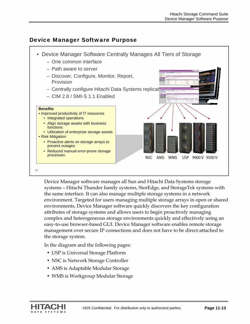
Hitachi Storage Command Suite Device Manager Software Purpose
HDS Confidential: For distribution only to authorized parties. Page 11-13
Device Manager Software Purpose
12
• Device Manager Software Centrally Manages All Tiers of Storage– One common interface – Path aware to server– Discover, Configure, Monitor, Report,
Provision – Centrally configure Hitachi Data Systems replication– CIM 2.8 / SMI-S 1.1 Enabled
Benefits• Improved productivity of IT resources
• Integrated operations• Align storage assets with business
functions• Utilization of enterprise storage assets
• Risk Mitigation• Proactive alerts on storage arrays to
prevent outages• Reduced manual error-prone storage
processes
Device Manager software manages all Sun and Hitachi Data Systems storage systems – Hitachi Thunder family systems, StorEdge, and StorageTek systems with the same interface. It can also manage multiple storage systems in a network environment. Targeted for users managing multiple storage arrays in open or shared environments, Device Manager software quickly discovers the key configuration attributes of storage systems and allows users to begin proactively managing complex and heterogeneous storage environments quickly and effectively using an easy-to-use browser-based GUI. Device Manager software enables remote storage management over secure IP connections and does not have to be direct-attached to the storage system.
In the diagram and the following pages: USP is Universal Storage Platform NSC is Network Storage Controller AMS is Adaptable Modular Storage WMS is Workgroup Modular Storage

Hitachi Storage Command Suite Device Manager Business Agility
Page 11-14 HDS Confidential: For distribution only to authorized parties.
Device Manager Business Agility
13
FinanceSanta Clara• Organizes and manages
storage from a logical perspective, along lines of business, departments, criticality or storage class
• Immediate view of available storage and current usage
• Consolidated control of Hitachi storage as well as externally-attached Sun Enterprise Storage Systems
• Enables easy deployment of storage resources to meet business and application needs
Lightning 9900V
Thunder 9500V
Thunder 9500 SATA
Backup ArchiveGeneralPurpose100%99.99%High Perf.
OracleEmail
FC/IPSAN
Device Manager
Physical Storage Pool
In the page:
Thunder 9500V is Hitachi Thunder 9500™ V Series modular storage Thunder 9500 SATA is SATA Intermix Option for Hitachi Thunder 9500™ V Series modular storage systems
Lightning 9900 V is Hitachi Lightning 9900™ V Series enterprise storage

Hitachi Storage Command Suite Device Manager Capabilities
HDS Confidential: For distribution only to authorized parties. Page 11-15
Device Manager Capabilities
14
The Logical device configuration information of the discovered storage systems is placed into a part of the database referred to as the “logical” section called ‘All Storage’. The information is split into four categories for each enterprise system. 1. Open - Allocated – Open volumes that are already assigned paths to a host (mapped) 2. Open - Unallocated - Open volumes that have not been assigned paths to a host 3. Open - Reserved - Volumes that cannot be assigned paths such as Dynamic Provision
pool volume, Copy-on-Write Snapshot data pool volume, Universal Replicator journal volume, DM-LU volume containing the differential information during a copy operation, On-demand volume and Reserve volume used in Volume Migration (Universal Storage Platform V and Universal Storage Platform), Lightning 9900 V Series enterprise storage systems, or Lightning 9900 Series enterprise storage systems.
4. Mainframe - Unspecified - Refers to logical devices installed and defined as mainframe volumes and only applies to enterprise systems.
5. Pools – Reserved volumes defined as pool volumes 6. External Storage - Virtualized volumes physically located in External Storage The detail display of “Open - Allocated” provides configuration and map information about ALL open volumes from the selected storage system. Note that a link to a host will only be available if the host name and the WWN of it is already known to Device Manager at the time the Add Storage command is issued.

Hitachi Storage Command Suite Link and Launch Operations
Page 11-16 HDS Confidential: For distribution only to authorized parties.
Link and Launch Operations
15
• The following applications can be linked and launched using the Device Manager software GUI:
– Tuning Manager software– Dynamic Link Manager software– Protection Manager software– Provisioning Assistant software (in Device Manager software bundle)– Storage Navigator Modular program (for Web)– Disk Array Management Program (for Web)– Storage Services Manager software– Replication Monitor software– Global Link Manager software– NAS Manager Suite of software – Tiered Storage Manager software

Hitachi Storage Command Suite Device Manager Configuration Operations
HDS Confidential: For distribution only to authorized parties. Page 11-17
Device Manager Configuration Operations
16
• Device Manager supports the following system and volume configuration functions:
– Configure Ports – Create/Delete Array Groups – Create/Delete LDEVs – Configure Spare Drives – LUN Expansion (LUSE)– Add/Delete Volume Path
• LUN Security: – Secure/Unsecured Volumes
• Data Replication/Backup (Copy) Operations: – Set/Cancel Command Device – Configures TrueCopy software replication pairs– Configures ShadowImage software replication pairs– Configures Copy-On-Write Snapshot software

Hitachi Storage Command Suite Device Manager Components
Page 11-18 HDS Confidential: For distribution only to authorized parties.
Device Manager Components
17
• Device Manager software consists of the following components:– Server and its subcomponent (on the management server)– Host agent (on the customer production server)– Management console (using a web browser)
Device Manager ServerSAN
Agent
ManagementServer
ManagementServer
Production Server (Host)Production Server (Host)
ManagementConsole (Client)
ManagementConsole (Client)
Storage SystemsStorage Systems
Management LAN
HBase
AIX WindowsHP-UX
AgentAgent

Hitachi Storage Command Suite Provisioning Manager
HDS Confidential: For distribution only to authorized parties. Page 11-19
Provisioning Manager
18
• Device Manager’s Provisioning Manager functionalities are:– Storage Pool Management – Host Volume Management
Allocate LDEVs to a Host (*)
Select the optimal LDEVs from Storage Pool
AllocateStorage
CreateFile System Create Device File
Create File System
Mount to File System
StoragePool
Host
Subsystem
Storage
(*) Launch HDvM
Provisioning Manager component of Device Manager bundle provides the functionality to integrate and manage various models and types of storage systems as a single, logical storage pool. In Provisioning Manager, a storage pool refers to a managed data storage area that resides on a set of storage systems. A storage pool is a collection of volumes (LUs). You can use Device Manager's All Storage (My Storage) functionality to place the storage pools into hierarchies and manage a storage pool for each user group.

Hitachi Storage Command Suite Provisioning Manager
Page 11-20 HDS Confidential: For distribution only to authorized parties.
19
• Uniform provisioning interface for the following operating systems– Microsoft® Windows®
– UNIX (AIX, HP-UX, Sun Solaris)– Linux (Red Hat, SUSE)
• Supports the following volume operations on the host:– Add file system– Expand file system– Delete file system– Add device file– Delete device file

Hitachi Storage Command Suite Provisioning Manager Host Volume Management
HDS Confidential: For distribution only to authorized parties. Page 11-21
Provisioning Manager Host Volume Management
20
• The Host Volume Configuration wizard provides a consistent and simple interface for volume management
Windows
HDvM Agent
diskpart
Execute
Solaris
HDvM Agent
VxVM
Execute
AIX
HDvM Agent
LVM
Execute
HPvM
AddFileSystem
GetFileSystem
“list volume”
“vxmake”
“mklv”
ExpandFileSystem
Creating a file system on a volume (LU) allocated to a host, expanding a file system, and deleting a file system can all be performed from a management client in single operations.
In the diagram: HDvM stands for Hitachi Device Manager software HPvM stands for Hitachi Provisioning Manager software

Hitachi Storage Command Suite Preparation to Start Software Operations
Page 11-22 HDS Confidential: For distribution only to authorized parties.
Preparation to Start Software Operations
21
• Verify that the Device Manager server has been installed successfully• Web clients should have Java Runtime Environment (JRE) and Java Web
Start (JWS) installed• Launch the web browser and enter
the URL for the Device Manager server
• Register the license key of the storage system you want to manage in Device Manager
• Default User name is system and default Password is manager
http://<Device-Manager-server-address>:<port-number>/DeviceManager/

Hitachi Storage Command Suite Add Storage Systems
HDS Confidential: For distribution only to authorized parties. Page 11-23
Add Storage Systems
22
• Add Subsystems to Device Manager
Add Subsystem is the function that will connect to the specified storage system, reading the current configuration information into the Device Manager Server repository.
Caution: The Device Manager software server requires exclusive access to a storage system. Ensure that a single storage system is managed by only one Device Manager software server. One storage system should not be managed by Device Manager software and another management tool (for example, Storage Navigator program or the Service Processor’s (SVP) Resource Manager utility package) at the same time. For all Hitachi/Sun enterprise storage systems, the SVP must be in View mode.

Hitachi Storage Command Suite Add Storage Systems
Page 11-24 HDS Confidential: For distribution only to authorized parties.
23
• Subsystem View
As a result of the Add Subsystem function, the base configuration information of the discovered storage systems is put into the Device Managers repository Physical View section listed as Subsystems in the Navigation frame.
The Last Refreshed time will be displayed in the Subsystem List screen, All Storage screen and the Subsystem Property screen. This time is updated when a subsystem is added or refreshed.

Hitachi Storage Command Suite Add Storage Systems
HDS Confidential: For distribution only to authorized parties. Page 11-25
24
• Host Configuration View
The third part of the Device Manager repository is referred to as Hosts section.
An Add Subsystem command will not place “Application Host” information into HiRDB.
The Host information was obtained from the Device Manager Agent running on that Application Server.
The above also indicates the case where External Storage Ports are configured on the Universal Storage Platform. These are indicated as EXSP Hosts.

Hitachi Storage Command Suite Add Host
Page 11-26 HDS Confidential: For distribution only to authorized parties.
Add Host
25
• Adding a Host Manually
Hosts to be managed by Device Manager must be added manually if they do not have the Device Manager Agent installed.
To manually add the required host information, click Add Host and enter the host name in the Name field section, and then click Add in the World Wide Name field section to provide the correct WWN information.
Caution: It is recommended that you add all hosts before performing a LUN scan operation. If you do not enter the hosts before performing a LUN scan, the LUN scan will automatically create a unique host name (host_0, host_1and others) for each WWN found securing any LUN. This can create a significant number of hosts depending on the size of the environment.

Hitachi Storage Command Suite Add Host
HDS Confidential: For distribution only to authorized parties. Page 11-27
26
• Result of Adding a Host Manually

Hitachi Storage Command Suite LUN Scan Operation
Page 11-28 HDS Confidential: For distribution only to authorized parties.
LUN Scan Operation
27
• Only users with the Modify permission can perform a LUN Scan operation.• After a new storage system is detected, none of the LUNs defined in the
storage system are associated with a (user-defined) storage group.– When you perform a LUN Scan operation after adding a storage system and
its associated hosts, Device Manager software creates a hierarchy of logical groups and storage groups to contain all of the existing LUNs in the storage system.
• The LUN Scan operation creates the LUN Scan group immediately under the Logical Groups object.
– Logical groups for each storage system are created within the LUN Scan group, and LUNs are placed in storage groups organized by ports and security.
• The LUNs in the LUN SCAN group can be moved to new or existing storage groups as desired.
• The LUN Scan operation also causes Device Manager software to register the hosts that have WWNs associated with the LUNs.

Hitachi Storage Command Suite LUN Scan
HDS Confidential: For distribution only to authorized parties. Page 11-29
LUN Scan
28
• LUN Scan Operation
With a LUN Scan operation, Device Manager will create a hierarchical structure of Logical Groups and Storage Groups to reflect the existing LUN configuration of the Host Storage Domains in the storage system selected. The LUN Scan operation creates a new Logical Structure in My Groups:
Logical groups for each storage system are created within the LUN SCAN group, and LUNs are placed in storage groups organized by ports and security.
The LUNs in the LUN Scan group can be moved to new or existing storage groups as desired.
The LUN Scan also causes Device Manager to register the hosts that have WWNs associated with the LUNs. The properties of the host registered by Device Manager are updated when the Device Manager agent sends information about the host.
Important: A LUN scan operation will automatically create a unique host name (host_0, host_1, and others) for each WWN found in existing Host Storage Domains of the subsystem, if there is no matching WWN found in any of the hosts already registered in Device Manager. This can create a significant number of hosts, depending on the size of the environment.

Hitachi Storage Command Suite LUN Scan
Page 11-30 HDS Confidential: For distribution only to authorized parties.
29
• Logical Structure as a Result of LUN Scan

Hitachi Storage Command Suite LUN Scan
HDS Confidential: For distribution only to authorized parties. Page 11-31
30
• Result of a LUN Scan - Host View
As a result of the LUN Scan operation, additional hosts with the names host_0 through host_4 have been generated.
LUN Scan found five WWN existing in the subsystems configuration but no matching entry in the Host section of Device Manager. Since the purpose of WWN security is to assure that a secured volume can be access only by a specific host, Device Manager has created one host for each WWN in the subsystem with no match in the Host section of Device Manager. This indicates that multipath access to a host is not be considered.
With the Host Modify Properties option, host names as well as WWN relationship can be altered.

Hitachi Storage Command Suite Storage Management
Page 11-32 HDS Confidential: For distribution only to authorized parties.
Storage Management
31
• Logical Group– May contain subordinate logical groups and/or storage groups containing
LUNs– Storage cannot be added directly to logical groups– Logical groups are displayed under the Logical Groups object
• Storage Group – A logical group for which paths to storage have been set– A collection of any user-specified LUNs (access paths)– Storage groups are placed under logical groups
• Logical groups cannot be placed under storage groups• User Group
– Users in a user group can only see and manage the logical groups, hosts and volumes that are assigned to that user group
– User groups are displayed in the User Group Administration window (restricted to administrators)

Hitachi Storage Command Suite My Groups
HDS Confidential: For distribution only to authorized parties. Page 11-33
My Groups
32
• Create Logical Groups
The default logical structure All Storage is built by Device Manager’s Add Subsystem function.
The users can create their own logical structure in My groups > Logical Groups reflecting names and subdivisions of storage meaningful to their administration. Creation of different users allows for log-in authorization on different levels.

Hitachi Storage Command Suite My Groups
Page 11-34 HDS Confidential: For distribution only to authorized parties.
33
• Nesting Logical Groups
The new Logical Group Database Storage is called nested since it has the Logical Group HDS Academy as parent group. The Group DB-Stor is nested into HDS Academy/Database Storage and will become the Storage Group.

Hitachi Storage Command Suite My Groups
HDS Confidential: For distribution only to authorized parties. Page 11-35
34
• Create Storage Groups
Definition of Logical Group and Storage Group
A Logical group is parent to other logical groups or storage groups and cannot contain storage itself. Storage group cannot be parent to other groups. It can be nested within a logical group. It can also be empty but usually will contain the storage to be managed. Adding storage to a newly created group would make it to be considered Storage Group. The Add Storage function is available to perform this operation.

Hitachi Storage Command Suite My Groups
Page 11-36 HDS Confidential: For distribution only to authorized parties.
35
• Add Storage
Storage Group
Operation available for a Storage Group containing storage already are: Add Like Storage, Add Storage, Remove Storage, Move Storage, and Modify Security
For the existing Storage an Edit Label function is available

Hitachi Storage Command Suite User Account Management
HDS Confidential: For distribution only to authorized parties. Page 11-37
User Account Management
36
• Create User
Device Manager Users logged in with administration permissions can create new user accounts and set user permissions.
User accounts common to other Storage Management Command Suite products can be managed from Device Manager software.

Hitachi Storage Command Suite User Account Management
Page 11-38 HDS Confidential: For distribution only to authorized parties.
37
• Assign Permissions
Permissions related to Device Manager software users include permissions for performing Device Manager software operations as well as permission for managing user accounts common to other Storage Management Command Suite products.
Note: To prevent unauthorized access, change the default system administrator login, or add at least one system administrator and then delete the default system administrator.

Hitachi Storage Command Suite Sample LUN Security
HDS Confidential: For distribution only to authorized parties. Page 11-39
Sample LUN Security
38
• LUN security is implemented by appropriate host storage domain configuration.
PORT 1-A PORT 1-B PORT 2-A PORT 2-B
HOST1 (WWN1)
Storage System Port (Storage Provider)
LUN
Sec
uri
ty T
arge
t (S
tora
ge C
onsu
mer
)
HOST2 (WWN2)
HOST3 (WWN3)
HOST4 (WWN4)
HOST5 (WWN5)
HOST6 (WWN6)
HSD1
HSD2 HSD3
HSD4
HSD 5
These LUNs are available for HOST1, 2, 3 and 4. They need to be accessed using Port 1-A.
These LUNs are available for all hosts.

Hitachi Storage Command Suite Configuring LUN Security (Add Storage Wizard)
Page 11-40 HDS Confidential: For distribution only to authorized parties.
Configuring LUN Security (Add Storage Wizard)
39
• The graphical user interface (GUI) for Device Manager software provides an Add Storage Wizard for storage administrators to ease complexity of host storage domain usage.
• The Wizard detects the necessity for new host storage domain creation when a storage administrator tries to configure a new LUN security.
– When no new host storage domain is required, Device Manager software reuses an already-defined host storage domain for the new LUN configuration.
• Device Manager software also tells the storage administrator which ports on the storage system are still available for LUN security configuration.

Hitachi Storage Command Suite Device Manager Reporting
HDS Confidential: For distribution only to authorized parties. Page 11-41
Device Manager Reporting
40
• Built-in reporting function to generate reports in HTML format and comma-separated value (CSV) format. Reports include:
– Physical Configuration of Storage System – Physical configuration of the storage systems being managed
– Storage Utilization by Host – Storage utilization organized and presented by host
– Storage Utilization by Logical Group – Storage utilization organized and presented by logical group
– Users and Permissions – Device Manager users and permissions

Hitachi Storage Command Suite Command Line Interface (CLI)
Page 11-42 HDS Confidential: For distribution only to authorized parties.
Command Line Interface (CLI)
41
The CLI version of the Device Manager software is available for users who prefer to use a character-based interface to create their own automation scripts.
Server Host
Solaris CLIClient
Windows CLIClient
Communicated by XML/API on HTTP (or HTTPS) protocol

Hitachi Storage Command Suite Tuning Manager Software
HDS Confidential: For distribution only to authorized parties. Page 11-43
Tuning Manager Software
42
Business ApplicationModules
Storage OperationsModules
Basic Operating System
Hitachi Storage Specific HeterogeneousHeterogeneous
Device Manager
API – CIM/SMI-S Provisioning Configuration Replication Configuration
Resource ManagerVirtual Partition
ManagerServer Priority
Manager
QoS Application ModulesQoS Application ModulesOracle Oracle -- Exchange Exchange -- Sybase Sybase --SQL Server SQL Server –– NetAppNetApp OptionOption
QoS for QoS for File ServersFile Servers
SRMSRM
ChargebackChargeback PathPathProvisioningProvisioning Global Global
ReporterReporter
Storage Services Manager Storage Services Manager
Backup Backup Services Services ManagerManager
Tiered Storage Manager
Replication Monitor
Tuning Manager
Dynamic Link ManagerDynamic Link ManagerPath failover and failback load balancingPath failover and failback load balancing
Global Link ManagerGlobal Link Manager Protection Manager
Exchange - SQL Server
Reporting
Universal Volume Manager
Performance Monitor

Hitachi Storage Command Suite The Performance Management Challenge without Tuning Manager Software
Page 11-44 HDS Confidential: For distribution only to authorized parties.
The Performance Management Challenge without Tuning Manager Software
43
• The performance and capacity management challenge of a SAN storage environment
StorageServer SAN
Serverreport
Switchreport
Server tool Switch tool Storage tool
Gather Data
Storagereport
Device-specific tools
Correlate the data
Spreadsheet
• Interpret each report separately• Integrate the Data Manually
– Synchronize time stamps– Unify different data formats– Correlate various reports
App
Troubleshooting requires a view of the path from the application to the storage system. Without a tool that consolidates and normalizes all of the data, the system administrator has difficulty distinguishing between the possible sources of problems in the different layers involved. When a performance problem occurs or the “DB application response time exceeds acceptable levels”, they must quickly determine if the problem is in the application server or outside.
Server/Application Analysis � Is the problem caused by trouble on the server? (DB, file system, HBA)
Fabric Analysis � Is there a SAN switch problem? (Port, ISL, and more)
Storage Analysis � Is the storage system a bottleneck?
All of the data from the components of the Storage network must be gathered by different device-specific tools and interpreted, correlated and integrated manually, including the timestamps, in order to find the root cause of a problem.
Some customers achieve this by exporting lots of data to spreadsheets, and then manually sorting and manipulating the data.
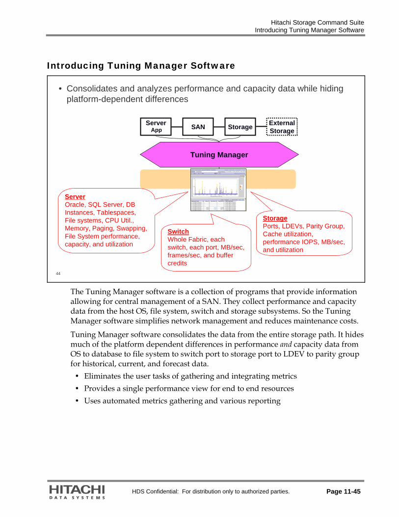
Hitachi Storage Command Suite Introducing Tuning Manager Software
HDS Confidential: For distribution only to authorized parties. Page 11-45
Introducing Tuning Manager Software
44
StorageServer SAN
Tuning Manager
StoragePorts, LDEVs, Parity Group, Cache utilization, performance IOPS, MB/sec, and utilization
App
• Consolidates and analyzes performance and capacity data while hiding platform-dependent differences
ServerOracle, SQL Server, DB Instances, Tablespaces, File systems, CPU Util., Memory, Paging, Swapping, File System performance, capacity, and utilization
SwitchWhole Fabric, each switch, each port, MB/sec, frames/sec, and buffer credits
ExternalStorage
The Tuning Manager software is a collection of programs that provide information allowing for central management of a SAN. They collect performance and capacity data from the host OS, file system, switch and storage subsystems. So the Tuning Manager software simplifies network management and reduces maintenance costs.
Tuning Manager software consolidates the data from the entire storage path. It hides much of the platform dependent differences in performance and capacity data from OS to database to file system to switch port to storage port to LDEV to parity group for historical, current, and forecast data.
Eliminates the user tasks of gathering and integrating metrics Provides a single performance view for end to end resources Uses automated metrics gathering and various reporting

Hitachi Storage Command Suite Centralized Performance and Capacity Management
Page 11-46 HDS Confidential: For distribution only to authorized parties.
Centralized Performance and Capacity Management
45
• Proactive Storage Resource Management Requires:– A thorough understanding of all components of your current environment and
their baseline or normal behavior– The ability to view all SAN-attached servers, databases, file systems,
switches, storage systems, logical volumes, disk array groups, and their relationships to each other
– A historical database for analyzing trends that may signal potential problems in applications or storage
– The ability to view the performance of a resource at a specific past point-in-time, so that you can correlate any recent configuration changes with changes in application performance or response time

Hitachi Storage Command Suite Types of Data Collected by Tuning Manager
HDS Confidential: For distribution only to authorized parties. Page 11-47
Types of Data Collected by Tuning Manager
46
• Storage Systems: – Performance IOPS (Read. Write,
Total), MB/sec transferred/sec, history, forecast, real-time monitor
– By All Storage systems– By A Single storage system– By Port – By LDEV– Cache utilization– By Disk Parity Group– By Database Instance, tablespace,
Index and more
• SAN Switches: – Bytes Transmitted/Received,
Frames Transmitted/Received by SAN, by switch, by port
– CRC Errors, Link Errors, Buffer Full/Input Buffer Full, and more
• Servers:– Server capacity/utilization/performance– I/O Perform - total MB/sec, Queue lengths,
read/write IOPS, I/O wait time– File system – Space allocated, used, available,– Reads/Writes, Queue lengths– Device File – Performance and capacity– CPU busy/wait, Paging/Swapping, process
metrics, IPC Shared memory, semaphores, locks, threads and more
– NFS client detail, NFS Server Detail– HBA bytes transmitted/received
• Applications:– Oracle Table Space Performance and capacity
Buffer pools, cache, data blocks read/write, Tablespaces used, free, and Logs
– Microsoft SQL Server Cache Usage: current cache hit %/trends, Page Writes/sec, Lazy Writes /sec., Redo Log I/O/ sec, and Network: packets sent/received
– DB2 Table Space Performance and capacity Buffer pools, cache, data blocks read/write, Tablespaces used, free, and logs
– Exchange database, shared memory queue, information store, mailbox store, public store, and Exchange server processes
Tuning Manager reports on and analyzes current, historical, and forecast data.

Hitachi Storage Command Suite Resources That Can Be Monitored
Page 11-48 HDS Confidential: For distribution only to authorized parties.
Resources That Can Be Monitored
47
• Agents Run On– HP-UX V1, V2 (PA-RISC), V3 (IPF), 11i V3 (IPF)– Windows 2000 x86 SP3 & SP4– Windows 2003 Server (IA-32/IA-64) no-SP, SP1 & SP2– Windows 2003 Server x64– Windows 2003 R2 Server Std, Enterprise and x64– Red Hat Enterprise Linux ES 4, 4.5, 5, 5.1 and Linux AS 4– Solaris 9, Solaris 10– AIX 5L V5.2, V5.3, HACMP 5.2, HACMP 5.3, Supporting
Dynamic Tracking
• DB Applications– Oracle (9.0.1, 9.2.0, 10.1.0, 10gR2), RAC
• Now on Red Hat Linux 4.5, 5, 5.1– Microsoft SQL Server 2000 Enterprise & Standard– Microsoft SQL Server 2005 Enterprise & Standard
• Now on x64– Microsoft Exchange 2003 and 2007 Servers– IBM DB2 (8.1, 8.2)
• Now on Red Hat Linux 4.5, 5, 5.1
• Volume Managers– Veritas VxVM (Windows, Solaris, HP-UX, AIX)
• VxVM 4.1 on Solaris– AIX LVM– HP-UX LVM– Red Hat Enterprise Linux 4, 4.5, 5, 5.1 LVM2– Sun SVM for Solaris 9 and 10
• Storage Systems– Universal Storage Platform, Universal Storage Platform V
and VM, Network Storage Controller, model NSC55– Lightning 9900V, 9900 Series– Workgroup Modular Storage100, Adaptable Modular Storage
200/500/1000• iSCSI on Workgroup Modular Storage or Adaptable
Modular Storage – Thunder 9500V, 9500, 9200 Series systems– NAS Manager for Universal Storage Platform, Network
Storage Controller model NSC55– NAS Manager for Lightning 9900V Series– NAS Manager for Adaptable Modular Storage 1000/500/200
• Switches– Brocade SilkWorm 200E, 2000 Series, 3014, 3200/3800,
3250/3850, 3900, 4100, 12000, 24000, 48000, 4900, 5000 (on Windows)
• Firmware updates– McDATA Sphereon 3016/3032/3216/3232, 4500– McDATA Intrepid 6064/6140, i10k– McDATA EFCM 9.01.00, 09.01.01, 09.02, 09.06.00, 09.06.01– Cisco 9120, 9140, 9216i (Windows management server only)– Cisco 9506, 9509, 9513 (on Windows)
• Firmware updates• Tuning Manager Server Software Runs On
– Microsoft Windows 2000 SP3, SP4– Microsoft Windows 2003, R2 no-SP, SP1 & SP2– Sun Solaris 9, and 10
• Multi-path Software– Dynamic Link Manager software– Veritas DMP– AIX 5L native (MPIO)– HP-UX 11i V3 (IPF) native (MPIO) No longer supported:
• Oracle 9i R1
Those recently added are shown in red.
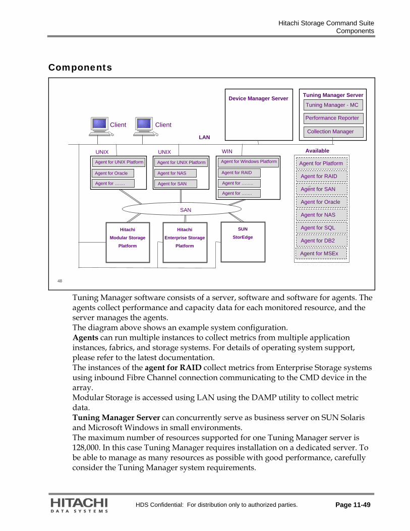
Hitachi Storage Command Suite Components
HDS Confidential: For distribution only to authorized parties. Page 11-49
Components
48
SAN
LAN
Available
Agent for Platform
Client
Hitachi
Modular Storage
Platform
Hitachi
Enterprise Storage
Platform
Client
Agent for RAID
Agent for SAN
Agent for Oracle
Agent for NAS
Agent for SQL
Agent for DB2
Tuning Manager Server
Tuning Manager - MC
Performance Reporter
Collection Manager
WIN
Agent for RAID
Agent for Windows Platform
Agent for MSEx
UNIX
Agent for UNIX Platform
UNIX
Agent for UNIX Platform
Agent for Oracle Agent for NAS
Agent for ……..
Agent for …….
Agent for ……. Agent for SAN
SUN
StorEdge
Device Manager Server
Tuning Manager software consists of a server, software and software for agents. The agents collect performance and capacity data for each monitored resource, and the server manages the agents. The diagram above shows an example system configuration. Agents can run multiple instances to collect metrics from multiple application instances, fabrics, and storage systems. For details of operating system support, please refer to the latest documentation. The instances of the agent for RAID collect metrics from Enterprise Storage systems using inbound Fibre Channel connection communicating to the CMD device in the array. Modular Storage is accessed using LAN using the DAMP utility to collect metric data. Tuning Manager Server can concurrently serve as business server on SUN Solaris and Microsoft Windows in small environments. The maximum number of resources supported for one Tuning Manager server is 128,000. In this case Tuning Manager requires installation on a dedicated server. To be able to manage as many resources as possible with good performance, carefully consider the Tuning Manager system requirements.

Hitachi Storage Command Suite Components
Page 11-50 HDS Confidential: For distribution only to authorized parties.
49
• Summary of Tuning Manager Server Components
Common Component provides general-use functions used by all Storage Command Suite products.
Common Component
Collection Manager manages agent services distributed over the network and controls the alarm events issued by agents.
Collection Manager (CLM)
Performance Reporter collects data such as performance data and capacity information from the Store database of agents and creates reports.
Performance Reporter (PR)
Main Console is used to generate reports from the configuration, performance, and capacity information collected in the system.
Main Console (MC)
DescriptionComponent Name
Main Console
The performance and capacity information about an entire SAN environment can be viewed as historical data. The following information is associated and then displayed:
Performance and capacity information about the file systems on the application server and application programs
Performance and information, regarding the ports of the storage subsystems and devices that store the above information
Performance Reporter
It displays detailed information about the performance and capacity of items, such as file systems on the application server, application programs, or storage subsystems in real time or recent past.
Collection Manager
It retrieves metric data from the agents on a scheduled base, by manual order or on order of the Performance Reporter.

Hitachi Storage Command Suite Agents
HDS Confidential: For distribution only to authorized parties. Page 11-51
Agents
50
Agent for Microsoft Exchange Server collects information such asperformance data for Microsoft Exchange Server.
Agent for Microsoft Exchange Server (for Windows systems only)
Agent for Platform collects information such as data on OS activities and server performance.
Agent for Platform (Windows®, UNIX)
Agent for RAID Map, maps servers to storage subsystems and collects information, such as configuration information of host file systems and the associated storage subsystems. A system managed by a Tuning Manager server requires at least one instance of agent for RAID Map.
Agent for RAID Map
Agent for RAID Map, agent for Platform, and agent for Microsoft Exchange Server are included in agent for Server System.
Agent for Server System
Agent for RAID collects information such as performance data forstorage subsystems.
Agent for RAID
DescriptionAgent Name
Agent for SAN Switch collects information such as switch performance data.
Agent for SAN Switch
Agent for NAS collects information such as performance data and capacity information for the NAS system.
Agent for NAS
Agent for Oracle collects information such as Oracle database performance data.
Agent for Oracle
Agent for Microsoft SQL Server collects information such as Microsoft SQL Server database performance data.
Agent for Microsoft SQL Server
DescriptionAgent Name

Hitachi Storage Command Suite Positioning
Page 11-52 HDS Confidential: For distribution only to authorized parties.
Positioning
52
• Product Positioning In Context to Performance
A tool for migrating data between heterogeneous storage devices, simplifying the identification, classification, and movement of volumes.
Tiered Storage Manager
A tools package for active tuning of Sun Enterprise Storage Systems – changing configuration to enhance performance.
Performance Maximizer Suite
Hitachi Data Systems’ heterogeneous SAN management framework which includes path performance monitoring and capacity planning.
Storage Services Manager
The advanced reporting, analysis and troubleshooting application for Hitachi storage systems and services, leveraging storage path awareness and deep knowledge of Sun Enterprise Storage Systems.
Tuning ManagerDescriptionName
• Performance Maximizer Suite Complements Tuning Manager Software– Together they provide the customer a comprehensive performance and
capacity management solution.– Volume Migration (formerly CruiseControl) and Server Priority Manager
(Priority Access) provide “active tuning” and load balancing. – Performance Monitor (Hitachi Enterprise Storage Systems), provides deep
storage diagnostic information, but has no knowledge of the storage path, the database, SAN switch, or file system, and no capacity information or historical database.

Hitachi Storage Command Suite High-level Architecture
HDS Confidential: For distribution only to authorized parties. Page 11-53
High-level Architecture
54
Server DBServer DB
Configuration(Latest only)
Capacity(Historical)
Performance(Historical)
Device ManagerDevice Manager
Configuration(Latest)
Capacity
Tuning Manager ServerTuning Manager Server
Capacity(Historical)
Configuration(Historical)
Main ConsoleVersion 5.x
Main Console 6.0
Agent DBsAgent DBs
Configuration
Capacity
Performance(Historical)
Agentsfor RAIDAgents
for RAID
Configuration
Performance(Historical)
Agents (except RAID)
Agents (except RAID)
Configuration
Capacity
Performance(Historical)
Hourly Summary
Tuning Manager 6.0 includes a major redesign of the architecture. In version 5.x, each individual agent (storage systems, switches, servers and applications) has a database containing performance, capacity and configuration information. That data is polled and collected into a master Tuning Manager server database.
As you may recall or be aware, starting with version 6, these agent databases could be virtually unlimited in size, allowing for retention of details (minute-level) data for much longer periods of time.

Hitachi Storage Command Suite High-level Architecture
Page 11-54 HDS Confidential: For distribution only to authorized parties.
55
Array monitoring
HTM-Agents (except RAID)HTM-Agents
(except RAID)
Configuration
Capacity
Performance(Historical)
HTM-AgentsHTM-Agents
Configuration
Capacity
Performance(Historical)
HTM-Server DBHTM-Server DB
Configuration(Latest only)
Capacity(Historical)
Performance(Historical)
HDvM DBHDvM DB
Configuration(Latest)
Capacity
HTM-Server DBHTM-Server DB
Capacity(Historical)
Configuration(Historical)
Server DB no longer has performance data. MC displays
performance reports directly from each agent store instead.(*)
So minute level data from agent store is now available in MC.
Historical configuration data is now being
collected to show more accurate SAN resource
correlations in historical reports.
New Report Framework and
DB access engine
HTM MC 5.x
HTM-Agentfor RAID
HTM-Agentfor RAID
Configuration
Performance(Historical)
RAID agent collects configuration data for its
own sake, but it is not stored into HTM-Server DB.
HTM MC 6.0
In the diagram and the following pages:
HTM is Tuning Manager software HDvM is Device Manager software

Hitachi Storage Command Suite Data Collection Basics for Monitoring Arrays
HDS Confidential: For distribution only to authorized parties. Page 11-55
Data Collection Basics for Monitoring Arrays
56
• HTM-Server gets array configuration from HDvM. HiRDB now keeps config and capacity only• HTM MC retrieves performance data from agents based on configuration in HiRDB
Agent Storeservice
Agent instance
CollectionManager
HiRDB
HTMMain Console
V6.0 On-demandreport
MinutelyHourlyDaily
Weekly
Monthly
Yearly
AgentCollector
PD
Device Manager
PI
Capacity
Configuration
USP #1
USP #2
USP V #3
USP VM #4
USP VM #5
AMS #1
AMS #2
Monitored by RAID Agent
Monitored by HDvM
HTM-Server monitors these subsystems only
Capacity
Configuration
performance
capacity &configuration
Data collection at 1am everyday
by defaultHiRDB keeps historical configuration and capacity data w/o performance data.
HDvMData
Collection
Tuning Manager -Server
Device Manager provides consistent, easy to use, and easy to configure interfaces for managing storage products. In addition to a command line interface (CLI) for scripting, Device Manager provides a Web-based GUI for managing storage products. Device Manager also provides maintenance commands for backing up and recovering the database that stores configuration information. The Tuning Manager server uses the internal components of the Main Console and Collection Manager to collect data from Device Manager and Agents. You can display the collected data by using the Main Console and Performance Reporter. The Main Console stores the configuration and capacity information that the Agents and Device Manager collect from the monitored resources in the database. In the diagram: PI = Product Interval PD = Product Detail HiRDB = Hitachi Relational Database SMS100 = Simple Modular Storage model 100 WMS100 = Hitachi Workgroup Modular Storage system model 100 AMS200 = Hitachi Adaptable Modular Storage system model 200 AMS500 = Hitachi Adaptable Modular Storage system model 500 AMS1000 = Hitachi Adaptable Modular Storage system model 1000 USP VM = Hitachi Universal Storage Platform™ VM USP V = Hitachi Universal Storage Platform™ V

Hitachi Storage Command Suite Data Collection Basics for Monitoring Hosts, Switches, and Databases
Page 11-56 HDS Confidential: For distribution only to authorized parties.
Data Collection Basics for Monitoring Hosts, Switches, and Databases
57
Agent Storeservice
Agent instance
CollectionManager
HiRDB
HTMMain Console
V6.0 On-demandreport
MinutelyHourly
Daily
Weekly
Monthly
Yearly
AgentCollector
HiRDB keeps historical configuration and capacity data w/o performance data.
PD
PI
Switch #2
Oracle DB #3
SQL Server #4
DB2 #5
Monitored by each agent
Capacity
Configuration
performance
Capacity &configuration
Server #1
Data collection at midnight everyday
by default
• HTM-Server gets configuration from each agent. HiRDB now keeps config and capacity only• HTM MC retrieves performance data from agents based on configuration in HiRDB
Tuning Manager -Server
Agents run in the background and collect and record performance data. A separate agent must exist for each monitored resource.
The agents can continually gather hundreds of performance metrics and store them in the Store databases for instant recall. Agents enable the Tuning Manager server to collect the performance data of monitored objects. The collected data is used to display information about the entire SAN environment in the Main Console and information about specific resources in Performance Reporter. An agent collects the performance data from a monitored OS, database (such as Oracle), or storage subsystem, and then stores the performance data in its database. Such databases are called Store databases, and each agent manages one.

Hitachi Storage Command Suite Server Architecture
HDS Confidential: For distribution only to authorized parties. Page 11-57
Server Architecture
58
• Tuning Manager Main Console– Displays configuration metrics and the performance of monitored resources
and correlation among resources.– Executes polling periodically. The polling process consists of the following
three parts:• Data gathering• Resource-axis aggregation• Time-axis aggregation
The Main Console gathers hourly performance metrics as well as capacity metrics from all connected agents using of the collection manager program and stores them into its database. This activity can be scheduled or by manual order.
Resource aggregation will always take place when collecting metrics, while time-axis aggregation depends on the setup.
Data gathering: The main console gathers hourly performance metrics from all connected agents periodically and stores them into its database. Additionally, the main console finds the correlation among resources and displays them.
Resource-axis aggregation: The main console aggregates metrics constantly from server layer to sub-network layer, from sub-network layer to whole network layer and so on.
Time-axis aggregation: The main console aggregates the obtained hourly records to daily, weekly, monthly and yearly records based on the aggregation setup.
For Manual Polling, there are two types of aggregation Partial aggregation includes data gathering and resource-axis aggregation. Full aggregation includes the above plus the time-axis aggregation.

Hitachi Storage Command Suite Server Architecture
Page 11-58 HDS Confidential: For distribution only to authorized parties.
59
• Performance Reporter– Uses predefined reports to access the agent store database through the
Collection Manager to retrieve performance metric data in real time or recent past time manner. The retrieved metrics are not getting stored in the Main Console repository. Performance Reporter can therefore display more metrics as supported by the Main Console.
Performance Reporter
System reports and user-defined reports run by the Performance Reporter program will retrieve performance metric data from the Agent DB through the use of the Collection Manager of the Tuning Manager Server. The definitions in the report determine which metrics are being collected for display. Metric data is not stored in the Main Console repository.

Hitachi Storage Command Suite First Login
HDS Confidential: For distribution only to authorized parties. Page 11-59
First Login
60
• Global System Administrator Mode Login
The default User ID and Password for global system administrator mode is either system and manager or orionadmin and orion. For an emergency key or a temporary key, a warning message is displayed showing the remaining valid time.

Hitachi Storage Command Suite Main Screen Layout of GUI
Page 11-60 HDS Confidential: For distribution only to authorized parties.
Main Screen Layout of GUI
61
Global Tasks Bar AreaBranding
Bar
Explorer Area
Explorer Context Area
Navigation Area
Application Bar Area
Application Area
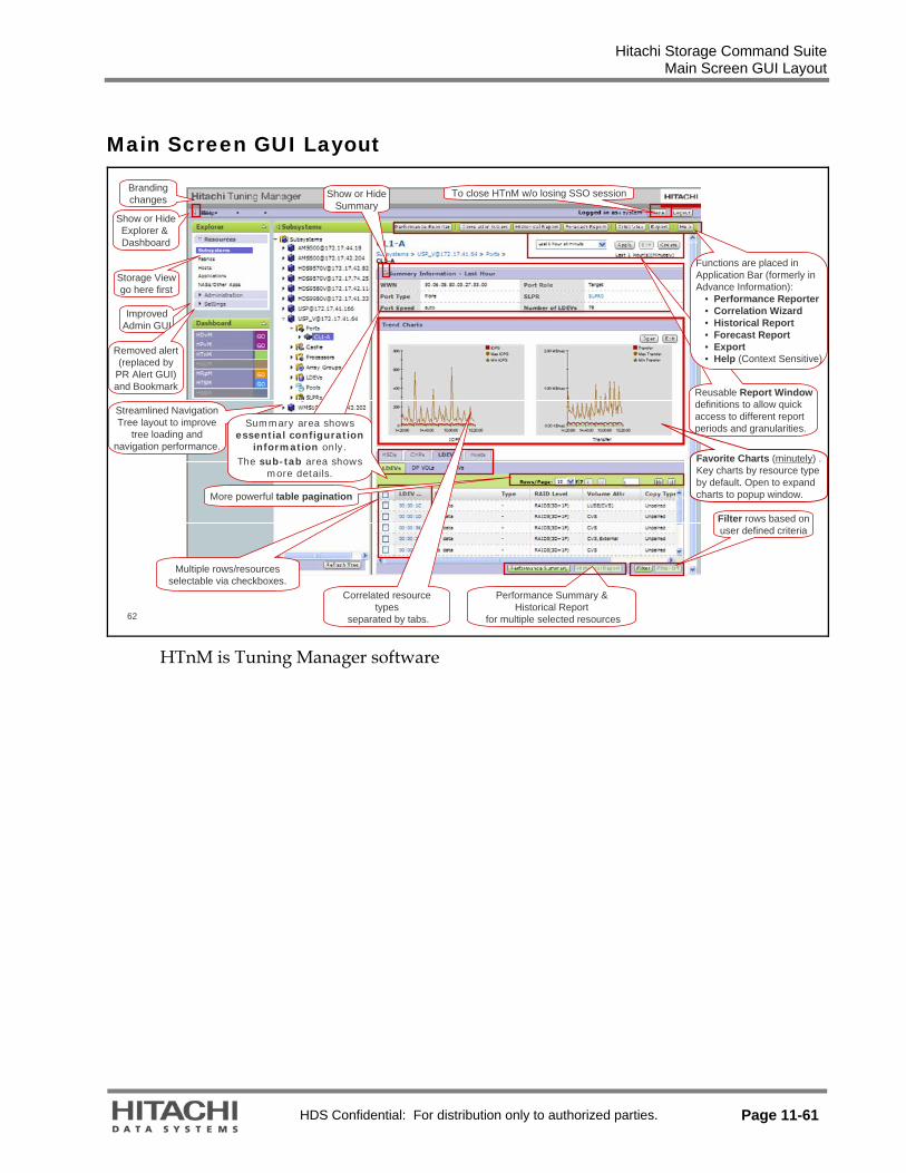
Hitachi Storage Command Suite Main Screen GUI Layout
HDS Confidential: For distribution only to authorized parties. Page 11-61
Main Screen GUI Layout
62
Brandingchanges
Show or HideExplorer & Dashboard
Storage Viewgo here first
ImprovedAdmin GUI
Removed alert(replaced by
PR Alert GUI)and Bookmark
Streamlined NavigationTree layout to improve
tree loading and navigation performance.
To close HTnM w/o losing SSO session
Favorite Charts (minutely) .Key charts by resource type by default. Open to expand charts to popup window.
Filter rows based onuser defined criteria
Performance Summary & Historical Report
for multiple selected resources
Reusable Report Windowdefinitions to allow quickaccess to different report periods and granularities.
Functions are placed inApplication Bar (formerly in Advance Information):
• Performance Reporter• Correlation Wizard• Historical Report• Forecast Report• Export• Help (Context Sensitive)
Minimize Summary Information to display essential information only.
Details are stored in the sub-tab area.
Summary area shows essential configuration
information only.The sub-tab area shows
more details.
More powerful table pagination
Multiple rows/resourcesselectable via checkboxes.
Correlated resource types
separated by tabs.
Show or HideSummary
HTnM is Tuning Manager software

Hitachi Storage Command Suite V6.0 GUI Overview
Page 11-62 HDS Confidential: For distribution only to authorized parties.
V6.0 GUI Overview
63
Explorer Context Area
Explorer Area
Navigation Area

Hitachi Storage Command Suite Global Task Bar
HDS Confidential: For distribution only to authorized parties. Page 11-63
Global Task Bar
64
• Call Performance Reporter
The Performance Reporter provides one way of checking the capability of an installed Agent to collect metrics from the resources and communicate with the Tuning Manager server.
If the selected report contains metric data, communication is verified between the agent instance and the Tuning Manager server.

Hitachi Storage Command Suite Application Bar Area
Page 11-64 HDS Confidential: For distribution only to authorized parties.
Application Bar Area
65
Performance Reporter – In-context launch of Performance Reporter

Hitachi Storage Command Suite Application Bar Area
HDS Confidential: For distribution only to authorized parties. Page 11-65
66
Correlation Wizard – Shows trend charts of related resources.

Hitachi Storage Command Suite Application Bar Area
Page 11-66 HDS Confidential: For distribution only to authorized parties.
67
Historical Reports – Show trend charts about the resource displayed on title area.
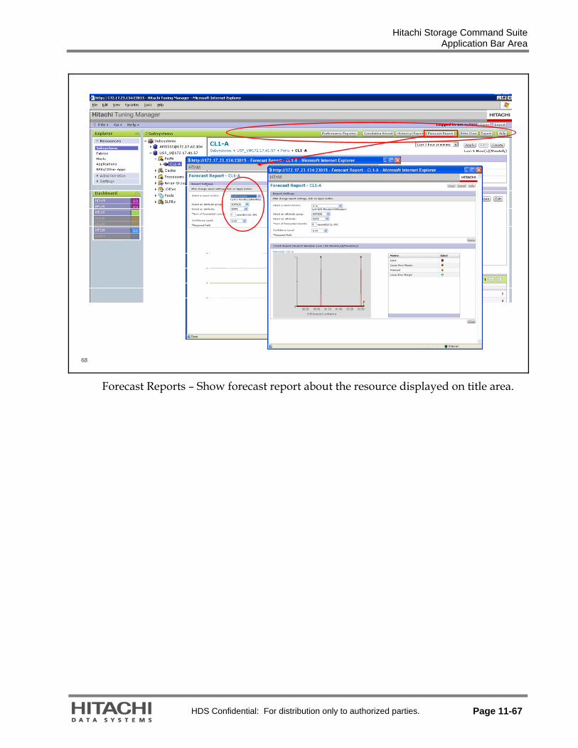
Hitachi Storage Command Suite Application Bar Area
HDS Confidential: For distribution only to authorized parties. Page 11-67
68
Forecast Reports – Show forecast report about the resource displayed on title area.

Hitachi Storage Command Suite Application Bar Area
Page 11-68 HDS Confidential: For distribution only to authorized parties.
69
Print View – Prints out report in the current window
Export – Exports all data shown in main screen. CSV format is supported
Help – Shows context sensitive help about main screen in separate windows

Hitachi Storage Command Suite Explorer and Navigation Area
HDS Confidential: For distribution only to authorized parties. Page 11-69
Explorer and Navigation Area
70
• Correlation without Host Agent Installed
The tree structure in the Navigation Area for the selected resource Subsystem is listing the supported storage systems by type and IP address. Detail information of any selected Sub-structure of a Subsystem will be displayed in the Application Area.

Hitachi Storage Command Suite Explorer and Navigation Area
Page 11-70 HDS Confidential: For distribution only to authorized parties.
71
• Additional Information with Host Agent Installed
• Resource – Subsystem

Hitachi Storage Command Suite Explorer and Navigation Area
HDS Confidential: For distribution only to authorized parties. Page 11-71
Explorer and Navigation Area
73
• Resource – Fabrics and Hosts
The Resource Fabrics is grouped by Vendors in the Navigation Area. Details of the switches in a fabric as well as their ports are shown in the Application Area.
Hosts are grouped by Operation System in the Navigation Area and detailed information of a selected host is provided in the Application Area.

Hitachi Storage Command Suite Link Management Software
Page 11-72 HDS Confidential: For distribution only to authorized parties.
Link Management Software
74
Business ApplicationModules
Storage OperationsModules
Basic Operating System
Hitachi Storage Specific HeterogeneousHeterogeneous
Device Manager
API – CIM/SMI-S Provisioning Configuration Replication Configuration
Resource ManagerVirtual Partition
ManagerServer Priority
Manager
QoS Application ModulesQoS Application ModulesOracle Oracle -- Exchange Exchange -- Sybase Sybase --SQL Server SQL Server –– NetAppNetApp OptionOption
QoS for QoS for File ServersFile Servers
SRMSRM
ChargebackChargeback PathPathProvisioningProvisioning Global Global
ReporterReporter
Storage Services Manager Storage Services Manager
Backup Backup Services Services ManagerManager
Tiered Storage Manager
Replication Monitor
Tuning Manager
Dynamic Link ManagerDynamic Link ManagerPath failover and failback load balancingPath failover and failback load balancing
Global Link ManagerGlobal Link Manager Protection Manager
Exchange - SQL Server
Reporting
Universal Volume Manager
Performance Monitor
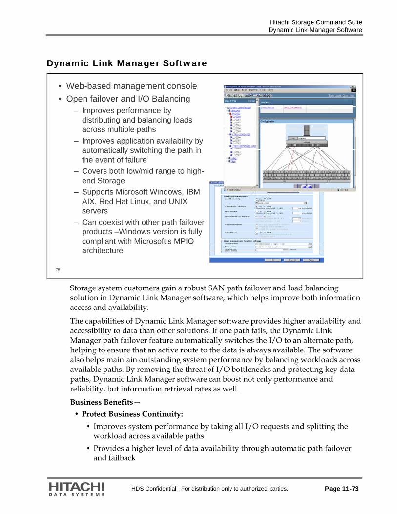
Hitachi Storage Command Suite Dynamic Link Manager Software
HDS Confidential: For distribution only to authorized parties. Page 11-73
Dynamic Link Manager Software
75
• Web-based management console• Open failover and I/O Balancing
– Improves performance by distributing and balancing loads across multiple paths
– Improves application availability by automatically switching the path in the event of failure
– Covers both low/mid range to high-end Storage
– Supports Microsoft Windows, IBM AIX, Red Hat Linux, and UNIX servers
– Can coexist with other path failover products –Windows version is fully compliant with Microsoft’s MPIO architecture
Storage system customers gain a robust SAN path failover and load balancing solution in Dynamic Link Manager software, which helps improve both information access and availability.
The capabilities of Dynamic Link Manager software provides higher availability and accessibility to data than other solutions. If one path fails, the Dynamic Link Manager path failover feature automatically switches the I/O to an alternate path, helping to ensure that an active route to the data is always available. The software also helps maintain outstanding system performance by balancing workloads across available paths. By removing the threat of I/O bottlenecks and protecting key data paths, Dynamic Link Manager software can boost not only performance and reliability, but information retrieval rates as well.
Business Benefits— Protect Business Continuity:
Improves system performance by taking all I/O requests and splitting the workload across available paths
Provides a higher level of data availability through automatic path failover and failback

Hitachi Storage Command Suite Dynamic Link Manager Software
Page 11-74 HDS Confidential: For distribution only to authorized parties.
Enables access to data on all Sun/Hitachi storage systems in both direct-attached storage and storage area network environments with path failover and I/O balancing over multiple HBA cards
Improve Productivity and Processes: Eases installation and operation through the auto-discovery function Supports path failover and I/O balancing for the latest versions of IBM AIX, Microsoft Windows, HP-UX, Sun Solaris, and Linux operating systems, as well as numerous clustering environments
Coexists with other path-failover products Supports and compliments MPIO in Windows environments Includes graphical user interface and command-line interface Provides a Web browser and link and launch capabilities from Device Manager software
Provides manual and automatic failover and failback support Monitors the status of online paths through a health-check facility at customer-specified intervals and places a failed path offline when an error is detected

Hitachi Storage Command Suite Global Link Manager Software
HDS Confidential: For distribution only to authorized parties. Page 11-75
Global Link Manager Software
76
• Features– Group Management– Advanced Reporting– Common UI
• Eliminates many single-host multipathing operational headaches
– Manages various servers’ multiple paths from a single console
– Simplifies storage maintenance activities while at the same time making it less disruptive
– Path failures can be quickly identified and addressed so that availability and performance of critical applications is not impacted
– Makes it easier to make adjustments that will eliminate I/O bottlenecks.
– Keeps customers informed near real-time on the status of all their multiple paths
Manage the entire Dynamic Link Manager software multipathing environment from a single console—
For each Dynamic Link Manager software instance, you can list the path information for all paths or for each host, HBA port, storage system, and storage port.
Aggregated path views corresponding to path status (online or offline) provides an easy way to check the health of the entire multipathing environment.
Adjust the online/offline path status for single or multiple hosts Adjust load balancing for individual LUs
Management capabilities are based on common user role definitions
Event Notification— Alerts generated by Dynamic Link Manager software are displayed by Global Link Manager Software near real-time
Immediate notification of potential problems reduces the risk of unscheduled downtime
Troubleshooting capabilities are enhanced as the location of the path failure can be easily pinpointed

Hitachi Storage Command Suite Global Link Manager Software
Page 11-76 HDS Confidential: For distribution only to authorized parties.
Group Management— Control access to a specific “group” of hosts (subset of Dynamic Link Manager software instances).
Allows managing a subset of hosts as a single unit Resource Groups provide separate System Administrators the capability to securely manage their own set of hosts
Host Groups provides each individual user with the capability to create a customized management view tailored to fit their operational needs
Advanced Reporting — Offers real-time and historically on all managed storage paths

Hitachi Storage Command Suite Dynamic Link Manager Software Features
HDS Confidential: For distribution only to authorized parties. Page 11-77
Dynamic Link Manager Software Features
77
• Failover and failback• Auto discovery• Scheduling algorithms/load
balancing• Persistent reserves• Cluster aware• Path Health Checking• Dynamic path reconfiguration*
LAN
SAN
LU2
LU1
LU3
HBA
LU2
LU1
LU3
HBA HBA
LU2
LU1
LU3
HBA HBAHBA
Auto discovery — Automatic path configuration
Load Balancing Algorithms— Failover Round robin Extended round robin
Note: IBM® AIX® automatic failback is not default
* Dynamic path reconfiguration is not available for all operating systems.

Hitachi Storage Command Suite Global Link Manager Software Features
Page 11-78 HDS Confidential: For distribution only to authorized parties.
Global Link Manager Software Features
78
• Single unified GUI• Manages multiple instances• Simplified path maintenance
activity• Scheduling algorithms by
HDEV (LU)• Alert notifications• Provides secure resource
grouping
LAN
SAN
LU2
LU1
LU3
HBA
LU2
LU1
LU3
HBA HBA
LU2
LU1
LU3
HBA HBAHBA
Event Notification — Alerts generated by Dynamic Link Manager software are displayed by Global Link Manager software near real-time.
Path Management — Global view of paths and HDEVs for all Dynamic Link Manager software instances. Management capabilities are based on user role definitions.
Host Management — Centrally manages configuration of all Dynamic Link Manager software instances.
Host Group Management — A customized grouping of hosts created by an individual user.
Resource Group Management — Administrator controls user’s access to a specific group of hosts (subset of Dynamic Link Manager software instances).
Access Control — User role definitions control operational and host resource access.

Hitachi Storage Command Suite Global Link Manager Software Features
HDS Confidential: For distribution only to authorized parties. Page 11-79
79
• Graphical User Interface
Dashboard
Explorer
Application Area
Object Tree
Global Task Bar
Application Bar

Hitachi Storage Command Suite Global Link Manager Software Features
Page 11-80 HDS Confidential: For distribution only to authorized parties.
80
• Global Link Manager software load balancing for each Multipath LU
Load balancing configuration set by Global Link Manager software overrides those set by Dynamic Link Manager software.
Selected HDev
HBA
HDev HDev
HBAPort Port
HDev HDev
Port Port
SubsystemCHA Port CHA Port
Round Robin
Extended Round Robin
Disabled
Following Host
Setting
DynamicLink
Managersoftware:
Round Robin
This feature is only available through Global Link Manager software.
Global Link Manager software can set each HDEV(LU) load balancing algorithm only toward Dynamic Link Manager software v5.8, which enables optimization of I/O performance according to application characteristics.
Note: CHA means channel adapter

Hitachi Storage Command Suite Global Link Manager Software Features
HDS Confidential: For distribution only to authorized parties. Page 11-81
81
• Alert Management– SNMP setting can be configured only through Global Link Manager software
Updated every minute
The alert information detected in Dynamic Link Manager software is notified as SNMP trap to the server.
The alerts received by the server are stored in the database(DB). During display of the next screen, the latest alert information is displayed on the browser.
Notification of the alerts can be identified from the Dashboard menu. The user can then view the details by displaying the alerts list.
Minimum setting is one minute.

Hitachi Storage Command Suite Global Link Manager Software Features
Page 11-82 HDS Confidential: For distribution only to authorized parties.
82
• SNMP Forwarding– A single Global Link Manager server can manage alerts from up to 1,000
hosts. – SNPM forwarding to a third party management console allows you to increase
the number of manageable alerts
HGLM 5.0Server #1
Web Browser
Storage Subsystems
HDLM5.8 or later
HDLM5.8 or later
Up to 1,000 hosts……
HGLM 5.0Server #4
HDLM5.8 or later
HDLM5.8 or later
Up to 1,000 hosts……
HGLM 5.0Server #2
HDLM5.8 or later
HDLM5.8 or later
Up to 1,000 hosts……
…………(3) Managementoperations
AlertsAlerts Alerts
3rd Party SNMP management console(Tivoli, CA, OpenView, for example)
(1) Forwarded Alerts
(2) View alerts
Consolidated management of multiple Global Link Manager servers using SNMP forwarding:
Must edit server.properties file for SNMP forwarding.
In the diagram and following pages,
HGLM stands for Global Link Manager.
HDLM stands for Dynamic Link Manager.

Hitachi Storage Command Suite Global Link Manager Software Features
HDS Confidential: For distribution only to authorized parties. Page 11-83
83
• Automatic Host Refresh– Host information can be updated automatically during a specified period of
time.
Host1
Global Link Manager
Host2 Host3 Host4
1
2 3
4
HGLM Host1 Host2 Host3 Host4
SpecifiedInterval
IndividualInterval

Hitachi Storage Command Suite Global Link Manager Software Features
Page 11-84 HDS Confidential: For distribution only to authorized parties.
84
• Historical Path Reporting– Knowing the history of a path is important in helping you understand what
happened:• Which host and path• Downtime (how many times and for how long)• Number of errors• Availability
Historical path reporting helps customers with many Dynamic Link Manager server quickly determine there are no path issues.
Collection of historical data is disabled by default. To enable collection of historical report data edit the server.properties file:
Value to be modify: getlogs.pathreport.get_mode=1
Value ‘0’ is disabled.
Value ‘1’ is enabled.

Hitachi Storage Command Suite Global Link Manager Software Features
HDS Confidential: For distribution only to authorized parties. Page 11-85
85
• Link and Launch Feature
Global Link Manager v5.6 and later can co-exist on the same server with Device Manager.
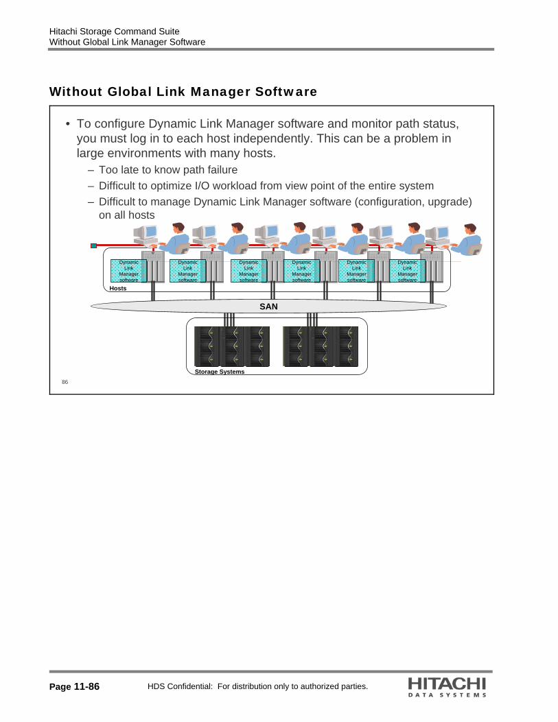
Hitachi Storage Command Suite Without Global Link Manager Software
Page 11-86 HDS Confidential: For distribution only to authorized parties.
Without Global Link Manager Software
86
• To configure Dynamic Link Manager software and monitor path status, you must log in to each host independently. This can be a problem in large environments with many hosts.
– Too late to know path failure– Difficult to optimize I/O workload from view point of the entire system– Difficult to manage Dynamic Link Manager software (configuration, upgrade)
on all hosts
Hosts
SAN
Storage Systems
DynamicLink
Managersoftware
DynamicLink
Managersoftware
DynamicLink
Managersoftware
DynamicLink
Managersoftware
DynamicLink
Managersoftware
DynamicLink
Managersoftware
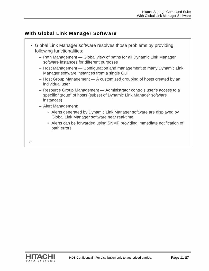
Hitachi Storage Command Suite With Global Link Manager Software
HDS Confidential: For distribution only to authorized parties. Page 11-87
With Global Link Manager Software
87
• Global Link Manager software resolves those problems by providing following functionalities:
– Path Management — Global view of paths for all Dynamic Link Manager software instances for different purposes
– Host Management — Configuration and management to many Dynamic Link Manager software instances from a single GUI
– Host Group Management — A customized grouping of hosts created by an individual user
– Resource Group Management — Administrator controls user’s access to a specific “group” of hosts (subset of Dynamic Link Manager software instances)
– Alert Management:• Alerts generated by Dynamic Link Manager software are displayed by
Global Link Manager software near real-time • Alerts can be forwarded using SNMP providing immediate notification of
path errors

Hitachi Storage Command Suite Dynamic Link Manager Software and Global Link Manager Working Together
Page 11-88 HDS Confidential: For distribution only to authorized parties.
Dynamic Link Manager Software and Global Link Manager Working Together
88
GlobalLink
AvailabilityManager software
Global LinkAvailabilityManagersoftwareserver Web Browser Web Browser Web Browser
Global Link Manager software Clients (GUI)
Hosts
SAN
Storage Systems
DynamicLink
Managersoftware5.2 to 5.7
DynamicLink
Managersoftware
5.8 or later
DynamicLink
Managersoftware
5.8 or later
DynamicLink
Managersoftware
5.8 or later
DynamicLink
Managersoftware
5.8 or later
DynamicLink
Managersoftware5.2 to 5.7
DeviceManagersoftware
Agent3.5 or later
DeviceManagersoftware
Agent3.5 or later

Hitachi Storage Command Suite Global Link Manager Software Architecture
HDS Confidential: For distribution only to authorized parties. Page 11-89
Global Link Manager Software Architecture
89
ProductionServer (Host)
StorageSystem
Fabric (SAN)Dynamic Link Manager
software Agent
Dynamic Link Manager software
Process Boundary
Explanatory notes:
Global Link Manager software Component
Management Server
HTTP
Server
HBase
Global Link Manager
software GUI
Global Link Manager software
Server
Repository DBMS(HiRDB**)
HBase*
Servlet Container (HBase)
HTTPXML
Global Link Manager software
RepositoryIntegratedRepository
IP Network (LAN)ManagementClient
HTTPWeb
Browser
Client
Command Line Interface (CLI)
Management
* HBASE = Common Components
** HiRDB = Hitachi Relational Database
Global Link Manager software is a servlet which runs in the Common Components (HBASE) Servlet Container. The HBASE is a common component of the Hitachi Storage Command Suite software.
The repository consists of two parts: Common repository which contains common information across suite such as user information
Global Link Manager software repository which is dedicated to Global Link Manager software.
Global Link Manager software provides Dynamic Link Manager software integrated management facility by communicating with the Dynamic Link Manager software and agents on multiple hosts.

Hitachi Storage Command Suite Global Link Manager Software Architecture
Page 11-90 HDS Confidential: For distribution only to authorized parties.
90
Base service Agent(Web Server)
Dynamic Link Manager software
Manager
Dynamic Link Manager software Drivers
Dynamic Link Manager software
Tools
Dynamic Link Manager software(v5.8 and later)
Common Agent
Agent ToolsAgent ToolsDevice Manager software Agent
Device Manager software Agent
Device Manager software Agent (v5.0 and later)
Device Manager software Server
Communicate to Server (Device Manager software Server and/or Global Link Manager software
Server)
(Port 24041, 24042)
Global Link Manager software
Server
The new agent component, HBsA (Base service Agent) takes care of the communication between the agents and the server component (Device Manager software server and/or Global Link Manager software server)
The HBsA component and runtime environment (JRE) are included in both Device Manager software Agent and Dynamic Link Manager software (v5.8 and later) packages.
The agent and Dynamic Link Manager software installer will not overwrite the common component when the newer version is already installed.

Hitachi Storage Command Suite Global Link Manager Software Architecture
HDS Confidential: For distribution only to authorized parties. Page 11-91
91
Coexistence of Device Manager software Agent and Common Agent (v4.3 and v5.8)
Device Manager software Agent (v4.3 and earlier)
Agent ToolsAgent Tools
Device Manager software Agent(Web Server)
Device Manager software Agent(Web Server)
Device Manager
software Agent
Device Manager
software Agent
Communicate to Device Manager software Server
(Port 23011,23013)
Communicate to Global Link
Manager software Server (Port 24041,
24042)
Host
Base service Agent (Web Server)
Base service Agent (Web Server)
Dynamic Link Manager
software Manager
Dynamic Link Manager
software Manager
Dynamic Link Manager softwareDrivers
Dynamic Link Manager softwareDrivers
Dynamic Link Manager software
Tools
Dynamic Link Manager software
Tools
Dynamic Link Manager software (v5.8 and later)
Global Link Manager software Server
Global Link Manager software Server
Device Manager software Server
Device Manager software Server
If Dynamic Link Manager software version 5.8 and Device Manager software Agent v4.3 or earlier are installed on the same host, the Common Agent and the Device Manager software Agent will coexist. They will use distinctive ports to communicate with Global Link Manager software or Device Manager software servers.

Hitachi Storage Command Suite
Page 11-92 HDS Confidential: For distribution only to authorized parties.

HDS Confidential: For distribution only to authorized parties. Page 12-1
12. Hitachi Storage Command Suite
This section is part 2 of Storage Command Suite. Part 1 of this module covered:
Device Manager software
Tuning Manager software
Dynamic Link Manager software
Global Link Manager software

Hitachi Storage Command Suite Tiered Storage Manager Software
Page 12-2 HDS Confidential: For distribution only to authorized parties.
Tiered Storage Manager Software
2
Business ApplicationModules
Storage OperationsModules
Basic Operating System
Hitachi Storage Specific HeterogeneousHeterogeneous
Device Manager
API – CIM/SMI-S Provisioning Configuration Replication Configuration
Resource ManagerVirtual Partition
ManagerServer Priority
Manager
QoS Application ModulesQoS Application ModulesOracle Oracle -- Exchange Exchange -- Sybase Sybase --SQL Server SQL Server –– NetApp OptionNetApp Option
QoS for QoS for File ServersFile Servers
SRMSRM
ChargebackChargeback PathPathProvisioningProvisioning Global Global
ReporterReporter
Storage Services Manager Storage Services Manager
Backup Backup Services Services ManagerManager
Tiered Storage Manager
Replication Monitor
Tuning Manager
Dynamic Link ManagerDynamic Link ManagerPath failover and failback load balancingPath failover and failback load balancing
Global Link ManagerGlobal Link Manager Protection Manager
Exchange - SQL Server
Reporting
Universal Volume Manager
Performance Monitor

Hitachi Storage Command Suite Product Description
HDS Confidential: For distribution only to authorized parties. Page 12-3
Product Description
3
Hitachi Enterprise Storage Systems
SAN
Hitachi Enterprise Storage Systems
SAN
Hitachi EMCHPSun
• Simplifies the identification, classification, and movement of any data volume internal to or attached to the Hitachi enterprise storage system
• Purpose is to allocate each volume to its optimal tier of storage
• Fundamental building block of Application Optimized Storage
Objective: Virtualization-enabled Data Migration For Storage Optimization
Microsystems
Tiered Storage Manager software is a data management product that simplifies the identification, classification, and movement of any data volume internal to or attached to the Hitachi storage systems. The purpose is to allocate each volume to its optimal tier of storage. Tiered Storage Manager enables efficient storage tier management based on volume metrics that characterize an application’s required quality of storage service. It is unique because it allows moving an application’s data between tiers without needing to quiesce the application. This is a nice feature for applications that can be quiesced, and a critical one for applications that can not. It is useful for users with diverse applications with varying, and maybe even conflicting, requirements for capacity, performance, access, security, and archival and retention requirements. And, for applications which have needs which may vary over time, Tiered Storage Manager software is a key foundation or enabler of the Application Optimized Storage. It simplifies the task of optimizing storage infrastructure to satisfy the cost, performance, availability, and functionality requirements of applications. It helps organizations respond to changes driven by the business units by managing data movement so that storage meets or exceeds changing service level agreements. It simplifies general purpose data migration including array retirement and eliminates application interruptions during data migration. In the diagram above, you can see that it works behind a Hitachi enterprise storage system and moves volumes to and from any internal or external storage (anything supported by the enterprise system).

Hitachi Storage Command Suite Product Position
Page 12-4 HDS Confidential: For distribution only to authorized parties.
Product Position
4
BackupBackupManagementManagement
ConfigurationConfigurationManagementManagement
PerformancePerformanceManagementManagement
Device Manager software
Path Provisioning software
ReplicationManager software
Storage Navigator program
Tuning Managersoftware
Protection Manager software
Daily Operations
Storage Navigator program
Tiered Storage Manager software
• Task View
This diagram shows the product positioning of Tiered Storage Manager software compared to Storage Navigator program.
This (especially Device Manager software) and the Storage Navigator program have many features in common, but are used in different situations. The Device Manager product is predominantly used for the daily storage administration tasks. For daily operations, the deeper functionality provided by Storage Navigator program is not necessary. The Storage Navigator functions are only necessary for one-time operations, such as, initial configuration of the storage subsystem and maintenance.
Backup management might be integrated with configuration management.

Hitachi Storage Command Suite Device Manager Compared
HDS Confidential: For distribution only to authorized parties. Page 12-5
Device Manager Compared
5
• Domains
• Tiers
• Migration groups
• Entities
• Hosts
• LUNS
• Configuration• Infrastructure
• Logins
• Permissions
• State change
Common ComponentsCommon ComponentsCommon
ComponentRepository
CommonComponentRepository
DeviceManagerDevice
Manager
DeviceManager
Repository
TieredStorageManager
TieredStorageManager
TieredStorageManager
Repository
Logical, not actual, view of key data stores for all products and components shown
Logical, not actual, view of key data stores for all products and components shown

Hitachi Storage Command Suite Technical Focus and Value
Page 12-6 HDS Confidential: For distribution only to authorized parties.
Technical Focus and Value
6
• Tiered Storage Manager Software– Is the tool for migrating data between heterogeneous storage devices – Simplifies the identification, classification and movement of volumes– Designed to be as simple and as easy to use as possible, and to reduce
training time– Is the hub for Services Oriented Storage Solutions solutions from Hitachi Data
Systems:• Performance, configuration and reconfiguration• Array retirement• Manage application’s storage using volume migration
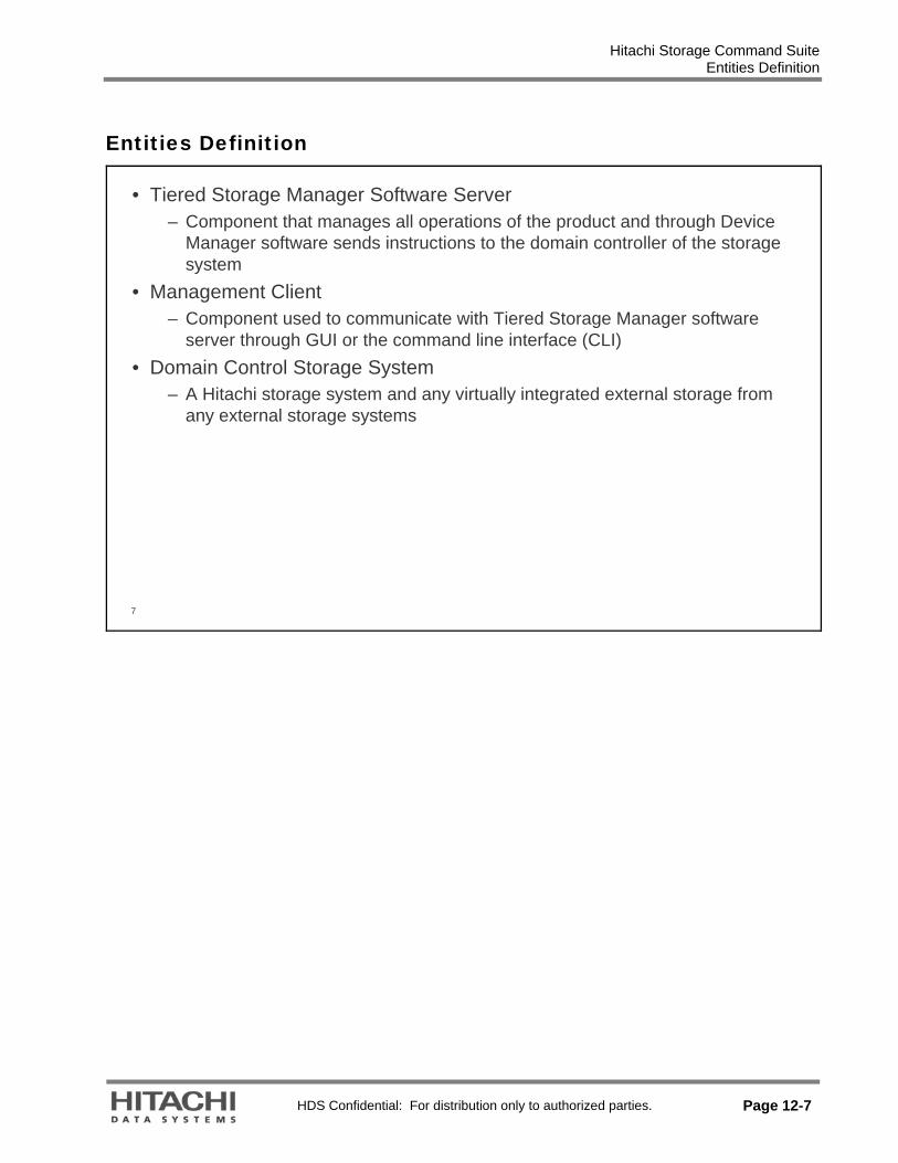
Hitachi Storage Command Suite Entities Definition
HDS Confidential: For distribution only to authorized parties. Page 12-7
Entities Definition
7
• Tiered Storage Manager Software Server – Component that manages all operations of the product and through Device
Manager software sends instructions to the domain controller of the storage system
• Management Client– Component used to communicate with Tiered Storage Manager software
server through GUI or the command line interface (CLI)• Domain Control Storage System
– A Hitachi storage system and any virtually integrated external storage from any external storage systems
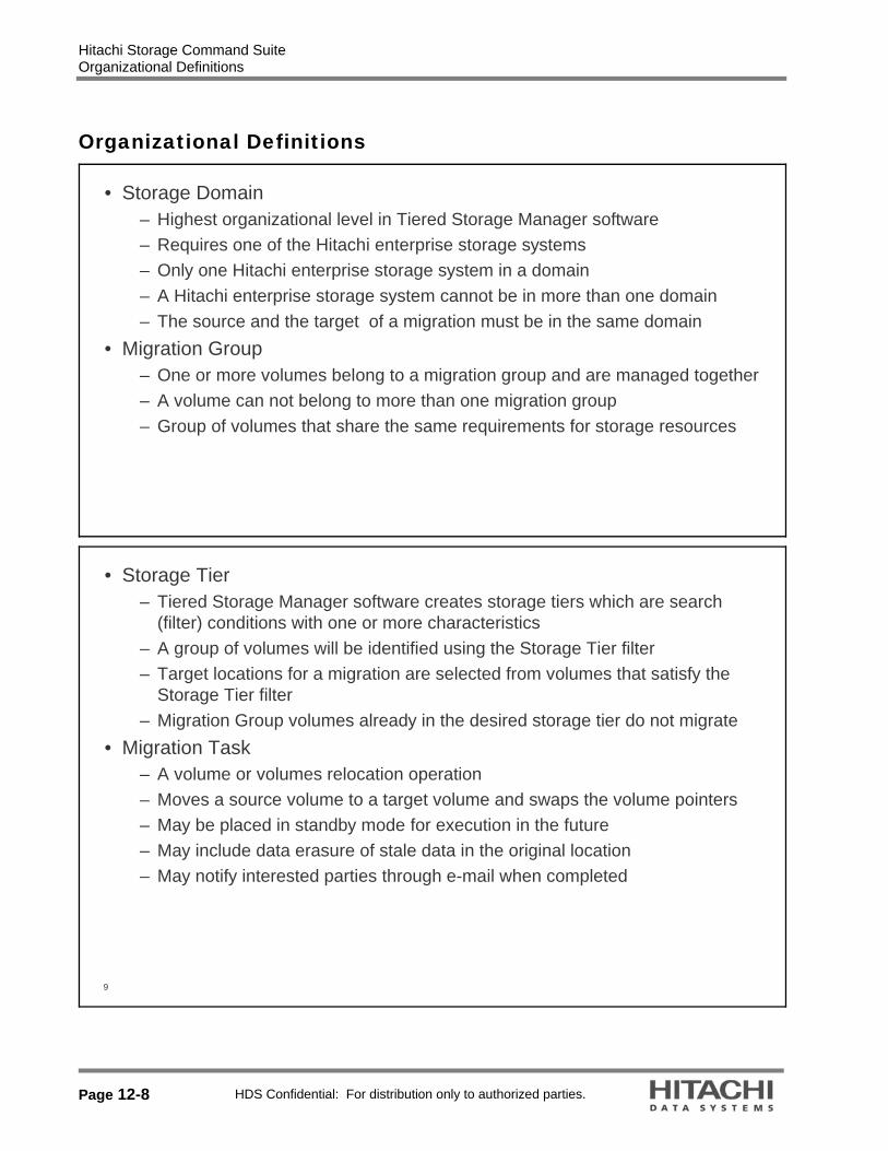
Hitachi Storage Command Suite Organizational Definitions
Page 12-8 HDS Confidential: For distribution only to authorized parties.
Organizational Definitions
• Storage Domain– Highest organizational level in Tiered Storage Manager software– Requires one of the Hitachi enterprise storage systems – Only one Hitachi enterprise storage system in a domain– A Hitachi enterprise storage system cannot be in more than one domain– The source and the target of a migration must be in the same domain
• Migration Group– One or more volumes belong to a migration group and are managed together– A volume can not belong to more than one migration group– Group of volumes that share the same requirements for storage resources
9
• Storage Tier– Tiered Storage Manager software creates storage tiers which are search
(filter) conditions with one or more characteristics– A group of volumes will be identified using the Storage Tier filter – Target locations for a migration are selected from volumes that satisfy the
Storage Tier filter– Migration Group volumes already in the desired storage tier do not migrate
• Migration Task– A volume or volumes relocation operation– Moves a source volume to a target volume and swaps the volume pointers– May be placed in standby mode for execution in the future– May include data erasure of stale data in the original location– May notify interested parties through e-mail when completed

Hitachi Storage Command Suite Graphical User Interface
HDS Confidential: For distribution only to authorized parties. Page 12-9
Graphical User Interface
10
Explorer Area
Dashboard Area
Global Menu Bar
Application Area
Explorer Context Area
Navigation Area
Global Menu Bar Displays the function menus and action buttons that are used with Tiered Storage Manager, as well as information about the logged-in user. Explorer Area Displays the Tiered Storage Manager menu items. Choosing a menu item displays the corresponding information in the navigation area and the application area. The Explorer menu can be collapsed. Dashboard Area Displays a list of Storage Command Suite products. An enabled product can be started by clicking its Go button. The Dashboard can be collapsed. Navigation area Displays in tree format the objects that belong to the menu item chosen from the Explorer menu. When you expand the object tree and choose a desired object, information about the selected object-name appears in the explorer context area. Application area Provides summary Information Explorer Context area Displays information about the object that was chosen from the Explorer menu and object tree.

Hitachi Storage Command Suite Basic Functions
Page 12-10 HDS Confidential: For distribution only to authorized parties.
Basic Functions
11
• Creating Storage Domains• Searching and filtering volumes• Creating migration groups• Creating storage tiers• Creating migration plans• Creating migration tasks• Scheduling migrations• Migrating volumes• Shredding volumes• E-mailing status messages• Locking volumes

Hitachi Storage Command Suite Migrating Data
HDS Confidential: For distribution only to authorized parties. Page 12-11
Migrating Data
12
• Use the following steps to migrate data with Tiered Storage Manager. • Steps 1 through 4 are performed before migration:
1. Create a storage domain.2. Create a migration group.3. Add to the migration group the volumes required to migrate.4. Create a storage tier.
• Steps 5 and 6 are used to perform the actual migration operation:5. Create a migration task.6. Execute the migration task.

Hitachi Storage Command Suite Standard Workflow
Page 12-12 HDS Confidential: For distribution only to authorized parties.
Standard Workflow
13
Start Create Storage Domain
Create Storage Domain
Save as Storage Tier
Save as Storage Tier
Save as Migration
Group
Save as Migration
Group
Migrate Now?
Migrate Now?Migrate
VolumesMigrate
VolumesMigration
CompletedMigration
CompletedFinish
ScheduleMigration
Date & Time
ScheduleMigration
Date & Time
Search VolumesSearch
Volumes
Automated process
E-mail Completion
Message
E-mail Completion
Message
Create Migration
Group
Create Migration
GroupCreate
Storage TierCreate
Storage Tier
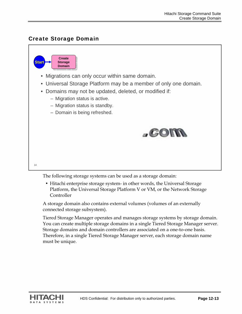
Hitachi Storage Command Suite Create Storage Domain
HDS Confidential: For distribution only to authorized parties. Page 12-13
Create Storage Domain
14
Start Create Storage Domain
Create Storage Domain
• Migrations can only occur within same domain.• Universal Storage Platform may be a member of only one domain.• Domains may not be updated, deleted, or modified if:
– Migration status is active.– Migration status is standby.– Domain is being refreshed.
The following storage systems can be used as a storage domain:
Hitachi enterprise storage system- in other words, the Universal Storage Platform, the Universal Storage Platform V or VM, or the Network Storage Controller
A storage domain also contains external volumes (volumes of an externally connected storage subsystem).
Tiered Storage Manager operates and manages storage systems by storage domain. You can create multiple storage domains in a single Tiered Storage Manager server. Storage domains and domain controllers are associated on a one-to-one basis. Therefore, in a single Tiered Storage Manager server, each storage domain name must be unique.

Hitachi Storage Command Suite Create Domain
Page 12-14 HDS Confidential: For distribution only to authorized parties.
Create Domain
15
1. Select Create Domain.
2. Choose from drop down list of suitable systems previously added to Device Manager.
Enter *Name, Description, and Logical DKC Number.
*Name (mandatory): Enter a name for the storage domain. This name will be used in Tiered Storage Manager to identify the storage system you have selected from Domain Ctrl.
Description: Enter a description for the storage domain that is to be created. Logical DKC Number: if the storage system you have selected from Domain Ctrl is Universal Storage Platform V, enter a logical DKC number to be used in the storage domain. The Logical DKC number should be 0 (currently).

Hitachi Storage Command Suite Created Domain
HDS Confidential: For distribution only to authorized parties. Page 12-15
Created Domain
16
Choosing a Storage Domain name from the navigation area or from the Storage Domains pane displays the Storage Domain Name pane that shows the property information in the application area.

Hitachi Storage Command Suite Search Attributes
Page 12-16 HDS Confidential: For distribution only to authorized parties.
Search Attributes
17
• Device Number• I/O Consumer• Volume Status• Subsystem• Subsystem Vendor• Subsystem Display
Model• Subsystem Serial
Number• Ctrl. Array Group• Array Group• AG Busy Rate• AG Max Busy Rate• RAID Level
• Disk Type• Capacity• Volume Lock
Status• Emulation Type• SLPR• CLPR• SYSPLEXID/DEVN• VOLSER• Logical Group• Port/HSD• Disk RPM• Disk Capacity
• P-VOLs Mig Group• P-VOLs MU Number• ShadowImage• TrueCopy Synch• TrueCopy Asynch• Universal Replicator• COW Snapshot• CVS• Dynamic Provisioning• Consumed Capacity• Consumed Capacity %• Pool ID• LDEV Label

Hitachi Storage Command Suite Filtering or Searching Volumes
HDS Confidential: For distribution only to authorized parties. Page 12-17
Filtering or Searching Volumes
18
• Migration Groups and Storage Tiers can both be created directly from the search facility.
• However, the following cannot be used as filter conditions for creating a storage tier:
– Device Number– I/O Consumer– Volume Status– Volume Lock Status– SYSPLEXID/DEVN– VOLSER– Logical Group– Port/HSD– P-VOLs Migration Group– P-VOLs MU Number– ShadowImage– TrueCopy Synchronous– TrueCopy Asynchronous– Universal Replicator– Copy-On-Write Snapshot– CVS– Consumed Capacity– Consumed Capacity Percentage– Pool ID– Label
Save as Storage Tier
Save as Storage Tier
Save as Migration
Group
Save as Migration
GroupSearch
VolumesSearch
Volumes
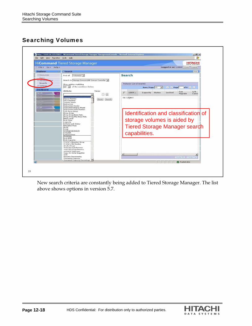
Hitachi Storage Command Suite Searching Volumes
Page 12-18 HDS Confidential: For distribution only to authorized parties.
Searching Volumes
19
Identification and classification of storage volumes is aided by Tiered Storage Manager search capabilities.
New search criteria are constantly being added to Tiered Storage Manager. The list above shows options in version 5.7.

Hitachi Storage Command Suite Create Storage Tier
HDS Confidential: For distribution only to authorized parties. Page 12-19
Create Storage Tier
20
Create Storage Tier
Create Storage Tier
To create storage tiers, it is necessary to first set up volume filter conditions and then search for the appropriate volumes in a storage domain. Storage tiers can then be created by saving these filter conditions as definitions.Storage tiers cannot be defined on the basis of LDEV numbers or volume status.As LDEV numbers can be selected during migration, a storage tier should be created that will contain the LDEV required to use as the storage target.
To migrate to a Dynamic Provision (DP) pool, pool filter conditions must be set up as the filter conditions for storage tiers. Free pool capacity can be used as the condition for defining the storage tiers.Volume filter conditions and pool filter conditions cannot be specified at the same time.
Create a group of volumes to be managed as a storage tier from the Create Tier dialog box.

Hitachi Storage Command Suite Create Tier from Search
Page 12-20 HDS Confidential: For distribution only to authorized parties.
Create Tier from Search
Save as Storage Tier
Save as Storage Tier
Search VolumesSearch
Volumes
22

Hitachi Storage Command Suite Create Migration Group from Search
HDS Confidential: For distribution only to authorized parties. Page 12-21
Create Migration Group from Search
23
Save as Migration
Group
Save as Migration
Group
Search VolumesSearch
Volumes
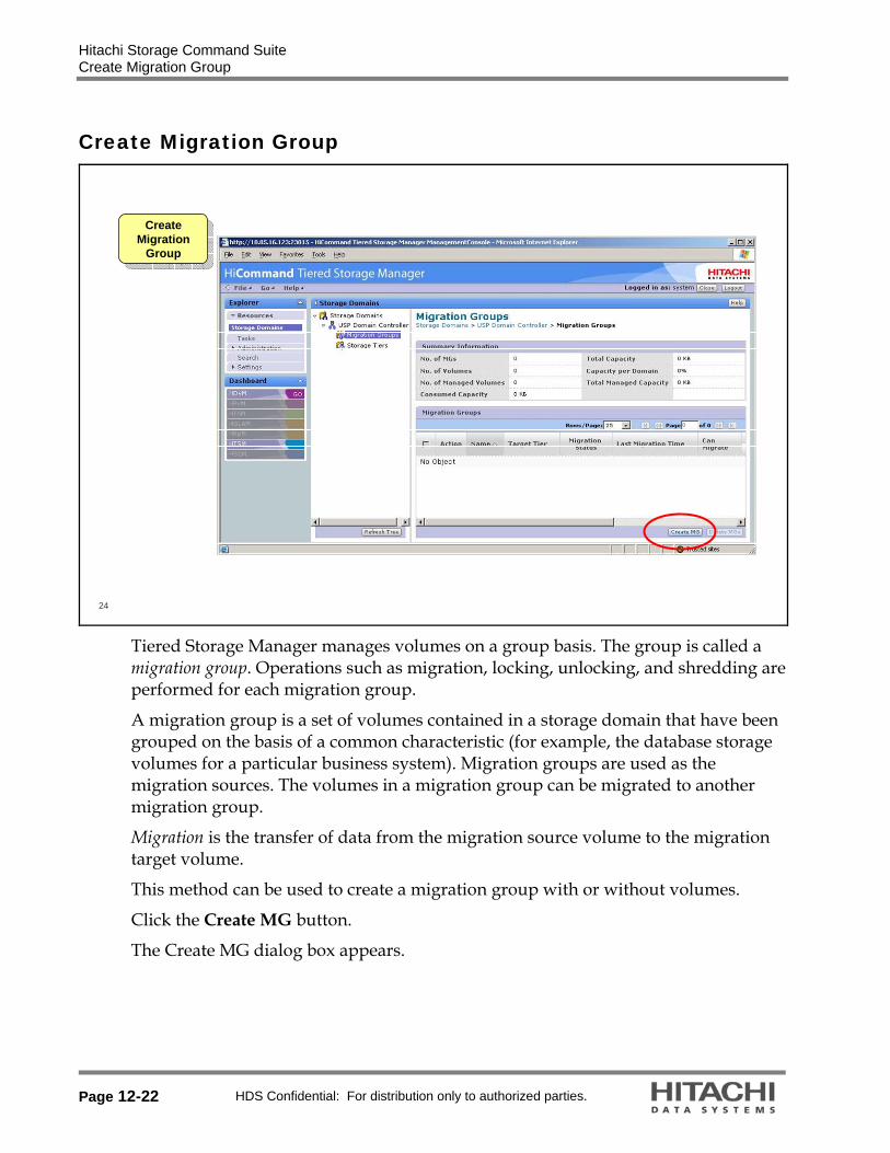
Hitachi Storage Command Suite Create Migration Group
Page 12-22 HDS Confidential: For distribution only to authorized parties.
Create Migration Group
24
Create Migration
Group
Create Migration
Group
Tiered Storage Manager manages volumes on a group basis. The group is called a migration group. Operations such as migration, locking, unlocking, and shredding are performed for each migration group.
A migration group is a set of volumes contained in a storage domain that have been grouped on the basis of a common characteristic (for example, the database storage volumes for a particular business system). Migration groups are used as the migration sources. The volumes in a migration group can be migrated to another migration group.
Migration is the transfer of data from the migration source volume to the migration target volume.
This method can be used to create a migration group with or without volumes.
Click the Create MG button.
The Create MG dialog box appears.

Hitachi Storage Command Suite Create Migration Group — General
HDS Confidential: For distribution only to authorized parties. Page 12-23
Create Migration Group — General
25
• Create MG screen has three tabs:
– General– Rule– Notification
• General requires a Name (mandatory),a Description (optional) and whether the group is allowed to be migrated (to prevent data from being migrated by mistake)
The Create MG dialog box is composed of three tabbed pages.
General page *Name (mandatory): Enter a name for the migration group. This name must be unique within the storage domain.
Description: Enter a description for the migration group that is to be created. Can Migrate: Specify whether the migration group is to be migrate-able. Select No for a group that is not migrated.
Clicking the Add Volumes button displays the Add Volume dialog box. From the list of volumes, select the check boxes for the volumes that are to be added, and then click OK.
To add to a migration group volumes that are already included in another migration group, select the Allow moving volumes from other Migration Groups checkbox. The selected volumes are deleted from the other migration group and added to the created migration group.

Hitachi Storage Command Suite Create Migration Group — Rule
Page 12-24 HDS Confidential: For distribution only to authorized parties.
Create Migration Group — Rule
26
• Maximum Coverage• Maximizing I/O throughput
• Minimum Coverage• Minimizing management time and risk
• Balance Capacity• Balance available capacity across array groups
• Manual adjustment always available
• Rule allows Migrations to be spread over the maximum (or minimum) number of Array Groups
Rules page
Array Group Selection: Selects the selection method for array groups. Migration Group List: Displays a list of migration groups. If there are migration groups that are to be specified for array group avoidance, select them and click the Add button.
Array Group Avoidance of Migration Groups: Displays a list of migration groups set for array group avoidance.
If there are any migration groups that you do not want to set for array group avoidance are displayed, select them, and then click the Delete button.
Spreading volumes for an application across multiple Array Groups can improve application responsiveness.
Tiered Storage Manager now has three different policy choices for automating the selection of Migration Targets for a Migration Group. Policy selection can be set to:
Maximum coverage – Over the most array groups to maximize I/O throughput Minimum coverage – Over the fewest array groups, to simplify management Balance Capacity– To balance capacity over available array groups.

Hitachi Storage Command Suite Create Migration Group — Rule
HDS Confidential: For distribution only to authorized parties. Page 12-25
Note that no matter which option is chosen, once Tiered Storage Manager allocates volumes to array groups, the user can manually override the placement of volumes to any array group within the target tier.
In addition, there is an option to avoid other migration groups. So, when creating one migration group, you can set a policy that when migrating those volumes they avoid volumes in other specified migration groups.
There are many situations where it is desirable to not have certain volumes reside in the same Array Group. For example P-VOLs and S-VOLs should not be placed in the same array group for performance and availability reasons.
Migration Groups can be customized so that when a migration occurs they will avoid placing their volumes into array groups that already contain volumes from a list of ten other migration groups.

Hitachi Storage Command Suite Create Migration Group — Notification
Page 12-26 HDS Confidential: For distribution only to authorized parties.
Create Migration Group — Notification
27
• Notification page– Email: E-mail address of
the user to be notified when an event is issued for the migration group that is being created.
– Date: Date when a specification period expiry event is to be issued for the migration group that is being created.
– Description: Message to be included in the notification e-mail when an event is issued for the migration group that is being created.
Notification page
Email: Enter the e-mail address of the user to be notified when an event is issued for the migration group that is being created.
Date: Set the date when a specification period expiry event is to be issued for the migration group that is being created.
Description: Enter the message to be included in the notification e-mail when an event is issued for the migration group that is being created.

Hitachi Storage Command Suite Create Migration Group — Adding Volumes
HDS Confidential: For distribution only to authorized parties. Page 12-27
Create Migration Group — Adding Volumes
28
•To Add Volumes:– Clicking the Add
Volumes button on the General tab displays the Add Volume dialog box.
– From the following pull-down menus, select the attributes to generate the required volumes to be added to the migration group.
1. In the Explorer menu, choose Search.
2. The navigation area displays items for constructing a search condition.
3. From the following pull-down menu, set the relevant items. Find all: Select Volume(s). Search from: Select a storage domain. Show entries matching: Select All or Any. Attribute: Select a search condition
4. Click Search.

Hitachi Storage Command Suite Adding Volumes from Logical Groups
Page 12-28 HDS Confidential: For distribution only to authorized parties.
Adding Volumes from Logical Groups
29
When Device Manager logical groups are set up as a best practice, Tiered Storage Manager can leverage these significantly when defining migration jobs – that is, whole applications can be identified to move from one tier to another. This is an example of administrative scalability.

Hitachi Storage Command Suite Create Migration Group — Selecting Volumes
HDS Confidential: For distribution only to authorized parties. Page 12-29
Create Migration Group — Selecting Volumes
30
– From the final list of volumes, select the check boxes for the volumes that are to be added, and then click OK.
The application area displays the Search sub-window, which contains the search results.
1. Select the check boxes for the volumes that are to be grouped.
2. Click Create MG. The Create MG dialog box appears.
3. Specify the required information in the Create MG dialog box. You can add volumes to the migration group by clicking Add Volumes.
4. Click OK. The Create MG - Creating dialog box appears, followed by the processing result dialog box.
5. Click Close.

Hitachi Storage Command Suite Create Storage Tier
Page 12-30 HDS Confidential: For distribution only to authorized parties.
Create Storage Tier
31
• Click Create Tier. The Create Tier dialog box appears.Create
Storage TierCreate
Storage Tier
Create a group of volumes to be managed as a storage tier from the Create Tier dialog box.

Hitachi Storage Command Suite Create Storage Tier
HDS Confidential: For distribution only to authorized parties. Page 12-31
32
• Enter Name (mandatory) and Description (optional).
• Under *Filter Conditions, set the attribute, operator, and value required.
• Click Search to see which volumes match the filter conditions.

Hitachi Storage Command Suite Create Storage Tier
Page 12-32 HDS Confidential: For distribution only to authorized parties.
33
• The search results are displayed in Volume List.
• Select the + button to add another filter and continue until the Volume list matches that required.
• Click OK.• Click Close.
To set a volume filter condition and then create a group of volumes to be managed as a tier:
1. In the Explorer menu, choose Search. The navigation area displays items for constructing a search condition.
2. From the following menu, set the relevant item. Find all: Select Volume(s). Search from: Select a storage domain. Show entries matching: Select All or Any. Attribute: Select a search condition.
3. Click Search. The application area displays the Search sub-window containing the search results.
4. Click Create Tier. The Create Tier dialog box appears.
5. In the Create Tier dialog box, set up the necessary information. If you want to change the search condition, edit it and then click Search again.
6. Click OK. Create Tier - Creating dialog box appears, followed by the processing result dialog box.
7. Click Close.

Hitachi Storage Command Suite Key Concept–Storage Tier
HDS Confidential: For distribution only to authorized parties. Page 12-33
Key Concept–Storage Tier
34
• A Storage Tier is a saved search condition.• Example:
– RAIDlevel = RAID5– DriveType = FC– Disk RPM = 15000– Array Busy < 30%
• Note: As the tier is a saved search condition, the volumes that match at creation time may not match at migrationtime!
• The resulting volumes will be used as target volumes for migrations.
Storage tiers are potential target locations for Migration Groups (in other words, migrations).
The Tiered Storage Manager search is also used to identify tiers based on various attributes. This example illustrates a search for top tier volumes:
RAID-5 15K Fiber channel drives Where the current Array Group busy is low (less than 30%)
All the resulting volumes could be defined them as a tier, such as Tier 1.

Hitachi Storage Command Suite Description of Migration
Page 12-34 HDS Confidential: For distribution only to authorized parties.
Description of Migration
• A migration is defined as the movement of a Migration Group’s volumes from a source to a target storage asset (Storage Tier).
– Volume Migration software is leveraged to seamlessly migrate volumes while the applications performing I/Os remain active.
• When the Migration Group arrives in a storage tier, the migration group assumes the properties of the tier.
– This means that the storage tier’s RAID level, performance characteristics, and more become the Migration Group’s new properties once the group moves into that tier.
36
• There are two ways to move volumes:
– Using the Migrate MG dialog box– Using the Migration Wizard
• Both methods require the Modify user permission.
Migrate Now?
Migrate Now?Migrate
VolumesMigrate
VolumesMigration
CompletedMigration
CompletedFinish
Automated process
E-mail Completion
Message
E-mail Completion
Message
When you have finished creating a target volume group that is to be managed and a volume group that is to be managed as a tier, you can move volumes.
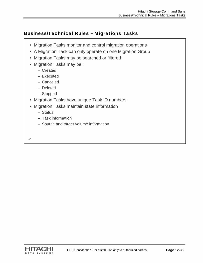
Hitachi Storage Command Suite Business/Technical Rules – Migrations Tasks
HDS Confidential: For distribution only to authorized parties. Page 12-35
Business/Technical Rules – Migrations Tasks
37
• Migration Tasks monitor and control migration operations• A Migration Task can only operate on one Migration Group• Migration Tasks may be searched or filtered • Migration Tasks may be:
– Created– Executed– Canceled– Deleted– Stopped
• Migration Tasks have unique Task ID numbers• Migration Tasks maintain state information
– Status– Task information– Source and target volume information

Hitachi Storage Command Suite Migration Task Description
Page 12-36 HDS Confidential: For distribution only to authorized parties.
Migration Task Description
38
• Migration Tasks:– Monitor and control migration
operations– Operate on only one
Migration Group– May be searched/filtered. – May be: created, executed,
canceled, deleted, or stopped
– Have unique Task ID numbers
– Maintain state information.• Status• Task information• Source and target volume
information

Hitachi Storage Command Suite Migration Task Description
HDS Confidential: For distribution only to authorized parties. Page 12-37
39
• The Migration Task Status can be monitored.
Migration Group is selected, and the Migrate button is clicked. Storage Tier is selected for the application’s new target destination – the radio button is selected.
Tiered Storage Manager sets up the initial target locations. Targets can be manually assigned.
Migrations can be delayed or immediately executed. Stale data can be erased. Fill in the desired selections. The final step is to confirm the Migration Plan The application volumes are relocated without interruption to the application Migration Tasks can be monitored Migration tasks for multiple Storage Domains can be monitored and managed all from a single console

Hitachi Storage Command Suite Migration Wizard
Page 12-38 HDS Confidential: For distribution only to authorized parties.
Migration Wizard
40
• From the global menu bar, choose Go, and then Migration Wizard. The wizard appears, providing an overview of the processing.
Using the Migration Wizard to Move Volumes:
Unlike when you perform migration by using the Migrate MG dialog box, the Migration Wizard enables you to create migration groups and storage tiers during the operation.
To move volumes using the Migration Wizard:
From the global menu bar, choose Go, and then Migration Wizard. Migration Wizard Step1 appears, providing an overview of the processing in the Migration Wizard dialog box.

Hitachi Storage Command Suite Migration Wizard
HDS Confidential: For distribution only to authorized parties. Page 12-39
41
• Selection of a Migration Group
Click Next. Migration Wizard Step2/6 appears, enabling you to select a migration group.
8. Select a migration group in the Migration Group list box.
9. To create a new migration group, click the Create MG button.
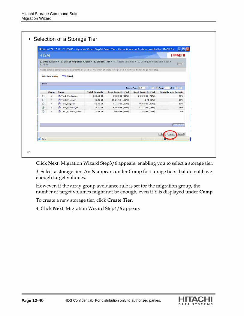
Hitachi Storage Command Suite Migration Wizard
Page 12-40 HDS Confidential: For distribution only to authorized parties.
42
• Selection of a Storage Tier
Click Next. Migration Wizard Step3/6 appears, enabling you to select a storage tier.
3. Select a storage tier. An N appears under Comp for storage tiers that do not have enough target volumes.
However, if the array group avoidance rule is set for the migration group, the number of target volumes might not be enough, even if Y is displayed under Comp.
To create a new storage tier, click Create Tier.
4. Click Next. Migration Wizard Step4/6 appears

Hitachi Storage Command Suite Migration Wizard
HDS Confidential: For distribution only to authorized parties. Page 12-41
43
• Match Volumes – Click the Auto Match Pairs button. Migration Volume Matching is executed automatically and Migration Wizard Step4/6 appears again.
• Check the contents of the migration volume pair that has been created automatically by Tiered Storage Manager.
• Migrations can only occur between volumes with the same number of blocks (Prior to V6.0).
• Click Edit Pairs.
5. Migration Wizard Step4/6 appears, enabling you to check the contents of the
migration volume pair that has been created automatically by Tiered Storage Manager.
6. Click the Auto Match Pairs button. Migration Volume Matching is executed automatically and Migration Wizard Step4/6 appears again.
Migrations can only occur between volumes with the same number of blocks (prior to V 6.0). The block count for a volume is an important attribute when looking for potential Migration Targets. From Tiered Storage Manager v5.5 software various displays in the GUI now report the LDEV’s Block Count.

Hitachi Storage Command Suite Migration Wizard
Page 12-42 HDS Confidential: For distribution only to authorized parties.
44
• Edit Pairs – Migration volume pairs to be changed
• To change the migration volume pair, select the edited pairs. When finished changing volume pairs, click OK.
• Specified volumes can be excluded from the migration.
• On the edit pair window, select the volume pairs (source volumes) and press Do not Migratebutton. If all pairs have the Do Not Migrate status, however, a migration task cannot be created.
The volumes that are specified as “Do not Migrate”
To change the migration volume pair: 7. Click Edit Migration Pairs. The Edit Migration Pairs dialog box appears, which
enables you to change migration volume pairs. 8. Select the edited pairs. 9. When you finish changing volume pairs, click OK. The Edit Migration Pairs
dialog box closes and Migration Wizard Step4/6 appears again. 10. Click Next. *Configuring Tiered Storage Manager software v 5.7.0 to operate the same as release 5.5.0 and earlier: Open the following properties file with a text editor : In Windows HTSM-server-installation-folder\conf\server.properties In Solaris # /opt/HiCommand/TieredStorageManager/conf/server.properties Add the following parameter to the end of the above-mentioned file: To change the current display about the migration destination candidate volumes to the previous method, add the following setting to the above-mentioned file: server.migrationPlan.candidateVolumeCountLimit=false (This setting means that there is no limit for the number of candidate volumes displayed when a migration plan is created.)

Hitachi Storage Command Suite Migration Wizard
HDS Confidential: For distribution only to authorized parties. Page 12-43
45
• Setting of options for the migration task to be created
• Use this window to set options for the execution timing of the created task and for data erasure after execution. Change the e-mail address for event notification if required.
• By default, the data on the migration source volume will not be erased after migration.
11. Migration Wizard Step5/6 appears, enabling you to set options for the migration
task to be created. Use this window to set options for the execution timing of the created task and for data erasure after execution. You can also change the email address for event notification.
12. Click Confirm. Note: In Tiered Storage Manager software v 5.5.0 and earlier, the checkbox in the Create Migration Plan dialog box and Migration Task Wizard - Step 5/6 window is selected by default (to erase the data). Since Tiered Storage Manager software v 5.7.0 the checkbox is not selected by default (do not erase data). *Configuring HTSM to operate the same as release 5.5.0 and earlier: Open the following properties file with a text editor : In Windows HTSM-server-installation-folder\conf\server.properties In Solaris # /opt/HiCommand/TieredStorageManager/conf/server.properties Add the following parameter to the end of the above-mentioned file: server.migration.dataErase.defaultValue=true (This setting means that the migration source volume data will be erased after a migration.)

Hitachi Storage Command Suite Migration Wizard
Page 12-44 HDS Confidential: For distribution only to authorized parties.
46
• If the option to execute immediately was selected in the previous step, the created task is executed automatically, that is, the migration is executed.
If you set the option for execution immediately after creation in Step 6, the created task is executed automatically (migration is executed). When task execution or migration task creation is completed, the end of the Migration Wizard Step 6 of 6 is displayed.

Hitachi Storage Command Suite Migration Wizard
HDS Confidential: For distribution only to authorized parties. Page 12-45
47
• Task execution or migration task creation is completed
• Click Finish.

Hitachi Storage Command Suite Migration Engine Operation
Page 12-46 HDS Confidential: For distribution only to authorized parties.
Migration Engine Operation
48
P-VOL
S-VOL
c0t0d0
LUslogical
PDEVsphysical
MigrationIn-progress
Can be an Internal Device
Swap Volume
Maps
Reserve
1. Application using c0t0d0 3. Migration in-progress
Can be an External Device
2. Migration starts 4. Migration nearly completed
5. Migration completed
1. A volume is migrated without interrupting the applications. The application is
using the volume c0t0d0.
2. Migration starts. A Reserve is placed upon the target volume. Any internal and external volumes can be used in the migration.
3. Data migration begins. The source volume is replicated upon the target.
4. Once the data is replicated the Volume Maps are swapped. Once swapped the application immediately starts using the target volume.
5. The migration completes by removing the reserve and cleaning up. The old stale data can be optionally erased.
Hitachi Storage Command Suite Schedule Migration
HDS Confidential: For distribution only to authorized parties. Page 12-47
Schedule Migration
49
ScheduleMigration
Date & Time
ScheduleMigration
Date & Time
Tiered Storage Manager software does not include a build-in scheduler. To schedule migration, use the CLI with any scheduler provided by the operating system, such as CRON on UNIX or AT on Windows.
If a task is not executed immediately, it is placed in standby status. Execute such a task using the ExecuteTask command specifying the task's ID.
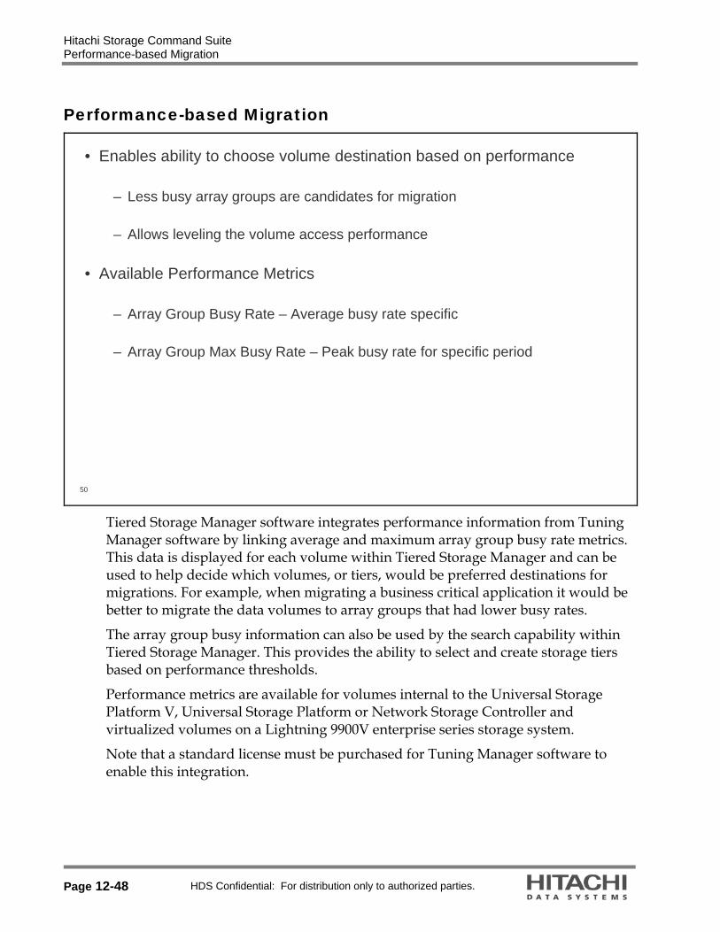
Hitachi Storage Command Suite Performance-based Migration
Page 12-48 HDS Confidential: For distribution only to authorized parties.
Performance-based Migration
50
• Enables ability to choose volume destination based on performance
– Less busy array groups are candidates for migration
– Allows leveling the volume access performance
• Available Performance Metrics
– Array Group Busy Rate – Average busy rate specific
– Array Group Max Busy Rate – Peak busy rate for specific period
Tiered Storage Manager software integrates performance information from Tuning Manager software by linking average and maximum array group busy rate metrics. This data is displayed for each volume within Tiered Storage Manager and can be used to help decide which volumes, or tiers, would be preferred destinations for migrations. For example, when migrating a business critical application it would be better to migrate the data volumes to array groups that had lower busy rates.
The array group busy information can also be used by the search capability within Tiered Storage Manager. This provides the ability to select and create storage tiers based on performance thresholds.
Performance metrics are available for volumes internal to the Universal Storage Platform V, Universal Storage Platform or Network Storage Controller and virtualized volumes on a Lightning 9900V enterprise series storage system.
Note that a standard license must be purchased for Tuning Manager software to enable this integration.

Hitachi Storage Command Suite Performance-Based Migration
HDS Confidential: For distribution only to authorized parties. Page 12-49
Performance-Based Migration
51
• Scenario #1:– Creating a storage tier by searching the least busy volumes– Search the least busy volumes by using the array group statistics as
search conditions
Select Search Use Array Group Busy Rate
for searching less busy volumes
Click Search to start
Search Result
Tuning Manager collects performance information on a minute-by-minute basis or hour-by-hour basis from the storage subsystem to be monitored, and then aggregates the collected information on a weekly or monthly basis. Tiered Storage Manager acquires Tuning Manager performance information when Tiered Storage Manager refreshes a storage domain.

Hitachi Storage Command Suite Performance-based Migration
Page 12-50 HDS Confidential: For distribution only to authorized parties.
Performance-based Migration
52
• Scenario #1:– Creating a storage tier by searching the least busy volumes
• Create a new storage tier by using the search result
Specify additional conditions to narrow the results
Tiered Storage Manager uses the information that is acquired from Tuning Manager and already fixed on a weekly or monthly basis. When information for both last week and this week is acquired, the information for last week is displayed. When information for either last week or this week is acquired, the acquired information is displayed. If information has not been collected, nothing is displayed.

Hitachi Storage Command Suite Performance-Based Migration
HDS Confidential: For distribution only to authorized parties. Page 12-51
Performance-Based Migration
53
• Scenario #2:– Selecting the migration target volume of the least busy array group
• Create migration task specifying the migration volume pair
• Scenario #2:– Selecting the migration target volume of the least busy array group– Use Array Group Busy Rate and Array Group Max Busy Rate

Hitachi Storage Command Suite Viewing Task Status
Page 12-52 HDS Confidential: For distribution only to authorized parties.
Viewing Task Status
55
• The status of submitted tasks are in the Tasks screen• Choosing Tasks from the Explorer menu enables the checking of the execution
status and results of tasks (migration, locking, unlocking, and shredding). After checking this information, task management, such as stopping and deleting tasks can be performed.

Hitachi Storage Command Suite Task Operation Overview
HDS Confidential: For distribution only to authorized parties. Page 12-53
Task Operation Overview
56
Stop Task – Stops an executing migration taskThe migration tasks in the SVP can be stopped regardless of whether they
are waiting in the SVP queue or under execution. All the migration tasks can be stopped from Tuning Manager software before
the migration completes.
Cancel Task – Cancels a task that is on standby
Delete Task – Deletes completed tasks(Tasks whose status is Success, Failure, Cancel, or Stop)

Hitachi Storage Command Suite Protection Manager Software
Page 12-54 HDS Confidential: For distribution only to authorized parties.
Protection Manager Software
57
Business ApplicationModules
Storage OperationsModules
Basic Operating System
Hitachi Storage Specific HeterogeneousHeterogeneous
Device Manager
API – CIM/SMI-S Provisioning Configuration Replication Configuration
Resource ManagerVirtual Partition
ManagerServer Priority
Manager
QoS Application ModulesQoS Application ModulesOracle Oracle -- Exchange Exchange -- Sybase Sybase --SQL Server SQL Server –– NetApp OptionNetApp Option
QoS for QoS for File ServersFile Servers
SRMSRM
ChargebackChargeback PathPathProvisioningProvisioning Global Global
ReporterReporter
Storage Services Manager Storage Services Manager
Backup Backup Services Services ManagerManager
Tiered Storage Manager
Replication Monitor
Tuning Manager
Dynamic Link ManagerDynamic Link ManagerPath failover and failback load balancingPath failover and failback load balancing
Global Link ManagerGlobal Link Manager Protection Manager
Exchange - SQL Server
Reporting
Universal Volume Manager
Performance Monitor

Hitachi Storage Command Suite What is Protection Manager Software?
HDS Confidential: For distribution only to authorized parties. Page 12-55
What is Protection Manager Software?
58
• The Purpose of Protection Manager Software:– Protects the customer’s mission-critical databases, file systems and
application data– Backs up and restores the data quickly and accurately from business
applications or from the database centric view– Reduces the risk of human error – Minimizes the labor involved with data protection– Decreases the amount of time and money required for system deployment
and maintenance
• Customer Environment:– Critical business data such as e-mail, X-ray, MRI, commerce data and more
has increased– Business operations have become globalized– Potential system threats include hardware/software failure, human error,
viruses, power outages and more• Customer Needs:
– Preparation for unexpected situations– 24x7 service– Reduce operating costs
Protection Manager software can:−Protect the customer’s critical database, file system and
application data, by interacting with the application−Support customer’s business continuity
Hitachi Storage Command Suite What is Protection Manager Software?
Page 12-56 HDS Confidential: For distribution only to authorized parties.
60
• The features of Protection Manager software are as follows: – Disk to disk backup and restore – Disk to tape backup and tape to disk restore– Resources relationship management– Backup catalog management– Point in time and roll forward recovery– Pair volumes management– Clustering support– Extended commands provided– Data management at remote site– Generation management– GUI provided

Hitachi Storage Command Suite Disk to Disk Backup and Restore
HDS Confidential: For distribution only to authorized parties. Page 12-57
Disk to Disk Backup and Restore
61
• Uses Volume Replication Features:− ShadowImage Replication software
− Copy-on-Write Snapshot software
− TrueCopy Remote Replication software
− Universal Replicator (UR) for Universal Storage Platform V and VM
Within a storage subsystemBetween storage subsystems
One of the primary features of Protection Manager software is to provide data backup and restore functionality. Protection Manager software controls DBMS and file system, and online-backup DBs to secondary volumes by using HOMRCF / MRCF-Lite / ShadowImage Replication software, Copy-on-Write Snapshot software, TrueCopy Remote Replication software, and/or Universal Replicator software paircreate or reverse resync operations. There is only type of restoration. When DBs fail, Protection Manager software restores the DBs from secondary volumes (S-VOLs) to primary volumes (P-VOLs) by using backup catalog information. Backup catalog information tells the database the time the backup was taken and identifies to Protection Manager software where the backup is located on the system. Also the production volume is dismounted from the application service and dismounted from the host entirely. If a checkpoint file is maintained inside Microsoft® Exchange server, upon restoration, the checkpoint file is lost and started from scratch until the next failure. In the case of non-clustered environment, it does not require dismounting. This design complies with Microsoft's documented scenario. Instead, these services start successfully, even when there is no database present, or the current database has been damaged and cannot be mounted. This semi-running state enables you to restore a replacement database and fulfills the requirement that the service has started but the database be stopped.

Hitachi Storage Command Suite Disk to Tape Backup and Tape to Disk Restore
Page 12-58 HDS Confidential: For distribution only to authorized parties.
Disk to Tape Backup and Tape to Disk Restore
62
• Provides replication from backup volume to tape
• Uses backup management products
– VERITAS NetBackup– VERITAS Backup Exec
• Adds third layer of security to disk to disk replication
Another feature of Protection Manager software is the ability to backup the replicated data from the production host onto a tape device, or in fact a tape library (depending on what storage the environment has), and restore the data from tape if a failure occurs on either the production or backup volumes. This is an extra security measure integrated into Protection Manager software that is very useful when a particular disk volume has been corrupted and the data on the backup volumes is not the “desired” generation. Protection Manager software incorporates other tape management products to perform its replication operations to tape. It currently supports two tape management products, VERITAS NetBackup and VERITAS Backup Exec.
Of course this operation can be done from the primary volume, but that would defeat the purpose of having the backup volumes readily available to the production volume.
In order to use this feature to backup/restore from volume to tape, you would execute, ”drmmediabackup” or “drmmediarestore”

Hitachi Storage Command Suite Resources Relationship Management
HDS Confidential: For distribution only to authorized parties. Page 12-59
Resources Relationship Management
63
Protection Manager Software
Dictionary Map File- Application map file- Core map file- Copy group map file- Backup Catalogs
• Detects variety of configuration definition information– File system and database information– RAID device information
• Uses a binary file called Dictionary Map File• Stores contents of the following files
– Application Map File• DB objects and associated files
– Core Map File• Mount points and RAID devices
– Copy group map file• P-VOLs and S-VOLs
Protection Manager software manages the relationship of DBMS, file system and logical unit numbers (LUNs) on the storage systems that are attached to the front-end applications (server). This enables the administrator to manage the replication of the data by the application’s point of view, without keeping the relationship tables that record the database logical data entities (storage group of Microsoft Exchange Server).
Protection Manager software detects the configuration of a DBMS and the logical volumes on storage subsystem that are used within the application. Depending on the application that Protection Manager software is managing, for example Microsoft Exchange Server, this information is stored onto a dictionary map files and used in backup and restore commands. Upon configuration of Protection Manager software, these dictionary map files are updated with the latest information about the application, such as the number of databases and what the mount points are. The command used is drmexgdisplay –refresh. Protection Manager software also provides commands to display this information. One such command is drmexgdisplay.

Hitachi Storage Command Suite Backup Catalog Management
Page 12-60 HDS Confidential: For distribution only to authorized parties.
Backup Catalog Management
64
HPtM
Dictionary Map File- Application map file- Core map file- Copy group map file- Backup catalogs
PROMPT> drmtapecat -o [MSEXG|MSSQL] DEFAULTBACKUP-ID BACKUP-OBJECT SNAPSHOT TIME EXPIRATION ... 0000000001 MSEXG 2004/09/01 01:00:00 2004/09/15 01:00:00 ...0000000002 MSEXG 2004/09/02 01:00:00 2004/09/16 01:00:00 ...0000000003 MSEXG 2004/09/03 01:00:00 2004/09/17 01:00:00 ...
I will restore DBs from backup data
at 02/09/2004
• Uses Dictionary Map File• Is backup operation history of Protection Manager software• Stores the following information
– Backup ID (automatically assigned 10-digit number)– Backup start date and time– Backup source information– Backup destination information
Protection Manager software manages backed up volumes by using a backup catalog. Subsequent to performing backup operations, Protection Manager software keeps information about backup catalogs, including backup ID, backup time, backup source, and backup destination for the volume that was involved in the backup operation. When Exchange Server’s Storage Groups fail or system databases fail, you can easily choose a target backup for restore by referencing the backup catalogs and choosing a backup ID of your choice. Every time a new backup operation is performed, the backup ID is increased by one. For every generation of backups created, a new set of backup information is created, and the backup ID is still incremented by one. If a tape backup operation is performed, a new set of backup IDs is not created; the previous backup ID used is just incremented by one. In this illustration above, there are three different backup IDs. Each ID corresponds to a backup generation. Note: If the same S-VOL is being targeted for another generation, the backup IS will be overwritten along with the data from the previous generation. For each application, a separate, independent backup catalog is maintained with independent backup information. If a backup server were used, two independent sets of backup catalogs are used.

Hitachi Storage Command Suite Point in Time and Roll Forward Recovery
HDS Confidential: For distribution only to authorized parties. Page 12-61
Point in Time and Roll Forward Recovery
65
:Control Flow
:Data Flow
(Legend)
Protection Manager software
SQL Server/Exchange Server
RAID Subsystem
P-VOL (DB / File System)
Recovery ProcessRecovery Process
DB Server StorageSystem
S-VOL (DB / File System)
CCI
Transaction log
Point in Time
Roll Forward
Critical to the backup/recovery feature, is Protection Manager software has the ability to roll-forward the databases restored to the production volumes with the transaction log backup data saved from the application services and recover them to online status. Subsequent to a database crash on the MS Exchange Server database, the transaction logs that are maintained and saved with the records of Microsoft Exchange are committed back to the applications, leading the databases or storage groups to the most current state. It is almost as if the failure has never occurred.

Hitachi Storage Command Suite Pair Volume Management (Backup)
Page 12-62 HDS Confidential: For distribution only to authorized parties.
Pair Volume Management (Backup)
66
• Uses Command Control Interface’s copy group (pair volume)• Handles more than one copy group

Hitachi Storage Command Suite Pair Volume Management (Restore)
HDS Confidential: For distribution only to authorized parties. Page 12-63
Pair Volume Management (Restore)
67
Protection Manager software
CCI
RAID Subsystem
Restore ProcessRestore Process
DB Server StorageSystem
Restore
#MU 0
#MU 1
#MU 2
S-VOL (DB /
File System)
S-VOL (DB /
File System)
S-VOL (DB /
File System)
P-VOL (DB /
File System)
HOMRCF /MRCF-Lite /
ShadowImage
:Control Flow
:Data Flow
(Legend)
• When Storage Groups or User DBs fail, you can select restore datafrom multiple backups

Hitachi Storage Command Suite Cluster Support
Page 12-64 HDS Confidential: For distribution only to authorized parties.
Cluster Support
68
• Supports cluster software products:− VERITAS Cluster Server on Windows
− Microsoft Cluster Service (MSCS) on Windows
• Handles cluster resources when backup and restore are performed− To avoid unnecessary failover
− Offline/online cluster resources

Hitachi Storage Command Suite Data Management at Remote Site
HDS Confidential: For distribution only to authorized parties. Page 12-65
Data Management at Remote Site
69
• Is used for disaster recovery
• Uses the remote copy functionality:− TrueCopy software
− Universal Replicator software
• Supports:− Back up and restore data
− Resynchronize a copy group
− Display resource information
− Lock a copy group
− Disk to tape and tape to disk
− Mount/unmount an S-VOL

Hitachi Storage Command Suite Generation Management
Page 12-66 HDS Confidential: For distribution only to authorized parties.
Generation Management
70
• Handles multiple S-VOLs for a P-VOL– Except modular storage systems with Windows
• Supports two methods:– Round-robin basis
• In a storage system only
– Specifying a desired S-VOL
• Restores from the specified S-VOL
Protection Manager software provides the feature of managing multiple generations of secondary volumes. It will select a backup volume according to the backup schedule with automatic selection of the secondary volume. When Protection Manager software is scheduled to perform a backup operation, it automatically chooses one of the candidate volumes in a round robin fashion. If all three (for ShadowImage software) / 14 (Copy-on-Write Snapshot software) standby volumes have been used, the first standby volume is overwritten with the new backup generation. Protection Manager software has backup catalog information that contains each S-VOLs backup date-and-time and lock status. With this information, Protection Manager software can select appropriate S-VOLs automatically.
1) S-VOL that is not locked, and
2) S-VOL that is not used yet, if not exist
3) S-VOL that is the oldest backup
Because of ShadowImage software and its availability on the Lightning 9900 and Lightning 9900™V Series enterprise storage systems, these rotating generations of backup data to the production host are possible. For the Thunder 9500 V Series systems, 14 generations are possible. If ShadowImage were to be used on the Thunder 9500 V Series systems, only one generation would be possible.

Hitachi Storage Command Suite Generation Management
HDS Confidential: For distribution only to authorized parties. Page 12-67
71
• Can lock an S-VOL− To exclude the S-VOL from the round-robin
− To keep the S-VOL to some other purposes (for example, disk to tape)
In addition to providing rotating standby generations, in the case of a manual backup procedure, Protection Manager software can lock down a specific backup volume that is a target replication destination, by the use of a locking command, drmcgctl. Protection Manager software provides the ability for the user to prevent future snapshots. This would occur prior to performing a restore and also used to prevent any future execution of a snapshot backup by the scheduled job or by someone manually executing the snapshot backup script.

Hitachi Storage Command Suite VSS Support
Page 12-68 HDS Confidential: For distribution only to authorized parties.
VSS Support
72
• Provides backup functionality on running system with data integrity.• VSS (Microsoft Volume Shadow Copy Service) coordinates activities of:
– Requestors• Applications that request VSS service
– Protection Manager software– Writers
• Applications that store persistent information on disk – Exchange Server
– Providers• Programs that manage shadow copies (snap shots)
– Two types: hardware provider and software provider• RM Shadow Copy Provider
– A hardware provider bundled with RAID Manager (CCI)

Hitachi Storage Command Suite GUI Provided
HDS Confidential: For distribution only to authorized parties. Page 12-69
GUI Provided
73
• Protection Manager software GUI shows information to ease backup and restore operations
• With linking Device Manager software, backup and restore operations can be performed from a remote site
• You can lock or unlock a copy group
• You can resynchronize a copy group simply by selecting the backup ID
New Setup GUI feature is provided in Protection Manager software v4.3.1

Hitachi Storage Command Suite Components
Page 12-70 HDS Confidential: For distribution only to authorized parties.
Components
74
Protection Manager Software – Copy Controller
- Core functionalities set as a product platform
Protection Manager Software for Exchange
- Exchange module
Protection Manager Software for SQL
-SQL module
Protection Manager Software – Console
- User interface Module
Protection Manager Software
RAID Manager CCI
- Interface to replication products
ShadowImage*, Copy-on-Write**, TrueCopy and/or UR
- Backup/restore engine
RM Shadow Copy Provider
- VSS hardware providerArray-Based
Replication Product
Required product, purchased separately
Protection Manager software
* ShadowImage Heterogeneous Replication software
**Copy-on-Write Snapshot software
***TrueCopy Remote Replication software
Protection Manager software consists of 4 program components:
The base component is
・Copy Controller Core functionalities set as a product platform
・For Exchange Server as the Exchange module
Protection Manager software requires array-based products.
CCI and VSS need RMShadow Copy provider

Hitachi Storage Command Suite Sample Configuration #1
HDS Confidential: For distribution only to authorized parties. Page 12-71
Sample Configuration #1
75
• Basic Configuration
Console
LANLAN
FCSwitches
Windows Server 2003
MS Exchange or SQLMS Exchange or SQL
HPtMHPtM
Application Server
RAID Manager (CCI)RAID Manager (CCI)
Storage System
FC
SATA
SATA
S-VOLP-VOL
ShadowImageShadowImage
Designed to be installed and running on host servers Standalone and has its own repository
Dictionary map files (ISAM files) Disk-to-disk Backup
Online backup for SQL Cold backup for Microsoft Exchange Server

Hitachi Storage Command Suite Sample Configuration #2
Page 12-72 HDS Confidential: For distribution only to authorized parties.
Sample Configuration #2
76
• Device Manager Integration– Launch the Protection Manager software console from Device Manager
software’s web console (centralized location)
Console
LANLAN
FCSwitches
Windows Server 2003
HDvM
Management Server
Windows Server 2003
MS Exchange or SQLMS Exchange or SQL
HPtMHPtM
Application Server
RAID Manager (CCI)RAID Manager (CCI)
Device Manager AgentDevice Manager Agent
Storage System
FCSATA
SATA
S-VolP-Vol
ShadowImageShadowImage
Include Device Manager software handling so that the Device Manager software Agent is installed so via the web client. This permits logging in to Protection Manager software.
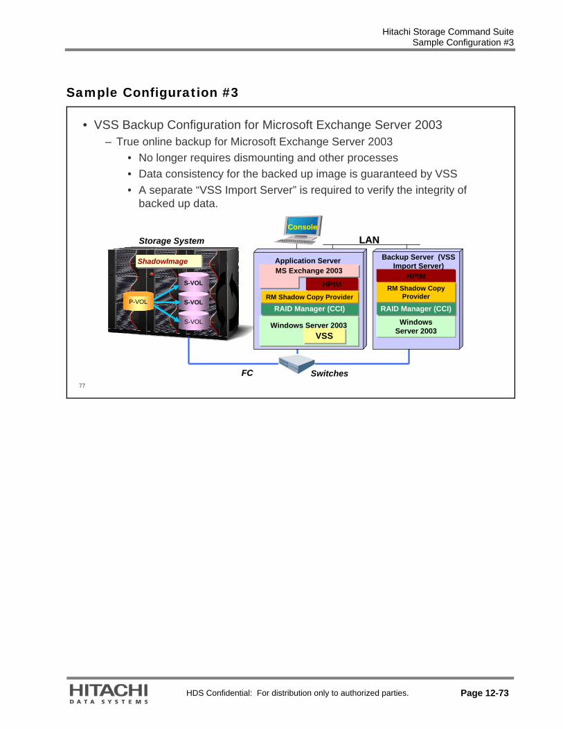
Hitachi Storage Command Suite Sample Configuration #3
HDS Confidential: For distribution only to authorized parties. Page 12-73
Sample Configuration #3
77
• VSS Backup Configuration for Microsoft Exchange Server 2003– True online backup for Microsoft Exchange Server 2003
• No longer requires dismounting and other processes• Data consistency for the backed up image is guaranteed by VSS• A separate “VSS Import Server” is required to verify the integrity of
backed up data.
Storage System
ShadowImageShadowImage
S-VOL
S-VOL
S-VOL
P-VOL
FCFC Switches
Console
LANLAN
Windows Server 2003
HPtM
Backup Server (VSS Import Server)
RAID Manager (CCI)RAID Manager (CCI)
RM Shadow Copy Provider
RM Shadow Copy Provider
MS Exchange 2003MS Exchange 2003
HPtMHPtM
Application Server
RAID Manager (CCI)RAID Manager (CCI)
VSSVSS
RM Shadow Copy ProviderRM Shadow Copy Provider
Windows Server 2003

Hitachi Storage Command Suite Sample Configuration #4
Page 12-74 HDS Confidential: For distribution only to authorized parties.
Sample Configuration #4
78
• Tape Integration – What To Do:– Export, transfer, and import the backup catalog– Mount the target secondary volumes (S-VOLs) to the back up server – Let the backup software transport the data in the S-VOL to the tape – Unmount the mounted S-VOLs upon completion
ConsoleLANLAN
FC Switches
Tape LibraryStorage System
S-VOL
ShadowImage* and/orCopy-on-Write softwareShadowImage* and/orCopy-on-Write software
P-Vol
P-Vol
P-Vol
Windows Server 2003
MS Exchange or SQLMS Exchange or SQL
HPtMHPtM
Application Server
RAID Manager (CCI)RAID Manager (CCI)
Backup SoftwareBackup Server
RAID Manager (CCI)RAID Manager (CCI)
HPtM
Windows Server 2003
S-VOL
S-VOL
S-VOL
*ShadowImage Replication software
In the diagram and following pages:
HPtM is Hitachi Protection Manager software

Hitachi Storage Command Suite Storage Services Manager Software
HDS Confidential: For distribution only to authorized parties. Page 12-75
Storage Services Manager Software
79
Business ApplicationModules
Storage OperationsModules
Basic Operating System
Hitachi Storage Specific HeterogeneousHeterogeneous
Device Manager
API – CIM/SMI-S Provisioning Configuration Replication Configuration
Resource ManagerVirtual Partition
ManagerServer Priority
Manager
QoS Application ModulesQoS Application ModulesOracle Oracle -- Exchange Exchange -- Sybase Sybase --SQL Server SQL Server –– NetApp OptionNetApp Option
QoS for QoS for File ServersFile Servers
SRMSRM
ChargebackChargeback PathPathProvisioningProvisioning Global Global
ReporterReporter
Storage Services Manager Storage Services Manager
Backup Backup Services Services ManagerManager
Tiered Storage Manager
Replication Monitor
Tuning Manager
Dynamic Link ManagerDynamic Link ManagerPath failover and failback load balancingPath failover and failback load balancing
Global Link ManagerGlobal Link Manager Protection Manager
Exchange - SQL Server
Reporting
Universal Volume Manager
Performance Monitor

Hitachi Storage Command Suite Storage Services Manager Software
Page 12-76 HDS Confidential: For distribution only to authorized parties.
80
• True Heterogeneous Management– Standards-based platform
• (CIM and SMI-S)– Heterogeneous storage management– Auto-discovery and topology
rendering– Real-time application-based
monitoring and reporting– Role-based management and
security– Risk analysis– Web-based GUI, CLI, and rapid
application development environment
Heterogeneous Storage Management—
Storage Service Manager software has encapsulated a list of daily IT device management tasks that can be performed consistently across heterogeneous environments. These include event management, performance monitoring and others. This abstraction dramatically increases the productivity and improves the organization’s ability to scale.
Auto Discovery and Topology Rendering—
Storage Services Manager software automatically discovers your SAN infrastructure and renders both the physical and logical topology. This view is ideally suited to empower your Infrastructure Administrators with instant visualization of your resources. The Storage Services Manager software provides a unique visualization ability to zoom in and out all the way from the application’s perspective down to the device details. This navigation of contextual information is vital to correlate the individual actions to the entire environment.
Real Time Monitoring and Reporting—
Today’s IT organizations are being forced by business requirements to provide real time support. The Storage Services Manager software gives you the capability to look at your infrastructure performance in real time, all the way from an application down to the storage system. Each type of supported equipment has multiple

Hitachi Storage Command Suite Storage Services Manager Software
HDS Confidential: For distribution only to authorized parties. Page 12-77
predefined performance views to provide real time performance information and monitoring capabilities.
Role-based Management and Security—
Storage Services Manager software incorporates a customizable, easy to use and robust role-based security mechanism that allows an organization to manage the infrastructure consistent with the individual roles in an organization. Users can tailor not only the level of control that they can manage but also the scope of action. Storage Services Manager software’s security model makes it possible for the executive management to view reports only; operations personnel to have read-only access to event management; and principal SAN engineers to provision and reconfigure elements within the infrastructure. It provides the flexibility to members with different organizational roles to manage infrastructure.
Risk Analysis —
Storage Services Manager software identifies areas of risk including any single points of failure in your environment, host bus adaptor (HBA) firmware versions that have a known problem, and the most business critical equipment in your inventory that should be properly protected. These reports can be generated on a daily basis or as a policy action. It identifies single points of failure to mitigate the risk of potential downtime.
Web-based GUI, CLI and rapid application development environment—
Storage Services Manager software’s rapid application development environment is a rich set of CLIs, APIs, and ODBC/JDBC database interfaces that enables Storage Authority end-users and OEM partners to write their own Advisors and Automators and add their own unique value to the platform for further differentiation, IP creation and to create and customize their own internal storage utility.
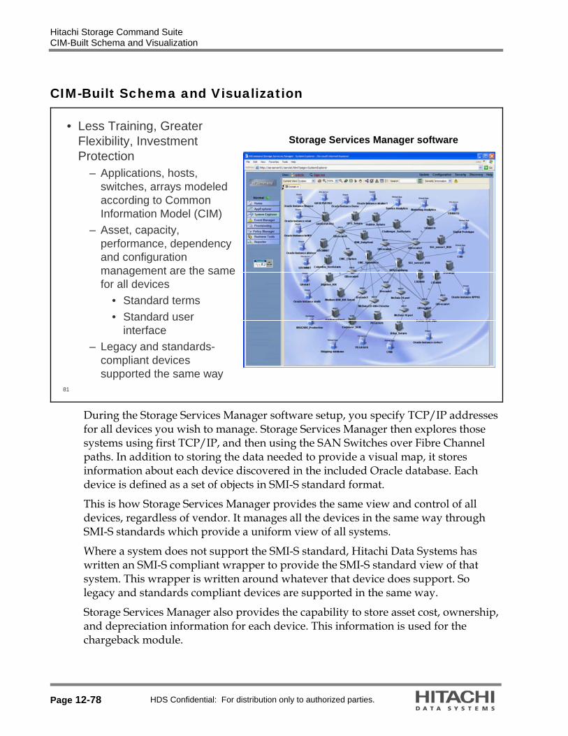
Hitachi Storage Command Suite CIM-Built Schema and Visualization
Page 12-78 HDS Confidential: For distribution only to authorized parties.
CIM-Built Schema and Visualization
81
• Less Training, Greater Flexibility, Investment Protection
– Applications, hosts, switches, arrays modeled according to Common Information Model (CIM)
– Asset, capacity, performance, dependency and configuration management are the same for all devices
• Standard terms• Standard user
interface– Legacy and standards-
compliant devices supported the same way
Storage Services Manager software
During the Storage Services Manager software setup, you specify TCP/IP addresses for all devices you wish to manage. Storage Services Manager then explores those systems using first TCP/IP, and then using the SAN Switches over Fibre Channel paths. In addition to storing the data needed to provide a visual map, it stores information about each device discovered in the included Oracle database. Each device is defined as a set of objects in SMI-S standard format.
This is how Storage Services Manager provides the same view and control of all devices, regardless of vendor. It manages all the devices in the same way through SMI-S standards which provide a uniform view of all systems.
Where a system does not support the SMI-S standard, Hitachi Data Systems has written an SMI-S compliant wrapper to provide the SMI-S standard view of that system. This wrapper is written around whatever that device does support. So legacy and standards compliant devices are supported in the same way.
Storage Services Manager also provides the capability to store asset cost, ownership, and depreciation information for each device. This information is used for the chargeback module.

Hitachi Storage Command Suite Why Storage Services Manager?
HDS Confidential: For distribution only to authorized parties. Page 12-79
Why Storage Services Manager?
82
Does your company use one of these advanced methods of storage management?

Hitachi Storage Command Suite Why Storage Services Manager?
Page 12-80 HDS Confidential: For distribution only to authorized parties.
83
• With increasingly complex storage architectures, what must organizations do?
– Reduce the number of point tools used for storage management
– Manage increasing capacity and complexity without increasing head count
– Find software that lets the organization treat storage as a “utility”
– Choose storage management infrastructure software before choosing its next storage system
• Bottom Line: Find an easier, application-centric way to manage the entire infrastructure that delivers clear value to the business
1. More Data
2. More Storage
3. More SANElements
4. More Element Managers
5. More Staff Management Tools
Spiraling Cost and Complexity
Storage Services Manager software is designed to help customers reduce the complexity of their complicated heterogeneous environment; for the different storage arrays, switches, HBAs, servers, volume management and pathing software, firmware levels, and perhaps most important the applications that serve them. Most of the first generation management tools require customers to install multiple tools. For instance, other manufacturers offers six or seven (at the last count) to do what can be accomplished in a single Storage Services Manager product. Many other first generation systems require the installation and on-going maintenance of heavy agents. Storage Services Manager is the first independent management platform that offers a comprehensive simple solution to these problems. No other product focuses above the device level to understand the true relationship with the applications served by the storage infrastructure. Storage Services Manager makes it easy to work toward the storage utility vision.
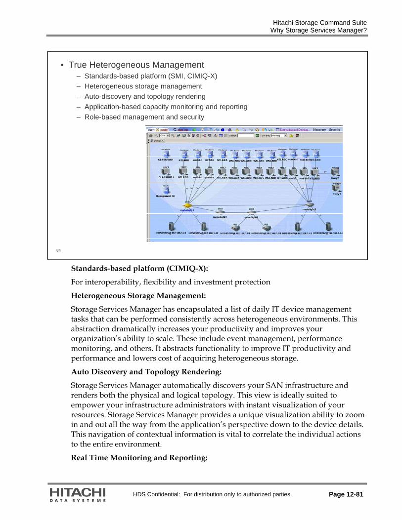
Hitachi Storage Command Suite Why Storage Services Manager?
HDS Confidential: For distribution only to authorized parties. Page 12-81
84
• True Heterogeneous Management– Standards-based platform (SMI, CIMIQ-X)– Heterogeneous storage management– Auto-discovery and topology rendering– Application-based capacity monitoring and reporting– Role-based management and security
Standards-based platform (CIMIQ-X):
For interoperability, flexibility and investment protection
Heterogeneous Storage Management:
Storage Services Manager has encapsulated a list of daily IT device management tasks that can be performed consistently across heterogeneous environments. This abstraction dramatically increases your productivity and improves your organization’s ability to scale. These include event management, performance monitoring, and others. It abstracts functionality to improve IT productivity and performance and lowers cost of acquiring heterogeneous storage.
Auto Discovery and Topology Rendering:
Storage Services Manager automatically discovers your SAN infrastructure and renders both the physical and logical topology. This view is ideally suited to empower your infrastructure administrators with instant visualization of your resources. Storage Services Manager provides a unique visualization ability to zoom in and out all the way from the application’s perspective down to the device details. This navigation of contextual information is vital to correlate the individual actions to the entire environment.
Real Time Monitoring and Reporting:

Hitachi Storage Command Suite Why Storage Services Manager?
Page 12-82 HDS Confidential: For distribution only to authorized parties.
Today’s IT organizations are being forced by business requirements to provide real time support. Storage Services Manager gives you the capability to look at your infrastructure performance in real time, all the way from an application down to the storage system. Each type of supported equipment has multiple predefined performance views to provide real time performance information and monitoring capabilities.
Role-based Management and Security:
Storage Services Manager incorporates a customizable, easy to use and robust role-based security mechanism that allows an organization to manage the infrastructure in a manner that is consistent with the individual roles in an organization. Users can tailor not only the level of control that they can manage but also the scope of action. The security model makes it possible for the executive management to view reports only; operations personnel to have read-only access to event management; and principal SAN engineers to provision and reconfigure elements within the infrastructure. It provides flexibility of members with different organizational roles to manage infrastructure.
Risk Analysis:
Storage Services Manager identifies areas of risk including any single points of failure in your environment, HBA firmware versions that have a known problem, and the most business critical equipment in your inventory that should be properly protected. These reports can be generated on a daily basis or as a policy action. It identifies single points of failure to mitigate the risk of potential downtime.
Web-based GUI, CLI and Rapid Application Development Environment:
The Storage Services Manager environment has a rich set of CLIs and APIs that enables Storage Services Manager end-users and OEM partners to write their own Advisors and Automators and add their own unique value to the platform for further differentiation and to create and customize their own internal storage utility.
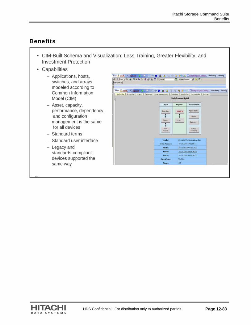
Hitachi Storage Command Suite Benefits
HDS Confidential: For distribution only to authorized parties. Page 12-83
Benefits
85
• CIM-Built Schema and Visualization: Less Training, Greater Flexibility, and Investment Protection
• Capabilities– Applications, hosts,
switches, and arrays modeled according to Common Information Model (CIM)
– Asset, capacity, performance, dependency,and configuration
management is the samefor all devices
– Standard terms– Standard user interface– Legacy and
standards-compliant devices supported the same way

Hitachi Storage Command Suite Benefits
Page 12-84 HDS Confidential: For distribution only to authorized parties.
86
• System-wide capacity management maximizes utilization, ensures availability• Capabilities
– System-wide capacity view identifies• Excess capacity• Under-used
resources• At-risk resources• Candidates for
consolidation– Capacity presented
“in context” for each layer in storage stack
• Application• Host• Switch• Subsystem
– Trending and extrapolationfor accurate forecasting
• Performance Explorer• Capabilities
– Provides a graphical representation of the performance history of a managed element
– Manipulate charts so they show a different reporting period and frequency

Hitachi Storage Command Suite Management Server Maintenance Features
HDS Confidential: For distribution only to authorized parties. Page 12-85
Management Server Maintenance Features
88
• Product Health Monitoring is all about the management server monitoring itself:
– Storage used for Oracle database elements– Log file management – RMAN backup scheduling and backup status
• An agent is installed on localhost when the management server isinstalled
• Monitoring product health collects data for localhost only• An application license and separate installation is required to monitor
Oracle applications other than the management server
The product health statistics monitored by the management server are:
Disk capacity Free space Total storage used by Database files (.LOG, .DBF, and .CTL) Total storage used by .ARC files Total storage used by RMAN backup directories and files Total storage used by Temporary Tablespace
User specified schedules control the Data collection for these statistics

Hitachi Storage Command Suite Management Server Maintenance Features
Page 12-86 HDS Confidential: For distribution only to authorized parties.
89
• Log Management UI– User action audit log, log detail level settings, log, and DB downloads with
stripped report cache option

Hitachi Storage Command Suite Features
HDS Confidential: For distribution only to authorized parties. Page 12-87
Features
90
• CIM Extension Management Tool (Deploy and Upgrade)• CIM Extension (CXWS Agent Framework) for Windows• Migration from Oracle DB Ent. Edition to Std. Edition• System Task Dashboard• Java Launcher (processes now have descriptive names)• Uses Java v1.5• Topology Export to Microsoft Visio (XML)• TNS Listener Passwords (Oracle Security)• Troubleshooting mode debug screens• Firefox Browser Support• Topology Recalculation Optimization (Physical/Logical Topology Paths
updated dynamically – At startup, after GAED, deletion, or provisioning)• GUI Performance via cache management and pagination

Hitachi Storage Command Suite Operating System, Multipath, Volume Manager, and File System
Page 12-88 HDS Confidential: For distribution only to authorized parties.
Operating System, Multipath, Volume Manager, and File System
91
• Microsoft Storport Drivers for Microsoft Windows (Emulex and QLogic)• MPIO for EVA on Microsoft Windows 2000 and 2003• MPIO for XP12000 on Microsoft Windows 2003• Windows IA64 and x64• 64bit LINUX (SuSE and RedHat, AMD, and Itanium)• RHEL 4.0• VxVM 4.1 on Microsoft Windows, Linux, Sun Solaris• Veritas on LINUX (VxVM, DMP, VxFS)• OVMS 8.2-1 support (Itanium Only)

Hitachi Storage Command Suite Switch and Storage Arrays
HDS Confidential: For distribution only to authorized parties. Page 12-89
Switch and Storage Arrays
92
• Switch and Switch Software– Brocade SMI-S Provider Support– HP San Switch 4/8, 4/16 (Brocade Silkworm 200E)– McData 4GB SAN Switch for HP p-Class Blade System– Cisco MDS 9020
• Storage Array and Array Software– Network Storage Controller, Universal Storage Platform, Universal Storage
Platform V/ VM, XP LPAR– Device Manager v4.2 or later– CommandView EVA v5.0x with SMI-S v5.01 patch– CommandView XP 2.2B support using SMI-S Provider– IBM® DS6800, DS8100, DS8300– Sun 6540 and 6140 (Engenio 6998 and 3992)

Hitachi Storage Command Suite Tape, HBA, NAS, and Application Support
Page 12-90 HDS Confidential: For distribution only to authorized parties.
Tape, HBA, NAS, and Application Support
93
• HBA Support– Emulex PCI-X and PCIe 4Gb– QLogic PCI-X 4Gb
• NAS Support– HP NAS on Linux– SUN StorageTek NAS 5210, 5310, 5320
• Application Support– Microsoft Exchange 2003 SP2– Microsoft SQL 2000 on Itanium (IA64) Windows– Oracle10g on Tru64 Clusters

Hitachi Storage Command Suite Policy Manager Features
HDS Confidential: For distribution only to authorized parties. Page 12-91
Policy Manager Features
94
• Capacity Trending Policies– Based on daily rollup– Minimum of seven samples
• NAS Policies– Notified when aggregate is x% used– Notified when volume is x% of allocation used
• FSRM Policies– File server user percent used
Percent of storage used for each file server user

Hitachi Storage Command Suite Chargeback Manager
Page 12-92 HDS Confidential: For distribution only to authorized parties.
Chargeback Manager
95
• Chargeback Manager– Storage Volume Level Chargeback– NAS Utilization Chargeback– Enables up to 64 storage tiers (previously 3)– Allows subsystems to have volumes or storage groups that reside in multiple
tiers.• Default chargeback method will now be storage-based, from Chargeback
Ownership screen– Previous versions, default was asset-based
• Can now define each tier– Name– Cost per GB per month

Hitachi Storage Command Suite Path Provisioning Features
HDS Confidential: For distribution only to authorized parties. Page 12-93
Path Provisioning Features
96
• Path Provisioning – Security– User-definable templates to restrict users by role:
• Template has settings for customization and filtering parameters• End user can save their own template

Hitachi Storage Command Suite CIM Extension Features
Page 12-94 HDS Confidential: For distribution only to authorized parties.
CIM Extension Features
97
• CIM Extension Default User – Cxws.default.login read at installation (custom install media or deploy tool)
providing a user-definable uname:pwordCREDENTIALS <uname>:<pword>
– This populates the “cim.extension.parameters” read by the agent at startup. (was cxws.host.parameters in earlier versions)
– Supports HP-UX, Microsoft Windows, Linux, Sun Solaris, and AIX

Hitachi Storage Command Suite System Task Manager Dashboard
HDS Confidential: For distribution only to authorized parties. Page 12-95
System Task Manager Dashboard
98

Hitachi Storage Command Suite Report Handling/Processing
Page 12-96 HDS Confidential: For distribution only to authorized parties.
Report Handling/Processing
99
• General Reporting Features– Disable Report Cache update during GAED– Report parameterization – Provides user ability to filter reports using user-
defined or system-defined parameters– Materialized view refresh now queued until GAED completed. (no more empty
reports)• NetApp NAS Reports
– Volume Report (shows volumes that are running out of disk space)– Quota Reports (shows filers approaching their top capacity)– Shares Reports (shares, type, mount point, hosts for the Filer’s share)– Aggregate Report (resource usage and those close to running out of disk
space)– Snapshot report (shows volumes whose snapshots are about to run out of
reserved snapshot space)• File SRM Report
– “Stale Files” summary (files whose access time exceeds 180 days)

Hitachi Storage Command Suite FSRM Setup in Config Page
HDS Confidential: For distribution only to authorized parties. Page 12-97
FSRM Setup in Config Page
100

Hitachi Storage Command Suite
Page 12-98 HDS Confidential: For distribution only to authorized parties.

HDS Confidential: For distribution only to authorized parties. Page 1
Glossary
Click a letter below to jump to that letter’s terms in the glossary.
A B C D E F G H I J K L M N O P Q R S T U V W X Y Z
—A— ACC— Action Code. A SIM System Information
Message. Will produce an ACC which takes an engineer to the correct fix procedures in the ACC directory in the MM (Maintenance Manual)
ACE (Access Control Entry) — Stores access rights for a single user or group within the Windows security model
ACL (Access Control List)— stores a set of ACEs, so describes the complete set of access rights for a file system object within the Microsoft Windows security model
ACP (Array Control Processor) ― Microprocessor mounted on the disk adapter circuit board (DKA) that controls the drives in a specific disk array. Considered part of the back-end, it controls data transfer between cache and the hard drives.
ACP PAIR ― Physical disk access control logic. Each ACP consists of two DKA PCBs. To provide 8 loop paths to the real HDDs
Actuator (arm) — read/write heads are attached to a single head actuator, or actuator arm, that moves the heads around the platters
AD — Active Directory ADC — Accelerated Data Copy ADP —Adapter ADS — Active Directory Service Address— A location of data, usually in main
memory or on a disk. A name or token that identifies a network component. In local area networks (LANs), for example, every node has a unique address
AIX — IBM UNIX
AL (Arbitrated Loop) — A network in which nodes contend to send data and only one node at a time is able to send data.
AL-PA — Arbitrated Loop Physical Address AMS —Adaptable Modular Storage APID — An ID to identify a command device. APF (Authorized Program Facility) — In z/OS and
OS/390 environments, a facility that permits the identification of programs that are authorized to use restricted functions.
Application Management —The processes that manage the capacity and performance of applications
ARB — Arbitration or “request” Array Domain—all functions, paths, and disk
drives controlled by a single ACP pair. An array domain can contain a variety of LVI and/or LU configurations.
ARRAY UNIT - A group of Hard Disk Drives in one RAID structure. Same as Parity Group
ASIC — Application specific integrated circuit ASSY — Assembly Asymmetric virtualization — See Out-of-band
virtualization. Asynchronous— An I/O operation whose initiator
does not await its completion before proceeding with other work. Asynchronous I/O operations enable an initiator to have multiple concurrent I/O operations in progress.
ATA — Short for Advanced Technology Attachment, a disk drive implementation that integrates the controller on the disk drive itself, also known as IDE (Integrated Drive Electronics) Advanced Technology Attachment is a standard designed to connect hard and removable disk drives

HDS Confidential: For distribution only to authorized parties. Page 2
Authentication — The process of identifying an individual, usually based on a username and password.
Availability — Consistent direct access to information over time
-back to top-
—B— B4 — A group of 4 HDU boxes that are used to
contain 128 HDDs Backend— In client/server applications, the client
part of the program is often called the front-end and the server part is called the back-end. Backup image—Data saved during an archive operation. It includes all the associated files, directories, and catalog information of the backup operation.
BATCTR — Battery Control PCB BED — Back End Director. Controls the paths to
the HDDs Bind Mode — One of two modes available when
using FlashAccess™, in which the FlashAccess™ extents hold read data for specific extents on volumes (see Priority Mode).
BST — Binary Search Tree BTU— British Thermal Unit Business Continuity Plan — Describes how an
organization will resume partially- or completely interrupted critical functions within a predetermined time after a disruption or a disaster. Sometimes also called a Disaster Recovery Plan.
-back to top-
—C— CA — Continuous Access software (see HORC) Cache — Cache Memory. Intermediate buffer
between the channels and drives. It has a maximum of 64 GB (32 GB x 2 areas) of capacity. It is available and controlled as two areas of cache (cache A and cache B). It is fully battery-backed (48 hours) .
Cache hit rate — When data is found in the cache, it is called a cache hit, and the effectiveness of a cache is judged by its hit rate.
Cache partitioning — Storage management software that allows the virtual partitioning of cache and allocation of it to different applications
CAD — Computer-Aided Design Capacity — Capacity is the amount of data that a
drive can store after formatting. Most data storage companies, including HDS, calculate capacity based on the assumption that 1 megabyte = 1000 kilobytes and 1 gigabyte=1,000 megabytes.
CAPEX - capital expenditure - is the cost of developing or providing non-consumable parts for the product or system. For example, the purchase of a photocopier is the CAPEX, and the annual paper and toner cost is the OPEX. (See OPEX).
CAS — Column address strobe is a signal sent to a dynamic random access memory (DRAM) that tells it that an associated address is a column address. CAS- column address strobe sent by the processor to a DRAM circuit to activate a column address.
CCI — Command Control Interface CE — Customer Engineer Centralized management —Storage data
management, capacity management, access security management, and path management functions accomplished by software.
CentOS — Community Enterprise Operating System
CFW— Cache Fast Write CHA (Channel Adapter) ― Provides the channel
interface control functions and internal cache data transfer functions. It is used to convert the data format between CKD and FBA. The CHA contains an internal processor and 128 bytes of edit buffer memory.
CH — Channel CHA — Channel Adapter CHAP — Challenge-Handshake Authentication
Protocol CHF — Channel Fibre CHIP (Client-Host Interface Processor) ―
Microprocessors on the CHA boards that process the channel commands from the hosts and manage host access to cache.
CHK— Check CHN — CHannel adapter NAS CHP — Channel Processor or Channel Path CHPID — Channel Path Identifier CH S— Channel SCSI CHSN — Cache memory Hierarchical Star
Network
HDS Confidential: For distribution only to authorized parties. Page 3
CHT—Channel tachyon, a Fibre Channel protocol controller
CIFS protocol — common internet file system is a platform-independent file sharing system. A network file system access protocol primarily used by Windows clients to communicate file access requests to Windows servers.
CIM — Common Information ModelCKD (Count-key Data) ― A format for encoding data on hard disk drives; typically used in the mainframe environment.
CKPT — Check Point CL — See Cluster CLI — Command Line Interface CLPR (Cache Logical PaRtition) — Cache can be
divided into multiple virtual cache memories to lessen I/O contention.
Cluster — A collection of computers that are interconnected (typically at high-speeds) for the purpose of improving reliability, availability, serviceability and/or performance (via load balancing). Often, clustered computers have access to a common pool of storage, and run special software to coordinate the component computers' activities.
CM (Cache Memory Module) ― Cache Memory. Intermediate buffer between the channels and drives. It has a maximum of 64 GB (32 GB x 2 areas) of capacity. It is available and controlled as two areas of cache (cache A and cache B). It is fully battery-backed (48 hours)
CM PATH (Cache Memory Access Path) ― Access Path from the processors of CHA, DKA PCB to Cache Memory.
CMD — Command CMG — Cache Memory Group CNAME — Canonical NAME CPM (Cache Partition Manager) — Allows for
partitioning of the cache and assigns a partition to a LU; this enables tuning of the system’s performance.
CNS— Clustered Name Space Concatenation — A logical joining of two series of
data. Usually represented by the symbol “|”. In data communications, two or more data are often concatenated to provide a unique name or reference (e.g., S_ID | X_ID). Volume managers concatenate disk address spaces to present a single larger address spaces.
Connectivity technology — a program or device's ability to link with other programs and devices. Connectivity technology allows programs on a given computer to run routines or access objects on another remote computer
Controller — A device that controls the transfer of data from a computer to a peripheral device (including a storage system) and vice versa.
Controller-based Virtualization — Driven by the physical controller at the hardware microcode level versus at the application software layer and integrates into the infrastructure to allow virtualization across heterogeneous storage and third party products
Corporate governance — Organizational compliance with government-mandated regulations
COW — Copy On Write Snapshot CPS — Cache Port Slave CPU — Central Processor Unit CRM — Customer Relationship Management CruiseControl — Now called Hitachi Volume
Migration software CSV — Comma Separated Value CSW (Cache Switch PCB) ― The cache switch
(CSW) connects the channel adapter or disk adapter to the cache. Each of them is connected to the cache by the Cache Memory Hierarchical Star Net (C-HSN) method. Each cluster is provided with the two CSWs, and each CSW can connect four caches. The CSW switches any of the cache paths to which the channel adapter or disk adapter is to be connected through arbitration.
CU (Control Unit) — The hexadecimal number to which 256 LDEVs may be assigned
CUDG —Control Unit DiaGnostics. Internal system tests.
CV — Custom Volume CVS (Customizable Volume Size) ― software
used to create custom volume sizes. Marketed under the name Virtual LVI (VLVI) and Virtual LUN (VLUN)
-back to top-
—D— DAD (Device Address Domain) — Indicates a site
of the same device number automation

HDS Confidential: For distribution only to authorized parties. Page 4
support function. If several hosts on the same site have the same device number system, they have the same name.
DACL — Discretionary ACL - the part of a security descriptor that stores access rights for users and groups.
DAMP (Disk Array Management Program) ― Renamed to Storage Navigator Modular (SNM)
DAS — Direct Attached Storage DASD—Direct Access Storage Device Data Blocks — A fixed-size unit of data that is
transferred together. For example, the X-modem protocol transfers blocks of 128 bytes. In general, the larger the block size, the faster the data transfer rate.
Data Integrity —Assurance that information will be protected from modification and corruption.
Data Lifecycle Management — An approach to information and storage management. The policies, processes, practices, services and tools used to align the business value of data with the most appropriate and cost-effective storage infrastructure from the time data is created through its final disposition. Data is aligned with business requirements through management policies and service levels associated with performance, availability, recoverability, cost and what ever parameters the organization defines as critical to its operations.
Data Migration— The process of moving data from one storage device to another. In this context, data migration is the same as Hierarchical Storage Management (HSM).
Data Pool— A volume containing differential data only.
Data Striping — Disk array data mapping technique in which fixed-length sequences of virtual disk data addresses are mapped to sequences of member disk addresses in a regular rotating pattern.
Data Transfer Rate (DTR) — The speed at which data can be transferred. Measured in kilobytes per second for a CD-ROM drive, in bits per second for a modem, and in megabytes per second for a hard drive. Also, often called simply data rate.
DCR (Dynamic Cache Residency) ― see FlashAccess™
DE— Data Exchange Software Device Management — Processes that configure
and manage storage systems
DDL — Database Definition Language DDNS —Dynamic DNS DFS — Microsoft Distributed File System DFW —DASD Fast Write DIMM—Dual In-line Memory Module Direct Attached Storage — Storage that is directly
attached to the application or file server. No other device on the network can access the stored data
Director class switches — larger switches often used as the core of large switched fabrics
Disaster Recovery Plan (DRP) — A plan that describes how an organization will deal with potential disasters. It may include the precautions taken to either maintain or quickly resume mission-critical functions. Sometimes also referred to as a Business Continuity Plan.
Disk Administrator — An administrative tool that displays the actual LU storage configuration
Disk Array — A linked group of one or more physical independent hard disk drives generally used to replace larger, single disk drive systems. The most common disk arrays are in daisy chain configuration or implement RAID (Redundant Array of Independent Disks) technology. A disk array may contain several disk drive trays, and is structured to improve speed and increase protection against loss of data. Disk arrays organize their data storage into Logical Units (LUs), which appear as linear block paces to their clients. A small disk array, with a few disks, might support up to 8 LUs; a large one, with hundreds of disk drives, can support thousands.
DKA (Disk Adapter) ― Also called an array control processor (ACP); it provides the control functions for data transfer between drives and cache. The DKA contains DRR (Data Recover and Reconstruct), a parity generator circuit. It supports four fibre channel paths and offers 32 KB of buffer for each fibre channel path.
DKC (Disk Controller Unit) ― In a multi-frame configuration, the frame that contains the front end (control and memory components).
DKCMN ― Disk Controller Monitor. Monitors temperature and power status throughout the machine
DKF (fibre disk adapter) ― Another term for a DKA.DKU (Disk Unit) ― In a multi-frame

HDS Confidential: For distribution only to authorized parties. Page 5
configuration, a frame that contains hard disk units (HDUs).
DLIBs — Distribution Libraries DLM —Data Lifecycle Management DMA— Direct Memory Access DM-LU (Differential Management Logical Unit) —
DM-LU is used for saving management information of the copy functions in the cache
DMP — Disk Master Program DNS — Domain Name System Domain — A number of related storage array
groups. An “ACP Domain” or “Array Domain” means all of the array-groups controlled by the same pair of DKA boards. OR ― The HDDs managed by one ACP PAIR (also called BED)
DR — Disaster Recovery DRR (Data Recover and Reconstruct) —Data
Parity Generator chip on DKA DRV — Dynamic Reallocation Volume DSB — Dynamic Super Block DSP — Disk Slave Program DTA —Data adapter and path to cache-switches DW — Duplex Write DWL — Duplex Write Line Dynamic Link Manager — HDS software that
ensures that no single path becomes overworked while others remain underused. Dynamic Link Manager does this by providing automatic load balancing, path failover, and recovery capabilities in case of a path failure.
-back to top-
—E— ECC — Error Checking & Correction ECC.DDR SDRAM — Error Correction Code
Double Data Rate Synchronous Dynamic RAm Memory
ECN — Engineering Change Notice E-COPY — Serverless or LAN free backup ENC — Stands for ENclosure Controller, the units
that connect the controllers in the DF700 with the Fibre Channel disks. They also allow for online extending a system by adding RKAs
ECM— Extended Control Memory EOF — End Of Field EPO — Emergency Power Off ENC — Enclosure EREP — Error REporting and Printing ERP — Enterprise Resource Management ESA — Enterprise Systems Architecture ESC — Error Source Code ESCD — ESCON Director ESCON (Enterprise Systems Connection) ― An
input/output (I/O) interface for mainframe computer connections to storage devices developed by IBM.
Ethernet — A local area network (LAN) architecture that supports clients and servers and uses twisted pair cables for connectivity.
EVS — Enterprise Virtual Serve ExSA — Extended Serial Adapter
-back to top-
—F— Fabric — The hardware that connects
workstations and servers to storage devices in a SAN is referred to as a "fabric." The SAN fabric enables any-server-to-any-storage device connectivity through the use of Fibre Channel switching technology.
Failback — The restoration of a failed system share of a load to a replacement component. For example, when a failed controller in a redundant configuration is replaced, the devices that were originally controlled by the failed controller are usually failed back to the replacement controller to restore the I/O balance, and to restore failure tolerance. Similarly, when a defective fan or power supply is replaced, its load, previously borne by a redundant component, can be failed back to the replacement part.
Failed over — A mode of operation for failure tolerant systems in which a component has failed and its function has been assumed by a redundant component. A system that protects against single failures operating in failed over mode is not failure tolerant, since failure of the redundant component may render the system unable to function. Some systems (e.g., clusters) are able to tolerate more than one failure; these remain failure tolerant until no redundant component is available to protect against further failures.

HDS Confidential: For distribution only to authorized parties. Page 6
Failover — A backup operation that automatically switches to a standby database server or network if the primary system fails, or is temporarily shut down for servicing. Failover is an important fault tolerance function of mission-critical systems that rely on constant accessibility. Failover automatically and transparently to the user redirects requests from the failed or down system to the backup system that mimics the operations of the primary system.
Failure tolerance — The ability of a system to continue to perform its function or at a reduced performance level, when one or more of its components has failed. Failure tolerance in disk subsystems is often achieved by including redundant instances of components whose failure would make the system inoperable, coupled with facilities that allow the redundant components to assume the function of failed ones.
FAIS — Fabric Application Interface Standard FAL — File Access Library FAT — File Allocation Table Fault Tolerat — Describes a computer system or
component designed so that, in the event of a component failure, a backup component or procedure can immediately take its place with no loss of service. Fault tolerance can be provided with software, embedded in hardware, or provided by some hybrid combination.
FBA — Fixed-block Architecture. Physical disk sector mapping.
FBA/CKD Conversion — The process of converting open-system data in FBA format to mainframe data in CKD format.
FBA — Fixed Block Architecture FBUS — Fast I/O Bus FC ― Fibre Channel is a technology for
transmitting data between computer devices; a set of standards for a serial I/O bus capable of transferring data between two ports
FC-0 ― Lowest layer on fibre channel transport, it represents the physical media.
FC-1 ― This layer contains the 8b/10b encoding scheme.
FC-2 ― This layer handles framing and protocol, frame format, sequence/exchange management and ordered set usage.
FC-3 ― This layer contains common services used by multiple N_Ports in a node.
FC-4 ― This layer handles standards and profiles for mapping upper level protocols like SCSI an IP onto the Fibre Channel Protocol.
FCA ― Fibre Adapter. Fibre interface card. Controls transmission of fibre packets.
FC-AL — Fibre Channel Arbitrated Loop. A serial data transfer architecture developed by a consortium of computer and mass storage device manufacturers and now being standardized by ANSI. FC-AL was designed for new mass storage devices and other peripheral devices that require very high bandwidth. Using optical fiber to connect devices, FC-AL supports full-duplex data transfer rates of 100MBps. FC-AL is compatible with SCSI for high-performance storage systems.
FC-P2P — Fibre Channel Point-to-Point FC-SW — Fibre Channel Switched FCC — Federal Communications Commission FC — Fibre Channel or Field-Change (microcode
update) FCIP –Fibre Channel over IP, a network
storage technology that combines the features of Fibre Channel and the Internet Protocol (IP) to connect distributed SANs over large distances. FCIP is considered a tunneling protocol, as it makes a transparent point-to-point connection between geographically separated SANs over IP networks. FCIP relies on TCP/IP services to establish connectivity between remote SANs over LANs, MANs, or WANs. An advantage of FCIP is that it can use TCP/IP as the transport while keeping Fibre Channel fabric services intact.
FCP — Fibre Channel Protocol FC RKAJ (Fibre Channel Rack Additional) — Acronym referring to an additional rack unit(s) that houses additional hard drives exceeding the capacity of the core RK unit of the Thunder 9500V/9200 subsystem. FCU— File Conversion Utility FD — Floppy Disk FDR— Fast Dump/Restore FE — Field Engineer FED — Channel Front End Directors Fibre Channel — A serial data transfer
architecture developed by a consortium of computer and mass storage device manufacturers and now being standardized by ANSI. The most prominent Fibre Channel standard is Fibre Channel Arbitrated Loop (FC-AL).

HDS Confidential: For distribution only to authorized parties. Page 7
FICON (Fiber Connectivity) ― A high-speed input/output (I/O) interface for mainframe computer connections to storage devices. As part of IBM's S/390 server, FICON channels increase I/O capacity through the combination of a new architecture and faster physical link rates to make them up to eight times as efficient as ESCON (Enterprise System Connection), IBM's previous fiber optic channel standard.
Flash ACC ― Flash access. Placing an entire LUN into cache
FlashAccess — HDS software used to maintain certain types of data in cache to ensure quicker access to that data.
FLGFAN ― Front Logic Box Fan Assembly. FLOGIC Box ― Front Logic Box. FM (Flash Memory) — Each microprocessor has
FM. FM is non-volatile memory which contains microcode.
FOP — Fibre Optic Processor or fibre open FPC — Failure Parts Code or Fibre Channel
Protocol Chip FPGA — Field Programmable Gate Array Frames — An ordered vector of words that is the
basic unit of data transmission in a Fibre Channel network.
Front-end — In client/server applications, the client part of the program is often called the front end and the server part is called the back end.
FS — File System FSA — File System Module-A FSB — File System Module-B FSM — File System Module FSW (Fibre Channel Interface Switch PCB) ― A
board that provides the physical interface (cable connectors) between the ACP ports and the disks housed in a given disk drive.
FTP (File Transfer Protocol) ― A client-server protocol which allows a user on one computer to transfer files to and from another computer over a TCP/IP network
FWD — Fast Write Differential
-back to top-
—G— GARD — General Available Restricted Distribution GB — Gigabyte
GBIC — Gigabit Interface Converter GID — Group Identifier GID — Group Identifier within the Unix security
model GigE — Giga Bit Ethernet GLM — Gigabyte Link Module Global Cache — Cache memory is used on
demand by multiple applications, use changes dynamically as required for READ performance between hosts/applications/LUs.
Graph-Track™ — HDS software used to monitor the performance of the Hitachi storage subsystems. Graph-Track™ provides graphical displays, which give information on device usage and system performance.
GUI — Graphical User Interface
-back to top-
—H— H1F — Essentially the Floor Mounted disk rack
(also called Desk Side) equivalent of the RK. (See also: RK, RKA, and H2F).
H2F — Essentially the Floor Mounted disk rack (also called Desk Side) add-on equivalent similar to the RKA. There is a limitation of only one H2F that can be added to the core RK Floor Mounted unit. (See also: RK, RKA, and H1F).
HLU (Host Logical Unit) — A LU that the Operating System and the HDLM recognizes. Each HLU includes the devices that comprise the storage LU
H-LUN — Host Logical Unit Number (See LUN) HA — High Availability HBA — Host Bus Adapter—An HBA is an I/O
adapter that sits between the host computer's bus and the Fibre Channel loop and manages the transfer of information between the two channels. In order to minimize the impact on host processor performance, the host bus adapter performs many low-level interface functions automatically or with minimal processor involvement.
HDD (Hard Disk Drive) ― A spindle of hard disks that make up a hard drive, which is a unit of physical storage within a subsystem.
HD — Hard Disk HDS — Hitachi Data Systems

HDS Confidential: For distribution only to authorized parties. Page 8
HDU (Hard Disk Unit) ― A number of hard drives (HDDs) grouped together within a subsystem.
HDLM — Hitachi Dynamic Link Manager software Head — See read/write head Heterogeneous — The characteristic of containing
dissimilar elements. A common use of this word in information technology is to describe a product as able to contain or be part of a heterogeneous network," consisting of different manufacturers' products that can interoperate. Heterogeneous networks are made possible by standards-conforming hardware and software interfaces used in common by different products, thus allowing them to communicate with each other. The Internet itself is an example of a heterogeneous network.
HiRDB — Hitachi Relational Database HIS — High Speed Interconnect HiStar — Multiple point-to-point data paths to
cache Hi Track System — Automatic fault reporting
system. HIHSM — Hitachi Internal Hierarchy Storage
Management HMDE — Hitachi Multiplatform Data Exchange HMRC F — Hitachi Multiple Raid Coupling Feature HMRS — Hitachi Multiplatform Resource Sharing HODM — Hitachi Online Data Migration Homogeneous — Of the same or similar kind HOMRCF — Hitachi Open Multiple Raid Coupling
Feature; Shadow Image, marketing name for HOMRCF
HORC — Hitachi Open Remote Copy ― See TrueCopy
HORCM — Hitachi Open Raid Configuration Manager
Host — Also called a server. A Host is basically a central computer that processes end-user applications or requests.
Host LU — See HLU Host Storage Domains—Allows host pooling at the
LUN level and the priority access feature lets administrator set service levels for applications
HP — Hewlett-Packard Company HPC — High Performance Computing HRC — Hitachi Remote Copy ― See TrueCopy HSG — Host Security Group
HSM — Hierarchical Storage Management HSSDC — High Speed Serial Data Connector HTTP — Hyper Text Transfer Protocol HTTPS — Hyper Text Transfer Protocol Secure Hub — A common connection point for devices in
a network. Hubs are commonly used to connect segments of a LAN. A hub contains multiple ports. When a packet arrives at one port, it is copied to the other ports so that all segments of the LAN can see all packets. A switching hub actually reads the destination address of each packet and then forwards the packet to the correct port.
HXRC — Hitachi Extended Remote Copy Hub — Device to which nodes on a multi-point bus
or loop are physically connected
-back to top-
—I— IBR — Incremental Block-level Replication IBR —Intelligent Block Replication ID — Identifier IDR — Incremental Data Replication iFCP — Short for the Internet Fibre Channel
Protocol, iFCP allows an organization to extend Fibre Channel storage networks over the Internet by using TCP/IP. TCP is responsible for managing congestion control as well as error detection and recovery services. iFCP allows an organization to create an IP SAN fabric that minimizes the Fibre Channel fabric component and maximizes use of the company's TCP/IP infrastructure.
In-band virtualization — Refers to the location of the storage network path, between the application host servers in the storage systems. Provides both control and data along the same connection path. Also called symmetric virtualization.
Interface —The physical and logical arrangement supporting the attachment of any device to a connector or to another device.
Internal bus — Another name for an internal data bus. Also, an expansion bus is often referred to as an internal bus.
Internal data bus — A bus that operates only within the internal circuitry of the CPU, communicating among the internal caches of memory that are part of the CPU chip’s design. This bus is typically rather quick and

HDS Confidential: For distribution only to authorized parties. Page 9
is independent of the rest of the computer’s operations.
IID — Stands for Initiator ID. This is used to identify LU whether it is NAS System LU or User LU. If it is 0, that means NAS System LU and if it is 1, then the LU is User LU.
IIS — Internet Information Server I/O — Input/Output — The term I/O (pronounced
"eye-oh") is used to describe any program, operation or device that transfers data to or from a computer and to or from a peripheral device.
IML — Initial Microprogram Load IP — Internet Protocol IPL — Initial Program Load IPSEC — IP security iSCSI (Internet SCSI ) — Pronounced eye skuzzy.
Short for Internet SCSI, an IP-based standard for linking data storage devices over a network and transferring data by carrying SCSI commands over IP networks. iSCSI supports a Gigabit Ethernet interface at the physical layer, which allows systems supporting iSCSI interfaces to connect directly to standard Gigabit Ethernet switches and/or IP routers. When an operating system receives a request it generates the SCSI command and then sends an IP packet over an Ethernet connection. At the receiving end, the SCSI commands are separated from the request, and the SCSI commands and data are sent to the SCSI controller and then to the SCSI storage device. iSCSI will also return a response to the request using the same protocol. iSCSI is important to SAN technology because it enables a SAN to be deployed in a LAN, WAN or MAN.
iSER — iSCSI Extensions for RDMA ISL — Inter-Switch Link iSNS — Internet Storage Name Service ISPF — Interactive System Productivity Facility ISC — Initial shipping condition ISOE — iSCSI Offload Engine ISP — Internet service provider
-back to top-
—J— Java (and Java applications). — Java is a widely
accepted, open systems programming
language. Hitachi’s enterprise software products are all accessed using Java applications. This enables storage administrators to access the Hitachi enterprise software products from any PC or workstation that runs a supported thin-client internet browser application and that has TCP/IP network access to the computer on which the software product runs.
Java VM — Java Virtual Machine JCL — Job Control Language JBOD — Just a Bunch of Disks JRE —Java Runtime Environment JMP —Jumper. Option setting method
-back to top-
—K— kVA— Kilovolt Ampere kW — Kilowatt
-back to top-
—L— LACP — Link Aggregation Control Protocol LAG — Link Aggregation Groups LAN— Local Area Network LBA (logical block address) — A 28-bit value that
maps to a specific cylinder-head-sector address on the disk.
LC (Lucent connector) — Fibre Channel connector that is smaller than a simplex connector (SC)
LCDG—Link Processor Control Diagnostics LCM— Link Control Module LCP (Link Control Processor) — Controls the
optical links. LCP is located in the LCM. LCU — Logical Control Unit LD — Logical Device LDAP — Lightweight Directory Access Protocol LDEV (Logical Device) ― A set of physical disk
partitions (all or portions of one or more disks) that are combined so that the subsystem sees and treats them as a single area of data storage; also called a volume. An LDEV has a specific and unique address within a subsystem. LDEVs become LUNs to an open-systems host.
LDKC — Logical Disk Controller Manual.

HDS Confidential: For distribution only to authorized parties. Page 10
LDM — Logical Disk Manager LED — Light Emitting Diode LM — Local Memory LMODs — Load Modules LNKLST — Link List Load balancing — Distributing processing and
communications activity evenly across a computer network so that no single device is overwhelmed. Load balancing is especially important for networks where it's difficult to predict the number of requests that will be issued to a server. If one server starts to be swamped, requests are forwarded to another server with more capacity. Load balancing can also refer to the communications channels themselves.
LOC — Locations section of the Maintenance Logical DKC (LDKC) — An internal architecture
extension to the Control Unit addressing scheme that allows more LDEVs to be identified within one Hitachi enterprise storage system. The LDKC is supported only on Universal Storage Platform V/VM class storage systems. As of March 2008, only one LDKC is supported, LDKC 00. Refer to product documentation as Hitachi has announced their intent to expand this capacity in the future.
LPAR — Logical Partition LRU — Least Recently Used LU — Logical Unit; Mapping number of an LDEV LUN (Logical Unit Number) ― One or more
LDEVs. Used only for open systems. LVI (logical volume image) identifies a similar concept in the mainframe environment.
LUN Manager — HDS software used to map Logical Units (LUNs) to subsystem ports.
LUSE (Logical Unit Size Expansion) ― Feature used to create virtual LUs that are up to 36 times larger than the standard OPEN-x LUs.
LVDS — Low Voltage Differential Signal LVM — Logical Volume Manager
-back to top-
—M— MAC — Media Access Control (MAC address = a
unique identifier attached to most forms of networking equipment.
MIB — Management information base MMC — Microsoft Management Console
MPIO — multipath I/O Mapping — Conversion between two data
addressing spaces. For example, mapping refers to the conversion between physical disk block addresses and the block addresses of the virtual disks presented to operating environments by control software.
Mb — Megabits MB — Megabytes MBUS — Multi-CPU Bus MC — Multi Cabinet MCU — Main Disk Control Unit; the local CU of a
remote copy pair. Metadata — In database management systems,
data files are the files that store the database information, whereas other files, such as index files and data dictionaries, store administrative information, known as metadata.
MFC — Main Failure Code MIB — Management Information Base, a database
of objects that can be monitored by a network management system. Both SNMP and RMON use standardized MIB formats that allow any SNMP and RMON tools to monitor any device defined by a MIB.
Microcode — The lowest-level instructions that directly control a microprocessor. A single machine-language instruction typically translates into several microcode instructions.
Microprogram — See Microcode Mirror Cache OFF — Increases cache efficiency
over cache data redundancy. MM — Maintenance manual. MPA — Micro-processor adapter MP — Microprocessor MPU— Microprocessor Unit

HDS Confidential: For distribution only to authorized parties. Page 11
Mode— The state or setting of a program or device. The term mode implies a choice -- that you can change the setting and put the system in a different mode.
MSCS — Microsoft Cluster Server MS/SG — Microsoft Service Guard MTS — Multi-Tiered Storage MVS — Multiple Virtual Storage
-back to top-
—N— NAS (Network Attached Storage) ― A disk array
connected to a controller that gives access to a LAN Transport. It handles data at the file level.
NAT — Network Address Translation NAT — Network Address Translation NDMP — Network Data Management Protocol, is
a protocol meant to transport data between NAS devices
NetBIOS — Network Basic Input/Output System Network — A computer system that allows sharing
of resources, such as files and peripheral hardware devices
NFS protocol — Network File System is a protocol which allows a computer to access files over a network as easily as if they were on its local disks.
NIM — Network Interface Module NIS — Network Information Service (YP) Node ― An addressable entity connected to an
I/O bus or network. Used primarily to refer to computers, storage devices, and storage subsystems. The component of a node that connects to the bus or network is a port.
Node name ― A Name_Identifier associated with a node.
NTP — Network Time Protocol NVS — Non Volatile Storage
-back to top-
—O— OEM — Original Equipment Manufacturer OFC — Open Fibre Control OID — Object identifier OLTP — On-Line Transaction Processing
ONODE — Object node OPEX – Operational Expenditure – An operating
expense, operating expenditure, operational expense, operational expenditure or OPEX is an on-going cost for running a product, business, or system. Its counterpart is a capital expenditure (CAPEX).
Out-of-band virtualization — Refers to systems where the controller is located outside of the SAN data path. Separates control and data on different connection paths. Also called asymmetric virtualization.
ORM— Online Read Margin OS — Operating System
-back to top-
—P— Parity — A technique of checking whether data
has been lost or written over when it’s moved from one place in storage to another or when it’s transmitted between computers
Parity Group — Also called an array group, is a group of hard disk drives (HDDs) that form the basic unit of storage in a subsystem. All HDDs in a parity group must have the same physical capacity.
Partitioned cache memory — Separate workloads in a ‘storage consolidated’ system by dividing cache into individually managed multiple partitions. Then customize the partition to match the I/O characteristics of assigned LUs
PAT — Port Address Translation PATA — Parallel ATA Path — Also referred to as a transmission
channel, the path between two nodes of a network that a data communication follows. The term can refer to the physical cabling that connects the nodes on a network, the signal that is communicated over the pathway or a sub-channel in a carrier frequency.
Path failover — See Failover PAV — Parallel Access Volumes PAWS — Protect Against Wrapped Sequences PBC — Port By-pass Circuit PCB — Printed Circuit Board PCI — Power Control Interface PCI CON (Power Control Interface Connector
Board)

HDS Confidential: For distribution only to authorized parties. Page 12
Performance — speed of access or the delivery of information
PD — Product Detail PDEV— Physical Device PDM — Primary Data Migrator PDM — Policy based Data Migration PGR — Persistent Group Reserve PK — Package (see PCB) PI — Product Interval PIR — Performance Information Report PiT — Point-in-Time PL — Platter (Motherboard/Backplane) - the
circular disk on which the magnetic data is stored.
Port — In TCP/IP and UDP networks, an endpoint to a logical connection. The port number identifies what type of port it is. For example, port 80 is used for HTTP traffic.
P-P — Point to Point; also P2P Priority Mode— Also PRIO mode, is one of the
modes of FlashAccess™ in which the FlashAccess™ extents hold read and write data for specific extents on volumes (see Bind Mode).
Provisioning — The process of allocating storage resources and assigning storage capacity for an application, usually in the form of server disk drive space, in order to optimize the performance of a storage area network (SAN). Traditionally, this has been done by the SAN administrator, and it can be a tedious process.
In recent years, automated storage provisioning, also called auto-provisioning, programs have become available. These programs can reduce the time required for the storage provisioning process, and can free the administrator from the often distasteful task of performing this chore manually
Protocol — A convention or standard that enables the communication between two computing endpoints. In its simplest form, a protocol can be defined as the rules governing the syntax, semantics, and synchronization of communication. Protocols may be implemented by hardware, software, or a combination of the two. At the lowest level, a protocol defines the behavior of a hardware connection.
PS — Power Supply PSA — Partition Storage Administrator PSSC — Perl SiliconServer Control
PSU — Power Supply Unit PTR — Pointer P-VOL — Primary Volume
-back to top-
—Q— QD — Quorum Device QoS — Quality of Service —In the field of
computer networking, the traffic engineering term quality of service (QoS), refers to resource reservation control mechanisms rather than the achieved service quality. Quality of service is the ability to provide different priority to different applications, users, or data flows, or to guarantee a certain level of performance to a data flow.
-back to top-
—R— R/W — Read/Write RAID (Redundant Array of Independent Disks, or
Redundant Array of Inexpensive Disks) ― A group of disks that look like a single volume to the server. RAID improves performance by pulling a single stripe of data from multiple disks, and improves fault-tolerance either through mirroring or parity checking and it is a component of a customer’s SLA.
RAID-0 — Striped array with no parity RAID-1 — Mirrored array & duplexing RAID-3 — Striped array with typically non-rotating
parity, optimized for long, single-threaded transfers
RAID-4 — Striped array with typically non-rotating parity, optimized for short, multi-threaded transfers
RAID-5 — Striped array with typically rotating parity, optimized for short, multithreaded transfers
RAID-6 — Similar to RAID-5, but with dual rotating parity physical disks, tolerating two physical disk failures
RAM — Random Access Memory RAM DISK — A LUN held entirely in the cache
area. Read/Write Head — Read and write data to the
platters, typically there is one head per platter side, and each head is attached to a single actuator shaft
HDS Confidential: For distribution only to authorized parties. Page 13
Redundant — Describes computer or network system components, such as fans, hard disk drives, servers, operating systems, switches, and telecommunication links that are installed to back up primary resources in case they fail. A well-known example of a redundant system is the redundant array of independent disks (RAID). Redundancy contributes to the fault tolerance of a system.
Reliability —level of assurance that data will not be lost or degraded over time
Resource Manager — Hitachi Resource Manager™ utility package is a software suite that rolls into one package the following four pieces of software:
• Hitachi Graph-Track™ performance monitor feature
• Virtual Logical Volume Image (VLMI) Manager (optimizes capacity utilization),
• Hitachi Cache Residency Manager feature (formerly FlashAccess) (uses cache to speed data reads and writes),
• LUN Manager (reconfiguration of LUNS, or logical unit numbers).
RCHA — RAID Channel Adapter RC — Reference Code or Remote Control RCP — Remote Control Processor RCU — Remote Disk Control Unit RDMA — Remote Direct Memory Access Redundancy — Backing up a component to help
ensure high availability. Reliability — An attribute of any commuter
component (software, hardware, or a network) that consistently performs according to its specifications.
RID — Relative Identifier that uniquely identifies a user or group within a Microsoft Windows domain
RISC — Reduced Instruction Set Computer RK (Rack) — Acronym referring to the main
“Rack” unit, which houses the core operational hardware components of the Thunder 9500V/9200 subsystem. (See also: RKA, H1F, and H2F)
RKA (Rack Additional) — Acronym referring to “Rack Additional”, namely additional rack unit(s) which house additional hard drives exceeding the capacity of the core RK unit of the Thunder 9500V/9200 subsystem. (See also: RK, RKA, H1F, and H2F).
RKAJAT — Rack Additional SATA disk tray
RLGFAN — Rear Logic Box Fan Assembly RLOGIC BOX — Rear Logic Box RMI (Remote Method Invocation) — A way that a
programmer, using the Java programming language and development environment, can write object-oriented programming in which objects on different computers can interact in a distributed network. RMI is the Java version of what is generally known as a RPC (remote procedure call), but with the ability to pass one or more objects along with the request.
RoHS — Restriction of Hazardous Substances (in Electrical and Electronic Equipment)
ROI — Return on Investment ROM — Read-only memory Round robin mode — A load balancing technique
in which balances power is placed in the DNS server instead of a strictly dedicated machine as other load techniques do. Round robin works on a rotating basis in that one server IP address is handed out, then moves to the back of the list; the next server IP address is handed out, and then it moves to the end of the list; and so on, depending on the number of servers being used. This works in a looping fashion. Round robin DNS is usually used for balancing the load of geographically distributed Web servers.
Router — a computer networking device that forwards data packets toward their destinations, through a process known as routing.
RPO (Recovery Point Option) — point in time that recovered data should match.
RPSFAN — Rear Power Supply Fan Assembly RS CON — RS232C/RS422 Interface Connector RSD — Raid Storage Division R-SIM—Remote Service Information Message RTO (Recovery Time Option) — length of time that
can be tolerated between a disaster and recovery of data.
-back to top-
—S— SA — Storage Administrator SAA — Share Access Authentication - the process
of restricting a user's rights to a file system object by combining the security descriptors from both the file system object itself and the share to which the user is connected

HDS Confidential: For distribution only to authorized parties. Page 14
SACK — Sequential Acknowledge SACL — System ACL - the part of a security
descriptor that stores system auditing information
SAN (Storage Area Network) ― A network linking
computing devices to disk or tape arrays and other devices over Fibre Channel. It handles data at the block level.
SANtinel — HDS software that provides LUN security. SANtinel protects data from unauthorized access in SAN environments. It restricts server access by implementing boundaries around predefined zones and is used to map hosts in a host group to the appropriate LUNs.
SARD — System Assurance Registration Document
SAS — SAN Attached Storage, storage elements that connect directly to a storage area network and provide data access services to computer systems.
SATA — (Serial ATA) —Serial Advanced Technology Attachment is a new standard for connecting hard drives into computer systems. SATA is based on serial signaling technology, unlike current IDE (Integrated Drive Electronics) hard drives that use parallel signaling.
SC (simplex connector) — Fibre Channel connector that is larger than a Lucent connector (LC).
SC — Single Cabinet SCM — Supply Chain Management SCP — Secure Copy SCSI — Small Computer Systems Interface. A
parallel bus architecture and a protocol for transmitting large data blocks up to a distance of 15-25 meters.
Sector - a sub-division of a track of a magnetic disk that stores a fixed amount of data.
Selectable segment size — can be set per partition
Selectable Stripe Size — Increases performance by customizing the disk access size.
Serial Transmission — The transmission of data bits in sequential order over a single line.
Server — A central computer that processes end-user applications or requests, also called a host.
Service-level agreement (SLA) - A contract between a network service provider and a
customer that specifies, usually in measurable terms, what services the network service provider will furnish. Many Internet service providers (ISP)s provide their customers with an SLA. More recently, IT departments in major enterprises have adopted the idea of writing a service level agreement so that services for their customers (users in other departments within the enterprise) can be measured, justified, and perhaps compared with those of outsourcing network providers.
Some metrics that SLAs may specify include: • What percentage of the time services will
be available • The number of users that can be served
simultaneously • Specific performance benchmarks to
which actual performance will be periodically compared
• The schedule for notification in advance of network changes that may affect users
• Help desk response time for various classes of problems
• Dial-in access availability • Usage statistics that will be provided.
Service-Level Objective (SLO) - Individual performance metrics are called service-level objectives (SLOs). Although there is no hard and fast rule governing how many SLOs may be included in each SLA, it only makes sense to measure what matters.
Each SLO corresponds to a single performance characteristic relevant to the delivery of an overall service. Some examples of SLOs would include: system availability, help desk incident resolution time, and application response time.
SES — SCSI Enclosure Services SENC — Is the SATA (Serial ATA) version of the
ENC. ENCs and SENCs are complete microprocessor systems on their own and they occasionally require a firmware upgrade.
SFP — Small Form-Factor Pluggable module Host connector — A specification for a new generation of optical modular transceivers. The devices are designed for use with small form factor (SFF) connectors, and offer high speed and physical compactness. They are hot-swappable.
ShadowImage® — HDS software used to duplicate large amounts of data within a subsystem

HDS Confidential: For distribution only to authorized parties. Page 15
without affecting the service and performance levels or timing out. ShadowImage replicates data with high speed and reduces backup time.
SHSN — Shared memory Hierarchical Star Network
SI — Hitachi ShadowImage® In-system Replication software
SIM RC — Service (or system) Information Message Reference Code
SID — Security Identifier - user or group identifier within the Microsoft Windows security model
SIMM — Single In-line Memory Module SIM — Storage Interface Module SIM — Service Information Message; a message
reporting an error; contains fix guidance information
SIz — Hitachi ShadowImage® In-System Replication Software
SLA —Service Level Agreement SLPR (Storage administrator Logical PaRtition) —
Storage can be divided among various users to reduce conflicts with usage.
SM (Shared Memory Module) ― Stores the shared information about the subsystem and the cache control information (director names). This type of information is used for the exclusive control of the subsystem. Like CACHE, shared memory is controlled as two areas of memory and fully non-volatile (sustained for approximately 7 days).
SM PATH (Shared Memory Access Path) ― Access Path from the processors of CHA, DKA PCB to Shared Memory.
SMB/CIFS — Server Message Block Protocol / Common Internet File System
SMC — Shared Memory Control SM — Shared Memory SMI-S — Storage Management Initiative
Specification SMP/E (System Modification Program/Extended)
— An IBM licensed program used to install software and software changes on z/OS systems.
SMS — Hitachi Simple Modular Storage SMTP — Simple Mail Transfer Protocol SMU — System Management Unit Snapshot Image — A logical duplicated volume
(V-VOL) of the primary volume. It is an internal volume intended for restoration
SNIA — Storage Networking Industry Association, an association of producers and consumers of storage networking products, whose goal is to further storage networking technology and applications.
SNMP (Simple Network Management Protocol) — A TCP/IP protocol that was designed for management of networks over TCP/IP, using agents and stations.
SOAP (simple object access protocol) — A way for a program running in one kind of operating system (such as Windows 2000) to communicate with a program in the same or another kind of an operating system (such as Linux) by using the World Wide Web's Hypertext Transfer Protocol (HTTP) and its Extensible Markup Language (XML) as the mechanisms for information exchange.
Socket — In UNIX and some other operating systems, a software object that connects an application to a network protocol. In UNIX, for example, a program can send and receive TCP/IP messages by opening a socket and reading and writing data to and from the socket. This simplifies program development because the programmer need only worry about manipulating the socket and can rely on the operating system to actually transport messages across the network correctly. Note that a socket in this sense is completely soft - it's a software object, not a physical component.
SPAN — Span is a section between two intermediate supports. See Storage pool
Spare — An object reserved for the purpose of substitution for a like object in case of that object's failure.
SPC — SCSI Protocol Controller SpecSFS — Standard Performance Evaluation
Corporation Shared File system SSB — Sense Byte SSC — SiliconServer Control SSH — Secure Shell SSID — Subsystem Identifier SSL — Secure Sockets Layer SSVP — Sub Service Processor; interfaces the
SVP to the DKC Sticky Bit — Extended Unix mode bit that prevents
objects from being deleted from a directory by anyone other than the object's owner, the directory's owner or the root user
STR — Storage and Retrieval Systems

HDS Confidential: For distribution only to authorized parties. Page 16
Storage pooling — The ability to consolidate and manage storage resources across storage system enclosures where the consolidation of many appears as a single view.
Striping — A RAID technique for writing a file to multiple disks on a block-by-block basis, with or without parity.
Subsystem — Hardware and/or software that performs a specific function within a larger system.
SVC — Supervisor Call Interruption S-VOL — Secondary Volume SVP (Service Processor) ― A laptop computer
mounted on the control frame (DKC) and used for monitoring, maintenance and administration of the subsystem
Symmetric virtualization — See In-band virtualization.
Synchronous— Operations which have a fixed time relationship to each other. Most commonly used to denote I/O operations which occur in time sequence, i.e., a successor operation does not occur until its predecessor is complete.
Switch— A fabric device providing full bandwidth per port and high-speed routing of data via link-level addressing.
Software — Switch
-back to top-
—T— T.S.C. (Technical Support Center) ― A chip
developed by HP, and used in various devices. This chip has FC-0 through FC-2 on one chip.
TCA ― TrueCopy Asynchronous TCO — Total Cost of Ownership TCP/IP — Transmission Control Protocol over
Internet Protocol TCP/UDP — User Datagram Protocol is one of the
core protocols of the Internet protocol suite. Using UDP, programs on networked computers can send short messages known as datagrams to one another.
TCS — TrueCopy Synchronous TCz — Hitachi TrueCopy® Remote Replication
software TDCONV (Trace Dump CONVerter) ― Is a
software program that is used to convert traces taken on the system into readable
text. This information is loaded into a special spreadsheet that allows for further investigation of the data. More in-depth failure analysis.
TGTLIBs— Target Libraries Target — The system component that receives a
SCSI I/O command, an open device that operates at the request of the initiator
THF — Front Thermostat Thin Provisioning — Thin Provisioning allows
space to be easily allocated to servers, on a just-enough and just-in-time basis.
Throughput — The amount of data transferred from one place to another or processed in a specified amount of time. Data transfer rates for disk drives and networks are measured in terms of throughput. Typically, throughputs are measured in kbps, Mbps and Gbps.
THR — Rear Thermostat TID — Target ID Tiered storage —A storage strategy that matches
data classification to storage metrics. Tiered storage is the assignment of different categories of data to different types of storage media in order to reduce total storage cost. Categories may be based on levels of protection needed, performance requirements, frequency of use, and other considerations. Since assigning data to particular media may be an ongoing and complex activity, some vendors provide software for automatically managing the process based on a company-defined policy.
Tiered Storage Promotion — Moving data between tiers of storage as their availability requirements change
TISC — The Hitachi Data Systems internal Technical Information Service Centre from which microcode, user guides, ECNs, etc. can be downloaded.
TLS — Tape Library System TLS — Transport Layer Security TMP — Temporary TOC — Table Of Contents TOD — Time Of Day TOE — TCP Offload Engine Topology — The shape of a network or how it is
laid out. Topologies are either physical or logical.
TPF — Transaction Processing Facility Transfer Rate — See Data Transfer Rate
HDS Confidential: For distribution only to authorized parties. Page 17
Track — Circular segment of a hard disk or other storage media
Trap — A program interrupt, usually an interrupt caused by some exceptional situation in the user program. In most cases, the Operating System performs some action, and then returns control to the program.
TRC — Technical Resource Center TrueCopy — HDS software that replicates data
between subsystems. These systems can be located within a data center or at geographically separated data centers. The 9900V adds the capability of using TrueCopy to make copies in two different locations simultaneously.
TSC — Technical Support Center TSO/E — Time Sharing Option/Extended
-back to top-
—U— UFA — UNIX File Attributes UID — User Identifier UID — User Identifier within the UNIX security
model UPS — Uninterruptible Power Supply — A power
supply that includes a battery to maintain power in the event of a power outage.
URz — Hitachi Universal Replicator software USP — Universal Storage Platform™ USP V — Universal Storage Platform™ V USP VM — Universal Storage Platform™ VM
-back to top-
—V— VCS — Veritas Cluster System VHDL — VHSIC (Very-High-Speed Integrated
Circuit) Hardware Description Language VHSIC — Very-High-Speed Integrated Circuit VI — Virtual Interface, a research prototype that is
undergoing active development, and the details of the implementation may change considerably. It is an application interface that gives user-level processes direct but protected access to network interface cards. This allows applications to bypass IP processing overheads (copying data, computing checksums, etc.) and system call overheads while still preventing one process
from accidentally or maliciously tampering with or reading data being used by another.
VirtLUN —VLL. Customized volume; size chosen by user
Virtualization —The amalgamation of multiple network storage devices into what appears to be a single storage unit. Storage virtualization is often used in a SAN, and makes tasks such as archiving, back up, and recovery easier and faster. Storage virtualization is usually implemented via software applications.
VLL — Virtual Logical Volume Image/Logical Unit Number
VLVI — Virtual Logic Volume Image, marketing name for CVS (custom volume size)
VOLID — Volume ID Volume — A fixed amount of storage on a disk or
tape. The term volume is often used as a synonym for the storage medium itself, but it is possible for a single disk to contain more than one volume or for a volume to span more than one disk.
VTOC — Volume Table of Contents V-VOL — Virtual volume
-back to top-
—W— WAN —Wide Area Network WDIR — Working Directory WDIR — Directory Name Object WDS — Working Data Set WFILE — Working File WFILE — File Object WFS — Working File Set WINS — Windows Internet Naming Service WMS — Hitachi Workgroup Modular Storage
system WTREE — Working Tree WTREE — Directory Tree Object WWN (World Wide Name) ― A unique identifier
for an open-system host. It consists of a 64-bit physical address (the IEEE 48-bit format with a 12-bit extension and a 4-bit prefix). The WWN is essential for defining the Hitachi Volume Security software (formerly SANtinel) parameters because it determines whether the open-system host is to be

HDS Confidential: For distribution only to authorized parties. Page 18
allowed or denied access to a specified LU or a group of LUs.
WWN — World Wide Name — A unique identifier for an open systems host. It consists of a 64-bit physical address (the IEEE 48-bit format with a 12-bit extension and a 4-bit prefix). The WWN is essential for defining the SANtinel parameters because it determines whether the open systems host is to be allowed or denied access to a specified LU or a group of LUs.
WWNN — World Wide Node Name ― A globally unique 64-bit identifier assigned to each Fibre Channel node process.
WWPN (World Wide Port Name) ― A globally unique 64-bit identifier assigned to each Fibre Channel port. Fibre Channel ports’ WWPN are permitted to use any of several naming authorities. Fibre Channel specifies a Network Address Authority (NAA) to distinguish between the various name registration authorities that may be used to identify the WWPN.
-back to top-
—X— XAUI — "X"=10, AUI = Attachment Unit Interface XFI — Standard interface for connecting 10 Gig
Ethernet MAC device to XFP interface
XFP — "X" = 10 Gigabit Small Form Factor Pluggable
XRC — Extended Remote Copy
-back to top-
—Y—
-back to top-
—Z— Zone — A collection of Fibre Channel Ports that are permitted to communicate with each other via the fabric Zoning — A method of subdividing a storage area network into disjoint zones, or subsets of nodes on the network. Storage area network nodes outside a zone are invisible to nodes within the zone. Moreover, with switched SANs, traffic within each zone may be physically isolated from traffic outside the zone.
-back to top-

HDS Confidential: For distribution only to authorized parties. Page 1
Evaluating this Course 1. Log in to the Hitachi Data Systems Learning Center page at
https://learningcenter.hds.com
2. Select the Learning tab on the upper-left corner of the Hitachi Data Systems Learning Center page.
3. On the left panel of the Learning page, click Learning History. The Learning History page appears.
4. From the Title column of the Learning History table, select the title of the course in which you have enrolled. The Learning Details page for the enrolled course appears.
5. Select the More Details tab.
6. Under Attachments, click the Class Eval link. The Class Evaluation form opens.
Complete the form and submit.

Evaluating this Course
Page 2 HDS Confidential: For distribution only to authorized parties.
Lab Guide for Hitachi Enterprise Hardware and Software Fundamentals CCI1311 (For Hitachi Universal Storage Platform™ V or VM)
Courseware version 1.2

Notice: This document is for informational purposes only, and does not set forth any warranty, express or implied, concerning any equipment or service offered or to be offered by Hitachi Data Systems. This document describes some capabilities that are conditioned on a maintenance contract with Hitachi Data Systems being in effect, and that may be configuration-dependent, and features that may not be currently available. Contact your local Hitachi Data Systems sales office for information on feature and product availability.
Hitachi Data Systems sells and licenses its products subject to certain terms and conditions, including limited warranties. To see a copy of these terms and conditions prior to purchase or license, please call your local sales representative to obtain a printed copy. If you purchase or license the product, you are deemed to have accepted these terms and conditions.
THE INFORMATION CONTAINED IN THIS MANUAL IS DISTRIBUTED ON AN "AS IS" BASIS WITHOUT WARRANTY OF ANY KIND, INCLUDING WITHOUT LIMITATION, ANY IMPLIED WARRANTIES OF MERCHANTABILITY, FITNESS FOR A PARTICULAR PURPOSE OR NONINFRINGEMENT. IN NO EVENT WILL HDS BE LIABLE TO THE END USER OR ANY THIRD PARTY FOR ANY LOSS OR DAMAGE, DIRECT OR INDIRECT, FROM THE USE OF THIS MANUAL, INCLUDING, WITHOUT LIMITATION, LOST PROFITS, BUSINESS INTERRUPTION, GOODWILL OR LOST DATA, EVEN IF HDS EXPRESSLY ADVISED OF SUCH LOSS OR DAMAGE.
Hitachi Data Systems is registered with the U.S. Patent and Trademark Office as a trademark and service mark of Hitachi, Ltd. The Hitachi Data Systems logotype is a trademark and service mark of Hitachi, Ltd.
The following terms are trademarks or service marks of Hitachi Data Systems Corporation in the United States and/or other countries:
Hitachi Data Systems Registered Trademarks Hi-Track ShadowImage TrueCopy Hitachi Data Systems Trademarks Essential NAS Platform HiCard HiPass Hi-PER Architecture Hi-Star Lightning 9900 Lightning 9980V Lightning 9970V Lightning 9960 Lightning 9910 NanoCopy Resource Manager SplitSecond Thunder 9200 Thunder 9500 Thunder 9585V Thunder 9580V Thunder 9570V Thunder 9530V Thunder 9520V Universal Star Network Universal Storage Platform
All other trademarks, trade names, and service marks used herein are the rightful property of their respective owners.
NOTICE:
Notational conventions: 1KB stands for 1,024 bytes, 1MB for 1,024 kilobytes, 1GB for 1,024 megabytes, and 1TB for 1,024 gigabytes, as is consistent with IEC (International Electrotechnical Commission) standards for prefixes for binary and metric multiples.
©2009, Hitachi Data Systems Corporation. All Rights Reserved
HDS Academy 0019
Contact Hitachi Data Systems at www.hds.com.
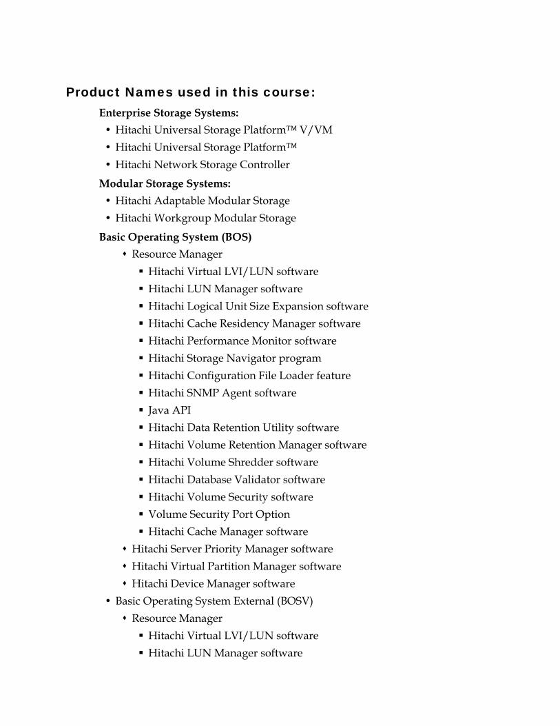
Product Names used in this course: Enterprise Storage Systems:
Hitachi Universal Storage Platform™ V/VM Hitachi Universal Storage Platform™ Hitachi Network Storage Controller
Modular Storage Systems: Hitachi Adaptable Modular Storage Hitachi Workgroup Modular Storage
Basic Operating System (BOS) Resource Manager
Hitachi Virtual LVI/LUN software Hitachi LUN Manager software Hitachi Logical Unit Size Expansion software Hitachi Cache Residency Manager software Hitachi Performance Monitor software Hitachi Storage Navigator program Hitachi Configuration File Loader feature Hitachi SNMP Agent software Java API Hitachi Data Retention Utility software Hitachi Volume Retention Manager software Hitachi Volume Shredder software Hitachi Database Validator software Hitachi Volume Security software Volume Security Port Option Hitachi Cache Manager software
Hitachi Server Priority Manager software Hitachi Virtual Partition Manager software Hitachi Device Manager software
Basic Operating System External (BOSV) Resource Manager
Hitachi Virtual LVI/LUN software Hitachi LUN Manager software

Hitachi Logical Unit Size Expansion software Hitachi Cache Residency Manager software Hitachi Performance Monitor software Hitachi Storage Navigator program Hitachi Configuration File Loader feature Hitachi SNMP Agent software Java API Hitachi Data Retention Utility software Hitachi Volume Retention Manager software Hitachi Volume Shredder software Hitachi Database Validator software Hitachi Volume Security software Volume Security Port Option Hitachi Cache Manager software
Hitachi Server Priority Manager software Hitachi Virtual Partition Manager software Hitachi Device Manager software Hitachi Universal Volume Manager software
Hitachi Storage Command Suite Hitachi Tuning Manager Hitachi Storage Services Manager Hitachi Storage Services Manager for NetApp Hitachi Custom Reporter (for Hitachi Storage Services Manager) Hitachi QoS for Oracle Hitachi QoS for Sybase Hitachi QoS for Microsoft® Exchange Hitachi QoS for Microsoft® SQL Server Hitachi QoS for Intersystems® Caché Hitachi QoS for File Servers Hitachi Chargeback Hitachi Path Provisioning Hitachi Global Reporter Hitachi Dynamic Link Manager Hitachi Dynamic Link Manager Advanced

Hitachi Global Link Availability Manager Hitachi Protection Manager Hitachi Replication Manager Hitachi Backup Services Manager Hitachi Tiered Storage Manager Hitachi Storage Capacity Reporter powered by APTARE®
Other Products Hitachi TrueCopy® Heterogeneous Remote Replication software TrueCopy Heterogeneous Remote Replication software bundle for IBM® z/OS® Hitachi Universal Replicator software for IBM® z/OS® Hitachi Copy-on-Write Snapshot software Hitachi ShadowImage® Heterogeneous Replication software Hitachi ShadowImage® Heterogeneous Replication software fro z/OS Compatible Mirroring for IBM FlashCopy Version 2 Compatible PAV software for IBM z/OS Compatible Replication software for IBM XRC Hitachi Cross-OS File Exchange software Hitachi Cross-OS File Exchange Code Converter option

HDS Confidential: For distribution only to authorized parties. Page vi
Contents
INTRODUCTION .............................................................................. VII
LAB ACTIVITY 1 STORAGE NAVIGATOR PROGRAM........................1-1
LAB ACTIVITY 2 LUN MANAGEMENT ...........................................2-1
LAB ACTIVITY 3 UNIVERSAL VOLUME MANAGER SOFTWARE.........3-1
LAB ACTIVITY 4 VIRTUAL LUN (VLL)..........................................4-1
LAB ACTIVITY 5 SHADOWIMAGE SOFTWARE OPERATIONS ............5-1
LAB ACTIVITY 6 DYNAMIC PROVISIONING SOFTWARE ...................6-1
LAB ACTIVITY 7 VIRTUAL PARTITION MANAGER ...........................7-1

HDS Confidential: For distribution only to authorized parties. Page vii
Introduction NORTH AMERICAN LAB SETUP GUIDE:
Minimum Lab Requirements Two host systems, one running Microsoft® Windows® 2003 and one with Sun Solaris, each connected to the Hitachi Universal Storage Platform™ V or VM Storage platform using a host bus adapter (HBA)
One Universal Storage Platform and Universal Storage Platform V or VM One midrange storage, Hitachi Thunder 9200™ Series modular storage system, Hitachi Thunder 9500™ V Series modular storage system, Hitachi Workgroup Modular Storage or Adaptable Modular Storage systems

Contents Hitachi Enterprise Hardware and Software Fundamentals- USP V
Page viii HDS Confidential: For distribution only to authorized parties.
Configuration Hardware Connections (will vary depending on resources)
Note: Depending on the hardware assigned to your class, the setup will be different, in other words, host IP addresses, and switch connections and external hardware.
Check with your instructor for the actual configuration that you will have.
Sun Host
2A
4A
6A
8A
2B
4B
6B
8B
1A
3A
5A
7A
1B
3B
5B
7B
9990V/9985V (USPV/VM)
Midrange RAID Subsystem
Controller 0 A BController 0 A BA BAA BB
Controller 1 A BController 1 A BA BAA BB
Lab Host-to-Storage Cabling
Local Area Connection
Windows Host
Local Area Connection
Port 0HBA
Port 0HBA
Port 0HBA
Port 0HBA
External Storage5 – 25 GB LUNsExternal Storage5 – 25 GB LUNs
02
46
810
1214
13
57
911
1315
0022
4466
881010
12121414
1133
5577
991111
13131515
Brocade Switch

Hitachi Enterprise Hardware and Software Fundamentals- USP V Contents
HDS Confidential: For distribution only to authorized parties. Page ix
Universal Storage Platform V or VM Emulation The following table lists the configuration of the Universal Storage Platform V or VM storage subsystem:
Control Unit (CU) Emulation LDEV Capacity LDEV Assignments 00 OPEN-V 2 GB 00-31 01 OPEN-V 4 GB 00-18 01 OPEN-V 2 GB 20-2B 05 OPEN-V variable 00
CU 06 will be used for the configuration of external volumes.
Midrange and Enterprise Configuration The following table lists the configuration of the midrange storage subsystem used to supply external volumes to the Universal Storage Platform V/VM storage system:
External Storage Subsystem
RAID Group
RAID Level Emulation LUN
Capacity
Number of LUNs presented to the Universal Storage Platform V/VM
Any RAID 5 N/A 25GB 5
In addition, the image for Solaris should be the standard java desktop and
Microsoft Windows 2003 for the Windows host.

HDS Confidential: For distribution only to authorized parties. Page 1-1
Lab Activity 1 Storage Navigator Program
Introduction
Lab Objectives Upon completion of this lab project, the learner should be able to:
Start a Storage Navigator program session to your instructor-assigned Hitachi Universal Storage Platform™ V or VM using the Java-based web browser of one of your instructor-assigned host systems
Register Universal Storage Platform V or VM with the Storage Navigator Storage Device List
Logon as Administrator and verify the License Keys Create additional login user IDs and passwords Save the Configuration file Download the Audit Log Display a System Information Message Reference Code (SIMRC) and display its description
Display Basic Port, LUN and LDEV information Exit (stop) the Storage Navigator program session
Reference In addition to the Student Guide, several Hitachi reference manuals are available on the desktop of each Microsoft Windows host system.
Hitachi Universal Storage Platform V/VM Storage Navigator User's Guide

Storage Navigator Program Part 1: Instructional Steps
Page 1-2 HDS Confidential: For distribution only to authorized parties.
Part 1: Instructional Steps
Setup Instructions: Your first task is to gather information required to register a Universal Storage Platform V or VM with Storage Navigator program.
1. Ask your instructor what Hitachi storage system is assigned to your class and your group.
2. Document the system Serial Number, IP Address, and Nickname of each Universal Storage Platform V OR VM.
Running the Storage Navigator Program A Java-based Web browser is required to run a Storage Navigator program. A valid version of the Java Runtime Environment (JRE) must be installed on your PC. The JRE is contained on the microcode CD-ROM supplied with the Universal Storage Platform V or VM and it has already been installed on your lab host systems and the service processor (SVP).
The Storage Navigator PC: Can be attached to several storage systems using the TCP/IP local-area network (LAN).
Communicates directly with the service processor (SVP) of each attached subsystem to obtain subsystem configuration and status information and to send user-requested commands to the subsystem.
Storage Navigator program is now a Java Application and no longer runs within the browser screen. The RMI method is more secure than HTML.
Start Storage Navigator Program from a Host PC 1. From your assigned classroom PC, start Internet Explorer.
2. In the web browser, specify the following URL: http://xxx.xxx.xxx.xxx
where xxx.xxx.xxx.xxx is the IP Address of your Universal Storage Platform V or VM.

Storage Navigator Program Part 1: Instructional Steps
HDS Confidential: For distribution only to authorized parties. Page 1-3
When connected to the SVP, the first screen you see is the Storage Device List. It lists all the registered Hitachi storage systems.
If registered systems are deleted, the browser may continue to display the entries until the cache is cleared. Using the keyboard, press the F5 key or click Refresh in the browser to clear the cache. The deleted entries will no longer be displayed.
Log on and Register another Storage Platform All Storage Navigator PC (web client) for Universal Storage Platform V or VM users, are required to log on to the Storage Navigator SVP (web server) with a valid User ID and Password before executing the Storage Navigator Java applet program.
Only the Storage Navigator Administrator (User ID of root) can register a Storage Navigator user and assign or modify the user's access privileges (write permissions for storage system feature options).
1. Click Edit (the small icon of an ink pen) and create a new entry (register) in the Storage Device List.

Storage Navigator Program Part 1: Instructional Steps
Page 1-4 HDS Confidential: For distribution only to authorized parties.
2. Enter root as the User ID, and root as the Password, and then click Login. If a
Security Warning appears, click to deselect Alert, and then click Continue.
Any registered entries turn pink to indicate the edit mode and the Edit and Delete buttons appear.
3. Click New Entry.

Storage Navigator Program Part 1: Instructional Steps
HDS Confidential: For distribution only to authorized parties. Page 1-5
4. Enter the data of the storage system as shown above (varies from class to class)
and then click Submit.
5. Click OK to confirm.
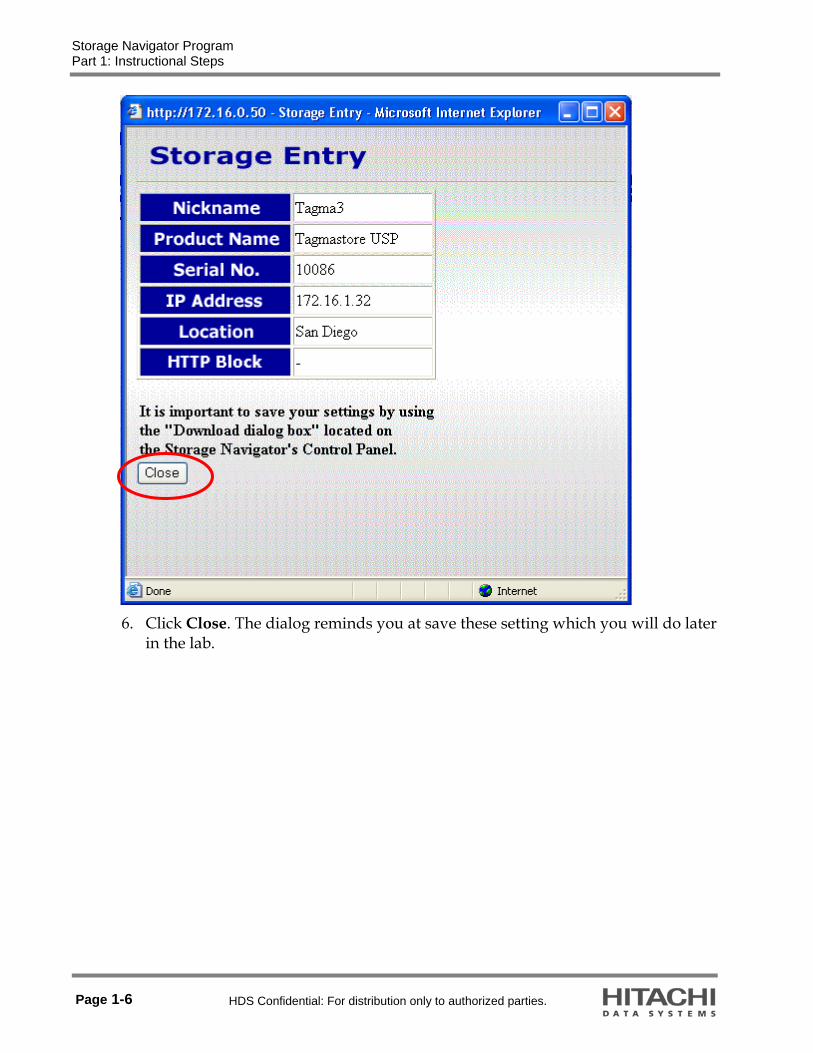
Storage Navigator Program Part 1: Instructional Steps
Page 1-6 HDS Confidential: For distribution only to authorized parties.
6. Click Close. The dialog reminds you at save these setting which you will do later
in the lab.

Storage Navigator Program Part 1: Instructional Steps
HDS Confidential: For distribution only to authorized parties. Page 1-7
7. Click on the pen icon to exit and return to the Storage Device List. The Storage Device List should look similar to this.

Storage Navigator Program Part 1: Instructional Steps
Page 1-8 HDS Confidential: For distribution only to authorized parties.
Logon as Administrator and verify the License Keys 1. Connect to your assigned system by clicking on its entry in the Storage Device
List.
Note: There is a short pause while the connection is being made.
2. Connect as Administrator by entering the UserID and password, and then click Login.
User ID = root
Password = root
Note: Before the beginning of the class your system should have been reconfigured and all of the license keys reloaded.

Storage Navigator Program Part 1: Instructional Steps
HDS Confidential: For distribution only to authorized parties. Page 1-9
3. Go to the License Key tab as illustrated below.
Look at the small icon of the lock in the upper portion of the window. The lock is open and the background is blue indicating that Storage Navigator program is in View mode. In order to change any parameter, Write mode must be invoked.

Storage Navigator Program Part 1: Instructional Steps
Page 1-10 HDS Confidential: For distribution only to authorized parties.
4. Verify that all of the keys have been installed by using the scroll bar on the right.
5. Note the OPEN Drive Capacity, the Mainframe Drive Capacity, and SATA.
Question 1: What is the only operation that you are allowed to perform?
See the answers in Part 2 of this Lab Activity.

Storage Navigator Program Part 1: Instructional Steps
HDS Confidential: For distribution only to authorized parties. Page 1-11
Create Additional Accounts 1. Select the Go menu > Security > Account to register an additional user.
2. Click on the pen icon to set up modify mode and then under Account, right-click SA and select New User.

Storage Navigator Program Part 1: Instructional Steps
Page 1-12 HDS Confidential: For distribution only to authorized parties.
Use this dialog to create the new User ID and Password and then identify what functions the new user can utilize.
3. Enter two new users (guest and view): For the guest user, leave each function in Modify mode For the view user, change all of the functions to View mode. Use password as the password for both new users.
After each user is set up, click Apply to save each new entry.

Storage Navigator Program Part 1: Instructional Steps
HDS Confidential: For distribution only to authorized parties. Page 1-13
The two new User IDs should be listed.
All the functions of the guest user should be available as indicated by Modify. All of the functions of the view user will not be available, View.
4. Exit the Storage Navigator program.
5. Login using one of your new User IDs.
Question 1: What are the only options that you are allowed to perform?
________________________________________ (Answer in Part 2 of this lab project)
6. Log out (Exit all the windows) from Storage Navigator program.
7. Log in again as root and complete the remaining steps of the lab project as Administrator.

Storage Navigator Program Part 1: Instructional Steps
Page 1-14 HDS Confidential: For distribution only to authorized parties.
Set Environmental Parameters and Download the Configuration
1. To open the Tool Panel, use web browser of the Storage Navigator computer. http://<ipaddress>/cgi-bin/utility/toolpanel.cgi
2. Login with UserID root and password root. The Tool Panel dialog appears.
3. Click Control Panel.
The Set Env. tab page displays. Use this to set the various parameters that control how Storage Navigator program connects to the SVP.
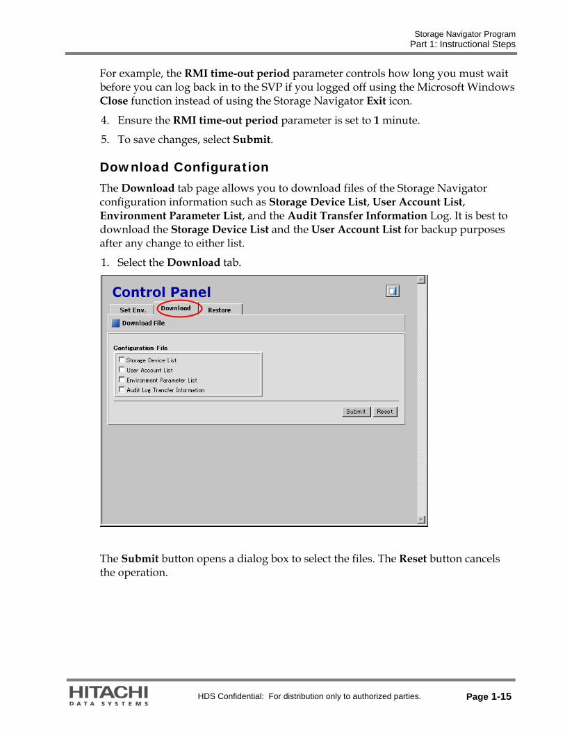
Storage Navigator Program Part 1: Instructional Steps
HDS Confidential: For distribution only to authorized parties. Page 1-15
For example, the RMI time-out period parameter controls how long you must wait before you can log back in to the SVP if you logged off using the Microsoft Windows Close function instead of using the Storage Navigator Exit icon.
4. Ensure the RMI time-out period parameter is set to 1 minute.
5. To save changes, select Submit.
Download Configuration The Download tab page allows you to download files of the Storage Navigator configuration information such as Storage Device List, User Account List, Environment Parameter List, and the Audit Transfer Information Log. It is best to download the Storage Device List and the User Account List for backup purposes after any change to either list.
1. Select the Download tab.
The Submit button opens a dialog box to select the files. The Reset button cancels the operation.

Storage Navigator Program Part 1: Instructional Steps
Page 1-16 HDS Confidential: For distribution only to authorized parties.
2. Check the check boxes for Storage Device List, User Account List, and Environment Parameter List, and click Submit.

Storage Navigator Program Part 1: Instructional Steps
HDS Confidential: For distribution only to authorized parties. Page 1-17
3. Click Download and then specify the file name to save (or accept the default).

Storage Navigator Program Part 1: Instructional Steps
Page 1-18 HDS Confidential: For distribution only to authorized parties.
4. Decompress the downloaded file (*.tgz) as required. To create the *.tgz file, the directory structure is first archived using the tar command and then compressed using the gzip command. To decompress the *.tgz file, you will need to use a tool that supports both tar and gzip commands, such as WinZip.

Storage Navigator Program Part 1: Instructional Steps
HDS Confidential: For distribution only to authorized parties. Page 1-19
Restore Configuration
The Restore tab page includes the Archive File check box and text box. You can specify the compressed backup file that has been downloaded, using the Download tab, as the file you restore. The file extension must be tgz. Browse to select the file.
(Optional) As an exercise, restore the saved configuration from the download that you performed.

Storage Navigator Program Part 1: Instructional Steps
Page 1-20 HDS Confidential: For distribution only to authorized parties.
Display System Information Messages 1. On the main menu bar click the Go menu > System Information > Status
2. Right-click an entry and select Detail.

Storage Navigator Program Part 1: Instructional Steps
HDS Confidential: For distribution only to authorized parties. Page 1-21
Display the Audit Log The Audit Log function allows you to record the access and configuration changes made to your storage system. The audit log can be used to investigate when an incorrect setup is performed or when a problem occurs in the storage system.
To access the audit log:
1. On the main menu, click on the audit icon.
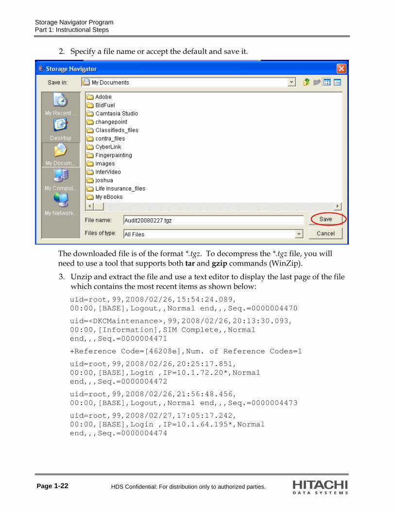
Storage Navigator Program Part 1: Instructional Steps
Page 1-22 HDS Confidential: For distribution only to authorized parties.
2. Specify a file name or accept the default and save it.
The downloaded file is of the format *.tgz. To decompress the *.tgz file, you will need to use a tool that supports both tar and gzip commands (WinZip).
3. Unzip and extract the file and use a text editor to display the last page of the file which contains the most recent items as shown below: uid=root,99,2008/02/26,15:54:24.089, 00:00,[BASE],Logout,,Normal end,,,Seq.=0000004470
uid=<DKCMaintenance>,99,2008/02/26,20:13:30.093, 00:00,[Information],SIM Complete,,Normal end,,,Seq.=0000004471
+Reference Code=[46208e],Num. of Reference Codes=1
uid=root,99,2008/02/26,20:25:17.851, 00:00,[BASE],Login ,IP=10.1.72.20*,Normal end,,,Seq.=0000004472
uid=root,99,2008/02/26,21:56:48.456, 00:00,[BASE],Logout,,Normal end,,,Seq.=0000004473
uid=root,99,2008/02/27,17:05:17.242, 00:00,[BASE],Login ,IP=10.1.64.195*,Normal end,,,Seq.=0000004474

Storage Navigator Program Part 1: Instructional Steps
HDS Confidential: For distribution only to authorized parties. Page 1-23
4. Verify the Port Settings using the Basic Information command.
5. Note the settings for the ports:
6. Click on the other tabs, such as LUN and LDEV to see the information that is displayed for this storage system.
This ends the guided portion of the lab project.
If you want to go back and practice what you have learned, feel free to do so, but keep in mind that you need to complete the review questions and have them ready to go over when the class reconvenes in the classroom.
Make sure you leave the system in the same state that it was in at the end of the guided portion of the lab project – this ensures that the system will be in a state that supports the following lab projects.

Storage Navigator Program Part 2: Answers to Embedded Questions
Page 1-24 HDS Confidential: For distribution only to authorized parties.
Part 2: Answers to Embedded Questions Question 1: What is the only operation that you are allowed to perform?
Answer: The ones you set to Modify.
Part 3: Review Questions 1. How do you connect to the SVP for Universal Storage Platform V or VM in order
to run the Storage Navigator program?
2. What utility allows you to change the LUN Manager settings with a configuration file?
3. Which user account must you use to register a Universal Storage Platform V or VM with the Storage Device List?
4. Any user can enable or disable the various Storage Navigator program functions (such as LUN manager, Hitachi TrueCopy™ Heterogeneous Remote Replication software bundle, Hitachi ShadowImage In-System Replication software.). True or False
5. How must you log off from Storage Navigator program?
6. What happens if you log off from Storage Navigator program using the Microsoft Windows Close function?
7. The required JRE is contained on the subsystems microcode CD-ROM. True or False
Lab End

HDS Confidential: For distribution only to authorized parties. Page 2-1
Lab Activity 2 LUN Management
Introduction
Lab Objectives Upon completion of the lab project, the learner should be able to:
Use Storage Navigator program to configure a Hitachi Universal Storage Platform™ V or VM port to support a switched connection by setting the Fabric and Connection parameters correctly
Use the Emulex or QLogic management GUIs to determine the World Wide Names (WWNs) of each Emulex or QLogic HBA
Use the Storage Navigator program to associate each HBA WWN to the actual Universal Storage Platform V or VM port
Use the Storage Navigator program to enable port LUN Security and create host groups to support connections to a Universal Storage Platform V or VM port for a Microsoft Windows and Sun Solaris host operating system
Use the Storage Navigator program to register the WWN of a host HBA with the host group
Use the Storage Navigator program to associate (map) a logical device (LDEV) to a Universal Storage Platform V or VM port
Use the Emulex or QLogic management GUIs to configure each HBA to support a switched connection
Use the Storage Navigator program to display the Fibre Channel link status of each Universal Storage Platform V or VM host port

LUN Management Introduction
Page 2-2 HDS Confidential: For distribution only to authorized parties.
Use the Emulex or QLogic management GUIs to verify that each HBA detects the logical units (LUNs) of the Universal Storage Platform V or VM mapped to that HBA
Configure the Solaris configuration file /kernel/drv/sd.conf to allow Solaris access to the HBA detected targets (LUNs)
Write a label to a Solaris LUN Write a Write Signature to a Microsoft Windows LUN
Reference In addition to the Student Guide, several Hitachi reference manuals are available on the desktop of each Microsoft Windows host system.
Hitachi Universal Storage Platform V/VM LUN Manager User's Guide Hitachi Universal Storage Platform V/VM Storage Navigator User's Guide
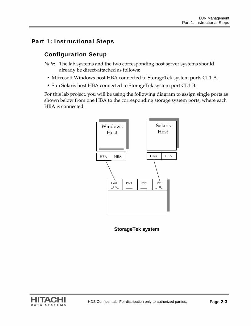
LUN Management Part 1: Instructional Steps
HDS Confidential: For distribution only to authorized parties. Page 2-3
Part 1: Instructional Steps
Configuration Setup Note: The lab systems and the two corresponding host server systems should
already be direct-attached as follows: Microsoft Windows host HBA connected to StorageTek system ports CL1-A. Sun Solaris host HBA connected to StorageTek system port CL1-B.
For this lab project, you will be using the following diagram to assign single ports as shown below from one HBA to the corresponding storage system ports, where each HBA is connected.
StorageTek system
Windows Host
Solaris Host
HBA HBA HBA HBA
Port _1A_
Port ____
Port ____
Port _1B_

LUN Management Part 1: Instructional Steps
Page 2-4 HDS Confidential: For distribution only to authorized parties.
StorageTek 9990V/9985V (Universal Storage Platform V or VM) Emulation Configuration
The following table lists the configuration of the 9990V/9985V storage subsystem:
Control Unit (CU) Emulation LDEV Capacity LDEV Assignments 00 OPEN-V 2 GB 00-31 01 OPEN-V 4 GB 00-18 01 OPEN-V 2 GB 20-2B 05 OPEN-V variable 00
CU 06 will be used for the configuration of external volumes.
Configure the Universal Storage Platform 9990V/9985V Host Ports
Before you map logical units (LUNs) to storage system host groups and attempt to discover them at the host systems, you must verify that the port properties are set up correctly.
For a switch— Fabric is set to Enable and Connection is set to PtoP.
The Host Speed can be set up as Auto, 1 or 2GB/sec, depending upon the HBA speed.
Note: This section of the lab project instructs you to check the Fibre Channel topology settings and Port Address settings of each host port and change them as required to match the configuration expected by the lab project.
1. From your assigned classroom PC, use the web browser and connect to your assigned Universal Storage Platform V or VM.
2. Click the View icon (small ink pen icon) to change to Modify mode.
3. On the main screen, click on the Go menu >LUN Manager > Port. The Port tab page appears.
4. In the Package pane under Subsystem, select the Fibre folder.

LUN Management Part 1: Instructional Steps
HDS Confidential: For distribution only to authorized parties. Page 2-5

LUN Management Part 1: Instructional Steps
Page 2-6 HDS Confidential: For distribution only to authorized parties.
5. Select port CL1-A from the Select a Port list on the Change Port Mode panel.
6. Verify or change the port mode settings for port CL1-A (per the table below), and then click Set. Do the same for Port CL1-B.
Parameter Setting
Host Speed Auto(1 Gbps)
Fibre Address The Fibre address is arbitrary since we are connected
to a switch and does not need to be set.
CL1-A = EF (TID 0)
CL1-B = D9 (TID 1) Fabric Enable
Connection P to P

LUN Management Part 1: Instructional Steps
HDS Confidential: For distribution only to authorized parties. Page 2-7
7. Next scroll to the right and gather the WWN for each of these ports so that we can verify these on the host systems.
8. Enter the WWNs for the ports. CL1-A _____________________________ CL1-B _____________________________

LUN Management Part 1: Instructional Steps
Page 2-8 HDS Confidential: For distribution only to authorized parties.
Emulex HBA (LP10000): Identify WWN and Verify Topology Settings
In this section you display and record the WWPNs of each HBA port (in the Microsoft Windows host) and verify that the topology settings are configured to support switched connections to the Universal Storage Platform V or VM ports.
1. From your assigned classroom PC, use the Remote Desktop Connection utility and connect to your Microsoft Windows host system as Administrator (password = hds).
2. From the Start menu, start the HBAnywhere Utility.
3. Once it starts, the detected adapters are listed under Discovered Elements.
4. Record the Port WWN for HBA 0 __________________________

LUN Management Part 1: Instructional Steps
HDS Confidential: For distribution only to authorized parties. Page 2-9
QLogic HBA: Identify WWN and Verify Topology Settings In this section you display and record the WWPNs of each port of the Host Bus Adapter (in the Sun host) and verify that the topology settings are configured to support switched connections to the Universal Storage Platform V or VM ports.
1. From your assigned classroom PC, start the VNC Viewer application with Start menu> Programs > Real VNC > Run VNC Viewer.
2. Enter the IP Address of the Sun system with the characters: 1 appended to the
address, and then click OK. For example: 172.16.1.74:1
3. Enter the password hitachi.
A vnc session should start with the Sun system desktop displayed and an open window. If prompted for a login the ID is root and password root.

LUN Management Part 1: Instructional Steps
Page 2-10 HDS Confidential: For distribution only to authorized parties.
4. Start the Qlogic GUI by clicking on the SAN Surfer icon as shown below.
5. Click Connect.

LUN Management Part 1: Instructional Steps
HDS Confidential: For distribution only to authorized parties. Page 2-11
6. Choose localhost as the connection and click Connect
7. In the Hostname panel on the left, click on Port 0 and record the WWPN for Port 0 ________________________
8. Verify that the Actual Connection Mode parameter is set to Point to Point.
9. Minimize the VNC connection window to your assigned Sun host.

LUN Management Part 1: Instructional Steps
Page 2-12 HDS Confidential: For distribution only to authorized parties.
Associate the HBA Connections to the Storage System 1. Open the Storage Navigator window.
2. Click Reset to reset the RMI-time-out period for Modify parameter. This puts Storage Navigator back into Modify mode if it had expired (set to 30 minutes) during the time you were accessing the HBAs.
3. Select the LUN Manager tab. The LU Path & Security page appears.
4. In the LU Path top-left navigation pane, expand the Fibre folder by clicking the plus sign (+). The list of channel adapter (CHA) fibre ports appears.
5. Click on port CL1-A.

LUN Management Part 1: Instructional Steps
HDS Confidential: For distribution only to authorized parties. Page 2-13
6. For WWN, Port (lower left pane), select CL1-A.
The WWN of the HBAs connected to the switch are listed in the table. (The WWNs on your screen may be different from this example).
7. You can now visually associate the storage system port to the actual host HBA port recorded previously. Do the same for Port CL1-B.

LUN Management Part 1: Instructional Steps
Page 2-14 HDS Confidential: For distribution only to authorized parties.
Creating Host Groups When using a Fibre Channel switch, multiple server hosts of different platforms can be connected to one Fibre Channel port of a storage system. When configuring your system, you must group server hosts by host groups. For example, if Sun Solaris hosts and Microsoft Windows hosts are connected to the same Fibre Channel port, you must create one host group for the Sun Solaris hosts and create another host group for the Microsoft Windows hosts. Next, you must register Sun Solaris hosts to the corresponding host group and also register Microsoft Windows hosts to the other host group.
Even if you are not using a switch (that is, your connections are direct-attached), in order to show how host groups are created you will be instructed to create two host groups (sunlab and winlab). The procedure for registering the hosts to a host group will be performed later in the lab project.
Create Your First Host Group on Port CL1-A for the Microsoft Windows Host
1. Click the GO menu > LUN Manager.
2. Before you can create host groups, you must enable LUN Security. Before the start of class, all the storage system ports were configured with LUN Security Disabled.
In the LU Path pane, with the Fibre folder expanded, right-click on port CL1-A. Select LUN Security: Disable->Enable, and then left-click. This toggles the setting from Disable to Enable.
Notice that all the ports are currently disabled.

LUN Management Part 1: Instructional Steps
HDS Confidential: For distribution only to authorized parties. Page 2-15
3. Click OK.
Notice the status now indicates Enabled.
4. Expand port CL1-A.
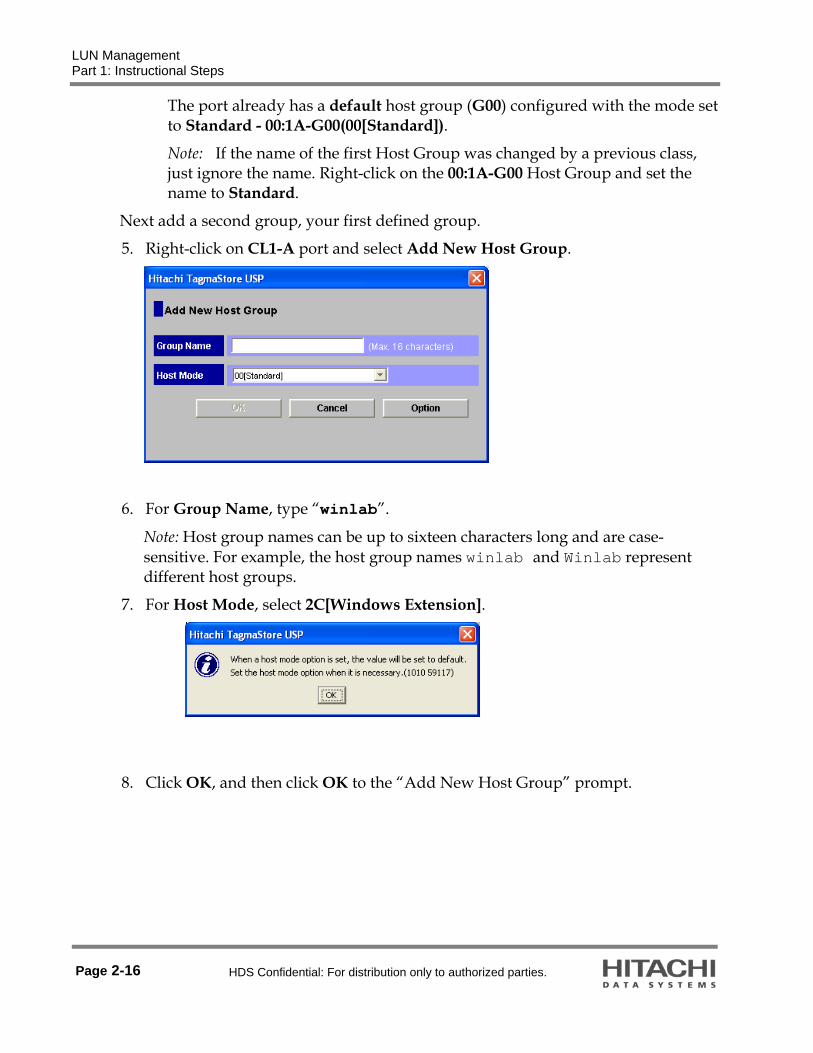
LUN Management Part 1: Instructional Steps
Page 2-16 HDS Confidential: For distribution only to authorized parties.
The port already has a default host group (G00) configured with the mode set to Standard - 00:1A-G00(00[Standard]).
Note: If the name of the first Host Group was changed by a previous class, just ignore the name. Right-click on the 00:1A-G00 Host Group and set the name to Standard.
Next add a second group, your first defined group.
5. Right-click on CL1-A port and select Add New Host Group.
6. For Group Name, type “winlab”.
Note: Host group names can be up to sixteen characters long and are case-sensitive. For example, the host group names winlab and Winlab represent different host groups.
7. For Host Mode, select 2C[Windows Extension].
8. Click OK, and then click OK to the “Add New Host Group” prompt.

LUN Management Part 1: Instructional Steps
HDS Confidential: For distribution only to authorized parties. Page 2-17
When selecting a host mode, you must consider the platform type as shown in the following table:
Host mode When to select this mode? 00 Standard When registering Red Hat Linux server hosts or IRIX server hosts in the host group
03 HP When registering HP-UX server hosts in the host group
04 Sequent When registering DYNIX/ptx server hosts in the host group
05 OpenVMS When registering OpenVMS server hosts in the host group
07 Tru64 When registering Tru64 server hosts in the host group
09 Solaris When registering Sun Solaris server hosts in the host group
0A NetWare When registering NetWare server hosts in the host group
0C Windows When registering Microsoft Windows NT or Microsoft Windows 2000 server hosts in the host group
OE HI-UX When registering Hitachi Unix server hosts in the host group
0F AIX When registering IBM® AIX® server hosts in the host group
2C Windows Extension When registering Windows Extension server hosts in the host group
4C UVM When registering another Universal Storage Platform storage system using Hitachi Universal Volume Manager software(UVM)
9. Click Apply in the main window, and then click OK at the “Do you want to
apply?” prompt.
10. Click OK to “The Requested operation is complete” prompt.
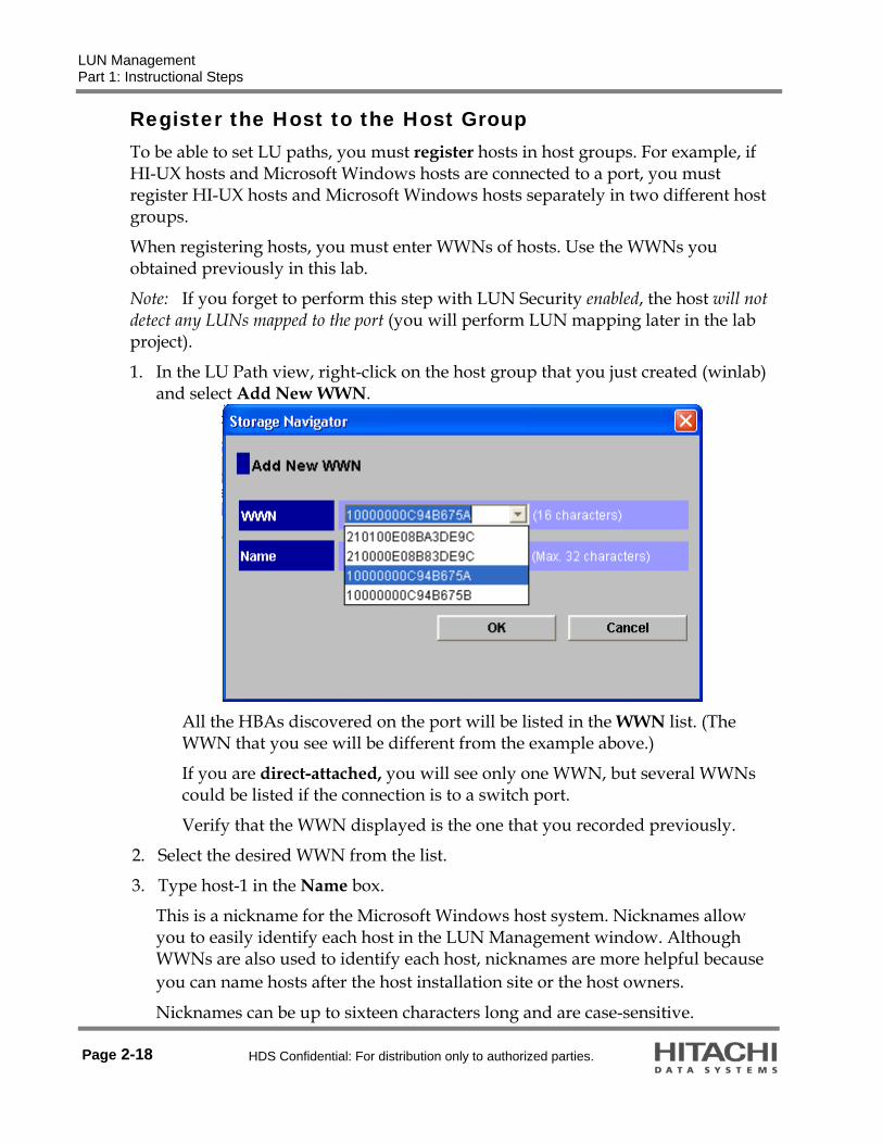
LUN Management Part 1: Instructional Steps
Page 2-18 HDS Confidential: For distribution only to authorized parties.
Register the Host to the Host Group To be able to set LU paths, you must register hosts in host groups. For example, if HI-UX hosts and Microsoft Windows hosts are connected to a port, you must register HI-UX hosts and Microsoft Windows hosts separately in two different host groups.
When registering hosts, you must enter WWNs of hosts. Use the WWNs you obtained previously in this lab.
Note: If you forget to perform this step with LUN Security enabled, the host will not detect any LUNs mapped to the port (you will perform LUN mapping later in the lab project).
1. In the LU Path view, right-click on the host group that you just created (winlab) and select Add New WWN.
All the HBAs discovered on the port will be listed in the WWN list. (The WWN that you see will be different from the example above.)
If you are direct-attached, you will see only one WWN, but several WWNs could be listed if the connection is to a switch port.
Verify that the WWN displayed is the one that you recorded previously.
2. Select the desired WWN from the list.
3. Type host-1 in the Name box.
This is a nickname for the Microsoft Windows host system. Nicknames allow you to easily identify each host in the LUN Management window. Although WWNs are also used to identify each host, nicknames are more helpful because you can name hosts after the host installation site or the host owners.
Nicknames can be up to sixteen characters long and are case-sensitive.

LUN Management Part 1: Instructional Steps
HDS Confidential: For distribution only to authorized parties. Page 2-19
4. Click OK.
5. Expand the winlab host group to see the WWN and nickname associated to the group.
6. Click Apply in the Storage Navigator main window, and then click OK to the “Do you want to apply?” prompt.
7. Click OK to “The Requested operation is complete.” prompt.

LUN Management Part 1: Instructional Steps
Page 2-20 HDS Confidential: For distribution only to authorized parties.
8. Complete the Host Group configuration for the other port, CL1-B. The group name should be sunlab, the host mode for Solaris is 09 and the name is host-2. When you are finished, the expanded tree should look like the following screen shot (see next page).

LUN Management Part 1: Instructional Steps
HDS Confidential: For distribution only to authorized parties. Page 2-21
Register the Host to the Host Group — Associate Host Groups to Logical Volumes (LUN Mapping)
LUN Management lets you define LU paths by associating host groups with logical volumes. The following steps guide you through the process of associating (mapping) several logical devices (LDEVs) to the host groups of the individual ports of the host connections.
The following table shows how the mapping will be configured:
All LUNs will come from Control Unit 01
Port LUN LDEV LUN 0 01:00
LUN 1 01:01
LUN 2 01:02 CL1-A
LUN 3 01:02
1. Expand CL1-A port and then click winhost host group.

LUN Management Part 1: Instructional Steps
Page 2-22 HDS Confidential: For distribution only to authorized parties.
Note: By default Control Unit 00 (CU 00) should be selected in the CU list at the right-middle end of the LDEV panel.
2. Select Control Unit 01.
3. Select 01:00 thru 01:03 (shift-click) in the LDEV column of the LDEV panel.
4. Click 0000 in the LUN column of the LU Path panel.
Note: The function Add LU Path (in the center of the panel) activates.
5. Click Add LU Path. The Check Paths dialog box displays.
6. Click OK.
7. Click Apply, and then click OK to the “Do you want to apply?” prompt, and then click OK to “The requested operation is complete.” prompt.

LUN Management Part 1: Instructional Steps
HDS Confidential: For distribution only to authorized parties. Page 2-23
Verify the Devices on the Windows Host 1. Start a remote desktop session to the Windows host that is connected to port
CL1-A.
2. When prompted, enter the login as Administrator and the password as hds.
3. Right-click on the My Computer icon and select Manage.
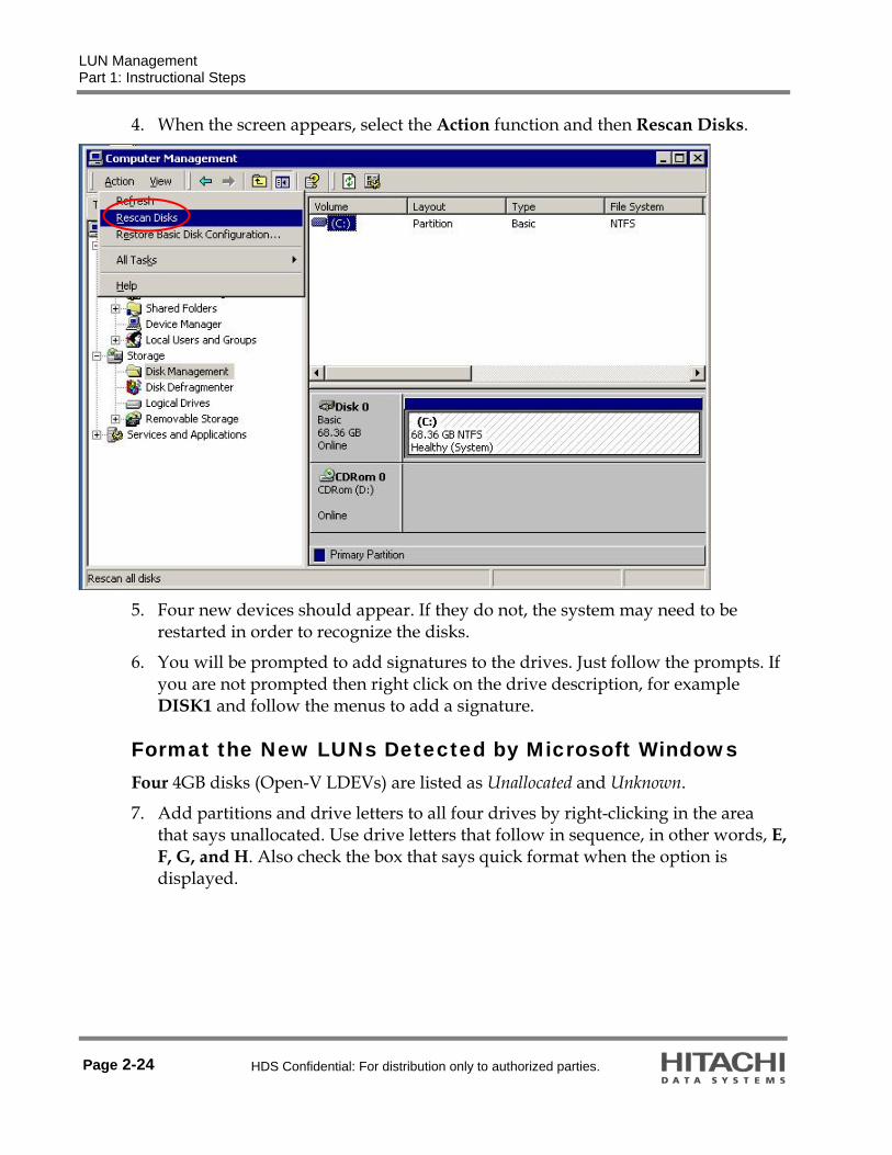
LUN Management Part 1: Instructional Steps
Page 2-24 HDS Confidential: For distribution only to authorized parties.
4. When the screen appears, select the Action function and then Rescan Disks.
5. Four new devices should appear. If they do not, the system may need to be
restarted in order to recognize the disks.
6. You will be prompted to add signatures to the drives. Just follow the prompts. If you are not prompted then right click on the drive description, for example DISK1 and follow the menus to add a signature.
Format the New LUNs Detected by Microsoft Windows Four 4GB disks (Open-V LDEVs) are listed as Unallocated and Unknown.
7. Add partitions and drive letters to all four drives by right-clicking in the area that says unallocated. Use drive letters that follow in sequence, in other words, E, F, G, and H. Also check the box that says quick format when the option is displayed.

LUN Management Part 1: Instructional Steps
HDS Confidential: For distribution only to authorized parties. Page 2-25
8. Verify that the drives are allocated and formatted as shown below:

LUN Management Part 1: Instructional Steps
Page 2-26 HDS Confidential: For distribution only to authorized parties.
9. Copy the WIN2K file system to the E: drive to verify the status.

LUN Management Part 1: Instructional Steps
HDS Confidential: For distribution only to authorized parties. Page 2-27
Associate Host Groups to Logical Volumes (LUN Mapping) for the Solaris Host
1. Perform the same steps as you did for the Windows host and map the LUNs on port CL1-B.
2. Map the LUNs according to the following table:
All LUNs will come from Control Unit 01
Port LUN LDEV LUN 0 01:0A
LUN 1 01:0B
LUN 2 01:0C CL1-B
LUN 3 01:0D
3. Apply the following:

LUN Management Part 1: Instructional Steps
Page 2-28 HDS Confidential: For distribution only to authorized parties.
Verify the Devices on the Solaris Host
1. Telnet to the assigned host with a login of root and password of root.
2. Use the format command to list the disks that Solaris has access to.
# format
Searching for disks...done
c3t1d1: configured with capacity of 3.99GB
c3t1d2: configured with capacity of 3.99GB
c3t1d3: configured with capacity of 3.99GB
AVAILABLE DISK SELECTIONS:
0. c1t0d0 <SUN72G cyl 14087 alt 2 hd 24 sec 424>
/pci@1c,600000/scsi@2/sd@0,0
1. c1t1d0 <SUN72G cyl 14087 alt 2 hd 24 sec 424>
/pci@1c,600000/scsi@2/sd@1,0
2. c3t1d0 <HITACHI-OPEN-V-SUN-5009 cyl 1090 alt 2 hd 15 sec 512>
/pci@1e,600000/fibre-channel@3/sd@1,0
3. c3t1d1 <HITACHI-OPEN-V-SUN-5009 cyl 1090 alt 2 hd 15 sec 512>
/pci@1e,600000/fibre-channel@3/sd@1,1
4. c3t1d2 <HITACHI-OPEN-V-SUN-5009 cyl 1090 alt 2 hd 15 sec 512>
/pci@1e,600000/fibre-channel@3/sd@1,2
5. c3t1d3 <HITACHI-OPEN-V-SUN-5009 cyl 1090 alt 2 hd 15 sec 512>
/pci@1e,600000/fibre-channel@3/sd@1,3
Specify disk (enter its number):Specify disk (enter its number):
3. Quit the format process by pressing the Control-d (^ d) keys.
4. If the devices do not appear, do the following:
Edit sd.conf
Note: Make a copy of a configuration file before you make changes to it. Your lab system has been configured with copies of files you change during this and following lab projects. The original files have the string .original appended to the file names as they existed after the software installation.

LUN Management Part 1: Instructional Steps
HDS Confidential: For distribution only to authorized parties. Page 2-29
1. Edit the file /kernel/drv/sd.conf and add the four entries as shown below. This example is for target id 1. Yours may be different.
Note: If you are not familiar with vi, you can use the text editor from the desktop Applications menu. Or your instructor may help with vi. There is a summary of vi commands at the end of this chapter.
# Copyright (c) 1992, by Sun Microsystems, Inc.
#ident "@(#)sd.conf 1.9 98/01/11 SMI"
name="sd" class="scsi" class_prop="atapi"
target=0 LUN=0;
name="sd" class="scsi" class_prop="atapi"
target=1 LUN=0;
name="sd" class="scsi" class_prop="atapi"
target=2 LUN=0;
name="sd" class="scsi" class_prop="atapi"
target=3 LUN=0;
Add these lines
name="sd" class="scsi" target=1 lun=0;
name="sd" class="scsi" target=1 lun=1;
name="sd" class="scsi" target=1 lun=2;
name="sd" class="scsi" target=1 lun=3;
Scan New Devices Using Sun Solaris The command, devfsadm, scans for new devices and creates the required device files in the /dev/dsk and /dev/rdsk directories for any new devices it detects.
The –v = verbose mode The –C = Remove all old links
2. Execute devfsadm -v –C
3. Execute the format command again.
4. If the new devices still do not appear then reboot the system using reboot -- -r
5. After the reboot, connect to the Sun host using telnet and log in as root.
6. Execute devfsadm -C
7. Execute the format command again.

LUN Management Part 1: Instructional Steps
Page 2-30 HDS Confidential: For distribution only to authorized parties.
Output of the format command follows. # format
Searching for disks...done
c3t1d2: configured with capacity of 3.99GB
c3t1d3: configured with capacity of 3.99GB
AVAILABLE DISK SELECTIONS:
0. c1t0d0 <SUN72G cyl 14087 alt 2 hd 24 sec 424>
/pci@1c,600000/scsi@2/sd@0,0
1. c1t1d0 <SUN72G cyl 14087 alt 2 hd 24 sec 424>
/pci@1c,600000/scsi@2/sd@1,0
2. c3t1d0 <HITACHI-OPEN-V-SUN-5009 cyl 1090 alt 2 hd 15 sec 512>
/pci@1e,600000/fibre-channel@3/sd@1,0
3. c3t1d1 <HITACHI-OPEN-V-SUN-5009 cyl 1090 alt 2 hd 15 sec 512>
/pci@1e,600000/fibre-channel@3/sd@1,1
4. c3t1d2 <HITACHI-OPEN-V-SUN-5009 cyl 1090 alt 2 hd 15 sec 512>
/pci@1e,600000/fibre-channel@3/sd@1,2
5. c3t1d3 <HITACHI-OPEN-V-SUN-5009 cyl 1090 alt 2 hd 15 sec 512>
/pci@1e,600000/fibre-channel@3/sd@1,3
Specify disk (enter its number):
Write a New Label to Each LUN The new LUNs require a label before the system can access them, therefore use the format command to write a new label to each LUN.
Write the label to the LUNs of Port 0 (c3t1d0, c3t1d1, c3t1d2, and c3t1d3).
Note:: For the system that was used to capture the output of the format command, disk 2 was c3t1d0. Your system numbering is most likely different.
1. Select disk 2 by entering 2 at the “Specify disk (enter its number)” prompt.
selecting c3t1d0
[disk formatted]
Disk not labeled. Label it now?

LUN Management Part 1: Instructional Steps
HDS Confidential: For distribution only to authorized parties. Page 2-31
2. Type Y to the “Disk not labeled. Label it now?” prompt.
Note: The format process outputs the menu of all its functions (commands).
3. Enter label to select the label function.
4. Type Y to the “Ready to label disk, continue?” prompt.
5. Execute the disk function to again display the list of available disks.
6. Select disk 3 by typing 3 at the “Specify disk (enter its number)” prompt, label it and do the same for the remainder of the disks.
7. Enter quit to stop the format process.
8. At the command line prompt, create a file system on the first new disk, mount it, display the statistics and copy data to it as follows:
# newfs /dev/rdsk/c3t1d0s2
newfs: construct a new file system /dev/rdsk/c3t1d0s2: (y/n)? y
/dev/rdsk/c3t1d0s2: 8371200 sectors in 1090 cylinders of 15 tracks, 512 sectors
4087.5MB in 78 cyl groups (14 c/g, 52.50MB/g, 6400 i/g)
super-block backups (for fsck -F ufs -o b=#) at:
32, 108064, 216096, 324128, 432160, 540192, 648224, 756256, 864288, 972320,
7313440, 7421472, 7529504, 7637536, 7745568, 7853600, 7961632, 8069664,
8177696, 8285728,
# mount /dev/dsk/c3t1d0s2 /mnt
# df -k
Filesystem kbytes used avail capacity Mounted on
/dev/dsk/c1t0d0s0 30257446 3498077 26456795 12% /
/proc 0 0 0 0% /proc
mnttab 0 0 0 0% /etc/mnttab
fd 0 0 0 0% /dev/fd
swap 5723720 32 5723688 1% /var/run
swap 5723768 80 5723688 1% /tmp
/dev/dsk/c3t1d0s2 4121934 9 4080706 1% /mnt
# cp -r /usr /mnt &
933
End of Lab

LUN Management Part 2: Command Summary for the vi Editor
Page 2-32 HDS Confidential: For distribution only to authorized parties.
Part 2: Command Summary for the vi Editor This section gives brief descriptions for some of the more useful vi commands.
Cursor control if arrow keys do not function: h, j, k, and l
Delete a character: x
Delete a word: dw
Delete a line: dd
Delete multiple lines: Ndd, where N = number of lines. For Example: 3dd
Undo previous change: u
Exit vi and save any changes: ZZ
Append characters after the cursor: a
Append characters at the end of the line: A
Insert characters before the cursor: i
Open a new line below the cursor: o
Open a new line above the cursor: O
Replace a single character: rx, where x is the new character
Yank and Put Commands
Nyy, where N = number of lines to put into the buffer. For Example: 3yy
Put the buffer text after the cursor: P
Put the buffer text before the cursor: p
Command Line Functions
Put vi into command line mode: Shift: (the prompt changes to the colon character (:)
Quit vi and discard any changes: q!
Force write of changes (overrides file permissions): w!
Quit vi: q

HDS Confidential: For distribution only to authorized parties. Page 3-1
Lab Activity 3 Universal Volume Manager Software
Introduction
Lab Objectives Upon completion of the lab project, you should be able to:
Change the Attribute of a Hitachi/StorageTek system port from Target to External to allow the connection of an external storage system port
Cause the discovery of the external volumes by Hitachi/StorageTek system Given a storage system World Wide Name (WWN), identify the model, serial number of the device, the Cluster or Controller, and port number of the connection
After the discovery of an external volume, map the volume to an internal Hitachi/StorageTek system virtual parity group called an External Volume Group (ExG)
Given the two parameters of an External Volume Group, Cache Mode and Inflow Control, explain how the two parameters are used and what effect they have on the external volume

Universal Volume Manager Software Introduction
Page 3-2 HDS Confidential: For distribution only to authorized parties.
Reference Material In addition to the Student Guide, several Hitachi reference manuals are available on the desktop of each Microsoft Windows host system.
Hitachi Universal Storage Platform V/VM Universal Volume Manager User's Guide Hitachi Universal Storage Platform V/VM Storage Navigator User's Guide
Lab Project Overview The following outlines the tasks to present LUNs from an external storage system through the Universal Storage Platform V or VM to a host system:
Note: The first two tasks are listed because you would need to perform them at an actual customer installation, but for the classroom environment they were performed prior to the start of your class.
Prepare the external volume by mapping the LUN to the desired port (of the external system) and then setting the correct port parameters that allows the Universal Storage Platform V or VM to detect the LUN.
For this lab, the Hitachi Lightning 9970V™ single-cabinet enterprise storage system was configured with 25GB LUNs and connected to ports CL1-3A and CL2-4A. Other lab setups may differ.
Establish the physical links between the external system ports and the Universal Storage Platform V or VM ports.
For the Universal Storage Platform V or VM ports used to connect to the external storage device, change the Port Attribute to External.
Discover the external LUNs with the Universal Storage Platform V or VM. Assign LDEV numbers (CU:LDEV) to the external LUNs.

Universal Volume Manager Software Instructional Steps
HDS Confidential: For distribution only to authorized parties. Page 3-3
Instructional Steps
Set StorageTek System Port to External Verify that the ports that you will be set to External are not in use and release any mapping that was configured on the port.
1. Start a Storage Navigator program on your assigned Universal Storage Platform V or VM.
2. Set Storage Navigator to Modify mode.
3. Click Go menu > Universal Volume Manager > Port Operation tab.

Universal Volume Manager Software Instructional Steps
Page 3-4 HDS Confidential: For distribution only to authorized parties.
4. Select the Subsystem folder.
5. Notice that all the available ports are listed and they are set as Target ports. The ports were set to Target during the Init process that was performed on the storage system before the start of class.

Universal Volume Manager Software Instructional Steps
HDS Confidential: For distribution only to authorized parties. Page 3-5
6. Select the ports, CL3-A (CL7-A), and CL4-A (CL8-A). Then, select Change to External by right-clicking on one of selected ports.
7. Click Apply and then click OK to the resulting prompt.
Question 1: Why is a second port, for example: CL1-A (CL5-A), listed in parenthesis in the above screen shot?
__________________________________________________________________________

Universal Volume Manager Software Instructional Steps
Page 3-6 HDS Confidential: For distribution only to authorized parties.
Discover the External LUNs At an actual customer location, the next step would be to connect the ports of the Universal Storage Platform V or VM and an external storage with cables, and then verifying that the links are made. Since this step has already been performed for you, you will now discover the external LUNs on Universal Storage Platform V or VM.
1. Click the Volume Operation tab of the Universal Volume Manager window.
2. Right-click on Subsystem and select Add Volume (Manual).
3. Click on Port Discovery, select CL3-A, CL4-A, and then click OK.

Universal Volume Manager Software Instructional Steps
HDS Confidential: For distribution only to authorized parties. Page 3-7
4. Click on 9970 or the external system that you are using. Select CL3-A, right click on the WWN and click Add.
5. Do the same for CL4-A to see the following:

Universal Volume Manager Software Instructional Steps
Page 3-8 HDS Confidential: For distribution only to authorized parties.
The World Wide Name (WWN) of the external-connected device is listed.
Question 2: Why are two WWNs listed?
___________________________________________________________________
The drawings on the next two pages illustrate how WWNs are generated in Hitachi storage systems. They are based on the model, serial number of the device, and the port of the cluster (enterprise systems) or controller (modular systems).
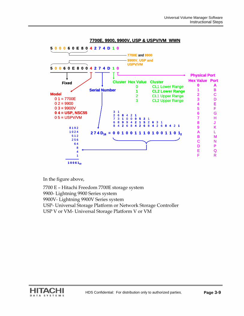
Universal Volume Manager Software Instructional Steps
HDS Confidential: For distribution only to authorized parties. Page 3-9
In the figure above,
7700 E – Hitachi Freedom 7700E storage system 9900- Lightning 9900 Series system 9900V- Lightning 9900V Series system USP- Universal Storage Platform or Network Storage Controller USP V or VM- Universal Storage Platform V or VM
5 0 0 6 0 E 8 0 0 4 2 7 4 D 1 0
Model0 1 = 7700E0 2 = 99000 3 = 9900V0 4 = USP, NSC550 5 = USPV/VM
Serial Number
2 7 4 D16 = 0 0 1 0 0 1 1 1 0 1 0 0 1 1 0 12
124816
32
64
128
256
512
1024
2048
4096
16384
32768
8192
8 1 9 21 0 2 4
5 1 22 5 6
6 4841
1 0 0 6 110
Cluster Hex Value Cluster0 CL1 Lower Range1 CL2 Lower Range2 CL1 Upper Range3 CL2 Upper Range
Physical PortHex Value Port
0 A1 B2 C3 D4 E5 F6 G7 H8 J9 KA LB MC ND PE QF R
Fixed
7700E, 9900, 9900V, USP & USPV/VM WWN
5 0 0 0 6 0 E 8 0 4 2 7 4 D 1 0
9900V, USP and USPV/VM
7700E and 9900

Universal Volume Manager Software Instructional Steps
Page 3-10 HDS Confidential: For distribution only to authorized parties.
In the figure above, AMS is Adaptable Modular Storage and WMS is Workgroup Modular Storage
In the figure above:
9200 is Thunder 9200 system 9500 is Thunder 9500V Series system
Physical Port
AMS200 & WMS1000 – Controller 0 Port 0A1 – Controller 1 Port 1A
AMS500 or AMS200 or WMS100 with the dual-port daughter board0 – Controller 0 Port 0A1 – Controller 0 Port 0B2 – Controller 1 Port 1A3 – Controller 1 Port 1B
AMS10000 – Controller 0 Port 0A1 – Controller 0 Port 0B2 – Controller 0 Port 0C3 – Controller 0 Port 0D4 – Controller 1 Port 1A5 – Controller 1 Port 1B6 – Controller 1 Port 1C7 – Controller 1 Port 1D
5 0 0 6 0 E 8 0 1 0 6 2 9 4 8 0
Serial NumberIn Hexadecimal
Fixed
Model0 = AMS10002 = AMS5004 = AMS2006 = WMS100
HDS Part NumberThe first three digits identify the model, the last five digits the Serial Number:
710XXXXX = WMS100730XXXXX = AMS200 For Example: 71010568750XXXXX = AMS500770XXXXX = AMS1000
WWN
WMS & AMS WWN
9200 and 9500V WWN
5 0 0 6 0 E 8 0 0 0 4 4 2 9 E 0
Serial NumberIn Hexadecimal
Physical Port
9200 and 95X0V0 – Controller 0 Port A1 – Controller 0 Port B2 – Controller 1 Port A3 – Controller 1 Port B
9580V and 9585V0 – Controller 0 Port A1 – Controller 0 Port B2 – Controller 0 Port C3 – Controller 0 Port D4 – Controller 1 Port A5 – Controller 1 Port B6 – Controller 1 Port C7 – Controller 1 Port D
Fixed
Model0 = 92004 = 9500VC = 9580V

Universal Volume Manager Software Instructional Steps
HDS Confidential: For distribution only to authorized parties. Page 3-11
Question 3: With two WWNs you have discovered, identify the model, serial number of the device, the Cluster or Controller, and port number of the connections.
___________________________________________________________________
Map External LUNs to Universal Storage Platform V or VM Internal LDEVs
After the external LUNs are discovered, they must be mapped to internal Universal Storage Platform V or VM logical devices (LDEVs).
Only one external volume can be mapped as one internal volume.
When an external volume is mapped to an internal volume, it must be registered to an External Volume Group (ExG). As the registration is made, several external volume attributes must also be considered:
1. Select a Control Unit (CU) where you want the volume to reside and assign a LDEV number to the volume.
2. Assign an arbitrary identifying number to the External Volume Group.
3. Select OPEN-V as the emulation for the external volume regardless of the setting at the external device.
4. Select either Disable or Enable for the Cache Mode attribute, where, Disable: After receiving the data into the local storage system cache memory, the local storage system signals the host that an I/O operation has completed and then asynchronously destages the data to the external storage system.
Enable: The local storage system signals the host that an I/O operation has completed only after the local storage system has synchronously written the data to the external storage system.
5. Select either Disable or Enable for the Inflow Control attribute, where, Disable: The I/O from the host during the retry operation is written to the cache memory even after the write operation to the external volume is impossible. Once the writing operation to the external volume becomes normal, all the data in the cache memory is written to the external volume (all the data is destaged).
Enable: Access the writing operation to cache is stopped and the I/O from the host is not accepted when the writing operation to the external volume is impossible.
The external volume to internal LDEV mapping can be performed on a single volume or groups of volumes.

Universal Volume Manager Software Instructional Steps
Page 3-12 HDS Confidential: For distribution only to authorized parties.
6. Click OK to see the Add Volume screen:
These are the five LUNs being supplied by the 9970 Series system.
7. Now select all of the volumes, so you can specify the External Volume parameters. After selecting all of the volumes, right-click and select Set External Volume Parameter.

Universal Volume Manager Software Instructional Steps
HDS Confidential: For distribution only to authorized parties. Page 3-13
8. Type 100 for the external group number (ExG) and accept the defaults as shown. Click OK.
9. On return to the Add Volume window, right-click again and select LDEV Mapping (Manual).

Universal Volume Manager Software Instructional Steps
Page 3-14 HDS Confidential: For distribution only to authorized parties.
10. In the left panel select all of the devices in the E100 group. On the right select CU 06 and LDEV 00.
Note: If an SSID needs to be assigned to the selected CU, then the SSID window would appear and you can assign an SSID.

Universal Volume Manager Software Instructional Steps
HDS Confidential: For distribution only to authorized parties. Page 3-15
11. Click OK. All five LDEVS are mapped starting at 00.
12. Click Apply and then select Path Group 0. The results are as shown:

Universal Volume Manager Software Part 2: Answers to Embedded Questions
Page 3-16 HDS Confidential: For distribution only to authorized parties.
Part 2: Answers to Embedded Questions
Question 1: Why is a second port, for example: CL1-A (CL5-A), listed in parenthesis in the above screen shot?
Answer: Both ports Cl1-A and CL5-A share the same microprocessor (MP).
Question 2: Why are two WWNs listed?
Answer: There are two paths connected to two ports (WWN's) on the external device.
Question 3: With two WWNs you have discovered, identify the model, serial number of the device, the Cluster or Controller, and port number of the connections.
Answer: Answers will vary depending on the external device but for this example it is a Lightning 9900V system with ports 0A and 1A.
End of Lab

HDS Confidential: For distribution only to authorized parties. Page 4-1
Lab Activity 4 Virtual LUN (VLL)
Introduction
Lab Objectives Upon completion of the lab project, the learner should be able to:
Create six custom volumes and assign the new LDEVs
Reference Material In addition to the Student Guide, several Hitachi reference manuals are available on the desktop of each Microsoft Windows host system.
Hitachi Universal Storage Platform V or VM LUN Expansion and Virtual LVI/LUN User's Guide
Hitachi Universal Storage Platform V or VM Storage Navigator User's Guide

Virtual LUN (VLL) Instructional Steps
Page 4-2 HDS Confidential: For distribution only to authorized parties.
Instructional Steps
Create Open VLL Volumes from External Volumes In this lab project you will create six VLL volumes from the external LDEV 06:00# and then map two of these volumes to the host so that they can be used for Hitachi ShadowImage® Heterogeneous Replication software.
25GB
VLL
6 x 4GB

Virtual LUN (VLL) Instructional Steps
HDS Confidential: For distribution only to authorized parties. Page 4-3
CV Operations for OPEN-V Parity Groups The Make Volume function of OPEN-V parity groups deletes all the current fixed OPEN-V LDEVs in the parity group and allows the creation of new variable- sized CV volumes.
1. Click GO>LUN Expansion/VLL>VLL
2. Expand the External Volume Group E100-1 under the Box E100 folder in the left
navigation pane and select the E100-1(1) icon.
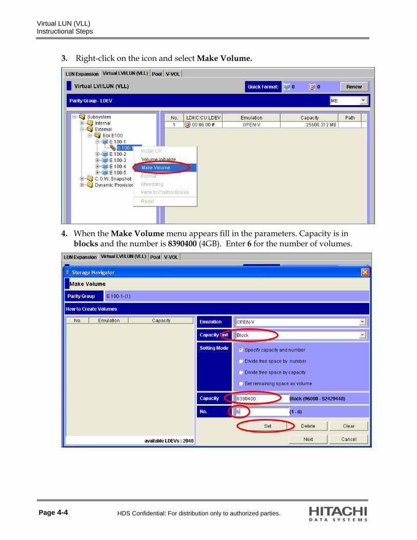
Virtual LUN (VLL) Instructional Steps
Page 4-4 HDS Confidential: For distribution only to authorized parties.
3. Right-click on the icon and select Make Volume.
4. When the Make Volume menu appears fill in the parameters. Capacity is in
blocks and the number is 8390400 (4GB). Enter 6 for the number of volumes.

Virtual LUN (VLL) Instructional Steps
HDS Confidential: For distribution only to authorized parties. Page 4-5
5. When finished, click Set. The input is represented in the left field.
6. Click Next.
7. Select CU 06 from the Select CU No. list.
8. Select the six new custom volumes and assign six consecutive LDEV numbers beginning at 5 for the six new CVs.

Virtual LUN (VLL) Instructional Steps
Page 4-6 HDS Confidential: For distribution only to authorized parties.
Note: You can select all the new CVs and then click the 5 box as a quick way to assign the numbers.
9. Click Next and then Next again.
10. Click OK, then click Apply, and then click OK to the “Do you want to apply?” prompt.
Note: The disk format operation takes a few minutes.

Virtual LUN (VLL) Instructional Steps
HDS Confidential: For distribution only to authorized parties. Page 4-7
When the devices become available go back to LUN Manager and assign two of these to the host group, winhost LUNs 4 and 5, to make them available for ShadowImage software in the next lab.
Lab End


HDS Confidential: For distribution only to authorized parties. Page 5-1
Lab Activity 5 ShadowImage Software Operations
Introduction
Lab Objectives Upon completion of the lab project, the learner should be able to:
Create a ShadowImage pair Split a ShadowImage pair putting the two volumes into suspended state Verify the data that was copied Resynchronize a suspended pair putting the volumes back into Pair status Display the command History and Pair status of a ShadowImage pair
Reference Material Several reference manuals are available on the desktop of each Microsoft Windows host system.
Universal Storage Platform V/VM Storage Navigator User’s Guide. Universal Storage Platform V/VM ShadowImage User’s Guide.

ShadowImage Software Operations Instructional Steps
Page 5-2 HDS Confidential: For distribution only to authorized parties.
Instructional Steps
Open ShadowImage Setup The Hitachi ShadowImage® Heterogeneous Replication software is a storage-based hardware solution for duplicating logical volumes that reduces backup time and provides continuous point-in-time copies. The primary volume (P-VOL) contains the original data; the secondary volume (S-VOL) contains the duplicate data.
Since each S-VOL is paired with its P-VOL independently, each S-VOL can be maintained as an independent copy set (pair) that can be split, suspended, resynchronized, and deleted separately from the other S-VOLs assigned to the same P-VOL.
Before you can use devices as open ShadowImage volumes (either P-VOLs or S-VOLs), you must map them to the desired ports of the storage system. In the previous lab the external devices were mapped as shown. For this lab we will be using CL1-A, LUN 0 (00:01:00) as the P-VOL and CL1-A, LUN 4 (00:06:05#) as the S-VOL.
In addition, you must logon to the Windows workstation and rescan (or reboot if necessary) in order to discover the new drives on the host.

ShadowImage Software Operations Instructional Steps
HDS Confidential: For distribution only to authorized parties. Page 5-3
Shadow Image Operations for OPEN-V Parity Groups The Paircreate function of ShadowImage will start the initial copy of the P-VOL to S-VOL
1. Click GO> ShadowImage> Pair Operation
2. Select port CL1-A.
3. Right-click on LUN 000 and select Paircreate.

ShadowImage Software Operations Instructional Steps
Page 5-4 HDS Confidential: For distribution only to authorized parties.
4. When the Paircreate screen appears select LUN 004 as the S-VOL.
5. Click Set.
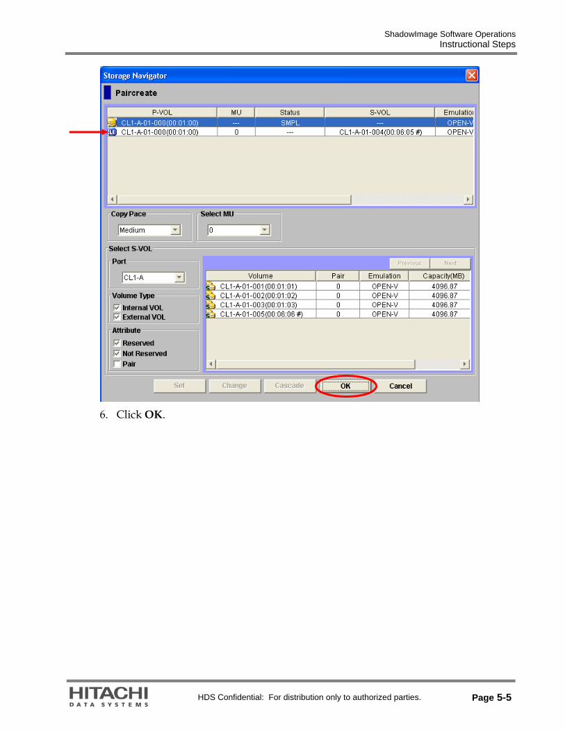
ShadowImage Software Operations Instructional Steps
HDS Confidential: For distribution only to authorized parties. Page 5-5
6. Click OK.

ShadowImage Software Operations Instructional Steps
Page 5-6 HDS Confidential: For distribution only to authorized parties.
7. Click Apply.
8. The volume changes to COPY(PD) status. To check progress, right-click on the
device and select the Detail command.
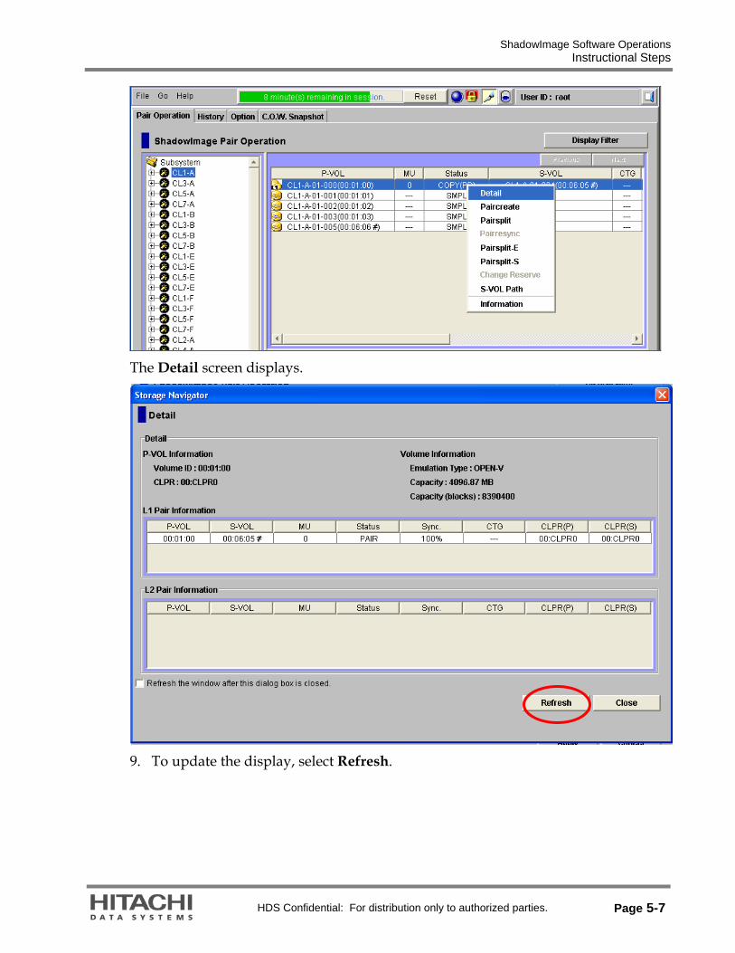
ShadowImage Software Operations Instructional Steps
HDS Confidential: For distribution only to authorized parties. Page 5-7
The Detail screen displays.
9. To update the display, select Refresh.
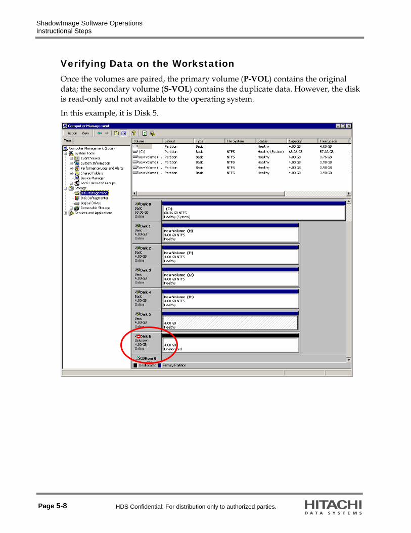
ShadowImage Software Operations Instructional Steps
Page 5-8 HDS Confidential: For distribution only to authorized parties.
Verifying Data on the Workstation Once the volumes are paired, the primary volume (P-VOL) contains the original data; the secondary volume (S-VOL) contains the duplicate data. However, the disk is read-only and not available to the operating system.
In this example, it is Disk 5.

ShadowImage Software Operations Instructional Steps
HDS Confidential: For distribution only to authorized parties. Page 5-9
1. To access any data on the S-VOL, issue the Pairsplit command to suspend the volumes. Click OK and then click Apply.

ShadowImage Software Operations Instructional Steps
Page 5-10 HDS Confidential: For distribution only to authorized parties.
2. Once this has completed, go to the workstation, rescan the disks (you might have to assign a drive letter and reboot) and verify that the P-VOL (DISK1) and the S-VOL (DISK5) contain the same data. This is the data that was copied in the previous lab project.

ShadowImage Software Operations Instructional Steps
HDS Confidential: For distribution only to authorized parties. Page 5-11
3. Issue the Pairresync command to restore the volume back in the Pair status and then check the History tab
History
End of Lab


HDS Confidential: For distribution only to authorized parties. Page 6-1
Lab Activity 6 Dynamic Provisioning Software
Overview
Lab Objectives Upon completion of the lab project, the learner should be able to:
Prepare the Universal Storage Platform V to perform Dynamic Provisioning Use Dynamic Provisioning software to make a Pool Associate a Pool Volume (Pool-VOL) to the Pool Assign a virtual volume (V-VOL) Associate a V-VOL to a Pool Set Pool thresholds
Reference Material In addition to the Student Guide, several Hitachi reference manuals are available on the desktop of each Microsoft Windows host system.
Hitachi Universal Storage Platform V/VM Storage Navigator User's Guide Hitachi Universal Storage Platform V/VM Dynamic Provisioning User’s Guide

Dynamic Provisioning Software Overview
Page 6-2 HDS Confidential: For distribution only to authorized parties.
Pre-Procedures Verify that the storage system has enough shared memory installed and the Dynamic Provisioning license key has been installed.
Note: Before you can use Dynamic Provisioning software, you must have a V-VOL management table, that is used to associate V-VOLs (Virtual Volumes) to a pool. The V-VOL management table is created automatically when the required additional shared memory is installed.
V-Vols
A
C
B
PoolHost
Pool
V-VOL Manage
ment Area Pool-VOL
Pool-VOL
A
B
C
Examples : access
: associating between V-VOL and pool : flow of data
n : data ( n : A, B, C)
The process involves the following steps:
1. Create a Pool and add Pool Volumes (real LDEVs).
2. Create the V-VOLs.
3. Associate five V-VOLs with a Pool.
4. Define the path definition for the V-VOLs.

Dynamic Provisioning Software Part 1: Instructional Steps
HDS Confidential: For distribution only to authorized parties. Page 6-3
Part 1: Instructional Steps 1. Start Hitachi Storage Navigator program and select Modify mode.
2. Click Go > LUN Expansion/VLL > Pool.
Create a New Pool 3. In the Pool pane on the left under Subsystem, right-click Dynamic Provisioning.
4. Select New Pool from the pop-up menu.

Dynamic Provisioning Software Part 1: Instructional Steps
Page 6-4 HDS Confidential: For distribution only to authorized parties.
5. Enter the Pool ID of 10 and Threshold of 5 %. Click Set.
Add Pool Volumes to the Pool 1. Select the appropriate LDKC 00 , CU 00 and LDEV 00 to create a 401GB pool.
2. Click the Add Pool-VOL button and click Apply and then OK.

Dynamic Provisioning Software Part 1: Instructional Steps
HDS Confidential: For distribution only to authorized parties. Page 6-5
Create the V-VOLs 1. Click the V-VOL tab.
2. Under the V-VOL tree, right-click Dynamic Provisioning.
3. From the pop-up menu, select New V-VOL Group. This group is a virtual parity
group and behaves like an actual parity group.
4. For V-VOL Group, enter a V-VOL Group number 1.
5. For Emulation Type, select OPEN-V and for CLPR, select CLPR0.
6. For Copy of V-VOL Groups, select the default 0. Click Next.

Dynamic Provisioning Software Part 1: Instructional Steps
Page 6-6 HDS Confidential: For distribution only to authorized parties.
Create the V-VOLs within this Group
7. For Emulation Type, select OPEN-V.
8. Select the size and number of the V-VOLs – 5 x 20GB.
9. Click Set.
10. Click Next.

Dynamic Provisioning Software Part 1: Instructional Steps
HDS Confidential: For distribution only to authorized parties. Page 6-7
Assign LDKC:CU:LDEV Numbers to the New V-VOLs
1. Select the volume in the V-VOL information setting list.
2. Select LDKC No. as 0. Select CU No. as 01. Assign the LDEVs, 30-34.
3. Click Next. Click OK and then click Apply.
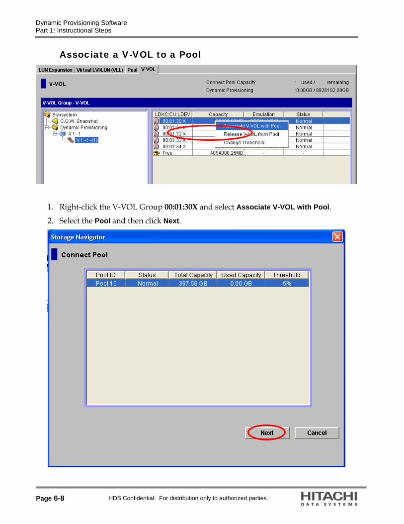
Dynamic Provisioning Software Part 1: Instructional Steps
Page 6-8 HDS Confidential: For distribution only to authorized parties.
Associate a V-VOL to a Pool
1. Right-click the V-VOL Group 00:01:30X and select Associate V-VOL with Pool.
2. Select the Pool and then click Next.

Dynamic Provisioning Software Part 1: Instructional Steps
HDS Confidential: For distribution only to authorized parties. Page 6-9
3. Set the threshold for this V-VOL to 5%.
Present to a Host and Generate Overflow The V-VOL can be presented to the Host in the same way that any other LDEV would be. Map the V-VOL into your Microsoft Windows host group, partition it and send data to it. If you send enough data to it you should be able to see the overflow SIM message generated.
To see the SIM details, Go > System Information > Status tab and right-click on the Not Complete 620000 SIM.

Dynamic Provisioning Software Part 1: Instructional Steps
Page 6-10 HDS Confidential: For distribution only to authorized parties.
This ends the guided portion of the lab project.
If you want to go back and practice what you have learned, feel free to do so. But complete the review questions before the class reconvenes for review.
Make sure you leave the system in the same state that it was in at the end of the guided portion of the lab project—this insures it will support the next lab project.
Dynamic Provisioning Software Part 2: Lab Project Review Questions
HDS Confidential: For distribution only to authorized parties. Page 6-11
Part 2: Lab Project Review Questions 1. List the components of Hitachi Dynamic Provisioning.
2. What is the maximum number of pools per subsystem?
3. What are the two types of thresholds?
4. For Best Practices you should design a few larger pools rather than multiple smaller HDP pools. True or False?
5. Hitachi Device Manager can be used to set up Hitachi Dynamic Provisioning?
True or False?
End of Lab


HDS Confidential: For distribution only to authorized parties. Page 7-1
Lab Activity 7 Virtual Partition Manager
Introduction
Objectives Upon completion of the lab project, the learner should be able to:
Create a Storage Logical Partition SLPR01 Create a Cache Logical Partition (CLPR) in the new SLPR Allocate, and/or Enable/Disable specified license keys for the new SLPR Add (migrate) specified ports to the new SLPR Allocate specified Control Units (CUs) to the new SLPR Add (migrate) specified parity groups to the CLPR Add a User ID for the new SLPR
Reference Material In addition to the Student Guide, several Hitachi reference manuals are available on the desktop of each Microsoft Windows host system.
Hitachi Universal Storage Platform V/VM Storage Navigator User's Guide Hitachi Universal Storage Platform V/VM Virtual Partition Manager User's Guide

Virtual Partition Manager Instructional Steps
Page 7-2 HDS Confidential: For distribution only to authorized parties.
Instructional Steps
Create a New Storage Logical Partition (SLPR01) 1. Start Hitachi Storage Navigator program and select Modify mode.
2. Click Go > Environmental Settings > Partition Definition.

Virtual Partition Manager Instructional Steps
HDS Confidential: For distribution only to authorized parties. Page 7-3
3. Click on SLPR0.
Note: SLPR0 (of the system used to create this lab project) contained the following pool of resources: 16GB of cache memory, 15 Parity Groups, and 32 ports (your settings may be different).
4. Right-click on the Subsystem folder in the left pane and select Create SLPR.

Virtual Partition Manager Instructional Steps
Page 7-4 HDS Confidential: For distribution only to authorized parties.
5. Click Apply and then click OK to the resulting prompts.
Create a Cache Logical Partition (CLPR) in the New SLPR
In this lab project, you will create the empty CLPRs. Later you will add (migrate) resources to the SLPRs and CLPRs.
1. Right-click on SLPR01 and select Create CLPR.
2. Click on 01:CLPR1 and enter 8GB as shown:

Virtual Partition Manager Instructional Steps
HDS Confidential: For distribution only to authorized parties. Page 7-5
3. Click Apply and then click OK to the resulting prompts and the following appears:
Install License Keys for Each SLPR Next, you will allocate a section of each Hitachi product license key with a limited capacity and enable the key for the products that has unlimited capacity.
The system used to create this lab project had the following product license key capacities. Your system may have different capacities:
Table 1
Product Capacity Cache Residency Manager 100TB Data Retention Utility Not installed Open Volume Management 100TB LUN Manager 100TB Performance Monitor 100TB Storage Navigator Program 100TB JAVA API 100TB Volume Shredder 100TB

Virtual Partition Manager Instructional Steps
Page 7-6 HDS Confidential: For distribution only to authorized parties.
Using the steps following Table 2, you will configure each SLPR as follows:
Table 2
Capacity Product
SLPR0 SLPR01 Cache Residency Manager 50TB 50TB Data Retention Utility Not Installed Not Installed Open Volume Management 50TB 50TB LUN Manager 50TB 50TB Performance Monitor 50TB 50TB Storage Navigator Program 50TB 50TB JAVA API 50TB 50TB Volume Shredder 50TB 50TB
1. Click on the License Key Partition Definition tab.
2. Click on the Cache Residency Manager under Product Name column and then click on the SLPR01 in the Partition Status table.
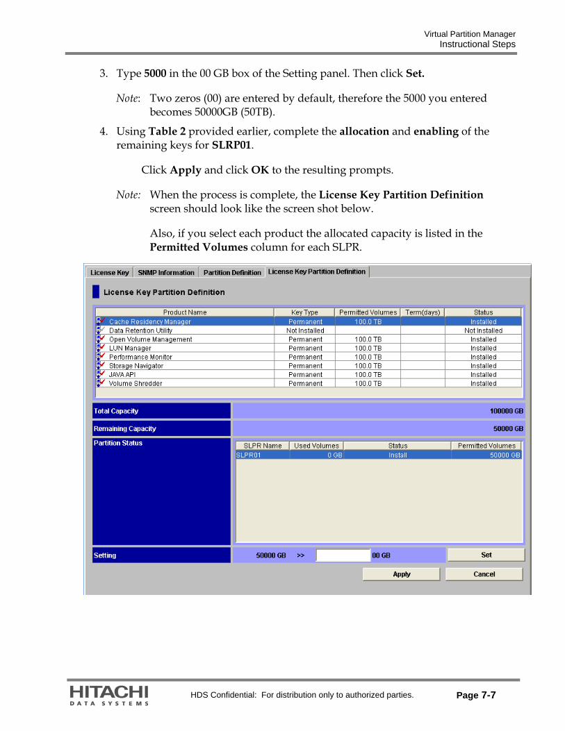
Virtual Partition Manager Instructional Steps
HDS Confidential: For distribution only to authorized parties. Page 7-7
3. Type 5000 in the 00 GB box of the Setting panel. Then click Set.
Note: Two zeros (00) are entered by default, therefore the 5000 you entered becomes 50000GB (50TB).
4. Using Table 2 provided earlier, complete the allocation and enabling of the remaining keys for SLRP01.
Click Apply and click OK to the resulting prompts.
Note: When the process is complete, the License Key Partition Definition screen should look like the screen shot below.
Also, if you select each product the allocated capacity is listed in the Permitted Volumes column for each SLPR.

Virtual Partition Manager Instructional Steps
Page 7-8 HDS Confidential: For distribution only to authorized parties.
Add a Port to SLPR01 Next, you will add (migrate) a port (CL1-A) to SLPR01.
Suspend the ShadowImage pair that you created in Lab 5 (pairsplit –S) and from the LUN Manager, un-map all the LDEVs for all ports..
1. Click the Partition Definition tab.
2. Click on SLPR0 to display the available ports.
3. Right-click on CL1-A port and then select Cut.
4. Right-click on SLPR01 and then select Paste CLPRs, Ports.
5. Click the Select CU button to map Control Unit 06 to SLPR01. Click Set.
6. Click Apply and then click OK to the resulting prompts.
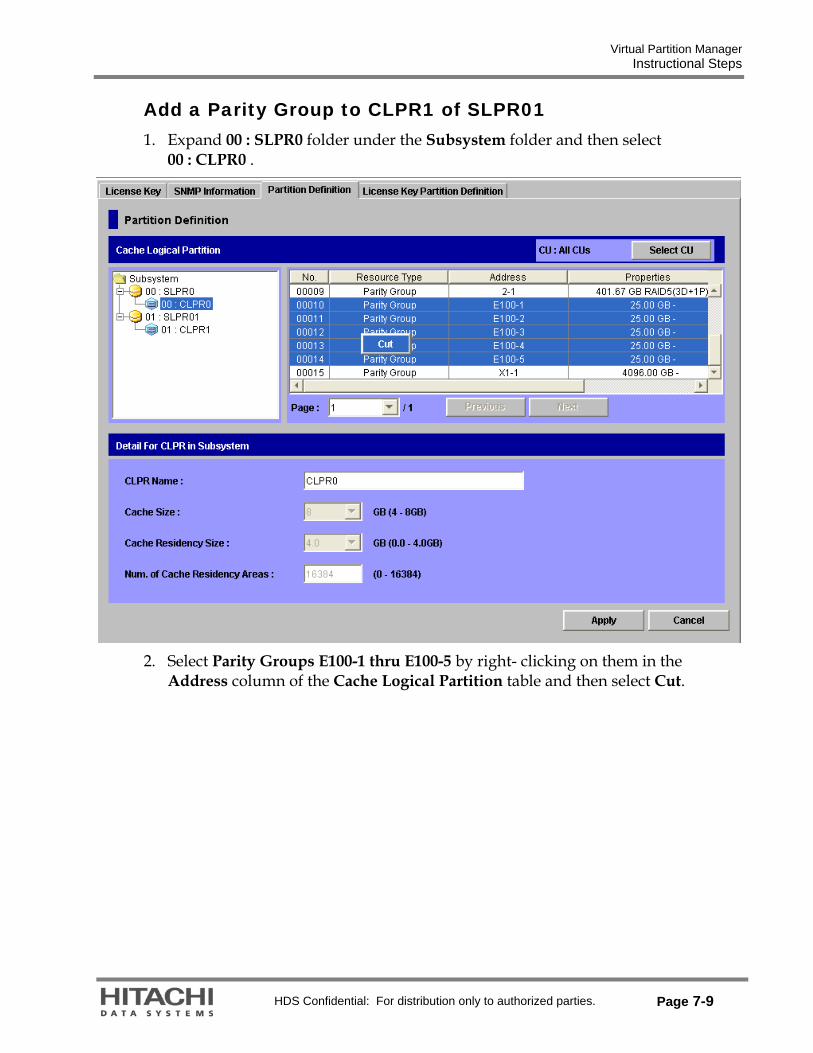
Virtual Partition Manager Instructional Steps
HDS Confidential: For distribution only to authorized parties. Page 7-9
Add a Parity Group to CLPR1 of SLPR01 1. Expand 00 : SLPR0 folder under the Subsystem folder and then select
00 : CLPR0 .
2. Select Parity Groups E100-1 thru E100-5 by right- clicking on them in the
Address column of the Cache Logical Partition table and then select Cut.

Virtual Partition Manager Instructional Steps
Page 7-10 HDS Confidential: For distribution only to authorized parties.
3. Expand 01 : SLPR01 and then right-click on 01 : CLPR1 and select Paste Parity Groups.
4. Click Apply and then click OK to the resulting prompts. When the process is
complete, the Partition Definition screen should look like the following screen:

Virtual Partition Manager Instructional Steps
HDS Confidential: For distribution only to authorized parties. Page 7-11
Create a User ID for SLPR01 1. Click Go menu>Security>Account.
2. Right click 01 : SLPR01 from the Account folder and create a New User.
3. Enter the following: User ID: newslpr Password: abcdef Re-enter Password: abcdef Write Permissions: Leave all the functions in Modify mode

Virtual Partition Manager Instructional Steps
Page 7-12 HDS Confidential: For distribution only to authorized parties.
4. Apply the changes.
5. Exit the Storage Navigator program by clicking the Exit icon on the top-right of the screen.
6. Log back in as newslpr.

Virtual Partition Manager Instructional Steps
HDS Confidential: For distribution only to authorized parties. Page 7-13
7. To change to Modify mode, click the Mode Switch (ink pen) icon on the top right corner of the screen.
8. Start the LUN Manager and expand the Fibre folder. Then select the 1A-G00 host group.

Virtual Partition Manager Instructional Steps
Page 7-14 HDS Confidential: For distribution only to authorized parties.
The only available port is CL1-A port and the CU list should verify that only CU 06 is available.
End of Lab