Embed Size (px)
Citation preview

A C S E C G r o u p C o m p a n y
CHAMPAK STEEL & ENGINEERING CO .CHAMPAK STEEL & ENGINEERING CO .CHAMPAK STEEL & ENGINEERING CO .CHAMPAK STEEL & ENGINEERING CO .
www.champaksteel.com
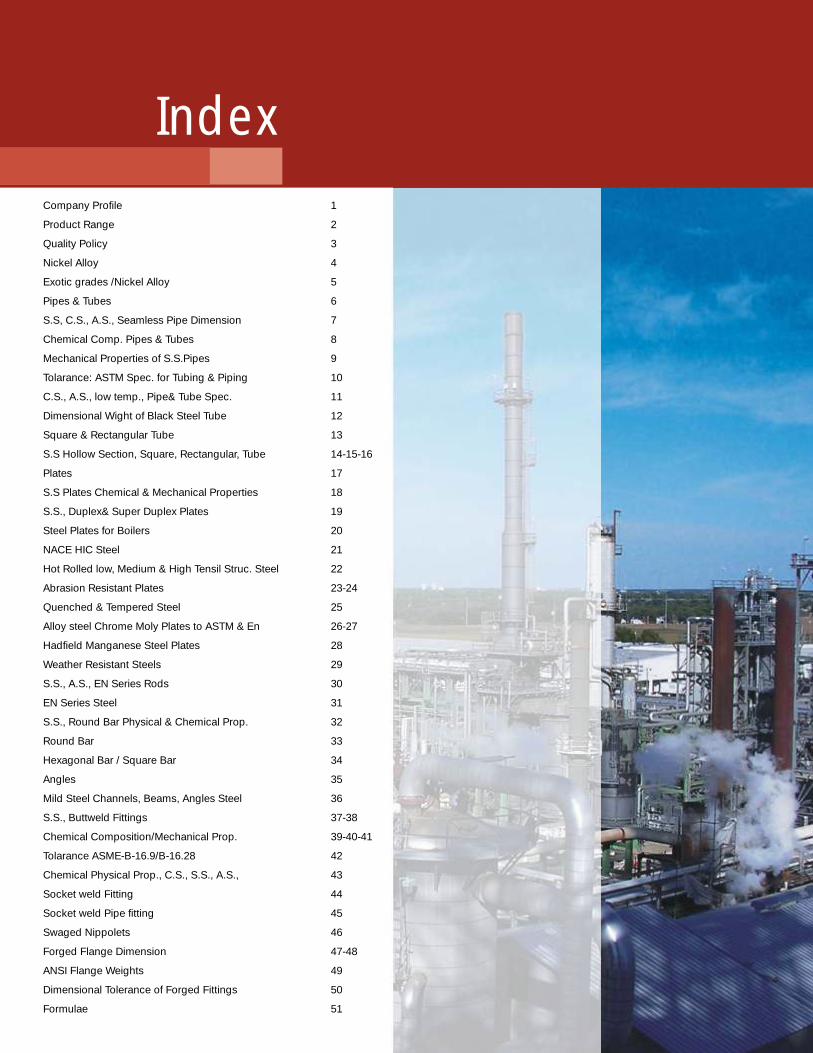
Company Profile 1
Product Range 2
Quality Policy 3
4
5
6
S.S, C.S., A.S., Seamless Pipe Dimension 7
8
9
10
11
12
13
16
17
18
19
20
21
22
24
25
27
28
29
30
31
32
33
34
35
36
38
41
42
43
44
45
46
48
49
50
Formulae 51
Nickel Alloy
Exotic grades /Nickel Alloy
Pipes & Tubes
Chemical Comp. Pipes & Tubes
Mechanical Properties of S.S.Pipes
Tolarance: ASTM Spec. for Tubing & Piping
C.S., A.S., low temp., Pipe& Tube Spec.
Dimensional Wight of Black Steel Tube
Square & Rectangular Tube
S.S Hollow Section, Square, Rectangular, Tube 14-15-
Plates
S.S Plates Chemical & Mechanical Properties
S.S., Duplex& Super Duplex Plates
Steel Plates for Boilers
NACE HIC Steel
Hot Rolled low, Medium & High Tensil Struc. Steel
Abrasion Resistant Plates 23-
Quenched & Tempered Steel
Alloy steel Chrome Moly Plates to ASTM & En 26-
Hadfield Manganese Steel Plates
Weather Resistant Steels
S.S., A.S., EN Series Rods
EN Series Steel
S.S., Round Bar Physical & Chemical Prop.
Round Bar
Hexagonal Bar / Square Bar
Angles
Mild Steel Channels, Beams, Angles Steel
S.S., Buttweld Fittings 37-
Chemical Composition/Mechanical Prop. 39-40-
Tolarance ASME-B-16.9/B-16.28
Chemical Physical Prop., C.S., S.S., A.S.,
Socket weld Fitting
Socket weld Pipe fitting
Swaged Nippolets
Forged Flange Dimension 47-
ANSI Flange Weights
Dimensional Tolerance of Forged Fittings
Index
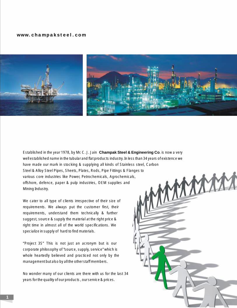
Established in the year by Mr. C. J. Jain Champak Steel & Engineering Co. is now a very
well established name in the tubular and flat products industry. In less than 34 years of existence we
have made our mark in stocking & supplying all kinds of Stainless steel, Carbon
Steel & Alloy Steel Pipes, Sheets, Plates, Rods, Pipe Fittings & Flanges to
various core industries like Power, Petrochemicals, Agrochemicals,
offshore, defence, paper & pulp industries, OEM supplies and
Mining Industry.
We cater to all type of clients irrespective of their size of
requirements. We always put the customer first, their
requirements, understand them technically & further
suggest, source & supply the material at the right price &
right time in almost all of the world specifications. We
specialize in supply of hard to find materials.
“Project 3S” This is not just an acronym but is our
corporate philosophy of "source, supply, service" which is
whole heartedly believed and practiced not only by the
management but also by all the other staff members.
No wonder many of our clients are there with us for the last 34
years for the quality of our products , our service & prices.
1978,
w w w . c h a m p a k s t e e l . c o m
1
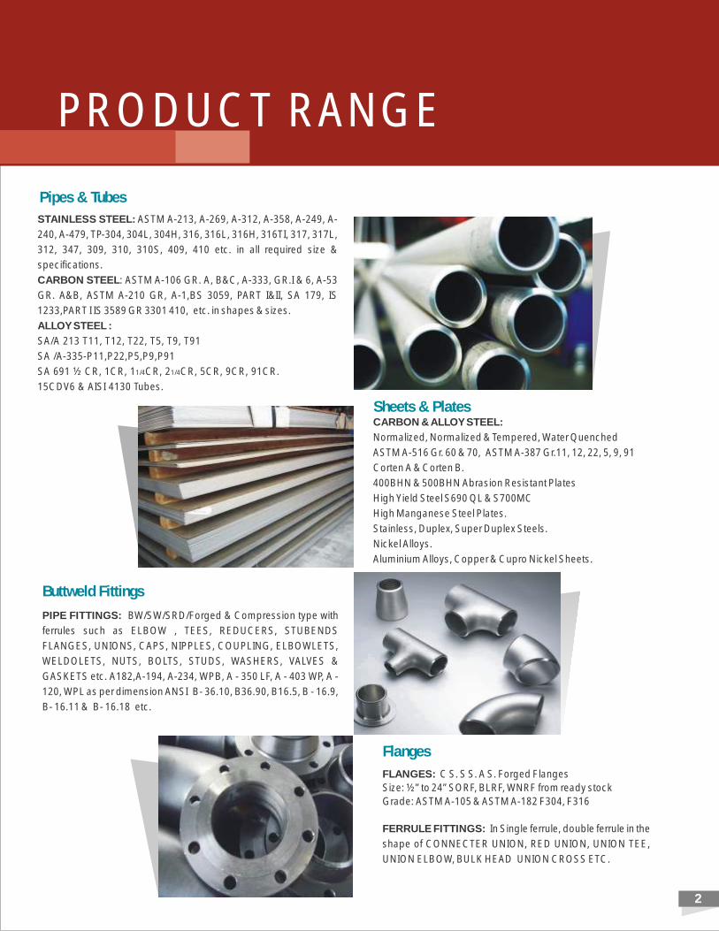
STAINLESS STEEL: ASTM A-213, A-269, A-312, A-358, A-249, A-
240, A-479, TP-304, 304L, 304H, 316, 316L, 316H, 316TI, 317, 317L,
312, 347, 309, 310, 310S, 409, 410 etc. in all required size &
specifications.
CARBON STEEL: ASTM A-106 GR. A, B&C, A-333, GR.I & 6, A-53
GR. A&B, ASTM A-210 GR, A-1,BS 3059, PART I&II, SA 179, IS
1233,PART I IS 3589 GR 3301 410, etc. in shapes & sizes.
ALLOY STEEL :
SA/A 213 T11, T12, T22, T5, T9, T91
SA /A-335-P11,P22,P5,P9,P91
SA 691 ½ CR, 1CR, 11/4CR, 21/4CR, 5CR, 9CR, 91CR.
15CDV6 & AISI 4130 Tubes.
CARBON & ALLOY STEEL:
Normalized, Normalized & Tempered, Water Quenched
ASTM A-516 Gr. 60 & 70, ASTM A-387 Gr.11, 12, 22, 5, 9, 91
Corten A & Corten B.
400BHN & 500BHN Abrasion Resistant Plates
High Yield Steel S690 QL & S700MC
High Manganese Steel Plates.
Stainless, Duplex, Super Duplex Steels.
Nickel Alloys.
Aluminium Alloys, Copper & Cupro Nickel Sheets.
PIPE FITTINGS: BW/SW/SRD/Forged & Compression type with
ferrules such as ELBOW , TEES, REDUCERS, STUBENDS
FLANGES, UNIONS, CAPS, NIPPLES, COUPLING, ELBOWLETS,
WELDOLETS, NUTS, BOLTS, STUDS, WASHERS, VALVES &
GASKETS etc. A182,A-194, A-234, WPB, A - 350 LF, A - 403 WP, A -
120, WPL as per dimension ANSI B- 36.10, B36.90, B16.5, B - 16.9,
B- 16.11 & B- 16.18 etc.
FLANGES: C S. S S. A S. Forged Flanges
Size: ½” to 24” SORF, BLRF, WNRF from ready stock
Grade: ASTM A-105 & ASTM A-182 F304, F316
FERRULE FITTINGS: In Single ferrule, double ferrule in the
shape of CONNECTER UNION, RED UNION, UNION TEE,
UNION ELBOW, BULK HEAD UNION CROSS ETC.
Sheets & Plates
Flanges
2
Pipes & Tubes
Buttweld Fittings
PRODUCT RANGE
w w w . c h a m p a k s t e e l . c o m
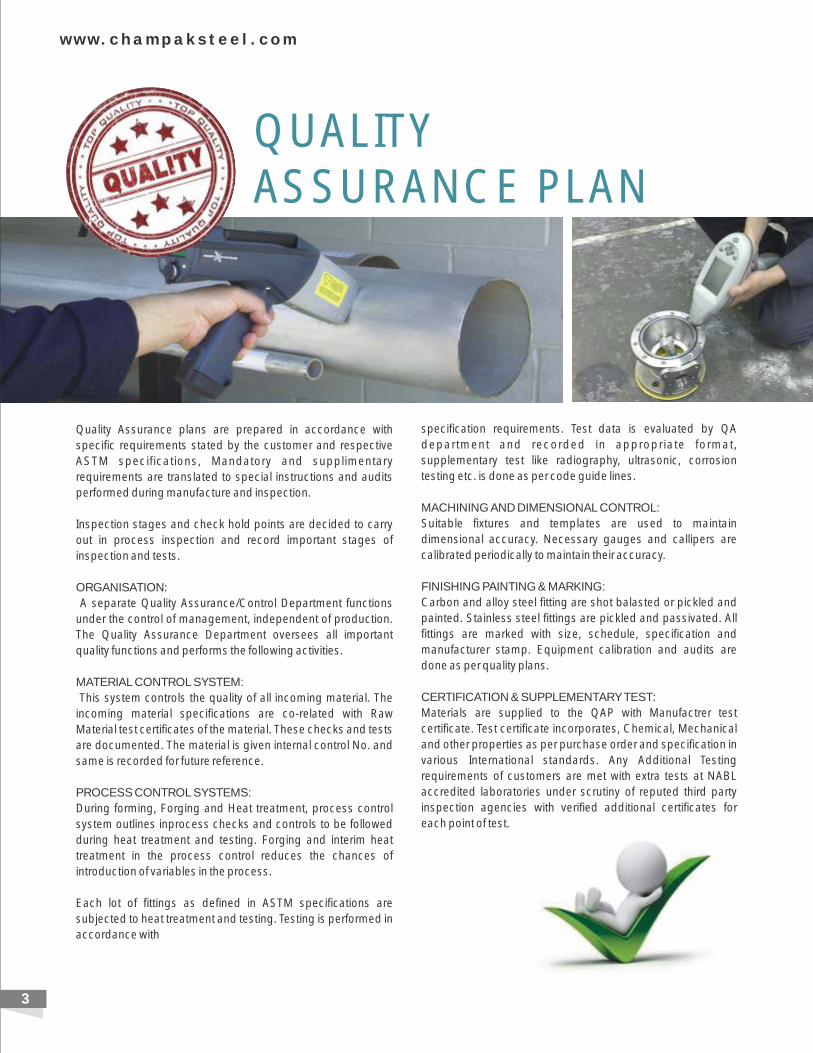
Quality Assurance plans are prepared in accordance with
specific requirements stated by the customer and respective
ASTM specifications, Mandatory and supplimentary
requirements are translated to special instructions and audits
performed during manufacture and inspection.
Inspection stages and check hold points are decided to carry
out in process inspection and record important stages of
inspection and tests.
ORGANISATION:
A separate Quality Assurance/Control Department functions
under the control of management, independent of production.
The Quality Assurance Department oversees all important
quality functions and performs the following activities.
MATERIAL CONTROL SYSTEM:
This system controls the quality of all incoming material. The
incoming material specifications are co-related with Raw
Material test certificates of the material. These checks and tests
are documented. The material is given internal control No. and
same is recorded for future reference.
PROCESS CONTROL SYSTEMS:
During forming, Forging and Heat treatment, process control
system outlines inprocess checks and controls to be followed
during heat treatment and testing. Forging and interim heat
treatment in the process control reduces the chances of
introduction of variables in the process.
Each lot of fittings as defined in ASTM specifications are
subjected to heat treatment and testing. Testing is performed in
accordance with
specification requirements. Test data is evaluated by QA
department and recorded in appropriate format,
supplementary test like radiography, ultrasonic, corrosion
testing etc. is done as per code guide lines.
MACHINING AND DIMENSIONAL CONTROL:
Suitable fixtures and templates are used to maintain
dimensional accuracy. Necessary gauges and callipers are
calibrated periodically to maintain their accuracy.
FINISHING PAINTING & MARKING:
Carbon and alloy steel fitting are shot balasted or pickled and
painted. Stainless steel fittings are pickled and passivated. All
fittings are marked with size, schedule, specification and
manufacturer stamp. Equipment calibration and audits are
done as per quality plans.
CERTIFICATION & SUPPLEMENTARY TEST:
Materials are supplied to the QAP with Manufactrer test
certificate. Test certificate incorporates, Chemical, Mechanical
and other properties as per purchase order and specification in
various International standards. Any Additional Testing
requirements of customers are met with extra tests at NABL
accredited laboratories under scrutiny of reputed third party
inspection agencies with verified additional certificates for
each point of test.
QUALITYASSURANCE PLAN
3
4
NICKEL 200 / 201Commercial pure nickel with good mechanical properties and excellent resistance to to may corrosive media. Important characteristic are its magnetic and magnetostrictive properties, the high thermal and electrical conductivity at low gas content.
MONEL 400 (ALLOY 400)Alloy 400 is especially resistant to salino and other acids in ventilated condition. It is successfully employed in the salt winning process. Alloy 400 is especially suited for employment in sea breakage water at high speed, where resistance against cavitation and erosion is of great importance. This alloy is very resistant to solvents, glass etching agents. sulphuric and other acids and virtually to all alkalis. This grade is not
0sensitive to stress corrosion cracking in oxidizing media. Alloy 400 can be employed at temperatures up to 550 Celsius.
MONEL K-500 (ALLOY K-500)An age-hardening alloy with the same corrosion resistance as Alloy 400, though with increased tensile strenght and hardness. Alloy K-500
oretains its strength up to temperature of about 650 Celsius.
INCONEL 600 (ALLOY 600)oAlloy 600 has excellent resistance to oxidation at temperatures upto 1175 Celsius and is also resistant to a variaty of corrosive media. It
0retains its high strength up to about 650 Celsius. Even at lowest temperature, alloy 600 is employed in components of power plants. This grade can be welded without thermal retreatment.
INCONEL 625 (ALLOY 625)o o Excellent corrosion resistance with high strength and ductility at temperature upto 700 Celsius applicable upto 1100 Celsius. Alloy 625 is
weldable without thermal retreatment.
INCOLLOY 800 (H) (ALLOY 800 (H)This Alloy is resistant to corrosion resulting form hydrogen sulphide as well as to stress corrosion cracking. It is highly heat resistant and insensitive to the separation of sigma phase. Alloy 800 H with controlled carbon content improves furthermore the creep strength depending on time solution annealed condition.
INCOLLOY 825 (ALLOY 825 )Resistance to acid, phosphoric acid solvents and sea water as well as to many oxidising chemicals. Alloy 825 has good resistance to reducing acid. It can be employed without thermal treatment after the welding process.
sulphuric
HASTALLOY C-276 (ALLOY C-276)Today probably one of the best and manifold alloys on the market, when employed in extremely corrosive reducing and oxidising applications. Alloy C-276 has excellent resistance to strong oxidising media contaminated chloride, dry chloride acid formate acid. acetic hydride solutions, sea water solutions and saline solutions. The alloy is resistance to the corrosive infuence of the hydrochloride acid, hydrochloride chlorine diexide solutions.
HASTALLOY C-4 (ALLOY C-4)Excellent resistance against strong oxidising agents, hot contaminated miniral acid, solvent, chlorine and media contaminated by chlorine (organic and inorganic), dry chloric acid, formic acid, acetic hydride solutions, sea water solution and saline solution. This alloy has high
0ductility and corrosive resistance even in temperature range of 650-1040 celsius. Alloy C-4 is resistant against the formation of grain boundary carbides and can thus used in most cases without heat - treatment after welding.
INCOLLY DS (ALLOY DS)Alloy Ds is a heat resistant Ni-Cr-Fe alloy with Si addition for the employment at temperatures where sufficient strength and corrosive
0resistance are required. Alloy Ds is heat-resistant upto 1100 Celsius when in air. This alloy is especially resistant against changing oxidising 0/ reducing conditions as well as the formation of sigma phase in the critical temperature range of 590-870 Celsius. Furthermore it is green
rot. Due to high strength and heat resistance to alloy DS, smaller sections than usual can be manufactured from this material.
ALLOY20Alloy 20 is a high-alloyed stainless steel. Its corrosion properties surpass those of usual stainless qualities. For example. alloy 20 has excellent stress corrosion to boiling 20-40% sulphuric acid. Although alloy 20 was originally developed for usage in sulphuric environment, its range of application has been steadily extended and today also includes machining of artificial rubber, plastic, synthetic fiber etc. In pharmaceutical and food producing application, where purity has to be guaranteed, Alloy 20 is employed to prevent metalic contamination. The most important advantages of this grade are its excellent mechanical properties as well as its comparatively easy machine ability.
NICKEL ALLOY / Additional Services
Ag
e H
ard
en
ing
S
teels
Mart
en
sit
ic
5
NIT
RO
NIC
-4
w w w . c h a m p a k s t e e l . c o m
A C S E C G r o u p C o m p a n y
CHAMPAK STEEL & ENGINEERING CO .CHAMPAK STEEL & ENGINEERING CO .CHAMPAK STEEL & ENGINEERING CO .CHAMPAK STEEL & ENGINEERING CO .
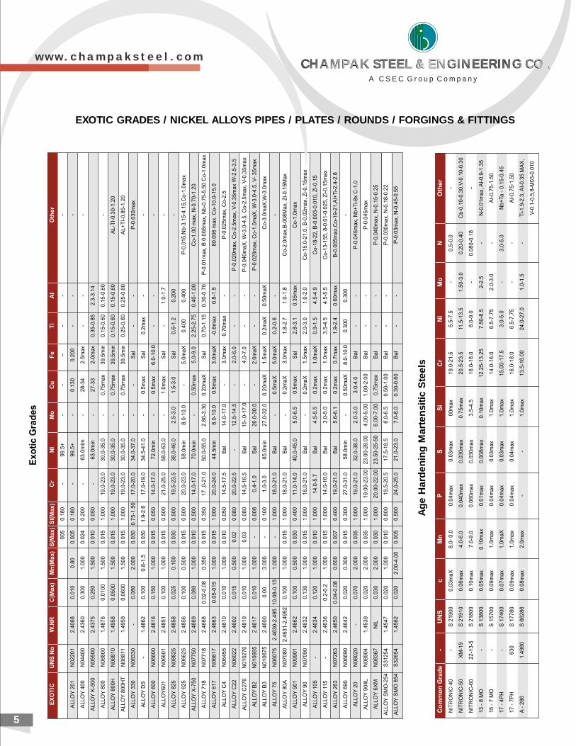
EXOTIC GRADES / NICKEL ALLOYS PIPES / PLATES / ROUNDS / FORGINGS & FITTINGS
PIPES & TUBES
w w w . c h a m p a k s t e e l . c o m 6
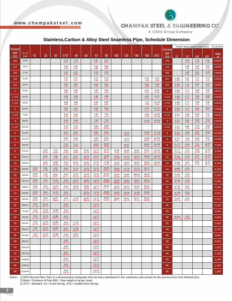
Notes : 1) NPS (Normal Piper Size) is a dimensionless designator that has been substituted in the customary units section for the previous term inch Nominal Size.2) Black- Thickness of Pipe RED - Pipe weight in kg per meter.3) STD = Standard, XS = Extra Strong, XXS = Double Extra Strong.
Stainless,Carbon & Alloy Steel Seamless Pipe, Schedule Dimension
7
SHIPPINGFIGURES BASED ON AUSTENITIC STEEL
O, Dmm 10 20 30 STD 40 60 XS 80 100 120 140 160 XXS
Nominalpipe size
1/8
1/4
3/8
1/2
3/4
1
1 1/4
1 1/2
2
2 1/2
3
3 1/2
4
5
6
8
10
12
14
16
18
20
22
24
26
28
30
32
34
36
38
40
42
44
46
48
10,30
13,70
17,10
21,30
26,70
33,40
42,20
48,30
60,30
73,00
88,90
101,60
114,30
141,30
168,30
219,10
273,10
323,90
355,60
406,40
457,00
508,00
559,00
610,00
660,00
711,00
762,00
813,00
864,00
914,00
965,00
1016,00
1067,00
1118,00
1168,00
1219,00
6,35
6,35
6,35
6,35
6,35
6,35
7,92
7,92
7,92
7,92
7,92
7,92
54,69
62,64
70,57
78,55
86,54
94,53
127,36
137,32
147,28
157,24
167,20
176,96
6,35
6,35
6,35
7,92
7,92
7,92
9,53
9,53
9,53
12,70
12,70
12,70
12,70
12,70
12,70
33,31
41,77
49,73
67,90
77,83
87,71
117,15
129,13
141,12
202,72
218,69
234,67
250,64
266,61
282,27
7,04
7,80
8,38
9,53
9,53
11,13
12,70
12,70
14,27
--
15,88
15,88
15,88
15,88
15,88
36,81
51,03
65,20
81,33
93,27
122,38
155,12
171,09
209,64
271,21
292,18
312,15
332,12
351,70
1,73
2,24
2,31
2,77
2,87
3,38
3,56
3,68
3,91
5,16
5,49
5,74
6,02
6,55
7,11
8,18
9,27
9,53
9,53
9,53
9,53
9,53
9,53
9,53
9,53
9,53
9,53
9,53
9,53
9,53
9,53
9,53
9,53
9,53
9,53
9,53
0,37
0,63
0,84
1,27
1,69
2,50
3,39
4,05
5,44
8,63
11,29
13,57
16,07
21,77
28,26
42,55
60,31
73,88
81,33
93,27
105,16
117,15
129,13
141,12
152,87
164,85
176,84
188,82
200,31
212,56
224,54
236,53
248,52
260,50
272,25
284,24
1,73
2,24
2,31
2,77
2,87
3,38
3,56
3,68
3,91
5,16
5,49
5,74
6,02
6,55
7,11
8,18
9,27
10,31
11,13
12,70
14,27
15,09
--
17,48
--
--
--
17,48
17,48
19,05
0,37
0,63
0,84
1,27
1,69
2,50
3,39
4,05
5,44
8,63
11,29
13,57
16,07
21,77
28,26
42,55
60,31
79,73
94,55
123,30
155,80
183,42
255,41
342,91
364,90
420,42
10.30
12.70
14.30
15.10
16.70
19.00
20.60
22.20
24.60
53.10
81.50
109.00
126.40
160.00
206.00
248.5
294.00
355.00
2,41
3,02
3,20
3,73
3,91
4,55
4,85
5,08
5,54
7,01
7,62
8,08
8,56
9,53
10,97
12,70
12,70
12,70
12,70
12,70
12,70
12,70
12,70
12,70
12,70
12,70
12,70
12,70
12,70
12,70
12,70
12,70
12,70
12,70
12,70
12,70
0,47
0,80
1,10
1,62
2,20
3,24
4,47
5,41
7,48
11,41
15,27
18,63
22,32
30,97
42,56
64,64
81,55
97,46
107,39
123,30
139,15
155,12
171,09
187,06
202,72
218,69
234,67
250,64
266,61
282,27
298,24
314,22
330,19
346,16
351,82
377,79
2,41
3,02
3,20
3,73
3,91
4,55
4,85
5,08
5,54
7,01
7,62
8,08
8,56
9,53
10,97
12,70
15,09
17,48
19,05
21,44
23,83
26,19
28,58
30,96
0,47
0,80
1,10
1,62
2,20
3,24
4,47
5,41
7,48
11,41
15,27
18,63
22,32
30,97
42,56
64,64
96,01
132,08
158,10
203,53
254,55
311,17
373,83
442,08
15,09
18,26
21,44
23,83
26,19
29,36
32,54
34,93
38,89
75,92
114,75
159,91
194,96
245,56
309,62
381,53
451,42
547,71
11,13
12,70
14,27
18,26
21,44
25,40
27,79
30,96
34,93
38,10
41,28
46,02
28,32
40,28
54,20
90,44
133,06
186,97
224,65
286,64
363,56
441,49
527,02
640,03
20,62
25,40
28,58
31,75
363,53
39,67
44,45
47,63
52,37
100,92
155,15
208,14
253,56
333,19
408,26
508,11
600,63
720,15
4,78
5,56
6,35
6,35
7,14
8,74
9,53
11,13
13,49
15,88
18,26
23,01
28,58
33,32
35,71
40,49
45,24
50,01
53,98
59,54
--
1,95
2,90
4,24
5,61
7,25
11,11
14,92
21,35
33,54
49,11
67,56
111,27
172,33
238,76
281,70
365,35
459,37
564,81
672,26
808,22
7,47
7,82
9,09
9,70
10,15
11,07
14,02
15,24
17,12
19,05
21,95
22,23
25,40
25,40
--
2,55
3,64
5,45
7,77
9,56
13,44
20,39
27,68
41,03
57,43
79,22
107,92
155,15
186,97
1/8
1/4
3/8
1/2
3/4
1
1 1/4
1 1/2
2
2 1/2
3
3 1/2
4
5
6
8
10
12
14
16
18
20
22
24
26
28
30
32
34
36
38
40
42
44
46
48
1,65
1,65
1,65
1,65
1,65
1,65
2,11
2,11
2,11
2,11
2,77
2,77
2,77
3,40
3,96
3,96
4,19
4,19
4,78
4,78
5,54
6,35
0,82
1,04
1,33
1,68
1,95
2,24
3,77
4,60
5,29
5,96
9,67
11,55
15,09
23,08
31,89
35,06
42,41
47,77
60,46
66,57
84,16
120,72
1,24
1,65
1,65
2,11
2,11
2,77
2,77
2,77
2,77
3,05
3,05
3,05
3,05
3,40
3,40
3,76
4,19
4,57
4,78
4,78
4,78
5,54
5,54
6,35
7,92
0,28
0,51
0,64
1,01
1,31
2,13
2,76
3,17
4,01
5,36
6,59
7,55
8,52
11,82
14,13
20,37
28,34
36,73
42,14
48,26
54,36
70,00
77,06
96,37
150,36
1,73
2,24
2,31
2,77
2,87
3,38
3,56
3,68
3,91
5,16
5,49
5,74
6,02
6,55
7,11
8,18
9,27
9,53
0,36
0,64
0,86
1,30
1,71
2,55
3,46
4,13
5,54
8,81
11,52
13,84
16,40
22,20
28,83
43,39
61,52
75,32
2.41
3.02
3.20
3.73
3.91
4.55
4.85
5.08
5.54
7.01
7.62
8.08
8.56
9.53
10.97
12.70
12.70
12.70
0.48
0.82
1.12
1.65
2.24
3.29
4.56
5.51
7.63
11.64
15.59
19.01
22.77
31.59
43.42
65.95
83.19
99.43
0,0001
0,0002
0,0003
0,0004
0,0007
0,0011
0,0018
0,0023
0,0036
0,0053
0,0079
0,0103
0,0130
0,0199
0,028
0,048
0,074
0,104
0,126
0,165
0,208
0,258
0,312
0,372
0,435
0,505
0,580
0,660
0,746
0,835
0,931
1,032
1,138
1,249
1,364
1,485
Nominalpipe size 5S 10S 40S 80S
Vol/m 3m
w w w . c h a m p a k s t e e l . c o m
A C S E C G r o u p C o m p a n y
CHAMPAK STEEL & ENGINEERING CO .CHAMPAK STEEL & ENGINEERING CO .CHAMPAK STEEL & ENGINEERING CO .CHAMPAK STEEL & ENGINEERING CO .
GradeUNS
Design-ation
Carbonmax
Manga-nesemax
Sulphur
max
Phos-phorusmax
Silicon Nickel ChromiumMolyb-denum
Tita-nium
Colum-blumplus
Tantalum
Tanta-lummax
NitrogenC Vana-dium
Copper Cerlum Bom
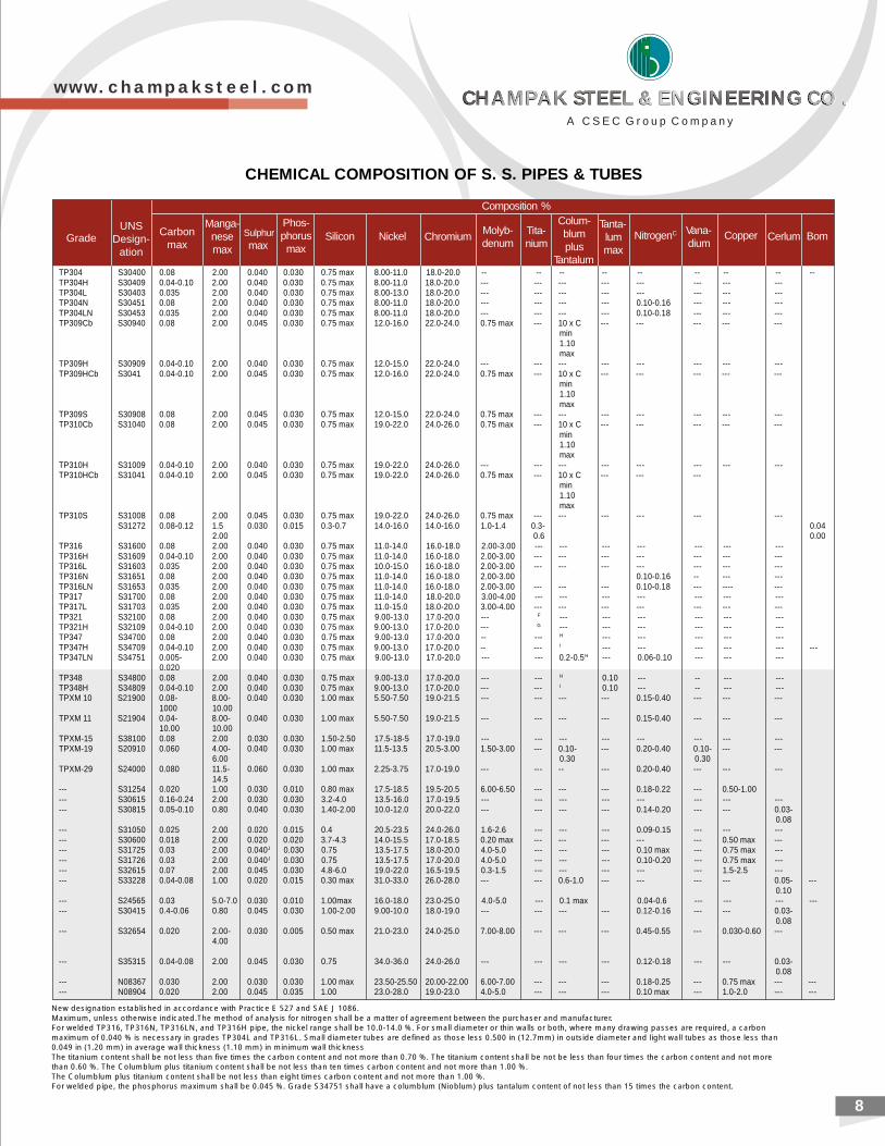
TP304 S30400 0.08 2.00 0.040 0.030 0.75 max 8.00-11.0 18.0-20.0 -- -- -- -- -- -- -- -- --TP304H S30409 0.04-0.10 2.00 0.040 0.030 0.75 max 8.00-11.0 18.0-20.0 --- --- --- --- --- --- --- ---TP304L S30403 0.035 2.00 0.040 0.030 0.75 max 8.00-13.0 18.0-20.0 --- --- --- --- --- --- --- ---TP304N S30451 0.08 2.00 0.040 0.030 0.75 max 8.00-11.0 18.0-20.0 --- --- --- --- 0.10-0.16 --- --- ---TP304LN S30453 0.035 2.00 0.040 0.030 0.75 max 8.00-11.0 18.0-20.0 --- --- --- --- 0.10-0.18 --- --- ---TP309Cb S30940 0.08 2.00 0.045 0.030 0.75 max 12.0-16.0 22.0-24.0 0.75 max --- 10 x C --- --- --- --- ---
min1.10max
TP309H S30909 0.04-0.10 2.00 0.040 0.030 0.75 max 12.0-15.0 22.0-24.0 --- --- --- --- --- --- --- ---TP309HCb S3041 0.04-0.10 2.00 0.045 0.030 0.75 max 12.0-16.0 22.0-24.0 0.75 max --- 10 x C --- --- --- --- ---
min1.10max
TP309S S30908 0.08 2.00 0.045 0.030 0.75 max 12.0-15.0 22.0-24.0 0.75 max --- --- --- --- --- --- ---TP310Cb S31040 0.08 2.00 0.045 0.030 0.75 max 19.0-22.0 24.0-26.0 0.75 max --- 10 x C --- --- --- --- ---
min1.10max
TP310H S31009 0.04-0.10 2.00 0.040 0.030 0.75 max 19.0-22.0 24.0-26.0 --- --- --- --- --- --- --- ---TP310HCb S31041 0.04-0.10 2.00 0.045 0.030 0.75 max 19.0-22.0 24.0-26.0 0.75 max --- 10 x C --- --- ---
min1.10max
TP310S S31008 0.08 2.00 0.045 0.030 0.75 max 19.0-22.0 24.0-26.0 0.75 max --- --- --- --- --- ---S31272 0.08-0.12 1.5 0.030 0.015 0.3-0.7 14.0-16.0 14.0-16.0 1.0-1.4 0.3- 0.04
2.00 0.6 0.00TP316 S31600 0.08 2.00 0.040 0.030 0.75 max 11.0-14.0 16.0-18.0 2.00-3.00 --- --- --- --- --- --- ---TP316H S31609 0.04-0.10 2.00 0.040 0.030 0.75 max 11.0-14.0 16.0-18.0 2.00-3.00 --- --- --- --- --- --- ---TP316L S31603 0.035 2.00 0.040 0.030 0.75 max 10.0-15.0 16.0-18.0 2.00-3.00 --- --- --- --- --- --- ---TP316N S31651 0.08 2.00 0.040 0.030 0.75 max 11.0-14.0 16.0-18.0 2.00-3.00 0.10-0.16 -- --- ---TP316LN S31653 0.035 2.00 0.040 0.030 0.75 max 11.0-14.0 16.0-18.0 2.00-3.00 --- --- --- 0.10-0.18 --- ---- ---TP317 S31700 0.08 2.00 0.040 0.030 0.75 max 11.0-14.0 18.0-20.0 3.00-4.00 --- --- --- --- --- --- ---TP317L S31703 0.035 2.00 0.040 0.030 0.75 max 11.0-15.0 18.0-20.0 3.00-4.00 --- --- --- --- --- --- ---TP321 S32100 0.08 2.00 0.040 0.030 0.75 max 9.00-13.0 17.0-20.0 --- F --- --- --- --- --- ---TP321H S32109 0.04-0.10 2.00 0.040 0.030 0.75 max 9.00-13.0 17.0-20.0 --- G --- --- --- --- --- ---TP347 S34700 0.08 2.00 0.040 0.030 0.75 max 9.00-13.0 17.0-20.0 -- --- H --- --- --- --- ---TP347H S34709 0.04-0.10 2.00 0.040 0.030 0.75 max 9.00-13.0 17.0-20.0 -- --- I --- --- --- --- --- ---TP347LN S34751 0.005- 2.00 0.040 0.030 0.75 max 9.00-13.0 17.0-20.0 --- --- 0.2-0.5H --- 0.06-0.10 --- --- ---
0.020TP348 S34800 0.08 2.00 0.040 0.030 0.75 max 9.00-13.0 17.0-20.0 --- --- H 0.10 --- -- --- ---TP348H S34809 0.04-0.10 2.00 0.040 0.030 0.75 max 9.00-13.0 17.0-20.0 --- --- I 0.10 --- -- --- ---TPXM 10 S21900 0.08- 8.00- 0.040 0.030 1.00 max 5.50-7.50 19.0-21.5 --- --- --- --- 0.15-0.40 --- --- ---
1000 10.00TPXM 11 S21904 0.04- 8.00- 0.040 0.030 1.00 max 5.50-7.50 19.0-21.5 --- --- --- --- 0.15-0.40 --- --- ---
10.00 10.00TPXM-15 S38100 0.08 2.00 0.030 0.030 1.50-2.50 17.5-18-5 17.0-19.0 --- --- --- --- --- --- --- ---TPXM-19 S20910 0.060 4.00- 0.040 0.030 1.00 max 11.5-13.5 20.5-3.00 1.50-3.00 --- 0.10- --- 0.20-0.40 0.10- --- ---
6.00 0.30 0.30TPXM-29 S24000 0.080 11.5- 0.060 0.030 1.00 max 2.25-3.75 17.0-19.0 --- --- -- --- 0.20-0.40 --- --- ---
14.5--- S31254 0.020 1.00 0.030 0.010 0.80 max 17.5-18.5 19.5-20.5 6.00-6.50 --- --- --- 0.18-0.22 --- 0.50-1.00--- S30615 0.16-0.24 2.00 0.030 0.030 3.2-4.0 13.5-16.0 17.0-19.5 --- --- --- --- --- --- --- ------ S30815 0.05-0.10 0.80 0.040 0.030 1.40-2.00 10.0-12.0 20.0-22.0 --- --- --- --- 0.14-0.20 --- --- 0.03-
0.08--- S31050 0.025 2.00 0.020 0.015 0.4 20.5-23.5 24.0-26.0 1.6-2.6 --- --- --- 0.09-0.15 --- --- ------ S30600 0.018 2.00 0.020 0.020 3.7-4.3 14.0-15.5 17.0-18.5 0.20 max --- --- --- --- --- 0.50 max ------ S31725 0.03 2.00 0.040J 0.030 0.75 13.5-17.5 18.0-20.0 4.0-5.0 --- --- --- 0.10 max --- 0.75 max ------ S31726 0.03 2.00 0.040J 0.030 0.75 13.5-17.5 17.0-20.0 4.0-5.0 --- --- --- 0.10-0.20 --- 0.75 max ------ S32615 0.07 2.00 0.045 0.030 4.8-6.0 19.0-22.0 16.5-19.5 0.3-1.5 --- --- --- --- --- 1.5-2.5 ------ S33228 0.04-0.08 1.00 0.020 0.015 0.30 max 31.0-33.0 26.0-28.0 --- --- 0.6-1.0 --- --- --- --- 0.05- ---
0.10--- S24565 0.03 5.0-7.0 0.030 0.010 1.00max 16.0-18.0 23.0-25.0 4.0-5.0 --- 0.1 max 0.04-0.6 --- --- --- ------ S30415 0.4-0.06 0.80 0.045 0.030 1.00-2.00 9.00-10.0 18.0-19.0 --- --- --- --- 0.12-0.16 --- --- 0.03-
0.08--- S32654 0.020 2.00- 0.030 0.005 0.50 max 21.0-23.0 24.0-25.0 7.00-8.00 --- --- --- 0.45-0.55 --- 0.030-0.60 ---
4.00
--- S35315 0.04-0.08 2.00 0.045 0.030 0.75 34.0-36.0 24.0-26.0 --- --- --- --- 0.12-0.18 --- --- 0.03-0.08
--- N08367 0.030 2.00 0.030 0.030 1.00 max 23.50-25.50 20.00-22.00 6.00-7.00 --- --- --- 0.18-0.25 --- 0.75 max --- ------ N08904 0.020 2.00 0.045 0.035 1.00 23.0-28.0 19.0-23.0 4.0-5.0 --- --- --- 0.10 max --- 1.0-2.0 --- ---
New designation established in accordance with Practice E 527 and SAE J 1086.
Maximum, unless otherwise indicated.The method of analysis for nitrogen shall be a matter of agreement between the purchaser and manufacturer.For welded TP316, TP316N, TP316LN, and TP316H pipe, the nickel range shall be 10.0-14.0 %. For small diameter or thin walls or both, where many drawing passes are required, a carbon
maximum of 0.040 % is necessary in grades TP304L and TP316L. Small diameter tubes are defined as those less 0.500 in (12.7mm) in outside diameter and light wall tubes as those less than0.049 in (1.20 mm) in average wall thickness (1.10 mm) in minimum wall thickness
The titanium content shall be not less than five times the carbon content and not more than 0.70 %. The titanium content shall be not be less than four times the carbon content and not morethan 0.60 %. The Columblum plus titanium content shall be not less than ten times carbon content and not more than 1.00 %.
The Columblum plus titanium content shall be not less than eight times carbon content and not more than 1.00 %.For welded pipe, the phosphorus maximum shall be 0.045 %. Grade S34751 shall have a columblum (Nioblum) plus tantalum content of not less than 15 times the carbon content.
Composition %
CHEMICAL COMPOSITION OF S. S. PIPES & TUBES
8
w w w . c h a m p a k s t e e l . c o m
A C S E C G r o u p C o m p a n y
CHAMPAK STEEL & ENGINEERING CO .CHAMPAK STEEL & ENGINEERING CO .CHAMPAK STEEL & ENGINEERING CO .CHAMPAK STEEL & ENGINEERING CO .
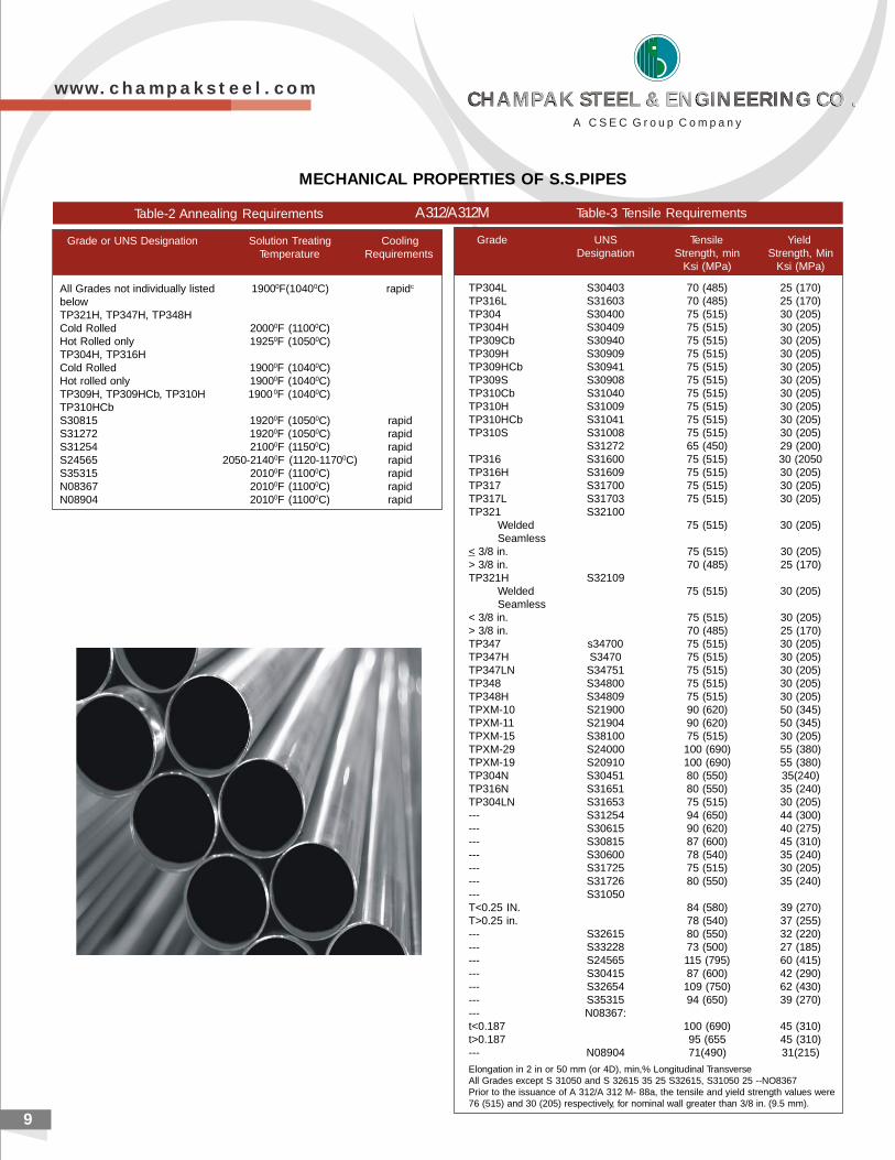
Grade UNS Tensile YieldDesignation Strength, min Strength, Min
Ksi (MPa) Ksi (MPa)
TP304L S30403 70 (485) 25 (170)TP316L S31603 70 (485) 25 (170)TP304 S30400 75 (515) 30 (205)TP304H S30409 75 (515) 30 (205)TP309Cb S30940 75 (515) 30 (205)TP309H S30909 75 (515) 30 (205)TP309HCb S30941 75 (515) 30 (205)TP309S S30908 75 (515) 30 (205)TP310Cb S31040 75 (515) 30 (205)TP310H S31009 75 (515) 30 (205)TP310HCb S31041 75 (515) 30 (205)TP310S S31008 75 (515) 30 (205)
S31272 65 (450) 29 (200)TP316 S31600 75 (515) 30 (2050TP316H S31609 75 (515) 30 (205)TP317 S31700 75 (515) 30 (205)TP317L S31703 75 (515) 30 (205)TP321 S32100
Welded 75 (515) 30 (205)Seamless
< 3/8 in. 75 (515) 30 (205)> 3/8 in. 70 (485) 25 (170)TP321H S32109
Welded 75 (515) 30 (205)Seamless
< 3/8 in. 75 (515) 30 (205)> 3/8 in. 70 (485) 25 (170)TP347 s34700 75 (515) 30 (205)TP347H S3470 75 (515) 30 (205)TP347LN S34751 75 (515) 30 (205)TP348 S34800 75 (515) 30 (205)TP348H S34809 75 (515) 30 (205)TPXM-10 S21900 90 (620) 50 (345)TPXM-11 S21904 90 (620) 50 (345)TPXM-15 S38100 75 (515) 30 (205)TPXM-29 S24000 100 (690) 55 (380)TPXM-19 S20910 100 (690) 55 (380)TP304N S30451 80 (550) 35(240)TP316N S31651 80 (550) 35 (240)TP304LN S31653 75 (515) 30 (205)--- S31254 94 (650) 44 (300)--- S30615 90 (620) 40 (275)--- S30815 87 (600) 45 (310)--- S30600 78 (540) 35 (240)--- S31725 75 (515) 30 (205)--- S31726 80 (550) 35 (240)--- S31050T<0.25 IN. 84 (580) 39 (270)T>0.25 in. 78 (540) 37 (255)--- S32615 80 (550) 32 (220)--- S33228 73 (500) 27 (185)--- S24565 115 (795) 60 (415)--- S30415 87 (600) 42 (290)--- S32654 109 (750) 62 (430)--- S35315 94 (650) 39 (270)--- N08367:t<0.187 100 (690) 45 (310)t>0.187 95 (655 45 (310)--- N08904 71(490) 31(215)
Elongation in 2 in or 50 mm (or 4D), min,% Longitudinal TransverseAll Grades except S 31050 and S 32615 35 25 S32615, S31050 25 --NO8367Prior to the issuance of A 312/A 312 M- 88a, the tensile and yield strength values were76 (515) and 30 (205) respectively, for nominal wall greater than 3/8 in. (9.5 mm).
Grade or UNS Designation Solution Treating CoolingTemperature Requirements
All Grades not individually listed 19000F(10400C) rapidc
belowTP321H, TP347H, TP348HCold Rolled 20000F (11000C)Hot Rolled only 19250F (10500C)TP304H, TP316HCold Rolled 19000F (10400C)Hot rolled only 19000F (10400C)TP309H, TP309HCb, TP310H 1900 0F (10400C)TP310HCbS30815 19200F (10500C) rapidS31272 19200F (10500C) rapidS31254 21000F (11500C) rapidS24565 2050-21400F (1120-11700C) rapidS35315 20100F (11000C) rapidN08367 20100F (11000C) rapidN08904 20100F (11000C) rapid
A 312/A 312MTable-2 Annealing Requirements Table-3 Tensile Requirements
MECHANICAL PROPERTIES OF S.S.PIPES
9
w w w . c h a m p a k s t e e l . c o m
A C S E C G r o u p C o m p a n y
CHAMPAK STEEL & ENGINEERING CO .CHAMPAK STEEL & ENGINEERING CO .CHAMPAK STEEL & ENGINEERING CO .CHAMPAK STEEL & ENGINEERING CO .
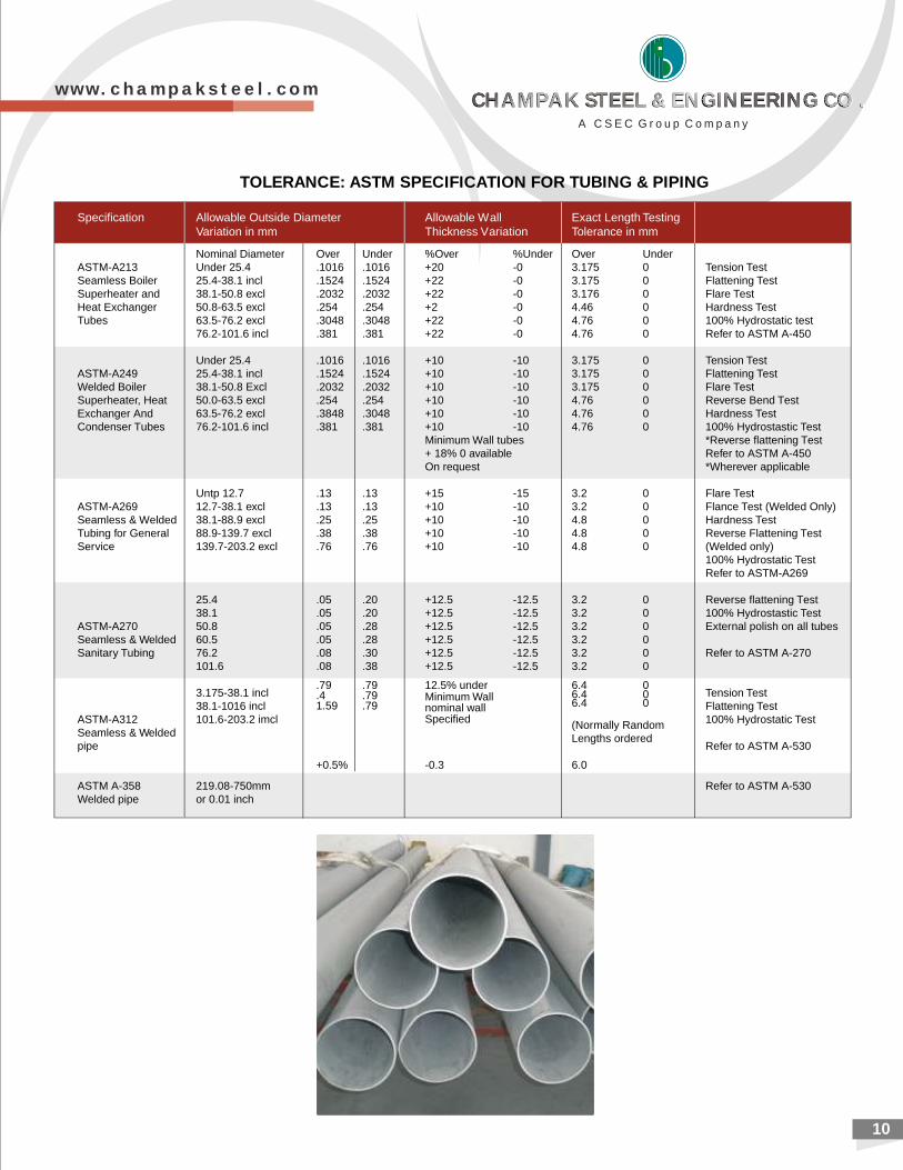
TOLERANCE: ASTM SPECIFICATION FOR TUBING & PIPING
Specification Allowable Outside Diameter Allowable Wall Exact Length TestingVariation in mm Thickness Variation Tolerance in mm
Nominal Diameter Over Under %Over %Under Over UnderASTM-A213 Under 25.4 .1016 .1016 +20 -0 3.175 0 Tension TestSeamless Boiler 25.4-38.1 incl .1524 .1524 +22 -0 3.175 0 Flattening TestSuperheater and 38.1-50.8 excl .2032 .2032 +22 -0 3.176 0 Flare TestHeat Exchanger 50.8-63.5 excl .254 .254 +2 -0 4.46 0 Hardness TestTubes 63.5-76.2 excl .3048 .3048 +22 -0 4.76 0 100% Hydrostatic test
76.2-101.6 incl .381 .381 +22 -0 4.76 0 Refer to ASTM A-450
Under 25.4 .1016 .1016 +10 -10 3.175 0 Tension TestASTM-A249 25.4-38.1 incl .1524 .1524 +10 -10 3.175 0 Flattening TestWelded Boiler 38.1-50.8 Excl .2032 .2032 +10 -10 3.175 0 Flare TestSuperheater, Heat 50.0-63.5 excl .254 .254 +10 -10 4.76 0 Reverse Bend TestExchanger And 63.5-76.2 excl .3848 .3048 +10 -10 4.76 0 Hardness TestCondenser Tubes 76.2-101.6 incl .381 .381 +10 -10 4.76 0 100% Hydrostastic Test
Minimum Wall tubes *Reverse flattening Test+ 18% 0 available Refer to ASTM A-450On request *Wherever applicable
Untp 12.7 .13 .13 +15 -15 3.2 0 Flare TestASTM-A269 12.7-38.1 excl .13 .13 +10 -10 3.2 0 Flance Test (Welded Only)Seamless & Welded 38.1-88.9 excl .25 .25 +10 -10 4.8 0 Hardness TestTubing for General 88.9-139.7 excl .38 .38 +10 -10 4.8 0 Reverse Flattening TestService 139.7-203.2 excl .76 .76 +10 -10 4.8 0 (Welded only)
100% Hydrostatic TestRefer to ASTM-A269
25.4 .05 .20 +12.5 -12.5 3.2 0 Reverse flattening Test38.1 .05 .20 +12.5 -12.5 3.2 0 100% Hydrostastic Test
ASTM-A270 50.8 .05 .28 +12.5 -12.5 3.2 0 External polish on all tubesSeamless & Welded 60.5 .05 .28 +12.5 -12.5 3.2 0Sanitary Tubing 76.2 .08 .30 +12.5 -12.5 3.2 0 Refer to ASTM A-270
101.6 .08 .38 +12.5 -12.5 3.2 0
3.175-38.1 incl .4 .79 Minimum Wall 6.4 0 Tension Test38.1-1016 incl
.79 .79 12.5% under 6.4 0
Flattening TestASTM-A312 101.6-203.2 imcl
1.59 .79 nominal wall 6.4 0
100% Hydrostatic TestSeamless & Welded
Specified
pipe
(Normally Random
Refer to ASTM A-530Lengths ordered
ASTM A-358 219.08-750mm
+0.5% -0.3 6.0
Refer to ASTM A-530Welded pipe or 0.01 inch
10
w w w . c h a m p a k s t e e l . c o m
A C S E C G r o u p C o m p a n y
CHAMPAK STEEL & ENGINEERING CO .CHAMPAK STEEL & ENGINEERING CO .CHAMPAK STEEL & ENGINEERING CO .CHAMPAK STEEL & ENGINEERING CO .
11
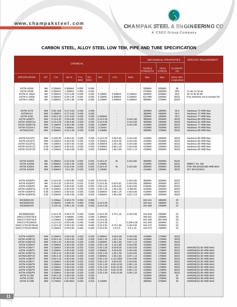
CARBON STEEL, ALLOY STEEL LOW TEM, PIPE AND TUBE SPECIFICATION
ASTM A53/A AW 0.25MAX 0.95MAX 0.050 0.045 - - - 330MIN 205MIN 36ASTM A53/B AW 0.30MAX 1.20MAX 0.050 0.045 - - - 415MIN 240MIIN 29/5 Cr Mo Cu Ni Va
ASTM /A 106/A AW 0.25MAX 0.27-0.93 0.035 0.025 0.10MIN 0.40MAX 0.15MAX 330MIN 205MIN 35/2 40 15 40 40 08ASTM A 106/B AW 0.35MAX 0.29-1.06 0.035 0.035 0.10MIN 0.40MAX 0.15MAX 415 MIN 240MIN 30/22 Five elements not to exceed 1%ASTM A 106/C AW 0.35MAX 0.29-1.06 0.035 0.035 0.10MIN 0.40MAX 0.15MAX 485MIN 275MIN 30/22
ASTM A179 MW 0.06~018 0.27-0.63 0.035 0.035 - - - 325MIN 180MIN 35.0 Hardness 72 HRB MaxASTMA214 MW 0.18MAX 0.27-0.63 0.035 0.035 - - - 385MIN 180MIN 35.0 Hardness 72 HRB MaxASTM A192 MW 0.06-0.18 0.27-0.63 0.035 0.035 0.25MAX - - 325MIN 180MIN 35.0 Hardness 77 HRB Max
ASTM a209/T1 MW 0.10-0.20 0.30-0.80 0.025 0.025 0.10-0.50 - 0.44-0.65 380MIN 205MIN 30/22 Hardness 80 HRB MaxASTM A209/T1a MW 0.15-0.25 0.30-0.80 0.025 0.025 0.10-0.50 - 0.44-0.65 365MIN 195MIN 30/22 Hardness 81 HRB MaxASTM A209/T1b MW 0.14MAX 0.30-0.80 0.025 0.025 0.10MIN - 0.44-0.65 415MIN 220MIN 30/22 Hardness 77 HRB MaxASTM A210/A-1 MW 0.27max 0.93max 0.035 0.035 0.10min - - 415MIN 255MIN 30/22 Hardness 79 HRB MaxASTMA210/C MW 0.35MAX 0.23-1.06 0.035 0.035 0.10MIN - - 485MIN 275MIN 30/22 Hardness 89 HRB Max
ASTM A213/T2 MW 0.10/0.20 0.30-0.61 0.025 0.025 0.10-0.30 0.50-0.81 0.44-0.65 415MIN 205MIN 30/22 Hardness 85 HRB MaxASTM A213/T5 MW 0.15MAX 0.30-0.60 0.025 0.025 0.50MAX 4.00-6.00 0.44-0.65 415MIN 205MIN 30/22 Hardness 85 HRB MaxASTM A213/T11 MW 0.15MAX 0.30-0.60 0.025 0.025 0.50MAX 1.00-1.50 0.44-0.65 415MIN 205MIN 30/22 Hardness 85 HRB MaxASTM A213/T12 0.05 0.15MAX 0.30-0.61 0.025 0.025 0.50MAX 0.80-1.25 0.44-0.65 415MIN 220MIN 30/22 Hardness 85 HRB MaxASTM A213/T22 0.05 0.15MAX 0.30-0.60 0.025 0.025 0.50MAX 1.90-2.60 0.87-1.13 415MIN 205MIN 30/22 Hardness 85 HRB Max
ASTM A333/3 AW 0.19MAX 0.31-0.64 0.025 0.025 0.18-0.37 Ni 3.18-3.82 380MIN 205MIN 35/25ASTM A333/6 AW 0.30MAX 0.29-1.06 0.025 0.025 0.10MIN -- - 415MIN 240MIN 30/22 IMPACT AS -50fASTM A334/3 AW 0.19MAX 0.31-0.64 0.025 0.025 0.18-0.37 Ni 3.18-3.82 380MIN 205MIN 35/28 FOR 40X10/18/1490 HRB MAXASTM A334/6 MW 0.30MAX 0.9-1.06 0.025 0.025 0.10MIN - - 415MIN 240MIN 30/22 50 f 40X10/18/14
ASTM A335/P1 AW 0.10-0.20 0.30-0.80 0.025 0.025 0.10-0.50- - 0.40-0.65 380MIN 205MIN 30/22ASTM A335/P2 AW 0.10-0.20 0.30-0.61 0.025 0.025 0.10-0.30 0.50-0.81 0.40-0.65 380MIN 205MIN 30/22ASTM A335/P5 AW 0.15MAX 0.30-0.60 0.025 0.025 0.50-1.00 4.00-6.00 0.40-0.65 415MIN 205MIN 30/22ASTM A335/P11 0.05 0.15MAX 0.30-0.60 0.025 0.025 0.50-1.00 1.00-1.50 0.400-65 415MIN 205MIN 30/22ASTM A335/P12 0.05 0.15MAX 0.30-0.61 0.025 0.025 0.50MAX 0.80-1.25 0.40-0.65 415MIN 205MIN 50/22ASTM A335/P22 0.05 0.15MAX 0.30-0.60 0.025 0.025 0.50MAX 1.90-2.60 0.87.1.13 415MIN 205MIN 30/22
BS/3059/1/33 0.15Max 0.30-0.70 0.050 0.050 - - - 324-441 186MIN 25BS/3059/2/33 0.15MAX 0.400.70 0.050 0.050 0.10-0.35 - - 324-441 186MIN 21BS/3059/245 0.120.18 0.90-1.20 0.035 0.035 0.10-0.35 - - 441-560 245MIN 22
BS/3059/2/620 0.10-0.15 0.40-0.70 0.040 0.040 0.10-0.35 0.70-1.10 0.45-0.65 441-618 235MIN 22DIN/17175/ST35.8 0.17MAX 0.40MIN 0.040 0.040 0.35MAX - - 340-441 235MIN 25DIN/17175/ST45.8 0.22MAX 0.45MIN 0.040 0.040 0.10-0.35 - - 441-540 255 MIN 25DIN/17175/15MO3 0.12-0.20 0.50-0.80 0.040 0.040 0.10-0.35 - 0.250-0.35 441-540 284MIN 21
DIN/17175/13CrMo44 0.10-0.18 0.40-0.60 0.040 0.040 0.15-0.35 0.70-1.60 0.40-0.50 441-570 294MIN 22DIN/17175/10CrM910 0.15MAX 0.40-0.60 0.040 0.040 0.15-0.50 2.0-2.5 0.9-1.10 441-570 249MIN 22
ASTM A199/T5 MW 0.15MAX 0.30-0.60 0.025 0.025 0.50MAX 4.00-6.00 0.45-0.65 415MIN 170MIN 30/22ASTM A199/T11 MW 0.05-0.15 0.30-0.60 0.025 0.025 0.50-1.00 1.00-1.50 0.44-0.65 415MIN 170MIN 30/22ASTM A199/T22 MW 0.05-0.15 0.30-0.60 0.025 0.025 0.50MAX 1.90-2.60 0.87-1.13 415MIN 170MIN 30/22ASTM A199/T4 MW 0.15MAX 0.30-0.60 0.025 0.025 0.50-1.00 2.15-2.85 0.44-0.65 415MIN 170MIN 30/22ASTM A199/T7 MW 0.15MAX 0.30-0.60 0.025 0.025 0.50-1.00 6.00-8.00 0.45-0.65 415MIN 170MIN 30/22 HARDNESS 85 HRB MAXASTM A199/T5 MW 0.15MAX 0.30-0.60 0.025 0.025 0.50MAX 4.00-6.00 0.45-0.65 415MIN 170MIN 30/22 HARDNESS 85 HRB MAXASTM A199/T11 MW 0.05-0.15 0.30-0.60 0.025 0.025 0.50-1.00 1.00-1.50 0.44-0.65 415MIN 170MIN 30/22 HARDNESS 85 HRB MAXASTMA199/T22 MW 0.05-0.15 0.30-0.60 0.025 0.025 0.50MAX 1.90-2.60 0.87-1.13 415MIN 170MIN 30/22 HARDNESS 85 HRB MAXASTM A199/T4 MW 0.05-0.15 0.30-0.60 0.025 0.025 0.50-1.00 2.15-2.852 0.44-0.85 415MIN 170MIN 30/22 HARDNESS 85 HRB MAXASTM A199/T7 MW 0.15MAX 0.30-0.60 0.025 0.025 0.50-1.00 6.00-8.00 0.45-0.65 415MIN 170MIN 30/22 HARDNESS 85 HRB MAXASTM A199/T9 MW 0.15MAX 0.30-0.60 0.025 0.025 0.25-1.00 8.00-10.00 0.90-1.10 415MIN 170MIN 30/22 HARDNESS 85 HRB MAXASTM A199/T9 MW 0.15MAX 0.30-0.60 0.025 0.025 0.25-1.00 8.00-10.00 0.90-1.10 415MIN 170MIN 30/22 HARDNESS 85 HRB MAXASTM A199/T9 MW 0.15MAX 0.30-0.60 0.025 0.025 0.25-1.00 8.00-10.00 0.90-1.10 415MIN 170MIN 30/22 HARDNESS 85 HRB MAXASTM A335/P9 MW 0.15MAX 0.30-0.60 0.025 0.025 0.25-1.00 8.00-10.00 0.09-1.10 415MIN 172MIN 30/22 HARDNESS 85 HRB MAXASTM A178A MW 0.06-0.18 0.30-0.60 0.035 0.035 - - - 325MIN 180MIN 35 HARDNESS 89 HRB MAXASTM A178C MW 0.35 MAX 0.27-0.63 0.035 0.035 - - - 415MIN 170MIN 30 HARDNESS 89 HRB MAXASTM A178B MW 0.27MAX 0.80 MAX 0.030 0.015 0.10MIN - - 485MIN 275MIN 30 HARDNESS 89 HRB MAX
MECHANICAL PROPERTIES SPECIFIC REQUIREMENT
TENSILE YIELD ELONGATI
CHEMICAL
STRENGTH STRESS ON
SPECIFICATION WT C% Mn % P % S% Si% Cr% Mo% Mpa Mpa 50mm MINMAX MAX Longitudinal
w w w . c h a m p a k s t e e l . c o m
A C S E C G r o u p C o m p a n y
CHAMPAK STEEL & ENGINEERING CO .CHAMPAK STEEL & ENGINEERING CO .CHAMPAK STEEL & ENGINEERING CO .CHAMPAK STEEL & ENGINEERING CO .
BIG
DIA
ME
TE
R E
RW
PIP
ES
CO
NF
IRM
ING
TO
IS
3589
The
follo
win
g m
anuf
actu
ring
tole
ranc
e sh
all b
e pe
rmitt
ed o
n th
e tu
bes
and
sock
ets.
(a)
Thi
ckne
ss
(
1) B
utt w
elde
d Li
ght t
ubes
Med
ium
and
Hea
vy tu
bes
(2)
Sea
mle
ss tu
bes
(b)
Wei
ght :
(1)
Sin
gle
tube
(lig
ht s
erie
s)
(2
) S
ingl
e tu
be (m
ediu
m a
nd h
eavy
ser
ies)
+ N
ot li
mite
d- 8
per
cent
+ N
ot L
imite
d- 1
0 pe
rcen
t+
Not
Lim
ited
- 12.
5 pe
rcen
t
+ 10
per
cent
- 8
perc
ent
+ 10
per
cent
DIM
EN
SIO
NS
AN
D N
OM
INA
L W
EIG
HT
S O
F B
LA
CK
ST
EE
L T
UB
ES
IN
AC
CO
RD
AN
CE
WIT
H I
S:
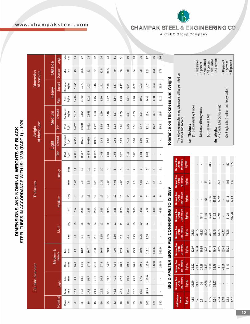
1239 (
PA
RT
1)
- 1979
Bor
eM
axM
inM
axM
inE
ndS
ocke
ted
End
Soc
kete
dE
ndS
ocke
ted
Min
Min
mm
mm
mm
mm
mm
mm
swg
mm
swg
mm
swg
kg/m
kg/m
kg/m
kg/m
kg/m
kg/m
mm
mm
610
.19.
710
.69.
81.
815
2.0
142.
6512
0.36
10.
364
0.40
70.
410
0.49
60.
496
1519
813
.613
.214
.013
.21.
815
2.35
132.
911
0.51
70.
521
0.65
00.
654
0.76
90.
773
18.5
27
1017
.116
.717
.516
.71.
815
2.35
132.
911
0.67
40.
680
0.85
20.
858
1.02
1.03
2228
1521
.421
.021
.821
.02.
014
2.65
123.
2510
0.95
20.
951
1.22
1.23
1.45
1.46
2737
2026
.926
.427
.326
.52.
3513
2.65
123.
2510
1.41
1.42
1.58
1.59
1.90
1.91
32.5
39
2533
.833
.234
.233
.32.
6512
3.25
104.
058
2.01
2.03
2.44
2.46
2.97
2.99
39.5
46
3242
.541
.942
.942
.02.
6512
3.25
104.
058
2.58
2.61
3.14
3.17
3.84
3.87
4951
4048
.447
.848
.847
.92.
911
3.25
104.
058
3.25
3.29
3.61
3.65
4.43
4.47
5651
5060
.259
.660
.859
.72.
911
3.65
94.
57
4.11
4.18
5.10
5.17
6.17
6.24
6860
6576
.075
.276
.675
.33.
2510
3.65
94.
57
5.80
5.92
6.51
6.63
7.90
8.02
8469
8088
.787
.989
.588
.03.
2510
4.05
84.
856
6.81
6.98
8.47
8.64
10.1
10.3
9875
100
113.
911
3.0
115.
011
3.1
3.65
94.
57
5.4
59.
8910
.212
.112
.414
.414
.712
487
125
--
140.
813
8.5
--
4.85
65.
45
--
16.2
16.7
17.8
18.3
151
96
150
--
166.
516
3.9
--
4.85
65.
45
--
19.2
19.8
21.2
21.8
178
96
Plai
nSc
rewe
dPl
ain
Scre
wed
Plai
nSc
rew
edD
iam
eter
Leng
th
Ligh
t M
ediu
mH
eavy
Out
side
Outs
ide
dia
mete
rT
hic
kn
ess
Tole
ran
ce
on
Th
ickn
ess a
nd
We
igh
t
Wal
l Thi
ckne
ssin
mm
Nom
inal
Bor
e7"
NB
19
3.7
mm
OD
Nom
inal
Bor
e8"
NB
21
9.1
mm
OD
Nom
inal
Bor
e10
" N
B
273
mm
OD
Nom
inal
Bor
e12
" N
B
323.
7 m
m O
D
Nom
inal
Bor
e14
" N
B
355.
6 m
m O
D
Nom
inal
Bor
e16
" N
B
406.
4 m
m O
D
Nom
inal
Bor
e18
" N
B
457
mm
OD
Nom
inal
Bor
e20
" N
B
508
mm
OD
kg/m
trkg
/mtr
kg/m
trkg
/mtr
kg/m
trkg
/mtr
kg/m
trkg
/mtr
kg/m
tr
4.85
22.5
925
.62
32.0
738
.13
--
--
5.2
24.1
727
.43
34.3
440
.85
--
--
5.6
2629
.28
36.9
343
.93
48.1
1-
--
627
.88
31.5
339
.547
.02
51.4
961
69-
6.35
29.3
433
.28
41.7
349
.67
54.4
362
.35
70.5
78.5
7.01
32.2
736
.76
46.4
355
.45
61.8
269
.04
--
7.94
-41
50.9
561
.85
67.9
877
.92
87.8
-
8.18
-42
.56
53.4
265
.12
--
--
9.53
-51
.560
.24
73.7
581
.21
93.1
310
511
7
12.7
--
--
107.
2812
3.3
139
155
12
Mediu
mH
eavy
Lig
ht
Nom
inal
Lig
ht
Med
ium
&
Hea
vy
Dim
en
sio
no
f so
cke
tsW
eig
ht
of b
lack
tu
be
w w w . c h a m p a k s t e e l . c o m
A C S E C G r o u p C o m p a n y
CHAMPAK STEEL & ENGINEERING CO .CHAMPAK STEEL & ENGINEERING CO .CHAMPAK STEEL & ENGINEERING CO .CHAMPAK STEEL & ENGINEERING CO .
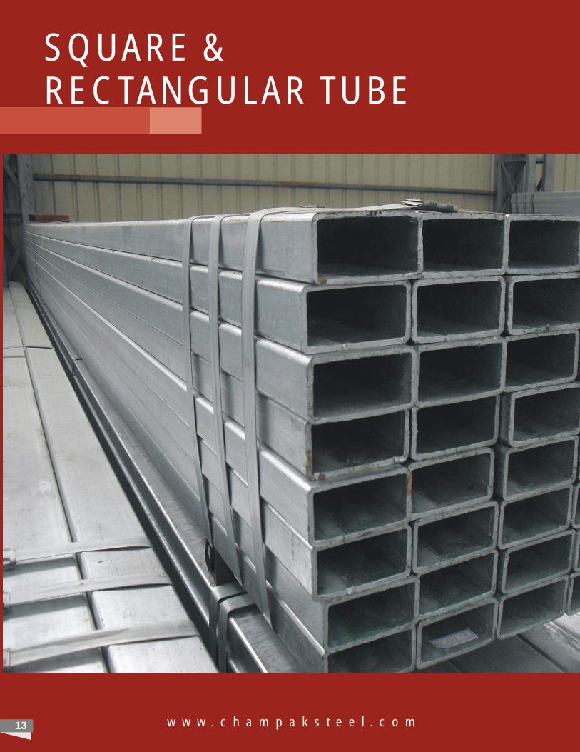
SQUARE &RECTANGULAR TUBE
w w w . c h a m p a k s t e e l . c o m13
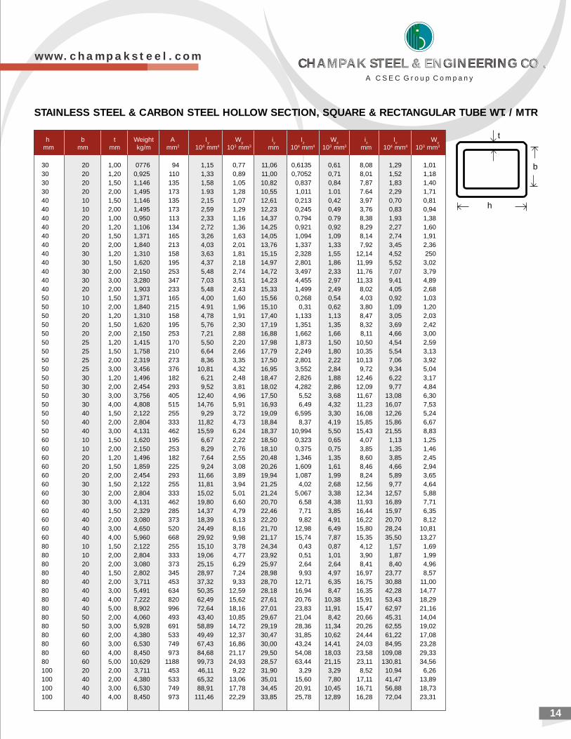
h b t Weight A I W i I W i I Wy y y z z z v v
mm mm mm kg/m mm2 104 mm4 103 mm3 mm 104 mm4 103 mm3 mm 104 mm4 103 mm3
30 20 1,00 0776 94 1,15 0,77 11,06 0,6135 0,61 8,08 1,29 1,0130 20 1,20 0,925 110 1,33 0,89 11,00 0,7052 0,71 8,01 1,52 1,1830 20 1,50 1,146 135 1,58 1,05 10,82 0,837 0,84 7,87 1,83 1,4030 20 2,00 1,495 173 1.93 1,28 10,55 1,011 1.01 7.64 2,29 1,7140 10 1,50 1,146 135 2,15 1,07 12,61 0,213 0,42 3,97 0,70 0,8140 10 2,00 1,495 173 2,59 1,29 12,23 0,245 0,49 3,76 0,83 0,9440 20 1,00 0,950 113 2,33 1,16 14,37 0,794 0.79 8,38 1,93 1,3840 20 1,20 1,106 134 2,72 1,36 14,25 0,921 0,92 8,29 2,27 1,6040 20 1,50 1,371 165 3,26 1,63 14,05 1,094 1,09 8,14 2,74 1,9140 20 2,00 1,840 213 4,03 2,01 13,76 1,337 1,33 7,92 3,45 2,3640 30 1,20 1,310 158 3,63 1,81 15,15 2,328 1,55 12,14 4,52 25040 30 1,50 1,620 195 4,37 2,18 14,97 2,801 1,86 11,99 5,52 3,0240 30 2,00 2,150 253 5,48 2,74 14,72 3,497 2,33 11,76 7,07 3,7940 30 3,00 3,280 347 7,03 3,51 14,23 4,455 2,97 11,33 9,41 4,8940 20 2,00 1,903 233 5,48 2,43 15,33 1,499 2,49 8,02 4,05 2,6850 10 1,50 1,371 165 4,00 1,60 15,56 0,268 0,54 4,03 0,92 1,0350 10 2,00 1,840 215 4.91 1,96 15,10 0,31 0,62 3,80 1,09 1,2050 20 1,20 1,310 158 4,78 1,91 17,40 1,133 1,13 8,47 3,05 2,0350 20 1,50 1,620 195 5,76 2,30 17,19 1,351 1,35 8,32 3,69 2,4250 20 2,00 2,150 253 7,21 2,88 16,88 1,662 1,66 8,11 4,66 3,0050 25 1,20 1,415 170 5,50 2,20 17,98 1,873 1,50 10,50 4,54 2,5950 25 1,50 1,758 210 6,64 2,66 17,79 2,249 1,80 10,35 5,54 3,1350 25 2,00 2,319 273 8,36 3,35 17,50 2,801 2,22 10,13 7,06 3,9250 25 3,00 3,456 376 10,81 4,32 16,95 3,552 2,84 9,72 9,34 5,0450 30 1,20 1,496 182 6,21 2,48 18,47 2,826 1,88 12,46 6,22 3,1750 30 2,00 2,454 293 9,52 3,81 18,02 4,282 2,86 12,09 9,77 4,8450 30 3,00 3,756 405 12,40 4,96 17,50 5,52 3,68 11,67 13,08 6,3050 30 4,00 4,808 515 14,76 5,91 16,93 6,49 4,32 11,23 16,07 7,5350 40 1,50 2,122 255 9,29 3,72 19,09 6,595 3,30 16,08 12,26 5,2450 40 2,00 2,804 333 11,82 4,73 18,84 8,37 4,19 15,85 15,86 6,6750 40 3,00 4,131 462 15,59 6,24 18,37 10,994 5,50 15,43 21,55 8,8360 10 1,50 1,620 195 6,67 2,22 18,50 0,323 0,65 4,07 1,13 1,2560 10 2,00 2,150 253 8,29 2,76 18,10 0,375 0,75 3,85 1,35 1,4660 20 1,20 1,496 182 7,64 2,55 20,48 1,346 1,35 8,60 3,85 2,4560 20 1,50 1,859 225 9,24 3,08 20,26 1,609 1,61 8,46 4,66 2,9460 20 2,00 2,454 293 11,66 3,89 19,94 1,087 1,99 8,24 5,89 3,6560 30 1,50 2,122 255 11,81 3,94 21,25 4,02 2,68 12,56 9,77 4,6460 30 2,00 2,804 333 15,02 5,01 21,24 5,067 3,38 12,34 12,57 5,8860 30 3,00 4,131 462 19,80 6,60 20,70 6,58 4,38 11,93 16,89 7,7160 40 1,50 2,329 285 14,37 4,79 22,46 7,71 3,85 16,44 15,97 6,3560 40 2,00 3,080 373 18,39 6,13 22,20 9,82 4,91 16,22 20,70 8,1260 40 3,00 4,650 520 24,49 8,16 21,70 12,98 6,49 15,80 28,24 10,8160 40 4,00 5,960 668 29,92 9,98 21,17 15,74 7,87 15,35 35,50 13,2780 10 1,50 2,122 255 15,10 3,78 24,34 0,43 0,87 4,12 1,57 1,6980 10 2,00 2,804 333 19,06 4,77 23,92 0,51 1,01 3,90 1,87 1,9980 20 2,00 3,080 373 25,15 6,29 25,97 2,64 2,64 8,41 8,40 4,9680 40 1,50 2,802 345 28,97 7,24 28,98 9,93 4,97 16,97 23,77 8,5780 40 2,00 3,711 453 37,32 9,33 28,70 12,71 6,35 16,75 30,88 11,0080 40 3,00 5,491 634 50,35 12,59 28,18 16,94 8,47 16,35 42,28 14,7780 40 4,00 7,222 820 62,49 15,62 27,61 20,76 10,38 15,91 53,43 18,2980 40 5,00 8,902 996 72,64 18,16 27,01 23,83 11,91 15,47 62,97 21,1680 50 2,00 4,060 493 43,40 10,85 29,67 21,04 8,42 20,66 45,31 14,0480 50 3,00 5,928 691 58,89 14,72 29,19 28,36 11,34 20,26 62,55 19,0280 60 2,00 4,380 533 49,49 12,37 30,47 31,85 10,62 24,44 61,22 17,0880 60 3,00 6,530 749 67,43 16,86 30,00 43,24 14,41 24,03 84,95 23,2880 60 4,00 8,450 973 84,68 21,17 29,50 54,08 18,03 23,58 109,08 29,3380 60 5,00 10,629 1188 99,73 24,93 28,57 63,44 21,15 23,11 130,81 34,56100 20 2,00 3,711 453 46,11 9,22 31,90 3,29 3,29 8,52 10,94 6,26100 40 2,00 4,380 533 65,32 13,06 35,01 15,60 7,80 17,11 41,47 13,89100 40 3,00 6,530 749 88,91 17,78 34,45 20,91 10,45 16,71 56,88 18,73100 40 4,00 8,450 973 111,46 22,29 33,85 25,78 12,89 16,28 72,04 23,31
t
b
h
STAINLESS STEEL & CARBON STEEL HOLLOW SECTION, SQUARE & RECTANGULAR TUBE WT. / MTR
14
w w w . c h a m p a k s t e e l . c o m
A C S E C G r o u p C o m p a n y
CHAMPAK STEEL & ENGINEERING CO .CHAMPAK STEEL & ENGINEERING CO .CHAMPAK STEEL & ENGINEERING CO .CHAMPAK STEEL & ENGINEERING CO .
2115
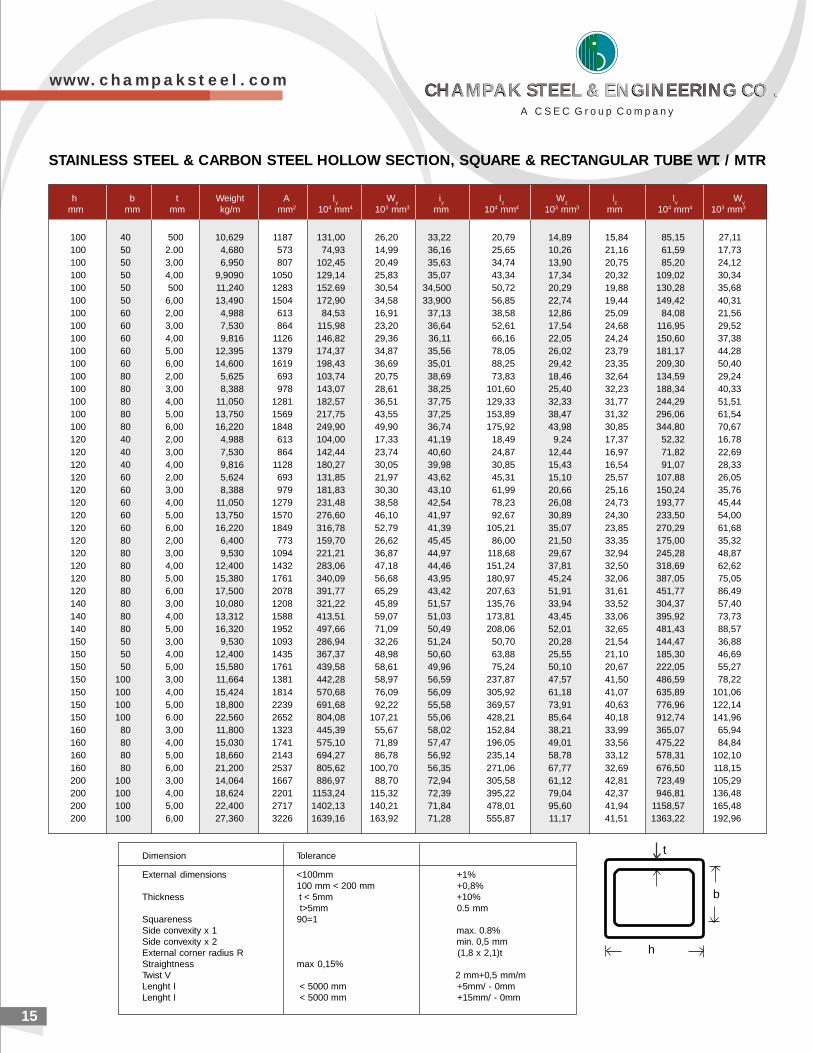
h b t Weight A I W i I W i I Wy y y z z z v v
mm mm mm kg/m mm2 104 mm4 103 mm3 mm 104 mm4 103 mm3 mm 104 mm4 103 mm3
100 40 500 10,629 1187 131,00 26,20 33,22 20,79 14,89 15,84 85,15 27,11100 50 2.00 4,680 573 74,93 14,99 36,16 25,65 10,26 21,16 61,59 17,73100 50 3,00 6,950 807 102,45 20,49 35,63 34,74 13,90 20,75 85,20 24,12100 50 4,00 9,9090 1050 129,14 25,83 35,07 43,34 17,34 20,32 109,02 30,34100 50 500 11,240 1283 152.69 30,54 34,500 50,72 20,29 19,88 130,28 35,68100 50 6,00 13,490 1504 172,90 34,58 33,900 56,85 22,74 19,44 149,42 40,31100 60 2,00 4,988 613 84,53 16,91 37,13 38,58 12,86 25,09 84,08 21,56100 60 3,00 7,530 864 115,98 23,20 36,64 52,61 17,54 24,68 116,95 29,52100 60 4,00 9,816 1126 146,82 29,36 36,11 66,16 22,05 24,24 150,60 37,38100 60 5,00 12,395 1379 174,37 34,87 35,56 78,05 26,02 23,79 181,17 44,28100 60 6,00 14,600 1619 198,43 36,69 35,01 88,25 29,42 23,35 209,30 50,40100 80 2,00 5,625 693 103,74 20,75 38,69 73,83 18,46 32,64 134,59 29,24100 80 3,00 8,388 978 143,07 28,61 38,25 101,60 25,40 32,23 188,34 40,33100 80 4,00 11,050 1281 182,57 36,51 37,75 129,33 32,33 31,77 244,29 51,51100 80 5,00 13,750 1569 217,75 43,55 37,25 153,89 38,47 31,32 296,06 61,54100 80 6,00 16,220 1848 249,90 49,90 36,74 175,92 43,98 30,85 344,80 70,67120 40 2,00 4,988 613 104,00 17,33 41,19 18,49 9,24 17,37 52,32 16,78120 40 3,00 7,530 864 142,44 23,74 40,60 24,87 12,44 16,97 71,82 22,69120 40 4,00 9,816 1128 180,27 30,05 39,98 30,85 15,43 16,54 91,07 28,33120 60 2,00 5,624 693 131,85 21,97 43,62 45,31 15,10 25,57 107,88 26,05120 60 3,00 8,388 979 181,83 30,30 43,10 61,99 20,66 25,16 150,24 35,76120 60 4,00 11,050 1279 231,48 38,58 42,54 78,23 26,08 24,73 193,77 45,44120 60 5,00 13,750 1570 276,60 46,10 41,97 92,67 30,89 24,30 233,50 54,00120 60 6,00 16,220 1849 316,78 52,79 41,39 105,21 35,07 23,85 270,29 61,68120 80 2,00 6,400 773 159,70 26,62 45,45 86,00 21,50 33,35 175,00 35,32120 80 3,00 9,530 1094 221,21 36,87 44,97 118,68 29,67 32,94 245,28 48,87120 80 4,00 12,400 1432 283,06 47,18 44,46 151,24 37,81 32,50 318,69 62,62120 80 5,00 15,380 1761 340,09 56,68 43,95 180,97 45,24 32,06 387,05 75,05120 80 6,00 17,500 2078 391,77 65,29 43,42 207,63 51,91 31,61 451,77 86,49140 80 3,00 10,080 1208 321,22 45,89 51,57 135,76 33,94 33,52 304,37 57,40140 80 4,00 13,312 1588 413,51 59,07 51,03 173,81 43,45 33,06 395,92 73,73140 80 5,00 16,320 1952 497,66 71,09 50,49 208,06 52,01 32,65 481,43 88,57150 50 3,00 9,530 1093 286,94 32,26 51,24 50,70 20,28 21,54 144,47 36,88150 50 4,00 12,400 1435 367,37 48,98 50,60 63,88 25,55 21,10 185,30 46,69150 50 5,00 15,580 1761 439,58 58,61 49,96 75,24 50,10 20,67 222,05 55,27150 100 3,00 11,664 1381 442,28 58,97 56,59 237,87 47,57 41,50 486,59 78,22150 100 4,00 15,424 1814 570,68 76,09 56,09 305,92 61,18 41,07 635,89 101,06150 100 5,00 18,800 2239 691,68 92,22 55,58 369,57 73,91 40,63 776,96 122,14150 100 6.00 22,560 2652 804,08 107,21 55,06 428,21 85,64 40,18 912,74 141,96160 80 3,00 11,800 1323 445,39 55,67 58,02 152,84 38,21 33,99 365,07 65,94160 80 4,00 15,030 1741 575,10 71,89 57,47 196,05 49,01 33,56 475,22 84,84160 80 5,00 18,660 2143 694,27 86,78 56,92 235,14 58,78 33,12 578,31 102,10160 80 6,00 21,200 2537 805,62 100,70 56,35 271,06 67,77 32,69 676,50 118,15200 100 3,00 14,064 1667 886,97 88,70 72,94 305,58 61,12 42,81 723,49 105,29200 100 4,00 18,624 2201 1153,24 115,32 72,39 395,22 79,04 42,37 946,81 136,48200 100 5,00 22,400 2717 1402,13 140,21 71,84 478,01 95,60 41,94 1158,57 165,48200 100 6,00 27,360 3226 1639,16 163,92 71,28 555,87 11,17 41,51 1363,22 192,96
t
b
h
Dimension Tolerance
External dimensions <100mm +1%100 mm < 200 mm +0,8%
Thickness t < 5mm +10% t>5mm 0.5 mm
Squareness 90=1Side convexity x 1 max. 0.8%Side convexity x 2 min. 0,5 mmExternal corner radius R (1,8 x 2,1)tStraightness max 0,15%Twist V 2 mm+0,5 mm/mLenght I < 5000 mm +5mm/ - 0mmLenght I < 5000 mm +15mm/ - 0mm
STAINLESS STEEL & CARBON STEEL HOLLOW SECTION, SQUARE & RECTANGULAR TUBE WT. / MTR
w w w . c h a m p a k s t e e l . c o m
A C S E C G r o u p C o m p a n y
CHAMPAK STEEL & ENGINEERING CO .CHAMPAK STEEL & ENGINEERING CO .CHAMPAK STEEL & ENGINEERING CO .CHAMPAK STEEL & ENGINEERING CO .
2016
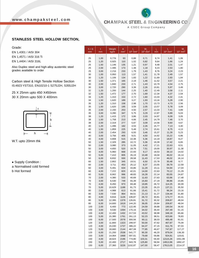
Grade: EN 1,4301 / AISI 304
EN 1,4571 / AISI 316 Ti
EN 1,4404 / AISI 316L
Also Duplex steel and high-alloy austenitic steelgrades available to order
Carbon steel & High Tensile Hollow SectionIS:4923 YST310, EN10210-1 S275J2H, S355J2H
25 X 25mm upto 450 X450mm30 X 20mm upto 500 X 400mm
t
b
h
STAINLESS STEEL HOLLOW SECTION,
W.T. upto 20mm thk
l Supply Condition :a Normalised cold formedb Hot formed
h = b t Weight A I W i I Wy y y z z
mm mm kg/m mm2 104 mm4 103 mm3 mm 104 mm4 103 mm3
25 1,00 0,776 93 0,88 0,71 9,74 1,41 1,0625 1,20 0,925 110 1,02 0,82 9,64 1,66 1,2425 1,50 1,146 135 1,21 0,97 9,48 2,01 1,4725 2,00 1.495 173 1,48 1,18 9,23 2,53 1,8025 3,00 2,216 233 1,79 1,43 8,76 3,24 2,2330 1,00 0,950 113 1,57 1,41 11,78 2,49 1,5730 1,20 1,106 134 1,83 1,22 11,69 2,93 1,8430 1,50 1,371 165 2,19 1,46 11,52 3,57 2,2130 2,00 1,840 233 2,71 1,43 10,79 4,54 2,7530 3,00 2,720 290 3,39 2,26 10,81 5,97 3,4932 1,20 1,200 144 2,25 1,40 12,49 3,58 2,1132 1,50 1,472 177 2,70 1,69 12,34 4,37 2,5434 1,20 1,310 153 2,72 1,60 13,33 4,32 2,4134 1,50 1,620 189 3,27 1,93 13,16 5,28 2,9035 1,20 1,310 158 2,98 1,70 13,73 4,73 2,5635 1,50 1,620 195 3,59 2,05 13,57 5,78 3,0935 2,00 2,150 253 4,50 2,57 13,33 7,41 3,8935 3,00 3,280 347 5,75 3,29 12,87 9,89 5,0338 1,20 1,415 172 3,86 2,03 14,97 6,09 3,0538 1,50 1,758 213 4,66 2,45 14,79 7,46 3,7038 2,00 2,319 277 5,87 3,09 14,56 9,60 4,6740 1,20 1,496 182 4,53 2,26 15,77 7,13 3,4040 1,50 1,859 225 5,48 2,74 15,61 8,75 4,1340 2,00 2,454 293 6,93 3,46 15,37 11,28 5,2340 3,00 3,756 405 9,01 4,50 14,92 15,22 6,8640 4,00 4,808 515 10,38 5,36 14,19 18,87 8,2750 1,50 2,329 285 10,72 5,36 19,39 17,42 6,6550 2,00 3,080 373 11,05 4,42 17,21 22,63 8,5150 3,00 4,650 520 18,78 7,51 19,00 30,97 11,3850 4,00 5,960 668 22,93 9,17 18,53 39,10 14,0250 5,00 7,410 805 26,19 10,48 18,04 46,02 16,1450 6,00 8,832 930 28,58 11,43 17,53 46,02 16,1460 1,50 2,802 345 19,51 6,50 23,78 30,48 9,7760 2,00 3,711 453 25,12 8,37 23,55 39,79 12,5960 3,00 5,491 634 33,86 11,29 23,11 54,94 17,0460 4,00 7,222 820 42,01 14,00 22,63 70,12 21,2960 5,00 8,902 996 48.83 16,28 22,14 83,55 24,8770 2,00 4,380 533 40,69 11,63 27,63 63,96 17,4870 3,00 6,530 749 55,39 15,83 27,19 88,86 23,8570 4,00 8,450 973 69,48 19,85 26,72 114.25 30,0970 5,00 10,629 1188 81,73 23,35 26,23 137,21 35,5080 2,00 4,988 613 61,66 15,41 31,72 96,34 23,1680 3,00 7,530 864 84,51 21,13 31,27 134,44 31,8080 4,00 9,816 1126 106,87 26,72 30,81 173,77 40,4180 5,00 12,395 1379 126,81 31,72 30,32 209,87 48,0480 6,00 14,600 1619 144,20 36,05 29,84 209,87 48,04100 2,00 6,400 773 122,95 24,59 39,88 190,54 36,92100 3,00 9,530 1094 170,16 34,02 39,44 267,49 51,15100 4,00 12,400 1432 217,53 43,52 38,98 348,18 65,66100 5,00 15,380 1761 261,13 52,23 38,51 423,66 78,83100 6,00 17,500 2078 300,56 60,11 38,03 495,48 91,01120 3,00 11,800 1323 299,97 50,00 47,62 467,87 75,09120 4,00 15,030 1737 386,22 64,37 47,15 611,76 97,03120 5,00 18,660 2144 467,08 77,85 46,67 747,87 117,27120 6,00 21,200 2538 541,77 90,30 46,20 879,04 136,30150 3,00 14,064 1668 597,61 79,68 59,86 924,81 119,61150 4,00 18,624 2196 774,80 103,31 59,40 12115,26 1551,99150 5,00 22,400 2717 943,78 125,80 58,94 14913,96 1892,47150 6,00 27,360 3226 1102,87 147,00 58,47 17613,05 2214,37
w w w . c h a m p a k s t e e l . c o m
A C S E C G r o u p C o m p a n y
CHAMPAK STEEL & ENGINEERING CO .CHAMPAK STEEL & ENGINEERING CO .CHAMPAK STEEL & ENGINEERING CO .CHAMPAK STEEL & ENGINEERING CO .
PLATES
w w w . c h a m p a k s t e e l . c o m
Stainless Steel Plates
Stainless Steel Duplex & Super Duplex Plates
Pressure Vessel & Boiler Quality Steel Plates
NACE HIC Steel
Hot Rolled Low, Medium and High Tensile Structural Steel
Abrasion Resistant Steel Plates
Quenched & Tempered Steel Plates
Alloy Steel Chrome Moly Plates
Corten Steel Plates
Hadfield Manganese Steel Plate
17
Type
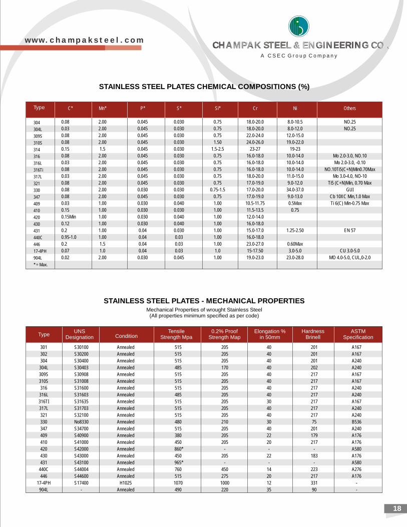
STAINLESS STEEL PLATES CHEMICAL COMPOSITIONS (%)
C Mn P S Si* * * * * Cr Ni Others
0.08 2.00 0.045 0.030 0.75 18.0-20.0 8.0-10.5 NO.25
0.03 2.00 0.045 0.030 0.75 18.0-20.0 8.0-12.0 NO.25
0.08 2.00 0.045 0.030 0.75 22.0-24.0 12.0-15.0
0.08 2.00 0.045 0.030 1.50 24.0-26.0 19.0-22.0
0.15 1.5 0.045 0.030 1.5-2.5 23-27 19-23
0.08 2.00 0.045 0.030 0.75 16.0-18.0 10.0-14.0 Mo 2.0-3.0, NO.10
0.03 2.00 0.045 0.030 0.75 16.0-18.0 10.0-14.0 Mo 2.0-3.0, -0.10
0.08 2.00 0.045 0.030 0.75 16.0-18.0 10.0-14.0 NO.10Ti5(C+N)Min0.70Max
0.03 2.00 0.045 0.030 0.75 18.0-20.0 11.0-15.0 Mo 3.0-4.0, NO-10
0.08 2.00 0.045 0.030 0.75 17.0-19.0 9.0-12.0 Ti5 (C+N)Min, 0.70 Max
0.08 2.00 0.030 0.030 0.75-1.5 17.0-20.0 34.0-37.0 GUI
0.08 2.00 0.045 0.030 0.75 17.0-19.0 9.0-13.0 Cb 10XC Min,1.0 Max
0.03 1.00 0.030 0.040 1.00 10.5-11.75 0.5Max Ti 6(C) Min-0.75 Max
0.15 1.00 0.030 0.030 1.00 11.5-13.5 0.75
0.15Min 1.00 0.030 0.040 1.00 12.0-14.0
0.12 1.00 0.030 0.040 1.00 16.0-18.0
0.2 1.00 0.04 0.030 1.00 15.0-17.0 1.25-2.50 EN 57
0.95-1.0 1.00 0.04 0.03 1.00 16.0-18.0
0.2 1.5 0.04 0.03 1.00 23.0-27.0 0.60Max
0.07 1.0 0.04 0.03 1.0 15-17.50 3.0-5.0 CU 3.0-5.0
0.02 2.00 0.030 0.045 1.00 19.0-23.0 23.0-28.0 MO 4.0-5.0, CUL,0-2.0
304
304L
309S
310S
314
316
316L
316Ti
317L
321
330
347
409
410
420
430
431
440C
446
17-4PH
904L
* = Max.
STAINLESS STEEL - MECHANICAL PROPERTIESPLATESMechanical Properties of wrought Stainless Steel
(All properties minimum specified as per code)
TypeUNS
Designation ConditionTensile
Strength Mpa0.2% Proof
Strength MapElongation %
in 50mmHardness
BrinellASTM
Specification
18
301 S30100 Annealed 515 205 40 201 A167
302 S30200 Annealed 515 205 40 201 A167
304 S30400 Annealed 515 205 40 201 A240
304L S30403 Annealed 485 170 40 202 A240
309S S30908 Annealed 515 205 40 217 A167
310S S31008 Annealed 515 205 40 217 A167
316 S31600 Annealed 515 205 40 217 A240
316L S31603 Annealed 485 205 40 217 A240
316TI S31635 Annealed 515 205 30 217 A167
317L S31703 Annealed 515 205 40 217 A240
321 S32100 Annealed 515 205 40 217 A240
330 No8330 Annealed 480 210 30 75 B536
347 S34700 Annealed 515 205 40 201 A240
409 S40900 Annealed 380 205 22 179 A176
410 S41000 Annealed 450 205 20 217 A176
420 S42000 Annealed 860* - - - A580
430 S43000 Annealed 450 205 22 183 A176
431 S43100 Annealed 965* - - - A580
440C S44004 Annealed 760 450 14 223 A276
446 S44600 Annealed 515 275 20 217 A176
17-4PH S17400 H1025 1070 1000 12 331 -
904L - Annealed 490 220 35 90 -
w w w . c h a m p a k s t e e l . c o m
A C S E C G r o u p C o m p a n y
CHAMPAK STEEL & ENGINEERING CO .CHAMPAK STEEL & ENGINEERING CO .CHAMPAK STEEL & ENGINEERING CO .CHAMPAK STEEL & ENGINEERING CO .
19
JS3
12
00
...
10
06
90
65
45
02
5.0
29
33
1no
t re
quire
d
S31
26
0..
.1
00
69
07
04
85
20
.02
90
...
...
JS3
18
03
...
90
62
06
54
50
25
.02
93
31
no
t re
quire
d
GS3
20
01
...
90
62
06
54
50
25
.0..
.2
5no
t re
quire
d
FJ
S32
20
52
20
59
06
20
65
45
02
5.0
29
33
1no
t re
quire
d
FJ
S32
30
42
30
48
76
00
58
40
02
5.0
29
03
2no
t re
quire
d
S32
52
0..
.1
12
76
08
05
50
25
.03
10
...
no
t re
quire
d
FJ
S32
55
02
55
11
07
60
80
55
01
5.0
30
23
2no
t re
quire
d
FJ
S32
75
02
50
71
16
79
58
05
50
15
.03
10
32
no
t re
quire
d
S32
76
0..
.1
08
75
08
05
50
25
.02
70
...
no
t re
quire
d
S32
90
03
29
90
62
07
04
85
15
.02
69
28
no
t re
quire
d
MS3
29
50
...
10
06
90
70
48
51
5.0
29
33
2no
t re
quire
d
UN
S D
esi
gnatio
n B
Type
A
Tensi
le S
trength
, m
in Y
ield
Str
ength
,B m
inE
longatio
n i
n H
ard
ness
, m
ax
cC
old
Bend
0D
2 in.
or
50
mm
,
Ksi
MP
aK
si
MP
am
in,%
Brin
ell
Rock
well
B
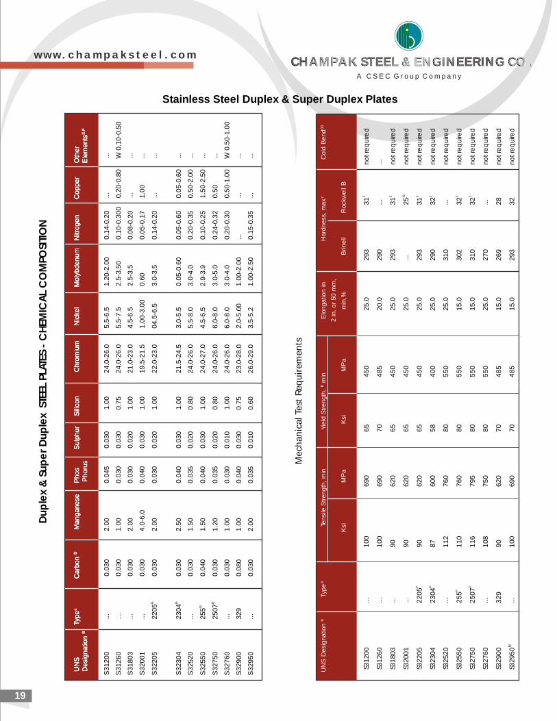
Mec
hani
cal T
est R
equi
rem
ents
S3
12
00
...
0.0
30
2.0
00
.04
50
.03
01
.00
24
.0-2
6.0
5.5
-6.5
1.2
0-2
.00
0.1
4-0
.20
...
...
S3
12
60
…0
.03
01
.00
0.0
30
0.0
30
0.7
52
4.0
-26
.05
.5-7
.52
.5-3
.50
0.1
0-0
.30
00
.20
-0.8
0W
0.1
0-0
.50
S3
18
03
...
0.0
30
2.0
00
.03
00
.02
01
.00
21
.0-2
3.0
4.5
-6.5
2.5
-3.5
0.0
8-0
.20
...
...
S3
20
01
...
0.0
30
4.0
-6.0
0.0
40
0.0
30
1.0
01
9.5
-21
.51
.00
-3.0
00
.60
0.0
5-0
.17
1.0
0...
GS
32
20
52
20
50
.03
02
.00
0.0
30
0.0
20
1.0
02
2.0
-23
.00
4.5
-6.5
3.0
-3.5
0.1
4-0
.20
...
...
GS
32
30
42
30
40
.03
02
.50
0.0
40
0.0
30
1.0
02
1.5
-24
.53
.0-5
.50
.05
-0.6
00
.05
-0.6
00
.05
-0.6
0...
S3
25
20
...
0.0
30
1.5
00
.03
50
.02
00
.80
24
.0-2
6.0
5.5
-8.0
3.0
-4.0
0.2
0-0
.35
0.5
0-2
.00
...
GS
32
55
02
55
0.0
40
1.5
00
.04
00
.03
01
.00
24
.0-2
7.0
4.5
-6.5
2.9
-3.9
0.1
0-0
.25
1.5
0-2
.50
...
GS
32
75
02
50
70
.03
01
.20
0.0
35
0.0
20
0.8
02
4.0
-26
.06
.0-8
.03
.0-5
.00
.24
-0.3
20
.50
...
S3
27
60
...
0.0
30
1.0
00
.03
00
.01
01
.00
24
.0-2
6.0
6.0
-8.0
3.0
-4.0
0.2
0-0
.30
0.5
0-1
.00
W 0
.50
-1.0
0
S3
29
00
32
90
.08
01
.00
0.0
40
0.0
30
0.7
52
3.0
-28
.02
.0-5
.00
1.0
0-2
.00
...
...
...
S3
29
50
...
0.0
30
2.0
00
.03
50
.01
00
.60
26
.0-2
9.0
3.5
-5.2
1.0
0-2
.50
0.1
5-0
.35
...
...
UN
STyp
ec
Carb
on
DM
anganese
Phos
Sulp
hur
Sili
con
Chro
miu
mN
icke
lM
oly
bdenum
Nitr
ogen
Copper
Oth
er
Desi
gnatio
n B
Phoru
sE
lem
ents
E.F
UN
STyp
ec
Carb
on
DM
anganese
Phos
Sulp
hur
Sili
con
Chro
miu
mN
icke
lM
oly
bdenum
Nitr
ogen
Copper
Oth
er
Desi
gnatio
n B
Phoru
sE
lem
ents
E.F
UN
STyp
ec
Carb
on
DM
anganese
S
ulp
hur
Sili
con
Chro
miu
mN
icke
lM
oly
bdenum
Nitr
ogen
Copper
Oth
er
Desi
gnatio
n B
E
lem
ents
E.F
D
up
lex
& S
up
er
Dup
lex
STE
EL P
LATE
S -
CH
EMIC
AL
CO
MPO
SITI
ON
Stainless Steel Duplex & Super Duplex Plates
w w w . c h a m p a k s t e e l . c o m
A C S E C G r o u p C o m p a n y
CHAMPAK STEEL & ENGINEERING CO .CHAMPAK STEEL & ENGINEERING CO .CHAMPAK STEEL & ENGINEERING CO .CHAMPAK STEEL & ENGINEERING CO .
20
Chemical Composition Tensile test ElongationDesignation
C mn si P S Tensile Strength Yield Strength Test % minmax max max max Kf/mm2 Kf/mm2min piece
0.5IS 2002-1 0.18 1.2 0.15-0.35 0.035 0.040 36.7-49 24 23 5.65/Sc 24
0.5IS 2002-2 0.20 1.2 0.15-0.35 0.035 0.40 41.7-54 27 26 5.65/Sc 22
0.5IS 2002-3 0.22 1.2 0.15-0.35 0.035 0.040 46.8-59 29.5 29 5.65/Sc 21
Min. thickness in mm
t<1-1/2(38) t>-1-1/2
TensileStrength
Ksi (MPa)
70-90(485-620)
65-85(450-585)
80-100(550-690)
75-95(515-655)
Thicknessin mm
t<2-1 (64)2-1/2<t
<4 (100)
T<2-1/2(64)2-1/2<t(4(100)
P S Cu Ni Cr Momax max max max max max
Designation CMax
YieldStrength
Ksi(MPa)
min
50(345)
45(310)
60(415)
55(380)
GL= 8 in GL = 2 in
or or
200 mm 50 mm
18 22
- 22
HeatTreat-ment
Tensile Strength Elongation % min%Chemical Composition
A 537 -1 0.24 0.15-0.50 0.70-1.35 1.0-1.60 0.035 0.040 0.035 0.25 0.25 0.08 Normalised
Quenched &A 537 -2 0.24 0.15-0.50 0.70-1.35 1.0-1.60 0.035 0.040 0.035 0.25 0.25 0.08 Tempered
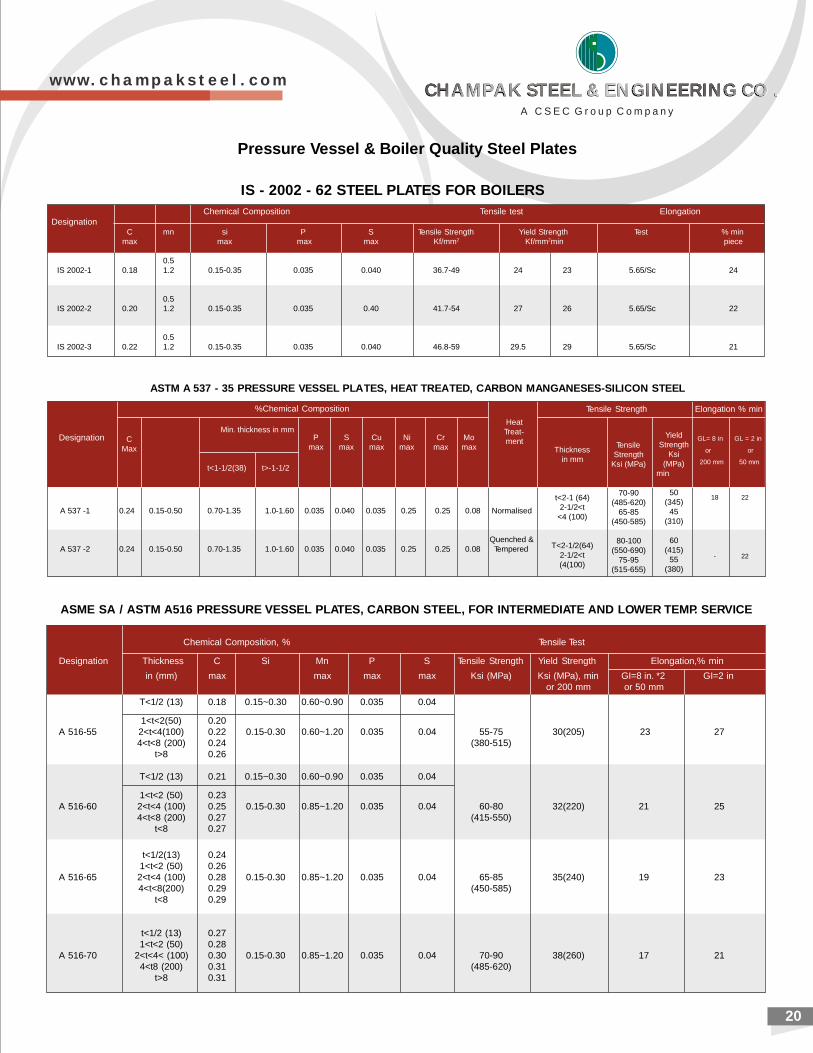
ASTM A 537 - 35 PRESSURE VESSEL PLATES, HEAT TREATED, CARBON MANGANESES-SILICON STEEL
IS - 2002 - 62 STEEL PLATES FOR BOILERS
Chemical Composition, % Tensile Test
Designation Thickness C Si Mn P S Tensile Strength Yield Strength Elongation,% min
in (mm) max max max max Ksi (MPa) Ksi (MPa), min GI=8 in. *2 GI=2 inor 200 mm or 50 mm
T<1/2 (13) 0.18 0.15~0.30 0.60~0.90 0.035 0.04
1<t<2(50) 0.20A 516-55 2<t<4(100) 0.22 0.15-0.30 0.60~1.20 0.035 0.04 55-75 30(205) 23 27
4<t<8 (200) 0.24 (380-515)t>8 0.26
T<1/2 (13) 0.21 0.15~0.30 0.60~0.90 0.035 0.04
1<t<2 (50) 0.23A 516-60 2<t<4 (100) 0.25 0.15-0.30 0.85~1.20 0.035 0.04 60-80 32(220) 21 25
4<t<8 (200) 0.27 (415-550)t<8 0.27
t<1/2(13) 0.241<t<2 (50) 0.26
A 516-65 2<t<4 (100) 0.28 0.15-0.30 0.85~1.20 0.035 0.04 65-85 35(240) 19 234<t<8(200) 0.29 (450-585)
t<8 0.29
t<1/2 (13) 0.271<t<2 (50) 0.28
A 516-70 2<t<4< (100) 0.30 0.15-0.30 0.85~1.20 0.035 0.04 70-90 38(260) 17 214<t8 (200) 0.31 (485-620)
t>8 0.31
ASME SA / ASTM A516 PRESSURE VESSEL PLATES, CARBON STEEL, FOR INTERMEDIATE AND LOWER TEMP. SERVICE
Pressure Vessel & Boiler Quality Steel Plates
w w w . c h a m p a k s t e e l . c o m
A C S E C G r o u p C o m p a n y
CHAMPAK STEEL & ENGINEERING CO .CHAMPAK STEEL & ENGINEERING CO .CHAMPAK STEEL & ENGINEERING CO .CHAMPAK STEEL & ENGINEERING CO .
21
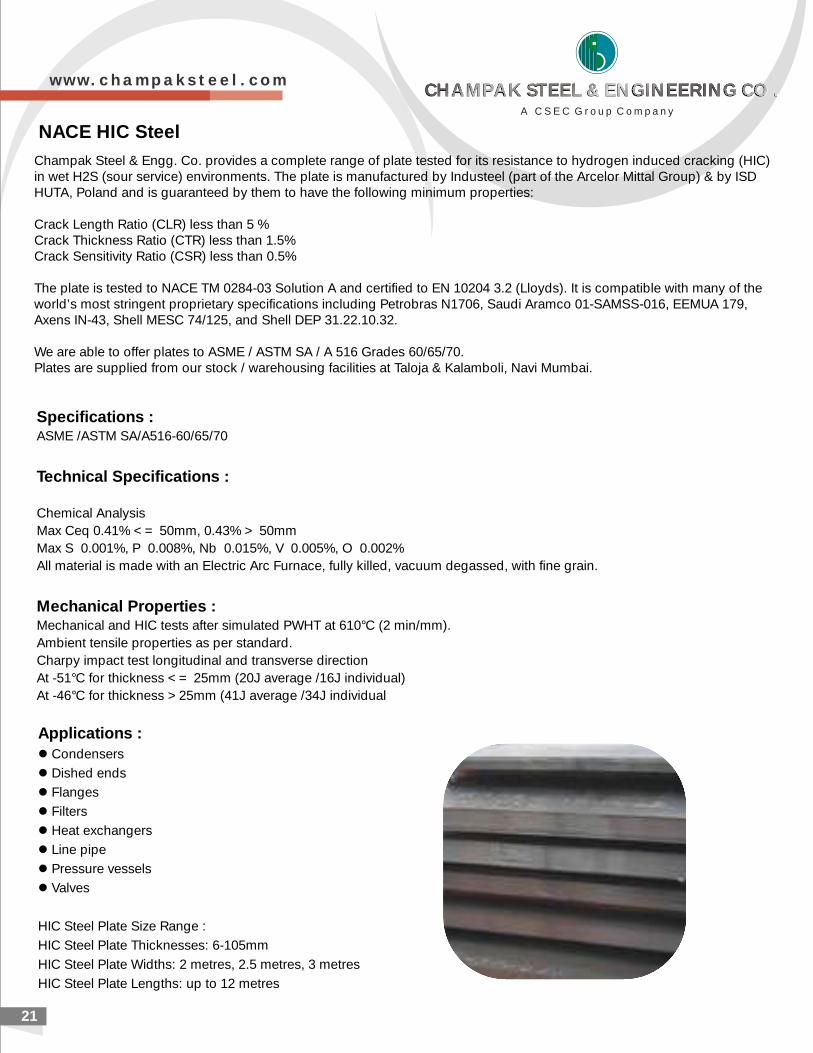
NACE HIC Steel
Champak Steel & Engg. Co. provides a complete range of plate tested for its resistance to hydrogen induced cracking (HIC) in wet H2S (sour service) environments. The plate is manufactured by Industeel (part of the Arcelor Mittal Group) & by ISD HUTA, Poland and is guaranteed by them to have the following minimum properties:
Crack Length Ratio (CLR) less than 5 %Crack Thickness Ratio (CTR) less than 1.5%Crack Sensitivity Ratio (CSR) less than 0.5%
The plate is tested to NACE TM 0284-03 Solution A and certified to EN 10204 3.2 (Lloyds). It is compatible with many of the world’s most stringent proprietary specifications including Petrobras N1706, Saudi Aramco 01-SAMSS-016, EEMUA 179, Axens IN-43, Shell MESC 74/125, and Shell DEP 31.22.10.32.
We are able to offer plates to ASME / ASTM SA / A 516 Grades 60/65/70. Plates are supplied from stock / warehousing facilities at Taloja & Kalamboli, Navi Mumbai.our
Specifications :ASME /ASTM SA/A516-60/65/70
Technical Specifications :
Chemical Analysis
Max Ceq 0.41% <= 50mm, 0.43% > 50mm
Max S 0.001%, P 0.008%, Nb 0.015%, V 0.005%, O 0.002%
All material is made with an Electric Arc Furnace, fully killed, vacuum degassed, with fine grain.
Mechanical Properties : Mechanical and HIC tests after simulated PWHT at 610°C (2 min/mm).
Ambient tensile properties as per standard.
Charpy impact test longitudinal and transverse direction
At -51°C for thickness <= 25mm (20J average /16J individual)
At -46°C for thickness >25mm (41J average /34J individual
Applications : l Condensers
l Dished ends
l Flanges
l Filters
l Heat exchangers
l Line pipe
l Pressure vessels
l Valves
HIC Steel Plate Size Range :
HIC Steel Plate Thicknesses: 6-105mm
HIC Steel Plate Widths: 2 metres, 2.5 metres, 3 metres
HIC Steel Plate Lengths: up to 12 metres
w w w . c h a m p a k s t e e l . c o m
A C S E C G r o u p C o m p a n y
CHAMPAK STEEL & ENGINEERING CO .CHAMPAK STEEL & ENGINEERING CO .CHAMPAK STEEL & ENGINEERING CO .CHAMPAK STEEL & ENGINEERING CO .
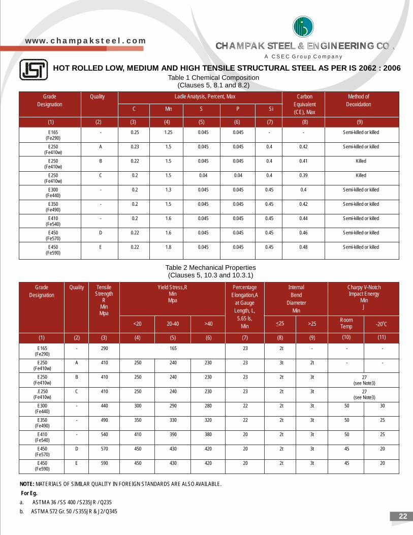
E165 - 0.25 1.25 0.045 0.045 - - Semi-killed or killed(Fe290)
E250 A 0.23 1.5 0.045 0.045 0.4 0.42 Semi-killed or killed(Fe410w)
E250 B 0.22 1.5 0.045 0.045 0.4 0.41 Killed(Fe410w)
E250 C 0.2 1.5 0.04 0.04 0.4 0.39 Killed(Fe410w)
E300 - 0.2 1.3 0.045 0.045 0.45 0.4 Semi-killed or killed(Fe440)
E350 - 0.2 1.5 0.045 0.045 0.45 0.42 Semi-killed or killed(Fe490)
E410 - 0.2 1.6 0.045 0.045 0.45 0.44 Semi-killed or killed(Fe540)
E450 D 0.22 1.6 0.045 0.045 0.45 0.46 Semi-killed or killed(Fe570)
E450 E 0.22 1.8 0.045 0.045 0.45 0.48 Semi-killed or killed(Fe590)
E165 - 290 165 23 2t - - -(Fe290)
E250 A 410 250 240 230 23 3t 2t - -(Fe410w)
E250 B 410 250 240 230 23 2t 3t(Fe410w)
.E250 C 410 250 240 230 23 2t 3t(Fe410w)
E300 - 440 300 290 280 22 2t 3t 50 30(Fe440)
E350 - 490 350 330 320 22 2t 3t 50 25(Fe490)
E410 - 540 410 390 380 20 2t 3t 50 25(Fe540)
E450 D 570 450 430 420 20 2t 3t 45 20(Fe570)
E450 E 590 450 430 420 20 2t 3t 45 20(Fe590)
22
HOT ROLLED LOW, MEDIUM AND HIGH TENSILE STRUCTURAL STEEL AS PER IS 2062 : 2006Table 1 Chemical Composition
(Clauses 5, 8.1 and 8.2)
Table 2 Mechanical Properties(Clauses 5, 10.3 and 10.3.1)
27(see Note3)
27(see Note3)
NOTE: MATERIALS OF SIMILAR QUALITY IN FOREIGN STANDARDS ARE ALSO AVAILABLE.
For Eg.
a. ASTM A 36 / SS 400 / S235JR / Q235
b. ASTM A 572 Gr. 50 / S355JR & J2/ Q345
Grade
Designation
Quality Ladle Anatysis, Percent, Max Carbon
Equivalent
(CE), Max
Method of
DeoxidationC Mn S P Si
(1) (2) (3) (4) (5) (6) (7) (8) (9)
Grade
Designation
Quality TensileStrength
RMinMpa
Internal
Bend
Diameter
Min
Charpy V-NotchImpact Energy
MinJ
Yield Stress,RMinMpa
RoomTemp
0-20 C
Percentage
Elongation,A
at Gauge
Length, L,
5.65 ls,
Min >25<25>4020-40<20
(1) (2) (3) (5) (6) (7) (9)(8)(4) (10) (11)
w w w . c h a m p a k s t e e l . c o m
A C S E C G r o u p C o m p a n y
CHAMPAK STEEL & ENGINEERING CO .CHAMPAK STEEL & ENGINEERING CO .CHAMPAK STEEL & ENGINEERING CO .CHAMPAK STEEL & ENGINEERING CO .
ABRASIONRESISTANT PLATES
w w w . c h a m p a k s t e e l . c o m
Abrasion Resistance Steel Plates
Quenched & Tempered Steel Plates
Alloy Steel Chrome Moly Plates
Corten Steel Plates
Hadfield Manganese Steel Plate
23

24
(AR Steel plate) with superior forming, welding and wear characteristic. This steel plate, with it's high Brinell Hardness
(BHN) rating, is particularly suited to the mining equipments, earth moving equipment, are and aggregates processing,
road target backstop and bullet trap application.
200 BRINEL WEAR RESISTANT STEELS
ABRASION RESISTANT PLATES
500 BRINEL WEAR RESISTANT STEELS
400 BRINEL WEAR RESISTANT STEELS
HA 4 RDOX 00
EABR X 400
X AR 400
SR 4 00
B AZO 00A R 4
r 0Creusab o 48 0
C MICAL C MPOSITIO IN % ( xHE O N Ma )
C SI S nM Ni Cr oM B Ai
Typical aluesv
H rdn ssa eHB
YsMpa
UTSMpa
E%
P Ti
PlateThicknessmm
CEV Typv.
CETTypv.
H3JFE E 60LE
10 – 20 0,15 0,70 0,025 0,010 1,60 0,25 0,50 0,25 0,004 -- -- 0,37 0,27 370 1000 1250 10
6 - 0.17 0.55 0.020 0.010 1.60 0.40 0.35 0.004 - 0.020 0.40 0.43 361 1058 1308 23
6 - 100 0.21 0.70 0.025 0.010 2.00 1.00 1.20 0.60 0.005 360-440 1075 1322 -
0.20 0.80 0.025 0.010 1.50 - 1.00 0.50 0.005 360-440 1050 1250 12
12-20 0.16 0.70 0.025 0.010 1.60 0.25 0.50 0.25 0.0040 0.15 0.45 370-430 1000 1200 10
8 - 19 0.20 0.50 0.025 0.010 1.60 0.70 0.25 0.20 0.004 0.06 0.04 0.43 360-400 1050 1200 14
0.20 0,018 0,005 1,60 0,20 1.90 0.40 0,200 340-400 900 1200 12
-430
32 -440
CH MICAL COMPOSITIONE
GRADES%max
SI%max
P%max
Mn%max
%Cmax
ECmax
IL DSA HAR /RTISC AL 0. 32 1.6 .0 050 0.050 0.50
MECHANICAL PROPERTIES
R NE - 2 HN M N)HA D SS 00 B ( I
AI .10 m x Cr 0 65 ma , Nb V+T 0.1 max0 a , . x + i 5
-
HA D 5 R OX 00
B E 0A R X 50
C MICA C MPOSITIO IN % ( X)HE L O N MA
C SI S Mn Ni rC Mo B Ai
Typical aluesV
ssHardneHB
YspaM
UTSMpa
E%
P Ti
PlateThicknessmm
CEV Typv.
CETTypv.
4-13 0,27 0,70 0,025 0,010 1,60 0,25 1,00 0,25 0,004 -- -- 0,49 0,34 470-530 - - -
6 - 50 0.35 0.70 0.015 0.010 2.00 1.00 1.20 0.60 0.005 450-550 1373 1552
w w w . c h a m p a k s t e e l . c o m
A C S E C G r o u p C o m p a n y
CHAMPAK STEEL & ENGINEERING CO .CHAMPAK STEEL & ENGINEERING CO .CHAMPAK STEEL & ENGINEERING CO .CHAMPAK STEEL & ENGINEERING CO .
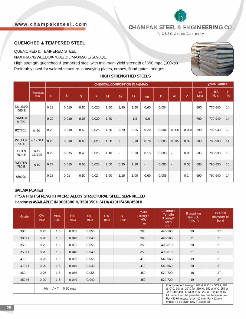
25
QUENCHED & TEMPERED STEEL
NAXTRA-70/WELDOX-700E/DILIMAX690 E/S690QL.
High strength quenched & tempered steel with minimum yield strength of 690 mpa (100ksi)
Preferably used for welded structure. conveying plates, cranes, flood gates, bridges
HIGH STRENGTHED STEELS
IMDILL AX690 E
NAXTRAM 700
RQT701
WELDOX 700 E
H L O C EMICA C MPOSITION IN % (MAX)
C SIS nM Ni rC Mo B
T p l luy ica Va es
sYMpa
SUTMpa
E%P Al V
0,18 0,010 0,50 0,020 1,60 1,80 1,50 0,60 0,004 690 770-940 14
0,20 0,010 0,08 0,020 1,60 - 1.5 0.6 700 770-940 14
0,20 0,010 0,50 0,025 1.60 0.70 0.25 0.20 0.004 0.006 0.008 690 790-930 18
0,20 0,010 0,60 0,020 1.60 2 0,70 0.70 0.005 0,015 0,09 700 780-930 14
0.20 0.015 0.40 0.025 1.40 - 0.20 0.15 0.005 - 0.08 685 780-930 16
0.22 0.015 0.55 0.025 2.00 0.30 1.20 - 0.005 - 0.05 685 780-930 16
0.18 0.01 0.50 0.02 1.60 1.15 1.00 0.60 0.005 - 0.1 690 790-940 14
QUENCHED & TEMPERED STEEL
Thickn ssemm
8 -30
4,0 - 50,1
H ENIT 780 L E
6-1919.1-32
WE ELT N 0 78 E
9S6 0QL
6-50
SAILMA PLATES
IT'S A HIGH STRENGTH MICRO ALLOY STRUCTURAL STEEL SEMI-KILLED
Hardness AVAILABLE IN 300/300HI/350/350HI/410/410HI/450/450HI
0Charpy lmpact energy : 40J at 0 C for 300HI, 40J0 0 0at 0 C, 30j at -20 C for 350 HI, 35J at 0 C, 25J at
0 0 0-20 C for 410 HI, 3J at 0 C , 20J at -20 C for 450HI. Impact will be given for any one temperature.For 450 HI impact is for >10 mm. For <12 mmimpact to be given only if specified.
Nb = V + Ti = 0.30 max
300 0.25 1.5 0.055 0.055 300 440-560 20 3T
300 Hi 0.20 1.5 0.040 0.040 300 440-560 21 3T
350 0.25 1.5 0.055 0.055 350 490-610 20 3T
350 Hi 0.20 1.5 0.040 0.040 350 490-610 21 3T
410 0.25 1.5 0.055 0.055 410 540-660 19 3T
410 Hi 0.20 1.5 0.040 0.040 410 540-660 20 3T
450 0.25 1.5 0.055 0.055 450 570-720 18 3T
450 Hi 0.20 1.5 0.040 0.040 450 570-720 19 3T
Grade C%max
Mn%max
P%max
S%max
Si%max
CEmax
Internaldiameter of
bend
ultimateTensile
StrengthMPa min
Elongation%min GL5.65 S
YieldStrength
MPamin
w w w . c h a m p a k s t e e l . c o m
A C S E C G r o u p C o m p a n y
CHAMPAK STEEL & ENGINEERING CO .CHAMPAK STEEL & ENGINEERING CO .CHAMPAK STEEL & ENGINEERING CO .CHAMPAK STEEL & ENGINEERING CO .
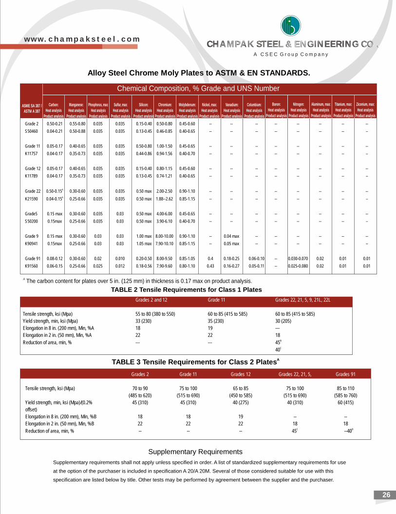
Grade 2 0.50-0.21 0.55-0.80 0.035 0.035 0.15-0.40 0.50-0.80 0.45-0.60 -- -- -- -- -- -- -- --
S50460 0.04-0.21 0.50-0.88 0.035 0.035 0.13-0.45 0.46-0.85 0.40-0.65 -- -- -- -- -- -- -- –
Grade 11 0.05-0.17 0.40-0.65 0.035 0.035 0.50-0.80 1.00-1.50 0.45-0.65 -- -- -- -- -- -- -- --
K11757 0.04-0.17 0.35-0.73 0.035 0.035 0.44-0.86 0.94-1.56 0.40-0.70 -- -- -- -- -- -- -- –
Grade 12 0.05-0.17 0.40-0.65 0.035 0.035 0.15-0.40 0.80-1.15 0.45-0.60 -- -- -- -- -- -- -- --
K11789 0.04-0.17 0.35-0.73 0.035 0.035 0.13-0.45 0.74-1.21 0.40-0.65 -- -- -- -- -- -- -- –
AGrade 22 0.50-0.15 0.30-0.60 0.035 0.035 0.50 max 2.00-2.50 0.90-1.10 -- -- -- -- -- -- -- --AK21590 0.04-0.15 0.25-0.66 0.035 0.035 0.50 max 1.88--2.62 0.85-1.15 -- -- -- -- -- -- -- –
Grade5 0.15 max 0.30-0.60 0.035 0.03 0.50 max 4.00-6.00 0.45-0.65 -- -- -- -- -- -- -- --
S50200 0.15max 0.25-0.66 0.035 0.03 0.50 max 3.90-6.10 0.40-0.70 -- -- -- -- -- -- -- –
Grade 9 0.15 max 0.30-0.60 0.03 0.03 1.00 max 8.00-10.00 0.90-1.10 -- 0.04 max -- -- -- -- -- --
K90941 0.15max 0.25-0.66 0.03 0.03 1.05 max 7.90-10.10 0.85-1.15 -- 0.05 max -- -- -- -- -- –
Grade 91 0.08-0.12 0.30-0.60 0.02 0.010 0.20-0.50 8.00-9.50 0.85-1.05 0.4 0.18-0.25 0.06-0.10 -- 0.030-0.070 0.02 0.01 0.01
K91560 0.06-0.15 0.25-0.66 0.025 0.012 0.18-0.56 7.90-9.60 0.80-1.10 0.43 0.16-0.27 0.05-0.11 -- 0.025-0.080 0.02 0.01 0.01
26
Supplementary Requirements
Supplementary requirements shall not apply unless specified in order. A list of standardized supplementary requirements for use
at the option of the purchaser is included in specification A 20/A 20M. Several of those considered suitable for use with this
specification are listed below by title. Other tests may be performed by agreement between the supplier and the purchaser.
A The carbon content for plates over 5 in. (125 mm) in thickness is 0.17 max on product analysis.
Carbon:
Heat analysis
Product analysis
Manganese:
Heat analysis
Product analysis
Phosphorus, max:
Heat analysis
Product analysis
Sulfur, max:
Heat analysis
Product analysis
Silicon:
Heat analysis
Product analysis
Chromium:
Heat analysis
Product analysis
Molybdenum:
Heat analysis
Product analysis
Nickel, max:
Heat analysis
Product analysis
Vanadium:
Heat analysis
Product analysis
Columbium:
Heat analysis
Product analysis
Boron:
Heat analysis
Product analysis
Nitrogen:
Heat analysis
Product analysis
Aluminum, max:
Heat analysis
Product analysis
Titanium, max:
Heat analysis
Product analysis
Ziconium, max:
Heat analysis
Product analysis
Chemical Composition, % Grade and UNS Number
ASME SA 387 / ASTM A 387
Alloy Steel Chrome Moly Plates to ASTM & EN STANDARDS.
TABLE 2 Tensile Requirements for Class 1 Plates
ATABLE 3 Tensile Requirements for Class 2 Plates
Grades 2 Grade 11 Grades 12 Grades 22, 21, 5, Grades 91
Tensile strength, ksi (Mpa) 70 to 90 75 to 100 65 to 85 75 to 100 85 to 110
(485 to 620) (515 to 690) (450 to 585) (515 to 690) (585 to 760)
Yield strength, min, ksi (Mpa)/(0.2% 45 (310) 45 (310) 40 (275) 40 (310) 60 (415)
offset)
Elongation in 8 in. (200 mm), Min, %B 18 18 19 -- --
Elongation in 2 in. (50 mm), Min, %B 22 22 22 18 18C DReduction of area, min, % -- -- -- 45 --40
Grades 2 and 12 Grade 11 Grades 22, 21, 5, 9, 21L, 22L
Tensile strength, ksi (Mpa) 55 to 80 (380 to 550) 60 to 85 (415 to 585) 60 to 85 (415 to 585)
Yield strength, min, ksi (Mpa) 33 (230) 35 (230) 30 (205)
Elongation in 8 in. (200 mm), Min, %A 18 19 ---
Elongation in 2 in. (50 mm), Min, %A 22 22 18BReduction of area, min, % --- --- 45C40
w w w . c h a m p a k s t e e l . c o m
A C S E C G r o u p C o m p a n y
CHAMPAK STEEL & ENGINEERING CO .CHAMPAK STEEL & ENGINEERING CO .CHAMPAK STEEL & ENGINEERING CO .CHAMPAK STEEL & ENGINEERING CO .
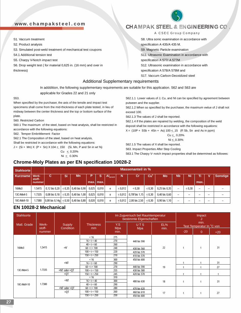
S1. Vaccum treatment
S2. Product analysis
S3. Simulated post-weld treatment of mechanical test coupons
S4.1 Additional tension test
S5. Charpy V-Notch impact test
S6. Drop weight test ( for material 0,625 in. (16 mm) and over in
thickness)
S8. Ultra sonic examination in accordance with
specification A 435/A 435 M.
S9. Magnetic Particle examination
S11. Ultrasonic Examination in accordance with
specification A 577/ A 577M
S12. Ultrasonic examination in accordance with
specification A 578/A 578M and
S17. Vaccum Carbon-Deoxidized steel
Additional Supplementary requirements
In adddition, the following supplementary requirements are suitable for this application. S62 and S63 are
applicable for Grades 22 and 21 only
S53.
When specified by the purchaser, the axis of the tensile and impact test
specimens shall come from the mid-thickness of each plate tested, in lieu of
midway between the center thickness and the top or bottom surface of the
plate.
S60. Restricted Carbon
S60.1 The maximum of the steel, based on heat analysis, shall be restricted in
accordance with the following equations:
S62. Temper Embrittlement Factor
S62.1 The Composition of the steel, based on heat analysis,
Shall be restricted in accordance with the following equations:
J = (Si + Mn) X (P + Sn) X 104 < 150 (Si, Mn, P and Sn in wt %)
Cu < 0.20%
Ni < 0.30%
S62.1.1 Lower values of J, Cu, and NI can be specified by agreement between
putween and the supplier.
S62.1.2 When so specified by the purchaser, the maximum vwlue of J shall not
exceed 100.
S62.1.3 The values of J shall be reported.
S62.1.4 If the plates are repaired by welding, the composition of the weld
deposit shall be restricted in accordance with the following equations:
X = (10P + 5Sb + 4Sn + As) 100 < 15 (P, Sb, Sn and As in ppm)
Cu < 0.20%
Ni < 0.30%
S62.1.5 The values of X shall be reported.
S63. Impact Properties After Step Cooling
S63.1 The Charpy V- notch impact properties shall be determined as followes:
Chrome-Moly Plates as per EN specification 10028-2
EN 10028-2 Mechanical
Massenanteil in %Stahlsorte
Kurzname Werk-stoff-nummer
C Si Mn P
max.
S
max.
Algesamt N Cr bCu Mo Nb Ti
max.
V SonstigeNi
16Mo3 1.5415 0,12 bis 0,20 < 0,35 0,40 bis 0,90 0,025 0,010 e < 0,012 < 0,30 < 0,30 0,25 bis 0,35 -- < 0,30 -- -- --
13CrMo4-5 1.7335 0,08 bis 0,18 < 0,35 0,40 bis 1,00 0,025 0,010 e < 0,012 0,70f bis 1,15 < 0,30 0,40 bis 0,60 -- -- -- -- --
10CrMo9-10 1.7380 0,08 bis 0,14g < 0,50 0,40 bis 0,80 0,020 0,010 e < 0,012 2,00 bis 2,50 < 0,30 0,90 bis 1,10 -- -- -- -- –
27
Stahlsorte
Matl. Grade Werk-stoff-nummer
SupplyCondition
Thicknessmm
Im Zugversuch bel Raumtemperaturbestimmte Elgenschaften
Y.SMpamin.
U T SMpa
EL%min.
ImpactJ
min.OTest Temperatur In C von
-20 0 +20
16Mo3 1,5415 e+N
< 16
16 < t < 40
40 < t < 60
60 < t < 100
100 < t < 150
150 < t < 250
275
270
260
240
220
210
440 bis 590
430 bis 560
420 bis 570
410 bis 570
22 t t 31
13CrMo4-5 1.7335
+NT
+NT oder +QT+QT
< 16
16 < t < 60
60 < t < 100
100 < t < 150
150 < t < 250
300
290
270
255
245
450 bis 600
440 bis 590
430 bis 580
420 bis 570
19 t t 27
t t 31
t t t
10CrMo9-10 1.7380
+NT
+NT oder +QT
+QT
< 16
16 < t < 40
40 < t < 60
60 < t < 100
100 < t < 150
150 < t < 250
310
300
290
280
260
250
480 bis 630
470 bis 620
460 bis 610
450 bis 600
18 t t 31
t t 2717
w w w . c h a m p a k s t e e l . c o m
A C S E C G r o u p C o m p a n y
CHAMPAK STEEL & ENGINEERING CO .CHAMPAK STEEL & ENGINEERING CO .CHAMPAK STEEL & ENGINEERING CO .CHAMPAK STEEL & ENGINEERING CO .
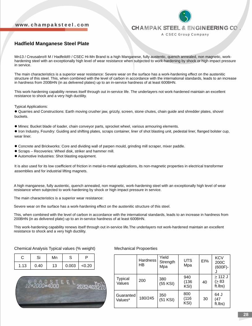
28
Hadfield Manganese Steel Plate
Mn13 / Creusabro® M / Hadfeild® / CSEC Hi-Mn Brand is a high Manganese, fully austentic, quench annealed, non magnetic, work-hardening steel with an exceptionally high level of wear resistance when subjected to work-hardening by shock or high impact pressure in service.
The main characteristics is a superior wear resistance: Severe wear on the surface has a work-hardening effect on the austenitic structure of this steel. This, when combined with the level of carbon in accordance with the international standards, leads to an increase in hardness from 200BHN (in as delivered plates) up to an in-service hardness of at least 600BHN.
This work-hardening capability renews itself through out in-service life. The underlayers not work-hardened maintain an excellent resistance to shock and a very high ductility.
Typical Applications:
l Quarries and Constructions: Earth moving crusher jaw, grizzly, screen, stone chutes, chain guide and shredder plates, shovel
buckets.
l Mines: Bucket blade of loader, chain conveyor parts, sprocket wheel, various armouring elements.
l Iron Industry, Foundry: Guiding and shifting plates, scraps container, liner of shot blasting unit, pedestal liner, flanged bolster cup,
wear liner.
l Concrete and Brickworks: Core and dividing wall of parpen mould, grinding mill scraper, mixer paddle.
l Scraps – Recoveries: Wheel disk, striker and hammer mill.
l Automotive Industries: Shot blasting equipment.
It is also used for its low coefficient of friction in metal-to-metal applications, its non-magnetic properties in electrical transformer
assemblies and for industrial lifting magnets.
Chemical Analysis Typical values (% weight) Mechanical Propoerties
C Si Mn S P
1.13 0.40 13 0.003 <0.20
HardnessHB
YieldStrengthMpa
UTSMpa
EI%KCV200C(600F)-J
TypicalValues
200 380(55 KSI)
940(136 KSI)
40
> 112 J(> 83ft.lbs)
GuarantedValues* 180/245
350(51 KSI)
800(116 KSI)
30 64 J(47ft.lbs)
A high manganese, fully austentic, quench annealed, non magnetic, work-hardening steel with an exceptionally high level of wear resistance when subjected to work-hardening by shock or high impact pressure in service.
The main characteristics is a superior wear resistance:
Severe wear on the surface has a work-hardening effect on the austenitic structure of this steel.
This, when combined with the level of carbon in accordance with the international standards, leads to an increase in hardness from 200BHN (in as delivered plate) up to an in-service hardness of at least 600BHN.
This work-hardening capability renews itself through out in-service life.The underlayers not work-hardened maintain an excellent resistance to shock and a very high ductility.
w w w . c h a m p a k s t e e l . c o m
A C S E C G r o u p C o m p a n y
CHAMPAK STEEL & ENGINEERING CO .CHAMPAK STEEL & ENGINEERING CO .CHAMPAK STEEL & ENGINEERING CO .CHAMPAK STEEL & ENGINEERING CO .
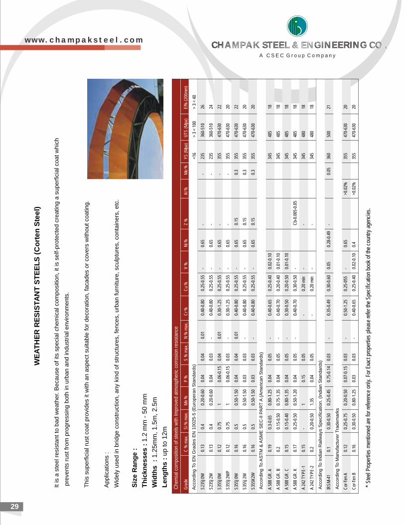
WE
AT
HE
R R
ES
ISTA
NT
ST
EE
LS
(C
ort
en
Ste
el)
It is
a s
tee
l re
sist
an
t to
ba
d w
ea
the
r. B
eca
use
of its
sp
eci
al c
he
mic
al c
om
po
sitio
n, it
is s
elf-
pro
tect
ed
cre
atin
g a
su
pe
rfic
ial c
oa
t w
hic
h
pre
ven
ts r
ust
fro
m p
rog
ress
ing
bo
th in
urb
an
an
d in
du
stria
l en
viro
nm
en
ts.
Th
is s
up
erf
icia
l ru
st c
oa
t p
rovi
de
s it
with
an
asp
ect
su
itab
le fo
r d
eco
ratio
n, fa
cad
es
or
cove
rs w
itho
ut co
atin
g.
Ap
plic
atio
ns
:
Wid
ely
use
d in
brid
ge
co
nst
ruct
ion
, a
ny
kin
d o
f st
ruct
ure
s, fe
nce
s, u
rba
n fu
rnitu
re, sc
ulp
ture
s, c
on
tain
ers
, e
tc.
Siz
e R
an
ge
:
Th
ick
ne
ss
es
: 1
.2 m
m -
50
mm
Wid
ths
:
1.2
5m
m, 1
.5m
, 2
.5m
Le
ng
ths
: u
p to
12
m
Che
mia
l com
posi
tion
of s
teel
s w
ith Im
prov
ed a
tmos
pher
ic c
orro
sion
res
ista
nce
* S
teel
Pro
pert
ies
men
tione
d ar
e fo
r re
fere
nce
only
. For
Exa
ct p
rope
rtie
s pl
ease
refe
r th
e S
peci
ficat
ion
book
of t
he c
ount
ry a
genc
ies.
29
Acc
ord
ing
To
AS
TM
& A
SM
E S
EC
-ll P
AR
T A
(A
me
rica
n S
tan
da
rds)
Acc
ord
ing
To
In
dia
n R
ailw
ays
Sp
eci
fica
tion
. (I
nd
ian
Sta
nd
ard
s)
Acc
ord
ing
To
Ma
nu
fact
ure
r T
rad
em
ark
s
Acc
ord
ing
To
EN
Gra
de
s E
N 1
00
25
-5 (
Eu
rop
era
n S
tan
da
rds)
Gra
deC
% m
ax.
Si %
max
.M
n %
P %
S %
max
.N
% m
ax.
Cr
%
Cu
%
V %
N
i %
Z %
A
l %
Mo
%
YS
(M
pa)
UT
S (
Mpa
)E
l% (
200m
m)
<16
> 3
< 10
0>
3 <
40
S23
5J0W
0.13
0.4
0.20
-0.6
00.
040.
040.
010.
40-0
.80
0.25
-0.5
5-
0.65
--
235
360-
510
26
S23
5J2W
0.13
0.4
0.20
-0.6
00.
040.
03-
0.40
-0.8
00.
25-0
.55
-0.
65-
-23
536
0-51
024
S35
5J0W
0.12
0.75
10.
06-0
.15
0.04
0.01
0.30
-1.2
50.
25-0
.55
-0.
65-
-35
547
0-63
022
S35
5J2W
P0.
120.
751
0.06
-0.1
50.
03-
0.30
-1.2
50.
25-0
.55
-0.
65-
-35
547
0-63
020
S35
5J0W
0.16
0.5
0.50
-1.5
00.
040.
040.
010.
40-0
.80
0.25
-0.5
5-
0.65
0.15
0.3
355
470-
630
22
S35
5J2W
0.16
0.5
0.50
-1.5
00.
030.
03-
0.40
-0.8
00.
25-0
.55
-0.
650.
150.
335
547
0-63
020
S35
5K2W
0.16
0.5
0.50
-1.5
00.
030.
03-
0.40
-0.8
00.
25-0
.55
-0.
650.
150.
335
547
0-63
020
A 5
88 G
R. A
0.19
0.3-
0.65
0.80
-1.2
50.
040.
05-
0.40
-0.6
50.
25-0
.40
0.02
-0.1
034
548
518
A 5
88 G
R. B
0.2
0.15
-0.5
00.
75-1
.35
0.04
0.05
-0.
40-0
.70
0.20
-0.4
00.
01-0
.10
345
485
18
A 5
88 G
R. C
0.15
0.15
-0.4
00.
80-1
.35
0.04
0.05
-0.
30-0
.50
0.20
-0.5
00.
01-0
.10
345
485
18
A 5
88 G
R. K
0.17
0.25
-0.5
00.
50-1
.20
0.04
0.05
-0.
40-0
.70
0.30
-0.5
0-
Cb-
0.00
5-0.
0534
548
518
A 2
42 T
YP
E-1
0.15
-1
0.15
0.05
-0.
20 m
in-
-34
548
018
A 2
42 T
YP
E-2
0.2
0.20
-0.5
01.
350.
040.
05-
0.20
min
--
345
480
18
IRS
M-4
10.
10.
30-0
.50
0.25
-0.4
50.
75-0
.14
0.03
-0.
35-0
.49
0.30
-0.6
00.
050.
28-0
.49
-0.
0536
050
021
Cor
-Ten
A0.
120.
25-0
.75
0.20
-0.5
00.
07-0
.15
0.03
-0.
50-1
.25
0.25
-055
-0.
65>0
.02%
355
470-
630
20
Cor
-Ten
B0.
160.
30-0
.50
0.80
-1.2
50.
030.
03-
0.40
-0.6
50.
25-0
.40
0.02
-0.1
00.
4>0
.02%
355
470-
630
20
w w w . c h a m p a k s t e e l . c o m
A C S E C G r o u p C o m p a n y
CHAMPAK STEEL & ENGINEERING CO .CHAMPAK STEEL & ENGINEERING CO .CHAMPAK STEEL & ENGINEERING CO .CHAMPAK STEEL & ENGINEERING CO .
STAINLESS STEEL, ALLOY STEEL& EN SERIES RODS
w w w . c h a m p a k s t e e l . c o m 30
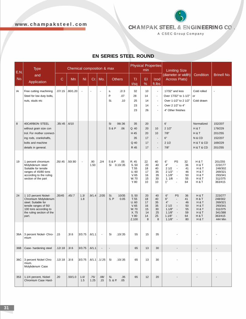
31
IA Free cutting machining .07/.15 .80/1.20 - - - s. .2/.3 32 10 - 17/32” and less Cold rolled -
Steel for low duty bolts, P. .07 28 14 - Over 17/32” to 1-1/2” or
nuts, studs etc Si. .10 25 14 - Over 1-1/2” to 2 1/2” Cold drawn
23 14 - Over 2 1/2” to 4”
23 26 - 4” Other finishes
8 40CARBON STEEL .35/.45 .6/10 Si 06/.36 35 20 6’ Normalized 152/207
without grain size con S & P .06 Q 40 20 10 2 1/2” H & T 179/229
trol. For mother connect- H 45 20 10 7/8” H & T 201/255
ing rods, crankshafts, 35 17 - 6” N & CD 152/207
bolts and machine Q 40 17 - 2 1/2 H & T & CD 169/229
details in general. R 45 17 - 7/8” H & T & CD 201/255
E.N.
No.
Type
and
ApplicationC Mn Ni Cr. Mo. Others T.I EI Izod
t/sq % ft.lbs
Chemical composition & maxPhysical Properties
min Limiting Size(diameter or width) Condition Brinell No.
Across Plats)
EN SERIES STEEL ROUND
19 1 percent chromium .35/.45 .50/.80 - .90 .2/4 S & P .05 R. 45 22 40 6” PS 32 H & T 201/255Molybdenum steel 1.50 Si 0.10/.35 S. 50 20 40 4” - 36 H & T 223/177Suitable for tensile T. 55 18 40 2 1/2 - 41 H & T 248/302ranges of 45/80 tons U. 60 17 35 2 1/2” - 46 H & T 269/321according to the ruling V. 65 16 35 1.1/8” - 50 H & T 293/341section of the part W. 70 15 30 1. 1/8 - 55 H & T 311/375
Y. 80 10 10 1” - 64 H & T 363/415
24 1 1/2 percent Nickel- .35/45 .45/.7 1.3/ .9/1.4 .2/35 Si. 10/35 S. 50 20 40 6” PS 36 H & T 223/277Chromium Molybdenum 1.8 S. P 0.05 T. 55 18 40 6” - 41 H & T 248/302steel. Suitable for U. 60 17 35 4” - 46 H & T 269/321tensile ranges of 50/ V. 65 16 35 2 1/2 - 50 H & T 293/341100 tons according to W. 70 15 30 1.1/8” - 55 H & T 311/375the ruling section of the X. 75 14 25 1.1/8” - 59 H & T 341/388part. Y. 80 14 25 1.1/8” - 64 H & T 363/415
Z.100 8 8 1.1/8” - 80 H & T 444 Min
36A 3 percent Nickel- Chro- .15 .3/.6 3/3.75 .6/1.1 - Si .10/.35 55 15 35 - - -mium
36B Case- hardening steel .12/.18 .3/.6 3/3.75 .6/1.1 - - 65 13 30 - - -
36C 3 percent Nickel Chro .12/.18 .3/.6 3/3.75 .6/1.1 .1/.25 Si .10/.35 65 13 30 - - -mium.Molybdenum Case
353 1.1/4 percent, Nickel .20 .50/1.0 1.0/ .75/ .08/ Si. .35 65 12 20 - - -Chromium Case Hard- 1.5 1.25 .15 S. & P. .05
w w w . c h a m p a k s t e e l . c o m
A C S E C G r o u p C o m p a n y
CHAMPAK STEEL & ENGINEERING CO .CHAMPAK STEEL & ENGINEERING CO .CHAMPAK STEEL & ENGINEERING CO .CHAMPAK STEEL & ENGINEERING CO .
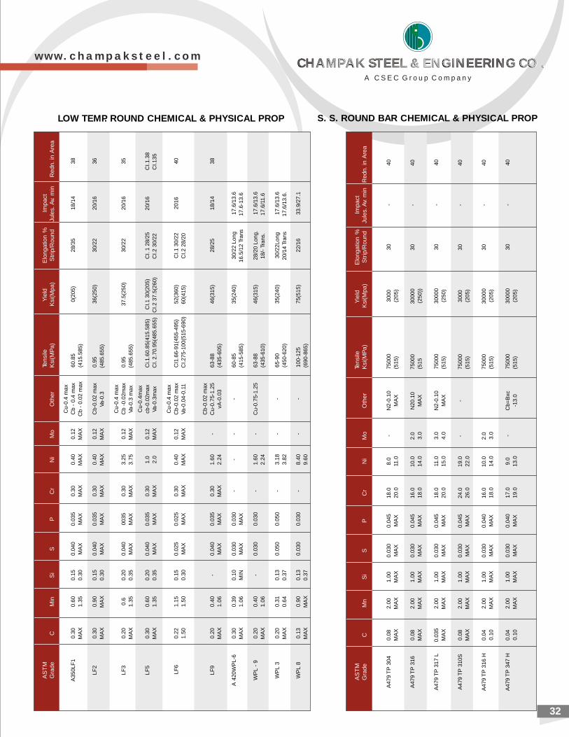
32
LOW TEMP. ROUND CHEMICAL & PHYSICAL PROP S. S. ROUND BAR CHEMICAL & PHYSICAL PROP
AS
TM
Tens
ileY
ield
Elo
ngat
ion
%Im
pact
Gra
deC
Min
Si
SP
Cr
Ni
Mo
Oth
erK
si(M
Pa)
Ksi
(Mpa
)S
trip
/Rou
ndJu
les.
Av.
min
R
edn.
in A
rea
Cu-
0.4
max
A35
0LF
10.
300.
600.
150.
040
0.03
50.
300.
400.
12C
b -
0.4
max
60.8
50(
205)
28/3
518
/14
38M
AX
1.35
0.30
MA
XM
AX
MA
XM
AX
MA
XC
b -
0.02
max
(415
.585
)
LF2
0.30
0.90
0.15
0.04
00.
035
0.30
0.40
0.12
Cb-
0.02
max
0.95
36(2
50)
30/2
220
/16
36M
AX
MA
X0.
30M
AX
MA
XM
AX
MA
XM
AX
Va-0
.3(4
85.6
55)
Cu-
0.4
max
LF3
0.20
0.6
0.20
0.04
000
350.
303.
250.
12C
b -0
.02m
ax0.
9537
.5(2
50)
30/2
220
/16
35M
AX
1.35
0.35
MA
XM
AX
MA
X3.
75M
AX
Va-0
.3 m
ax(4
85.6
55)
Cu-
0.4m
axLF
50.
300.
600.
200.
040
0.03
50.
301.
00.
12cb
-0.0
2max
Ci.1
.60.
85(4
15.5
85)
CI.1
30(
205)
CI.
1 28
/25
20/1
6C
I.1.3
8M
AX
1.35
0.35
MA
XM
AX
MA
X2.
0M
AX
Va-0
.3m
axC
I. 2.
70.9
5(48
5.65
5)C
I.2 3
7.5(
260)
CI.2
30/
22C
I.135
Cu-
0.4
max
LF6
0.22
1.15
0.15
0.02
50.
025
0.30
0.40
0.12
Cb-
0.02
max
CI1
.66-
91(4
55-4
95)
52(3
60)
CI.1
30/
2220
1640
1.50
1.50
0.30
MA
XM
AX
MA
XM
AX
MA
XVa
-0.0
4-0.
11C
I.275
-100
(515
-690
)60
(415
)C
I.2 2
8/20
Cb-
0.02
max
LF9
0.20
0.40
-0.
040
0.03
50.
301.
60-
Cu-
0.75
-1.2
563
-88
46(3
15)
28/2
518
/14
38M
AX
1.06
MA
XM
AX
MA
X2.
24vA
-0.0
3(4
35-6
05)
A 4
20W
PL-
60.
300.
390.
100.
030
0.03
0-
--
-60
-85
35(2
40)
30/2
2 Lo
ng17
.6/1
3.6
MA
X1.
06M
INM
AX
MA
X(4
15-5
85)
16.5
/12
Tran
s17
.6-1
3.6
WP
L -
90.
200.
40-
0.03
00.
030
-1.
60-
Cu-
0.75
-1.2
563
-88
46(3
15)
28/2
0 Lo
ng.
17.6
/13.
6M
AX
1.06
2.24
(435
-610
)18
/- T
rans
.17
.6/1
1.6
WP
L 3
0.20
0.31
0.13
0.05
00.
050
-3.
18-
-65
-90
35(2
40)
30/2
2Lon
g17
.6/1
3.6
MA
X0.
640.
373.
82(4
50-6
20)
20/1
4 Tr
ans
17.6
/13.
6.
WP
L 8
0.13
0.90
0.13
0.03
00.
030
-8.
40-
-10
0-12
575
(515
)22
/16
33.9
/27.
1M
AX
MA
X0.
379.
60(6
90-8
65)
AS
TM
Tens
ileY
ield
Elo
ngat
ion
%Im
pact
Gra
deC
Mn
Si
SP
Cr
Ni
Mo
Oth
erK
si(M
Pa)
Ksi
(Mpa
)S
trip
/Rou
ndJu
les.
Av.
min
Red
n. in
Are
a
A47
9 T
P 3
040.
082.
001.
000.
030
0.04
518
.08.
0-
N2-
0.10
7500
030
0030
-40
MA
XM
AX
MA
XM
AX
MA
X20
.011
.0M
AX
(515
)(2
05)
A47
9 T
P 3
160.
082.
001.
000.
030
0.04
516
.010
.02.
0N
20.1
075
000
3000
030
-40
MA
XM
AX
MA
XM
AX
MA
X18
.014
.03.
0M
AX
(515
(250
))
A47
9 T
P 3
17 L
0.03
52.
001.
000.
030
0.04
518
.011
.03.
0N
2-0.
1075
000
3000
030
-40
MA
XM
AX
MA
XM
AX
MA
X20
.015
.04.
0M
AX
(515
)(2
50)
A47
9 T
P 3
10S
0.08
2.00
1.00
0.03
00.
045
24.0
19.0
--
7500
030
0030
-40
MA
XM
AX
MA
XM
AX
MA
X26
.022
.0(5
15)
(205
)
A47
9 T
P 3
16 H
0.04
2.00
1.00
0.03
00.
040
16.0
10.0
2.0
7500
030
000
30-
400.
10M
AX
MA
XM
AX
MA
X18
.014
.03.
0(5
15)
(205
)
A47
9 T
P 3
47 H
0.04
2.00
1.00
0.03
00.
040
17.0
9.0
-C
b=B
xc75
000
3000
030
-40
0.10
MA
XM
AX
MA
XM
AX
19.0
13.0
-13.
0(5
15)
(205
)
w w w . c h a m p a k s t e e l . c o m
A C S E C G r o u p C o m p a n y
CHAMPAK STEEL & ENGINEERING CO .CHAMPAK STEEL & ENGINEERING CO .CHAMPAK STEEL & ENGINEERING CO .CHAMPAK STEEL & ENGINEERING CO .
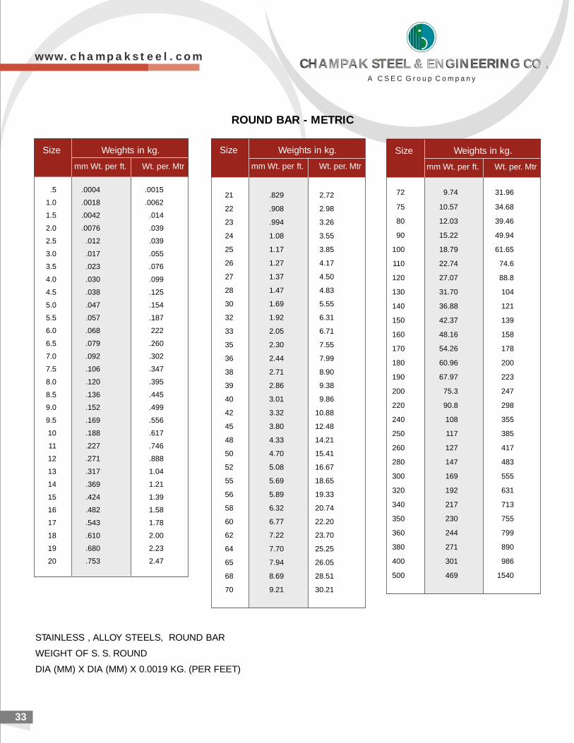
33
STAINLESS , ALLOY STEELS, ROUND BAR
WEIGHT OF S. S. ROUND
DIA (MM) X DIA (MM) X 0.0019 KG. (PER FEET)
Size Weights in kg.
mm Wt. per ft. Wt. per. Mtr
72 9.74 31.96
75 10.57 34.68
80 12.03 39.46
90 15.22 49.94
100 18.79 61.65
110 22.74 74.6
120 27.07 88.8
130 31.70 104
140 36.88 121
150 42.37 139
160 48.16 158
170 54.26 178
180 60.96 200
190 67.97 223
200 75.3 247
220 90.8 298
240 108 355
250 117 385
260 127 417
280 147 483
300 169 555
320 192 631
340 217 713
350 230 755
360 244 799
380 271 890
400 301 986
500 469 1540
Size Weights in kg.
mm Wt. per ft. Wt. per. Mtr
21 .829 2.72
22 .908 2.98
23 .994 3.26
24 1.08 3.55
25 1.17 3.85
26 1.27 4.17
27 1.37 4.50
28 1.47 4.83
30 1.69 5.55
32 1.92 6.31
33 2.05 6.71
35 2.30 7.55
36 2.44 7.99
38 2.71 8.90
39 2.86 9.38
40 3.01 9.86
42 3.32 10.88
45 3.80 12.48
48 4.33 14.21
50 4.70 15.41
52 5.08 16.67
55 5.69 18.65
56 5.89 19.33
58 6.32 20.74
60 6.77 22.20
62 7.22 23.70
64 7.70 25.25
65 7.94 26.05
68 8.69 28.51
70 9.21 30.21
Size Weights in kg.
mm Wt. per ft. Wt. per. Mtr
.5 .0004 .0015
1.0 .0018 .0062
1.5 .0042 .014
2.0 .0076 .039
2.5 .012 .039
3.0 .017 .055
3.5 .023 .076
4.0 .030 .099
4.5 .038 .125
5.0 .047 .154
5.5 .057 .187
6.0 .068 222
6.5 .079 .260
7.0 .092 .302
7.5 .106 .347
8.0 .120 .395
8.5 .136 .445
9.0 .152 .499
9.5 .169 .556
10 .188 .617
11 .227 .746
12 .271 .888
13 .317 1.04
14 .369 1.21
15 .424 1.39
16 .482 1.58
17 .543 1.78
18 .610 2.00
19 .680 2.23
20 .753 2.47
ROUND BAR - METRIC
w w w . c h a m p a k s t e e l . c o m
A C S E C G r o u p C o m p a n y
CHAMPAK STEEL & ENGINEERING CO .CHAMPAK STEEL & ENGINEERING CO .CHAMPAK STEEL & ENGINEERING CO .CHAMPAK STEEL & ENGINEERING CO .
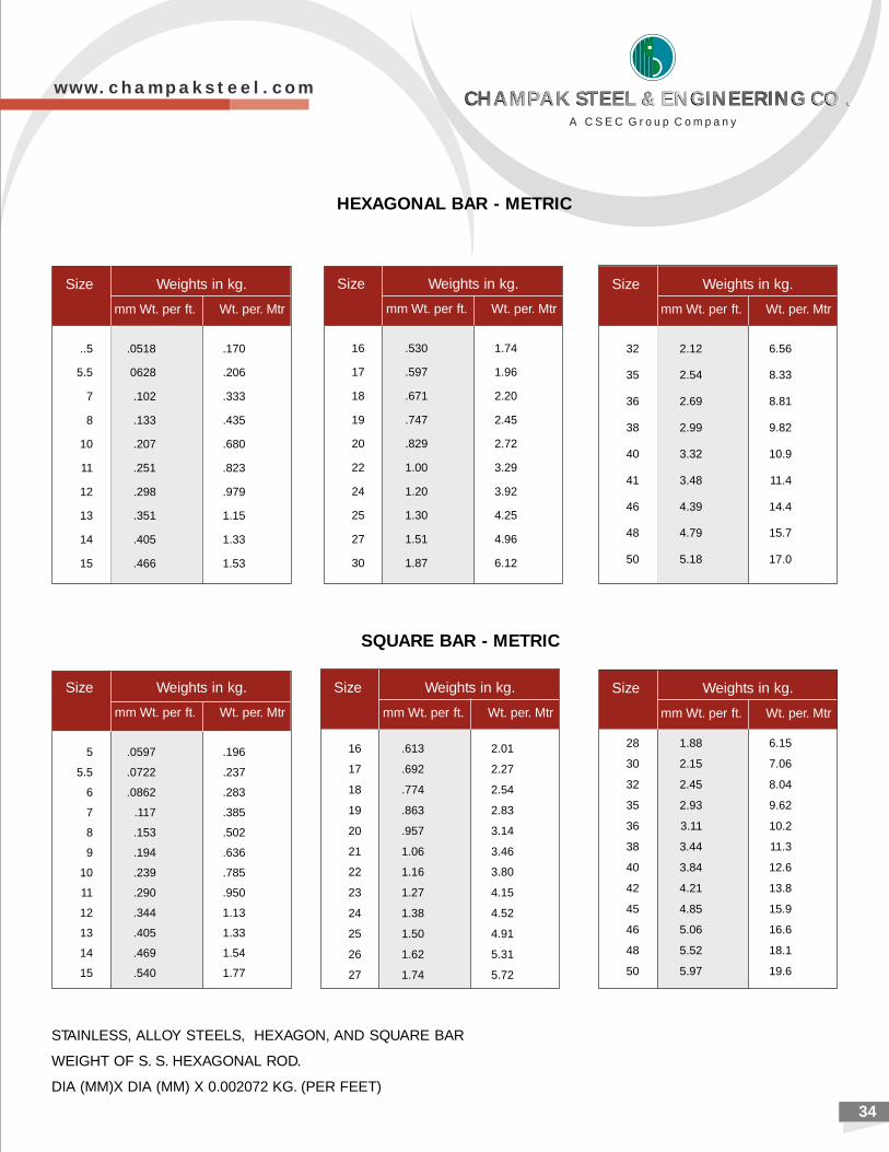
2034
STAINLESS, ALLOY STEELS, HEXAGON, AND SQUARE BAR
WEIGHT OF S. S. HEXAGONAL ROD.
DIA (MM)X DIA (MM) X 0.002072 KG. (PER FEET)
Size Weights in kg.
mm Wt. per ft. Wt. per. Mtr
..5 .0518 .170
5.5 0628 .206
7 .102 .333
8 .133 .435
10 .207 .680
11 .251 .823
12 .298 .979
13 .351 1.15
14 .405 1.33
15 .466 1.53
Size Weights in kg.
mm Wt. per ft. Wt. per. Mtr
16 .530 1.74
17 .597 1.96
18 .671 2.20
19 .747 2.45
20 .829 2.72
22 1.00 3.29
24 1.20 3.92
25 1.30 4.25
27 1.51 4.96
30 1.87 6.12
32 2.12 6.56
35 2.54 8.33
36 2.69 8.81
38 2.99 9.82
40 3.32 10.9
41 3.48 11.4
46 4.39 14.4
48 4.79 15.7
50 5.18 17.0
Size Weights in kg.
mm Wt. per ft. Wt. per. Mtr
5 .0597 .196
5.5 .0722 .237
6 .0862 .283
7 .117 .385
8 .153 .502
9 .194 .636
10 .239 .785
11 .290 .950
12 .344 1.13
13 .405 1.33
14 .469 1.54
15 .540 1.77
SQUARE BAR - METRIC
Size Weights in kg.
mm Wt. per ft. Wt. per. Mtr
28 1.88 6.15
30 2.15 7.06
32 2.45 8.04
35 2.93 9.62
36 3.11 10.2
38 3.44 11.3
40 3.84 12.6
42 4.21 13.8
45 4.85 15.9
46 5.06 16.6
48 5.52 18.1
50 5.97 19.6
Size Weights in kg.
mm Wt. per ft. Wt. per. Mtr
16 .613 2.01
17 .692 2.27
18 .774 2.54
19 .863 2.83
20 .957 3.14
21 1.06 3.46
22 1.16 3.80
23 1.27 4.15
24 1.38 4.52
25 1.50 4.91
26 1.62 5.31
27 1.74 5.72
HEXAGONAL BAR - METRIC
Size Weights in kg.
mm Wt. per ft. Wt. per. Mtr
w w w . c h a m p a k s t e e l . c o m
A C S E C G r o u p C o m p a n y
CHAMPAK STEEL & ENGINEERING CO .CHAMPAK STEEL & ENGINEERING CO .CHAMPAK STEEL & ENGINEERING CO .CHAMPAK STEEL & ENGINEERING CO .

2135
(Normal tee)
Common Grades IS 2062 E : 250 & S355J2H
Tolerance as per IS : 1852
Abbreviations used : DSM (Durgapur Section Mill)
BMM (Bhilai Merchant Mill)
BRSM (Bhilai Rail & structural Mill)
Thickness Weight Thickness Weight
Size Web Flange Meter Foot Size Web Flange Meter Foot
mm x mm mm mm kg Ib mm x mm mm mm kg Ib
INST ISDT (Deep Legged Tee)
20 20x20 3 3 0.9 0.60 100 100x50 5.8 10 8.7
150 150x75 8.0 11.6 15.7
20 20x20 4 4 1.1
30 30x30 3 3 1.4 0.9 ISLT
30 30X30 4 4 1.8 200 200X163 8.0 12.5 28.4
250 250X180 9.2 14.1 37.5
40 40x 40 6 6 3.5 2.35
50 50 x 50 6 6 5.4 3.63 ISHT (Slit Tee From H Section)
75 75x75 9 9 10.0 75 75x150 8.4 9.0 15.3 10.28
75 75x75 10 10 10.95 100 100x200 7.0 9.0 20.0 13.48
125 125x250 8.8 9.7 27.4 18.41
80 80x80 8 8 9.6 6.45 150 150x250 7.9 10.6 29.4 19.76
100 100x100 10 10 14.9
150 150x150 10 10 22.7
ANGLES (Equal)
Size in mm Weight kg/M Mill
ANGLES (equal)
50x50x6 4.5 BMM
65x65x6 5.8 BMM
65x65x8 7.7 BMM
65x65x10 9.4 BMM
75x75x6 6.8 BMM
75x75x8 8.9 BMM
75x75x10 11.0 BMM
80x80x6 7.3 BMM
80x80x8 9.6 BMM
80x80x10 11.8 BMM
90x90x6 8.2 BMM
90x90x8 10.8 BMM
90x90x10 13.4 BMM
100x100x8 12.1 DSM
100x100x10 14.9 DSM
100x100x12 17.7 DSM
110x110x10 16.6 DSM
110x110x12 19.7 DSM
130x130x10 19.7 DSM
130x130x12 23.4 DSM
150x150x16 35.8 BRSM
150x150x20 44.1 BRSM
200x200x16 48.5 BRSM
200x200x20 60.0 BRSM
Sides in Thickness W
mm 3 4 5 6 8 10 12 15 16 18 20
Equivalent
20 x 20mm 0.9 1.1
25 x 25 mm 1.1 1.4 1.8
30 x 30mm 1.4 1.8 2.2
35 x 35 mm 1.6 2.1 2.6 3.0
40 x 40 mm 1.8 2.4 3.0 3.5
45 x 45 mm 2.1 2.7 3.4 4.0
50 x 50 mm 2.3 3.0 3.8 4.5
55 x 55 mm 4.1 4.9 6.4 7.9
60 x 60 mm 4.5 5.4 7.0 8.6
65 x 65 mm 4.9 5.8 7.7 9.4
70 x 70 mm 5.3 6.3 8.3 10.2
75 x 75 mm 5.7 6.8 8.9 11.0
45 x 30 mm 1.7 2.2 2.8 3.3
75 x 50 mm 4.7 5.6 7.4 9.0
90 x 60 mm 6.8 8.9 11.0 13.0
100 x 75 mm 8.0 10.5 13.0 15.4
125 x 75 mm 9.2 12.1 14.9
125 x 95 mm 10.1 13.3 16.5 19.6
150 x 75 mm 13.7 16.9 20.1
150 x 115 mm 16.2 20.0 23.8 29.5
Desig-nation
Desig-nation
MILD STEEL & HIGH TENSILE ANGLES (Equal Sides) Angles (Equal and unequal Sides)
w w w . c h a m p a k s t e e l . c o m
A C S E C G r o u p C o m p a n y
CHAMPAK STEEL & ENGINEERING CO .CHAMPAK STEEL & ENGINEERING CO .CHAMPAK STEEL & ENGINEERING CO .CHAMPAK STEEL & ENGINEERING CO .
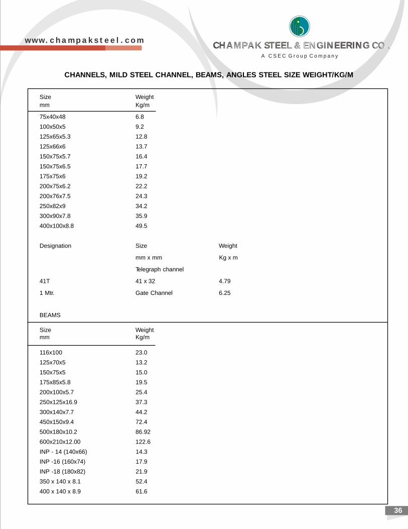
Size Weightmm Kg/m
75x40x48 6.8
100x50x5 9.2
125x65x5.3 12.8
125x66x6 13.7
150x75x5.7 16.4
150x75x6.5 17.7
175x75x6 19.2
200x75x6.2 22.2
200x76x7.5 24.3
250x82x9 34.2
300x90x7.8 35.9
400x100x8.8 49.5
Designation Size Weight
mm x mm Kg x m
Telegraph channel
41T 41 x 32 4.79
1 Mtr. Gate Channel 6.25
BEAMS
Size Weightmm Kg/m
116x100 23.0
125x70x5 13.2
150x75x5 15.0
175x85x5.8 19.5
200x100x5.7 25.4
250x125x16.9 37.3
300x140x7.7 44.2
450x150x9.4 72.4
500x180x10.2 86.92
600x210x12.00 122.6
INP - 14 (140x66) 14.3
INP -16 (160x74) 17.9
INP -18 (180x82) 21.9
350 x 140 x 8.1 52.4
400 x 140 x 8.9 61.6
CHANNELS, MILD STEEL CHANNEL, BEAMS, ANGLES STEEL SIZE WEIGHT/KG/M
36
w w w . c h a m p a k s t e e l . c o m
A C S E C G r o u p C o m p a n y
CHAMPAK STEEL & ENGINEERING CO .CHAMPAK STEEL & ENGINEERING CO .CHAMPAK STEEL & ENGINEERING CO .CHAMPAK STEEL & ENGINEERING CO .
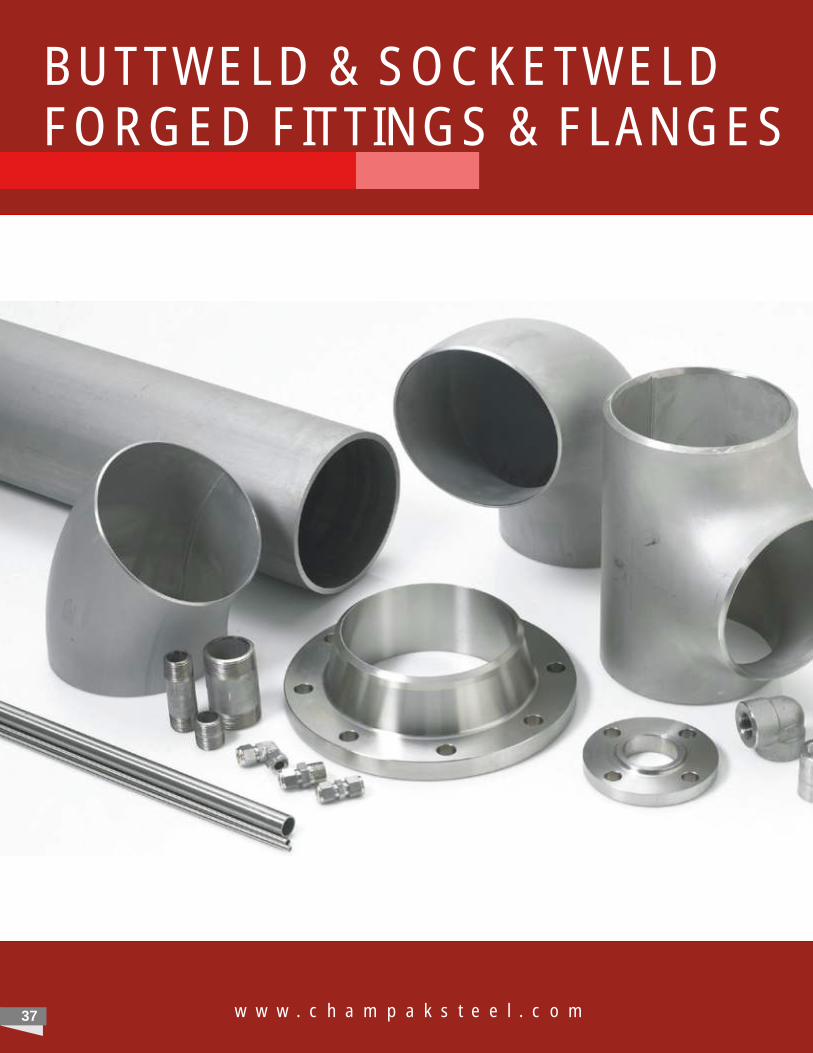
BUTTWELD & SOCKETWELD FORGED FITTINGS & FLANGES
w w w . c h a m p a k s t e e l . c o m37
38
Product Range
PIPE, PIPES FITTING LIKE ELBOW, TEE, REDUCER, STUBEND, COLLAR, CAP & FLANGE.
Material & Specification
Stainless Steel Pipe Fitting
Specification : ASTM A 403 & A 182, SMO254, 904L, 317L, 304L, 316L, 321H, 347H.
Duplex Pipe Fitting
Specification : Duplex SS - ASTM A744, A790,
With UNS S31803, S32205, S32750, S32760.
Carbon Steel Pipe Fitting (IBR & NON IBR)
Specification : A234-WPA, WPB, WPC & ASTM A105.
Alloy Steel Pipe Fitting
Specification : ASTM A182, A234 WP 5 / / WP 91/ WP 12 / WP 22
Inconel & Monel Pipe Fitting
Specification : Inconel 600/ 601/ 625- SB 366, ASTM B 366 Monel - 400.
Cupro Nickel Pipe Fitting
Specification : 90/ 10 CuNi UNS C 70600, 70/ 30 CuNi UNS C71500.
WP 11
w w w . c h a m p a k s t e e l . c o m
A C S E C G r o u p C o m p a n y
CHAMPAK STEEL & ENGINEERING CO .CHAMPAK STEEL & ENGINEERING CO .CHAMPAK STEEL & ENGINEERING CO .CHAMPAK STEEL & ENGINEERING CO .
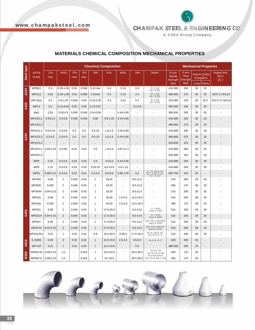
39
MATERIALS CHEMICAL COMPOSITION MECHANICAL PROPERTIES
Chemical Composition Mechanical Propertes
WPB(1) 0.3 0.29-1.06 0.05 0.058 0.10 min 0.4 0.15 0.4 415-585 240 30 20 -
WPC(1) 0.35 0.29-1.08 0.05 0.058 0.10min 0.4 0.15 0.4 485-655 275 30 20 -45*C 17.6/13.6
WPL/6(1) 0.3 0.6-1.35 0.035 0.04 0.15-0.30 0.3 0.12 0.4 415-585 240 30 16.5 -101*C 17.6/13.6
WPL3 0.2 0.31-0.64 0.05 0.05 0.13-0.37 - - 3.2-3.8 - 450-620 240 30 20 -
Wp1 0.28 0.30-0.9 0.045 0.045 0.10-0.50 - 0.44-0.65 - - 380-550 205 30 20 -
WP12CL1 0.05-0.2 0.3-0.8 0.045 0.045 0.60 0.8-1.25 0.44-0.65 - - 415-585 220 30 20 -
WP12CL2 - - - - - - - - - 485-655 275 30 20 -
WP11CL1 0.5-0.15 0.3-0.6 0.3 0.3 0.5-10 1.0-1.5 0.44-0.65 - - 415-585 205 30 20 -
WP11CL2 0.5-0.2 0.3-0.9 0.4 0.4 0.5-10 1.0-1.5 0.44-0.65 - - 485-655 275 30 20 -
WP11CL3 - - - - - - - - - 520-690 310 30 20 -
WP22CL1 0.05-0.15 0.3-06 0.04 0.04 0.5 1.9-2.6 0.87-11.3 - - 415-585 205 30 20 -
WP22CL3 - - - - - - - - - 520-690 310 30 20 -
WP5 0.15 0.3-0.6 0.04 0.03 0.5 4.0-6.0 0.44-0.65 - - 415-585 205 30 20 -
WP9 0.15 0.3-0.6 0.03 0.03 0.25-10 8.0-10.0 0.9-1.10 - - 415-585 205 30 20 -
WP91 0.08-0.12 0.3-0.6 0.02 0.01 0.2-0.5 8.0-9.5 0.85-1.05 0.4 585-760 415 20 - -
WP304 0.08 2 0.045 0.03 1 18.20 - 8.0-11.0 - 515 205 28 20 -
WP304L 0.035 2 0.045 0.03 1 18.20 - 8.0-13.0 - 485 170 28 20 -
WP304H 0.04-0.10 2 0.045 0.03 1 18.20 - 8.0-11.0 - 515 205 28 20 -
WP316 0.08 2 0.045 0.03 1 18.20 2.0-3.0 11.0-14.0 - 515 205 28 20 -
WP316L 0.035 2 0.045 0.03 1 18.20 2.0-3.0 10.0-16.0 - 485 170 28 20 -
WP321 0.08 2 0.045 0.03 1 17.0-20.0 - 9.0-13.0 515 205 28 20 -
WP321H 0.04-0.10 2 0.045 0.03 1 17.0-20.0 - 9.0-13.0 515 205 28 20 -
WP347 0.08 2 0.045 0.03 1 17.0-20.0 - 9.0-13.0 515 205 28 20 -
WP347H 0.04-0.10 2 0.045 0.03 1 17.0-20.0 - 9.0-13.0 515 205 28 20 -
WPS31254 0.02 1 0.03 0.01 0.8 19.5-20.5 6.06.5 17.5-18.5 515 205 28 20 -
S 31803 0.03 2 0.03 0.02 1 21.0-23.0 2.5-3.5 4.5-6.5 620 450 25 - -
WP 410 0.15 1 0.04 0.03 1 11.5-13.5 - 0.5 - 485-655 205 20 - -
WPNIC10 0.06-0.10 1.5 - 0.015 1 19.0-23.0 - 30.0-35.0 450 170 30 - -
WPNIC11 0.06-0.10 1.5 - 0.015 1 10.-23.0 - 30.0-35.0 450 170 30 - -
C u = 0 . 4V = 0 . 0 8
C b = 0 . 0 2
C u = 0 . 4V = 0 . 0 8
C b = 0 . 0 2
C u = 0 . 4V = 0 . 0 8
C b = 0 . 0 2
V = 0 . 1 8 - 0 . 2 5C b = 0 . 0 8 - 0 . 1 0N = 0 . 0 3 - 0 . 0 7
A I = 0 . 0 4
T I = 5 X Cm a x 0 . 7 0 %
T I = 4 X Cm a x 0 . 8 0 %
C b + Ta > = 1 0 X % Cm a x 0 . 1 0 %
C b + Ta > = 8 X % Cm a x 0 . 1 0 %
N = 0 . 1 8 - 0 . 2 2C u = 0 . 5 - 1 . 0
N = 0 . 8 - 0 . 2
C u = 0 . 7 5
A I = 0 . 1 5 - 0 . 6 0
F o = 3 9 . 5 m i n
A I + Ti = 0 . 8 5 - 1 . 2 0
ASTM C% Mn% P% S% Si% Cr% Mo% Ni% Others
Grade max max max
R.min
Tebsile
Strength
Mpa
S.min
Yiled
Strength
Mpa
A%min (2/4D)
Elongation
Impact test
RCV
(2) J
-Long Trabsv
B3
66
A
81
5 A
40
3 A
23
4 A
42
0 A
23
4 S
tee
l ty
pe
w w w . c h a m p a k s t e e l . c o m
A C S E C G r o u p C o m p a n y
CHAMPAK STEEL & ENGINEERING CO .CHAMPAK STEEL & ENGINEERING CO .CHAMPAK STEEL & ENGINEERING CO .CHAMPAK STEEL & ENGINEERING CO .
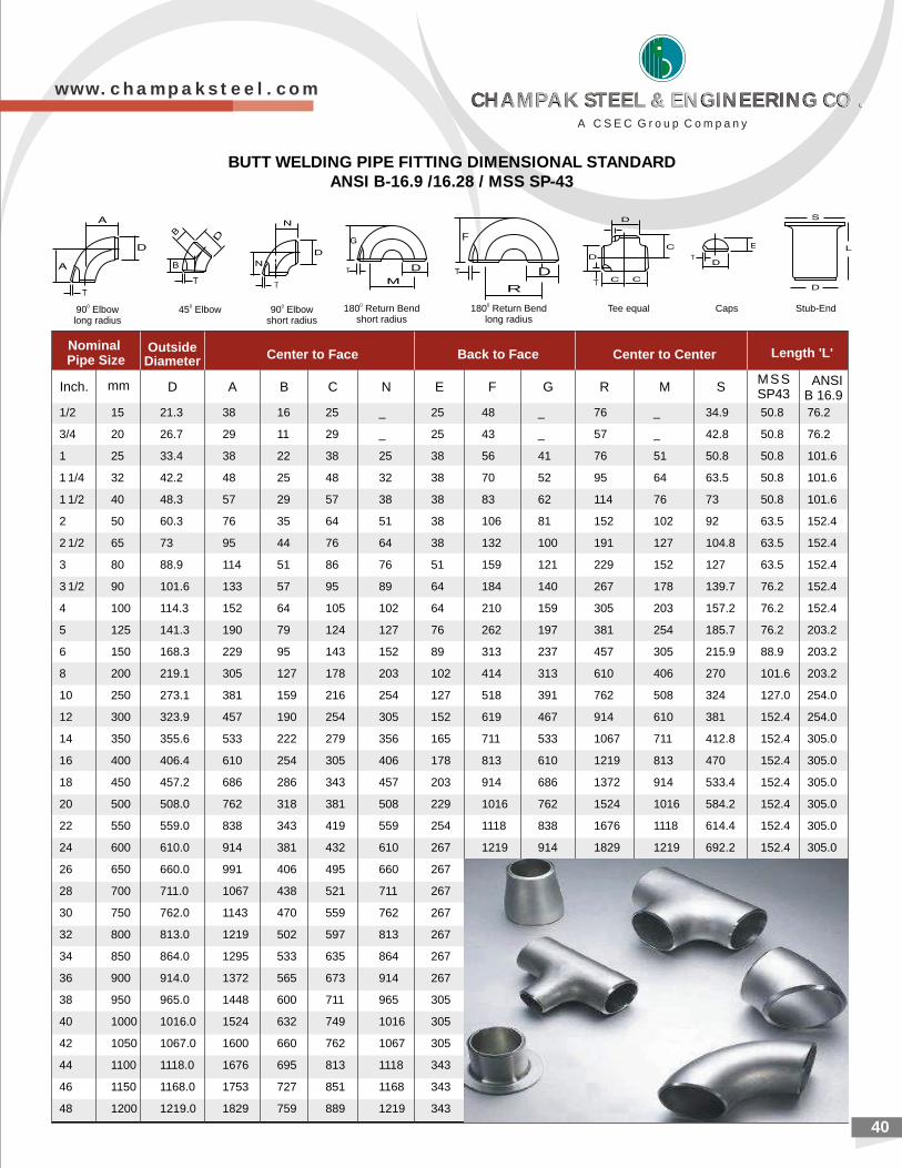
40
Inch. mm D A B C
090 Elbowlong radius
45 Elbow0
90 Elbowshort radius
0 180 Return short radius
0Bend
DT
F
R
180 Return Bendlong radius
0Tee equal Caps Stub-End
Nominal Pipe Size
OutsideDiameter
Center to Face Length 'L'Back to Face Center to Center
ANSIB 16.9
N E F G R M SM S SSP43
1/2 15 21.3 16 25 _ 25 48 _ 50.8 76.2
3/4 20 26.7 29 11 29 _ 25 43 _ 57 _ 42.8 50.8 76.2
1 25 33.4 38 22 38 25 38 56 41 76 51 50.8 50.8 101.6
1 1/4 32 42.2 48 25 48 32 38 70 52 95 64 63.5 50.8 101.6
1 1/2 40 48.3 57 29 57 38 38 83 62 114 76 73 50.8 101.6
2 50 60.3 76 35 64 51 38 106 81 152 102 92 63.5 152.4
2 1/2 65 73 95 44 76 64 38 132 100 191 127 104.8 63.5 152.4
3 80 88.9 114 51 86 76 51 159 121 229 152 127 63.5 152.4
3 1/2 90 101.6 133 57 95 89 64 184 140 267 178 139.7 76.2 152.4
4 100 114.3 152 64 105 102 64 210 159 305 203 157.2 76.2 152.4
5 125 141.3 190 79 124 127 76 262 197 381 254 185.7 76.2 203.2
6 150 168.3 229 95 143 152 89 313 237 457 305 215.9 88.9 203.2
8 200 219.1 305 127 178 203 102 414 313 610 406 270 101.6 203.2
10 250 273.1 381 159 216 254 127 518 391 762 508 324 127.0 254.0
12 300 323.9 457 190 254 305 152 619 467 914 610 381 152.4 254.0
14 350 355.6 533 222 279 356 165 711 533 1067 711 412.8 152.4 305.0
16 400 406.4 610 254 305 406 178 813 610 1219 813 470 152.4 305.0
18 450 457.2 686 286 343 457 203 914 686 1372 914 533.4 152.4 305.0
20 500 508.0 762 318 381 508 229 1016 762 1524 1016 584.2 152.4 305.0
22 550 559.0 838 343 419 559 254 1118 838 1676 1118 614.4 152.4 305.0
24 600 610.0 914 381 432 610 267 1219 914 1829 1219 692.2 152.4 305.0
26 650 660.0 991 406 495 660 267 _ _ _ _ _ _ _
28 700 711.0 1067 438 521 711 267 _ _ _ _ _ _ _
30 750 762.0 1143 470 559 762 267 _ _ _ _ _ _ _
32 800 813.0 1219 502 597 813 267 _ _ _ _ _ _ _
34 850 864.0 1295 533 635 864 267 _ _ _ _ _ _ _
36 900 914.0 1372 565 673 914 267
38 950 965.0 1448 600 711 965 305
40 1000 1016.0 1524 632 749 1016 305
42 1050 1067.0 1600 660 762 1067 305
44 1100 1118.0 1676 695 813 1118 343
46 1150 1168.0 1753 727 851 1168 343
48 1200 1219.0 1829 759 889 1219 343
38 76 _ 34.9
BUTT WELDING PIPE FITTING DIMENSIONAL STANDARDANSI B-16.9 /16.28 / MSS SP-43
w w w . c h a m p a k s t e e l . c o m
A C S E C G r o u p C o m p a n y
CHAMPAK STEEL & ENGINEERING CO .CHAMPAK STEEL & ENGINEERING CO .CHAMPAK STEEL & ENGINEERING CO .CHAMPAK STEEL & ENGINEERING CO .
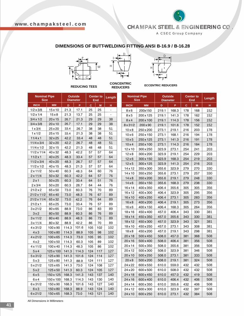
41
DIMENSIONS OF BUTT-WELDING FITTING ANSI B-16.9 / B-16.28
OutsideDiameter
Nominal PipeSize
Center toEnd
Length LengthNominal Pipe
SizeCenter to
EndOutside
Diameter
INCH MM INCH MM
All Dimensions in Millimeters
--
3838515151515164646464767676768989898989898989102102102102102127127127127127140140140140140
152152152152178178178178203203203203330330330330356356356356356381381381381381508508508508508508508508508508508508508
D P C M HD P C M H
CONCENTRICREDUCERSREDUCING TEES ECCENTRIC REDUCERS
w w w . c h a m p a k s t e e l . c o m
A C S E C G r o u p C o m p a n y
CHAMPAK STEEL & ENGINEERING CO .CHAMPAK STEEL & ENGINEERING CO .CHAMPAK STEEL & ENGINEERING CO .CHAMPAK STEEL & ENGINEERING CO .
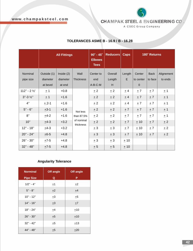
42
TOLERANCES ASME B - 16.9 / B - 16.28
All Fittingso o90 - 45
Elbows
Tees
oReducers Caps 180 Returns
Norminal Outside (1) Inside (2) Wall Center to Overall Length Center Back Alignement
pipe size diameter diameter Thickness end Length E to center to face to ends
at bevel at end A-B-C-M H 0
112’’ - 2 ½’ + 1 +0.8 + 2 + 2 + 4 + 7 + 7 + 1
3’’-3 ½’’ + 1 +1.6 + 2 + 2 + 4 + 7 + 7 + 1
4’’ + 2-1 +1.6 + 2 + 2 + 4 + 7 + 7 + 1
5’’ - 6’’ +3-1 +1.6 + 2 + 2 + 7 + 7 + 7 + 1
8’’ +4-2 +1.6 + 2 + 2 + 7 + 7 + 7 + 1
10’’ +4-3 +3.2 + 2 + 2 + 7 + 10 + 7 + 2
12’’ - 18’’ +4-3 +3.2 + 3 + 3 + 7 + 10 + 7 + 2
20’’ - 24’’ +6-5 +4.8 + 3 + 3 + 7 + 10 + 7 + 2
26’’ - 30’’ +7-5 +4.8 + 3 + 3 + 10
32’’ - 48’’ +7-5 +4.8 + 5 + 5 + 10
Not less
than 87.5%
of nominal
thickness
Angularity Tolerance
Norminal Off angle Off angle
Pipe Size Q P
1I2’’ - 4’’ +1 +2
5’’ - 8’’ +2 +4
10’’ - 12’’ +3 +5
14’’ - 16’’ +3 +7
18’’ - 24’’ +4 +10
26’’ - 30’’ +5 +10
32’’ - 42’’ +5 +13
44’’ - 48’’ +5 +20
w w w . c h a m p a k s t e e l . c o m
A C S E C G r o u p C o m p a n y
CHAMPAK STEEL & ENGINEERING CO .CHAMPAK STEEL & ENGINEERING CO .CHAMPAK STEEL & ENGINEERING CO .CHAMPAK STEEL & ENGINEERING CO .
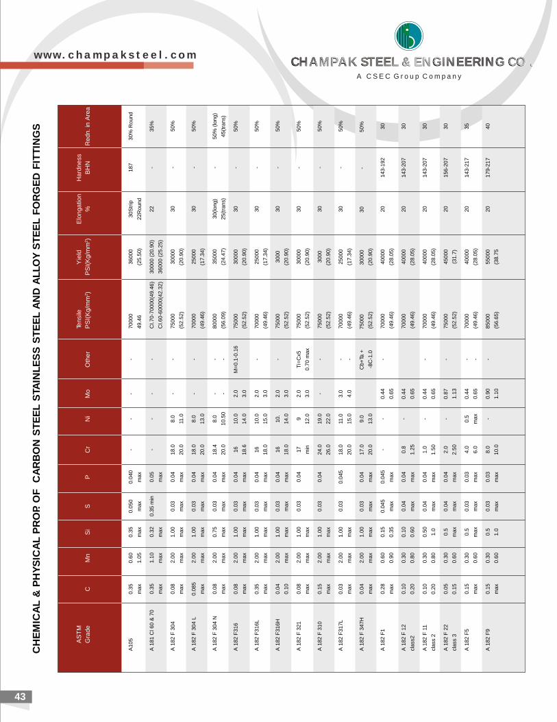
2143
CH
EM
ICA
L &
PH
YS
ICA
L P
RO
P. O
F
CA
RB
ON
ST
EE
L S
TAIN
LE
SS
ST
EE
L A
ND
AL
LO
Y S
TE
EL
FO
RG
ED
FIT
TIN
GS
AS
TM
Tens
ileY
ield
Elo
ngat
ion
Har
dnes
sG
rade
CM
nS
iS
PC
rN
iM
oO
ther
PS
I(K
g/m
m2 )
PS
I(K
g/m
m2 )
%B
HN
Red
n. in
Are
a
A10
50.
350.
600.
350.
050
0.04
0-
--
-70
000
3600
030
Str
ip18
730
% R
ound
max
1.05
max
max
max
49.4
6(2
5.50
)22
Rou
nd
A 1
81 C
l 60
& 7
00.
351.
100.
320.
35 m
in0.
05-
--
-C
I.70-
7000
0(49
.46)
3000
0 (2
0.90
)22
-35
%
max
max
max
max
CI.6
0-60
000(
42.3
2)36
000
(25.
25)
A 1
82 F
304
0.08
2.00
1.00
0.03
0.04
18.0
8.0
--
7500
030
000
30-
50%
max
max
max
max
max
20.0
11.0
(52.
52)
(20.
90)
A 1
82 F
304
L0.
085
2.00
1.00
0.03
0.04
18.0
8.0
--
7000
025
000
30-
50%
max
max
max
max
max
20.0
13.0
(49.
46)
(17.
34)
A 1
82 F
304
N0.
082.
000.
750.
030.
0418
.48.
0-
-80
000
3500
030
(long
)-
50%
(lo
ng)
max
max
max
max
max
20.0
10.5
0-
-(5
6.09
)(2
4.47
)25
(tra
ns)
45(t
rans
)
A 1
82 F
316
0.08
2.00
1.00
0.03
0.04
1610
.02.
0M
=0.1
-0.1
675
000
3000
030
-50
%
max
max
max
max
max
18.6
14.0
3.0
(52.
52)
(20.
90)
A 1
82 F
316L
0.35
2.00
1.00
0.03
0.04
1610
.02.
0-
7000
025
000
30-
50%
max
max
max
max
max
18.0
15.0
3.0
(49.
46)
(17.
34)
A 1
82 F
316H
0.04
2.00
1.00
0.03
0.04
1610
.2.
0-
7500
030
0030
-50
%
0.10
max
max
max
max
18.0
14.0
3.0
(52.
52)
(20.
90)
A 1
82 F
321
0.08
2.00
1.00
0.03
0.04
179
2.0
Ti=
Cx5
7500
030
000
30-
50%
max
max
max
min
12.0
3.0
0.70
max
(52.
52)
(20.
90)
A 1
82 F
310
0.15
2.00
1.00
0.03
0.04
24.0
19.0
--
7500
030
0030
-50
%
max
max
max
26.0
22.0
(52.
52)
(20.
90)
A 1
82 F
317L
0.03
2.00
1.00
0.03
0.04
518
.011
.03.
0-
7000
025
000
30-
50%
max
max
max
20.0
15.0
4.0
-(4
9.46
)(1
7.34
)
A 1
82 F
347
H0.
042.
001.
000.
030.
0417
.09.
0C
b+Ta
+75
000
3000
030
-50
%
max
max
max
max
max
20.0
13.0
-8C
-1.0
(52.
52)
(20.
90)
A 1
82 F
10.
280.
600.
150.
045
0.04
5-
-0.
44-
7000
040
000
2014
3-19
230
max
0.90
0.35
max
max
0.65
(49.
46)
(28.
05)
A 1
82 F
12
0.10
0.30
0.10
0.04
0.04
0.8
-0.
4470
000
4000
020
143-
207
30
clas
s20.
200.
800.
60m
axm
ax1.
250.
65(4
9.46
)(2
8.05
)
A 1
82 F
11
0.10
0.30
0.50
0.04
0.04
1.0
-0.
44-
7000
040
000
2014
3-20
730
clas
s 2
0.20
0.80
1.0
max
max
1.50
0.65
(49.
46)
(28.
05)
A 1
82 F
22
0.05
0.30
0.5
0.04
0.04
2.0
-0.
87-
7500
045
000
2015
6-20
730
clas
s 3
0.15
0.60
max
max
max
2.50
1.13
(52.
52)
(31.
7)
A 1
82 F
50.
150.
300.
50.
030.
034.
00.
50.
44-
7000
040
000
2014
3-21
735
max
0.60
max
max
max
6.0
max
0.65
-(4
9.46
)(2
8.05
)
A 1
82 F
90.
150.
300.
50.
030.
038.
0-
0.90
-85
000
5500
020
179-
217
40
max
0.60
1.0
max
max
10.0
1.10
(56.
65)
(38.
75
w w w . c h a m p a k s t e e l . c o m
A C S E C G r o u p C o m p a n y
CHAMPAK STEEL & ENGINEERING CO .CHAMPAK STEEL & ENGINEERING CO .CHAMPAK STEEL & ENGINEERING CO .CHAMPAK STEEL & ENGINEERING CO .
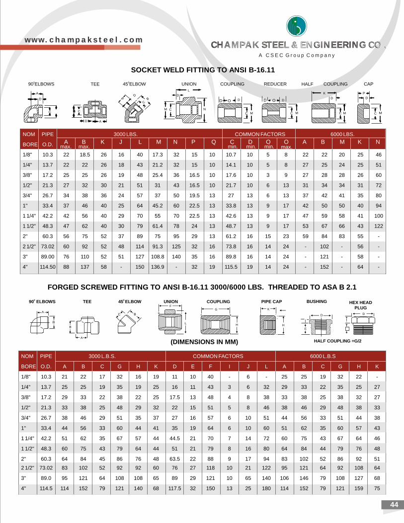
44
SOCKET WELD FITTING TO ANSI B-16.11
MC C MC
D
K PD
C M
A
090 ELBOWS HALF COUPLING CAP
AD
CB
DB
C
M C
D
L
N
DOD D O D
M
TEE 045 ELBOW UNION COUPLING REDUCER
FORGED SCREWED FITTING TO ANSI B-16.11 3000/6000 LBS. THREADED TO ASA B 2.1
BUSHING
DD
E
HEX HEAD PLUG
PIPE CAP
K
H
A
B
AG
H
F
L
COUPLINGUNION0 45 ELBOWTEE090 ELBOWS
HALF COUPLING =G/2(DIMENSIONS IN MM)
A B K Jmax. max.
L M N P Q Cmin.min. min. max.D O O A B M K N
NOM PIPE 3000 LBS. COMMON FACTORS 6000 LBS.
BORE O.D.
1/8" 10.3 22 18.5 26 16 40 17.3 32 15 10 10.7 10 5 8 22 22 20 25 46
1/4" 13.7 22 22 26 18 43 21.2 32 15 10 14.1 10 5 8 27 25 24 25 51
3/8" 17.2 25 25 26 19 48 25.4 36 16.5 10 17.6 10 3 9 27 28 28 26 60
1/2" 21.3 27 32 30 21 51 31 43 16.5 10 21.7 10 6 13 31 34 34 31 72
3/4" 26.7 34 38 36 24 57 37 50 19.5 13 27 13 6 13 37 42 41 35 80
1" 33.4 37 46 40 25 64 45.2 60 22.5 13 33.8 13 9 17 42 50 50 40 94
1 1/4" 42.2 42 56 40 29 70 55 70 22.5 13 42.6 13 9 17 47 59 58 41 100
1 1/2" 48.3 47 62 40 30 79 61.4 78 24 13 48.7 13 9 17 53 67 66 43 122
2" 60.3 56 75 52 37 89 75 95 29 13 61.2 16 15 23 59 84 83 55 -
2 1/2" 73.02 60 92 52 48 114 91.3 125 32 16 73.8 16 14 24 - 102 - 56 -
3" 89.00 76 110 52 51 127 108.8 140 35 16 89.8 16 14 24 - 121 - 58 -
4" 114.50 88 137 58 - 150 136.9 - 32 19 115.5 19 14 24 - 152 - 64 -
NOM PIPE 3000 L.B.S. COMMON FACTORS 6000 L.B.S
BORE O.D. A B C G H K D E F I J L A B C G H K
1/8" 10.3 21 22 17 32 16 19 11 10 40 - 6 - 25 25 19 32 22 -
1/4" 13.7 25 25 19 35 19 25 16 11 43 3 6 32 29 33 22 35 25 27
3/8" 17.2 29 33 22 38 22 25 17.5 13 48 4 8 38 33 38 25 38 32 27
1/2" 21.3 33 38 25 48 29 32 22 15 51 5 8 46 38 46 29 48 38 33
3/4" 26.7 38 46 29 51 35 37 27 16 57 6 10 51 44 56 33 51 44 38
1" 33.4 44 56 33 60 44 41 35 19 64 6 10 60 51 62 35 60 57 43
1 1/4" 42.2 51 62 35 67 57 44 44.5 21 70 7 14 72 60 75 43 67 64 46
1 1/2" 48.3 60 75 43 79 64 44 51 21 79 8 16 80 64 84 44 79 76 48
2" 60.3 64 84 45 86 76 48 63.5 22 88 9 17 94 83 102 52 86 92 51
2 1/2" 73.02 83 102 52 92 92 60 76 27 118 10 21 122 95 121 64 92 108 64
3" 89.0 95 121 64 108 108 65 89 29 121 10 65 140 106 146 79 108 127 68
4" 114.5 114 152 79 121 140 68 117.5 32 150 13 25 180 114 152 79 121 159 75
w w w . c h a m p a k s t e e l . c o m
A C S E C G r o u p C o m p a n y
CHAMPAK STEEL & ENGINEERING CO .CHAMPAK STEEL & ENGINEERING CO .CHAMPAK STEEL & ENGINEERING CO .CHAMPAK STEEL & ENGINEERING CO .
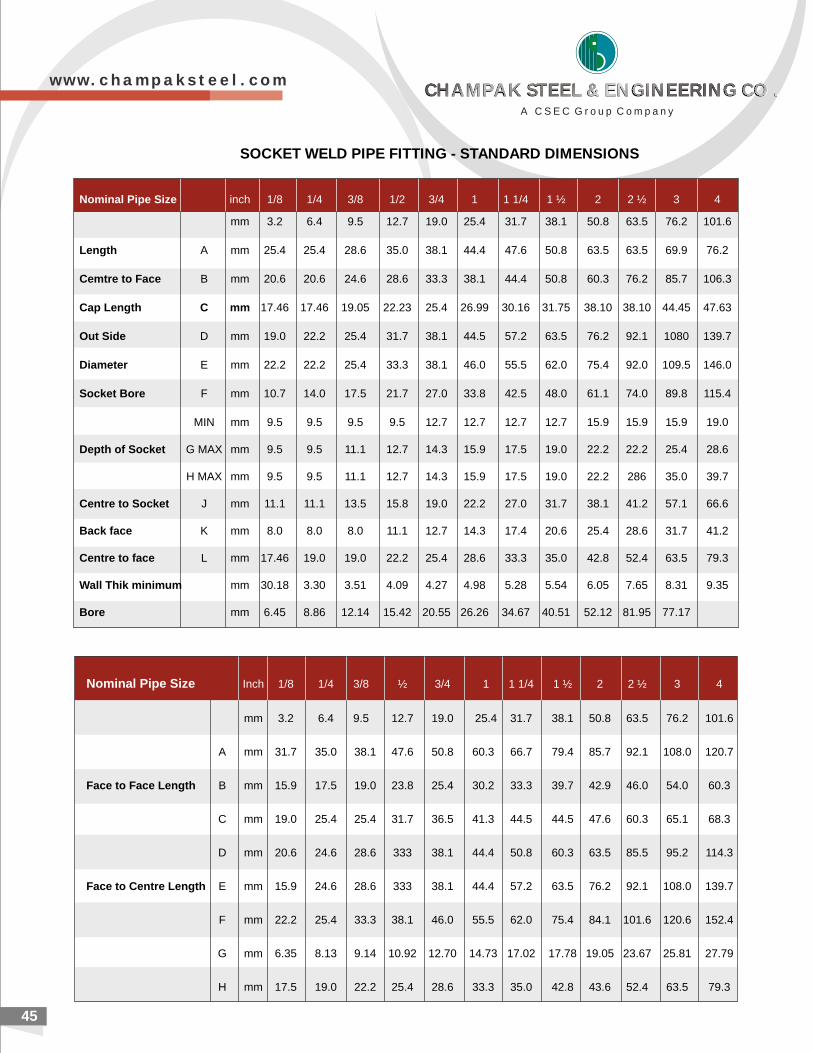
2145
SOCKET WELD PIPE FITTING - STANDARD DIMENSIONS
Nominal Pipe Size inch 1/8 1/4 3/8 1/2 3/4 1 1 1/4 1 ½ 2 2 ½ 3 4
mm 3.2 6.4 9.5 12.7 19.0 25.4 31.7 38.1 50.8 63.5 76.2 101.6
Length A mm 25.4 25.4 28.6 35.0 38.1 44.4 47.6 50.8 63.5 63.5 69.9 76.2
Cemtre to Face B mm 20.6 20.6 24.6 28.6 33.3 38.1 44.4 50.8 60.3 76.2 85.7 106.3
Cap Length C mm 17.46 17.46 19.05 22.23 25.4 26.99 30.16 31.75 38.10 38.10 44.45 47.63
Out Side D mm 19.0 22.2 25.4 31.7 38.1 44.5 57.2 63.5 76.2 92.1 1080 139.7
Diameter E mm 22.2 22.2 25.4 33.3 38.1 46.0 55.5 62.0 75.4 92.0 109.5 146.0
Socket Bore F mm 10.7 14.0 17.5 21.7 27.0 33.8 42.5 48.0 61.1 74.0 89.8 115.4
MIN mm 9.5 9.5 9.5 9.5 12.7 12.7 12.7 12.7 15.9 15.9 15.9 19.0
Depth of Socket G MAX mm 9.5 9.5 11.1 12.7 14.3 15.9 17.5 19.0 22.2 22.2 25.4 28.6
H MAX mm 9.5 9.5 11.1 12.7 14.3 15.9 17.5 19.0 22.2 286 35.0 39.7
Centre to Socket J mm 11.1 11.1 13.5 15.8 19.0 22.2 27.0 31.7 38.1 41.2 57.1 66.6
Back face K mm 8.0 8.0 8.0 11.1 12.7 14.3 17.4 20.6 25.4 28.6 31.7 41.2
Centre to face L mm 17.46 19.0 19.0 22.2 25.4 28.6 33.3 35.0 42.8 52.4 63.5 79.3
Wall Thik minimum mm 30.18 3.30 3.51 4.09 4.27 4.98 5.28 5.54 6.05 7.65 8.31 9.35
Bore mm 6.45 8.86 12.14 15.42 20.55 26.26 34.67 40.51 52.12 81.95 77.17
Nominal Pipe Size Inch 1/8 1/4 3/8 ½ 3/4 1 1 1/4 1 ½ 2 2 ½ 3 4
mm 3.2 6.4 9.5 12.7 19.0 25.4 31.7 38.1 50.8 63.5 76.2 101.6
A mm 31.7 35.0 38.1 47.6 50.8 60.3 66.7 79.4 85.7 92.1 108.0 120.7
Face to Face Length B mm 15.9 17.5 19.0 23.8 25.4 30.2 33.3 39.7 42.9 46.0 54.0 60.3
C mm 19.0 25.4 25.4 31.7 36.5 41.3 44.5 44.5 47.6 60.3 65.1 68.3
D mm 20.6 24.6 28.6 333 38.1 44.4 50.8 60.3 63.5 85.5 95.2 114.3
Face to Centre Length E mm 15.9 24.6 28.6 333 38.1 44.4 57.2 63.5 76.2 92.1 108.0 139.7
F mm 22.2 25.4 33.3 38.1 46.0 55.5 62.0 75.4 84.1 101.6 120.6 152.4
G mm 6.35 8.13 9.14 10.92 12.70 14.73 17.02 17.78 19.05 23.67 25.81 27.79
H mm 17.5 19.0 22.2 25.4 28.6 33.3 35.0 42.8 43.6 52.4 63.5 79.3
w w w . c h a m p a k s t e e l . c o m
A C S E C G r o u p C o m p a n y
CHAMPAK STEEL & ENGINEERING CO .CHAMPAK STEEL & ENGINEERING CO .CHAMPAK STEEL & ENGINEERING CO .CHAMPAK STEEL & ENGINEERING CO .
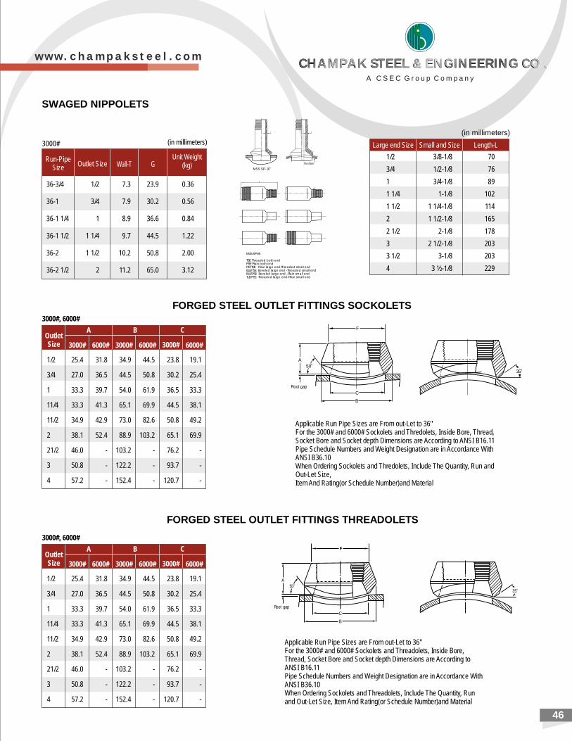
2046
SWAGED NIPPOLETS
Applicable Run Pipe Sizes are From out-Let to 36"For the 3000# and 6000# Sockolets and Threadolets, Inside Bore, Thread, Socket Bore and Socket depth Dimensions are According to ANSI B16.11Pipe Schedule Numbers and Weight Designation are in Accordance With ANSI B36.10When Ordering Sockolets and Threadolets, Include The Quantity, Run and Out-Let Size, Item And Rating(or Schedule Number)and Material
FORGED STEEL OUTLET FITTINGS THREADOLETS
FORGED STEEL OUTLET FITTINGS SOCKOLETS
Applicable Run Pipe Sizes are From out-Let to 36"For the 3000# and 6000# Sockolets and Thredolets, Inside Bore, Thread, Socket Bore and Socket depth Dimensions are According to ANSI B16.11Pipe Schedule Numbers and Weight Designation are in Accordance With ANSI B36.10When Ordering Sockolets and Thredolets, Include The Quantity, Run and Out-Let Size, Item And Rating(or Schedule Number)and Material
36-3/4 1/2 7.3 23.9 0.36
36-1 3/4 7.9 30.2 0.56
36-1 1/4 1 8.9 36.6 0.84
36-1 1/2 1 1/4 9.7 44.5 1.22
36-2 1 1/2 10.2 50.8 2.00
36-2 1/2 2 11.2 65.0 3.12
Run-PipeSize
Unit Weight(kg)Outlet Size Wall-T G
3000# (in millimeters)
1/2 3/8-1/8 70
3/4 1/2-1/8 76
1 3/4-1/8 89
1 1/4 1-1/8 102
1 1/2 1 1/4-1/8 114
2 1 1/2-1/8 165
2 1/2 2-1/8 178
3 2 1/2-1/8 203
3 1/2 3-1/8 203
4 3 ½-1/8 229
Large end Size Small and Size Length-L
(in millimeters)
MSS SP-95
TBE Threaded both endPBE Plain both endPlE/TSE Plain large end-Threaded small endBLE/TSE Beveled large end -Threaded small endBLE/PSE Beveled large end -Plain small endTLE/PSE Threaded large end-Plain small end
MSS SP- 97
Run-Pipe
T
G
T
G
L
F
A0
50
C
B
Root gap
035
F
C
B
A
Root gap
o50
o35
3000#, 6000#
1/2 25.4 31.8 34.9 44.5 23.8 19.1
3/4 27.0 36.5 44.5 50.8 30.2 25.4
1 33.3 39.7 54.0 61.9 36.5 33.3
11/4 33.3 41.3 65.1 69.9 44.5 38.1
11/2 34.9 42.9 73.0 82.6 50.8 49.2
2 38.1 52.4 88.9 103.2 65.1 69.9
21/2 46.0 - 103.2 - 76.2 -
3 50.8 - 122.2 - 93.7 -
4 57.2 - 152.4 - 120.7 -
A B COutletSize 6000#3000#6000#3000#3000# 6000#
w w w . c h a m p a k s t e e l . c o m
A C S E C G r o u p C o m p a n y
CHAMPAK STEEL & ENGINEERING CO .CHAMPAK STEEL & ENGINEERING CO .CHAMPAK STEEL & ENGINEERING CO .CHAMPAK STEEL & ENGINEERING CO .
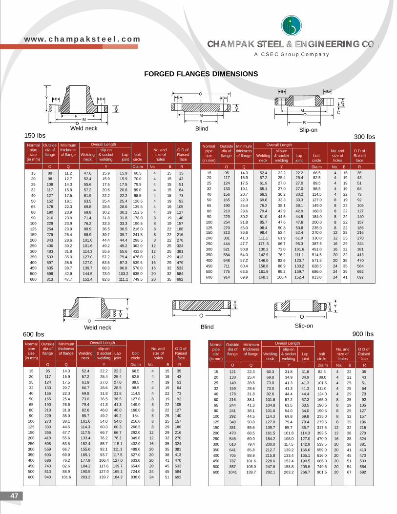
2147
150 lbs 300 lbs
Weld neck Blind Slip-on
Normal Outside Minimumpipe dia of thickness slip-on No. and O D ofsize flange of flange Welding & socket Lap bolt size of Raised
(in mm) neck welding joint circle holes face
O Q Y Dia.m No. B R
15 121 22.3 60.3 31.8 31.8 82.5 4 22 3520 130 25.4 69.8 34.9 34.9 89.0 4 22 4325 149 28.6 73.0 41.3 41.3 101.5 4 25 5132 159 28.6 73.0 41.3 41.3 111.0 4 25 6440 178 31.8 82.6 44.4 44.4 124.0 4 29 7350 216 38.1 101.6 57.2 57.2 165.0 8 25 9265 244 41.3 104.8 63.5 63.5 190.5 8 29 10580 241 38.1 101.6 54.0 54.0 190.5 8 25 127100 292 44.5 114.3 69.8 69.8 235.0 8 32 157125 349 50.8 127.0 79.4 79.4 279.5 8 35 186150 381 55.6 139.7 85.7 85.7 317.5 12 32 216200 470 68.5 161.5 101.8 114.3 393.5 12 38 270250 546 69.9 184.2 108.0 127.0 470.0 16 38 324300 610 79.4 200.0 117.5 142.9 533.5 20 38 381350 641 85.8 212.7 130.2 155.6 559.0 20 41 413400 705 88.9 215.8 133.4 165.1 616.0 20 45 470450 787 101.6 228.6 152.4 190.5 686.0 20 51 533500 857 108.0 247.6 158.8 209.6 749.5 20 54 584600 1041 139.7 292.1 203.2 266.7 901.5 20 67 692
Overall Length
900 lbs
Normal Outside Minimumpipe dia of thickness slip-on No. and O D ofsize flange of flange Welding & socket Lap bolt size of Raised
(in mm) neck welding joint circle holes face
O Q Y Dia.m No. B R
15 95 14.3 52.4 22.2 22.2 66.5 4 15 3520 117 15.9 57.2 25.4 25.4 82.5 4 19 4325 124 17.5 61.9 27.0 27.0 89.5 4 19 5132 133 20.7 66.7 28.6 28.5 98.5 4 19 6440 156 22.3 69.8 31.8 31.8 114.5 4 22 7350 165 25.4 73.0 36.5 36.5 127.0 8 19 9265 190 28.6 79.4 41.3 41.3 149.0 8 22 10580 210 31.8 82.6 46.0 46.0 168.0 8 22 12790 229 35.0 85.7 49.2 49.2 184 8 25 140
100 273 38.1 101.6 54.0 54.0 216.0 8 25 157125 330 44.5 114.3 60.3 60.3 266.5 8 29 186150 356 47.7 117.5 66.7 66.7 292.0 12 29 216200 419 55.6 133.4 76.2 76.2 349.0 12 32 270250 508 63.5 152.4 85.7 115.1 432.0 16 35 324300 559 66.7 155.6 92.1 111.1 489.0 20 35 381350 603 69.9 165.1 93.7 117.5 527.0 20 38 413400 686 76.2 177.8 106.4 127.0 603.0 20 41 470450 743 82.6 184.2 117.6 139.7 654.0 20 45 533500 813 88.9 190.5 127.0 165.1 724.0 24 45 584600 940 101.6 203.2 139.7 184.2 838.0 24 51 692
Overall Length
600 lbsWeld neck Blind Slip-on
FORGED FLANGES DIMENSIONS
Normal Outside Minimumpipe dia of thickness slip-on No. and O D ofsize flange of flange Welding & socket Lap bolt size of Raised
(in mm) neck welding joint circle holes face
O Q Y Dia.m No. B R
15 89 11.2 47.6 15.9 15.9 60.5 4 15 3520 98 12.7 52.4 15.9 15.9 70.0 4 15 4325 108 14.3 55.6 17.5 17.5 79.5 4 15 5132 117 15.9 57.2 20.6 20.6 89.0 4 15 6440 127 17.5 61.9 22.2 22.2 98.5 4 15 7350 152 19.1 63.5 25.4 25.4 120.5 4 19 9265 178 22.3 69.8 28.6 28.6 139.5 4 19 10580 190 23.9 69.8 30.2 30.2 152.5 4 19 12790 216 23.9 71.4 31.8 31.8 178.0 8 19 140
100 229 23.9 76.2 33.3 33.3 190.5 8 19 157125 254 23.9 88.9 36.5 36.5 216.0 8 22 186150 279 25.4 88.9 39.7 39.7 241.5 8 22 216200 343 28.6 101.6 44.4 44.4 298.5 8 22 270250 406 30.2 101.6 49.2 49.2 362.0 12 25 324300 483 31.8 114.3 55.6 55.6 432.0 12 25 381350 533 35.0 127.0 57.2 79.4 476.0 12 29 413400 597 36.6 127.0 63.5 87.3 539.5 16 29 470450 635 39.7 139.7 68.3 96.8 578.0 16 32 533500 698 42.9 144.5 73.0 103.2 635.0 20 32 584600 813 47.7 152.4 82.6 111.1 749.5 20 35 692
Overall Length Normal Outside Minimumpipe dia of thickness slip-on No. and O D ofsize flange of flange Welding & socket Lap bolt size of Raised
(in mm) neck welding joint circle holes face
O Q Y Dia.m No. B R
Overall Length
15 95 14.3 52.4 22.2 22.2 66.5 4 15 3520 117 15.9 57.2 25.4 25.4 82.5 4 19 4325 124 17.5 61.9 27.0 27.0 89.5 4 19 5132 133 19.1 65.1 27.0 27.0 98.5 4 19 6440 156 20.7 68.3 30.2 30.2 114.5 4 22 7350 165 22.3 69.8 33.3 33.3 127.0 8 19 9265 190 25.4 76.2 38.1 38.1 149.0 8 22 10580 210 28.6 79.4 42.9 42.9 168.0 8 22 12790 229 30.2 81.0 44.5 44.5 184.0 8 22 140100 254 31.8 85.7 47.6 47.6 200.0 8 22 157125 279 35.0 98.4 50.8 50.8 235.0 8 22 186150 313 36.6 98.4 52.4 52.4 270.0 12 22 216200 381 41.3 111.1 61.9 61.9 330.0 12 25 270250 444 47.7 117..5 66.7 95.3 387.5 16 29 324300 521 50.8 130.2 73.0 101.6 451.0 16 32 381350 584 54.0 142.9 76.2 111.1 514.5 20 32 413400 648 57.2 146.0 82.6 120.7 571.5 20 35 470450 711 60.4 158.8 88.9 130.2 628.5 24 35 584500 775 63.5 161.9 95.2 139.7 686.0 24 35 692600 914 69.9 168.3 106.4 152.4 813.0 24 41 692
w w w . c h a m p a k s t e e l . c o m
A C S E C G r o u p C o m p a n y
CHAMPAK STEEL & ENGINEERING CO .CHAMPAK STEEL & ENGINEERING CO .CHAMPAK STEEL & ENGINEERING CO .CHAMPAK STEEL & ENGINEERING CO .
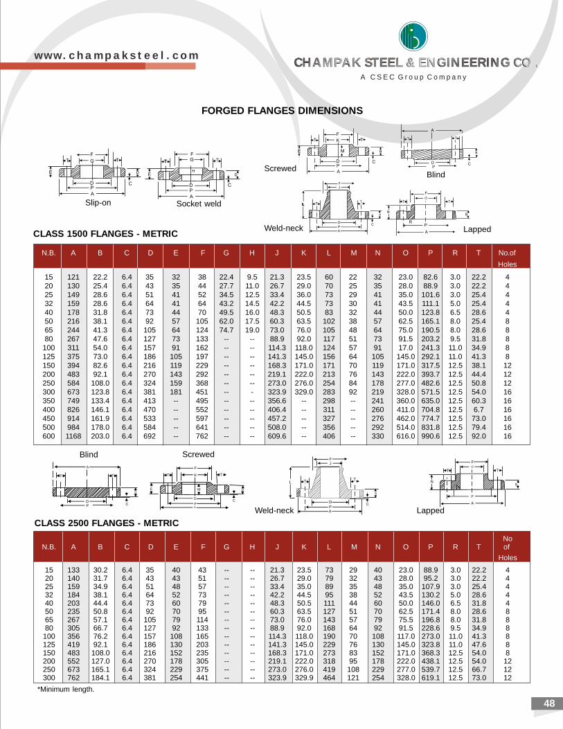
2048
Slip-on Socket weld
Weld-neck Lapped
ScrewedBlind
N.B. A B C D E F G H J K L M N O P R T No.of
Holes
15 121 22.2 6.4 35 32 38 22.4 9.5 21.3 23.5 60 22 32 23.0 82.6 3.0 22.2 420 130 25.4 6.4 43 35 44 27.7 11.0 26.7 29.0 70 25 35 28.0 88.9 3.0 22.2 425 149 28.6 6.4 51 41 52 34.5 12.5 33.4 36.0 73 29 41 35.0 101.6 3.0 25.4 432 159 28.6 6.4 64 41 64 43.2 14.5 42.2 44.5 73 30 41 43.5 111.1 5.0 25.4 440 178 31.8 6.4 73 44 70 49.5 16.0 48.3 50.5 83 32 44 50.0 123.8 6.5 28.6 450 216 38.1 6.4 92 57 105 62.0 17.5 60.3 63.5 102 38 57 62.5 165.1 8.0 25.4 865 244 41.3 6.4 105 64 124 74.7 19.0 73.0 76.0 105 48 64 75.0 190.5 8.0 28.6 880 267 47.6 6.4 127 73 133 -- -- 88.9 92.0 117 51 73 91.5 203.2 9.5 31.8 8
100 311 54.0 6.4 157 91 162 -- -- 114.3 118.0 124 57 91 17.0 241.3 11.0 34.9 8125 375 73.0 6.4 186 105 197 -- -- 141.3 145.0 156 64 105 145.0 292.1 11.0 41.3 8150 394 82.6 6.4 216 119 229 -- -- 168.3 171.0 171 70 119 171.0 317.5 12.5 38.1 12200 483 92.1 6.4 270 143 292 -- -- 219.1 222.0 213 76 143 222.0 393.7 12.5 44.4 12250 584 108.0 6.4 324 159 368 -- -- 273.0 276.0 254 84 178 277.0 482.6 12.5 50.8 12300 673 123.8 6.4 381 181 451 -- - 323.9 329.0 283 92 219 328.0 571.5 12.5 54.0 16350 749 133.4 6.4 413 -- 495 -- -- 356.6 -- 298 -- 241 360.0 635.0 12.5 60.3 16400 826 146.1 6.4 470 -- 552 -- -- 406.4 -- 311 -- 260 411.0 704.8 12.5 6.7 16450 914 161.9 6.4 533 -- 597 -- -- 457.2 -- 327 -- 276 462.0 774.7 12.5 73.0 16500 984 178.0 6.4 584 -- 641 -- -- 508.0 -- 356 -- 292 514.0 831.8 12.5 79.4 16600 1168 203.0 6.4 692 -- 762 -- -- 609.6 -- 406 -- 330 616.0 990.6 12.5 92.0 16
CLASS 1500 FLANGES - METRIC
FORGED FLANGES DIMENSIONS
Weld-neck Lapped
ScrewedBlind
CLASS 2500 FLANGES - METRIC
NoN.B. A B C D E F G H J K L M N O P R T of
Holes
15 133 30.2 6.4 35 40 43 -- -- 21.3 23.5 73 29 40 23.0 88.9 3.0 22.2 420 140 31.7 6.4 43 43 51 -- -- 26.7 29.0 79 32 43 28.0 95.2 3.0 22.2 425 159 34.9 6.4 51 48 57 -- -- 33.4 35.0 89 35 48 35.0 107.9 3.0 25.4 432 184 38.1 6.4 64 52 73 -- -- 42.2 44.5 95 38 52 43.5 130.2 5.0 28.6 440 203 44.4 6.4 73 60 79 -- -- 48.3 50.5 111 44 60 50.0 146.0 6.5 31.8 450 235 50.8 6.4 92 70 95 -- -- 60.3 63.5 127 51 70 62.5 171.4 8.0 28.6 865 267 57.1 6.4 105 79 114 -- -- 73.0 76.0 143 57 79 75.5 196.8 8.0 31.8 880 305 66.7 6.4 127 92 133 -- -- 88.9 92.0 168 64 92 91.5 228.6 9.5 34.9 8
100 356 76.2 6.4 157 108 165 -- -- 114.3 118.0 190 70 108 117.0 273.0 11.0 41.3 8125 419 92.1 6.4 186 130 203 -- -- 141.3 145.0 229 76 130 145.0 323.8 11.0 47.6 8150 483 108.0 6.4 216 152 235 -- -- 168.3 171.0 273 83 152 171.0 368.3 12.5 54.0 8200 552 127.0 6.4 270 178 305 -- -- 219.1 222.0 318 95 178 222.0 438.1 12.5 54.0 12250 673 165.1 6.4 324 229 375 -- -- 273.0 276.0 419 108 229 277.0 539.7 12.5 66.7 12300 762 184.1 6.4 381 254 441 -- -- 323.9 329.9 464 121 254 328.0 619.1 12.5 73.0 12
*Minimum length.
w w w . c h a m p a k s t e e l . c o m
A C S E C G r o u p C o m p a n y
CHAMPAK STEEL & ENGINEERING CO .CHAMPAK STEEL & ENGINEERING CO .CHAMPAK STEEL & ENGINEERING CO .CHAMPAK STEEL & ENGINEERING CO .
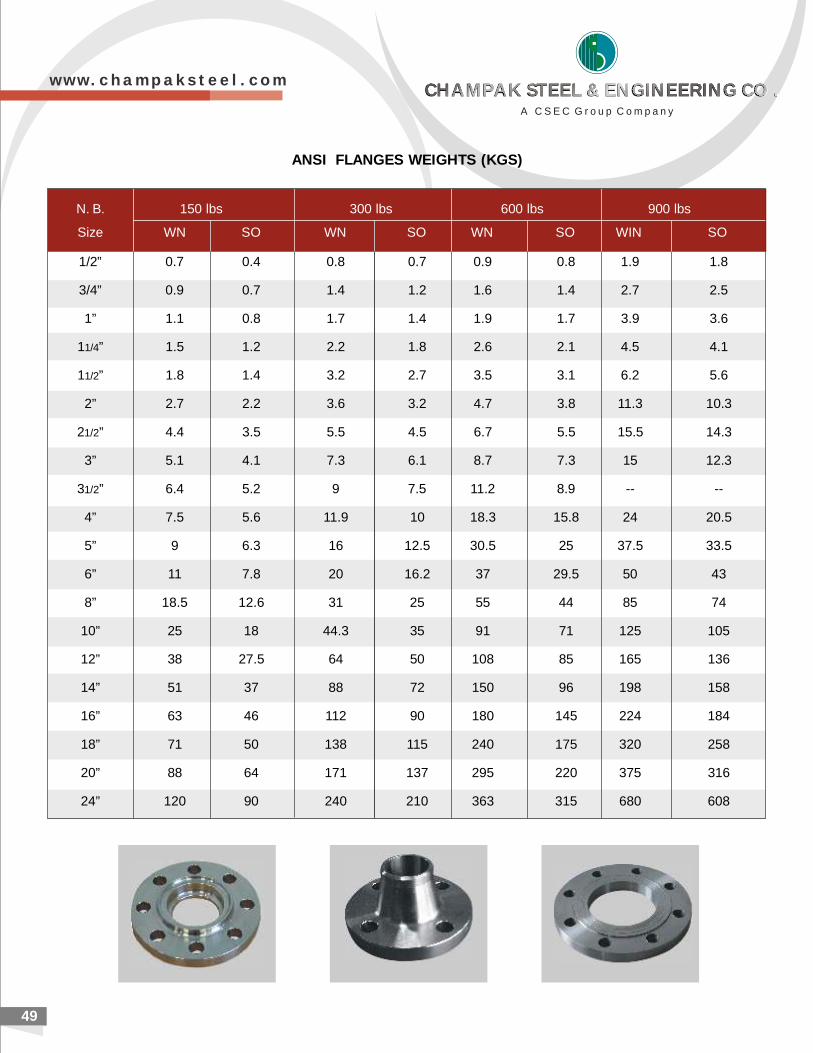
2149
N. B. 150 lbs 300 lbs 600 lbs 900 lbs
Size WN SO WN SO WN SO WIN SO
1/2” 0.7 0.4 0.8 0.7 0.9 0.8 1.9 1.8
3/4” 0.9 0.7 1.4 1.2 1.6 1.4 2.7 2.5
1” 1.1 0.8 1.7 1.4 1.9 1.7 3.9 3.6
11/4” 1.5 1.2 2.2 1.8 2.6 2.1 4.5 4.1
11/2” 1.8 1.4 3.2 2.7 3.5 3.1 6.2 5.6
2” 2.7 2.2 3.6 3.2 4.7 3.8 11.3 10.3
21/2” 4.4 3.5 5.5 4.5 6.7 5.5 15.5 14.3
3” 5.1 4.1 7.3 6.1 8.7 7.3 15 12.3
31/2” 6.4 5.2 9 7.5 11.2 8.9 -- --
4” 7.5 5.6 11.9 10 18.3 15.8 24 20.5
5” 9 6.3 16 12.5 30.5 25 37.5 33.5
6” 11 7.8 20 16.2 37 29.5 50 43
8” 18.5 12.6 31 25 55 44 85 74
10” 25 18 44.3 35 91 71 125 105
12” 38 27.5 64 50 108 85 165 136
14” 51 37 88 72 150 96 198 158
16” 63 46 112 90 180 145 224 184
18” 71 50 138 115 240 175 320 258
20” 88 64 171 137 295 220 375 316
24” 120 90 240 210 363 315 680 608
ANSI FLANGES WEIGHTS (KGS)
w w w . c h a m p a k s t e e l . c o m
A C S E C G r o u p C o m p a n y
CHAMPAK STEEL & ENGINEERING CO .CHAMPAK STEEL & ENGINEERING CO .CHAMPAK STEEL & ENGINEERING CO .CHAMPAK STEEL & ENGINEERING CO .
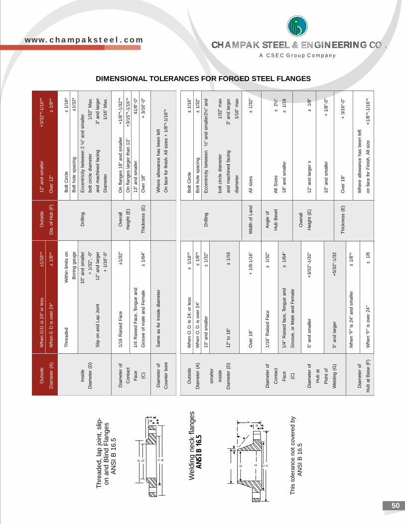
2050
DIMENSIONAL TOLERANCES FOR FORGED STEEL FLANGES
Thre
aded,
lap
join
t, s
lip-
on
and
Blin
d F
langes
AN
SI
B 1
6.5
This
tole
rance
not
cove
red
by
AN
SI
B 1
6.5
Out
side
Whe
n O
. D. i
s 24
: or
less
± 1/
16”*
Bol
t C
ircle
± 1
/16”
Dia
met
er (
A)
Whe
n O
. D. i
s ov
er 2
4”±
1/8
”*B
olt
hole
spa
cing
± 1
/32”
10”
and
smal
ler
± 1
/32”
Dril
ling
Ecc
entr
icity
bet
wee
n½
” an
d sm
alle
r2½
” an
dsm
alle
r
insi
debo
lt ci
rcle
dia
met
er1/
32”
max
Dia
met
er (
D)
12”
to 1
8”±
1/1
6an
d m
achi
ned
faci
ng3”
and
larg
er
diam
eter
1/16
” m
ax
Ove
r 18
”+
1/8
-1/1
6”W
idth
of
Land
All
size
s±
1/3
2”
Dia
met
er o
f1/
16”
Rai
sed
Face
± 1
/32”
Ang
le o
f
Con
tact
Hub
Bev
elA
ll S
izes
± 2
½”
Face
1/4”
Rai
sed
face
, Ton
gue
and
± 1/
64”
18”
and
smal
ler
± 1
/16
(C)
Gro
ove,
or
Mal
e an
d Fe
mal
e
Ove
rall
Dia
met
er o
f5”
and
sm
alle
r+
3/32
”-1/
32”
Hei
ght
(E)
12”
and
larg
er ±
± 1
/8”
Hub
at
Poi
nt o
f10
” an
d sm
alle
r+
1/8
”-0”
Wel
ding
(G
)5”
and
larg
er+
5/32
”-1/
32
Thi
ckne
ss (
E)
Ove
r 18
”+
3/1
6”-0
”
Whe
n “F
” is
24”
and
sm
alle
r±
1/8
”*
Dia
met
er o
fW
here
allo
wan
ce h
as b
een
left
Hub
at
Bas
e (F
)W
hen
“F”
is o
ver
24”
± 1
/8on
face
for
Fin
ish,
All
size
+1/
8”*-
1/16
”*
Out
side
Whe
n O
.D. i
s 24
” or
less
±1/
16**
Out
side
12”
and
smal
ler
+3/
32”*
-1/1
6**
Dia
met
er (
A)
Whe
n 0.
D is
ove
r 24
”±
1/8
**D
ia. o
f H
ub (
F)
Ove
r 12
”±
1/8
**
Thr
eade
dW
ithin
lim
its o
nB
olt
Circ
le±
1/16
*
Bor
ing
gaug
eB
olt
hole
spa
cing
±1/3
2*
Insi
de10
” an
d sm
alle
rD
rillin
gE
ccen
tric
ity b
etw
een
2 ½
” an
d sm
alle
r
Dia
met
er (
D)
+ 1
/32”
, -0
”bo
lt ci
rcle
dia
met
er1/
32”
Max
.
Slip
on
and
Lap
Join
t12
” an
d la
rger
and
mac
hine
d fa
cing
3” a
nd la
rger
+ 1
/16”
-0”
Dia
met
er1/
16”
Max
.
Dia
met
er o
f1/
16 R
aise
d Fa
ce±1
/32”
Ove
rall
On
flang
es 1
8” a
nd s
mal
ler
+1/
8”*-
1/32
”*
Con
tact
Hei
ght
(E)
On
flang
es la
rger
tha
n 13
”+
3/15
”*-1
/16”
*
Face
1/4
Rai
sed
Face
, Ton
gue
and
13”
and
smal
ler
41/8
”-0”
(C)
Gro
ove
of m
ale
and
Fem
ale
± 1
/64”
Thi
ckne
ss (
E)
Ove
r 18
”+
3/1
6”-0
”
Dia
met
er o
fS
ame
as fo
r in
side
dia
met
erW
here
allo
wan
ce h
as b
een
left
Cou
nter
bor
eO
n fa
ce fo
r fin
ish:
All
size
s +
1/8
”*-1
/16”
*
Weld
ing
neck
fla
nges
AN
SI B
16.
5
w w w . c h a m p a k s t e e l . c o m
A C S E C G r o u p C o m p a n y
CHAMPAK STEEL & ENGINEERING CO .CHAMPAK STEEL & ENGINEERING CO .CHAMPAK STEEL & ENGINEERING CO .CHAMPAK STEEL & ENGINEERING CO .
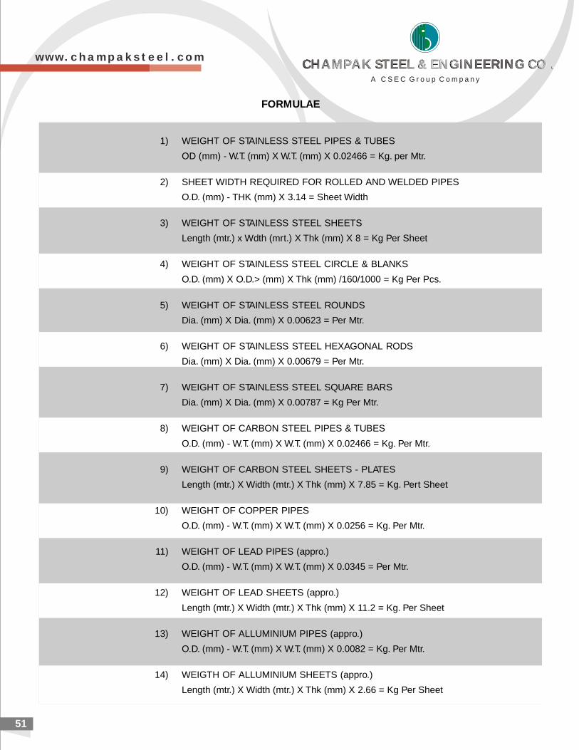
51
FORMULAE
1) WEIGHT OF STAINLESS STEEL PIPES & TUBES
OD (mm) - W.T. (mm) X W.T. (mm) X 0.02466 = Kg. per Mtr.
2) SHEET WIDTH REQUIRED FOR ROLLED AND WELDED PIPES
O.D. (mm) - THK (mm) X 3.14 = Sheet Width
3) WEIGHT OF STAINLESS STEEL SHEETS
Length (mtr.) x Wdth (mrt.) X Thk (mm) X 8 = Kg Per Sheet
4) WEIGHT OF STAINLESS STEEL CIRCLE & BLANKS
O.D. (mm) X O.D.> (mm) X Thk (mm) /160/1000 = Kg Per Pcs.
5) WEIGHT OF STAINLESS STEEL ROUNDS
Dia. (mm) X Dia. (mm) X 0.00623 = Per Mtr.
6) WEIGHT OF STAINLESS STEEL HEXAGONAL RODS
Dia. (mm) X Dia. (mm) X 0.00679 = Per Mtr.
7) WEIGHT OF STAINLESS STEEL SQUARE BARS
Dia. (mm) X Dia. (mm) X 0.00787 = Kg Per Mtr.
8) WEIGHT OF CARBON STEEL PIPES & TUBES
O.D. (mm) - W.T. (mm) X W.T. (mm) X 0.02466 = Kg. Per Mtr.
9) WEIGHT OF CARBON STEEL SHEETS - PLATES
Length (mtr.) X Width (mtr.) X Thk (mm) X 7.85 = Kg. Pert Sheet
10) WEIGHT OF COPPER PIPES
O.D. (mm) - W.T. (mm) X W.T. (mm) X 0.0256 = Kg. Per Mtr.
11) WEIGHT OF LEAD PIPES (appro.)
O.D. (mm) - W.T. (mm) X W.T. (mm) X 0.0345 = Per Mtr.
12) WEIGHT OF LEAD SHEETS (appro.)
Length (mtr.) X Width (mtr.) X Thk (mm) X 11.2 = Kg. Per Sheet
13) WEIGHT OF ALLUMINIUM PIPES (appro.)
O.D. (mm) - W.T. (mm) X W.T. (mm) X 0.0082 = Kg. Per Mtr.
14) WEIGTH OF ALLUMINIUM SHEETS (appro.)
Length (mtr.) X Width (mtr.) X Thk (mm) X 2.66 = Kg Per Sheet
w w w . c h a m p a k s t e e l . c o m
A C S E C G r o u p C o m p a n y
CHAMPAK STEEL & ENGINEERING CO .CHAMPAK STEEL & ENGINEERING CO .CHAMPAK STEEL & ENGINEERING CO .CHAMPAK STEEL & ENGINEERING CO .
390/392, Gr. Floor, Shankar Mansion, Vanita Vishram Chowk,
Near Harkishandas Hospital, S. V. P. Road, Mumbai - 400 004.
Tel: +91-22-6615 9001 (20 Lines) l Fax: +91-22-6615 9023
E-mail: [email protected] l [email protected]
Works: Plot no. 1465, Road no. 16, Warehousing complex, Kalamboli,
Dist. Raigad, Navi Mumbai -410218.
A C S E C G r o u p C o m p a n y
CHAMPAK STEEL & ENGINEERING CO .CHAMPAK STEEL & ENGINEERING CO .CHAMPAK STEEL & ENGINEERING CO .CHAMPAK STEEL & ENGINEERING CO .