Embed Size (px)
Citation preview

1. DISTRIBUTION SYSTEMa) Gravity systemb) Pumping systemc) Combination of gravity and pump system
2. PIPING MATERIALa) Selection of piping materialb) Advantages and disadvantages of multiple pipe materialc) Selection of pipe size
3. COMPONENTS IN DISTRIBUTION SYSTEMa) Valvesb) Storage reservoirs
i. Storage reservoir constructionii. Main component in storage reservoir
4. NON REVENUE WATERa) Leakage factorsb) Leakage procedure measurements
i. Direct leakage measurementsii. Indirect leakage measurements
c) Methods to control leakaged) Methods to detect leakagee) Piping design with Hazen Williams formula
TOPIC 4 :WATER DISTRIBUTION SYSTEM
6 HOURS of LECTURE = 3 WEEKS
COURSE OUTLINE

1. DISTRIBUTION SYSTEM
A good water supply can be considered water distribution system is considered good if it comply with following requirements
i. have good water quality by meeting local needs, such as colorless, not turbid, not hard and does not contain suspended solids
ii. quantity and pressure of water supplied is adequate for all uses, including for fire prevention
iii. Non revenue water occurs at the minimum rate of 15%
iv. cheap, durable and easily maintained
TOPIC 4 :WATER DISTRIBUTION SYSTEM

1. DISTRIBUTION SYSTEMa) Gravity system
• Water is supplied from a higher place to a lower place
• Treatment plant is located at a higher ground from user
• Friction in piping can cause energy loss, i.e distance
• Energy loss eventually can cause static head
• This will make end user experience slow water from tap.
• Advantages o Reliableo Low operation costo Suitable for community at the lower
ground• Disadvantages
o Static head will cause a drop in pressure, and cause end user angry
TOPIC 4 :WATER DISTRIBUTION SYSTEM

1. DISTRIBUTION SYSTEM
b) Pump system• Used for low pressure end user• located on lower ground than end user• Water is directly pumped to delivery pipe • Advantages
o Pressure and flow of water can be adjusted for demand
• Disadvantages o water supply cut off if there is no
electricity or pump defectiveo different water flow rates cause pressure
to changeo pump operate at different speeds
according to the rate of flow, causing the pump can damage quickly
TOPIC 4 :WATER DISTRIBUTION SYSTEM

1. DISTRIBUTION SYSTEM
c) Combined gravity and pump system• Water is pumped up and stored on high
level ground in tank or reservoir • Water id distributed by gravity to end user.• Pressure head must be elevated to allow
next water flow• Advantages
o Effectiveo Low operation costo Able to supply water if pump fail or no
electricityo Need moderate and flat rate capacity
pump• Disadvantages
o Operation and maintenance pump ------ related problem
TOPIC 4 :WATER DISTRIBUTION SYSTEM

2. PIPING MATERIALa)Selection factors
i. Pressure of work and test
ii. Strength
iii. Durability
iv. Workability at site
v. Cost – capital, operation and maintenance
vi.Leakage possibility
TOPIC 4 :WATER DISTRIBUTION SYSTEM

2. PIPING MATERIALb) Advantages and disadvantages of multiple pipe material
TOPIC 4 :WATER DISTRIBUTION SYSTEM
Material Adv Disadv
Cast iron Corrosion resistantLow costMultiple joints available
Weak against impactHeavy
Ductile iron Corrosion resistantAble to strong impact
HeavyHigh cost
Asbestos cement Low costElectrolisys freeLight and easy workability
Weak against bendingeasily leak if exposed to excavatorsFragileeasily leak at the connection
steel strong against bending and tensile impactLong No leak problem
Weak to corrosionPipe Connection need to be welded
HDPE ( high density polyethylene)
FlexibleLightStrong against impactLow Internal friction
High costNeed special tool to connectNeed adjustable socket for other pipe connection

2. PIPING MATERIALc) Selection of pipe size
• For gravity system, it depend on differences in level of source and end user
• For pump system, it depend on the need of power cost
• Pipe diameter also depend on the major loss due to the friction in distribution pipe , delivery pipe and reticulation
• Minor losses caused by valves and connection usually minimum and can be can be neglected
TOPIC 4 :WATER DISTRIBUTION SYSTEM

3. COMPONENTS IN DISTRIBUTION SYSTEMa) Valves
i. Stop/gate valve• Use to control flowrate,
pressure and stop flow rate• Stop cock - small size (d <
100mm)• Sluice valve – big size (d >
100mm)
TOPIC 4 :WATER DISTRIBUTION SYSTEM

3. COMPONENTS IN DISTRIBUTION SYSTEMa) Valves
ii. Butterfly valve• Use to control flow rate• Pipe size, d > 450mm
TOPIC 4 :WATER DISTRIBUTION SYSTEM

3. COMPONENTS IN DISTRIBUTION SYSTEMa) Valves
iii. Scour valve• Stop valve - Use for cleaning
works scouring works• About 1/3 of the main pipe
size
TOPIC 4 :WATER DISTRIBUTION SYSTEM

3. COMPONENTS IN DISTRIBUTION SYSTEMa) Valves
iv. Air release valve• Single orifice type – to
release air in the pipe• Double orifice type – to
release air in the pipe and allow air into the pipe
TOPIC 4 :WATER DISTRIBUTION SYSTEM

3. COMPONENTS IN DISTRIBUTION SYSTEMa) Valves
v. Check valve• Semi auto valve – allow only
one way flow rate• Open when water flow• Closed when water stop flow
TOPIC 4 :WATER DISTRIBUTION SYSTEM

3. COMPONENTS IN DISTRIBUTION SYSTEMa) Valves
vi. Ball valve• Use to control flow level at a
certain level
TOPIC 4 :WATER DISTRIBUTION SYSTEM
3. COMPONENTS IN DISTRIBUTION SYSTEMa) Valves
vii. Altitude valve/one way flow (tank fill)• Provides automatic filling of
elevated tanks or reservoirs. • When the altitude control
senses a drop in level below the predetermined set point, the valve opens to fill tank.
• When the level again reaches the set point, the valve will close.
• Discharge of the tank is by a separate line.
TOPIC 4 :WATER DISTRIBUTION SYSTEM

3. COMPONENTS IN DISTRIBUTION SYSTEMa) Valves
viii. altitude valve / two way flow (tank fill & discharge) • Controls both the fill and
discharge cycles of a tank or reservoir.
• When valve inlet (system) pressure falls below tank head pressure, the altitude valve opens to feed the system.
• When system pressure recovers above tank head, the tank begins to refill.
• When the high level set point is reached, the valve will close.
TOPIC 4 :WATER DISTRIBUTION SYSTEM

3. COMPONENTS IN DISTRIBUTION SYSTEMa) Valves
ix. (a) Pressure reducing valve – pilot operating • automatically reduces the
pressure from the water supply main to a lower, more sensible pressure.
• to boost water supply pressures in supply mains to be able to supply water for fire fighting, high rise buildings to overcome loss of pressure as the elevation increases, and to maintain water supply in water towers and supply tanks
TOPIC 4 :WATER DISTRIBUTION SYSTEM

3. COMPONENTS IN DISTRIBUTION SYSTEMa) Valves
x. Pressure sustaining/relief valve• The valve instantly opens
when the pressure in the pipeline exceeds the preset safe level, thus relieving excessive pressure from the pipeline.
• When the pressure returns to normal, the valve closes.
• The valve also can be used to sustain upstream pressure to a preset pressure value
• Use to control pressure
TOPIC 4 :WATER DISTRIBUTION SYSTEM

3. COMPONENTS IN DISTRIBUTION SYSTEMa) Valves
xi. Constant flow valve• To provide an accurate way of
controlling flow configuration.• Use to set flow rate
TOPIC 4 :WATER DISTRIBUTION SYSTEM
3. COMPONENTS IN DISTRIBUTION SYSTEMb) Storage reservoirs
• Main functiono To provide treated water for emergency use like power
shortage, pump malfunction, fire fightingo To act as a break pressure tank o To equalize flow rate because of changing in demand
rate and supply rate
• Two typesi. Balancing tank
o To distribute water to the service tank o To provide adequate pressure and flow to the
service tanko Design must fulfill the water inlet (from
main/plant) and the water outlet (to the service tank)
o Built near water treatment plant
ii. Service tanko To supply treated water to the reticulation pipeo Normally can supply for one day use
TOPIC 4 :WATER DISTRIBUTION SYSTEM

3. COMPONENTS IN DISTRIBUTION SYSTEMb) Storage reservoirs
i. Storage reservoir construction
• Selection factors of material construction
1. Lifespan of material and its advantages2. Volume needed3. Strength of material4. Location and surrounding condition5. resistance to internal and external
corrosion and abrasion
• Materials are :1. Reinforced concrete2. Prestressed concrete3. Galvanized pressed steel4. Fibreglass reinforced plastic5. Steel fused with glass
TOPIC 4 :WATER DISTRIBUTION SYSTEM

3. COMPONENTS IN DISTRIBUTION SYSTEMb) Storage reservoirs
i. Storage reservoir construction
• Materials are :1. Reinforced concrete
• Low cost maintenance and longer lifespan• Grounded or elevated• Volume less than 13,500 m3 – round shape ( rectangle
also does)• But high construction cost • Must meet BS 5337, 1976 ( code of practice for
structural use of aqueous liquid

3. COMPONENTS IN DISTRIBUTION SYSTEMb) Storage reservoirs
i. Storage reservoir construction
• Materials are :2. Prestressed concrete
• More than 13,500m3• Grounded or elevated• Round or rectangle

3. COMPONENTS IN DISTRIBUTION SYSTEMb) Storage reservoirs
i. Storage reservoir construction
• Materials are :3. Galvanized pressed steel
• As storage tank• Fast construction• Low cost construction but high cost
maintenance• Avoid rusting surrounding such as
beach/coast• Grounded or elevated

3. COMPONENTS IN DISTRIBUTION SYSTEMb) Storage reservoirs
i. Storage reservoir construction
• Materials are :4. Fiber glass reinforced plastic
• Low cost construction• Fast and easy installation• Minimum maintenance• Light weight – can customize for order

3. COMPONENTS IN DISTRIBUTION SYSTEMb) Storage reservoirs
i. Storage reservoir construction
5. Steel fused with glass• Smooth, low friction, hard and water
tight• Minimum maintenance• Grounded or elevated• Modular size

3. COMPONENTS IN DISTRIBUTION SYSTEMb) Storage reservoirs
ii. Main component in storage reservoir
1. Inlet pipe 2. Outlet pipe3. Overflow pipe4. Scouring pipe5. Ventilator6. Manhole7. Ladder8. Water level
indicator9. Float valve

4.NON REVENUE WATER
a)Leakage factors
b)Leakage procedure measurementsi. Direct leakage measurementsii. Indirect leakage measurements
c) Methods to control leakage
d)Methods to detect leakage
e) Piping design with Hazen Williams formula
TOPIC 4 :WATER DISTRIBUTION SYSTEM

4. NON REVENUE WATER
• Definition - water that has been produced and is “lost” before it reaches the customer
• Why we have to deal with it :o Almost distribution pipes experiencing leakageo it is not worthy to install “water tight” systemo It makes cost for water treatment escalateso Minimizing NRW – not only good for companies, but less
microorganism penetration thru crack
• Methods of Reducing NRWo Control system to reduce pressure at the very beginning of
distributiono New and comprehensive water distribution systemo Specific department for NRW related problem – solvingo Strict punishment for illegal connection and water leeching

4. NON REVENUE WATERa) Leakage factors
i. Pressure• Pressure surge - main, danger, cause pipe to burst when
the pump stops or the valve closes suddenly
• pressure changes – minor , neglected
ii. Ground movement • expansion and contraction of the soil will cause metal
(pipe) fatigue
iii. Rusting in pipe from electrolysis ---process internal ( high chlorine and acidic )
---process external ( different water characteristic) _ iron and copper – volt (potential different)
iv. Soil condition• Leakage water in the soil tend to appear on the soil
surface because of capillary rise. wet soil causes the plants look and green indicating enough water even in the drought season

4. NON REVENUE WATERa) Leakage factors
v. Traffic load• Vibration will cause tiny crack to the pipe if the bedding is
not strengthened and improper depth
vi. Material and work -> poor quality• Fitting material such as valves and joints are not
suitable/poor quality• Also installation, fixing, setting up are not a good
workmanship
vii. Pipe lifespan• Depend on material property like durability,
internal/external corrosion resistant , impact load, tensile/bending due to the weak bedding

4. NON REVENUE WATERb) Leakage procedure measurements
i. Direct leakage measurements1) Leakage at water tank/reservoir
• Test to water tank valves for not leak• Using depth sensor to measure drop of in water level• 12 hours duration test• Easy to detect leaking• Small and neglected.
2) Leakage at main/delivery pipe.• For each pipeline (vessel), end to end valves are
closed.• Leaking = Final reading (water out) – early reading
(water in)• Sometimes, slightly significant leak and need fixing
3) Leakage at distribution pipe• This is significant leak and need to be concerned• Measure Q night where most possible minimum flow
rate• Must be separated from other supplied area• Leaking = reading (dist. pipe) – reading (user)• Factors > piping system, meter, illegal connection……

4. NON REVENUE WATERb) Leakage procedure measurements
ii. Indirect leakage measurements
Leaking = Water in ---- water out ---
M – metered reading (billed usage)
+ U -- Under recording ( meter inaccuracies)
+D -- Domestic use such as firefighting, scouring work,
I -- Illegal > theft, unauthorized use, leeching

4. NON REVENUE WATERc) Methods to control leakage
i. Pressure control
• Used in the area ---that is have high pressure changes
• Small reducing pressure will reduce leakage significantly
• But most of the old piping material like metal made, pressure reducing will could become a problem due to the internal pipe crusting.
• Typical method used are: Pressure reducing valves Reducing pumping head Pressure break tank

4. NON REVENUE WATERc) Methods to control leakage
ii. Passive control• Leakage will be fixed based on report from concerned
community• Fixing based on complaint/report• Sometime considering the new piping in old area
iii. Listening

4. NON REVENUE WATERc) Methods to control leakage
iv. Waste and combined metering • A waste meter measures the total flow into a waste area by
isolating the area into a few area. And it is called waste meter area, WMA.
• The waste meter area is valved in for the test so that it is only supplied by the waste meter.
• In district metering, a single DMA may be divided into several WMA, sometimes using the same meter revalved into different areas.
• Waste meters are used specifically to record the minimum night flow rate, this measurement being used to judge whether there is significant level of leakage by comparison with previous readings.
• Alternatively, when used with district metering, they are run
only when the district meters indicate a significant level of leak.
• If it is judged that action is required, waste meters can be used to perform further tests to locate the leakage within a still smaller area

4. NON REVENUE WATERd) Methods to detect leakage
i. Visual inspection – using clues to detect leak like• Wet soil surface• Green grass when drought season• There is a clean water flow into drain – detect using
chlorine test
ii. Sounding• Same as listening

4. NON REVENUE WATERd) Methods to detect leakage
iii. Leak noise conductor• More efficient/accurate in iron pipe, not
plastic• Measuring at two suspected point by
vibration/sound• Vibration are transmitted from sensor to the
conductors
4. NON REVENUE WATERd) Methods to detect leakage
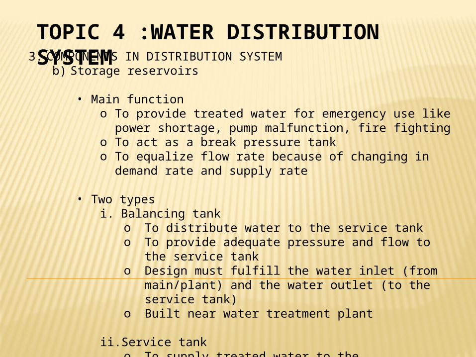
iv. Tracer gas – a portable gas sensor is used to detect nontoxic gas as it escaped thru leaks in pipe and rises thru the surrounding soil to the ground surface

4. NON REVENUE WATERe) Piping design with Hazen Williams formula
Factors affecting the design• Flow velocity - normal 2.5 m/s, in pump station must
below 1.2 m/s to cope cavitations problem• Peak demand - because of difference in hourly
demand• Fire fighting flow• Recommended pressure residue - to balance the
demand and supply• Minimum diameter - 150mm for housing area
Easy to use for pressured pipe because of simple calculation
only use scientific calculator and need no graph chart However, it has range of accuracy because limitation
factor Not suitable in diameter less than 50mm and velocity 3
m/s