Embed Size (px)
Citation preview

CC-THERM
User’s Guide And Tutorial

i
LICENSE AGREEMENT
LICENSOR: Chemstations Inc. 2901 Wilcrest Drive, Suite 305 Houston, Texas 77042 U.S.A.
ACCEPTANCE OF TERMS OF AGREEMENT BY THE USER
YOU SHOULD CAREFULLY READ THE FOLLOWING TERMS AND CONDITIONS BEFORE USING THIS PACKAGE. USING THIS PACKAGE INDICATES YOUR ACCEPTANCE OF THESE TERMS AND CONDITIONS.
The enclosed proprietary encoded materials, hereinafter referred to as the Licensed Program(s), are the property of Chemstations Inc. and are provided to you under the terms and conditions of this License Agreement. Included with some Chemstations Inc. Licensed Programs are copyrighted materials owned by the Microsoft Corporation, Rainbow Technologies Inc., and InstallShield Software Corporation. Where such materials are included, they are licensed by Microsoft Corporation, Rainbow Technologies Inc., and InstallShield Software Corporation to you under this License Agreement. You assume responsibility for the selection of the appropriate Licensed Program(s) to achieve the intended results, and for the installation, use and results obtained from the selected Licensed Program(s).
LICENSE GRANT
In return for the payment of the license fee associated with the acquisition of the Licensed Program(s) from Chemstations Inc., Chemstations Inc. hereby grants you the following non-exclusive rights with regard to the Licensed Program(s):
Use of the Licensed Program(s) on more than one machine. Under no circumstance is the Licensed Program to be executed without either a Chemstations Inc. dongle (hardware key) or system authorization code.
You agree to reproduce and include the copyright notice as it appears on the Licensed Program(s) on any copy, modification or merged portion of the Licensed Program(s).
THIS LICENSE DOES NOT CONVEY ANY RIGHT TO USE, COPY, MODIFY OR TRANSFER THE LICENSED PROGRAM(S) OR ANY COPY, MODIFICATION OR MERGED PORTION THEREOF, IN WHOLE OR IN PART, EXCEPT AS EXPRESSLY PROVIDED IN THIS LICENSE AGREEMENT.
TERM
This License Agreement is effective upon acceptance and use of the Licensed Program(s) until terminated in accordance with the terms of this License Agreement. You may terminate the License Agreement at any time by destroying the Licensed Program(s) together with all copies, modifications, and merged portions thereof in any form. This License Agreement will also terminate upon conditions set forth elsewhere in this Agreement or automatically in the event you fail to comply with any term or condition of this License Agreement. You hereby agree upon such termination to destroy the Licensed Program(s) together with all copies, modifications and merged portions thereof in any form.
ii
LIMITED WARRANTY
The Licensed Program(s), i.e. the tangible proprietary software, is provided "AS IS" WITHOUT WARRANTY OF ANY KIND, EITHER EXPRESSED OR IMPLIED, AND EXPLICITLY EXCLUDING ANY IMPLIED WARRANTIES OF MERCHANTABILITY OR FITNESS FOR A PARTICULAR PURPOSE. The entire risk as to the quality and performance of the Licensed Program(s) is with you.
Some jurisdictions do not allow the exclusion of limited warranties, and, in those jurisdictions the above exclusions may not apply. This Limited Warranty gives you specific legal rights, and you may also have other rights which vary from one jurisdiction to another.
Chemstations Inc. does not warrant that the functions contained in the Licensed Program(s) will meet your requirements or that the operation of the program will be uninterrupted or error free.
Chemstations Inc. does warrant, however, that the diskette(s), i.e. the tangible physical medium on which the Licensed Program(s) is furnished, to be free from defects in materials and workmanship under normal use for a period of ninety (90) days from the date of delivery to you as evidenced by a copy of your receipt.
Chemstations Inc. warrants that any program errors will be fixed by Chemstations Inc., at Chemstations' expense, as soon as possible after the problem is reported and verified. However, only those customers current on their update/maintenance contracts are eligible to receive the corrected version of the program.
ENTIRE AGREEMENT
This written Agreement constitutes the entire agreement between the parties concerning the Licensed Program(s). No agent, distributor, salesman or other person acting or representing themselves to act on behalf of Chemstations Inc. has the authority to modify or supplement the limited warranty contained herein, nor any of the other specific provisions of this Agreement, and no such modifications or supplements shall be effective unless agreed to in writing by an officer of Chemstations Inc. having authority to act on behalf of Chemstations Inc. in this regard.
LIMITATIONS OF REMEDIES
Chemstations' entire liability and your exclusive remedy shall be:
a) The replacement of any diskette not meeting Chemstations' "Limited Warranty" as defined herein and which is returned to Chemstations Inc. or an authorized Chemstations dealer with copy of your receipt, or
b) If Chemstations Inc. or the dealer is unable to deliver a replacement diskette which is free of defects in materials or workmanship, you may terminate this License Agreement by returning the Licensed Program(s) and associated documentation and you will be refunded all monies paid to Chemstations Inc. to acquire the Licensed Program(s).
IN NO EVENT WILL CHEMSTATIONS INC. BE LIABLE TO YOU FOR ANY DAMAGES, INCLUDING ANY LOST PROFITS, LOST SAVINGS, AND OTHER INCIDENTAL OR CONSEQUENTIAL DAMAGES ARISING OUT OF THE USE OR INABILITY TO USE THE LICENSED PROGRAM(S) EVEN IF CHEMSTATIONS INC. OR AN AUTHORIZED CHEMSTATIONS DEALER HAS BEEN ADVISED OF THE POSSIBILITY OF SUCH DAMAGES, OR FOR ANY CLAIM BY ANY OTHER PARTY.
SOME JURISDICTIONS DO NOT PERMIT LIMITATION OR EXCLUSION OF LIABILITY FOR INCIDENTAL AND CONSEQUENTIAL DAMAGES SO THAT THE ABOVE LIMITATION AND EXCLUSION MAY NOT APPLY IN THOSE JURISDICTIONS.
iii
GENERAL
The initial license fee includes one (1) year of support, maintenance, and enhancements to the program. After the first one (1) year term, such updates and support are optional at the then current update fee.
Questions concerning this License Agreement and all notices required herein shall be made by contacting Chemstations Inc. in writing at Chemstations Inc., 2901 Wilcrest, Suite 305, Houston, Texas, 77042, by telephone, 713-978-7700, or by Fax, 713-978-7727.
DISCLAIMER: CC-STEADY STATE, CC-BATCH, CC-DYNAMICS, CC-THERM, CC-FLASH, CC-SAFETY NET, CC-POLYMERS, CC-LANPS
Copyright(c) Chemstations Inc., 2004, all rights reserved.
This proprietary software is the property of Chemstations Inc. and is provided to the user pursuant to a Chemstations Inc. program license agreement containing restrictions on its use. It may not be copied or distributed in any form or medium, disclosed to third parties, or used in any manner except as expressly permitted by the Chemstations Inc. program license agreement.
THIS SOFTWARE IS PROVIDED "AS IS" WITHOUT WARRANTY OF ANY KIND, EITHER EXPRESS OR IMPLIED. NEITHER CHEMSTATIONS INC. NOR ITS AUTHORIZED REPRESENTATIVES SHALL HAVE ANY LIABILITY TO THE USER IN EXCESS OF THE TOTAL AMOUNT PAID TO CHEMSTATIONS INC. UNDER THE CHEMSTATIONS INC. PROGRAM LICENSE AGREEMENT FOR THIS SOFTWARE. IN NO EVENT WILL CHEMSTATIONS INC. BE LIABLE TO THE USER FOR ANY LOST PROFITS OR OTHER INCIDENTAL OR CONSEQUENTIAL DAMAGES ARISING OUT OF USE OR INABILITY TO USE THE SOFTWARE EVEN IF CHEMSTATIONS INC. HAS BEEN ADVISED AS TO THE POSSIBILITY OF SUCH DAMAGES. IT IS THE USERS RESPONSIBILITY TO VERIFY THE RESULTS OF THE PROGRAM.

iv
Revised 5/24/04 i
CC-THERM FOR WINDOWS 5.4 TABLE OF CONTENTS CC-THERM SHELL AND TUBE Product Overview .........................................................................................................................1 Introduction to CC-THERM .........................................................................................................................1 Easy to Learn .........................................................................................................................1 Installation .........................................................................................................................1 Technical Features for Shell and Tube.......................................................................................................1 Heat Transfer Methods .........................................................................................................................2 Evaporation .........................................................................................................................2 Thermosyphons .............................................................................................................3 Falling Films...................................................................................................................4 Pool Evaporation............................................................................................................5 Forced Evaporation........................................................................................................5 Condensation .........................................................................................................................6 Shellside Condensation .................................................................................................6 Tubeside Condensation .................................................................................................7 Multi-Component Condensation and the Effect of Non-Condensibles ...........................7 Condensate Retention on Low Fin Tubes ......................................................................7 Sensible Heat Transfer.................................................................................................................8 Sensible Flow – Tubeside ..............................................................................................8 Sensible Flow – Shellside ..............................................................................................8 The Zone Analysis........................................................................................................................8 Output Features .........................................................................................................................8 Overview .........................................................................................................................9 Summary .......................................................................................................................10 CC-THERM Commands .......................................................................................................................10 Data Entry in CC-THERM .......................................................................................................................13 Utility Streams .......................................................................................................................14 Heat Curve Generation .......................................................................................................................15 Heat Curve Input .......................................................................................................................15 Cutting Method.............................................................................................................15 Wall Type ....................................................................................................................16 Number of Cutting Points .............................................................................................16 Edit Heat Curves .......................................................................................................................16 General Specifications .......................................................................................................................17 The General Information Tab .....................................................................................................18 The Modeling Methods Tab........................................................................................................21 The Design Options Dialog Box................................................................................................................23 Design Criteria .......................................................................................................................24 Sizing Nozzles .......................................................................................................................25 Limits of Design Variables..........................................................................................................25
Revised 5/24/04 ii
The Thermosyphon Reboiler Dialog Box..................................................................................................25 Inlet Pipe ......................................................................................................................27 Outlet Pipe ......................................................................................................................27 Exchanger Geometry ......................................................................................................................28 Tubes ......................................................................................................................28 Shell ......................................................................................................................30 Baffles ......................................................................................................................31 Nozzles ......................................................................................................................33 Clearances ......................................................................................................................34 Materials ......................................................................................................................37 Miscellaneous ......................................................................................................................37 Calculate ......................................................................................................................38 View Results ......................................................................................................................38 Summary Results ......................................................................................................................39 Shellside Data ......................................................................................................................39 Tubeside Data ......................................................................................................................39 Baffle Data ......................................................................................................................40 Clearance Data ......................................................................................................................40 Overall Data ......................................................................................................................40 Tabulated Data ......................................................................................................................40 Heat Curves ......................................................................................................................40 Zone-by-Zone Data ....................................................................................................................40 Vibration ......................................................................................................................40 Optimization ......................................................................................................................40 Stream Data ......................................................................................................................41 Reboiler Data ......................................................................................................................41 TEMA Sheet ......................................................................................................................41 Input Data Report ......................................................................................................................41 Plot ......................................................................................................................41 Heat Curve ......................................................................................................................41 Heat Flux ......................................................................................................................41 LMTD ......................................................................................................................41 Temperature ......................................................................................................................41 Heat XFER Coefficient ...............................................................................................................42 Heat XFER Area ......................................................................................................................42 Report Generation ......................................................................................................................42 Prepare Labels ......................................................................................................................42 Select Reports ......................................................................................................................43 Generate Reports ......................................................................................................................44 Save Configuration ......................................................................................................................44 Re-Enter Stream Information....................................................................................................................44 Re-Initialize Exchanger ......................................................................................................................44 CC-THERM Output ......................................................................................................................44 Summary Report ......................................................................................................................44 TEMA Sheet ......................................................................................................................46 Heating Curves ......................................................................................................................48
Revised 5/24/04 iii
Shellside Data .......................................................................................................................48 Tubeside Data .......................................................................................................................51 Tabulated Data .......................................................................................................................52 Zone-By-Zone Analysis .......................................................................................................................54 Clearance .......................................................................................................................60 Overall Data .......................................................................................................................60 Vibration Analysis .......................................................................................................................62 Optimization .......................................................................................................................65 Stream Data .......................................................................................................................66 Reboiler Data .......................................................................................................................66 Input Data Report .......................................................................................................................67 CC-THERM Tutorial .......................................................................................................................68 The Condensate Stabilizer Problem .........................................................................................................68 Entering CC-THERM .......................................................................................................................69 Step 1: Identify the Tubeside Stream...........................................................................70 Step 2: Generate the Heat Curve.................................................................................70 Step 3: Making General Specifications ........................................................................71 Step 4: The Tube Specifications Dialog Box ................................................................73 Step 5: The Shell Specifications Dialog Box ................................................................74 Step 6: The Baffle Specifications Dialog Box ...............................................................75 Step 7: The Nozzle Specifications Dialog Box .............................................................77 Step 8: The Clearances Specifications Dialog Box ......................................................77 Step 9: The Materials Specifications Dialog Box..........................................................78 Step 10: The Miscellaneous Specifications Dialog Box................................................79 Step 11: Calculating .....................................................................................................80 Step 12: Using the View and Plot Commands .............................................................80 Step 13: Generating a Report ......................................................................................83 Appendix I: Material Code Numbers for Shell and Channel Materials ......................................................85 Shell Materials .......................................................................................................................85 Channel Materials ......................................................................................................................87 DIN-A.D. Merkblatter Code ..........................................................................................89 British Standard 5500...................................................................................................90 Appendix II: Material Code Numbers for Tubesheet Materials .................................................................91 ASME Code .......................................................................................................................91 Appendix III: TEMA Designations .............................................................................................................94 Appendix IV: Fin Tubes .......................................................................................................................95 Appendix V: User Fintubes .....................................................................................................................105 The Fintube Methods Dialog Box............................................................................................................106 The Fintube Specifications Dialog Box ...................................................................................................107 Appendix VI: CHEMCAD THERM References .......................................................................................112 Evaporation .....................................................................................................................112 Condensation .....................................................................................................................113 Sensible Flow .....................................................................................................................114
Revised 5/24/04 iv
CC-THERM AIR COOLER Product Overview ....................................................................................................................115 Introduction to CC-THERM Air Cooler....................................................................................................115 Easy to Learn ....................................................................................................................115 Technical Features ....................................................................................................................115 Methods ....................................................................................................................115 Tubeside Heat Transfer ...........................................................................................................116 Condensation.............................................................................................................116 Multi-Component Condensation ................................................................................117 Sensible Flow ............................................................................................................117 Airside Heat Transfer ...............................................................................................................117 Zone Analysis ....................................................................................................................117 Output Features ....................................................................................................................118 Overview ....................................................................................................................118 Summary ....................................................................................................................119 Air Cooler Commands ....................................................................................................................120 Using Air Cooler Menus ....................................................................................................................121 Data Entry in Air Cooler ....................................................................................................................121 Air Side Data ....................................................................................................................122 Heat Curve Generation ....................................................................................................................124 Edit Heat Curve ....................................................................................................................125 General Specification ....................................................................................................................126 Exchanger Geometry ....................................................................................................................128 Tube ....................................................................................................................128 Bundle ....................................................................................................................130 Nozzles ....................................................................................................................131 Miscellaneous ....................................................................................................................132 Materials ....................................................................................................................133 Fan Parameters ....................................................................................................................134 Calculate ....................................................................................................................138 View Results ....................................................................................................................138 Streams ....................................................................................................................139 Heat Curves ....................................................................................................................139 Tabulated Data ....................................................................................................................139 API Data ....................................................................................................................139 Zone-By-Zone Data..................................................................................................................139 Optimization ....................................................................................................................140 Plot ....................................................................................................................140 Heat Curve ....................................................................................................................140 Heat Flux ....................................................................................................................140 LMTD ....................................................................................................................140 Temperature ....................................................................................................................141 Heat XFER Coefficient .............................................................................................................141 Heat XFER Area ....................................................................................................................141 Re-Enter Stream Information..................................................................................................................141
Revised 5/24/04 v
Air Cooler Output .....................................................................................................................142 Stream Data .....................................................................................................................142 Heat Curves .....................................................................................................................143 Tabulated Data .....................................................................................................................144 API Data .....................................................................................................................148 Zone-By-Zone Data..................................................................................................................151 Optimization .....................................................................................................................156 CC-THERM PLATE HEAT EXCHANGER Product Overview .....................................................................................................................159 Introduction to CC-THERM Plate Heat Exchanger .................................................................................159 Easy to Learn .....................................................................................................................159 Technical Features .....................................................................................................................159 Methods .....................................................................................................................159 Output Features .....................................................................................................................159 Overview .....................................................................................................................160 Summary .....................................................................................................................161 Plate Heat Exchanger Commands..........................................................................................................162 Using Plate Heat Exchanger Menus .......................................................................................................163 Data Entry in Plate Heat Exchanger .......................................................................................................163 Heat Curve Generation .....................................................................................................................164 Edit Heat Curve .....................................................................................................................165 General Specification .....................................................................................................................165 Exchanger Geometry .....................................................................................................................167 Plate .....................................................................................................................167 Unit .....................................................................................................................168 Nozzles .....................................................................................................................169 Materials .....................................................................................................................170 Calculate .....................................................................................................................171 View Results .....................................................................................................................171 Stream .....................................................................................................................171 Heat Curves .....................................................................................................................171 Tabulated Data .....................................................................................................................172 Re-Enter Stream Information..................................................................................................................172 Plate Heat Exchanger Output .................................................................................................................173 Stream Data .....................................................................................................................173 Heat Curves .....................................................................................................................173 Tabulated Data .....................................................................................................................175 Appendix I Plate Heat Exchanger References........................................................................................178 CC-THERM DOUBLE PIPE Product Overview .....................................................................................................................179 Introduction to CC-THERM Double Pipe ................................................................................................179 Easy to Learn .....................................................................................................................179
Revised 5/24/04 vi
Technical Features ....................................................................................................................179 Heat Transfer Methods ....................................................................................................................179 Sensible Heat Transfer ............................................................................................................179 Sensible Flow – Tubeside..........................................................................................179 Sensible Flow – Shellside..........................................................................................180 The Zone Analysis ...................................................................................................................180 Output Features ....................................................................................................................180 Overview ....................................................................................................................180 Summary ....................................................................................................................182 Double Pipe Commands ....................................................................................................................182 Data Entry in Double Pipe ....................................................................................................................184 Heat Curve Generation ....................................................................................................................185 Heat Curve Input ....................................................................................................................185 Cutting Method ..........................................................................................................185 Number of Cut Points.................................................................................................186 Utility Streams ....................................................................................................................186 Edit Heat Curve ....................................................................................................................187 General Specifications ....................................................................................................................187 The General Page....................................................................................................................188 The Methods Page...................................................................................................................189 Exchanger Geometry ....................................................................................................................190 Tubes ....................................................................................................................191 Shell ....................................................................................................................193 Nozzles ....................................................................................................................194 Materials ....................................................................................................................194 Calculate ....................................................................................................................195 View Results ....................................................................................................................195 Summary Results ....................................................................................................................195 Shellside Data ....................................................................................................................196 Tubeside Data ....................................................................................................................196 Overall Data ....................................................................................................................196 Tabulated Data ....................................................................................................................196 Heat Curves ....................................................................................................................196 Zone By Zone Data ..................................................................................................................196 Stream Data ....................................................................................................................196 Tema Sheet ....................................................................................................................196 Plot ....................................................................................................................197 Heat Curve ....................................................................................................................197 Heat Flux ....................................................................................................................197 LMTD ....................................................................................................................197 Temperature ....................................................................................................................197 Heat XFER Coefficient .............................................................................................................198 Heat XFER Area ....................................................................................................................198 Report Generation ....................................................................................................................198 Prepare Labels ....................................................................................................................198 Select Reports ....................................................................................................................199
Revised 5/24/04 vii
Generate Reports .....................................................................................................................199 Save Configuration .....................................................................................................................199 Re-enter Stream Information ..................................................................................................................200 Re-Initialize Exchanger .....................................................................................................................200 CC-THERM Double Pipe Output ............................................................................................................201 Summary Report .....................................................................................................................201 Tema Sheet .....................................................................................................................202 Heating Curves .....................................................................................................................204 Shellside Data and Tubeside Data .........................................................................................................204 Tabulated Data .....................................................................................................................205 Zone By Zone Analysis .....................................................................................................................206 Overall Data .....................................................................................................................208 Stream Output .....................................................................................................................209 Appendix I: Material Code Numbers For Tube Materials ........................................................................210 Appendix II: Double Pipe References.....................................................................................................214 Sensible Flow.............................................................................................................214
CC-THERM
SHELL & TUBE
User’s Guide And Tutorial

CC-THERM Version 5.4 User’s Guide
1
PRODUCT OVERVIEW
INTRODUCTION TO CC-THERM
CC-THERM is an integrated module for the design and rating of double pipe, shell and tube, plate and frame and air cooled heat exchangers in the CHEMCAD Suite. The program will design and rate any type of shell and tube heat exchanger, sensible/sensible service plate and frame heat exchangers and air coolers . CC-THERM is fully integrated with the CHEMCAD Suite so process data is automatically transferred from the process flowsheets to the heat exchanger analysis, and heating curves and physical properties data are automatically generated using the same properties and methods. The first part of this user guide covers tube and shell heat exchanger calculations.
EASY TO LEARN
The input for CC-THERM is simple and concise. It is based upon the CHEMCAD input system, so anyone familiar with the CHEMCAD Suite will be able to operate CC-THERM with ease.
Since the input/output systems and conventions are the same in CC-THERM as those used in CHEMCAD, please refer to the CHEMCAD User’s Guide for these types of “How to” instructions.
INSTALLATION
By default CC-THERM is always installed with the CHEMCAD Suite. If any programs of the CHEMCAD Suite have been installed, there is not any special procedure to install CC-THERM because it is completely integrated with the CHEMCAD Suite and does not run in a separate interface. The use of CC-THERM only depends on the user’s license. Please refer to the installation section of the CHEMCAD User’s Guide.
TECHNICAL FEATURES FOR SHELL AND TUBE
1. CC-THERM handles the following applications.
• Fluid and thermosyphon reboilers
• Forced circulation evaporators
• Horizontal or vertical condensers
• Falling film evaporators and heaters
• Vertical thermosyphons
User’s Guide CC-THERM Version 5.4
2
• Reflux condensers
• Sensible heat, both liquid and vapor
2. Three modes of calculation may be selected: Rating mode, fouling factor rating or design mode. In the design mode, a full optimization of shell diameter, tube lengths and baffle spacing will be carried out. Optionally, an optimization of tube passes can be carried out.
3. All TEMA-type exchangers.
4. Six types of baffles can be used: Single segmental, double segmental, triple segmental, no-tubes-in-window, disk and donut, and rod baffles.
5. A complete vibration analysis is performed for all types of exchangers.
6. You may use TEMA clearances or input your own clearances.
7. Sealing strips are permitted.
8. Tube counts are calculated.
9. Impingement plates can be handled.
10. Tubes may be bare or fin. A library of Wolverine, HPTI, and Wieland tubes are built into the program.
11. Turbulators may be used on the inside of the tube.
12. Dry wall and wet wall condensing can be accommodated.
13. A variety of heat transfer and pressure drop methods are available.
14. Heat exhangers sizes that are below those covered by TEMA, ASME, DIN, and BS5500 can be handled.
15. A tabulated pressure drop distribution report through shell and tube heat exchangers is provided.
HEAT TRANSFER METHODS
EVAPORATION
The program considers these various types of evaporation.
Shellside Tubeside
Thermosyphon Reboiler Thermosyphon Reboiler
Pool-Type Evaporation (Kettle) Falling-Film Evaporation
Forced Evaporation Forced Evaporation
CC-THERM Version 5.4 User’s Guide
3
Thermosyphons: The calculation of a thermosyphon reboiler is similar for both the shellside and the tubeside. In both cases, the program combines the nucleate boiling and the two-phase convective heat transfer. The computation of the tube wall temperature is of importance in the calculation. A calculation for subcooled boiling when a substantial amount of subcooling is present is performed. The minimum amount of superheat necessary to initiate subcooled boiling is computed and compared to the tube wall temperature. If the tube wall temperature is sufficiently high, a nucleate boiling coefficient is calculated, but proportioned according to the amount of subcooling present (the more the subcooling, the lower the coefficient).
The program will complete the thermosyphon circulation rate (if so requested) by balancing the pressure drops to the available head. The user can specify details of the inlet and outlet piping, elevations, and the available head. In order to maintain a heat balance (that is, to keep the exchanger heat duty equal to its specified value), a constant vapor generation rate is assumed on the thermosyphon side.
The following steps are used for thermosyphons.
1. Calculate the static head of the column liquid.
2. Calculate pressure drop in the inlet piping and nozzle.
3. Calculate the new saturation temperature based on the pressure at the inlet to the exchanger.
4. Go through each zone of the exchanger and iterate on the pressure drop in each zone. Once the pressure drop is converged, the saturation temperature is also updated and the LMTD is recalculated. Thus the program makes a rigorous calculation of the boiling point rise and always gives the correct LMTD.
5. Calculate the pressure drop in the outlet piping once the program goes through the last zone.
6. The program will leave the amount vaporized and vary the vapor-liquid split until the loop is converged.
The calculation of the two-phase density and the two-phase pressure drop is critical to the success of this calculation. Previously, the Nelson modification of the Lockhart-Martinelli equation was used to calculate the two-phase density and pressure drop. However, more recently published correlations have proven to be far more accurate and now supplant the Lockhart-Martinelli method. For the two-phase density calculation, the CISE method, which is superior to Lockhart-Martinelli, is used since it takes into account the mass flow effect on the two-phase density.
For the two-phase pressure drop calculation, the program uses both the Baroczy method and the Friedel correlation and basically uses an average of the two results.
For the heat transfer coefficients for tubeside thermosyphons, the Chen method is used for both two-phase convection boiling and the nucleate boiling coefficients. The nucleate boiling coefficient used by Chen is that of Forster and Zuber (developed for boiling on the outside of tubes) and modified to take into account the lower wall superheat inside the tubes. The basic Forster and Zuber equation calculates the nucleate boiling coefficient on the outside of tubes for shellside evaporation.
User’s Guide CC-THERM Version 5.4
4
The critical heat flux is determined for both the shellside and the tubeside. The critical heat flux for the shellside is obtained by calculating the one-tube critical heat flux (as proposed by Kutaladze-Zuber) and multiplying this by the bundle correction factor (originally from Palen and later modified by Grant). The critical heat flux for the tube side (proposed by Bowring) is that flux at which dryout begins to occur.
Falling Films: A falling-film exchanger is computed for both a liquid being heated or cooled and for a liquid being evaporated. Only falling films inside the tubes are considered. Falling films on the outside of the tubes (the shellside) do exist, but because they are rare, the program does not handle them presently. The calculation suggested by Dukler in the above-mentioned reference is used. The program follows the procedures below.
1. Breaks the calculation into n (default=10) zones.
2. Determine a certain heat load increment and a defined vapor and liquid flow for each zone from the heat curve.
3. Calculates the hydrodynamics.
4. Assumes a certain pressure drop and loops through each zone several times until the assumed pressure drop converges on the actual pressure drop.
5. Once the pressure drop is converged, the vapor shear at the wall is computed. A non-dimensional parameter named BETA (same name used in original Dukler paper) is printed. This parameter indicates the magnitude of the effect of the vapor shear. This term increases in proportion to the amount of liquid evaporated. As this term increases, the turbulence of the film increases. There is also a correlation between a high BETA and the thinning-out of the film. The thinner the film, the higher the heat transfer coefficient.
6. Next the program decides whether the regime is laminar or turbulent once the BETA term is calculated. The Reynold's number is determined in a similar fashion to Dukler and follows closely his recommendations for the definition of laminar and turbulent flow. The cutoff points between turbulent and laminar flow will be different depending on whether the process type is a falling film being heated (or cooled) or a falling film being evaporated. Chun and Seban claim that a weber number of the order unity is a better indicator of the transition between laminar and turbulent flow. However, the program still uses the Reynold's number to decide whether the regime is laminar or turbulent. The program arbitrarily uses a transition Reynold's number, which varies between 800 and 3000. If the vapor shear is high, the program goes as low as 800. If vapor shear is very low, the program uses a transition number of 3000.
7. Once the flow regime is established, the film thickness is calculated. The boiling mechanism is two-phase convective boiling with the boiling taking place at the liquid-vapor interface. The heat transfer phenomenon through the film is one of conduction, and, therefore, the heat transfer coefficient is determined by the thickness of the film. Nucleate boiling at the tube wall should usually be avoided. The superheat at the wall necessary for incipient nucleate boiling is determined. In a well-designed unit, the tube wall temperature should be below the temperature at which nucleate boiling begins. The program prints the tube wall temperature and the temperature of the onset of the nucleate boiling at each zone of the calculation. If the product being evaporated is not
CC-THERM Version 5.4 User’s Guide
5
temperature-sensitive, nucleate boiling may not be acceptable. The boiling coefficient will almost always be as high or higher than the falling film coefficient being calculated. However, once nucleate boiling commences, the phenomenon occurring is no longer convective boiling from a falling film, but rather nucleate boiling at the tube wall. When a temperature-sensitive product is present, the user should analyze the program results carefully. In order to avoid nucleate boiling at the wall, decreasing the shellside temperature may be necessary in order to bring the wall to a temperature below the superheat for the onset of nucleation. The program does not make this temperature change automatically.
Avoidance of dry patch formation is a problem in a falling film exchanger. The program prints the minimum Reynold's number at which the circumference of the tube wall will remain wet. The Reynold's number of the calculation should be comfortably above this minimum in order to avoid streaking and patch formation.
Pool Evaporation: In the calculation of a pool-type evaporator, the program considers the coefficient to be mostly nucleate boiling although it does consider the effect of natural convection. The calculation of the nucleate boiling coefficient is by Forster-Zuber. The critical heat flux for the shellside is obtained by calculating the one-tube critical heat flux (as proposed by Kutaladze-Zuber) and multiplying this by the bundle correction factor, originally from Palen and later modified by Grant.
Forced Evaporation: For all types of evaporators, the program considers the simultaneous occurrence of nucleate boiling and two-phase convective boiling. In cases where the amount evaporated is relatively small, the program gives more weight to the nucleate boiling mechanism. Conversely, when a substantial amount is evaporated, more weight is given to the two-phase convective boiling coefficients. As with a thermosyphon reboiler, the tube wall temperature is elaborately calculated since this has a profound effect on the nucleate boiling coefficient. When the fluid is almost entirely evaporated, the program essentially calculates a gas coefficient. If any superheat is present, the coefficient in this region is essentially a gas coefficient. Chen's two-phase forced convection coefficient is used for tubeside evaporation. The two-phase forced convection coefficient for shellside evaporation is, essentially, the shellside coefficient calculated as though the flow were all liquid. The program then multiplies this coefficient by a suitable two-phase correction factor, empirical in nature and based on experience. The nucleate boiling coefficient is the method of Forster-Zuber.
When forced evaporation inside the tubes exists and the entering liquid has a lot of subcooling, a twisted-tape insert to promote turbulence (and the heat transfer coefficient) for the subcooled liquid is commonly employed. Such twisted-tape inserts are available in the fin tube databank.
User’s Guide CC-THERM Version 5.4
6
CONDENSATION
The program considers the following types of condensation.
Shellside Tubeside
Horizontal Condensation Horizontal Condensation
Vertical Condensation Vertical Condenser
Reflux Condenser
The program calculates tubeside condensation for both vertical and horizontal condensers, shellside condensation for both horizontal and vertical condensers, and a reflux (or knock-back) condenser for vertical in-tube condensation. The algorithm for both shellside and tubeside condensation is similar because the exchanger is always broken into n (default=10) different zones. The two principal heat transfer mechanisms occurring (shear-controlled condensation and gravity-controlled condensation) are always computed for all types of condensers. In between these two extreme zones, the calculation is considered to be in the transition region between shear-controlled and gravity controlled. For a condenser where the inlet quality is 100% and the outlet 0%, the flow regime usually is shear-controlled at the inlet, goes through the transition region, and, finally, is gravity controlled at the outlet. When a large amount of vapor is present and vapor velocity is very high, the forces on the condensing film are mostly from the interfacial shear of the vapor and the gravity forces on the film are negligible by comparison.
The pressure drop computations for condensation are similar to the evaporation methods described above. The CISE method for the two-phase density calculation is employed. Both the Baroczy method and the Friedel correlation are utilized for vapor evaporation, and basically an average of the two results is used in the calculation of the two-phase pressure drop.
For a tubeside thermosyphon, the static head of the vapor-liquid mixture in the tubes always result in a pressure drop because we are proceeding opposite to the direction for the gravity as we go up the tubes. The situation in a vertical condenser is the opposite. We are proceeding in the same direction as gravity and instead of a pressure loss, we have a gain or a negative loss. For some runs, this pressure gain is larger than the pressure loss due to the combined effects of momentum and friction and, thus, the sum of the losses can be a negative number (this may appear unusual but, in fact, it is a real possibility). Three separate effects for the overall pressure drop are considered: frictional, momentum, and gravity effects.
Shellside Condensation: The program uses the Nusselt equation for gravity condensation on the outside of the tube banks up to a Reynold's number of 1000. Above a Reynold's number of 1000, the equation is too conservative. Thereafter, the semi-empirical equation of Labuntso is employed to predict the gravity coefficient in the turbulent region. The cutoff Reynold's number of 1000 is an arbitrary choice. Cutoff values in the literature usually vary between 800 and 1600. The shellside shear-controlled coefficient is determined in a method similar to that used for forced evaporation on the shellside. The shellside coefficient is computed as if the flow were all liquid. This coefficient is then multiplied by a suitable two-phase correction factor, empirical in nature and based on experience.
CC-THERM Version 5.4 User’s Guide
7
Tubeside Condensation: The program uses the Dukler method for gravity condensation for vertical tubes. This method is described under Falling Film Evaporators. The Nusselt equation is used for gravity condensation inside horizontal tubes. The flow in the horizontal tube is assumed to be stratified flow, not annular flow. The Boyko-Kruzhilin method is employed to calculate the shear-controlled coefficient for condensation in horizontal tubes.
The program also calculates a reflux or knock-back condenser often used on the top of a column. In this type of exchanger, the vapor flows up the tubes, and the condensate flows counter-current down the tubes, back into the column. This exchanger is similar to a vertical tubeside condenser except that a vertical has co-current vapor and liquid flow while the reflux has counter-current flow. The flooding velocity at the bottom of the tubes must be checked for the reflux condenser.
Multi-Component Condensation and the Effect of Non-Condensibles: All above-mentioned methods are for condensation of a pure vapor and, as such, do not take into account the presence of non-condensibles or the effect of large temperature differences between the vapor dew point and bubble point.
To account for the presence of non-condensibles or large temperature differences between inlet and outlet, a method similar to that suggested by Silver and Bell & Khaly in the above-cited references is utilized. For each step along the condensation curve, the program calculates a resistance factor to include the combined effects of a large temperature difference and the presence of non-condensibles. A very common occurrence is a steam condenser in the presence of a small quantity of air. This type gives a graphic illustration of how these resistance factors come into play. For the first several zones of such an exchanger, the condensing temperature is practically isothermal because only a small amount of air is present. In the last zone, a sizable temperature difference may exist and the amount of non-condensibles may become more significant since almost the entire vapor has condensed. Thus, the resistance factor in this last zone could be substantial, and, in such a case, half of the required area is often necessary for the last zone alone.
Condensate Retention on Low Fin Tubes: A horizontal shellside condenser with low radial fin tubes is a very common type of exchanger, especially in the refrigeration industry. Typically in a refrigeration circuit, Freon 12 or Freon 22 will evaporate in the tubes of the chiller and condense on the shellside of a condenser. The coefficients for Freon condensing on bare tubes are not particularly high. Coefficients for water flowing inside a tube are usually high. This presents an excellent opportunity for using low radial fin tubes since the in-tube coefficient is high (even after relating to tube outer surface). Also the shellside condensing coefficient is not affected adversely by condensate retention effects of the fins since the surface tension of the freon is quite low. On the other hand, if steam is being condensed on the outside of a low radial fin tube, the condensing coefficient is reduced so drastically (because of the condensate retention effects of the fins) that it is almost never viable to use low fin radial tubes for steam condensing on their outside. If it is necessary to use some sort of undulation on the tube with steam condensing, a fluted tube is often used. A typical example of such a fluted tube is the Wolverine Korodense tube. A fluted tube has the additional advantage of being less rigid than a smooth tube and, thus, for similar operating conditions, may be less likely to overstress the tubes in a fixed tubesheet exchanger than a smooth tube. The program has a very extensive databank with low radial fin tubes from such manufacturers as Wolverine, HPTI, Wieland, etc.
User’s Guide CC-THERM Version 5.4
8
SENSIBLE HEAT TRANSFER
Sensible flow – Tubeside: The Sieder-Tate equation is employed for the calculation of the tubeside heat transfer coefficient in the turbulent region. The method of Martinelli and Boelter is utilized for laminar flow in a vertical tube. The method of Eubank and Proctor is used for laminar flow in horizontal tubes. Both of these correlations combine the effects of natural convection and forced convection. The flow is assumed to be laminar below a Reynold's number of 2000 and is turbulent above a Reynold's number of 10000. In the transition region, the program prorates the laminar and turbulent coefficient according to the Reynold's number to arrive at the final coefficient. The program uses the Blasius method for the friction factor in the pressure drop calculation for laminar flow (Reynold's number below 2000). For turbulent flow (Reynold's number above 3000) and for the transition region between laminar and turbulent flow, the recommendations made in Section 5 of Perry are followed.
The program has the heat transfer and pressure drop correlations for a twisted-tape turbulence promoter. It makes one complete revolution over a length equal to four internal diameters.
Sensible Flow – Shellside: For the coefficient of shellside crossing flow, the stream analysis method is the default. This method balances the pressure drop across the baffles for each of the possible flow paths. The following flow paths are considered.
Stream A is that flowing through the space between the tube outer diameter and the baffle hole. Stream B is the flow across the tube bundle. Stream C flows between the shell internal diameter and the outer tube limit. Stream E flows between the shell internal diameter and the baffle outer diameter. Stream F flows leaking through the empty spaces left by the tube pass partition.
Parallel flow model is used for calculating the coefficient when shell has no baffle; by setting baffle spacing greater than tube length. The program can also perform the calculation for rod baffles.
THE ZONE ANALYSIS
For a change-of-phase exchanger, the unit is analyzed using n (default =10) zones. CC-THERM automatically sets up the zones and properties of each zone, but permits the user to edit or override.
OUTPUT FEATURES
The user may select from the following output reports:
• Summary Report • TEMA Sheet • Heating Curves • Shell Side Data
CC-THERM Version 5.4 User’s Guide
9
• Tube Side Data • Tabulated Data • Zone-by-Zone Analysis • Baffle Data • Clearances Report • Overall Data • Vibration Analysis • Optimization • Stream Data • Reboiler Data
In addition to obtaining a hardcopy output report, you can review the results interactively on the screen and graphically using the plot features of the program.
OVERVIEW
CC-THERM is an interactive simulation tool for the design or rating of shell and tube, doublepipe, plate and frame and air-cooled heat exchangers. This section gives an overall view of the program usage and the options available on the CC-THERM menu for shell and tube heat exchangers. More information on each option is provided in later sections. The input functions allow you to enter process data by using dialog boxes with context specific help. With this input facility, you can create new problem files; review the results of problems already designed, and make modifications to previously saved problems.
There are six general steps involved in running a heat exchanger analysis with CC-THERM. The following list illustrates the general steps.
1. Define the problem and run the flowsheet.
2. Select the Sizing command on the menu bar. The Sizing Menu will open.
3. From this menu select the Shell & Tube option.
4. The program will prompt you through the initial setup of the exchanger analysis. At the end of the setup process, the CC-THERM Menu is displayed.
5. Inspect and edit the input as desired using the menu commands.
6. Execute the program.
7. Review and printout the results.
The program performs the following tasks.
1. Performs extensive error checking.
User’s Guide CC-THERM Version 5.4
10
2. Creates the streams for the use of one-sided heat exchangers, which include the condenser, reboiler, thermosyphon reboiler and pumparound.
3. Generates the heat curve for the tube and shell sides.
4. Calculates in any of the following modes:
i. Design - The inlet and outlet streams are taken from the flowsheet and the program selects the geometry and size of the exchangers (certain basic geometry specifications, such as TEMA type, must be specified by the user).
ii. Rating – The inlet and outlet streams are taken from the flowsheet and the user supplies the complete details of the exchanger geometry and dimensions. The program determines whether the exchanger is too large or too small for the given application.
iii. Fouling rating – The inlet and outlet streams are taken from the flowsheet and the user supplies the complete details of the exchanger geometry and dimensions. The program calculates the fouling factors required to obtain the specified performance from the exchanger. The inside and outside fouling factors are assumed to be equal.
iv. Simulation – In this mode the user supplies the complete details of the exchanger geometry and dimensions. The exchanger is then run as part of the flowsheet simulation. Thus, for any inlet streams coming into the exchanger, CC-THERM will calculate the outlet streams which the specified geometry would produce.
5. Generates the output for the design/analysis of the heat exchanger.
6. Provides an interactive user interface to allow the user to change the problem specifications to rerun the problem and review the results.
Creates the CC-THERM files to save all the input/output data for each exchanger.
SUMMARY
As an integrated module to CHEMCAD Suite, CC-THERM offers the process engineer an easy and comprehensive method of analyzing shell and tube heat exchangers. Since it uses the same command language as CHEMCAD, any CHEMCAD user can pick up the program in a matter of minutes. The program has been thoroughly and rigorously tested over a period of years in real life situations and found to be an accurate and reliable tool. It is fully supported by a staff of trained engineers.
CC-THERM COMMANDS
To run a tube and shell heat exchanger calculation in the CHEMCAD Suite, you must access the CC-THERM menu. This menu provides a set of commands, which are used to setup, run, review, and print out the analysis. This section describes the use of those commands in detail.

CC-THERM Version 5.4 User’s Guide
11
There are two procedures used to call the CC-THERM menu. The first method is described below (for design, rating and fouling rating calculations).
1. Run a simulation of a flowsheet containing a heat exchanger. A “heat exchanger” may be a column condenser, reboiler, or pump around as well as the process heat exchanger unit operation. CC-THERM must have a heat and material balance around the unit before it can rate or design it.
2. Select the Sizing command from the menu bar. The Sizing menu will open.
3. Highlight the Heat Exchanger option on the Sizing menu. A Heat Exchanger menu will open up.
4. Select the Shell & Tube option from the Heat Exchanger menu.
5. If a heat exchanger is not currently “selected”, the program will ask you to select one. If a heat exchanger is currently “selected” on the flowsheet, the program will assume this is the unit you want to design or rate.
6. If the selected heat exchanger has never been analyzed before, CC-THERM will walk you through the input procedure. This will involve identifying the tubeside stream (the shellside stream is then inferred), specifying utility streams (if necessary), and completing a series of dialog boxes. Once these have been completed (or at least viewed), the CC-THERM menu will appear.
If the selected heat exchanger has been analyzed before, this walk through procedure will be skipped and the CC-THERM menu will appear immediately.
The CC-THERM menu looks like this:
The options on this menu are briefly described below and more fully described in the following sections bearing the option as title.
It is possible to use CC-THERM directly in a CC-STEADY STATE or CC-DYNAMICS flowsheet simulation. This feature is called the “Simulation Mode” and is set up inside the HTXR module. In this mode the user must describe the exchanger geometry and dimensions to CHEMCAD. When the simulation comes around to the HTXR UnitOp, CC-THERM takes the inlet streams data and uses the specified geometry to determine how much heat is transferred, what the pressure drops are, and
User’s Guide CC-THERM Version 5.4
12
therefore what the outlet streams are. Thus the operation of a heat exchanger in a flowsheet simulation can be based upon heat transfer principles rather than solely upon thermodynamic specifications.
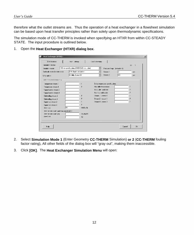
The simulation mode of CC-THERM is invoked when specifying an HTXR from within CC-STEADY STATE. The input procedure is outlined below.
1. Open the Heat Exchanger (HTXR) dialog box.
2. Select Simulation Mode 1 (Enter Geometry CC-THERM Simulation) or 2 (CC-THERM fouling
factor rating). All other fields of the dialog box will “gray out”, making them inaccessible.
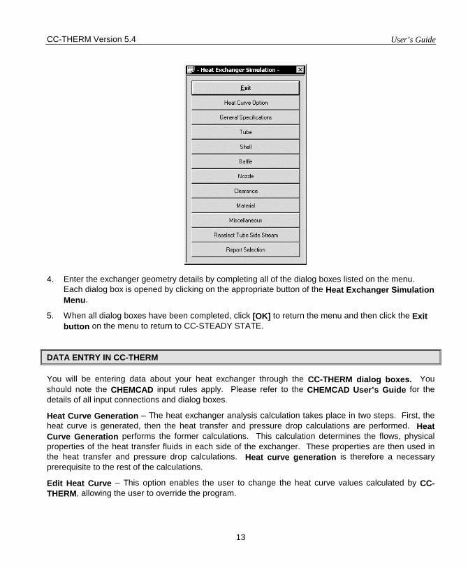
3. Click [OK]. The Heat Exchanger Simulation Menu will open:
CC-THERM Version 5.4 User’s Guide
13
4. Enter the exchanger geometry details by completing all of the dialog boxes listed on the menu.
Each dialog box is opened by clicking on the appropriate button of the Heat Exchanger Simulation Menu.
5. When all dialog boxes have been completed, click [OK] to return the menu and then click the Exit button on the menu to return to CC-STEADY STATE.
DATA ENTRY IN CC-THERM
You will be entering data about your heat exchanger through the CC-THERM dialog boxes. You should note the CHEMCAD input rules apply. Please refer to the CHEMCAD User’s Guide for the details of all input connections and dialog boxes.
Heat Curve Generation – The heat exchanger analysis calculation takes place in two steps. First, the heat curve is generated, then the heat transfer and pressure drop calculations are performed. Heat Curve Generation performs the former calculations. This calculation determines the flows, physical properties of the heat transfer fluids in each side of the exchanger. These properties are then used in the heat transfer and pressure drop calculations. Heat curve generation is therefore a necessary prerequisite to the rest of the calculations.
Edit Heat Curve – This option enables the user to change the heat curve values calculated by CC-THERM, allowing the user to override the program.
User’s Guide CC-THERM Version 5.4
14
General Specifications – This option is used to define basic exchanger parameters such as TEMA type (configuration), allowable pressure drops, fouling factors, maximum velocities, which heat transfer and pressure drop equations are to be used, and the calculation rate of the analysis.
Exchanger Geometry – Selecting this option allows the user to provide physical dimensions and orientations for the shell, tubes, baffles, nozzles, and clearances. It also allows the user to make material specifications.
Calculate – This is used to execute the thermal analysis and pressure drop calculations.
View Results – This item is used to view the calculated results interactively.
Plot – This option enables the user to graphically display a variety of heat curve, heat transfer, and pressure drop information on a zone-by-zone basis.
Report Generation – This command is used to generate hardcopies of tabulated reports. The user can select which information is to be included in the final report.
Save Configuration – This saves the current data.
Re-enter Stream Information – When a one-sided heat exchanger is selected from the CHEMCAD FLOWSHEET FOR DESIGN/RATING, THE USER MUST PROVIDE INFORMATION DEFINING THE SECOND SIDE IN ORDER FOR AN ANALYSIS TO BE PERFORMED. This is initially done in the “Heat Curve Generation” step. This command enables the user to change this second stream information.
Re-initialize Exchanger – This command completely deletes all data regarding the currently selected heat exchanger and restarts the input process.
Field by field descriptions of these options are provided below.
UTILITY STREAMS
If the heat exchanger uses a utility stream (for one sided-heat exchanger, reboiler, condenser or pumparound), CC-THERM will prompt for information defining this stream and its conditions.
The inlet composition and thermodynamic conditions are specified using a Stream dialog box just as in CHEMCAD. The program will calculate the utility flowrate, but an initial guess must be given.
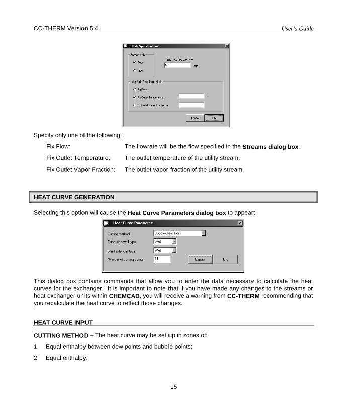
The utility stream flowrate is calculated based upon the heat duty of the exchanger and the outlet conditions of the stream. The outlet conditions are specified using the following dialog box:
CC-THERM Version 5.4 User’s Guide
15
Specify only one of the following:
Fix Flow: The flowrate will be the flow specified in the Streams dialog box.
Fix Outlet Temperature: The outlet temperature of the utility stream.
Fix Outlet Vapor Fraction: The outlet vapor fraction of the utility stream.
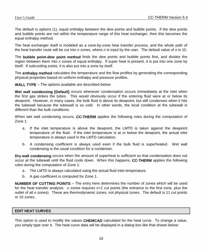
HEAT CURVE GENERATION
Selecting this option will cause the Heat Curve Parameters dialog box to appear:
This dialog box contains commands that allow you to enter the data necessary to calculate the heat curves for the exchanger. It is important to note that if you have made any changes to the streams or heat exchanger units within CHEMCAD, you will receive a warning from CC-THERM recommending that you recalculate the heat curve to reflect those changes.
HEAT CURVE INPUT
CUTTING METHOD – The heat curve may be set up in zones of:
1. Equal enthalpy between dew points and bubble points;
2. Equal enthalpy.
User’s Guide CC-THERM Version 5.4
16
The default is options (1), equal enthalpy between the dew points and bubble points. If the dew points and bubble points are not within the temperature range of this heat exchanger, then this becomes the equal enthalpy method.
The heat exchanger itself is modeled as a zone-by-zone heat transfer process, and the whole path of the heat transfer route will be cut into n zones, where n is input by the user. The default value of n is 10.
The bubble point-dew point method finds the dew points and bubble points first, and divides the region between them into x zones of equal enthalpy. If super heat is present, it is put into one zone by itself. If subcooling exists, it is also put into a zone by itself.
The enthalpy method calculates the temperature and the flow profiles by generating the corresponding physical properties based on uniform enthalpy and pressure profiles.
WALL TYPE – The options available are described below:
Wet wall condensing [Default] occurs whenever condensation occurs immediately at the inlet when the first gas strikes the tubes. This would obviously occur if the entering fluid were at or below its dewpoint. However, in many cases, the bulk fluid is above its dewpoint, but still condenses when it hits the tubewall because the tubewall is so cold. In other words, the local condition at the tubewall is different than the bulk conditions.
When wet wall condensing occurs, CC-THERM applies the following rules during the computation of Zone 1:
a. If the inlet temperature is above the dewpoint, the LMTD is taken against the dewpoint temperature of the fluid. If the inlet temperature is at or below the dewpoint, the actual inlet temperature is always used in the LMTD calculation.
b. A condensing coefficient is always used even if the bulk fluid is superheated. Wet wall condensing is the usual condition for a condenser.
Dry wall condensing occurs when the amount of superheat is sufficient so that condensation does not occur at the tubewall until the fluid cools down. When this happens, CC-THERM applies the following rules during the computation of Zone 1:
a. The LMTD is always calculated using the actual fluid inlet temperature. b. A gas coefficient is computed for Zone 1.
NUMBER OF CUTTING POINTS – The entry here determines the number of zones which will be used for the heat transfer analysis. n zones requires n+1 cut points (the entrance to the first zone, plus the outlet of all n zones). These are thermodynamic zones, not physical zones. The default is 11 cut points or 10 zones.
EDIT HEAT CURVES
This option is used to modify the values CHEMCAD calculated for the heat curve. To change a value, you simply type over it. The heat curve data will be displayed in a dialog box like that shown below:
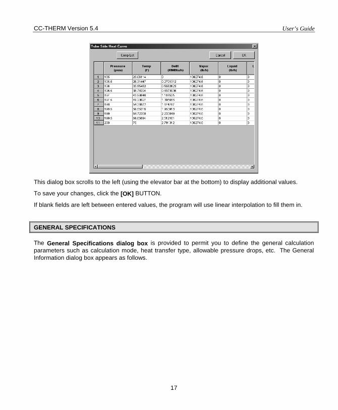
CC-THERM Version 5.4 User’s Guide
17
This dialog box scrolls to the left (using the elevator bar at the bottom) to display additional values.
To save your changes, click the [OK] BUTTON.
If blank fields are left between entered values, the program will use linear interpolation to fill them in.
GENERAL SPECIFICATIONS
The General Specifications dialog box is provided to permit you to define the general calculation parameters such as calculation mode, heat transfer type, allowable pressure drops, etc. The General Information dialog box appears as follows.
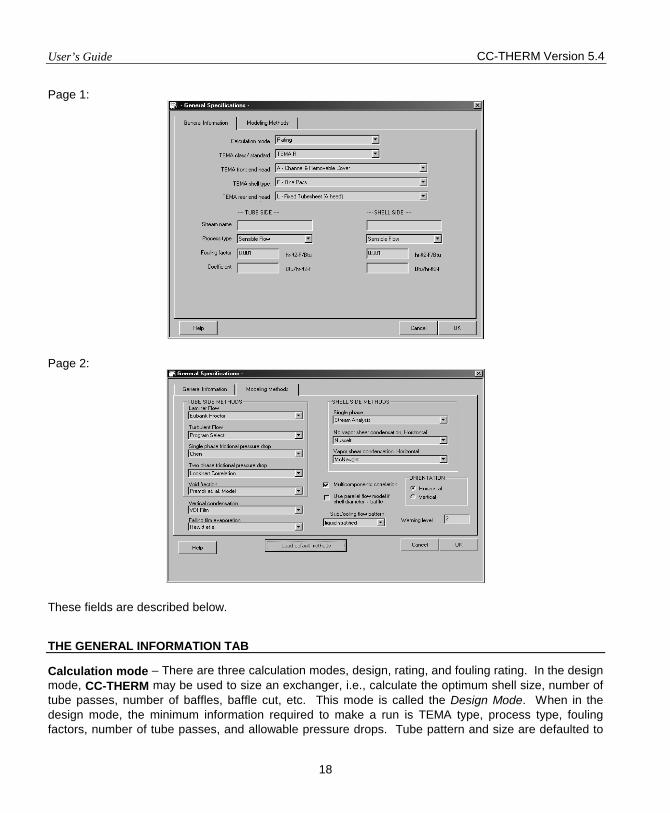
User’s Guide CC-THERM Version 5.4
18
Page 1:
Page 2:
These fields are described below.
THE GENERAL INFORMATION TAB
Calculation mode – There are three calculation modes, design, rating, and fouling rating. In the design mode, CC-THERM may be used to size an exchanger, i.e., calculate the optimum shell size, number of tube passes, number of baffles, baffle cut, etc. This mode is called the Design Mode. When in the design mode, the minimum information required to make a run is TEMA type, process type, fouling factors, number of tube passes, and allowable pressure drops. Tube pattern and size are defaulted to
CC-THERM Version 5.4 User’s Guide
19
triangular, ¾-inch, 16 BWG. Clearances are set to TEMA. Any variable, which you want to override and any information over and above the minimum may also be supplied. The program will hold these fixed while optimizing the remaining information. In the rating mode, area excess is calculated. In the fouling rating mode, tube and/or shell side fouling factors can be determined for given flow and exchanger geometry.
CC-THERM may also be used to rate an existing exchanger. In this mode, all the key variables must be defined. The program checks to see if the exchanger defined will work in the given application. You must define the TEMA type, process type, shell ID, number of tube passes, baffle spacing and cut and the number of tubes. Unless overridden, CC-THERM will default to ¾-inch, 16 BWG tubes and TEMA clearances.
Note: If you run an exchanger in Design mode, then switch to Rating mode, the program will automatically read in key data for the Exchanger menus. This only works directly after a run is performed; it will not work if you switch units, switch case studies, or exit the program between running the Design and switching to a Rating.
TEMA class - The class is in accordance with the Tubular Exchanger Manufacturer's Association (TEMA). When not running according to TEMA, other options are available. These standards refer mostly to the mechanical details of the exchanger. Consequently, the thermal design and analysis of the exchanger are not heavily influenced by this parameter.
The mechanical class (TEMA Class) affects the thermal calculation in two ways.
1. If affects the tube-sheet sizing calculation. CC-THERM will compute the approximate thickness of the tubesheet. This is necessary to determine the effective area for heat transfer. The portion of the tube covered by the tubesheet will not be available for heat transfer. The mechanical class specifies which rules are to be used to size the tubesheet.
2. The class will also determine what standard commercial sizes are available for various components of the exchanger. For instance, standard pipe shells would be different using TEMA (American) or DIN (German) standards. The pipe shell ID's would then affect the tube count and, thus, the area available for heat transfer.
TEMA R TEMA B TEMA C ASME DIN A.D. Merkblatter British Standard 5500
Non-standard TEMA front head - The following selections are available under this option. A = Channel and Removable Cover B = Bonnet C = Removable Bundle D = Special High Pressure Closure
User’s Guide CC-THERM Version 5.4
20
N = Channel with Tubesheet and Removable Cover
TEMA shell type - The following selection is available under this option. E = One Pass F = Two Pass G = Split Flow H = Double Split Flow J = Divided Flow K = Kettle Reboiler X = crossflow shell
TEMA rear head - The following selections are available under this option.
L = Fixed Tubesheet (A head) M = Fixed Tubesheet (B head) N = Fixed Tubesheet (N head) P = Outside Packed Flt Head S = Flt Head with Backing Device T = Pull Through Flt Head U = U-Tube Bundle W = Exit sealed Flt Tubesheet
Stream name – Optional stream names may be entered for the shell and tube sides of the heat exchanger. These names are only used for reporting purposes.
Process type - You must determine the process type on both the shell and tube sides. The process type specifies which heat transfer mechanism is to be used when calculating the film coefficients. For instance, while it is obvious that CC-THERM will know when there is evaporation on the tubeside, it will not know if that evaporation is forced, falling film, or thermosyphon. You must define which evaporation mechanism is to be used. The following process types are accommodated.
Tubeside Shellside Sensible flow Sensible flow Horizontal condensation Horizontal condensation Vertical condensation Vertical Condensation Knock-back condensation Forced Evaporation Forced evaporation Pool evaporation Falling film evaporation Horizontal thermosyphon Vertical thermosyphon
CC-THERM Version 5.4 User’s Guide
21
Fouling factor - Input of this variable is required. It is a thermal resistance included to account for the fouling. Its value is arbitrary and defines how often you want to clean the tubes. The default is 0.001 in English units on both sides.
Coefficient - Input of this variable is optional. If one wants to specify shell or tube side film heat transfer coefficient, he or she could enter the value in the corresponding field. The program will take this value in calculating the overall heat transfer coefficient. In case of zone-by-zone analysis, this value will be used in calculating the local overall heat transfer coefficient for each zone.
THE MODELING METHODS TAB
Tubeside Methods:
Laminar Flow– This option defines which equation is to be used to calculate the sensible heat transfer film coefficient for laminar flow on the tubeside. The options are:
Eubank-Proctor Reference S9 VDI–Mean Nusselt Number Reference S13
Turbulent Flow– This option specifies which method is to be used to calculate the tubeside film coefficient for sensible, turbulent flow on the tubeside, the options are:
Program Select: Let CC-THERM select the most appropriate method base upon the turbulent flow conditions.
Seader-Tate: Reference No. S1 Colburn Method: Reference No. S2 Dittus-Boelter: Reference No. S2 ESDU Method: Reference No. S17 Mean VDI Nusselt: Reference No. S18
Single Phase Frictional Pressure Drop - This identifies the method to be used to calculate the tubeside frictional pressure drop. The options are:
The Blasius Equation See Reference No. S15 Chen’s Method See Reference No. S16
Two Phase Frictional Pressure Drop - This options permits the user to select the method to be used to calculate the two-phase pressure drop. This method is used for both the tubeside and the shellside. The options are:
Lockhart-Martinell: See Reference No. C18 Friedal (CISE method): See Reference No. E6 and E8 Chisholm Method: See Reference No. C19
User’s Guide CC-THERM Version 5.4
22
Void Fraction - The void fraction model is used to calculate the two-phase flow void fraction for the calculation of two-phase pressure drop. The options are:
Premoli, et. al.: See Reference No. E17 Homogeneous Model: See Reference No. C19 Lockhart & Martinelli: See Reference No. E6 and E8
Vertical Condensation - The options are:
The Chemstations Method:
See Reference No. C24
The VDI Method: See Reference No. C25
Falling Film Evaporation - The options are:
Hewitt et. al.: See Reference No. E25 VDI: See Reference No. E26
Shellside Methods:
Single Phase - This option selects which method is to be used to calculate the shellside pressure drops and film coefficients for sensible flow. The options are:
Stream-analysis Method: Reference No. S4, S14, S15, S16 Bell-Delaware Method: Reference No. S3 Kern Method Reference No. S2
No Vapor Shear Condensation, Horizontal - The laminar condensation model is used to calculate the condensing film coefficient for laminar flow. The available options are:
The Kern’s Method: See Reference No. S2 The Nusselt: See Reference No. C20 The Eisenberg: See Reference No. C20
Vapor Shear Condensation, Horizontal - The turbulent condensation model is used to calculate the condensing film coefficient in turbulent flow. The available options are:
Nusselt: See Reference No. C20 The McNaught Method: See Reference No. C21 Taborek Method: See Reference No. C22
CC-THERM Version 5.4 User’s Guide
23
Multicomponent Correlation - Selecting this option applies the Silver-Bell-Ghaly procedure to the calculation of non-isothermal (i.e., multicomponent) condensation. The presence of the checkmark means that the SBG Method will be used. This is the default. References: C1, C2
Use Parallel Flow Model If Shell Diameter < Baffle Spacing – If this option is checked, the program will use parallel flow model for shell side computation when shell diameter is less than center baffle spacing. However, the crossing flow model is always used when shell diameter is greater than center baffle spacing. It is suggested to check this option if baffle spacing is far greater than shell diameter. Leave this option unchecked when running design.
Subcooling Flow Pattern – Choose from stratified or filled pipe liquid flow. This option applies only to condensers.
The liquid filled model assumes that after the bulk dew point is reached, the tube is completely filled with liquid. Therefore, in subcooling zones, the velocities and film coefficients are low. This is a very conservative method.
In the liquid stratified flow model local subcooling occurs before the bulk dew point is reached. Therefore, the flow is stratified even in the subcooling zones. The nature of the stratification depends on whether the exchanger is vertical or horizontal.
Orientation – Select from Horizontal or Vertical.
Warning level – Specify an integer between 0 and 3. Default is 2. The value controls suppression of warning messages during CC-THERM calculation.
0 all warning messages are suppressed
1 most warning messages are suppressed
2 few warning messages are suppressed
3 no warning messages are suppressed
THE DESIGN OPTIONS DIALOG BOX
If the design option is selected on the General Information dialog box, then when this dialog box is closed, the Design Options dialog box will appear. The purpose of this dialog box is to allow the user to constrain the sizing calculation to specified boundaries. The dialog box looks like this:
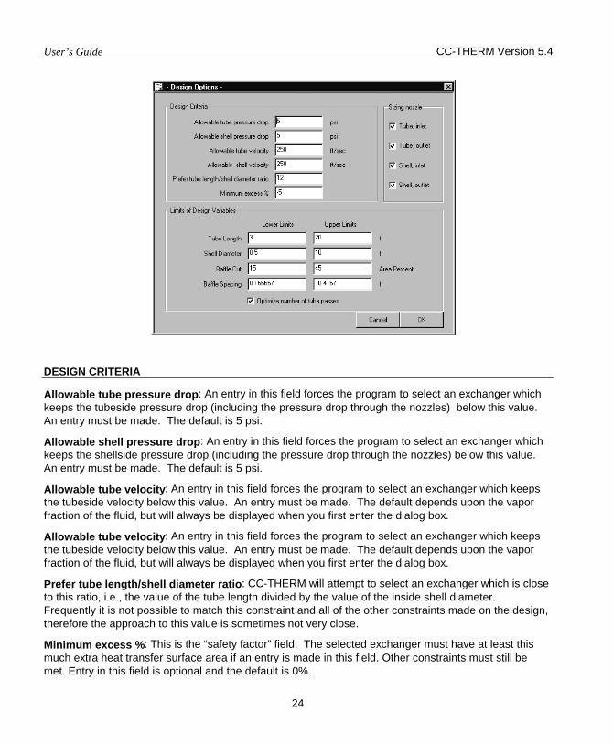
User’s Guide CC-THERM Version 5.4
24
DESIGN CRITERIA
Allowable tube pressure drop: An entry in this field forces the program to select an exchanger which keeps the tubeside pressure drop (including the pressure drop through the nozzles) below this value. An entry must be made. The default is 5 psi.
Allowable shell pressure drop: An entry in this field forces the program to select an exchanger which keeps the shellside pressure drop (including the pressure drop through the nozzles) below this value. An entry must be made. The default is 5 psi.
Allowable tube velocity: An entry in this field forces the program to select an exchanger which keeps the tubeside velocity below this value. An entry must be made. The default depends upon the vapor fraction of the fluid, but will always be displayed when you first enter the dialog box.
Allowable tube velocity: An entry in this field forces the program to select an exchanger which keeps the tubeside velocity below this value. An entry must be made. The default depends upon the vapor fraction of the fluid, but will always be displayed when you first enter the dialog box.
Prefer tube length/shell diameter ratio: CC-THERM will attempt to select an exchanger which is close to this ratio, i.e., the value of the tube length divided by the value of the inside shell diameter. Frequently it is not possible to match this constraint and all of the other constraints made on the design, therefore the approach to this value is sometimes not very close.
Minimum excess %: This is the “safety factor” field. The selected exchanger must have at least this much extra heat transfer surface area if an entry is made in this field. Other constraints must still be met. Entry in this field is optional and the default is 0%.
CC-THERM Version 5.4 User’s Guide
25
SIZING NOZZLES
If these fields are checked (default), then the program will size the nozzles during the design calculation. If these fields are blank, then the user must specify the nozzle sizes on the Nozzles dialog box, which is on the Exchanger Geometry Menu.
LIMITS OF DESIGN VARIABLES
These entries limit the allowable dimensions which the program can choose from when searching for an exchanger which will meet the design criteria. The program must stay between the lower and upper limits of each of the variables.
Tube Length: This is the installed tube length including that portion covered by the tubesheet(s). Therefore, not all of this length will be available for heat transfer.
Shell Diameter: This is the nominal diameter of the shell if a pipe shell is being used and the inside diameter of the shell if rolled plate is being used.
Baffle Cut: This specification is in percent and can be based on diameter (default) or area depending on what is specified on the Baffles dialog box on the Exchanger Geometry Menu.
Baffle Spacing: This is the distance between baffles. The unsupported tube length is twice this value.
Optimize number of passes:Check this option to have the program optimize the number of tube of passes when doing a design calculation for shell and tube heat exchangers.
THE THERMOSYPHON REBOILER DIALOG BOX
If your heat exchanger is a thermosyphon reboiler, then you may want the program to calculate the amount of fluid circulating through the syphon. This calculation requires knowledge of the inlet and outlet piping geometrices as well as of the available static head. The Thermosyphon Reboiler dialog box is designed to collect this information. It will open whenever you close the General Information dialog box only if you are designing or rating a thermosyphon.
The Thermosyphon Reboiler dialog box looks like this:
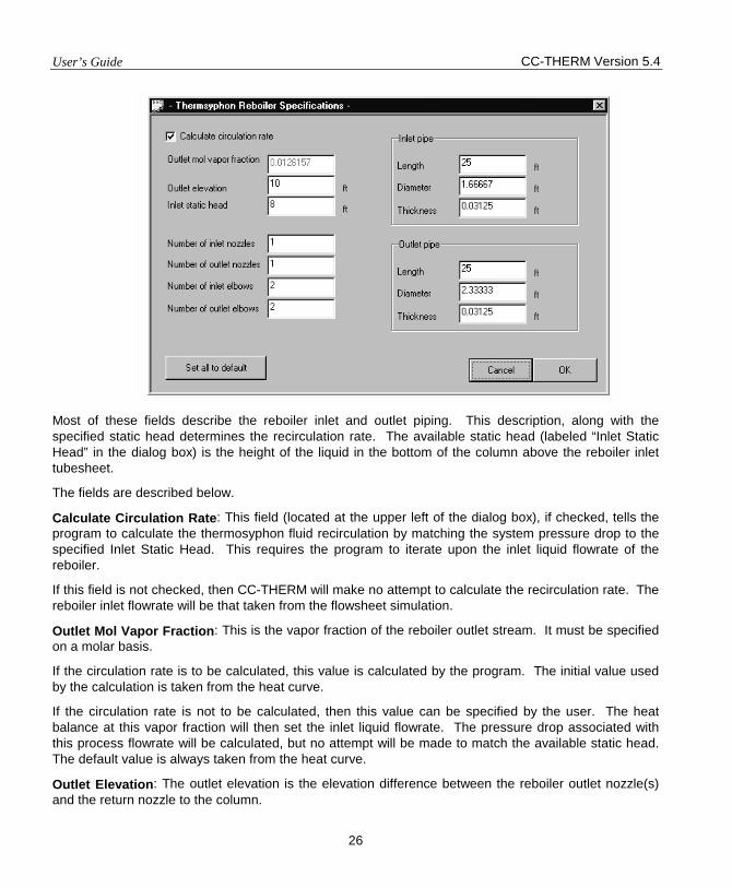
User’s Guide CC-THERM Version 5.4
26
Most of these fields describe the reboiler inlet and outlet piping. This description, along with the specified static head determines the recirculation rate. The available static head (labeled “Inlet Static Head” in the dialog box) is the height of the liquid in the bottom of the column above the reboiler inlet tubesheet.
The fields are described below.
Calculate Circulation Rate: This field (located at the upper left of the dialog box), if checked, tells the program to calculate the thermosyphon fluid recirculation by matching the system pressure drop to the specified Inlet Static Head. This requires the program to iterate upon the inlet liquid flowrate of the reboiler.
If this field is not checked, then CC-THERM will make no attempt to calculate the recirculation rate. The reboiler inlet flowrate will be that taken from the flowsheet simulation.
Outlet Mol Vapor Fraction: This is the vapor fraction of the reboiler outlet stream. It must be specified on a molar basis.
If the circulation rate is to be calculated, this value is calculated by the program. The initial value used by the calculation is taken from the heat curve.
If the circulation rate is not to be calculated, then this value can be specified by the user. The heat balance at this vapor fraction will then set the inlet liquid flowrate. The pressure drop associated with this process flowrate will be calculated, but no attempt will be made to match the available static head. The default value is always taken from the heat curve.
Outlet Elevation: The outlet elevation is the elevation difference between the reboiler outlet nozzle(s) and the return nozzle to the column.
CC-THERM Version 5.4 User’s Guide
27
Inlet Static Head: This is the elevation difference between the surface of the liquid in the bottom of the column and the “inlet” tubesheet closest to the inlet nozzle.
This value is specified in the height of process liquid. If the thermosyphon circulation rate is to be calculated by the program, then this field must be specified. For this reason, the program always provides some default. The circulation rate calculation will vary the reboiler inlet flowrate until the calculated pressure drop from the column outlet nozzle to the column return nozzle matches the specified inlet static head.
No. of Inlet Nozzles: This is the number of the inlet nozzles on the process side of the reboiler itself. If the thermosyphon is vertical, you will always want to use a one in this field. However, horizontal or shell side thermosyphons may have more than one inlet nozzle depending upon the TEMA shell type. CC-THERM will not automatically pick up this value, so if it is other than one, you will need to enter it. Multiple inlet nozzles affect the performance of the process side pressure drop calculation.
No. of Outlet Nozzles: This is the number of outlet nozzles on the process side of the reboilers itself. If the thermosyphon is vertical, this will almost always be one (the default). However, horizontal or shell-side thermosyphon may have more than one inlet nozzle depending on the TEMA shell type. CC-THERM will not automatically pick up this value, so if it is other than one, you will need to enter it. Multiple outlet nozzles affect the performance of the process side pressure drop calculation.
No. of Inlet Elbows: Specify the number of ninety degree turns in the piping going from the bottom of the column to the reboiler inlet nozzle(s). The default is two. The resistance for this number of standard, 900 elbows will be added to the inlet pipe length specified below when the pressure drop calculations are performed.
No. of Outlet Elbows: Specify the number of 900 turns in the outlet piping going from the reboiler outlet nozzle(s) to the column return nozzle. The default is one. The resistance for this number of 900 elbows will be added to the outlet pipe length specified below when the pressure drops are calculated.
Safety Factor: This value is only relevant if the circulation rate is not to be calculated. The safety factor is multiplied by the calculated pressure drop to arrive at the final pressure drop.
INLET PIPE
Length: Specify the length (or total equivalent length of all flow resistances) of the inlet pipe (from the column outlet nozzle to the reboiler inlet nozzle). The default value is 15 feet.
Diameter: Specify the inlet piping diameter. The default value is the rebolier inlet nozzle diameter if known. This is the outside diameter.
Thickness: Specify the wall thickness of the inlet piping.
OUTLET PIPE
Length: Specify the length (or total equivalent length of all flow resistance) of the outlet piping (from the reboiler outlet nozzle(s) to the column return nozzle). The default value is 10 feet.
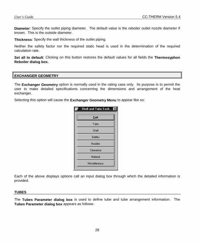
User’s Guide CC-THERM Version 5.4
28
Diameter: Specify the outlet piping diameter. The default value is the reboiler outlet nozzle diameter if known. This is the outside diameter.
Thickness: Specify the wall thickness of the outlet piping.
Neither the safety factor nor the required static head is used in the determination of the required calculation rate.
Set all to default: Clicking on this button restores the default values for all fields the Thermosyphon Reboiler dialog box.
EXCHANGER GEOMETRY
The Exchanger Geometry option is normally used in the rating case only. Its purpose is to permit the user to make detailed specifications concerning the dimensions and arrangement of the heat exchanger.
Selecting this option will cause the Exchanger Geometry Menu to appear like so:
Each of the above displays options call an input dialog box through which the detailed information is provided.
TUBES
The Tubes Parameter dialog box is used to define tube and tube arrangement information. The Tubes Parameter dialog box appears as follows:

CC-THERM Version 5.4 User’s Guide
29
These fields are described below.
Number of tubes - This field should only be used for a rating case, in which case its entry is mandatory. It may happen that you will input a given number of tubes which you know will fit in a given size shell, but the program refuses to run and returns the message that a larger shell size must be used. In this case, you should go to the Clearances dialog box and input the diametrical gap between the shell internal diameter and the bundle outer tube limit diameter. When this is done, the program will accept your tube count input. Care must be taken when this option is used since it is possible to force the program to accept an unrealistic situation. This field is not read for a design case.
Number of tube passes - The number of tube passes is mandatory for a rating case. For the full design case, it is recommended that you allow the program to optimize the number of tube passes. If you have a situation where there is a large temperature cross between the shellside and tubeside, thus forcing the need for counter-current flow, it is advisable to fix the number of passes to one (or two, if using an F shell). The program will tolerate an LMTD correction factor down to .5; below this value, the program will stop with an error message. At LMTD correction factors below 0.5, it is thermodynamically impossible to achieve the stated process conditioning.
Tube outer diameter - The tube diameter is an optional input. If no value is input, the program defaults to a diameter of ¾-inch (19.05-mm) outside diameter tubes.
Tube wall thickness - The wall thickness input is optional. If no value is input, the program defaults to BWG 16 (.065-inches or 1.65-mm).
Tube length - This field is a mandatory input for a rating case. For a design case, it is best to let the program optimize the tube length. When optimizing the tube length, the program starts with a minimum length of 6 feet (1.83 meters) for small exchangers (D = 6-inches, 160-mm) and gradually works up to a maximum length of 20 feet or 6.1 meters for shell sizes of 14-inches (350-mm) and above. If you need the program to try lengths over (or different from) 20 feet (6.1 meters) and yet not have to fix the length, you should use the Shell Parameters dialog box to specify multiple shells in series.
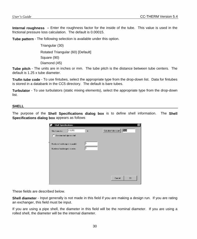
User’s Guide CC-THERM Version 5.4
30
Internal roughness – Enter the roughness factor for the inside of the tube. This value is used in the frictional pressure loss calculation. The default is 0.00015.
Tube pattern - The following selection is available under this option.
Triangular (30)
Rotated Triangular (60) [Default] Square (90) Diamond (45)
Tube pitch - The units are in inches or mm. The tube pitch is the distance between tube centers. The default is 1.25 x tube diameter.
Trufin tube code - To use fintubes, select the appropriate type from the drop-down list. Data for fintubes is stored in a databank in the CC5 directory. The default is bare tubes.
Turbulator - To use turbulators (static mixing elements), select the appropriate type from the drop-down list.
SHELL
The purpose of the Shell Specifications dialog box is to define shell information. The Shell Specifications dialog box appears as follows
These fields are described below.
Shell diameter - Input generally is not made in this field if you are making a design run. If you are rating an exchanger, this field must be input.
If you are using a pipe shell, the diameter in this field will be the nominal diameter. If you are using a rolled shell, the diameter will be the internal diameter.
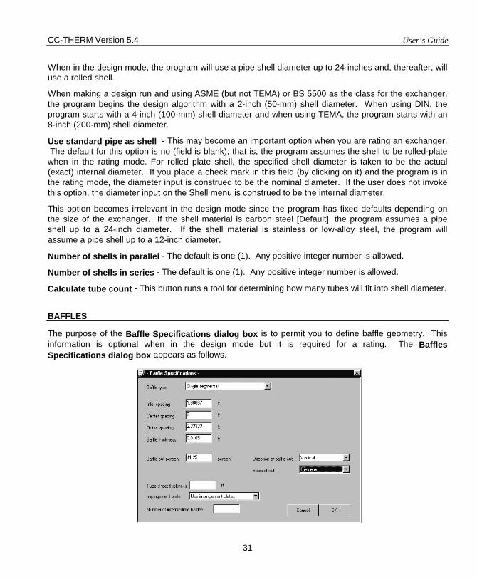
CC-THERM Version 5.4 User’s Guide
31
When in the design mode, the program will use a pipe shell diameter up to 24-inches and, thereafter, will use a rolled shell.
When making a design run and using ASME (but not TEMA) or BS 5500 as the class for the exchanger, the program begins the design algorithm with a 2-inch (50-mm) shell diameter. When using DIN, the program starts with a 4-inch (100-mm) shell diameter and when using TEMA, the program starts with an 8-inch (200-mm) shell diameter.
Use standard pipe as shell - This may become an important option when you are rating an exchanger. The default for this option is no (field is blank); that is, the program assumes the shell to be rolled-plate when in the rating mode. For rolled plate shell, the specified shell diameter is taken to be the actual (exact) internal diameter. If you place a check mark in this field (by clicking on it) and the program is in the rating mode, the diameter input is construed to be the nominal diameter. If the user does not invoke this option, the diameter input on the Shell menu is construed to be the internal diameter.
This option becomes irrelevant in the design mode since the program has fixed defaults depending on the size of the exchanger. If the shell material is carbon steel [Default], the program assumes a pipe shell up to a 24-inch diameter. If the shell material is stainless or low-alloy steel, the program will assume a pipe shell up to a 12-inch diameter.
Number of shells in parallel - The default is one (1). Any positive integer number is allowed.
Number of shells in series - The default is one (1). Any positive integer number is allowed.
Calculate tube count - This button runs a tool for determining how many tubes will fit into shell diameter.
BAFFLES
The purpose of the Baffle Specifications dialog box is to permit you to define baffle geometry. This information is optional when in the design mode but it is required for a rating. The Baffles Specifications dialog box appears as follows.

User’s Guide CC-THERM Version 5.4
32
These fields are described below.
Baffle type - Any of the following baffle configurations may be selected. Single segmental baffle (default) Double segmental baffle Triple segmental baffle No tubes in window Disk & Donut Rod
Single segmental baffle is the default. Generally speaking, the higher the baffle segmentation, the lower the shellside pressure drop and heat transfer coefficient. Double and triple segmental baffles lower velocities and therefore pressure drops and film coefficients as well.
No-tubes-in-window and rod baffles are used when high gas velocities on the shellside are producing vibration problems. Both effectively lower velocities while maintaining short tube spans, resulting in lower tube natural frequencies.
Inlet spacing This is the spacing between the front tubesheet and the first baffle. The program will calculate this spacing if left blank.
Center spacing This is a mandatory input if you are making a rating case. If making a design run, the program will optimize on this parameter.
Outlet spacing This is the spacing between the last baffle and the rear tubesheet. The program will calculate this value if left blank.
Baffle thickness The baffle thickness affects the effective area of the tube and the vibration analysis. The default is indicated.
Baffle cut percent The program assumes that the cut is a percent of the diameter. If the cut is based on area, you should indicate such in the field below. If the baffle is a rod baffle or a full circle type, then place a 0 in this field.
X Overlap This is the amount of overlap for double segmental and triple segmental baffles. X is the overlap distance. X-overlap field will appear only if you select double or triple segmental baffles.
Tubesheet thickness This is the thickness of the tubesheet.
Direction of baffle cut The following selections are available under this option: Vertical cut Horizontal cut [Default] Diagonal cut

CC-THERM Version 5.4 User’s Guide
33
Basis of cut The following selection is available under this option.
Diameter Area
Impingement plate Selecting "Let program decide" will allow the program to determine if an impingement plate is necessary using the rules of TEMA. Using Impingement Plate or No Impingement Plate will force the use or exclusion of an impingement plate.
When it is not practical to fit an impingement plate inside or outside a shell, a vapor belt could be used to reduce entrance momentum of high speed vapor at inlet nozzle. CCTHERM allows use of box type vapor belt as impingement device. One may refer to the figure 9 on page 4.2.5-8 of HEDH. Three input variables are Belt diameter, Port hole diameter, and Belt width. Belt diameter should be specified larger than shell diameter, otherwise a value of shell diameter plus half of nozzle diameter will be used. Port hole diameter is the diameter of the hole on the shell continuous through which vapor enters the shell. If more than one hole or non round hole is used, an area equivalent diameter may be specified. If not specified, the value of nozzle diameter will be used for the port hole diameter. Belt width should be specified greater than nozzle diameter, other wise a value twice of nozzle diameter will be used for the width in the calculation of vapor belt pressure drop.
Number of intermediate Baffles You should input the number of intermediate baffles to be used when using No Tubes-in-Windows baffles. Vibration problems on the exchanger shellside warrant the use of intermediate baffles so as to shorten the unsupported tube length and thus increase the natural frequency of the tube bundle.
NOZZLES
The purpose of the Nozzles Specifications dialog box is to permit you to specify nozzle sizes or information to be used by the program in sizing the nozzles. In the default condition, CC-THERM will size the nozzles whether you are in the design or rating mode. In the sizing calculation, the program will attempt to take 25% of the specified allowable pressure drop across the nozzles unless velocity limits are exceeded; in which case it will take less. The Nozzles Specifications dialog box appears as follows.

User’s Guide CC-THERM Version 5.4
34
These fields are described below.
Nozzle diameter - This diameter is the nominal diameter in all cases. Even if making a rating, it is not obligatory to input the nozzle diameter, as the program will calculate them if this information is omitted.
Longneck - If the nozzles are to be longneck, enter a check mark in this field by clicking on it. The default is no.
Orientation - This is the orientation of the shellside nozzles. The options are:
Opposite side Same side
The default for this field is to have the nozzles placed on the opposite side of the exchanger. If you want to have them located on the same side, the user should select same side. This will effect the baffle count for a single segmental baffle. With same side, the baffle count will be even; with opposite side, the baffle count will be odd.
The default for a J-shell is one (1) inlet and two (2) outlets. You may reverse this setup by selecting opposite side.
Tubeside flow enters
• Bottom nozzle • Top nozzle
CLEARANCES
The Clearances dialog box permits you to specify the machining tolerances of the exchanger. Clearances can have a significant influence on the tube count as well as the shellside heat transfer and pressure drop.
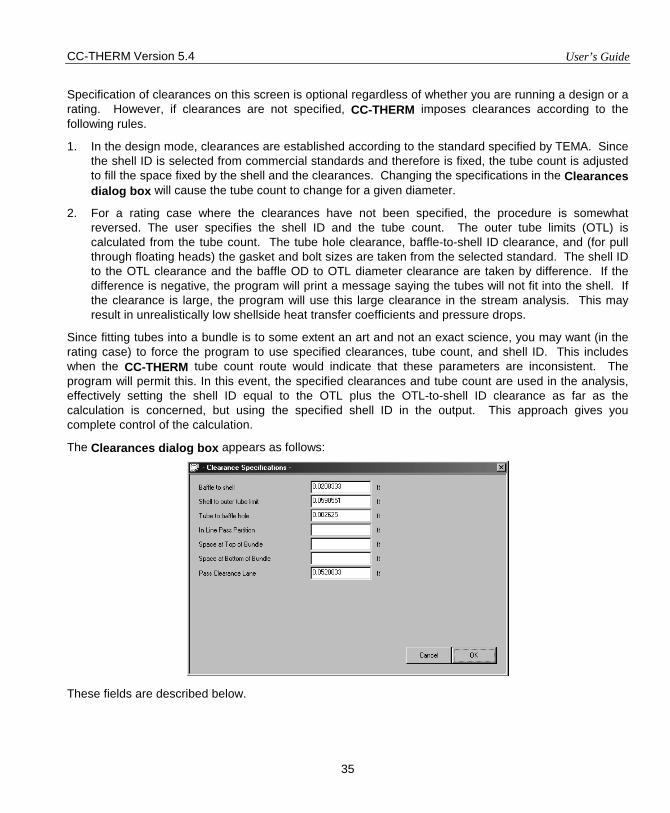
CC-THERM Version 5.4 User’s Guide
35
Specification of clearances on this screen is optional regardless of whether you are running a design or a rating. However, if clearances are not specified, CC-THERM imposes clearances according to the following rules.
1. In the design mode, clearances are established according to the standard specified by TEMA. Since the shell ID is selected from commercial standards and therefore is fixed, the tube count is adjusted to fill the space fixed by the shell and the clearances. Changing the specifications in the Clearances dialog box will cause the tube count to change for a given diameter.
2. For a rating case where the clearances have not been specified, the procedure is somewhat reversed. The user specifies the shell ID and the tube count. The outer tube limits (OTL) is calculated from the tube count. The tube hole clearance, baffle-to-shell ID clearance, and (for pull through floating heads) the gasket and bolt sizes are taken from the selected standard. The shell ID to the OTL clearance and the baffle OD to OTL diameter clearance are taken by difference. If the difference is negative, the program will print a message saying the tubes will not fit into the shell. If the clearance is large, the program will use this large clearance in the stream analysis. This may result in unrealistically low shellside heat transfer coefficients and pressure drops.
Since fitting tubes into a bundle is to some extent an art and not an exact science, you may want (in the rating case) to force the program to use specified clearances, tube count, and shell ID. This includes when the CC-THERM tube count route would indicate that these parameters are inconsistent. The program will permit this. In this event, the specified clearances and tube count are used in the analysis, effectively setting the shell ID equal to the OTL plus the OTL-to-shell ID clearance as far as the calculation is concerned, but using the specified shell ID in the output. This approach gives you complete control of the calculation.
The Clearances dialog box appears as follows:
These fields are described below.
User’s Guide CC-THERM Version 5.4
36
Baffle to shell - This is the gap between the inside wall of the shell and the baffle. This gap is defined on a diametrical basis. Therefore, if the actual gap between the baffle and the shell ID is 0.25-inches, the entry in this field should be 0.5-inches since there are two gaps along the diameter, one at each end.
This entry would only be used if you do not accept the program default for this option.
Shell ID to bundle outer tube limit - The default for this option is the TEMA Standard clearance and you should also refer to the Number of Tubes in the Tube menu. When this entry is input and a rating case is being made, the program will accept any tube count, which the user inputs. Therefore, greater care must be taken when this field is input. This option was purposely programmed in a fashion to circumvent any problems the user might have when making a rating case and the program finds that the tubes do not fit and yet the user is analyzing an existing exchanger and hence knows the tube count to be correct.
Tube to baffle hole - This is a diametrical gap. This entry would only be used if the user did not accept the program default of this option.
In-line pass partition – This is the space between the tubeset and the partition. The in-line pass partition size may have a significant effect upon the amount of vapor or liquid that bypasses the regular S-shaped flow pattern on the shell side of the exchanger. The fluid that is bypassed follows a more linear path through the shell.
Space at top of bundle - This space is measured from the outside diameter of the top row of tubes to the horizontal line described by the intersection of the shell with the shell nozzle horizontal line located at the top of the shell. A space of this nature is usually necessary if an impingement plate is present, and it is located on the bundle (it could also be located inside the shell nozzle). If the program is used in the design mode and an impingement plate is necessary the program will automatically calculate this space to meet the requirements of TEMA. It will also keep this space to the minimum necessary to allow the maximum number of tubes to fit in the given shell diameter. When using this option, you should be aware that if too small a value is placed here, it may provoke a disproportionately high pressure drop in the shell inlet nozzle and this could effect the program's convergence characteristics. Also, if you have No-Tubes-in-Window type baffles, a space similar to the one described herein will exist between the bundle and the shell. It is not necessary (and you should not use this option) to specify this void space for such a situation unless the void space necessary for placing the impingement plate is greater than the void space of the baffle cut of the No-Tubes-in-Window baffle.
Space at bottom of bundle - This space is measured from the outside diameter of the bottom row of tubes to the horizontal line described by the intersection of the shell with the shell nozzle located at the bottom of the shell. It may be necessary to use such a space, for example, when there is a sparger pipe located at the bottom of a kettle reboiler. In this case, a few rows of tubes would have to be eliminated from the bottom of the bundle and hence a void space would exist there. Again, as noted above, this option should not be used for the case of No-Tubes-in-Window type baffles unless the void space of the bundle is greater than the baffle cut.
Pass clearance lane - The units are inches or mm. The pass clearance lane is calculated according to the TEMA-recommended dimensions of the pass partition plate and whether the tubes are welded or expanded to the tubesheet. The pass clearance lane may have a significant effect on the heat transfer calculations on the shellside of the exchanger depending on the direction of the baffle cut and the tube pass arrangement.

CC-THERM Version 5.4 User’s Guide
37
MATERIALS
The Materials dialog box is used to specify the materials of construction. It is shown below.
You may specify the material type for each of the five exchanger components. This is accomplished by selecting one component's arrow box, which will bring up a scroll box containing the types of material available. Select the type using the mouse or arrow keys.
You may also input tube material density.
MISCELLANEOUS
The purpose of this dialog box is to permit the user to define a variety of parameters, which do not fit neatly into the other categories. The Miscellaneous dialog box appears as follows.
These fields are described below.
Rows/sealing strip - A sealing strip is a longitudinal, metal strip placed in the gap between the outer tube limit and the shell inside diameter in order to block bypass flow on the shell-side. If the user wishes
User’s Guide CC-THERM Version 5.4
38
to utilize sealing strips, you should do so here by indicating the number of rows at which sealing strips will be placed. For instance, if it will be every four rows, the number here would be 4. If the user is designing an exchanger with liquid or gas on the shell side and the rear head is TEMA type S or T, the program will automatically place sealing strips every 5 rows unless overridden by a number in this field.
Entrainment ratio - If you have a pool evaporator, you can specify the maximum amount ratio of entrained liquid in the vapor stream, and he/she would do so with this option. The program default is 2%. If the user places a small value (say 1%), the disengagement space will become proportionately greater, and, hence, the kettle diameter would become bigger. The kettle size may be fixed with the option listed under the Shells Parameter dialog box (if used, this option would become irrelevant).
Heat duty - The program always calculates and balances the heat loads on both the shell-side and the tube-side of the exchanger. If the user wants the output to appear with a rounded-up value of the calculated heat duty or simply wishes to design the heat exchanger for some excess heat load capacity, he/she may do so with this option.
U-bend efficiency (%) - If the user has a U-tube exchanger and he/she wishes to include some or all of the U portion of the tube as being effective for heat transfer, he/she may do so with this option. If the number 100 is input, this indicates that the entire U portion is effective in heat transfer and its surface will be included in the overall surface area. The default for this option is 0% or, in other words, none of the U-bend surface will be included in the overall heat transfer surface area.
U-bend radius - The default radius for the inner row of a U-tube bundle is 1.5 x the tube diameter. If the user wishes to use a different value, he/she may enter that value here.
Tube axial stress - If vibration problems are a major concern, this may become an important option to use as it may have an important effect on the tube bundle natural frequency. This is especially true if the tube stress is a compressive one, as this will lower the bundle natural frequency and very possibly exacerbate any vibration problems. If the stress is input with a negative sign, it is considered to be a compressive stress; otherwise, it will be considered to be a tensile stress.
CALCULATE
The Calculate command tells the program to execute the design or rating calculation. To begin the calculation, move the pointer to the Calculate option and click the left mouse button. After the command is issued, the program performs a complete data check to make sure there is no missing or unreasonable information. If errors or warnings are detected, the program shows an error message on the screen. The program allows you to either change the data or ignore the error messages.
In the design mode, the progress of the calculation will be reported in the lower left corner.
VIEW RESULTS
The View Results option enables the user to interactively review selected results on the screen. When selected, the VIEW MENU appears on the screen like so:
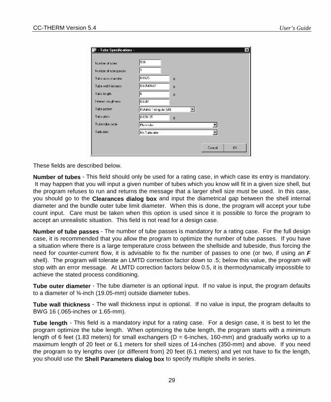
CC-THERM Version 5.4 User’s Guide
29
These fields are described below.
Number of tubes - This field should only be used for a rating case, in which case its entry is mandatory. It may happen that you will input a given number of tubes which you know will fit in a given size shell, but the program refuses to run and returns the message that a larger shell size must be used. In this case, you should go to the Clearances dialog box and input the diametrical gap between the shell internal diameter and the bundle outer tube limit diameter. When this is done, the program will accept your tube count input. Care must be taken when this option is used since it is possible to force the program to accept an unrealistic situation. This field is not read for a design case.
Number of tube passes - The number of tube passes is mandatory for a rating case. For the full design case, it is recommended that you allow the program to optimize the number of tube passes. If you have a situation where there is a large temperature cross between the shellside and tubeside, thus forcing the need for counter-current flow, it is advisable to fix the number of passes to one (or two, if using an F shell). The program will tolerate an LMTD correction factor down to .5; below this value, the program will stop with an error message. At LMTD correction factors below 0.5, it is thermodynamically impossible to achieve the stated process conditioning.
Tube outer diameter - The tube diameter is an optional input. If no value is input, the program defaults to a diameter of ¾-inch (19.05-mm) outside diameter tubes.
Tube wall thickness - The wall thickness input is optional. If no value is input, the program defaults to BWG 16 (.065-inches or 1.65-mm).
Tube length - This field is a mandatory input for a rating case. For a design case, it is best to let the program optimize the tube length. When optimizing the tube length, the program starts with a minimum length of 6 feet (1.83 meters) for small exchangers (D = 6-inches, 160-mm) and gradually works up to a maximum length of 20 feet or 6.1 meters for shell sizes of 14-inches (350-mm) and above. If you need the program to try lengths over (or different from) 20 feet (6.1 meters) and yet not have to fix the length, you should use the Shell Parameters dialog box to specify multiple shells in series.

CC-THERM Version 5.4 User’s Guide
31
When in the design mode, the program will use a pipe shell diameter up to 24-inches and, thereafter, will use a rolled shell.
When making a design run and using ASME (but not TEMA) or BS 5500 as the class for the exchanger, the program begins the design algorithm with a 2-inch (50-mm) shell diameter. When using DIN, the program starts with a 4-inch (100-mm) shell diameter and when using TEMA, the program starts with an 8-inch (200-mm) shell diameter.
Use standard pipe as shell - This may become an important option when you are rating an exchanger. The default for this option is no (field is blank); that is, the program assumes the shell to be rolled-plate when in the rating mode. For rolled plate shell, the specified shell diameter is taken to be the actual (exact) internal diameter. If you place a check mark in this field (by clicking on it) and the program is in the rating mode, the diameter input is construed to be the nominal diameter. If the user does not invoke this option, the diameter input on the Shell menu is construed to be the internal diameter.
This option becomes irrelevant in the design mode since the program has fixed defaults depending on the size of the exchanger. If the shell material is carbon steel [Default], the program assumes a pipe shell up to a 24-inch diameter. If the shell material is stainless or low-alloy steel, the program will assume a pipe shell up to a 12-inch diameter.
Number of shells in parallel - The default is one (1). Any positive integer number is allowed.
Number of shells in series - The default is one (1). Any positive integer number is allowed.
Calculate tube count - This button runs a tool for determining how many tubes will fit into shell diameter.
BAFFLES
The purpose of the Baffle Specifications dialog box is to permit you to define baffle geometry. This information is optional when in the design mode but it is required for a rating. The Baffles Specifications dialog box appears as follows.
User’s Guide CC-THERM Version 5.4
32
These fields are described below.
Baffle type - Any of the following baffle configurations may be selected. Single segmental baffle (default) Double segmental baffle Triple segmental baffle No tubes in window Disk & Donut Rod
Single segmental baffle is the default. Generally speaking, the higher the baffle segmentation, the lower the shellside pressure drop and heat transfer coefficient. Double and triple segmental baffles lower velocities and therefore pressure drops and film coefficients as well.
No-tubes-in-window and rod baffles are used when high gas velocities on the shellside are producing vibration problems. Both effectively lower velocities while maintaining short tube spans, resulting in lower tube natural frequencies.
Inlet spacing This is the spacing between the front tubesheet and the first baffle. The program will calculate this spacing if left blank.
Center spacing This is a mandatory input if you are making a rating case. If making a design run, the program will optimize on this parameter.
Outlet spacing This is the spacing between the last baffle and the rear tubesheet. The program will calculate this value if left blank.
Baffle thickness The baffle thickness affects the effective area of the tube and the vibration analysis. The default is indicated.
Baffle cut percent The program assumes that the cut is a percent of the diameter. If the cut is based on area, you should indicate such in the field below. If the baffle is a rod baffle or a full circle type, then place a 0 in this field.
X Overlap This is the amount of overlap for double segmental and triple segmental baffles. X is the overlap distance. X-overlap field will appear only if you select double or triple segmental baffles.
Tubesheet thickness This is the thickness of the tubesheet.
Direction of baffle cut The following selections are available under this option: Vertical cut Horizontal cut [Default] Diagonal cut
CC-THERM Version 5.4 User’s Guide
33
Basis of cut The following selection is available under this option.
Diameter Area
Impingement plate Selecting "Let program decide" will allow the program to determine if an impingement plate is necessary using the rules of TEMA. Using Impingement Plate or No Impingement Plate will force the use or exclusion of an impingement plate.
When it is not practical to fit an impingement plate inside or outside a shell, a vapor belt could be used to reduce entrance momentum of high speed vapor at inlet nozzle. CCTHERM allows use of box type vapor belt as impingement device. One may refer to the figure 9 on page 4.2.5-8 of HEDH. Three input variables are Belt diameter, Port hole diameter, and Belt width. Belt diameter should be specified larger than shell diameter, otherwise a value of shell diameter plus half of nozzle diameter will be used. Port hole diameter is the diameter of the hole on the shell continuous through which vapor enters the shell. If more than one hole or non round hole is used, an area equivalent diameter may be specified. If not specified, the value of nozzle diameter will be used for the port hole diameter. Belt width should be specified greater than nozzle diameter, other wise a value twice of nozzle diameter will be used for the width in the calculation of vapor belt pressure drop.
Number of intermediate Baffles You should input the number of intermediate baffles to be used when using No Tubes-in-Windows baffles. Vibration problems on the exchanger shellside warrant the use of intermediate baffles so as to shorten the unsupported tube length and thus increase the natural frequency of the tube bundle.
NOZZLES
The purpose of the Nozzles Specifications dialog box is to permit you to specify nozzle sizes or information to be used by the program in sizing the nozzles. In the default condition, CC-THERM will size the nozzles whether you are in the design or rating mode. In the sizing calculation, the program will attempt to take 25% of the specified allowable pressure drop across the nozzles unless velocity limits are exceeded; in which case it will take less. The Nozzles Specifications dialog box appears as follows.
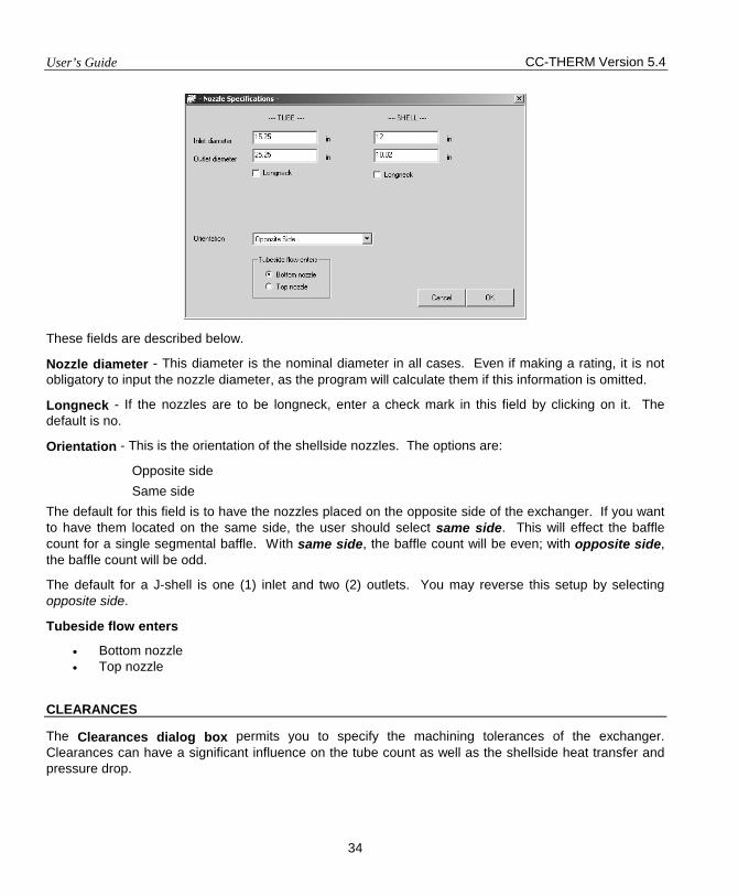
User’s Guide CC-THERM Version 5.4
34
These fields are described below.
Nozzle diameter - This diameter is the nominal diameter in all cases. Even if making a rating, it is not obligatory to input the nozzle diameter, as the program will calculate them if this information is omitted.
Longneck - If the nozzles are to be longneck, enter a check mark in this field by clicking on it. The default is no.
Orientation - This is the orientation of the shellside nozzles. The options are:
Opposite side Same side
The default for this field is to have the nozzles placed on the opposite side of the exchanger. If you want to have them located on the same side, the user should select same side. This will effect the baffle count for a single segmental baffle. With same side, the baffle count will be even; with opposite side, the baffle count will be odd.
The default for a J-shell is one (1) inlet and two (2) outlets. You may reverse this setup by selecting opposite side.
Tubeside flow enters
• Bottom nozzle • Top nozzle
CLEARANCES
The Clearances dialog box permits you to specify the machining tolerances of the exchanger. Clearances can have a significant influence on the tube count as well as the shellside heat transfer and pressure drop.

CC-THERM Version 5.4 User’s Guide
35
Specification of clearances on this screen is optional regardless of whether you are running a design or a rating. However, if clearances are not specified, CC-THERM imposes clearances according to the following rules.
1. In the design mode, clearances are established according to the standard specified by TEMA. Since the shell ID is selected from commercial standards and therefore is fixed, the tube count is adjusted to fill the space fixed by the shell and the clearances. Changing the specifications in the Clearances dialog box will cause the tube count to change for a given diameter.
2. For a rating case where the clearances have not been specified, the procedure is somewhat reversed. The user specifies the shell ID and the tube count. The outer tube limits (OTL) is calculated from the tube count. The tube hole clearance, baffle-to-shell ID clearance, and (for pull through floating heads) the gasket and bolt sizes are taken from the selected standard. The shell ID to the OTL clearance and the baffle OD to OTL diameter clearance are taken by difference. If the difference is negative, the program will print a message saying the tubes will not fit into the shell. If the clearance is large, the program will use this large clearance in the stream analysis. This may result in unrealistically low shellside heat transfer coefficients and pressure drops.
Since fitting tubes into a bundle is to some extent an art and not an exact science, you may want (in the rating case) to force the program to use specified clearances, tube count, and shell ID. This includes when the CC-THERM tube count route would indicate that these parameters are inconsistent. The program will permit this. In this event, the specified clearances and tube count are used in the analysis, effectively setting the shell ID equal to the OTL plus the OTL-to-shell ID clearance as far as the calculation is concerned, but using the specified shell ID in the output. This approach gives you complete control of the calculation.
The Clearances dialog box appears as follows:
These fields are described below.

User’s Guide CC-THERM Version 5.4
36
Baffle to shell - This is the gap between the inside wall of the shell and the baffle. This gap is defined on a diametrical basis. Therefore, if the actual gap between the baffle and the shell ID is 0.25-inches, the entry in this field should be 0.5-inches since there are two gaps along the diameter, one at each end.
This entry would only be used if you do not accept the program default for this option.
Shell ID to bundle outer tube limit - The default for this option is the TEMA Standard clearance and you should also refer to the Number of Tubes in the Tube menu. When this entry is input and a rating case is being made, the program will accept any tube count, which the user inputs. Therefore, greater care must be taken when this field is input. This option was purposely programmed in a fashion to circumvent any problems the user might have when making a rating case and the program finds that the tubes do not fit and yet the user is analyzing an existing exchanger and hence knows the tube count to be correct.
Tube to baffle hole - This is a diametrical gap. This entry would only be used if the user did not accept the program default of this option.
In-line pass partition – This is the space between the tubeset and the partition. The in-line pass partition size may have a significant effect upon the amount of vapor or liquid that bypasses the regular S-shaped flow pattern on the shell side of the exchanger. The fluid that is bypassed follows a more linear path through the shell.
Space at top of bundle - This space is measured from the outside diameter of the top row of tubes to the horizontal line described by the intersection of the shell with the shell nozzle horizontal line located at the top of the shell. A space of this nature is usually necessary if an impingement plate is present, and it is located on the bundle (it could also be located inside the shell nozzle). If the program is used in the design mode and an impingement plate is necessary the program will automatically calculate this space to meet the requirements of TEMA. It will also keep this space to the minimum necessary to allow the maximum number of tubes to fit in the given shell diameter. When using this option, you should be aware that if too small a value is placed here, it may provoke a disproportionately high pressure drop in the shell inlet nozzle and this could effect the program's convergence characteristics. Also, if you have No-Tubes-in-Window type baffles, a space similar to the one described herein will exist between the bundle and the shell. It is not necessary (and you should not use this option) to specify this void space for such a situation unless the void space necessary for placing the impingement plate is greater than the void space of the baffle cut of the No-Tubes-in-Window baffle.
Space at bottom of bundle - This space is measured from the outside diameter of the bottom row of tubes to the horizontal line described by the intersection of the shell with the shell nozzle located at the bottom of the shell. It may be necessary to use such a space, for example, when there is a sparger pipe located at the bottom of a kettle reboiler. In this case, a few rows of tubes would have to be eliminated from the bottom of the bundle and hence a void space would exist there. Again, as noted above, this option should not be used for the case of No-Tubes-in-Window type baffles unless the void space of the bundle is greater than the baffle cut.
Pass clearance lane - The units are inches or mm. The pass clearance lane is calculated according to the TEMA-recommended dimensions of the pass partition plate and whether the tubes are welded or expanded to the tubesheet. The pass clearance lane may have a significant effect on the heat transfer calculations on the shellside of the exchanger depending on the direction of the baffle cut and the tube pass arrangement.
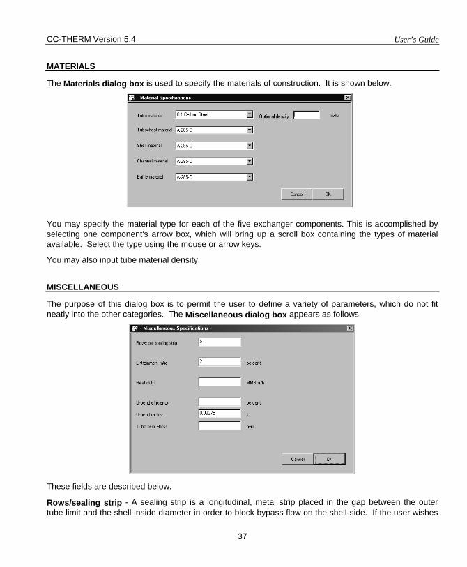
CC-THERM Version 5.4 User’s Guide
37
MATERIALS
The Materials dialog box is used to specify the materials of construction. It is shown below.
You may specify the material type for each of the five exchanger components. This is accomplished by selecting one component's arrow box, which will bring up a scroll box containing the types of material available. Select the type using the mouse or arrow keys.
You may also input tube material density.
MISCELLANEOUS
The purpose of this dialog box is to permit the user to define a variety of parameters, which do not fit neatly into the other categories. The Miscellaneous dialog box appears as follows.
These fields are described below.
Rows/sealing strip - A sealing strip is a longitudinal, metal strip placed in the gap between the outer tube limit and the shell inside diameter in order to block bypass flow on the shell-side. If the user wishes

User’s Guide CC-THERM Version 5.4
38
to utilize sealing strips, you should do so here by indicating the number of rows at which sealing strips will be placed. For instance, if it will be every four rows, the number here would be 4. If the user is designing an exchanger with liquid or gas on the shell side and the rear head is TEMA type S or T, the program will automatically place sealing strips every 5 rows unless overridden by a number in this field.
Entrainment ratio - If you have a pool evaporator, you can specify the maximum amount ratio of entrained liquid in the vapor stream, and he/she would do so with this option. The program default is 2%. If the user places a small value (say 1%), the disengagement space will become proportionately greater, and, hence, the kettle diameter would become bigger. The kettle size may be fixed with the option listed under the Shells Parameter dialog box (if used, this option would become irrelevant).
Heat duty - The program always calculates and balances the heat loads on both the shell-side and the tube-side of the exchanger. If the user wants the output to appear with a rounded-up value of the calculated heat duty or simply wishes to design the heat exchanger for some excess heat load capacity, he/she may do so with this option.
U-bend efficiency (%) - If the user has a U-tube exchanger and he/she wishes to include some or all of the U portion of the tube as being effective for heat transfer, he/she may do so with this option. If the number 100 is input, this indicates that the entire U portion is effective in heat transfer and its surface will be included in the overall surface area. The default for this option is 0% or, in other words, none of the U-bend surface will be included in the overall heat transfer surface area.
U-bend radius - The default radius for the inner row of a U-tube bundle is 1.5 x the tube diameter. If the user wishes to use a different value, he/she may enter that value here.
Tube axial stress - If vibration problems are a major concern, this may become an important option to use as it may have an important effect on the tube bundle natural frequency. This is especially true if the tube stress is a compressive one, as this will lower the bundle natural frequency and very possibly exacerbate any vibration problems. If the stress is input with a negative sign, it is considered to be a compressive stress; otherwise, it will be considered to be a tensile stress.
CALCULATE
The Calculate command tells the program to execute the design or rating calculation. To begin the calculation, move the pointer to the Calculate option and click the left mouse button. After the command is issued, the program performs a complete data check to make sure there is no missing or unreasonable information. If errors or warnings are detected, the program shows an error message on the screen. The program allows you to either change the data or ignore the error messages.
In the design mode, the progress of the calculation will be reported in the lower left corner.
VIEW RESULTS
The View Results option enables the user to interactively review selected results on the screen. When selected, the VIEW MENU appears on the screen like so:
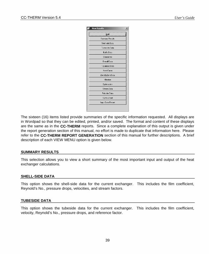
CC-THERM Version 5.4 User’s Guide
39
The sixteen (16) items listed provide summaries of the specific information requested. All displays are in Wordpad so that they can be edited, printed, and/or saved. The format and content of these displays are the same as in the CC-THERM reports. Since a complete explanation of this output is given under the report generation section of this manual, no effort is made to duplicate that information here. Please refer to the CC-THERM REPORT GENERATION section of this manual for further descriptions. A brief description of each VIEW MENU option is given below.
SUMMARY RESULTS
This selection allows you to view a short summary of the most important input and output of the heat exchanger calculations.
SHELL-SIDE DATA
This option shows the shell-side data for the current exchanger. This includes the film coefficient, Reynold’s No., pressure drops, velocities, and stream factors.
TUBESIDE DATA
This option shows the tubeside data for the current exchanger. This includes the film coefficient, velocity, Reynold’s No., pressure drops, and reference factor.
User’s Guide CC-THERM Version 5.4
40
BAFFLE DATA
This option displays a summary of the current baffle specifications (input).
CLEARANCE DATA
This option displays a summary of the current heat exchanger clearances being used by the program (input).
OVERALL DATA
This option displays a summary of the duty, area(s), heat transfer coefficient(s), and LMTD(s) of the heat exchanger.
TABULATED DATA
This option displays the Shell-side Data, Tubeside Data, Clearance Data, Baffle Data, Tabulated pressure drop distribution and Overall Data summaries together on one page.
HEAT CURVES
This displays the temperatures, vapor and liquid rates, heat duties, and physical and transport properties for each zone. These are the values used in the heat transfer and pressure drop calculations.
ZONE-BY-ZONE DATA
This option allows the user to review the zone-by-zone calculated results for both the tubeside and the shell-side.
VIBRATION
This displays the vibration analysis performed by CC-THERM. Results displayed include the natural frequency, the turbulent buffeting frequency, the vortex shedding frequency, and the acoustical frequency of the tube, as well as the critical ratios of these numbers.
OPTIMIZATION
This shows the optimization sequence used by CC-THERM.
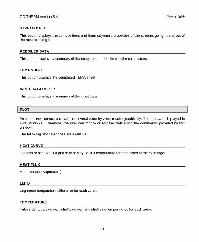
CC-THERM Version 5.4 User’s Guide
41
STREAM DATA
This option displays the compositions and thermodynamic properties of the streams going in and out of the heat exchanger.
REBOILER DATA
This option displays a summary of thermosyphon and kettle reboiler calculations.
TEMA SHEET
This option displays the completed TEMA sheet.
INPUT DATA REPORT
This option displays a summary of the input data.
PLOT
From the Plot Menu, you can plot several zone-by-zone results graphically. The plots are displayed in Plot Windows. Therefore, the user can modify or edit the plots using the commands provided by this window.
The following plot categories are available:
HEAT CURVE
Process heat curve is a plot of heat duty versus temperature for both sides of the exchanger.
HEAT FLUX
Heat flux (for evaporators)
LMTD
Log-mean temperature difference for each zone.
TEMPERATURE
Tube side, tube side wall, shell side wall and shell side temperatures for each zone.
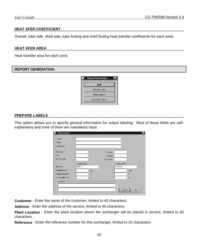
User’s Guide CC-THERM Version 5.4
42
HEAT XFER COEFFICIENT
Overall, tube side, shell side, tube fouling and shell fouling heat transfer coefficients for each zone.
HEAT XFER AREA
Heat transfer area for each zone.
REPORT GENERATION
PREPARE LABELS
This option allows you to specify general information for output labeling. Most of these fields are self-explanatory and none of them are mandatory input.
Customer - Enter the name of the customer, limited to 40 characters. Address - Enter the address of the service, limited to 40 characters. Plant Location - Enter the plant location where the exchanger will be placed in service, limited to 40 characters. Reference - Enter the reference number for this exchanger, limited to 10 characters.
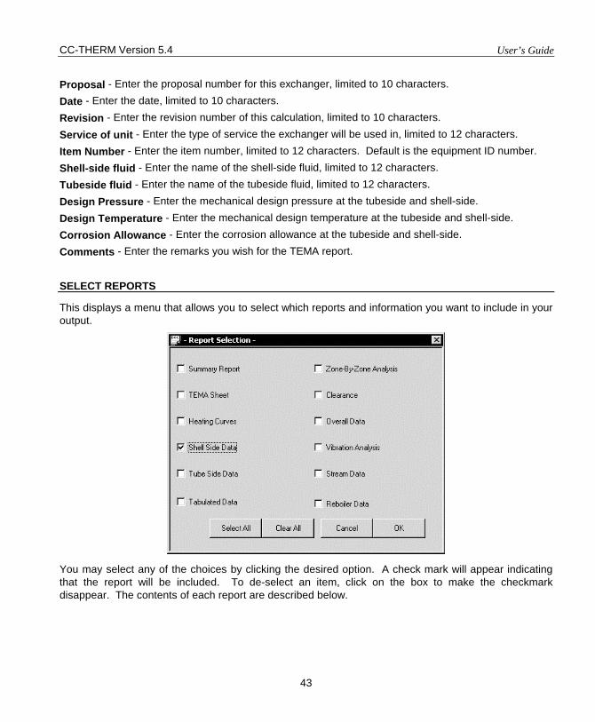
CC-THERM Version 5.4 User’s Guide
43
Proposal - Enter the proposal number for this exchanger, limited to 10 characters. Date - Enter the date, limited to 10 characters. Revision - Enter the revision number of this calculation, limited to 10 characters. Service of unit - Enter the type of service the exchanger will be used in, limited to 12 characters. Item Number - Enter the item number, limited to 12 characters. Default is the equipment ID number. Shell-side fluid - Enter the name of the shell-side fluid, limited to 12 characters. Tubeside fluid - Enter the name of the tubeside fluid, limited to 12 characters. Design Pressure - Enter the mechanical design pressure at the tubeside and shell-side. Design Temperature - Enter the mechanical design temperature at the tubeside and shell-side. Corrosion Allowance - Enter the corrosion allowance at the tubeside and shell-side. Comments - Enter the remarks you wish for the TEMA report.
SELECT REPORTS
This displays a menu that allows you to select which reports and information you want to include in your output.
You may select any of the choices by clicking the desired option. A check mark will appear indicating that the report will be included. To de-select an item, click on the box to make the checkmark disappear. The contents of each report are described below.
User’s Guide CC-THERM Version 5.4
44
GENERATE REPORTS
Clicking on this option will cause the selected reports to be assembled into a single formatted output and then displayed in Wordpad. Samples and explanations of each report are provided below in a later section.
SAVE CONFIGURATION
This command saves the current input for a rating case.
RE-ENTER STREAM INFORMATION
This command displays the STREAM Dialog boxes for the four streams going in and out of the current heat exchanger. These streams can be modified and the heat curve regenerated using this feature.
RE-INTIALIZE EXCHANGER
This command deletes all of the input and output data for the current exchanger and starts a new analysis.
CC-THERM OUTPUT
SUMMARY REPORT
This report section includes general data and a summary of the key information regarding the current exchanger. It contains physical configuration, heat transfer information and information describing the thermodynamic options and engineering units being used. An example of this report appears below:
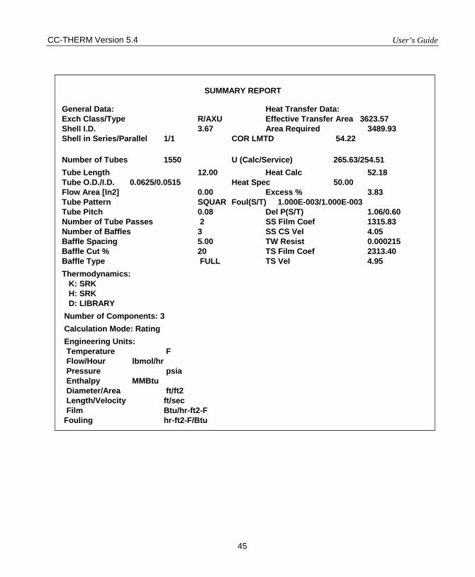
CC-THERM Version 5.4 User’s Guide
45
SUMMARY REPORT
General Data: Heat Transfer Data: Exch Class/Type R/AXU Effective Transfer Area 3623.57 Shell I.D. 3.67 Area Required 3489.93 Shell in Series/Parallel 1/1 COR LMTD 54.22
Number of Tubes 1550 U (Calc/Service) 265.63/254.51 Tube Length 12.00 Heat Calc 52.18 Tube O.D./I.D. 0.0625/0.0515 Heat Spec 50.00 Flow Area [In2] 0.00 Excess % 3.83 Tube Pattern SQUAR Foul(S/T) 1.000E-003/1.000E-003 Tube Pitch 0.08 Del P(S/T) 1.06/0.60 Number of Tube Passes 2 SS Film Coef 1315.83 Number of Baffles 3 SS CS Vel 4.05 Baffle Spacing 5.00 TW Resist 0.000215 Baffle Cut % 20 TS Film Coef 2313.40 Baffle Type FULL TS Vel 4.95 Thermodynamics: K: SRK H: SRK D: LIBRARY Number of Components: 3 Calculation Mode: Rating Engineering Units: Temperature F Flow/Hour lbmol/hr Pressure psia Enthalpy MMBtu Diameter/Area ft/ft2 Length/Velocity ft/sec Film Btu/hr-ft2-F Fouling hr-ft2-F/Btu
User’s Guide CC-THERM Version 5.4
46
TEMA SHEET
The TEMA Sheet is reproduced from the TEMA book and is filled in for use as an equipment spec sheet. An example is given on the next page. Most of the items on the TEMA Sheet are self-explanatory. Only a few of them will be explained here, as these few may not be intuitively obvious.
Surf/unit The total surface area per unit. The first value is the gross or overall area
without discounting any part of the tube length which may be imbedded in the tubesheet or covered by the baffles. The second number given is the effective surface area after subtracting any portion of the tube length embedded in the tubesheet or covered by baffles.
RHO-V2-inlet nozzle This is momentum term of the incoming shellside fluid at the inlet nozzle.
RHO-V2-bundle entrance
The momentum term of the incoming shellside fluid at the bundle entrance.
RHO-V2-bundle exit The momentum term of the leaving shellside fluid at the bundle exit.
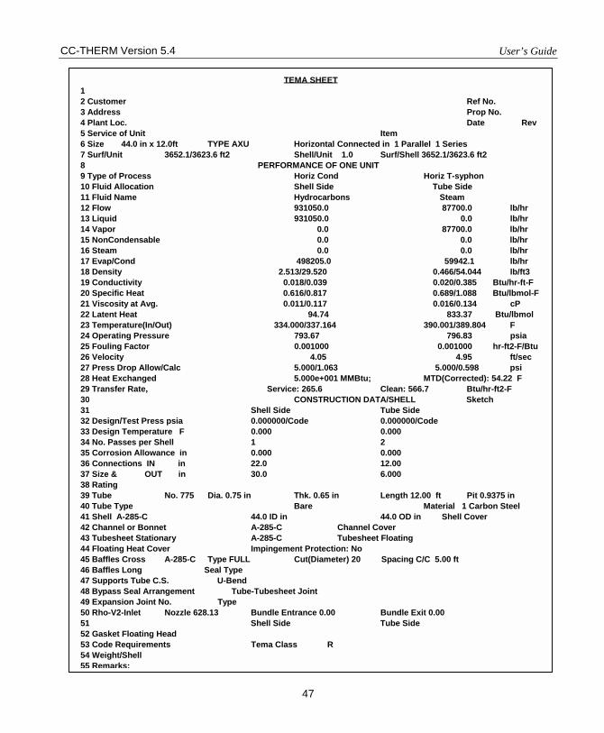
CC-THERM Version 5.4 User’s Guide
47
TEMA SHEET 1 2 Customer Ref No. 3 Address Prop No. 4 Plant Loc. Date Rev 5 Service of Unit Item 6 Size 44.0 in x 12.0ft TYPE AXU Horizontal Connected in 1 Parallel 1 Series 7 Surf/Unit 3652.1/3623.6 ft2 Shell/Unit 1.0 Surf/Shell 3652.1/3623.6 ft2 8 PERFORMANCE OF ONE UNIT 9 Type of Process Horiz Cond Horiz T-syphon 10 Fluid Allocation Shell Side Tube Side 11 Fluid Name Hydrocarbons Steam 12 Flow 931050.0 87700.0 lb/hr 13 Liquid 931050.0 0.0 lb/hr 14 Vapor 0.0 87700.0 lb/hr 15 NonCondensable 0.0 0.0 lb/hr 16 Steam 0.0 0.0 lb/hr 17 Evap/Cond 498205.0 59942.1 lb/hr 18 Density 2.513/29.520 0.466/54.044 lb/ft3 19 Conductivity 0.018/0.039 0.020/0.385 Btu/hr-ft-F 20 Specific Heat 0.616/0.817 0.689/1.088 Btu/lbmol-F 21 Viscosity at Avg. 0.011/0.117 0.016/0.134 cP 22 Latent Heat 94.74 833.37 Btu/lbmol 23 Temperature(In/Out) 334.000/337.164 390.001/389.804 F 24 Operating Pressure 793.67 796.83 psia 25 Fouling Factor 0.001000 0.001000 hr-ft2-F/Btu 26 Velocity 4.05 4.95 ft/sec 27 Press Drop Allow/Calc 5.000/1.063 5.000/0.598 psi 28 Heat Exchanged 5.000e+001 MMBtu; MTD(Corrected): 54.22 F 29 Transfer Rate, Service: 265.6 Clean: 566.7 Btu/hr-ft2-F 30 CONSTRUCTION DATA/SHELL Sketch 31 Shell Side Tube Side 32 Design/Test Press psia 0.000000/Code 0.000000/Code 33 Design Temperature F 0.000 0.000 34 No. Passes per Shell 1 2 35 Corrosion Allowance in 0.000 0.000 36 Connections IN in 22.0 12.00 37 Size & OUT in 30.0 6.000 38 Rating 39 Tube No. 775 Dia. 0.75 in Thk. 0.65 in Length 12.00 ft Pit 0.9375 in 40 Tube Type Bare Material 1 Carbon Steel 41 Shell A-285-C 44.0 ID in 44.0 OD in Shell Cover 42 Channel or Bonnet A-285-C Channel Cover 43 Tubesheet Stationary A-285-C Tubesheet Floating 44 Floating Heat Cover Impingement Protection: No 45 Baffles Cross A-285-C Type FULL Cut(Diameter) 20 Spacing C/C 5.00 ft 46 Baffles Long Seal Type 47 Supports Tube C.S. U-Bend 48 Bypass Seal Arrangement Tube-Tubesheet Joint 49 Expansion Joint No. Type 50 Rho-V2-Inlet Nozzle 628.13 Bundle Entrance 0.00 Bundle Exit 0.00 51 Shell Side Tube Side 52 Gasket Floating Head 53 Code Requirements Tema Class R 54 Weight/Shell 55 Remarks:
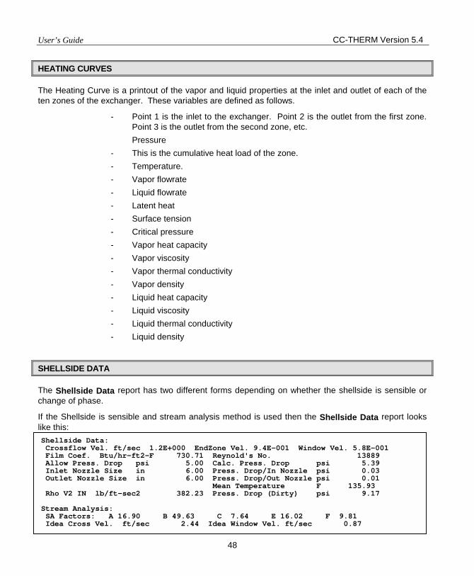
User’s Guide CC-THERM Version 5.4
48
HEATING CURVES
The Heating Curve is a printout of the vapor and liquid properties at the inlet and outlet of each of the ten zones of the exchanger. These variables are defined as follows.
- Point 1 is the inlet to the exchanger. Point 2 is the outlet from the first zone. Point 3 is the outlet from the second zone, etc.
Pressure - This is the cumulative heat load of the zone. - Temperature. - Vapor flowrate - Liquid flowrate - Latent heat - Surface tension - Critical pressure - Vapor heat capacity - Vapor viscosity - Vapor thermal conductivity - Vapor density - Liquid heat capacity - Liquid viscosity - Liquid thermal conductivity - Liquid density
SHELLSIDE DATA
The Shellside Data report has two different forms depending on whether the shellside is sensible or change of phase.
If the Shellside is sensible and stream analysis method is used then the Shellside Data report looks like this: Shellside Data: Crossflow Vel. ft/sec 1.2E+000 EndZone Vel. 9.4E-001 Window Vel. 5.8E-001 Film Coef. Btu/hr-ft2-F 730.71 Reynold's No. 13889 Allow Press. Drop psi 5.00 Calc. Press. Drop psi 5.39 Inlet Nozzle Size in 6.00 Press. Drop/In Nozzle psi 0.03 Outlet Nozzle Size in 6.00 Press. Drop/Out Nozzle psi 0.01 Mean Temperature F 135.93 Rho V2 IN lb/ft-sec2 382.23 Press. Drop (Dirty) psi 9.17 Stream Analysis: SA Factors: A 16.90 B 49.63 C 7.64 E 16.02 F 9.81 Idea Cross Vel. ft/sec 2.44 Idea Window Vel. ft/sec 0.87
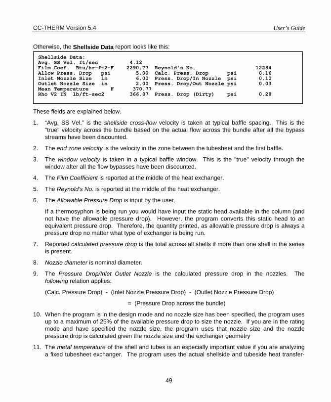
CC-THERM Version 5.4 User’s Guide
49
Otherwise, the Shellside Data report looks like this: These fields are explained below.
1. “Avg. SS Vel.” is the shellside cross-flow velocity is taken at typical baffle spacing. This is the "true" velocity across the bundle based on the actual flow across the bundle after all the bypass streams have been discounted.
2. The end zone velocity is the velocity in the zone between the tubesheet and the first baffle.
3. The window velocity is taken in a typical baffle window. This is the "true" velocity through the window after all the flow bypasses have been discounted.
4. The Film Coefficient is reported at the middle of the heat exchanger.
5. The Reynold’s No. is reported at the middle of the heat exchanger.
6. The Allowable Pressure Drop is input by the user.
If a thermosyphon is being run you would have input the static head available in the column (and not have the allowable pressure drop). However, the program converts this static head to an equivalent pressure drop. Therefore, the quantity printed, as allowable pressure drop is always a pressure drop no matter what type of exchanger is being run.
7. Reported calculated pressure drop is the total across all shells if more than one shell in the series is present.
8. Nozzle diameter is nominal diameter.
9. The Pressure Drop/Inlet Outlet Nozzle is the calculated pressure drop in the nozzles. The following relation applies:
(Calc. Pressure Drop) - (Inlet Nozzle Pressure Drop) - (Outlet Nozzle Pressure Drop)
= (Pressure Drop across the bundle)
10. When the program is in the design mode and no nozzle size has been specified, the program uses up to a maximum of 25% of the available pressure drop to size the nozzle. If you are in the rating mode and have specified the nozzle size, the program uses that nozzle size and the nozzle pressure drop is calculated given the nozzle size and the exchanger geometry
11. The metal temperature of the shell and tubes is an especially important value if you are analyzing a fixed tubesheet exchanger. The program uses the actual shellside and tubeside heat transfer-
Shellside Data: Avg. SS Vel. ft/sec 4.12 Film Coef. Btu/hr-ft2-F 2290.77 Reynold's No. 12284 Allow Press. Drop psi 5.00 Calc. Press. Drop psi 0.16 Inlet Nozzle Size in 6.00 Press. Drop/In Nozzle psi 0.10 Outlet Nozzle Size in 2.00 Press. Drop/Out Nozzle psi 0.03 Mean Temperature F 370.77 Rho V2 IN lb/ft-sec2 366.87 Press. Drop (Dirty) psi 0.28
User’s Guide CC-THERM Version 5.4
50
coefficients (and considers the exchanger to be in the fouled condition) to calculate this temperature.
These values are used by mechanical engineers for stress analysis. Also, the tube wall temperature is used frequently in the calculation of condensation and evaporation heat transfer.
12. The shellside pressure drop (dirty) is the pressure drop in the exchanger in the fouled condition. Calculating the shellside pressure drop with possible flow bypasses (such as the clearance between the baffle holes and the tubes) reduced somewhat (to simulate a fouled condition) does this.
13. Rho V2 IN is the flow momentum term at the shellside inlet nozzle. It is obtained by multiplying the fluid density by the square of the fluid velocity. This is an important term when the incoming fluid is in the vapor state. TEMA makes recommendations as to the maximum value this parameter may have before needing an impingement plate.
14. The stream analysis data are explained below.
SA factor A is that percentage of the shellside flow, which is leaking between the tubes and the holes in the baffle plates. SA factor B only has significance when there is sensible flow on the exchanger shellside. When there is change of phase on the shellside, this quantity will always be output as 0. When there is sensible flow on the shellside, the B STREAM refers to that portion of the shellside flow, which is in cross flow across the bundle. The closer this quantity is to 100%, the more efficient the flow. SA factor C is the percentage of the shellside flow, which is leaking between the bundle and the internal diameter of the shell. For a fixed tubesheet exchanger, the empty space between the bundle and the internal diameter of the shell is usually small and thus the C STREAM is a small percentage. However, for a floating head design (TEMA P, S, or T), this empty space becomes large and (if sealing strips are not used) thus the C STREAM percentage becomes large. When you specify sealing strips for a floating head, you will notice a significant reduction in the percentage of the C STREAM and an increase in the B STREAM (the "true" cross flow component of the bundle). Referred to the above discussion on OTLC for more information on the use of sealing strips. SA factor E is that percentage of the shellside flow, which is leaking between the baffle outer diameter and the shellside internal diameter. SA factor F is that percentage of the shellside flow which is leaking through the empty spaces left by the tubeside pass partition (pass partition lanes). Even though the partition lane will always be present for two or more tubeside passes, it may or may not affect the flow depending on the direction of the baffle cut and the pass arrangement. (See the above discussion on the pass arrangement in the Clearances menu). Below is a listing of the more common situations in which a pass partition lane will have an effect on the shellside flow. This listing uses an E shell. For an F shell, other variations are possible.
15. Ideal cross velocity is the ideal cross flow velocity of the shellside fluid across the bundle. This would only be the case if all leakage paths were non-existent.
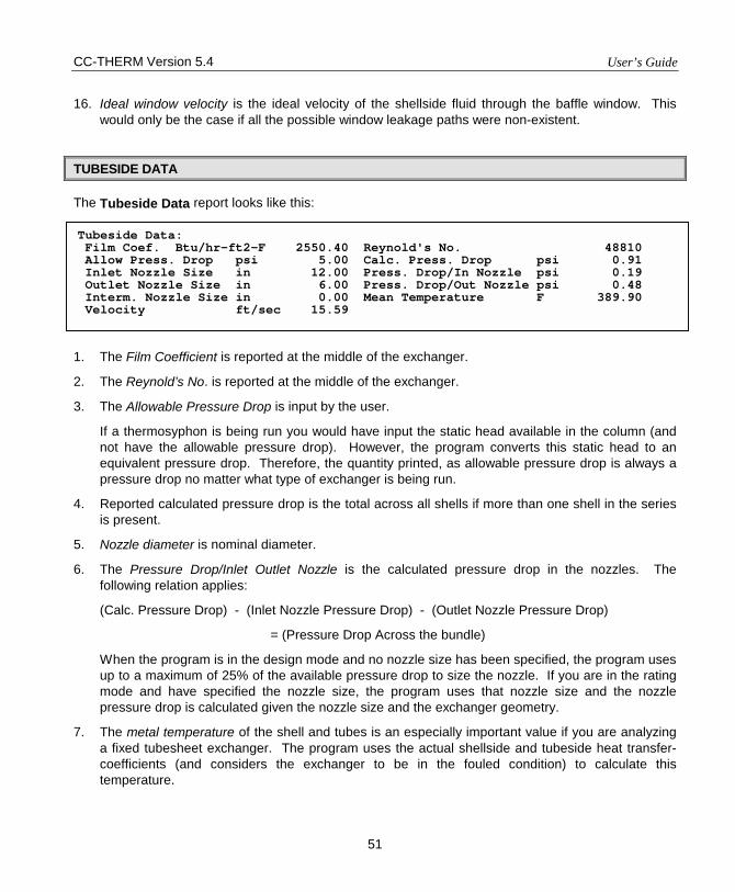
CC-THERM Version 5.4 User’s Guide
51
16. Ideal window velocity is the ideal velocity of the shellside fluid through the baffle window. This would only be the case if all the possible window leakage paths were non-existent.
TUBESIDE DATA
The Tubeside Data report looks like this:
1. The Film Coefficient is reported at the middle of the exchanger.
2. The Reynold’s No. is reported at the middle of the exchanger.
3. The Allowable Pressure Drop is input by the user.
If a thermosyphon is being run you would have input the static head available in the column (and not have the allowable pressure drop). However, the program converts this static head to an equivalent pressure drop. Therefore, the quantity printed, as allowable pressure drop is always a pressure drop no matter what type of exchanger is being run.
4. Reported calculated pressure drop is the total across all shells if more than one shell in the series is present.
5. Nozzle diameter is nominal diameter.
6. The Pressure Drop/Inlet Outlet Nozzle is the calculated pressure drop in the nozzles. The following relation applies:
(Calc. Pressure Drop) - (Inlet Nozzle Pressure Drop) - (Outlet Nozzle Pressure Drop)
= (Pressure Drop Across the bundle)
When the program is in the design mode and no nozzle size has been specified, the program uses up to a maximum of 25% of the available pressure drop to size the nozzle. If you are in the rating mode and have specified the nozzle size, the program uses that nozzle size and the nozzle pressure drop is calculated given the nozzle size and the exchanger geometry.
7. The metal temperature of the shell and tubes is an especially important value if you are analyzing a fixed tubesheet exchanger. The program uses the actual shellside and tubeside heat transfer-coefficients (and considers the exchanger to be in the fouled condition) to calculate this temperature.
Tubeside Data: Film Coef. Btu/hr-ft2-F 2550.40 Reynold's No. 48810 Allow Press. Drop psi 5.00 Calc. Press. Drop psi 0.91 Inlet Nozzle Size in 12.00 Press. Drop/In Nozzle psi 0.19 Outlet Nozzle Size in 6.00 Press. Drop/Out Nozzle psi 0.48 Interm. Nozzle Size in 0.00 Mean Temperature F 389.90 Velocity ft/sec 15.59
User’s Guide CC-THERM Version 5.4
52
These values are used by mechanical engineers for stress analysis. Also, the tube wall temperature is used frequently in the calculation of condensation and evaporation heat transfer.
8. The Velocity is reported at the center of the exchanger. If a change of phase is occurring, this is the two-phase velocity.
TABULATED DATA
The Tabulated Data report is a one-page summary of the exchanger. Most information is self-explanatory, but you should make note of the following points.
1. Above 24-inches nominal diameter, the shell OD printed out will equal the shell ID printed out. This is because below 24-inches, the program assumes the shell is pipe and above 24-inches, it is rolled plate for carbon steel construction. For stainless steel, the break point is 12-inches. Pipe wall thicknesses are known (standard wall), but since the program does no wall thickness calculation, rolled plate thicknesses are not. As a result, the shell ID is printed in both fields.
2. For a kettle reboiler, the kettle ID is printed in the shell OD field, and the tube bundle diameter is printed in the shell ID field.
3. All clearances are diametrical.
4. When the shell nozzles are on opposite sides of the shell and segmental baffles are being used, the number of baffles will be an even number. When the shell nozzles are on the same side of the shell and segmental baffles are being used, the total number of baffles will be an odd number. When rod baffles are being used, this number can be disregarded since rod baffles are really tube supports and there are no cross baffles as such as with the other baffle types. If the NTIW (No Tubes-in-Window) type baffle is being used, the number of baffles given refers only to the NTIW baffles themselves and does not include any intermediate baffles which may have been used to lessen the effects of vibration.
5. The baffle spacing is the center spacing of the baffles -- this would be the applicable baffle spacing of all those baffles, which are not immediately adjacent to the tube sheets. The baffle inlet spacing is the baffle spacing between the front tubesheet and the first baffle.
6. Baffle types are as follows.
SSEG - Single segmental DSEG - Double segmental TSEG - Triple segmental NTIW - No Tubes-in-Window Disk - Disk and Donut RODB - Rod
7. The tube number is the number of tubes in the tube bundle. If you have a U-tube bundle, the number output would be the number of tubes, not the number of holes in the tubesheet.
CC-THERM Version 5.4 User’s Guide
53
8. Tube outside diameter is the outer diameter of the tube. For low-fin radial tubes, this diameter will be the tube nominal diameter.
9. Tube inside diameter is the inner diameter of the tube. For low-fin radial tubes, this diameter will vary due to the undulations on the inner surface of the tube, but the program continues print out of the nominal inner diameter of the tubes.
10. The tubewall thickness is the wall nominal thickness of the tube. For low-fin radial tubes, this thickness will vary and the minimum thickness will be somewhat less than the nominal thickness. However, the program continues print out of the nominal wall thickness.
11. The tube pitch is the distance between the center of the tubes.
12. The tube pattern in the tubesheet may be:
TRI60 - Triangular SQUA - Double segmental baffle DIAM - Diamond (45) TRI30 - Rotated triangular (30)
13. Tube pass type may be ribbon, quadratic, or mixed.
14. The outer tube limit is the outer diameter of the tube bundle. This limit diameter is based on that tube which is furthest removed from the geometrical center of the exchanger.
15. The outer tube limit clearance (OTLC) is the diametrical clearance between the Outer Tube Limit and the internal diameter of the shell. This is a very important piece of information and it has a pronounced effect on shellside heat transfer and pressure drop. If the exchanger rear head is of a fixed type (TEMA types L, M, and N) or a floating tubesheet (TEMA type W) or a U-tube construction, the OTLC is usually small (0.5-inches, 12-mm, or less) and so there is usually only a minimum amount of shellside fluid bypassing the tube bundle. On the other hand, the OTLC dimension for floating head types (TEMA types P, S, and T) is usually considerable. When the program is in the design mode and the OTLC dimension is found to be excessive, the program automatically puts in sealing strips to force the flow, which bypasses the bundle back through the bundle. Thus, for a design of any floating head unit, the program will typically put in sealing strips. However, when the program is in the rating mode (regardless of the construction), the program will leave it up to you whether or not to put in sealing strips. If you make a rating of a unit which you know to have a small OTLC and the program calculates a substantially larger OTLC (resulting in large bypasses and poor heat transfer characteristics), you should rerun the problem and fix the OTLC to the known value and rerun the problem. See the discussion above concerning setting the OTLC value in the Clearances menu. As a general rule, you should check the OTLC calculated by the program after every rating run.
16. The bundle top space is the void space at the top of the bundle and is the distance measured from the intersection of the shell inlet nozzle and the shell to the outside diameter of the top row of the tube bundle. If the program has placed an impingement plate on the bundle, the top few rows usually (but not always) must be removed. Also, if you are using No Tubes-in-Window type baffles, this distance (as defined above) will appear in the output whether or not you have an
User’s Guide CC-THERM Version 5.4
54
impingement plate. Also, you may have occasion to declare a void space at the top of the bundle - for instance, for a shellside condenser with an X shell to permit uniform vapor distribution across the tubes. Such a void space should be declared on the Clearances menu.
17. The bundle btm. (bottom) space is the void space at the bottom bundle. This is a quantity, which appears far less frequently than the above parameter. It is the mirror image of the above parameter as it appears at the bottom of the bundle. This quantity will appear in the output in either of the following two circumstances.
• You are using NTIW baffles, or • You have input this space on the Clearances menu
18. The words "Impingement plate" in the impingement plate field indicates that an impingement plate does exist at the shellside inlet nozzle. If the Bundle Top Space is simultaneously a value of zero, this indicates that the impingement plate has been placed inside the inlet nozzle (which in this case would be flared). If an impingement plate is present and the Bundle Top Space is non-zero, the impingement plate has been placed on the top of the bundle. To accommodate the plate, a few rows of tubes must be removed.
19. The bonnet diameter is the inner diameter on the channel side of the exchanger. This parameter only becomes important when you have a pipe for the channel section and have high pressure on the tubeside. In this instance, the internal diameter will grow inward (since it is a pipe) and may even be smaller than the inside diameter of the shell. If provisions are not made for the smaller diameter on the channel side, the outer row of the tube bundle may not fit inside the channel. The program always checks for situations such as this, but to be on the safe side, you can specify the channel internal diameter on the Clearances menu.
20. Anytime there are two or more tubeside passes, a pass clearance lane will always exist to accommodate the pass partitions, which separate the various tubeside passes on the channel side. This lane cuts a void space throughout the entire bundle and will always have some effect on the flow distribution on the shellside of the exchanger. The program always calculates this quantity internally. This quantity only appears in the output if you specify it directly on the Clearances menu.
21. The orientation refers to the position of the exchanger. H is horizontal and V is vertical.
22. Clearances are diametrical.
ZONE-BY-ZONE ANALYSIS
As the name implies, more detail is given about the two-phase calculation of the heat transfer coefficient and the pressure drop. This information is given at each of the ten zones the program uses to make the calculation. This information may pertain to a condenser calculation or an evaporation calculation. The outputs are similar but not identical.
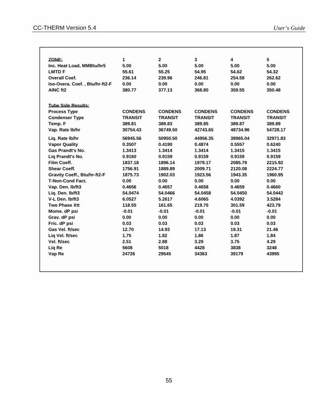
CC-THERM Version 5.4 User’s Guide
55
ZONE: 1 2 3 4 5 Inc. Heat Load, MMBtu/hr5 5.00 5.00 5.00 5.00 5.00 LMTD F 55.61 55.25 54.95 54.62 54.32 Overall Coef. 236.14 239.96 246.81 254.58 262.62 Iso-Overa. Coef. , Btu/hr-ft2-F 0.00 0.00 0.00 0.00 0.00 AINC ft2 380.77 377.13 368.80 359.55 350.48 Tube Side Results: Process Type CONDENS CONDENS CONDENS CONDENS CONDENS Condenser Type TRANSIT TRANSIT TRANSIT TRANSIT TRANSIT Temp. F 389.81 389.83 389.85 389.87 389.89 Vap. Rate lb/hr 30754.43 36749.50 42743.65 48734.96 54728.17
Liq. Rate lb/hr 56945.56 50950.50 44956.35 38965.04 32971.83 Vapor Quality 0.3507 0.4190 0.4874 0.5557 0.6240 Gas Prandt's No. 1.3413 1.3414 1.3414 1.3415 1.3415 Liq Prandt's No. 0.9160 0.9159 0.9159 0.9159 0.9159 Film Coeff. 1837.18 1896.14 1979.17 2085.79 2215.92 Shear Coeff. 1756.91 1889.89 2009.71 2120.08 2224.77 Gravity Coeff., Btu/hr-ft2-F 1875.73 1902.03 1923.56 1943.35 1960.95 T-Non-Cond Fact. 0.00 0.00 0.00 0.00 0.00 Vap. Den. lb/ft3 0.4656 0.4657 0.4658 0.4659 0.4660 Liq. Den. lb/ft3 54.0474 54.0466 54.0458 54.0450 54.0442 V-L Den. lb/ft3 6.0527 5.2617 4.6065 4.0392 3.5284 Two Phase Xtt 118.55 161.65 219.75 301.59 423.79 Mome. dP psi -0.01 -0.01 -0.01 -0.01 -0.01 Grav. dP psi 0.00 0.00 0.00 0.00 0.00 Fric. dP psi 0.03 0.03 0.03 0.03 0.03 Gas Vel. ft/sec 12.70 14.93 17.13 19.31 21.46 Liq Vel. ft/sec 1.75 1.82 1.86 1.87 1.84 Vel. ft/sec 2.51 2.88 3.29 3.75 4.29 Liq Re 5608 5018 4428 3838 3248 Vap Re 24726 29545 34363 39179 43995
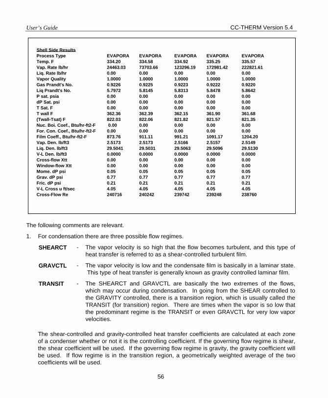
User’s Guide CC-THERM Version 5.4
56
The following comments are relevant.
1. For condensation there are three possible flow regimes.
SHEARCT - The vapor velocity is so high that the flow becomes turbulent, and this type of heat transfer is referred to as a shear-controlled turbulent film.
GRAVCTL - The vapor velocity is low and the condensate film is basically in a laminar state. This type of heat transfer is generally known as gravity controlled laminar film.
TRANSIT - The SHEARCT and GRAVCTL are basically the two extremes of the flows, which may occur during condensation. In going from the SHEAR controlled to the GRAVITY controlled, there is a transition region, which is usually called the TRANSIT (for transition) region. There are times when the vapor is so low that the predominant regime is the TRANSIT or even GRAVCTL for very low vapor velocities.
The shear-controlled and gravity-controlled heat transfer coefficients are calculated at each zone of a condenser whether or not it is the controlling coefficient. If the governing flow regime is shear, the shear coefficient will be used. If the governing flow regime is gravity, the gravity coefficient will be used. If flow regime is in the transition region, a geometrically weighted average of the two coefficients will be used.
Shell Side Results Process Type EVAPORA EVAPORA EVAPORA EVAPORA EVAPORA Temp. F 334.20 334.58 334.92 335.25 335.57 Vap. Rate lb/hr 24463.03 73703.66 123296.19 172981.42 222821.61 Liq. Rate lb/hr 0.00 0.00 0.00 0.00 0.00 Vapor Quality 1.0000 1.0000 1.0000 1.0000 1.0000 Gas Prandt's No. 0.9226 0.9225 0.9223 0.9222 0.9220 Liq Prandt's No. 5.7972 5.8145 5.8313 5.8478 5.8642 P sat. psia 0.00 0.00 0.00 0.00 0.00 dP Sat. psi 0.00 0.00 0.00 0.00 0.00 T Sat. F 0.00 0.00 0.00 0.00 0.00 T wall F 362.36 362.39 362.15 361.90 361.68 (Twall-Tsat) F 822.03 822.06 821.82 821.57 821.35 Nuc. Boi. Coef., Btu/hr-ft2-F 0.00 0.00 0.00 0.00 0.00 For. Con. Coef., Btu/hr-ft2-F 0.00 0.00 0.00 0.00 0.00 Film Coeff., Btu/hr-ft2-F 873.76 911.11 991.21 1091.17 1204.20 Vap. Den. lb/ft3 2.5173 2.5173 2.5166 2.5157 2.5149 Liq. Den. lb/ft3 29.5041 29.5031 29.5063 29.5096 29.5130 V-L Den. lb/ft3 0.0000 0.0000 0.0000 0.0000 0.0000 Cross-flow Xtt 0.00 0.00 0.00 0.00 0.00 Window-flow Xtt 0.00 0.00 0.00 0.00 0.00 Mome. dP psi 0.05 0.05 0.05 0.05 0.05 Grav. dP psi 0.77 0.77 0.77 0.77 0.77 Fric. dP psi 0.21 0.21 0.21 0.21 0.21 V-L Cross u ft/sec 4.05 4.05 4.05 4.05 4.05 Cross-Flow Re 240716 240242 239742 239248 238760
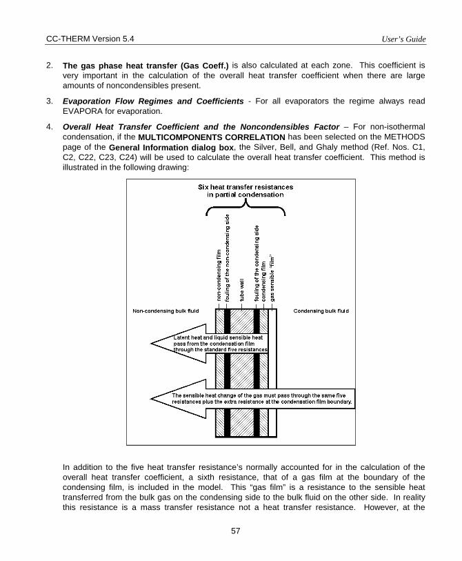
CC-THERM Version 5.4 User’s Guide
57
2. The gas phase heat transfer (Gas Coeff.) is also calculated at each zone. This coefficient is very important in the calculation of the overall heat transfer coefficient when there are large amounts of noncondensibles present.
3. Evaporation Flow Regimes and Coefficients - For all evaporators the regime always read EVAPORA for evaporation.
4. Overall Heat Transfer Coefficient and the Noncondensibles Factor – For non-isothermal condensation, if the MULTICOMPONENTS CORRELATION has been selected on the METHODS page of the General Information dialog box, the Silver, Bell, and Ghaly method (Ref. Nos. C1, C2, C22, C23, C24) will be used to calculate the overall heat transfer coefficient. This method is illustrated in the following drawing:
In addition to the five heat transfer resistance’s normally accounted for in the calculation of the overall heat transfer coefficient, a sixth resistance, that of a gas film at the boundary of the condensing film, is included in the model. This “gas film” is a resistance to the sensible heat transferred from the bulk gas on the condensing side to the bulk fluid on the other side. In reality this resistance is a mass transfer resistance not a heat transfer resistance. However, at the
User’s Guide CC-THERM Version 5.4
58
present time calculation of the mass transfer resistance for the general case is not practical. Therefore, the SBG method substitutes the “calculateable” gas heat transfer resistance for the “uncalculateable” gas-liquid mass transfer resistance. This approach is conservative and generally produces overall coefficients somewhat less than the real situation. However, it is much better than omitting the resistance altogether. The presence of even small amounts of non-condensibles significantly lowers the real heat transfer coefficient. The pure condensing coefficient alone does not adequately represent the situation.
The overall procedure for the SGB method is outlined (in simplified form) below:
i. Calculate the film coefficients as normal.
ii. Calculate the overall heat transfer coefficient, U, as normal (one over the sum of the five heat transfer resistance).
iii. Calculate the gas coefficient at the condensing liquid boundary using standard sensible heat transfer methods.
iv. Calculate the non-condensable factor, F, (F-Non-Cons Fact on the zone-by-zone output) as a function of the gas coefficient and the sensible heat change of the gas across the zone.
v. Calculate the final overall heat transfer coefficient, Uo, as:
F1UUo +
=
If the non-condensibles factor is calculated, the zone-by-zone analysis will print out both the unadjusted overall heat transfer coefficient, U, (labeled the Iso-Overall Coefficient) and adjusted overall heat transfer coefficient, Uo, (labeled Overall Coefficient).
5. Two-Phase Pressure Drops - The calculation of two-phase pressure drops in CC-THERM can be broken into four parts.
• Two-phase multiplier • Gravity portion • Friction portion • Momentum portion
These are explained below.
Two-phase multiplier, Xtt - The two-phase multiplier is calculated at each zone. When there are large amounts of vapor present, the multiplier will be quite large. This multiplier is applied to each component of the pressure drop (momentum, gravity, and friction) and summed over all the zones to arrive at the overall pressure drop.
Momentum portion - The momentum portion of the pressure drop is calculated based on the assumption that the entire fluid is in the liquid state. A multiplier is calculated which corrects for the two-phase nature of the flow. This multiplier then multiplies the momentum pressure drop at each zone to calculate the overall two-phase pressure drop.
CC-THERM Version 5.4 User’s Guide
59
Gravity portion - The gravity portion of the pressure drop is meant to simulate the two-phase static head which will always exist in any two-phase situation and for a condenser will always be a pressure gain, although usually a very small quantity.
Friction portion - The frictional portion of the pressure drop is calculated based on the assumption that the entire fluid is in the liquid state. A multiplier is calculated which corrects for the two-phase nature of the flow. This multiplier then multiplies the frictional pressure drop at each zone to calculate the overall two-phase pressure drop.
6. The Nucleate Boiling Coefficient - In any evaporator, the heat transfer coefficient is a combination of the two-phase heat transfer coefficient and the nucleate boiling coefficient. For pool-type evaporation, nucleate boiling will predominate. For a vertical thermosyphon, the two-phase heat transfer coefficient will usually be predominate.
7. AINC is the incremental area of the zone. It is calculated like so:
iii
i CMTDUQAINC
•=
where, Qi = the heat duty of the zone Ui = the overall heat transfer coefficient (final) of the zone CMTDi = the corrected log menu temperature difference across the zone. CMTDi is the
LMTD of the zone times the correction factor for the entire exchanger. All zones use the same correction factor.
The total required area for the heat exchanger is the sum of all the AINCi’s.
8. The zone-by-zone analysis prints out the arithmetic average of the zone inlets and outlets for the following variables:
• Temperature • Vapor flowrate • Liquid flowrate • Vapor quality • Vapor density • Liquid density • Two-phase density
9. The following numbers are calculated from the average properties of the zone:
• Velocity • Reynold’s number • Prandtl number • Film coefficients
10. The “saturation variables” P saturation, dP sat., T sat., T wall, and (Twall – Tsat) are used only for evaporation.
User’s Guide CC-THERM Version 5.4
60
• P sat. stands for saturation pressure. Since any evaporation zone is saturated, P sat is actually the specified average pressure of the zone, Pi. For any evaporative zone,
mP*iPP.satP ini
∆−==
where, Pin = the inlet pressure to the heat exchanger i = the number of the current zone ∆P = the allowable pressure drop across the heat exchanger m = the total number of zones
• dP sat. is the “saturation pressure” at the tube wall temperature. This is a pseudo value used by the Forrester - Zuber equation. It is calculated using the Clasius-Clapyron equation:
−=
Twall1
Tsat1
RM*h
PsatdPsatIn LG
where, hLG = the latent heat of the fluid m = the moleculer weight of the fluid R = the gas law constant Tsat = the zone average temperature (explained below) Twall = the zone wall temperature (explained below)
The Clasuis-Clapyron equation is for pure components, but is used by the Forrester-Zuber Method as a satisfactory approximation.
• Tsat. Is the average zone temperature and is taken from the heat curve. • Twall is the tube wall temperature. The tube wall temperature is calculated by solving the
heat balance across each heat transfer boundary. • (Twall – Tsat) is the difference between the tube wall temperature and the bulk fluid
temperature. This quantity has a strong influence upon nucleate boiling coefficients.
11. For sensible shell side cases, stream analysis data will be printed out zone-by-zone if stream analysis method is used. These data is explained in section 14 of SHELLSIDE DATA.
CLEARANCE
This report tabulates the clearances used in the exchanger calculations. All clearances are diametrical except for the bundle top space and the bundle bottom space, which are radial.
OVERALL DATA
1. The Area Total is the total installed area of the heat exchanger. It is the total surface area of a single tube times the total number of tubes. For U-tubes, only the straight length of the tube is
CC-THERM Version 5.4 User’s Guide
61
used unless the user enters a value for the U-bend efficiency. For low radial finned tubes, the area is the total area of the fins.
2. The Area Effective of the exchanger excludes that portion of the tube length, which is covered by the tubesheet and the baffles. Also, for a U-tube bundle, the U-bend is not included in the surface area calculation depending on what has been input for the U-tube efficiency. The default for the U-tube efficiency is 0%, i.e., the U-bend will not be included.
3. The Area Required is that area needed to transfer the specified heat duty of the exchanger. This value is determined by summing the incremental areas, AINCi’s of all the zones.
4. The Area per Shell is the effective area divided by the number of shells.
5. The % excess is the excess area for the present calculation. This value is always expressed as a percent. A negative value indicates that the exchanger is undersurfaced. When making a design run, the program usually terminates the calculation when the excess area is between 0 and 5%. Occasionally, when making a design run, the % EXCESS will turn out to be slightly negative, and this is usually acceptable to most users. If this is not acceptable, you can do one of two things.
a. Make the run one more time, fixing the heat load at a value 3% or 4% higher than the maximum heat load, or
b. Make a rating with a shell size just slightly greater than the one just designed.
6. The Heat Duty is the calculation heat load, which is the larger of the calculated or user-supplied heat load.
7. U Service is the exchanger service heat transfer coefficient. This quantity is not a function of the calculated heat transfer coefficients. It depends on the heat load, the CMTD, and the effective surface area:
CMTD*AreaTOTALQServiceU =
where, Q TOTAL = the heat duty of the exchanger Area = the total effective of the exchanger CMTD = the corrected log mean temperature difference
8. U Calc is the calculated overall heat transfer coefficient for the whole exchanger. Since an overall heat transfer coefficient, Ui, is calculated for each zone, the definition of U Calc is somewhat a matter of convention. CC-THERM defines U Calc as:
)WCMTD(.)qReArea(TotalQCalcU =
User’s Guide CC-THERM Version 5.4
62
where, Q Total = the heat duty of the exchanger Area Req = the required area which is the sum of the incremental areas for all
zones WCMTD = the weighted corrected log mean temperature difference which is
calculated like so:
∑=
iCMTDiQ
TOTALQWCMTD
where, Q TOTAL = the heat duty of the exchanger Qi = the incremental heat duty of zone i CMTDi = the corrected log mean temperature difference for zone i
9. Weight LMTD is the LMTD - Logarithmic Mean Temperature Difference before any correction factor is applied.
10. LMTD Corr Factor is the correction factor on the LMTD when a pure countercurrent flow condition does not exist. This factor is only printed when sensible flow exists on both the shellside and the tubeside.
11. CORR LMTD is the corrected LMTD. The program calculates the CORR LMTD in each of the zones and then calculates a weighted CORR LMTD.
VIBRATION ANALYSIS
Each time the program makes a thermal calculation; it also does a vibrational analysis of the exchanger shellside. There are some general points about this analysis, which should be noted here.
The program makes several checks to insure that there is no vibrational problem. These include the following.
1. The Connors method for fluid elastic vibration (basically for liquids)
2. The Chen method for the vortex shedding frequency (basically for gases)
3. The Owen method for the turbulent buffeting frequency (basically for gases)
4. The Thorngren method for baffle damage
When the shellside fluid is a liquid, the Connors method is the most important determinant of a vibration problem. When the fluid is a liquid and the velocity in the given span exceeds the Connors' critical velocity, the program considers four different criteria based on the Chen and Owen method to decide whether a vibration problem exists.
CC-THERM Version 5.4 User’s Guide
63
1. Ratio of vortex shedding frequency to natural frequency is greater than 0.5
2. Ratio of vortex shedding frequency to acoustic frequency is greater than 0.8 and less than 1.2
3. Ratio of turbulence buffeting frequency to natural frequency is greater than 0.5
4. Ratio of turbulence buffeting frequency to acoustic frequency is greater than 0.8 and less than 1.2
When you have a two-phase situation, whether it is an evaporator or a condenser, the program makes the vibration analysis based upon the highest fluid velocity (generally the vapor velocity). This is a gray area since the methods of analysis are based upon a single fluid state. The presence of liquid will tend to dampen the effect of vortex shedding and turbulent buffeting. This is not explicitly accounted for in these methods. It is thus left to the user to make an educated judgement, based on the numbers, which the program generates, as to whether a vibration problem exists or not.
The program always checks for a vibration problem at three different locations.
1. The entrance baffle span (between the tubesheet and the first baffle)
2. The center baffle span (at a typical baffle center span location)
3. The exit baffle span (between the last baffle and the rear tubesheet)
There are possible several steps to take once a vibration problem does occur, and they usually entail changing the natural frequency of the bundle in one way or another. Some of these include.
1. Shorten baffle spacing
2. Use No Tubes-in-Window Baffles
3. Use No Tubes-in-Window Baffles with intermediate support plates
4. Use Rod Baffles
5. Reduce the shellside velocities
When rod baffles are used, the program uses spacing between rod baffles of six inches. The rod baffle calculations in the program are based on a single-phase fluid. The program allows the use of rod baffles for a change-of-phase on the shellside but the results should be analyzed carefully. If you have a G, H, K or X shell with either condensation or evaporation on the shellside, the results should be reliable. If you have an E, F, or J shell, it implies flow over and around baffles. Rod baffles are meant for longitudinal flow along the axis of the tubes. Thus, the program results will be less precise.
Tube span is the length of the span in question.
Cross-flow velocity is the shellside velocity at the span in question.
Critical velocity is the Connors critical velocity.
Ratio Vcross/Vcrit is the ratio of the actual velocity to the Connors critical velocity. When the fluid is a liquid and this ratio is greater than 1.0, the possibility of fluid elastic vibration exists and CC-THERM flags a problem.

User’s Guide CC-THERM Version 5.4
64
Natural Frequency (F Tube) is the first mode frequency of the tube in cycles per second. CC-THERM considers only the first mode in its vibration analysis. This produces a conservative result.
Acoustic Frequency (F AC) is the first acoustic frequency of the tube bundle. It is sometimes called the fundamental tone. It is calculated as follows:
d2U
f sa =
where, fa = the first acoustic frequency of the bundle Us = the velocity of sound in the shell side fluid d = the shell inside diameter
The acoustic frequency is always the same at the inlet, center, and outlet of the exchanger.
Vortex Shed. Freq. (F VS) is the vortex shedding frequency of the tube. Flow across a tube produces, or “sheds, a series of vortices in the downstream wake of a fluid flowing across a tube. This generates alternating forces, which occur more frequently as the velocity of flow increases. Vortex shedding can excite tube vibration when its frequency matches the natural frequency of the tubes, and can become “locked in” to the tube natural frequency even when the flow is increased.
Vortex shedding occurs the ranges 100 < Re < 105 and Re > 2x10⁶. It dies out in between.
CC-THERM uses the method of Chen to predict vortex-shedding frequencies. It should be noted that Chen’s data contained few points in the range of the most common industrial pitch ratios (1.25 through 1.75).
Turbu. Buff. Freq. (F TB) is the dominant turbulent buffeting frequency in cycles per second. CC-THERM uses the empirical equation of OWENS to predict this frequency:
+
−= 28.0
PD105.3
PPDUf
2
to
toc
tbl
where, Pl = the longitudinal tube pitch Pt = the transverse tube pitch Uc the crossflow velocity Do = the tube outside diameter
This equation was developed for gases and may not be applicable to liquids.
FVS/FTUB is the ratio of the vortex shedding frequency to the tube bundle natural frequency. When this ratio is greater than 0.5, a vibration problem is flagged.
FVS/FAC is the ratio of the vortex shedding frequency to the tube bundle acoustic frequency. When this ratio is in the range of 0.8 to 1.2, it indicates that a resonant condition exists and a vibration problem is flagged.
CC-THERM Version 5.4 User’s Guide
65
FTB/FTUB is the ratio of the turbulent buffeting frequency to the tube bundle natural frequency. When this ratio is greater than 0.5, a vibration problem is flagged.
FTB/FAC is the ratio of the turbulent buffeting frequency to the tube bundle acoustic frequency. When this ratio is in the range of 0.8 to 1.2, it indicates that a resonant condition exists and a vibration problem is flagged.
OPTIMIZATION
This portion of the output shows the optimization path that the program used to arrive at the final result. This optimization printout only occurs if you are in the design mode. The program deliberately begins with an obviously undersized unit in order to insure that the procedure does not miss the optimum result. The program uses basically five criteria to arrive at the optimum result.
1. Supplied area is greater than the required area
2. Pressure drop allowables are met on the shellside
3. Pressure drop allowables are met on the tubeside
4. Velocities on the shellside do not exceed the imposed limit
5. Velocities on the tubeside do not exceed the imposed limit
In order to find the smallest unit, which will satisfy these criteria, the program will vary the following parameters:
• shell inside diameter • tube length • baffle spacing • baffle cut • tube passes if selected on the design options dialog box
It will also attempt to stay close to the preferred tube length to shell diameter ratio specified on the General Information dialog box.
If the program makes a design and what appears to be the optimum point has been exceeded, it is probable that the program continued on the optimization path in order to satisfy the velocity limitation. When this occurs, you can override the limits set by the program by making the appropriate entry in the General Information dialogue box.
Iter is the iteration number. Sact is the actual surface area (installed) of the heat exchanger. Sreq is the required surface area. This is the sum of the incremental areas for all the zones.
Conceptually, it is the area required to transfer the heat duty of the unit at the conditions prevailing within the unit.
User’s Guide CC-THERM Version 5.4
66
Uall is the overall heat transfer coefficient for the whole heat exchanger. Since an overall heat transfer coefficient is calculated for each zone, this value is a mater of convention. In CC-THERM it is determined as follows:
WCMTD*SreqQ
Uall TOTAL=
where, Qtotal = the heat duty of the exchanger Sreq = the required surface area (defined above) WCMTD = the weighted corrected log mean temperature difference (defined below)
aS is the film coefficient on the shell side. This is the coefficient for the middle zone. aT is the film coefficient on the tube side. This is the coefficient for the middle zone. dPS is the calculated pressure drop on the shell side. This includes nozzle and bundle pressure
losses. dPT is the calculated pressure drop on the tube side. This includes nozzle and bundle pressure
losses. Lb is the center baffle spacing. Cut is the baffle cut. velS is the shell side cross flow velocity in the middle zone. velT is the tube side velocity in the middle zone. diamS is the shell inside diameter. Lt is the tube length. nT is the number of tubes. In the case of U-tubes this is the number of holes in the tube sheet. nTP is the number of tube passes.
STREAM DATA
The stream data section allows you to include stream composition data in your printed output. It is analogous to the CHEMCAD Suite, except only those streams that are included in the exchanger will appear in the report.
REBOILER DATA
The Reboiler Data report provides detailed information for thermosyphon and kettle reboilers. It looks like this:
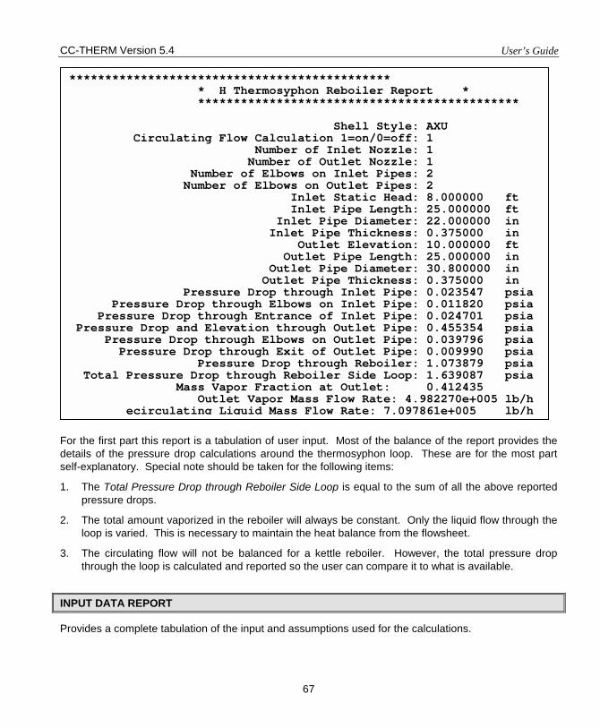
CC-THERM Version 5.4 User’s Guide
67
For the first part this report is a tabulation of user input. Most of the balance of the report provides the details of the pressure drop calculations around the thermosyphon loop. These are for the most part self-explanatory. Special note should be taken for the following items:
1. The Total Pressure Drop through Reboiler Side Loop is equal to the sum of all the above reported pressure drops.
2. The total amount vaporized in the reboiler will always be constant. Only the liquid flow through the loop is varied. This is necessary to maintain the heat balance from the flowsheet.
3. The circulating flow will not be balanced for a kettle reboiler. However, the total pressure drop through the loop is calculated and reported so the user can compare it to what is available.
INPUT DATA REPORT
Provides a complete tabulation of the input and assumptions used for the calculations.
********************************************* * H Thermosyphon Reboiler Report * ********************************************* Shell Style: AXU Circulating Flow Calculation 1=on/0=off: 1 Number of Inlet Nozzle: 1 Number of Outlet Nozzle: 1 Number of Elbows on Inlet Pipes: 2 Number of Elbows on Outlet Pipes: 2 Inlet Static Head: 8.000000 ft Inlet Pipe Length: 25.000000 ft Inlet Pipe Diameter: 22.000000 in Inlet Pipe Thickness: 0.375000 in Outlet Elevation: 10.000000 ft Outlet Pipe Length: 25.000000 in Outlet Pipe Diameter: 30.800000 in Outlet Pipe Thickness: 0.375000 in Pressure Drop through Inlet Pipe: 0.023547 psia Pressure Drop through Elbows on Inlet Pipe: 0.011820 psia Pressure Drop through Entrance of Inlet Pipe: 0.024701 psia Pressure Drop and Elevation through Outlet Pipe: 0.455354 psia Pressure Drop through Elbows on Outlet Pipe: 0.039796 psia Pressure Drop through Exit of Outlet Pipe: 0.009990 psia Pressure Drop through Reboiler: 1.073879 psia Total Pressure Drop through Reboiler Side Loop: 1.639087 psia Mass Vapor Fraction at Outlet: 0.412435 Outlet Vapor Mass Flow Rate: 4.982270e+005 lb/h ecirculating Liquid Mass Flow Rate: 7.097861e+005 lb/h
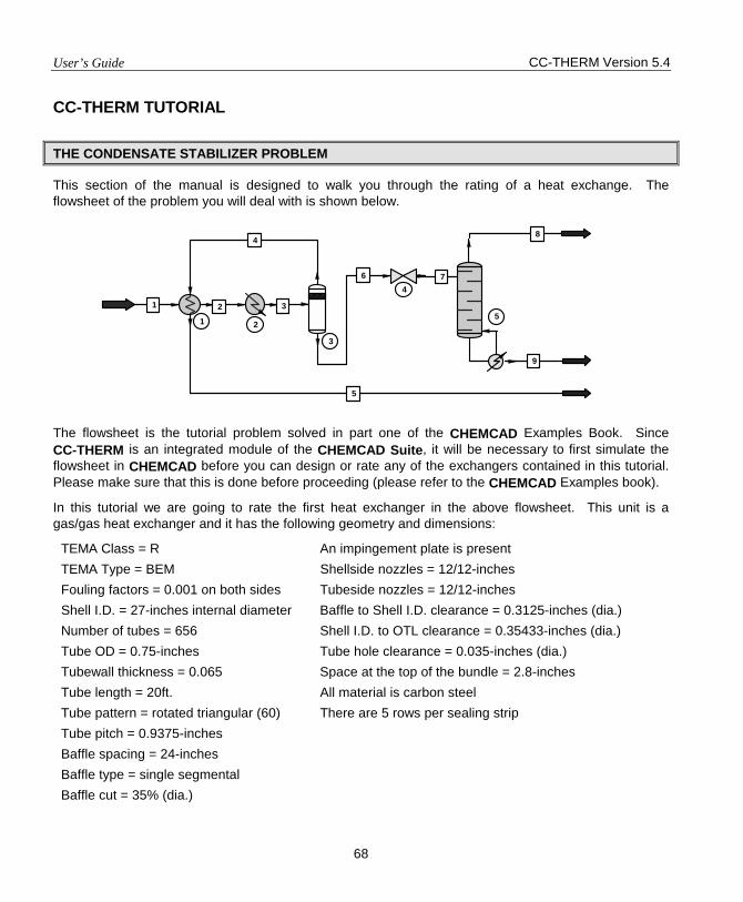
User’s Guide CC-THERM Version 5.4
68
CC-THERM TUTORIAL
THE CONDENSATE STABILIZER PROBLEM
This section of the manual is designed to walk you through the rating of a heat exchange. The flowsheet of the problem you will deal with is shown below.
The flowsheet is the tutorial problem solved in part one of the CHEMCAD Examples Book. Since CC-THERM is an integrated module of the CHEMCAD Suite, it will be necessary to first simulate the flowsheet in CHEMCAD before you can design or rate any of the exchangers contained in this tutorial. Please make sure that this is done before proceeding (please refer to the CHEMCAD Examples book).
In this tutorial we are going to rate the first heat exchanger in the above flowsheet. This unit is a gas/gas heat exchanger and it has the following geometry and dimensions:
TEMA Class = R An impingement plate is present TEMA Type = BEM Shellside nozzles = 12/12-inches Fouling factors = 0.001 on both sides Tubeside nozzles = 12/12-inches Shell I.D. = 27-inches internal diameter Baffle to Shell I.D. clearance = 0.3125-inches (dia.) Number of tubes = 656 Shell I.D. to OTL clearance = 0.35433-inches (dia.) Tube OD = 0.75-inches Tube hole clearance = 0.035-inches (dia.) Tubewall thickness = 0.065 Space at the top of the bundle = 2.8-inches Tube length = 20ft. All material is carbon steel Tube pattern = rotated triangular (60) There are 5 rows per sealing strip Tube pitch = 0.9375-inches Baffle spacing = 24-inches Baffle type = single segmental Baffle cut = 35% (dia.)
1 2
3
4
51 2 3
4
5
6 7
8
9
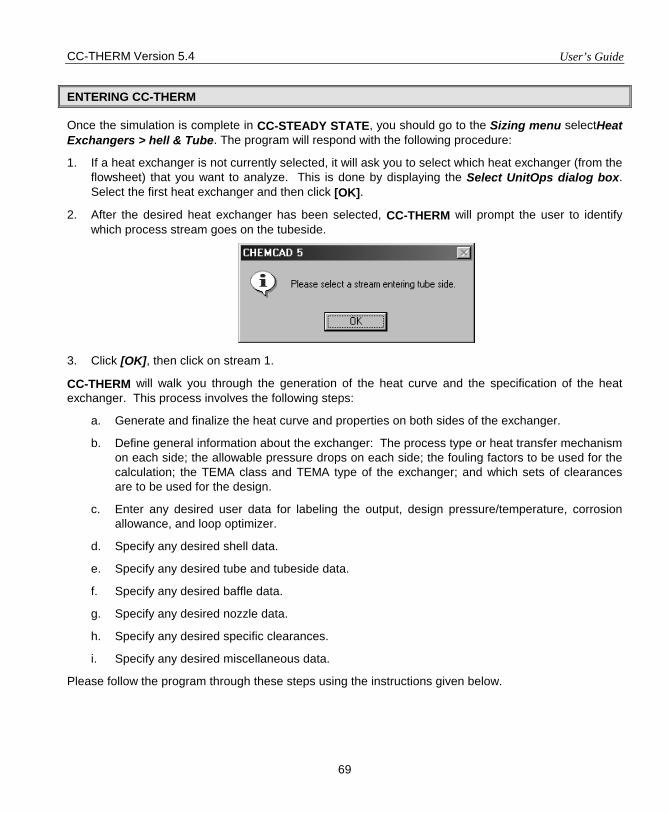
CC-THERM Version 5.4 User’s Guide
69
ENTERING CC-THERM
Once the simulation is complete in CC-STEADY STATE, you should go to the Sizing menu selectHeat Exchangers > hell & Tube. The program will respond with the following procedure:
1. If a heat exchanger is not currently selected, it will ask you to select which heat exchanger (from the flowsheet) that you want to analyze. This is done by displaying the Select UnitOps dialog box. Select the first heat exchanger and then click [OK].
2. After the desired heat exchanger has been selected, CC-THERM will prompt the user to identify which process stream goes on the tubeside.
3. Click [OK], then click on stream 1.
CC-THERM will walk you through the generation of the heat curve and the specification of the heat exchanger. This process involves the following steps:
a. Generate and finalize the heat curve and properties on both sides of the exchanger.
b. Define general information about the exchanger: The process type or heat transfer mechanism on each side; the allowable pressure drops on each side; the fouling factors to be used for the calculation; the TEMA class and TEMA type of the exchanger; and which sets of clearances are to be used for the design.
c. Enter any desired user data for labeling the output, design pressure/temperature, corrosion allowance, and loop optimizer.
d. Specify any desired shell data.
e. Specify any desired tube and tubeside data.
f. Specify any desired baffle data.
g. Specify any desired nozzle data.
h. Specify any desired specific clearances.
i. Specify any desired miscellaneous data.
Please follow the program through these steps using the instructions given below.
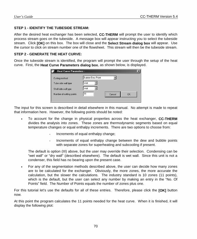
User’s Guide CC-THERM Version 5.4
70
STEP 1 - IDENTIFY THE TUBESIDE STREAM:
After the desired heat exchanger has been selected, CC-THERM will prompt the user to identify which process stream goes on the tubeside. A message box will appear instructing you to select the tubeside stream. Click [OK] on this box. The box will close and the Select Stream dialog box will appear. Use the cursor to click on stream number one of the flowsheet. This stream will then be the tubeside stream.
STEP 2 - GENERATE THE HEAT CURVE:
Once the tubeside stream is identified, the program will prompt the user through the setup of the heat curve. First, the Heat Curve Parameters dialog box, as shown below, is displayed.
The input for this screen is described in detail elsewhere in this manual. No attempt is made to repeat that information here. However, the following points should be noted:
• To account for the change in physical properties across the heat exchanger, CC-THERM divides the analysis into zones. These zones are thermodynamic segments based on equal temperature changes or equal enthalpy increments. There are two options to choose from:
- Increments of equal enthalpy change;
- Increments of equal enthalpy change between the dew and bubble points with separate zones for superheating and subcooling if present.
The default is option (III) above, but the user may override their selection. Condensing can be “wet wall” or “dry wall” (described elsewhere). The default is wet wall. Since this unit is not a condenser, this field has no bearing upon the present case.
• For any of the segmentation methods described above, the user can decide how many zones are to be calculated for the exchanger. Obviously, the more zones, the more accurate the calculation, but the slower the calculations. The industry standard is 10 zones (11 points), which is the default, but the user can select any number by making an entry in the “No. Of Points” field. The Number of Points equals the number of zones plus one.
For this tutorial let’s use the defaults for all of these entries. Therefore, please click the [OK] button now.
At this point the program calculates the 11 points needed for the heat curve. When it is finished, it will display the following plot:
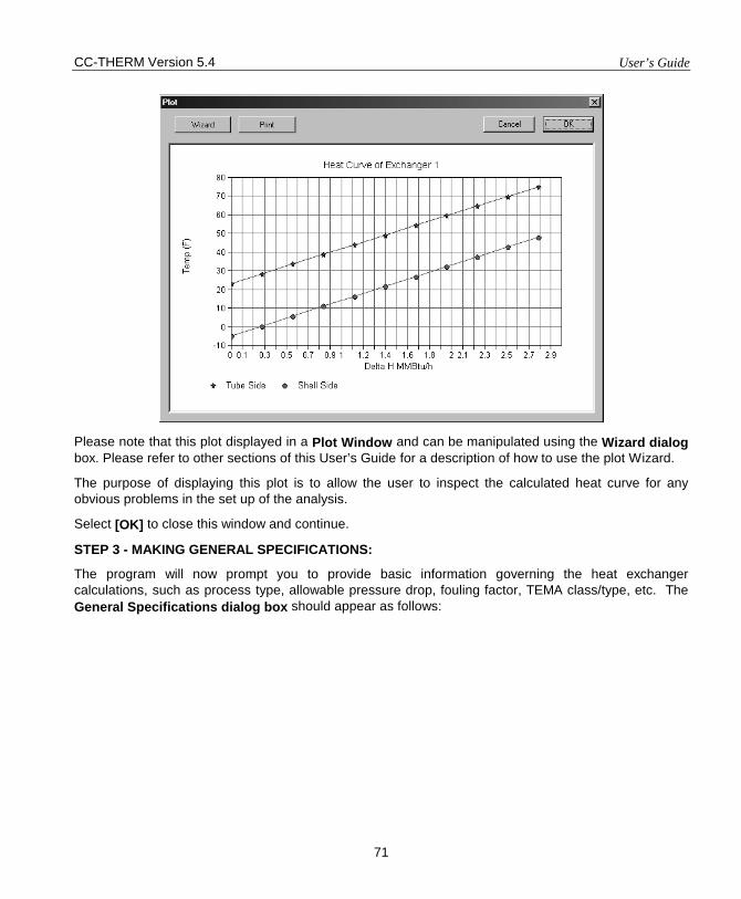
CC-THERM Version 5.4 User’s Guide
71
Please note that this plot displayed in a Plot Window and can be manipulated using the Wizard dialog box. Please refer to other sections of this User’s Guide for a description of how to use the plot Wizard.
The purpose of displaying this plot is to allow the user to inspect the calculated heat curve for any obvious problems in the set up of the analysis.
Select [OK] to close this window and continue.
STEP 3 - MAKING GENERAL SPECIFICATIONS:
The program will now prompt you to provide basic information governing the heat exchanger calculations, such as process type, allowable pressure drop, fouling factor, TEMA class/type, etc. The General Specifications dialog box should appear as follows:
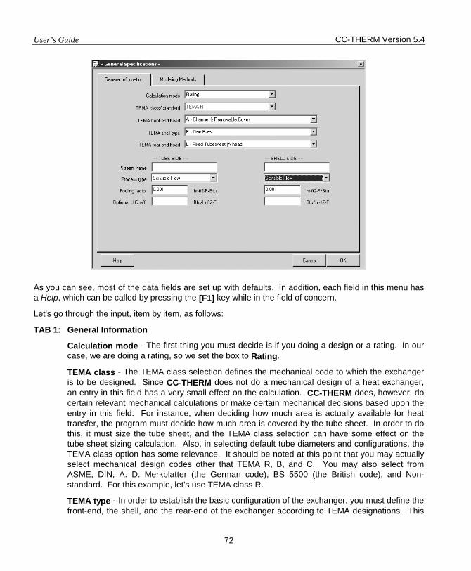
User’s Guide CC-THERM Version 5.4
72
As you can see, most of the data fields are set up with defaults. In addition, each field in this menu has a Help, which can be called by pressing the [F1] key while in the field of concern.
Let's go through the input, item by item, as follows:
TAB 1: General Information
Calculation mode - The first thing you must decide is if you doing a design or a rating. In our case, we are doing a rating, so we set the box to Rating.
TEMA class - The TEMA class selection defines the mechanical code to which the exchanger is to be designed. Since CC-THERM does not do a mechanical design of a heat exchanger, an entry in this field has a very small effect on the calculation. CC-THERM does, however, do certain relevant mechanical calculations or make certain mechanical decisions based upon the entry in this field. For instance, when deciding how much area is actually available for heat transfer, the program must decide how much area is covered by the tube sheet. In order to do this, it must size the tube sheet, and the TEMA class selection can have some effect on the tube sheet sizing calculation. Also, in selecting default tube diameters and configurations, the TEMA class option has some relevance. It should be noted at this point that you may actually select mechanical design codes other that TEMA R, B, and C. You may also select from ASME, DIN, A. D. Merkblatter (the German code), BS 5500 (the British code), and Non-standard. For this example, let's use TEMA class R.
TEMA type - In order to establish the basic configuration of the exchanger, you must define the front-end, the shell, and the rear-end of the exchanger according to TEMA designations. This
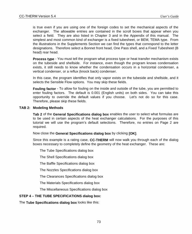
CC-THERM Version 5.4 User’s Guide
73
is true even if you are using one of the foreign codes to set the mechanical aspects of the exchanger. The allowable entries are contained in the scroll boxes that appear when you select a field. They are also listed in Chapter 3 and in the Appendix of this manual. The simplest and most common kind of exchanger is a fixed tubesheet, or BEM, TEMA type. From the illustrations in the Supplements Section we can find the types that correspond to the letter designations. Therefore select a Bonnet front head, One Pass shell, and a Fixed Tubesheet (B head) rear head.
Process type - You must tell the program what process type or heat transfer mechanism exists on the tubeside and shellside. For instance, even though the program knows condensation exists, it still needs to know whether the condensation occurs in a horizontal condenser, a vertical condenser, or a reflux (knock back) condenser.
In this case, the program identifies that only vapor exists on the tubeside and shellside, and it selects the Sensible Flow options. You may skip these fields.
Fouling factor - To allow for fouling on the inside and outside of the tube, you are permitted to enter fouling factors. The default is 0.001 (English units) on both sides. You can take this opportunity to override the default values if you choose. Let's not do so for this case. Therefore, please skip these fields.
TAB 2: Modeling Methods
Tab 2 of the General Specifications dialog box enables the user to select what formulas are to be used in certain aspects of the heat exchanger calculations. For the purposes of this tutorial we will use the program’s default selections. Therefore, no entries on Page 2 are required.
Now close the General Specifications dialog box by clicking [OK].
Since this example is a rating case, CC-THERM will now walk you through each of the dialog boxes necessary to completely define the geometry of the heat exchanger. These are:
The Tube Specifications dialog box
The Shell Specifications dialog box
The Baffle Specifications dialog box
The Nozzles Specifications dialog box
The Clearances Specifications dialog box
The Materials Specifications dialog box
The Miscellaneous Specifications dialog box
STEP 4 – THE TUBE SPECIFICATIONS dialog box:
The Tube Specifications dialog box looks like this:
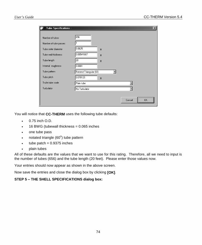
User’s Guide CC-THERM Version 5.4
74
You will notice that CC-THERM uses the following tube defaults:
• 0.75 inch O.D. • 16 BWG (tubewall thickness = 0.065 inches • one tube pass • notated triangle (60o) tube pattern • tube patch = 0.9375 inches • plain tubes
All of these defaults are the values that we want to use for this rating. Therefore, all we need to input is the number of tubes (656) and the tube length (20 feet). Please enter those values now.
Your entries should now appear as shown in the above screen.
Now save the entries and close the dialog box by clicking [OK].
STEP 5 – THE SHELL SPECIFICATIONS dialog box:
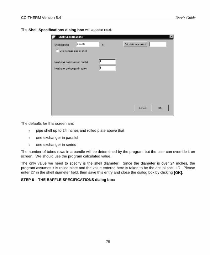
CC-THERM Version 5.4 User’s Guide
75
The Shell Specifications dialog box will appear next:
The defaults for this screen are:
• pipe shell up to 24 inches and rolled plate above that
• one exchanger in parallel
• one exchanger in series
The number of tubes rows in a bundle will be determined by the program but the user can override it on screen. We should use the program calculated value.
The only value we need to specify is the shell diameter. Since the diameter is over 24 inches, the program assumes it is rolled plate and the value entered here is taken to be the actual shell I.D. Please enter 27 in the shell diameter field, then save this entry and close the dialog box by clicking [OK].
STEP 6 – THE BAFFLE SPECIFICATIONS dialog box:
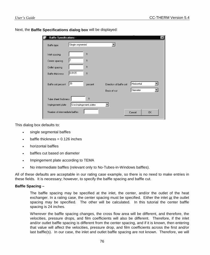
User’s Guide CC-THERM Version 5.4
76
Next, the Baffle Specifications dialog box will be displayed:
This dialog box defaults to:
• single segmental baffles
• baffle thickness = 0.126 inches
• horizontal baffles
• baffles cut based on diameter
• Impingement plate according to TEMA
• No intermediate baffles (relevant only to No-Tubes-in-Windows baffles).
All of these defaults are acceptable in our rating case example, so there is no need to make entries in these fields. It is necessary; however, to specify the baffle spacing and baffle cut.
Baffle Spacing –
The baffle spacing may be specified at the inlet, the center, and/or the outlet of the heat exchanger. In a rating case, the center spacing must be specified. Either the inlet or the outlet spacing may be specified. The other will be calculated. In this tutorial the center baffle spacing is 24 inches.
Wherever the baffle spacing changes, the cross flow area will be different, and therefore, the velocities, pressure drops, and film coefficients will also be different. Therefore, if the inlet and/or outlet baffle spacing is different from the center spacing, and if it is known, then entering that value will affect the velocities, pressure drop, and film coefficients across the first and/or last baffle(s). In our case, the inlet and outlet baffle spacing are not known. Therefore, we will
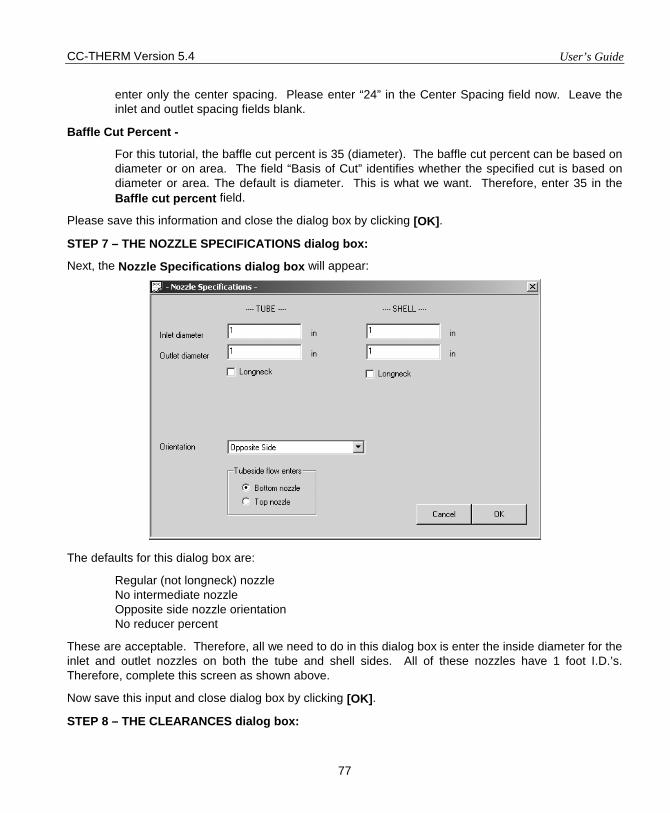
CC-THERM Version 5.4 User’s Guide
77
enter only the center spacing. Please enter “24” in the Center Spacing field now. Leave the inlet and outlet spacing fields blank.
Baffle Cut Percent -
For this tutorial, the baffle cut percent is 35 (diameter). The baffle cut percent can be based on diameter or on area. The field “Basis of Cut” identifies whether the specified cut is based on diameter or area. The default is diameter. This is what we want. Therefore, enter 35 in the Baffle cut percent field.
Please save this information and close the dialog box by clicking [OK].
STEP 7 – THE NOZZLE SPECIFICATIONS dialog box:
Next, the Nozzle Specifications dialog box will appear:
The defaults for this dialog box are:
Regular (not longneck) nozzle No intermediate nozzle Opposite side nozzle orientation No reducer percent
These are acceptable. Therefore, all we need to do in this dialog box is enter the inside diameter for the inlet and outlet nozzles on both the tube and shell sides. All of these nozzles have 1 foot I.D.’s. Therefore, complete this screen as shown above.
Now save this input and close dialog box by clicking [OK].
STEP 8 – THE CLEARANCES dialog box:
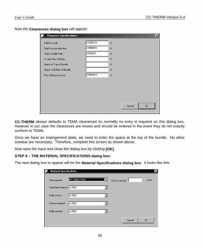
User’s Guide CC-THERM Version 5.4
78
Now the Clearances dialog box will appear:
CC-THERM always defaults to TEMA clearances so normally no entry is required on this dialog box. However in our case the clearances are known and should be entered in the event they do not exactly conform to TEMA.
Once we have an impingement plate, we need to enter the space at the top of the bundle. No other outwear are necessary. Therefore, complete this screen as shown above.
Now save the input and close the dialog box by clicking [OK].
STEP 9 – THE MATERIAL SPECIFICATIONS dialog box:
The next dialog box to appear will be the Material Specifications dialog box. It looks like this:

CC-THERM Version 5.4 User’s Guide
79
The purpose of this dialog box is to allow the user to specify the Materials of construction for the heat exchanger. Only the tube material and the tubesheet material have any impact on the thermal analysis. Entries in the other fields are only used to fill out the TEMA sheet.
The default for all materials is carbon steel. This is acceptable in this case, so no entries are necessary.
Please close this dialog box by clicking [OK].
STEP 10 – THE MISCELLANEOUS SPECIFICATIONS dialog box:
The last dialog box to appear will be the Miscellaneous Specifications dialog box. It looks like this:
The only field on this screen which we are concerned about is the “Rows per Sealing Strip” field. We want 5 rows per sealing strip, and this is the default. Therefore, no entries are required on this screen.
Close this dialog box by clicking [OK].
THE CC-THERM MENU:
The input sequence for our rating case is now complete. The program will now open the Shell and Tube Exchanger Menu, which looks like this:
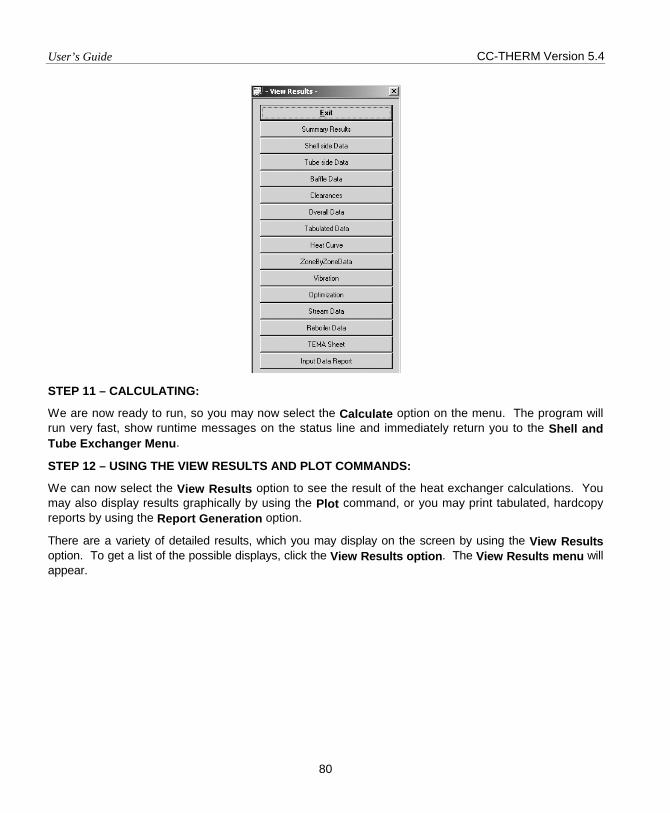
User’s Guide CC-THERM Version 5.4
80
STEP 11 – CALCULATING:
We are now ready to run, so you may now select the Calculate option on the menu. The program will run very fast, show runtime messages on the status line and immediately return you to the Shell and Tube Exchanger Menu.
STEP 12 – USING THE VIEW RESULTS AND PLOT COMMANDS:
We can now select the View Results option to see the result of the heat exchanger calculations. You may also display results graphically by using the Plot command, or you may print tabulated, hardcopy reports by using the Report Generation option.
There are a variety of detailed results, which you may display on the screen by using the View Results option. To get a list of the possible displays, click the View Results option. The View Results menu will appear.
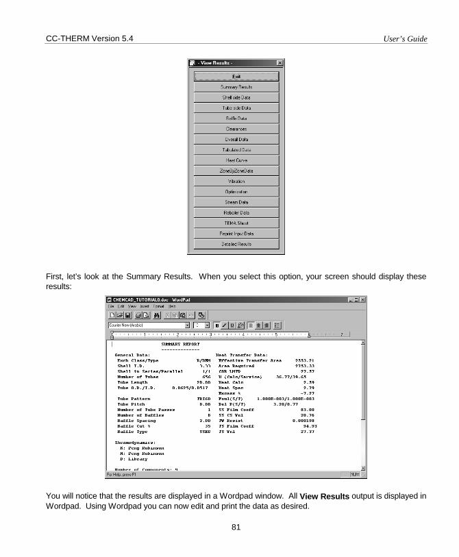
CC-THERM Version 5.4 User’s Guide
81
First, let’s look at the Summary Results. When you select this option, your screen should display these results:
You will notice that the results are displayed in a Wordpad window. All View Results output is displayed in Wordpad. Using Wordpad you can now edit and print the data as desired.
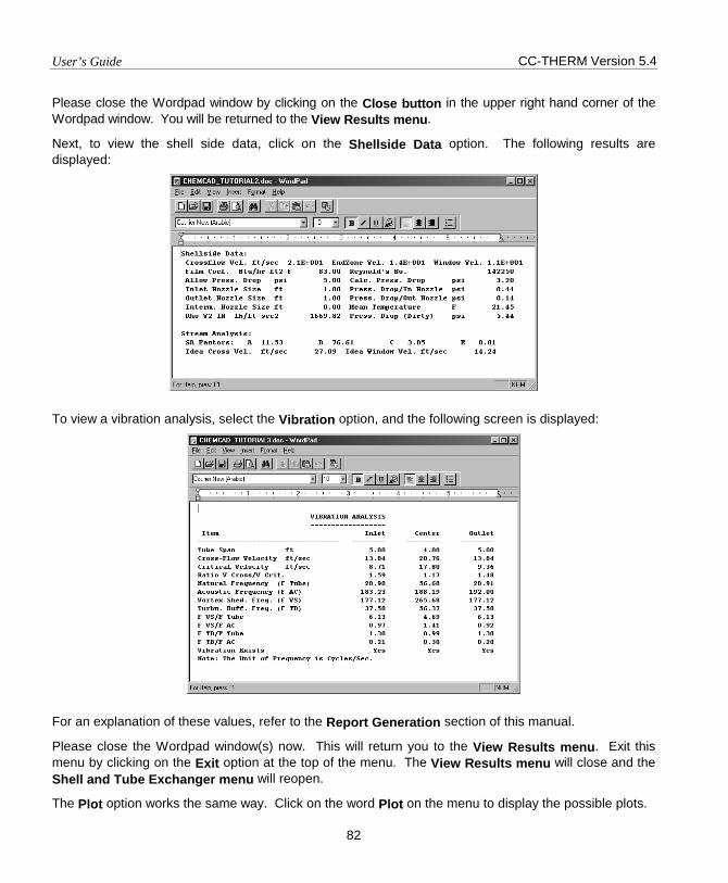
User’s Guide CC-THERM Version 5.4
82
Please close the Wordpad window by clicking on the Close button in the upper right hand corner of the Wordpad window. You will be returned to the View Results menu.
Next, to view the shell side data, click on the Shellside Data option. The following results are displayed:
To view a vibration analysis, select the Vibration option, and the following screen is displayed:
For an explanation of these values, refer to the Report Generation section of this manual.
Please close the Wordpad window(s) now. This will return you to the View Results menu. Exit this menu by clicking on the Exit option at the top of the menu. The View Results menu will close and the Shell and Tube Exchanger menu will reopen.
The Plot option works the same way. Click on the word Plot on the menu to display the possible plots.
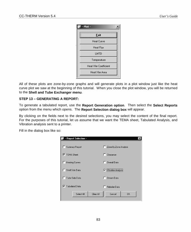
CC-THERM Version 5.4 User’s Guide
83
All of these plots are zone-by-zone graphs and will generate plots in a plot window just like the heat curve plot we saw at the beginning of this tutorial. When you close the plot window, you will be returned to the Shell and Tube Exchanger menu.
STEP 13 – GENERATING A REPORT:
To generate a tabulated report, use the Report Generation option. Then select the Select Reports option from the menu which opens. The Report Selection dialog box will appear.
By clicking on the fields next to the desired selections, you may select the content of the final report. For the purposes of this tutorial, let us assume that we want the TEMA sheet, Tabulated Analysis, and Vibration analysis sent to a printer.
Fill in the dialog box like so:

User’s Guide CC-THERM Version 5.4
84
Now click [OK] to save. The dialog box will close and the Report Generation menu will reopen.
Now select the Generate Reports option. This will cause the program to make the report and display it for you. It will be displayed in a Wordpad window as before. You now have the option of browsing, editing, and/or printing it using Wordpad commands.
We have now completed all of the exercises for our tutorial. To exit CC-THERM;
Close the Wordpad window. You will be returned to the Report Generation menu.
Click on the Exit command on the Report Generation menu. The Shell and Tube Exchanger menu will open. Click on the Exit command on the Shell and Tube Exchanger menu.
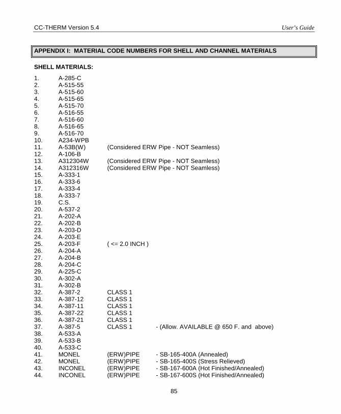
CC-THERM Version 5.4 User’s Guide
85
APPENDIX I: MATERIAL CODE NUMBERS FOR SHELL AND CHANNEL MATERIALS
SHELL MATERIALS:
1. A-285-C 2. A-515-55 3. A-515-60 4. A-515-65 5. A-515-70 6. A-516-55 7. A-516-60 8. A-516-65 9. A-516-70 10. A234-WPB 11. A-53B(W) (Considered ERW Pipe - NOT Seamless) 12. A-106-B 13. A312304W (Considered ERW Pipe - NOT Seamless) 14. A312316W (Considered ERW Pipe - NOT Seamless) 15. A-333-1 16. A-333-6 17. A-333-4 18. A-333-7 19. C.S. 20. A-537-2 21. A-202-A 22. A-202-B 23. A-203-D 24. A-203-E 25. A-203-F ( <= 2.0 INCH ) 26. A-204-A 27. A-204-B 28. A-204-C 29. A-225-C 30. A-302-A 31. A-302-B 32. A-387-2 CLASS 1 33. A-387-12 CLASS 1 34. A-387-11 CLASS 1 35. A-387-22 CLASS 1 36. A-387-21 CLASS 1 37. A-387-5 CLASS 1 - (Allow. AVAILABLE @ 650 F. and above) 38. A-533-A 39. A-533-B 40. A-533-C 41. MONEL (ERW)PIPE - SB-165-400A (Annealed) 42. MONEL (ERW)PIPE - SB-165-400S (Stress Relieved) 43. INCONEL (ERW)PIPE - SB-167-600A (Hot Finished/Annealed) 44. INCONEL (ERW)PIPE - SB-167-600S (Hot Finished/Annealed)
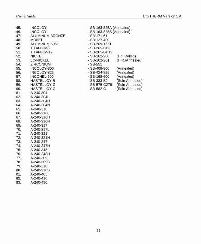
User’s Guide CC-THERM Version 5.4
86
45. INCOLOY - SB-163-825A (Annealed) 46. INCOLOY - SB-163-825S (Annealed) 47. ALUMINUM BRONZE - SB-171-61 48. MONEL - SB-127-400 49. ALUMINUM-6061 - SB-209-T651 50. TITANIUM-2 - SB-265-Gr 2 51. TITANIUM-12 - SB-265-Gr 12 52. NICKEL - SB-162-200 (Hot Rolled) 53. LC-NICKEL - SB-162-201 (H.R./Annealed) 54. ZIRCONIUM - SB-551 55. INCOLOY-800 - SB-409-800 (Annealed) 56. INCOLOY-825 - SB-424-825 (Annealed) 57. INCONEL-600 - SB-168-600 (Annealed) 58. HASTELLOY-B - SB-333-B2 (Soln Annealed) 59. HASTELLOY-C - SB-575-C276 (Soln Annealed) 60. HASTELLOY-G - SB-582-G (Soln Annealed) 61. A-240-304 62. A-240-304L 63. A-240-304H 64. A-240-304N 65. A-240-316 66. A-240-316L 67. A-240-316H 68. A-240-316N 69. A-240-317 70. A-240-317L 71. A-240-321 72. A-240-321H 73. A-240-347 74. A-240-347H 75. A-240-348 76. A-240-348H 77. A-240-309 78. A-240-309S 79. A-240-310 80. A-240-310S 81. A-240-405 82. A-240-410 83. A-240-430
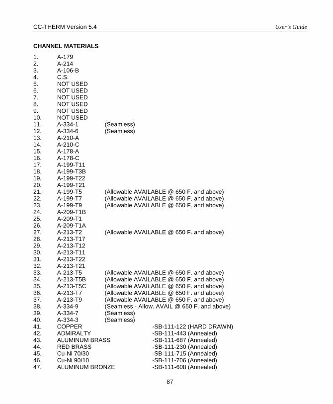
CC-THERM Version 5.4 User’s Guide
87
CHANNEL MATERIALS
1. A-179 2. A-214 3. A-106-B 4. C.S. 5. NOT USED 6. NOT USED 7. NOT USED 8. NOT USED 9. NOT USED 10. NOT USED 11. A-334-1 (Seamless) 12. A-334-6 (Seamless) 13. A-210-A 14. A-210-C 15. A-178-A 16. A-178-C 17. A-199-T11 18. A-199-T3B 19. A-199-T22 20. A-199-T21 21. A-199-T5 (Allowable AVAILABLE @ 650 F. and above) 22. A-199-T7 (Allowable AVAILABLE @ 650 F. and above) 23. A-199-T9 (Allowable AVAILABLE @ 650 F. and above) 24. A-209-T1B 25. A-209-T1 26. A-209-T1A 27. A-213-T2 (Allowable AVAILABLE @ 650 F. and above) 28. A-213-T17 29. A-213-T12 30. A-213-T11 31. A-213-T22 32. A-213-T21 33. A-213-T5 (Allowable AVAILABLE @ 650 F. and above) 34. A-213-T5B (Allowable AVAILABLE @ 650 F. and above) 35. A-213-T5C (Allowable AVAILABLE @ 650 F. and above) 36. A-213-T7 (Allowable AVAILABLE @ 650 F. and above) 37. A-213-T9 (Allowable AVAILABLE @ 650 F. and above) 38. A-334-9 (Seamless - Allow. AVAIL @ 650 F. and above) 39. A-334-7 (Seamless) 40. A-334-3 (Seamless) 41. COPPER -SB-111-122 (HARD DRAWN) 42. ADMIRALTY -SB-111-443 (Annealed) 43. ALUMINUM BRASS -SB-111-687 (Annealed) 44. RED BRASS -SB-111-230 (Annealed) 45. Cu-Ni 70/30 -SB-111-715 (Annealed) 46. Cu-Ni 90/10 -SB-111-706 (Annealed) 47. ALUMINUM BRONZE -SB-111-608 (Annealed)
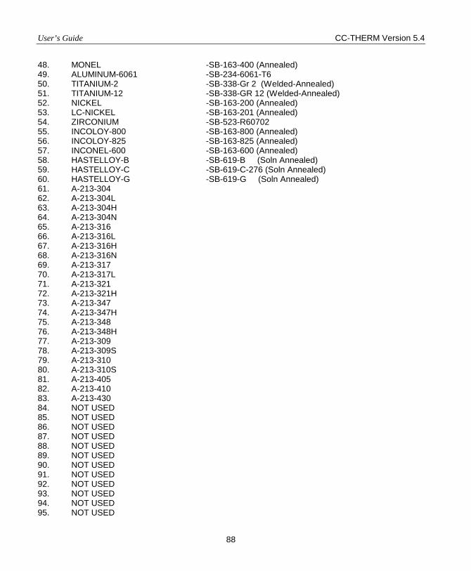
User’s Guide CC-THERM Version 5.4
88
48. MONEL -SB-163-400 (Annealed) 49. ALUMINUM-6061 -SB-234-6061-T6 50. TITANIUM-2 -SB-338-Gr 2 (Welded-Annealed) 51. TITANIUM-12 -SB-338-GR 12 (Welded-Annealed) 52. NICKEL -SB-163-200 (Annealed) 53. LC-NICKEL -SB-163-201 (Annealed) 54. ZIRCONIUM -SB-523-R60702 55. INCOLOY-800 -SB-163-800 (Annealed) 56. INCOLOY-825 -SB-163-825 (Annealed) 57. INCONEL-600 -SB-163-600 (Annealed) 58. HASTELLOY-B -SB-619-B (Soln Annealed) 59. HASTELLOY-C -SB-619-C-276 (Soln Annealed) 60. HASTELLOY-G -SB-619-G (Soln Annealed) 61. A-213-304 62. A-213-304L 63. A-213-304H 64. A-213-304N 65. A-213-316 66. A-213-316L 67. A-213-316H 68. A-213-316N 69. A-213-317 70. A-213-317L 71. A-213-321 72. A-213-321H 73. A-213-347 74. A-213-347H 75. A-213-348 76. A-213-348H 77. A-213-309 78. A-213-309S 79. A-213-310 80. A-213-310S 81. A-213-405 82. A-213-410 83. A-213-430 84. NOT USED 85. NOT USED 86. NOT USED 87. NOT USED 88. NOT USED 89. NOT USED 90. NOT USED 91. NOT USED 92. NOT USED 93. NOT USED 94. NOT USED 95. NOT USED
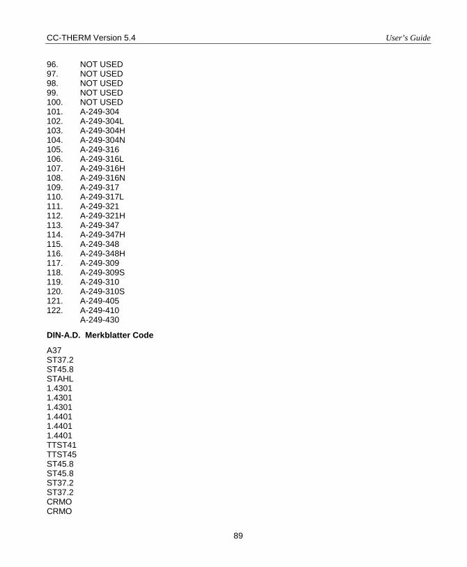
CC-THERM Version 5.4 User’s Guide
89
96. NOT USED 97. NOT USED 98. NOT USED 99. NOT USED 100. NOT USED 101. A-249-304 102. A-249-304L 103. A-249-304H 104. A-249-304N 105. A-249-316 106. A-249-316L 107. A-249-316H 108. A-249-316N 109. A-249-317 110. A-249-317L 111. A-249-321 112. A-249-321H 113. A-249-347 114. A-249-347H 115. A-249-348 116. A-249-348H 117. A-249-309 118. A-249-309S 119. A-249-310 120. A-249-310S 121. A-249-405 122. A-249-410
A-249-430
DIN-A.D. Merkblatter Code
A37 ST37.2 ST45.8 STAHL 1.4301 1.4301 1.4301 1.4401 1.4401 1.4401 TTST41 TTST45 ST45.8 ST45.8 ST37.2 ST37.2 CRMO CRMO
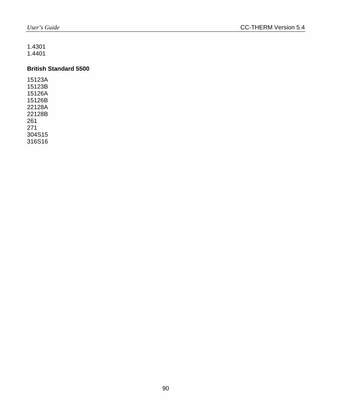
User’s Guide CC-THERM Version 5.4
90
1.4301 1.4401
British Standard 5500
15123A 15123B 15126A 15126B 22128A 22128B 261 271 304S15 316S16
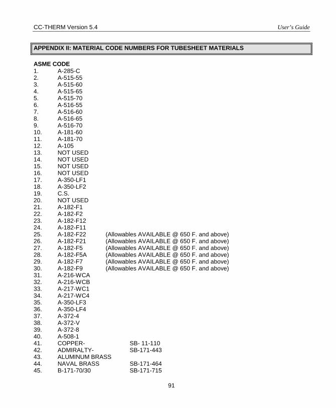
CC-THERM Version 5.4 User’s Guide
91
APPENDIX II: MATERIAL CODE NUMBERS FOR TUBESHEET MATERIALS
ASME CODE 1. A-285-C 2. A-515-55 3. A-515-60 4. A-515-65 5. A-515-70 6. A-516-55 7. A-516-60 8. A-516-65 9. A-516-70 10. A-181-60 11. A-181-70 12. A-105 13. NOT USED 14. NOT USED 15. NOT USED 16. NOT USED 17. A-350-LF1 18. A-350-LF2 19. C.S. 20. NOT USED 21. A-182-F1 22. A-182-F2 23. A-182-F12 24. A-182-F11 25. A-182-F22 (Allowables AVAILABLE @ 650 F. and above) 26. A-182-F21 (Allowables AVAILABLE @ 650 F. and above) 27. A-182-F5 (Allowables AVAILABLE @ 650 F. and above) 28. A-182-F5A (Allowables AVAILABLE @ 650 F. and above) 29. A-182-F7 (Allowables AVAILABLE @ 650 F. and above) 30. A-182-F9 (Allowables AVAILABLE @ 650 F. and above) 31. A-216-WCA 32. A-216-WCB 33. A-217-WC1 34. A-217-WC4 35. A-350-LF3 36. A-350-LF4 37. A-372-4 38. A-372-V 39. A-372-8 40. A-508-1 41. COPPER- SB- 11-110 42. ADMIRALTY- SB-171-443 43. ALUMINUM BRASS 44. NAVAL BRASS SB-171-464 45. B-171-70/30 SB-171-715
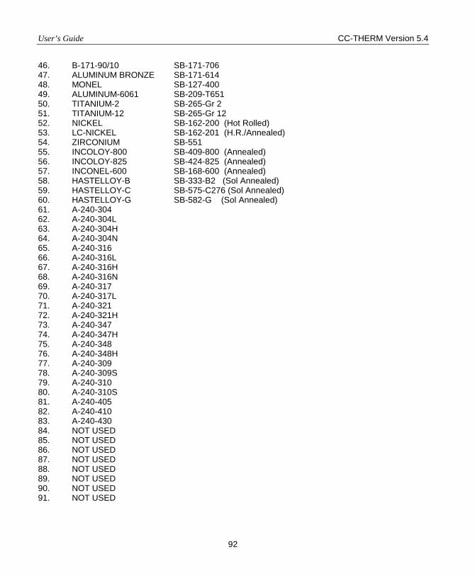
User’s Guide CC-THERM Version 5.4
92
46. B-171-90/10 SB-171-706 47. ALUMINUM BRONZE SB-171-614 48. MONEL SB-127-400 49. ALUMINUM-6061 SB-209-T651 50. TITANIUM-2 SB-265-Gr 2 51. TITANIUM-12 SB-265-Gr 12 52. NICKEL SB-162-200 (Hot Rolled) 53. LC-NICKEL SB-162-201 (H.R./Annealed) 54. ZIRCONIUM SB-551 55. INCOLOY-800 SB-409-800 (Annealed) 56. INCOLOY-825 SB-424-825 (Annealed) 57. INCONEL-600 SB-168-600 (Annealed) 58. HASTELLOY-B SB-333-B2 (Sol Annealed) 59. HASTELLOY-C SB-575-C276 (Sol Annealed) 60. HASTELLOY-G SB-582-G (Sol Annealed) 61. A-240-304 62. A-240-304L 63. A-240-304H 64. A-240-304N 65. A-240-316 66. A-240-316L 67. A-240-316H 68. A-240-316N 69. A-240-317 70. A-240-317L 71. A-240-321 72. A-240-321H 73. A-240-347 74. A-240-347H 75. A-240-348 76. A-240-348H 77. A-240-309 78. A-240-309S 79. A-240-310 80. A-240-310S 81. A-240-405 82. A-240-410 83. A-240-430 84. NOT USED 85. NOT USED 86. NOT USED 87. NOT USED 88. NOT USED 89. NOT USED 90. NOT USED 91. NOT USED
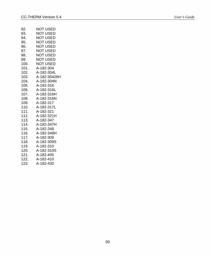
CC-THERM Version 5.4 User’s Guide
93
92. NOT USED 93. NOT USED 94. NOT USED 95. NOT USED 96. NOT USED 97. NOT USED 98. NOT USED 99. NOT USED 100. NOT USED 101. A-182-304 102. A-182-304L 103. A-182-30426H 104. A-182-304N 105. A-182-316 106. A-182-316L 107. A-182-316H 108. A-182-316N 109. A-182-317 110. A-182-317L 111. A-182-321 112. A-182-321H 113. A-182-347 114. A-182-347H 115. A-182-348 116. A-182-348H 117. A-182-309 118. A-182-309S 119. A-182-310 120. A-182-310S 121. A-182-405 122. A-182-410 123. A-182-430
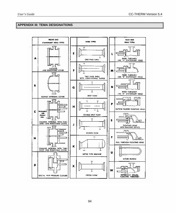
User’s Guide CC-THERM Version 5.4
94
APPENDIX III: TEMA DESIGNATIONS
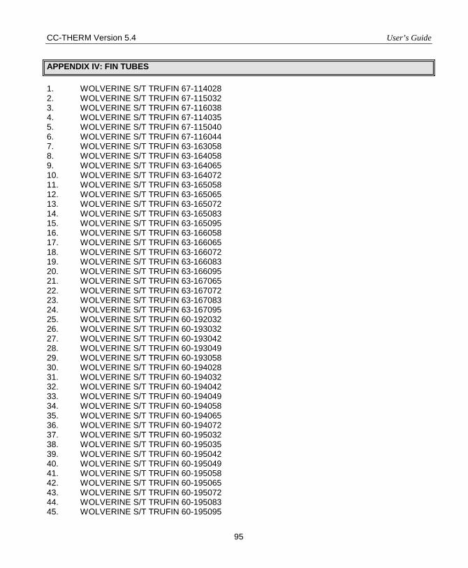
CC-THERM Version 5.4 User’s Guide
95
APPENDIX IV: FIN TUBES
1. WOLVERINE S/T TRUFIN 67-114028 2. WOLVERINE S/T TRUFIN 67-115032 3. WOLVERINE S/T TRUFIN 67-116038 4. WOLVERINE S/T TRUFIN 67-114035 5. WOLVERINE S/T TRUFIN 67-115040 6. WOLVERINE S/T TRUFIN 67-116044 7. WOLVERINE S/T TRUFIN 63-163058 8. WOLVERINE S/T TRUFIN 63-164058 9. WOLVERINE S/T TRUFIN 63-164065 10. WOLVERINE S/T TRUFIN 63-164072 11. WOLVERINE S/T TRUFIN 63-165058 12. WOLVERINE S/T TRUFIN 63-165065 13. WOLVERINE S/T TRUFIN 63-165072 14. WOLVERINE S/T TRUFIN 63-165083 15. WOLVERINE S/T TRUFIN 63-165095 16. WOLVERINE S/T TRUFIN 63-166058 17. WOLVERINE S/T TRUFIN 63-166065 18. WOLVERINE S/T TRUFIN 63-166072 19. WOLVERINE S/T TRUFIN 63-166083 20. WOLVERINE S/T TRUFIN 63-166095 21. WOLVERINE S/T TRUFIN 63-167065 22. WOLVERINE S/T TRUFIN 63-167072 23. WOLVERINE S/T TRUFIN 63-167083 24. WOLVERINE S/T TRUFIN 63-167095 25. WOLVERINE S/T TRUFIN 60-192032 26. WOLVERINE S/T TRUFIN 60-193032 27. WOLVERINE S/T TRUFIN 60-193042 28. WOLVERINE S/T TRUFIN 60-193049 29. WOLVERINE S/T TRUFIN 60-193058 30. WOLVERINE S/T TRUFIN 60-194028 31. WOLVERINE S/T TRUFIN 60-194032 32. WOLVERINE S/T TRUFIN 60-194042 33. WOLVERINE S/T TRUFIN 60-194049 34. WOLVERINE S/T TRUFIN 60-194058 35. WOLVERINE S/T TRUFIN 60-194065 36. WOLVERINE S/T TRUFIN 60-194072 37. WOLVERINE S/T TRUFIN 60-195032 38. WOLVERINE S/T TRUFIN 60-195035 39. WOLVERINE S/T TRUFIN 60-195042 40. WOLVERINE S/T TRUFIN 60-195049 41. WOLVERINE S/T TRUFIN 60-195058 42. WOLVERINE S/T TRUFIN 60-195065 43. WOLVERINE S/T TRUFIN 60-195072 44. WOLVERINE S/T TRUFIN 60-195083 45. WOLVERINE S/T TRUFIN 60-195095
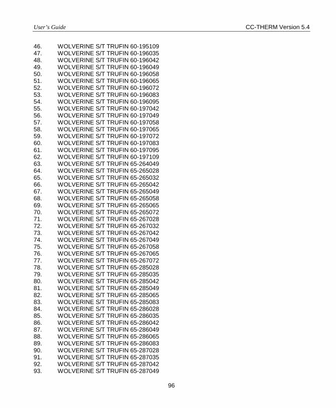
User’s Guide CC-THERM Version 5.4
96
46. WOLVERINE S/T TRUFIN 60-195109 47. WOLVERINE S/T TRUFIN 60-196035 48. WOLVERINE S/T TRUFIN 60-196042 49. WOLVERINE S/T TRUFIN 60-196049 50. WOLVERINE S/T TRUFIN 60-196058 51. WOLVERINE S/T TRUFIN 60-196065 52. WOLVERINE S/T TRUFIN 60-196072 53. WOLVERINE S/T TRUFIN 60-196083 54. WOLVERINE S/T TRUFIN 60-196095 55. WOLVERINE S/T TRUFIN 60-197042 56. WOLVERINE S/T TRUFIN 60-197049 57. WOLVERINE S/T TRUFIN 60-197058 58. WOLVERINE S/T TRUFIN 60-197065 59. WOLVERINE S/T TRUFIN 60-197072 60. WOLVERINE S/T TRUFIN 60-197083 61. WOLVERINE S/T TRUFIN 60-197095 62. WOLVERINE S/T TRUFIN 60-197109 63. WOLVERINE S/T TRUFIN 65-264049 64. WOLVERINE S/T TRUFIN 65-265028 65. WOLVERINE S/T TRUFIN 65-265032 66. WOLVERINE S/T TRUFIN 65-265042 67. WOLVERINE S/T TRUFIN 65-265049 68. WOLVERINE S/T TRUFIN 65-265058 69. WOLVERINE S/T TRUFIN 65-265065 70. WOLVERINE S/T TRUFIN 65-265072 71. WOLVERINE S/T TRUFIN 65-267028 72. WOLVERINE S/T TRUFIN 65-267032 73. WOLVERINE S/T TRUFIN 65-267042 74. WOLVERINE S/T TRUFIN 65-267049 75. WOLVERINE S/T TRUFIN 65-267058 76. WOLVERINE S/T TRUFIN 65-267065 77. WOLVERINE S/T TRUFIN 65-267072 78. WOLVERINE S/T TRUFIN 65-285028 79. WOLVERINE S/T TRUFIN 65-285035 80. WOLVERINE S/T TRUFIN 65-285042 81. WOLVERINE S/T TRUFIN 65-285049 82. WOLVERINE S/T TRUFIN 65-285065 83. WOLVERINE S/T TRUFIN 65-285083 84. WOLVERINE S/T TRUFIN 65-286028 85. WOLVERINE S/T TRUFIN 65-286035 86. WOLVERINE S/T TRUFIN 65-286042 87. WOLVERINE S/T TRUFIN 65-286049 88. WOLVERINE S/T TRUFIN 65-286065 89. WOLVERINE S/T TRUFIN 65-286083 90. WOLVERINE S/T TRUFIN 65-287028 91. WOLVERINE S/T TRUFIN 65-287035 92. WOLVERINE S/T TRUFIN 65-287042 93. WOLVERINE S/T TRUFIN 65-287049
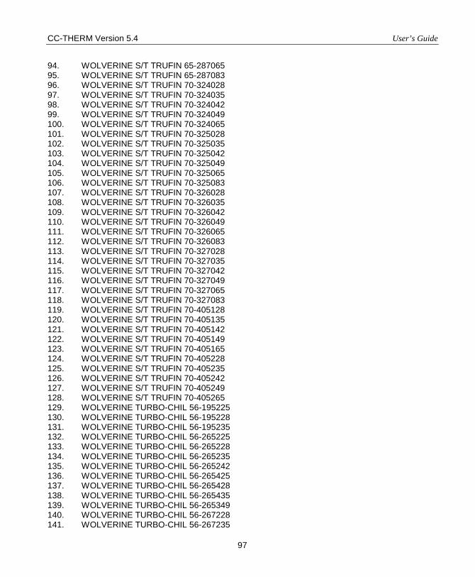
CC-THERM Version 5.4 User’s Guide
97
94. WOLVERINE S/T TRUFIN 65-287065 95. WOLVERINE S/T TRUFIN 65-287083 96. WOLVERINE S/T TRUFIN 70-324028 97. WOLVERINE S/T TRUFIN 70-324035 98. WOLVERINE S/T TRUFIN 70-324042 99. WOLVERINE S/T TRUFIN 70-324049 100. WOLVERINE S/T TRUFIN 70-324065 101. WOLVERINE S/T TRUFIN 70-325028 102. WOLVERINE S/T TRUFIN 70-325035 103. WOLVERINE S/T TRUFIN 70-325042 104. WOLVERINE S/T TRUFIN 70-325049 105. WOLVERINE S/T TRUFIN 70-325065 106. WOLVERINE S/T TRUFIN 70-325083 107. WOLVERINE S/T TRUFIN 70-326028 108. WOLVERINE S/T TRUFIN 70-326035 109. WOLVERINE S/T TRUFIN 70-326042 110. WOLVERINE S/T TRUFIN 70-326049 111. WOLVERINE S/T TRUFIN 70-326065 112. WOLVERINE S/T TRUFIN 70-326083 113. WOLVERINE S/T TRUFIN 70-327028 114. WOLVERINE S/T TRUFIN 70-327035 115. WOLVERINE S/T TRUFIN 70-327042 116. WOLVERINE S/T TRUFIN 70-327049 117. WOLVERINE S/T TRUFIN 70-327065 118. WOLVERINE S/T TRUFIN 70-327083 119. WOLVERINE S/T TRUFIN 70-405128 120. WOLVERINE S/T TRUFIN 70-405135 121. WOLVERINE S/T TRUFIN 70-405142 122. WOLVERINE S/T TRUFIN 70-405149 123. WOLVERINE S/T TRUFIN 70-405165 124. WOLVERINE S/T TRUFIN 70-405228 125. WOLVERINE S/T TRUFIN 70-405235 126. WOLVERINE S/T TRUFIN 70-405242 127. WOLVERINE S/T TRUFIN 70-405249 128. WOLVERINE S/T TRUFIN 70-405265 129. WOLVERINE TURBO-CHIL 56-195225 130. WOLVERINE TURBO-CHIL 56-195228 131. WOLVERINE TURBO-CHIL 56-195235 132. WOLVERINE TURBO-CHIL 56-265225 133. WOLVERINE TURBO-CHIL 56-265228 134. WOLVERINE TURBO-CHIL 56-265235 135. WOLVERINE TURBO-CHIL 56-265242 136. WOLVERINE TURBO-CHIL 56-265425 137. WOLVERINE TURBO-CHIL 56-265428 138. WOLVERINE TURBO-CHIL 56-265435 139. WOLVERINE TURBO-CHIL 56-265349 140. WOLVERINE TURBO-CHIL 56-267228 141. WOLVERINE TURBO-CHIL 56-267235
User’s Guide CC-THERM Version 5.4
98
142. WOLVERINE TURBO-CHIL 56-285628 143. WOLVERINE TURBO-CHIL 56-285635 144. WOLVERINE TURBO-CHIL 56-325525 145. WOLVERINE TURBO-CHIL 56-325528 146. WOLVERINE TURBO-CHIL 56-405228 147. WOLVERINE TURBO-CHIL 56-405235 148. WOLVERINE TURBO-CHIL 56-405425 149. WOLVERINE TURBO-CHIL 56-405428 150. WOLVERINE TURBO-CHIL 56-405435 151. WOLVERINE KORODENS MHT 57-1035 152. WOLVERINE KORODENS MHT 57-1042 153. WOLVERINE KORODENS MHT 57-1049 154. WOLVERINE KORODENS MHT 57-1065 155. WOLVERINE KORODENS MHT 57-1235 156. WOLVERINE KORODENS MHT 57-1242 157. WOLVERINE KORODENS MHT 57-1249 158. WOLVERINE KORODENS MHT 57-1265 159. WOLVERINE KORODENS MHT 57-1435 160. WOLVERINE KORODENS MHT 57-1442 161. WOLVERINE KORODENS MHT 57-1449 162. WOLVERINE KORODENS MHT 57-1465 163. WOLVERINE KORODENS MHT 57-1635 164. WOLVERINE KORODENS MHT 57-1642 165. WOLVERINE KORODENS MHT 57-1649 166. WOLVERINE KORODENS MHT 57-1665 167. WOLVERINE KORODENS MHT 57-1835 168. WOLVERINE KORODENS MHT 57-1842 169. WOLVERINE KORODENS MHT 57-1849 170. WOLVERINE KORODENS MHT 57-1865 171. WOLVERINE KORODENS MHT 57-2035 172. WOLVERINE KORODENS MHT 57-2042 173. WOLVERINE KORODENS MHT 57-2049 174. WOLVERINE KORODENS MHT 57-2065 175. WOLVERINE KORODENS MHT 57-1022 176. WOLVERINE KORODENS MHT 57-1028 177. WOLVERINE KORODENS MHT 57-1035 178. WOLVERINE KORODENS MHT 57-1036 179. WOLVERINE KORODENS MHT 57-1044 180. WOLVERINE KORODENS MHT 57-1051 181. WOLVERINE KORODENS MHT 57-1068 182. WOLVERINE KORODENS MHT 57-1222 183. WOLVERINE KORODENS MHT 57-1228 184. WOLVERINE KORODENS MHT 57-1235 185. WOLVERINE KORODENS MHT 57-1236 186. WOLVERINE KORODENS MHT 57-1244 187. WOLVERINE KORODENS MHT 57-1251 188. WOLVERINE KORODENS MHT 57-1268 189. WOLVERINE KORODENS MHT 57-1422
CC-THERM Version 5.4 User’s Guide
99
190. WOLVERINE KORODENS MHT 57-1428 191. WOLVERINE KORODENS MHT 57-1435 192. WOLVERINE KORODENS MHT 57-1436 193. WOLVERINE KORODENS MHT 57-1444 194. WOLVERINE KORODENS MHT 57-1451 195. WOLVERINE KORODENS MHT 57-1468 196. WOLVERINE KORODENS MHT 57-1622 197. WOLVERINE KORODENS MHT 57-1628 198. WOLVERINE KORODENS MHT 57-1635 199. WOLVERINE KORODENS MHT 57-1636 200. WOLVERINE KORODENS MHT 57-1644 201. WOLVERINE KORODENS MHT 57-1651 202. WOLVERINE KORODENS MHT 57-1668 203. WOLVERINE KORODENS MHT 57-1828 204. WOLVERINE KORODENS MHT 57-1835 205. WOLVERINE KORODENS MHT 57-1836 206. WOLVERINE KORODENS MHT 57-1844 207. WOLVERINE KORODENS MHT 57-1851 208. WOLVERINE KORODENS MHT 57-1868 209. WOLVERINE KORODENS MHT 57-2028 210. WOLVERINE KORODENS MHT 57-2035 211. WOLVERINE KORODENS MHT 57-2036 212. WOLVERINE KORODENS MHT 57-2044 213. WOLVERINE KORODENS MHT 57-2051 214. WOLVERINE KORODENS MHT 57-2068 215. WOLVERINE KORODENS LPD 57-1035 216. WOLVERINE KORODENS LPD 57-1042 217. WOLVERINE KORODENS LPD 57-1049 218. WOLVERINE KORODENS LPD 57-1065 219. WOLVERINE KORODENS LPD 57-1235 220. WOLVERINE KORODENS LPD 57-1242 221. WOLVERINE KORODENS LPD 57-1249 222. WOLVERINE KORODENS LPD 57-1265 223. WOLVERINE KORODENS LPD 57-1435 224. WOLVERINE KORODENS LPD 57-1442 225. WOLVERINE KORODENS LPD 57-1449 226. WOLVERINE KORODENS LPD 57-1465 227. WOLVERINE KORODENS LPD 57-1635 228. WOLVERINE KORODENS LPD 57-1642 229. WOLVERINE KORODENS LPD 57-1649 230. WOLVERINE KORODENS LPD 57-1665 231. WOLVERINE KORODENS LPD 57-1835 232. WOLVERINE KORODENS LPD 57-1842 233. WOLVERINE KORODENS LPD 57-1849 234. WOLVERINE KORODENS LPD 57-1865 235. WOLVERINE KORODENS LPD 57-2035 236. WOLVERINE KORODENS LPD 57-2042 237. WOLVERINE KORODENS LPD 57-2049
User’s Guide CC-THERM Version 5.4
100
238. WOLVERINE KORODENS LPD 57-2065 239. WOLVERINE KORODENS LPD 57-1022 240. WOLVERINE KORODENS LPD 57-1028 241. WOLVERINE KORODENS LPD 57-1035 242. WOLVERINE KORODENS LPD 57-1036 243. WOLVERINE KORODENS LPD 57-1044 244. WOLVERINE KORODENS LPD 57-1051 245. WOLVERINE KORODENS LPD 57-1068 246. WOLVERINE KORODENS LPD 57-1222 247. WOLVERINE KORODENS LPD 57-1228 248. WOLVERINE KORODENS LPD 57-1235 249. WOLVERINE KORODENS LPD 57-1236 250. WOLVERINE KORODENS LPD 57-1244 251. WOLVERINE KORODENS LPD 57-1251 252. WOLVERINE KORODENS LPD 57-1268 253. WOLVERINE KORODENS LPD 57-1422 254. WOLVERINE KORODENS LPD 57-1428 255. WOLVERINE KORODENS LPD 57-1435 256. WOLVERINE KORODENS LPD 57-1436 257. WOLVERINE KORODENS LPD 57-1444 258. WOLVERINE KORODENS LPD 57-1451 259. WOLVERINE KORODENS LPD 57-1468 260. WOLVERINE KORODENS LPD 57-1622 261. WOLVERINE KORODENS LPD 57-1628 262. WOLVERINE KORODENS LPD 57-1635 263. WOLVERINE KORODENS LPD 57-1636 264. WOLVERINE KORODENS LPD 57-1644 265. WOLVERINE KORODENS LPD 57-1651 266. WOLVERINE KORODENS LPD 57-1668 267. WOLVERINE KORODENS LPD 57-1828 268. WOLVERINE KORODENS LPD 57-1835 269. WOLVERINE KORODENS LPD 57-1836 270. WOLVERINE KORODENS LPD 57-1844 271. WOLVERINE KORODENS LPD 57-1851 272. WOLVERINE KORODENS LPD 57-1868 273. WOLVERINE KORODENS LPD 57-2028 274. WOLVERINE KORODENS LPD 57-2035 275. WOLVERINE KORODENS LPD 57-2036 276. WOLVERINE KORODENS LPD 57-2044 277. WOLVERINE KORODENS LPD 57-2051 278. WOLVERINE KORODENS LPD 57-2068 279. HPTI - FINE-FIN 284028 280. HPTI - FINE-FIN 284049 281. HPTI - FINE-FIN 284065 282. HPTI - FINE-FIN 284083 283. HPTI - FINE-FIN 285028 284. HPTI - FINE-FIN 285049 285. HPTI - FINE-FIN 285065
CC-THERM Version 5.4 User’s Guide
101
286. HPTI - FINE-FIN 285083 287. HPTI - FINE-FIN 286028 288. HPTI - FINE-FIN 286049 289. HPTI - FINE-FIN 286065 290. HPTI - FINE-FIN 286083 291. HPTI - FINE-FIN 287028 292. HPTI - FINE-FIN 287049 293. HPTI - FINE-FIN 287065 294. HPTI - FINE-FIN 287083 295. HPTI - FINE-FIN 284028 296. HPTI - FINE-FIN 284035 297. HPTI - FINE-FIN 284049 298. HPTI - FINE-FIN 284065 299. HPTI - FINE-FIN 284083 300. HPTI - FINE-FIN 284109 301. HPTI - FINE-FIN 285028 302. HPTI - FINE-FIN 285035 303. HPTI - FINE-FIN 285049 304. HPTI - FINE-FIN 285065 305. HPTI - FINE-FIN 285083 306. HPTI - FINE-FIN 285109 307. HPTI - FINE-FIN 286028 308. HPTI - FINE-FIN 286035 309. HPTI - FINE-FIN 286049 310. HPTI - FINE-FIN 286065 311. HPTI - FINE-FIN 286083 312. HPTI - FINE-FIN 286109 313. HPTI - FINE-FIN 287028 314. HPTI - FINE-FIN 287035 315. HPTI - FINE-FIN 287049 316. HPTI - FINE-FIN 287065 317. HPTI - FINE-FIN 287083 318. HPTI - FINE-FIN 287109 319. HPTI - FINE-FIN 304028 320. HPTI - FINE-FIN 304049 321. HPTI - FINE-FIN 304065 322. HPTI - FINE-FIN 304083 323. HPTI - FINE-FIN 305028 324. HPTI - FINE-FIN 305049 325. HPTI - FINE-FIN 305065 326. HPTI - FINE-FIN 305083 327. HPTI - FINE-FIN 306028 328. HPTI - FINE-FIN 306049 329. HPTI - FINE-FIN 306065 330. HPTI - FINE-FIN 306083 331. HPTI - FINE-FIN 307028 332. HPTI - FINE-FIN 307049 333. HPTI - FINE-FIN 307065
User’s Guide CC-THERM Version 5.4
102
334. HPTI - FINE-FIN 307083 335. WIELAND GEWA-K 16 R/Z 16015.08 336. WIELAND GEWA-K 16 R/Z 16015.11 337. WIELAND GEWA-K 16 R/Z 16015.14 338. WIELAND GEWA-K 16 R/Z 16015.16 339. WIELAND GEWA-K 16 R/Z 16015.20 340. WIELAND GEWA-K 19 R/Z 13515.08 341. WIELAND GEWA-K 19 R/Z 13515.08 342. WIELAND GEWA-K 19 R/Z 13515.11 343. WIELAND GEWA-K 19 R/Z 13515.11 344. WIELAND GEWA-K 19 R/Z 13515.14 345. WIELAND GEWA-K 19 R/Z 13515.14 346. WIELAND GEWA-K 19 R/Z 13515.14 347. WIELAND GEWA-K 19 R/Z 13515.14 348. WIELAND GEWA-K 19 R/Z 13515.16 349. WIELAND GEWA-K 19 R/Z 13515.16 350. WIELAND GEWA-K 19 R/Z 13515.16 351. WIELAND GEWA-K 19 R/Z 13515.20 352. WIELAND GEWA-K 19 R/Z 13515.20 353. WIELAND GEWA-K 19 R/Z 13515.20 354. WIELAND GEWA-K 26 R/Z 10015.08 355. WIELAND GEWA-K 26 R/Z 10015.08 356. WIELAND GEWA-K 26 R/Z 10015.11 357. WIELAND GEWA-K 26 R/Z 10015.11 358. WIELAND GEWA-K 26 R/Z 10015.14 359. WIELAND GEWA-K 26 R/Z 10015.14 360. WIELAND GEWA-K 26 R/Z 10015.14 361. WIELAND GEWA-K 26 R/Z 10015.14 362. WIELAND GEWA-K 26 R/Z 10015.16 363. WIELAND GEWA-K 26 R/Z 10015.16 364. WIELAND GEWA-K 26 R/Z 10015.16 365. WIELAND GEWA-K 26 R/Z 10015.20 366. WIELAND GEWA-K 26 R/Z 10015.20 367. WIELAND GEWA-K 26 R/Z 10015.20 368. WIELAND GEWA-K 30 R/Z 08508.11 369. WIELAND GEWA-K 30 R/Z 08508.14 370. WIELAND GEWA-K 30 R/Z 08508.16 371. WIELAND GEWA-K 30 R/Z 08508.20 372. WIELAND GEWA-K 36 R/Z 07209.12 373. WIELAND GEWA-K 36 R/Z 07209.12 374. WIELAND GEWA-K 36 R/Z 07209.12 375. WIELAND GEWA-K 36 R/Z 07209.12 376. WIELAND GEWA-K 36 R/Z 07209.15 377. WIELAND GEWA-K 36 R/Z 07209.15 378. WIELAND GEWA-K 36 R/Z 07209.15 379. WIELAND GEWA-K 36 R/Z 07209.15 380. WIELAND GEWA-K 36 R/Z 07209.18 381. WIELAND GEWA-K 36 R/Z 07209.18
CC-THERM Version 5.4 User’s Guide
103
382. WIELAND GEWA-K 36 R/Z 07209.18 383. WIELAND GEWA-K 36 R/Z 07209.18 384. WIELAND GEWA-K 36 R/Z 07209.21 385. WIELAND GEWA-K 36 R/Z 07209.21 386. WIELAND GEWA-K 36 R/Z 07209.21 387. WIELAND GEWA-K 36 R/Z 07209.21 388. WIELAND GEWA-D 11,5 R 22035.08 389. WIELAND GEWA-D 11,5 R 22035.08 390. WIELAND GEWA-D 11,5 R 22035.10 391. WIELAND GEWA-D 11,5 R 22035.10 392. WIELAND GEWA-D 11,5 R 22035.12 393. WIELAND GEWA-D 11,5 R 22035.12 394. WIELAND GEWA-D 11,5 R 22035.14 395. WIELAND GEWA-D 11,5 R 22035.14 396. WIELAND GEWA-D 11,5 R 22035.16 397. WIELAND GEWA-D 11,5 R 22035.16 398. WIELAND GEWA-D 11,5 R 22035.18 399. WIELAND GEWA-D 11,5 R 22035.18 400. WIELAND GEWA-D 11,5 R 22035.22 401. WIELAND GEWA-D 11,5 R 22035.22 402. WIELAND GEWA-D 11,5 R 22045.08 403. WIELAND GEWA-D 11,5 R 22045.10 404. WIELAND GEWA-D 11,5 R 22045.12 405. WIELAND GEWA-D 11,5 R 22045.16 406. WIELAND GEWA-D 11,5 R 22045.16 407. WIELAND GEWA-D 11,5 R 22045.18 408. WIELAND GEWA-D 11,5 R 22045.22 409. WIELAND GEWA-D 11,5 R 22045.22 410. WIELAND GEWA-D 11,5 R 22035.08S 411. WIELAND GEWA-D 11,5 R 22035.10S 412. WIELAND GEWA-D 11,5 R 22035.12S 413. WIELAND GEWA-D 11,5 R 22035.14S 414. WIELAND GEWA-D 11,5 R 22035.16S 415. WIELAND GEWA-D 11,5 R 22035.20S 416. WIELAND GEWA-T 19 R/Z 13510.09 417. WIELAND GEWA-T 19 R/Z 13510.09 418. WIELAND GEWA-T 19 R/Z 13510.09 419. WIELAND GEWA-T 19 R/Z 13510.09 420. WIELAND GEWA-T 19 R/Z 13510.12 421. WIELAND GEWA-T 19 R/Z 13510.12 422. WIELAND GEWA-T 19 R/Z 13510.12 423. WIELAND GEWA-T 19 R/Z 13510.12 424. WIELAND GEWA-T 19 R/Z 13510.12 425. WIELAND GEWA-T 19 R/Z 13510.12 426. WIELAND GEWA-T 19 R/Z 13510.15 427. WIELAND GEWA-T 19 R/Z 13510.15 428. WIELAND GEWA-T 19 R/Z 13510.15 429. WIELAND GEWA-T 19 R/Z 13510.15
User’s Guide CC-THERM Version 5.4
104
430. WIELAND GEWA-T 19 R/Z 13510.15 431. WIELAND GEWA-T 19 R/Z 13510.15 432. WIELAND GEWA-T 19 R/Z 13510.15 433. WIELAND GEWA-T 19 R/Z 13510.15 434. WIELAND GEWA-T 19 R/Z 13510.18 435. WIELAND GEWA-T 19 R/Z 13510.18 436. WIELAND GEWA-T 19 R/Z 13510.18 437. WIELAND GEWA-T 19 R/Z 13510.18 438. WIELAND GEWA-T 19 R/Z 13510.18 439. WIELAND GEWA-T 19 R/Z 13510.18 440. WIELAND GEWA-T 19 R/Z 13510.21 441. WIELAND GEWA-T 19 R/Z 13510.21 442. WIELAND GEWA-T 19 R/Z 13510.21 443. WIELAND GEWA-T 19 R/Z 13510.21 444. WIELAND GEWA-T 19 R/Z 13510.21 445. WIELAND GEWA-T 19 R/Z 13510.21 446. WIELAND GEWA-TW 19R/Z 13510.09 447. WIELAND GEWA-TW 19R/Z 13510.09 448. WIELAND GEWA-TW 19R/Z 13510.12 449. WIELAND GEWA-TW 19R/Z 13510.12 450. WIELAND GEWA-TW 19R/Z 13510.12 451. WIELAND GEWA-TW 19R/Z 13510.15 452. WIELAND GEWA-TW 19R/Z 13510.15 453. WIELAND GEWA-TW 19R/Z 13510.15 454. WIELAND GEWA-TW 19R/Z 13510.15 455. WIELAND GEWA-TW 19R/Z 13510.18 456. WIELAND GEWA-TW 19R/Z 13510.18 457. WIELAND GEWA-TW 19R/Z 13510.21 458. WIELAND GEWA-TWX19R/Z 13510.09 459. WIELAND GEWA-TWX19R/Z 13510.09 460. WIELAND GEWA-TWX19R/Z 13510.09 461. WIELAND GEWA-TWX19R/Z 13510.12 462. WIELAND GEWA-TWX19R/Z 13510.12 463. WIELAND GEWA-TWX19R/Z 13510.12 464. WIELAND GEWA-TWX19R/Z 13510.12 465. WIELAND GEWA-TWX19R/Z 13510.15 466. WIELAND GEWA-TWX19R/Z 13510.15 467. WIELAND GEWA-TWX19R/Z 13510.15 468. WIELAND GEWA-TWX19R/Z 13510.15 469. WIELAND GEWA-TWX19R/Z 13510.15 470. WIELAND GEWA-TWX19R/Z 13510.18 471. WIELAND GEWA-TWX19R/Z 13510.18 472. WIELAND GEWA-TWX19R/Z 13510.18 473. WIELAND GEWA-TWX19R/Z 13510.21 474. WIELAND GEWA-TWX19R/Z 13510.21 475. HPTI TITANIUM 435023
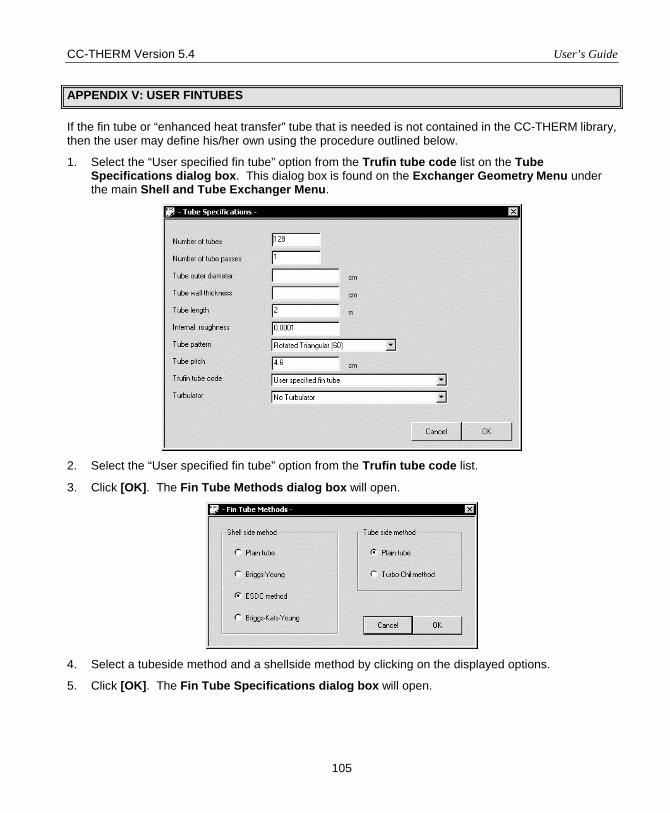
CC-THERM Version 5.4 User’s Guide
105
APPENDIX V: USER FINTUBES
If the fin tube or “enhanced heat transfer” tube that is needed is not contained in the CC-THERM library, then the user may define his/her own using the procedure outlined below.
1. Select the “User specified fin tube” option from the Trufin tube code list on the Tube Specifications dialog box. This dialog box is found on the Exchanger Geometry Menu under the main Shell and Tube Exchanger Menu.
2. Select the “User specified fin tube” option from the Trufin tube code list.
3. Click [OK]. The Fin Tube Methods dialog box will open.
4. Select a tubeside method and a shellside method by clicking on the displayed options.
5. Click [OK]. The Fin Tube Specifications dialog box will open.
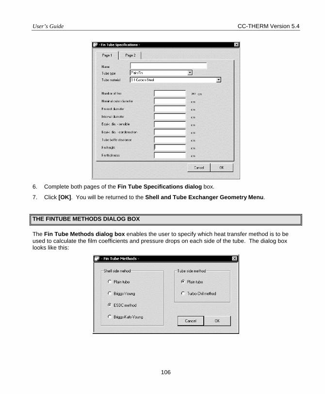
User’s Guide CC-THERM Version 5.4
106
6. Complete both pages of the Fin Tube Specifications dialog box.
7. Click [OK]. You will be returned to the Shell and Tube Exchanger Geometry Menu.
THE FINTUBE METHODS DIALOG BOX
The Fin Tube Methods dialog box enables the user to specify which heat transfer method is to be used to calculate the film coefficients and pressure drops on each side of the tube. The dialog box looks like this:
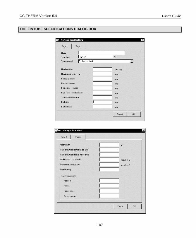
CC-THERM Version 5.4 User’s Guide
107
THE FINTUBE SPECIFICATIONS DIALOG BOX
User’s Guide CC-THERM Version 5.4
108
Page 1:
Name: Since the data for this fintube will be stored in the CHEMCAD databank, it is useful to specify a name for the tube. This name will then appear at the bottom of your fintube list whenever it is displayed.
Tube type: There are many types of enhanced heat transfer tubes. CC-THERM contains manufacturer data for many commercially available tubes for each of these types. When a user defines his/her own tube, the tube type must be identified as it determines the approval taken in the calculations. Available options are:
• Plain Fin • Koro-Dense • Turbo-Chill • Fluted • Turbulator
Tube Material: The materials commonly used for low fintubes are available. These are carbons steel, C-1/2 Moly Steel, C-1/2 Mo, and 11/4 Cr-1/2 Mo. For other materials the user can input the wall and fin THERMal conductivity. Since the main influence of materials on the calculation is the determination of tube wall resistance, this should be sufficient.
Number of Fins: Enter the number of fins per unit of length.
Nominal outer diameter: Enter a nominal diameter. This number is used only in the calculation of Turbo-Chill and Korodense in the calculation, but may be useful in making your output conform to industry standards.
Fin Root Diameter: This is the diameter of the tube from the bottom of the fins. In Figure 1 below, the fin root diameter is requested by Dfr.
Internal diameter: Low finned tubes have one internal diameter at their entrance and another internal diameter along that portion of the tabs which is finned. Referring to Figure 1, Dti represents the internal diameter of the fin tube. This is the portion of the tube which is finned.
Equivalent diameter-sensible: This is the correlating outside diameter for sensible flow in Turbo-Chill tubes. It is used only for Turbo-Chill and Korodense tubes.
Equivalent diameter-condensation: This is the correlating outside diameter for condensation in Turbo-Chill tubes. It is used only for Turbo-Chill and Korodense tuber.
Tube-to-baffle clearance: Standard TEMA clearances do not suffice for finned tube calculations. For accuracy the user should enter his/her own value.
Fin height: Enter the height of the fin from its base. Referring to Figure 1.
2D - D
fin of height h frfo==
Fin thickness: Enter the average width of the fin. This would be Lss in Figure 1 and w as shown in Figure 2.
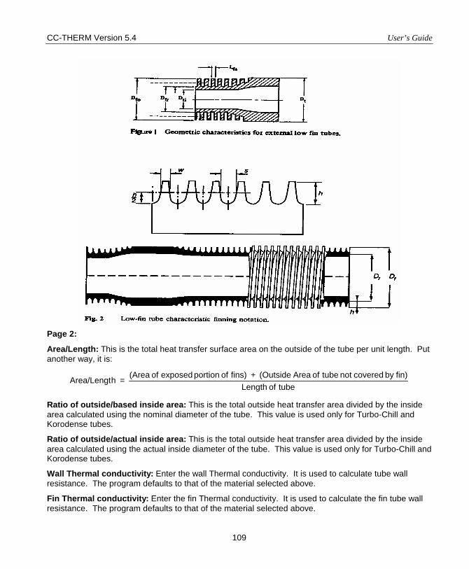
CC-THERM Version 5.4 User’s Guide
109
Page 2:
Area/Length: This is the total heat transfer surface area on the outside of the tube per unit length. Put another way, it is:
tube of Lengthfin)by covered not tube of Area(Outside fins) of portion exposed of (Area hArea/Lengt +
=
Ratio of outside/based inside area: This is the total outside heat transfer area divided by the inside area calculated using the nominal diameter of the tube. This value is used only for Turbo-Chill and Korodense tubes.
Ratio of outside/actual inside area: This is the total outside heat transfer area divided by the inside area calculated using the actual inside diameter of the tube. This value is used only for Turbo-Chill and Korodense tubes.
Wall Thermal conductivity: Enter the wall Thermal conductivity. It is used to calculate tube wall resistance. The program defaults to that of the material selected above.
Fin Thermal conductivity: Enter the fin Thermal conductivity. It is used to calculate the fin tube wall resistance. The program defaults to that of the material selected above.
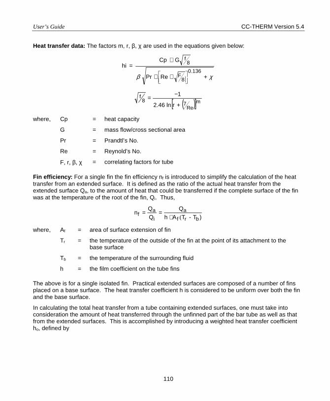
User’s Guide CC-THERM Version 5.4
110
Heat transfer data: The factors m, r, β, χ are used in the equations given below:
χβ +
∗∗
∗=
136.08
F
8f
RePr
G Cp hi
( )[ ]mRe78
f
rln46.2
1
+
−=
where, Cp = heat capacity
G = mass flow/cross sectional area
Pr = Prandtl’s No.
Re = Reynold’s No.
F, r, β, χ = correlating factors for tube
Fin efficiency: For a single fin the fin efficiency nf is introduced to simplify the calculation of the heat transfer from an extended surface. It is defined as the ratio of the actual heat transfer from the extended surface Qa, to the amount of heat that could be transferred if the complete surface of the fin was at the temperature of the root of the fin, Qi. Thus,
)T-TAhQ
QQn
brfa
ia
f (⋅==
where, Af = area of surface extension of fin
Tr = the temperature of the outside of the fin at the point of its attachment to the base surface
Tb = the temperature of the surrounding fluid
h = the film coefficient on the tube fins
The above is for a single isolated fin. Practical extended surfaces are composed of a number of fins placed on a base surface. The heat transfer coefficient h is considered to be uniform over both the fin and the base surface.
In calculating the total heat transfer from a tube containing extended surfaces, one must take into consideration the amount of heat transferred through the unfinned part of the bar tube as well as that from the extended surfaces. This is accomplished by introducing a weighted heat transfer coefficient ho, defined by

CC-THERM Version 5.4 User’s Guide
111
( )rffto AnAhAh +=
where, Ar is the surface of the tube that is not covered by fins and At is the total surface area, At = Af + Ar. The weighted fin efficiency can be defined as;
( )
−+
=
−=
tf
tf
fftf
AA
1AA
nn1AA
-1n
Enter n in this field.

User’s Guide CC-THERM Version 5.4
112
APPENDIX VI CHEMCAD THERM REFERENCES
Here is a list of references that have been used in the program for the heat transfer calculations.
EVAPORATION
E1. Chen - Correlation for Boiling Heat Transfer to Saturated Liquids in Convective Flow, Ind. Engr. Proc. Des. and Dev., Vol. 58, #3, p. 322, 1966.
E2. Baroczy - A Systematic Correlation for Two-Phase Pressure Drop, Symposium Series, Vol. 62, p. 232, 1966.
E3. Fair - What You Need to Design THERMosyphon Reboilers, Petroleum Refiner, p. 105, February 1960.
E4. Hughmark - Designing THERMosyphon Reboilers, CEP, Vol. 60 #7, p. 59. E5. Hewitt - Applications of Two-Phase Flow, CEP, p. 38, July 1982. E6. Lockhart and Martinelli - Proposed Correlation of Data for IsoTHERMal Two-Phase Two-
Component Flow in Pipes, Chem. Engr. Prog., Vol. 45 #1, p. 39, 1949. E7. Hughmark - Designing THERMosyphon Reboilers, CEP, Vol. 65 #7, p. 67, 1969. E8. Martinelli and Nelson - Prediction of Pressure Drops during Forced-Circulation Boiling of
Water, Transactions ASME, Vol. 70, p. 695, 1948. E9. Fair - Vaporizers. . ., Chemical Engineering, p. 119, August 1963. E10. Dukler - Dynamics of Vertical Falling Film Systems, CEP, Vol. 55, #10, 1959. E11. Sinek and Young - Heat Transfer in Falling Film Long-Tube Vertical Evaporators, CEP, Vol.
58 #12, 1962. E12. Fair - Vaporizer and Reboiler Design, Chemical Engineering, July 1963. E13. Malek - Predict Nucleate Boiling Transfer Rates, Hydrocarbon Processing, February 1973. E14. Palen and Small - A New Way to Design Kettle and Internal Reboilers, Hydrocarbon
Processing, Vol. 43 #11, November 1964. E15. McNelly, M. J. - J. Imperial College Chemical Engineering Society, Vol. 7 (18) (1953); also
Perry - Sixth Edition, pp. 10-23. E16. Friedel, L. - Improved Friction Pressure Drop Correlations for Horizontal and Vertical Two-
Phase Pipe Flow European Two-Phase Flow Group Meeting, Isora, Italy, Paper E2, June 1979.
E17. Premoli, A., Francesco, D., and Prina, A. - A Dimensionless Correlation for Determining the Density of Two-Phase Mixtures, Lo Termotecnica, Vol. 25, pp. 17-26, 1971.
E18. Forster, N. K., and Zuber, N. - Dynamics of Vapor Bubbles and Boiling Heat Transfer, AIChE J., Vol. 1, No. 4 p. 531, 1955.
E19. Kutaladze, S. S. - Boiling Heat Transfer, Int. J. Heat & Mass Transfer, Vol. 4, page 31, 1961. E20. Grant, Cotchin and Henry - Tests on a Small Kettle Reboiler, Paper presented at the 21st
National Heat Transfer Conf., Seattle, WA, 1983. E21. Bowring, R. W. - A Simple but Accurate Round Tube Uniform Heat Flux, Dryout Correlation
over t he Pressure Range .7 - 17 MN/m2 (100 - 2500 Psia), Rept. AEEW-R789, 1972. E22. Chung K. R. and Seban, R. A. - Heat Transfer to Evaporating Liquid Films, Journal of Heat
Transfer, Volume 93, p. 391, 1971. E23. Chun, K. R. and Seban, R. A. - Performance Prediction of Falling-Film Evaporator, Journal of
Heat Transfer, Volume 94, p. 432, 1972. E24. Junkham, G. H., Bergles, A. E., Nirmalan, V., and Ravigurajan, T. - Investigation of
Turbulators for Fire Tube Boilers, Journal of Heat Transfer, Vol. 107, p. 354, May 1985.

CC-THERM Version 5.4 User’s Guide
113
E25. Hewitt, et. al.; Pgs. 537-550. E26. VDI Heat Atlas; 1992; Pgs. Md1-Md7.
E27. Jensen, M. K. and Bensler, A. P. - Saturated Forced-Convective Boiling Heat Transfer with Twisted-Tape Inserts, Journal of Heat Transfer, Vol. 108, p. 93, February 1986.
CONDENSATION
C1. Bell and Khaly - Approximate Method for Multi-Component Condensation, American Institute of Chemical Engineers Symposium Series, Vol. 69, #131, p. 72, 1972.
C2. Silver - Gas Cooling with Aqueous Condensation, Transactions Institute of Chemical Engineers, Vol. 25, p. 30, 1974.
C3. Shekriladze - Theoretical Study of Laminar Film Condensation of Flowing Vapor, Institute of the Journal of Heat & Mass Transfer, Vol. 9, p. 581, 1966.
C4. Dukler - Dynamics of Vertical Falling Film Systems, CEP, Vol. 55 #10, 1959. C5. Kutaladze and Borisshanski - A Concise Encyclopedia of Heat Transfer, 1966. C6. Gloyer - Hydrocarbon Processing, Vol. 49 #6, p. 103, 1970. C7. Bell and Mueller - Condensation Heat Transfer, AIChE Today Series, 1971. C8. Briggs, Katz and Young - How to Design Finned-Tube Heat Exchangers, CEP, Vol. 59 #11,
November 1963. C9. Briggs and Young - Convective Heat Transfer and Pressure Drop of Air Flowing Across
Triangular Pitch Banks of Finned Tubes, CEP Symposium Series, Vol. 59 #41, 1963. C10. Boyko and Kruzhilin - Heat Transfer and Hydraulic Resistances during Condensation of
Steam in a Horizontal Tube and in a Bundle of Tubes, Vol. 10, p. 361, 1967. C11. Carpenter and Colburn - General Discussion on Heat Transfer, ASME, p. 20, 1951. C12. Webb, R. L., Ruby, T. M., Keozierski, M. A. - Prediction of the Condensation Coefficient on
Horizontal Integral-Fin Tubes, Journal of Heat Transfer, Vol. 107, p. 369, May 1985. C13. Webb, Ralph L. - A Generalized Procedure for the Design and Optimization of Fluted
Gregorig Condensing Surfaces, Journal of Heat Transfer, Vol. 101, p. 335, May 1979. C14. Rudy, T. M. and Webb, R. L. - An Analytical Model to Predict Condensate Retention on
Horizontal Integral-Fin Tubes, Journal of Heat Transfer, Vol.. 107, p. 361, May 1985. C15. Narato, P. J. - An Evaluation of Film Condensation on Horizontal Integral-Fin Tubes, Journal
of Heat Transfer, Vol. 110, p. 1287, November 1988. C16. Bribbs, D. E., Katz, D. L. and Young, E. H. - How to Design Finned-Tube Heat Exchangers,
Chemical Engineering Process, Vol. 1. C17. Transfer in Film Condensation of Pure Steam on Vertical Surfaces and Horizontal Tubes,
Teploenergetika, Vol. 4, No. 7, p. 72, 1957. C18. Hewitt, G.F.; Shires, G.L., and Bott, T.R.; Process Heat Transfer CRC Press; Boca Raton,
Florida; 1994 Pgs. 405-406. C19. Hewitt et. al.; ibid; Pgs. 402-405, 409-410, 412-413 C20. Hewitt et. al.; ibid; Pgs. 574-580, 590, 660. C21. McNaught, J.M.; Mass Transfer Correction Terius Design Methods for Multi-Component/Partial
Condensers; 18th U.S. National Heat Transfer Conference; 1979. C22. Toborek, J, palen, J.W., Breber, G.; Prediction of Horizontal Tube-side Condensation of Pure
Components using Flow Regeine Criteria; Trans. ASME, J. Heat Transfer; 1980 (102) 471-476.
C23. Hewitt, et. al.; Pgs. 580-589.
User’s Guide CC-THERM Version 5.4
114
C24. VDI Heat Atlas; 1992; Pgs. Ja6-Ja8.
SENSIBLE FLOW
S1. Sieder and Tate - Heat Transfer and Pressure Drop of Liquids in Tubes, Industrial Engineering Chemistry, Vol. 28, p. 1429, 1936.
S2. Kern - Process Heat Transfer, McGraw-Hill, 1950. S3. Bell, K. J. - Final Report, Cooperative Research Program on Shell and Tube Heat
Exchangers, University of Delaware, June 1963. S4. Tinker - Shell-Side Characteristics of Shell and Tube Heat Exchangers, Parts I, II, and III,
General Discussion of Heat Transfer, Proc. Institution of Mechanical Engineers, London, 1951 S5. Gentry, Young and Small - Rod Baffle Exchangers - THERMal-Hydraulic Predictive Methods
- Phillips Petroleum Company, Second Symposium on Shell and Tube Heat Exchangers, September 14, 1981.
S6. Chen - Flow-Induced Vibration and Noise in Tube-Bank Heat Exchangers Due to von Karman Streets, Transactions of the ASME, p. 134, 1968.
S7. Standards of the Tubular Exchanger Manufacturers Association - TEMA Section 6 - Flow Induced Vibration.
S8. Klaczak, Adam - Heat Transfer in Tubes with Spiral and Helical Turbulators, Journal of Heat Transfer, Vol. 95, p. 557, November 1973.
S9. Eubank, D. C. and Proctor W. S. - MS Thesis, Chemical Engineering Department, Massachusetts Institute of Technology, 1951.
S10. Martinelli, R. C. and Boelter, L. M. K. - University of California (Berkeley) Publ. Engr., Vol. 15, p. 23, 1942.
S11. Marner, W. J. and McMillan, H. K. - Combined Free and Forced Laminar Non-Newtonian Convection in a Vertical Tube with Constant Wall Temperature, Chemical Engineering Science, Vol. 27, p. 473, 1972.
S12. Perry, R. H. and Green, D. - Perry's Chemical Engineer's Handbook, Sixth, Edition, McGraw-Hill, 1984.
S13. VDI Heat Atlas; 1992; Pgs. Ga1-Ga8 S14. Palen, J.W., and Taborek, J.; Solution of Shellside Flow Pressure Drop and heat Transfer by
Stream Analysis Method; Heat Transfer Conference; CEP Symposium Series; AICHE; 1969. S15. Wills, J.N., and Johnston, D.; A New and Accurate Hand Calculation Method for Shellside
Pressure Drop and Flow Distribution; 22nd National Heat TransferConference, HTD, ASME; Vol. 36.
S16. Grant, I.D. R.; Flow and Pressure Drop with Single Phase and Two Phase Flow on the Shellside of Segimentally Baffled Heat Excangers; Heat Transfer Conference; CEP Symposium Series, AICHE; 1972.
S17. Hewitt, et. al.; ibid; Pg. 97 S18. Hewitt, et. al.; ibid; Pg. 98 S19. Hewitt, et. al.; ibid; Pgs. 73-79 S20. VDI Heat Atlas; 1992; Pgs. Gb1-Gb8.
CC-THERM
AIR COOLER
User’s Guide And Tutorial

CC-THERM Version 5.4 User’s Guide
115
PRODUCT OVERVIEW
INTRODUCTION TO CC-THERM AIR COOLER
CC-THERM AIR COOLER or AIR COOLER is an integrated module for the design, rating, and fouling rating of air cooled heat exchangers in the CHEMCAD Suite. It is fully integrated with CHEMCAD so process data is automatically transferred from CHEMCAD’s flowsheets to the heat exchanger sizing program, and heating curves and physical properties data are automatically generated.
EASY TO LEARN
The input for AIR COOLER is simple and concise. It is based upon the CHEMCAD input system, so any user familiar with CHEMCAD will be able to operate AIR COOLER with ease. Since the input/output systems and conventions are the same in AIR COOLER as those used in CHEMCAD, please refer to the CHEMCAD User’s Guide for these types of “How to” instructions.
TECHNICAL FEATURES
1. AIR COOLER handles the following applications:
• Sensible cooling
• Horizontal condensing
• Vertical condensing
• Reflux condensation
2. Three modes of calculation may be selected: design, rating, or fouling rating mode. In the design mode, a full optimization of the bundle dimensions, tube length, as well as tube passes per bundle will be carried out. In the fouling rating mode, fouling factors will be estimated for given process stream and air cooler. In the rating mode, the required heat transfer area will be calculated for given process stream and air cooler geometry data and compared to actual area at service.
3. Tubes may be bare or finned. Finned tube may be user defined or chosen from a library of Wolverine, HPTI, and Wieland tubes built into the program.
4. Dry wall and wet wall condensing can be accommodated.
5. Conservative and non-conservative condensing methods are available.
METHODS
User’s Guide CC-THERM Version 5.4
116
TUBESIDE HEAT TRANSFER
The tube side heat transfer is calculated differently for condensation and sensible flow.
Condensation
The program considers the following types of condensation:
Horizontal Condensation
Vertical Condensation
Reflux condenser
The program calculates tube side condensation for horizontal condenser, vertical condenser, and reflux (or knock-back) condenser for in-tube condensation. The algorithm for condensation calculation in air cooler program is similar to that in shell and tube program in that the exchanger is always broken into n (default=10) different zones. The two principal heat transfer mechanisms occurring (shear-controlled condensation and gravity-controlled condensation) are computed. In between these two extreme zones, the calculation is considered to be in the transition region between shear controlled and gravity controlled. For a condenser where the inlet quality is 100% and the outlet 0%, the flow regime usually is shear-controlled at the inlet, goes through the transition region, and finally, is gravity controlled at the outlet.
In horizontal tube condensation, two extreme cases are recognized, stratifying flow at low vapor velocity and annular flow at high vapor velocity. Stratifying flow forms when the influence of vapor shear is low and condensate film drains under gravity forming a drainage region at the top part of the tube inner and a stratified layer at the bottom. Annular flow forms when the vapor shear force is much more greater than gravity and the stratified layer disappears. For the stratifying flow, gravity controlled model obtained by Chaddock (1962) and Chato (1957) is applied to the drainage region and the heat transfer in the stratified layer is also under consideration while calculating average heat transfer coefficients. For the annular flow, shear controlled model is applied. For intermediate region between stratifying and annular flows, interpolation is applied.
In vertical tube condensation, filmwise condensation is considered. Again, the gravity controlled and shear controlled mechanism applies. The program uses the Dukler method for gravity condensation for vertical tubes. The Nusselt treatment (1916) is followed for laminar film.
The calculation of two-phase flow is an important part of an air-cooled condenser calculation, especially, of pressure drop, void fraction, and two-phase density. The calculation of the two-phase flow is computed as if all the fluid is in the liquid state. A two-phase multiplier is then used to compute the real two-phase variables. Previously, the Nelson modification (1948) of the Lockhart-Martinelli equation (1949) was used to calculate the two-phase density and pressure drop. However, more recently published correlations have proven to be far more accurate and now supplant the Lockhart-Martinelli method. For the two-phase pressure drop calculation, the program uses the Friedel correlation (1979). For void fraction, the correlation by Premoli et al. (1971) is used.
CC-THERM Version 5.4 User’s Guide
117
Multi-Component Condensation and the Effect of Non-Condensibles
All above-mentioned methods are for condensation of a pure vapor and, as such, do not take into account the presence of non-condensibles or the effect or large temperature differences between the vapor dew point and bubble point.
To account for the presence of non-condensibles or large temperature differences between inlet and outlet, a method similar to that suggested by Silver and Bell & Khaly in the above-cited references is utilized. For each step along the condensation curve, the program calculates a resistance factor to include the combined effects of a large temperature difference and the presence of non-condensibles. A very common occurrence in a steam condenser is the presence of a small quantity of air. This type gives a graphic illustration of how these resistance factors come into play. For the first several zones of such an exchanger, the condensing temperature is practically isothermal because only a small amount of air is present. In the last zone, a sizable temperature difference may exist and the amount of non-condensibles may become more significant since almost all of the vapor has condensed. Thus, the resistance factor in this last zone could be substantial, and, in such a case, half of the required area is often necessary for the last zone alone.
Sensible Flow
The Sieder-Tate equation is employed for the calculation of the tube side heat transfer coefficient in the turbulent region. The method of Martinelli and Boelter is utilized for laminar flow in a vertical tube. The method of Eubank and Proctor is used for laminar flow in horizontal tubes. Both of these correlations combine the effects of natural convection and forced convection. The flow is assumed to be laminar below a Reynolds number of 2000 and is turbulent above a Reynolds number of 10000. In the transition region, the program prorates the laminar and turbulent coefficient according to the Reynolds number to arrive at the final coefficient. The program uses the familiar Poiseuille’s law for the friction factor in the pressure drop calculation for laminar flow (Reynolds number below 2000). For turbulent flow (Reynolds number above 3000) and for the transition region between laminar and turbulent flow, the recommendations made in Section 5.23 of Perry are followed.
AIRSIDE HEAT TRANSFER
For the airside heat transfer coefficient of bare tube, the program uses ESDU methods (1973). For pressure drop, it uses the method described in the Heat Exchanger Design Handbook (1983). For finned-tube, the concept of fin efficiency is applied to allow for the radial temperature profile in calculating heat transfer coefficients. The heat transfer and pressure drop correlation suggested by ESDU (1984) is used for low fin tubes. For high fin tubes, the correlation recommended by ESDU (1986) is applied for staggered finned-tube arrays and that by Schmidt (1963) is applied for in-line arrays.
ZONE ANALYSIS
For all exchangers, the unit is analyzed using zones specified by user. AIR COOLER automatically sets up the zones and properties of each zone, but permits the user to edit or override.
User’s Guide CC-THERM Version 5.4
118
OUTPUT FEATURES
The user may select from the following output:
• A zone-by-zone print-out of the heat curve and fluid physical properties • API datasheet • A detailed print-out of overall exchanger values • A zone-by-zone print-out of heat transfer and pressure drop calculations • The stream information inlet/outlet with H, T, P, and component flow rates • Optimization data
You can request any of above output to be opened in Microsoft Word or Word Pad by using the View menu and conveniently view, edit, or print out the results. Also, the Plot menu is available at any time for the graphic display of the most important profiles, such as temperature, heat transfer coefficient, and heat flux, along the axial direction from the zone-by-zone analysis.
The editing heat curve facility also provides you with an opportunity not only to view the heat curve but also to be able to access the contents of the heat curve and make any changes to the data that you want without going through the procedures for the heat curve generation. The details of this operation will be described later.
OVERVIEW
AIR COOLER is a state-of-the-art interactive tool for rating and design of air-cooled (or heated) heat exchangers. This section gives an overall view of the program usage and the options available in the AIR COOLER main menu. More information on each option in the main menu is provided in Chapter 2.
Since AIR COOLER is integrated with the CHEMCAD Suite, the program is also equipped with sound thermodynamic models as well as a database with physical properties for over 1800 pure components.
The interactive feature of AIR COOLER allows full control of data communication. The input functions allow you to enter process data by using dialog boxes. With this input facility, you can create new problem files, review the results of problems already designed, and make modifications to previously saved problems.
There are seven general steps involved in running a heat exchanger analysis with AIR COOLER. The following list illustrates the general steps.
1. Select components and include Air in the component list.
2. Define the problem and run the flowsheet in CC-STEADY STATE. This generates CHEMCAD files.
3. Select the Sizing command on the menu bar. The Sizing Menu will open.
4. From this menu select the Heat Exchangers followed by selection of Air Cooler option.
5. The program will prompt you though the initial setup of the exchanger analysis. It will do this by displaying instructions about what you are to do next. When the instruction is cleared by clicking [OK], you will be taken to the function or dialog box appropriate for completing the instructed task. At the end of the set up process, the AIR COOLER Menu is displayed.
CC-THERM Version 5.4 User’s Guide
119
6. Inspect and edit the input as desired using the menu commands.
7. Execute the problem.
8. Review and printout.
The program performs the following tasks.
1. Performs extensive error checking.
2. Creates the airside streams for the use of air cooled heat exchangers.
3. Generates the heat curve for the tube and airsides.
4. Calculates in any of the following modes:
i. Design - The tube side inlet and outlet streams are taken from the flow sheet, the user supplies the fouling factors and airflow, and the program calculates the main dimensions of the exchangers (certain basic geometry specifications must be specified by the user).
ii. Rating – The tube side inlet and outlet streams are taken from the flow sheet and the user supplies the complete details of the exchanger geometry and dimensions, fouling factors, and airflow. The program determines whether the exchanger is too large or too small for the given application.
iii. Fouling rating – The tube side inlet and outlet streams are taken from the flow sheet and the user supplies the complete details of the exchanger geometry and dimensions and airflow. The program calculates the fouling factors required to obtain the specified performance from the exchanger.
5. Generates the output for the design/analysis of the heat exchanger.
6. Provides an interactive user interface to allow the user to change the problem specifications to rerun the problem and review the results.
7. Creates the AIR COOLER files to save all the input/output data for each exchanger.
SUMMARY
As an integrated module to the CHEMCAD Suite, AIR COOLER offers the process engineer an easy and comprehensive method of sizing or rating air-cooled heat exchangers. Since it uses the same command language as CHEMCAD, any CHEMCAD user can pick up the program in a matter of minutes. The program has been thoroughly and rigorously tested and found to be an accurate and reliable tool. It is fully supported by a staff of trained engineers. We believe it will be an indispensable tool for the library of the process engineer.
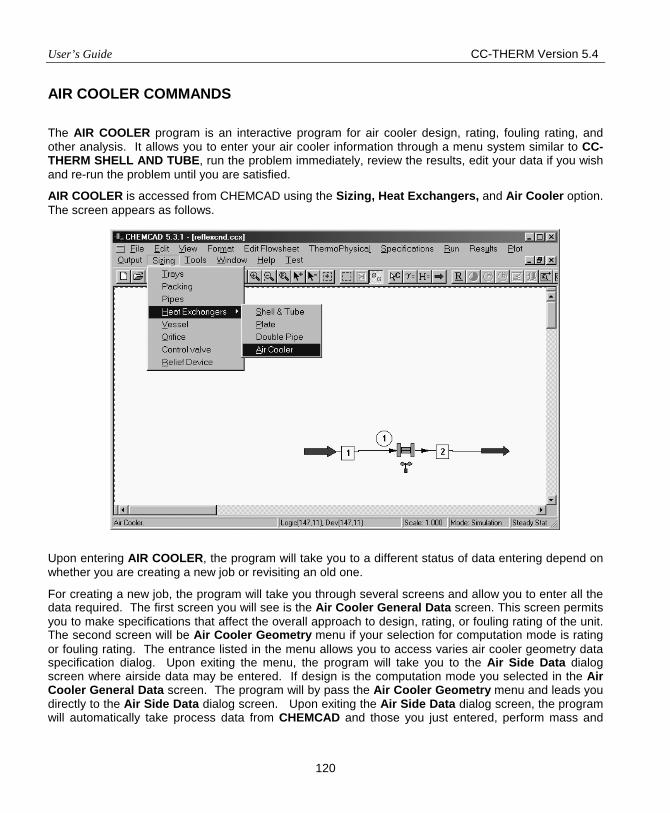
User’s Guide CC-THERM Version 5.4
120
AIR COOLER COMMANDS
The AIR COOLER program is an interactive program for air cooler design, rating, fouling rating, and other analysis. It allows you to enter your air cooler information through a menu system similar to CC-THERM SHELL AND TUBE, run the problem immediately, review the results, edit your data if you wish and re-run the problem until you are satisfied.
AIR COOLER is accessed from CHEMCAD using the Sizing, Heat Exchangers, and Air Cooler option. The screen appears as follows.
Upon entering AIR COOLER, the program will take you to a different status of data entering depend on whether you are creating a new job or revisiting an old one.
For creating a new job, the program will take you through several screens and allow you to enter all the data required. The first screen you will see is the Air Cooler General Data screen. This screen permits you to make specifications that affect the overall approach to design, rating, or fouling rating of the unit. The second screen will be Air Cooler Geometry menu if your selection for computation mode is rating or fouling rating. The entrance listed in the menu allows you to access varies air cooler geometry data specification dialog. Upon exiting the menu, the program will take you to the Air Side Data dialog screen where airside data may be entered. If design is the computation mode you selected in the Air Cooler General Data screen. The program will by pass the Air Cooler Geometry menu and leads you directly to the Air Side Data dialog screen. Upon exiting the Air Side Data dialog screen, the program will automatically take process data from CHEMCAD and those you just entered, perform mass and
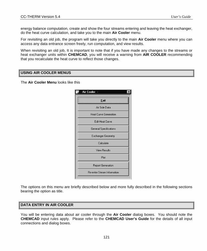
CC-THERM Version 5.4 User’s Guide
121
energy balance computation, create and show the four streams entering and leaving the heat exchanger, do the heat curve calculation, and take you to the main Air Cooler menu.
For revisiting an old job, the program will take you directly to the main Air Cooler menu where you can access any data entrance screen freely, run computation, and view results.
When revisiting an old job, It is important to note that if you have made any changes to the streams or heat exchanger units within CHEMCAD, you will receive a warning from AIR COOLER recommending that you recalculate the heat curve to reflect those changes.
USING AIR COOLER MENUS
The Air Cooler Menu looks like this
The options on this menu are briefly described below and more fully described in the following sections bearing the option as title.
DATA ENTRY IN AIR COOLER
You will be entering data about air cooler through the Air Cooler dialog boxes. You should note the CHEMCAD input rules apply. Please refer to the CHEMCAD User’s Guide for the details of all input connections and dialog boxes.
User’s Guide CC-THERM Version 5.4
122
Air Side Data – This option enables user to specify air side data and the data along with tube side data obtained from CHEMCAD are used for calculating required air flow through material and energy balance.
Heat Curve Generation – The air cooler analysis calculation takes place in two steps. First, the heat curve is generated, then the heat transfer, pressure drop calculations, and fan power estimation are performed. Heat Curve Generation performs the former calculations. This calculation determines the flows, physical properties of the heat transfer fluids in each side of the exchanger. These properties are then used in the heat transfer, pressure drop, and fan power calculation. Heat Curve Generation is therefore a necessary prerequisite to the rest of the calculations.
Edit Heat Curve – This option enables the user to edit the heat curve values calculated by Heat Curve Generation or even created heat curve through manual input. It also allows user to do linear interpolation.
General Specifications – This option allows user to define general data for an air cooler calculation including calculation mode, process type, allowed pressure drop for design mode, fouling factor, user specified heat transfer, condensation model for condensation calculation, fouling rating option, air cooler orientation, and some API reporting related items.
Exchanger Geometry – Selecting this option allows user to provide physical dimensions for tube, bundle, nozzles, miscellaneous, material specifications, and fan.
Calculate – This is used to execute the thermal analysis and pressure drop calculation.
View Results – This item is used to view the calculated results interactively.
Plot – This option enables user to graphically display heat curve, heat flux, LMTD, temperature, heat transfer coefficients, heat transfer area information on a zone-by-zone basis.
Re-enter Stream Information – This command enables user to retrieve new stream information for the tube side from CHEMCAD process flow sheet.
AIR SIDE DATA
The Air Side Data input screen allows the user to specify the air inlet and outlet temperature, static pressure, and face velocity. These inputs are used to calculate air flow. The screen is shown below.
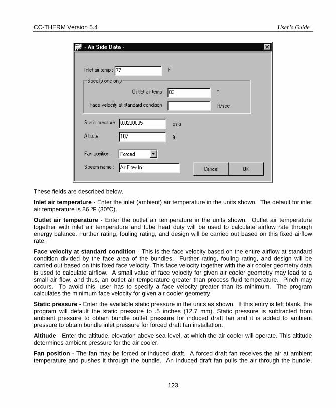
CC-THERM Version 5.4 User’s Guide
123
These fields are described below.
Inlet air temperature - Enter the inlet (ambient) air temperature in the units shown. The default for inlet air temperature is 86 ºF (30ºC).
Outlet air temperature - Enter the outlet air temperature in the units shown. Outlet air temperature together with inlet air temperature and tube heat duty will be used to calculate airflow rate through energy balance. Further rating, fouling rating, and design will be carried out based on this fixed airflow rate.
Face velocity at standard condition - This is the face velocity based on the entire airflow at standard condition divided by the face area of the bundles. Further rating, fouling rating, and design will be carried out based on this fixed face velocity. This face velocity together with the air cooler geometry data is used to calculate airflow. A small value of face velocity for given air cooler geometry may lead to a small air flow, and thus, an outlet air temperature greater than process fluid temperature. Pinch may occurs. To avoid this, user has to specify a face velocity greater than its minimum. The program calculates the minimum face velocity for given air cooler geometry.
Static pressure - Enter the available static pressure in the units as shown. If this entry is left blank, the program will default the static pressure to .5 inches (12.7 mm). Static pressure is subtracted from ambient pressure to obtain bundle outlet pressure for induced draft fan and it is added to ambient pressure to obtain bundle inlet pressure for forced draft fan installation.
Altitude - Enter the altitude, elevation above sea level, at which the air cooler will operate. This altitude determines ambient pressure for the air cooler.
Fan position - The fan may be forced or induced draft. A forced draft fan receives the air at ambient temperature and pushes it through the bundle. An induced draft fan pulls the air through the bundle,
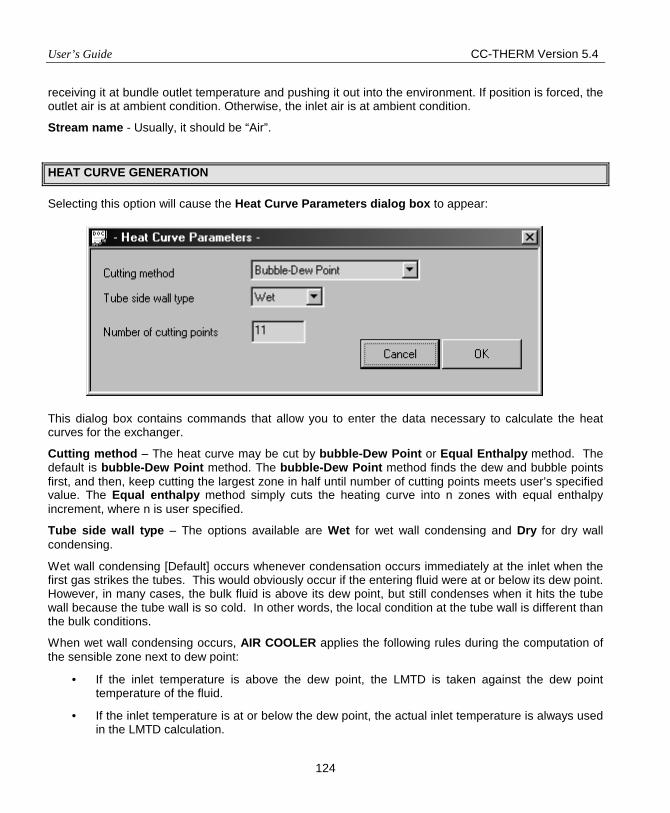
User’s Guide CC-THERM Version 5.4
124
receiving it at bundle outlet temperature and pushing it out into the environment. If position is forced, the outlet air is at ambient condition. Otherwise, the inlet air is at ambient condition.
Stream name - Usually, it should be “Air”.
HEAT CURVE GENERATION
Selecting this option will cause the Heat Curve Parameters dialog box to appear:
This dialog box contains commands that allow you to enter the data necessary to calculate the heat curves for the exchanger.
Cutting method – The heat curve may be cut by bubble-Dew Point or Equal Enthalpy method. The default is bubble-Dew Point method. The bubble-Dew Point method finds the dew and bubble points first, and then, keep cutting the largest zone in half until number of cutting points meets user’s specified value. The Equal enthalpy method simply cuts the heating curve into n zones with equal enthalpy increment, where n is user specified.
Tube side wall type – The options available are Wet for wet wall condensing and Dry for dry wall condensing.
Wet wall condensing [Default] occurs whenever condensation occurs immediately at the inlet when the first gas strikes the tubes. This would obviously occur if the entering fluid were at or below its dew point. However, in many cases, the bulk fluid is above its dew point, but still condenses when it hits the tube wall because the tube wall is so cold. In other words, the local condition at the tube wall is different than the bulk conditions.
When wet wall condensing occurs, AIR COOLER applies the following rules during the computation of the sensible zone next to dew point:
• If the inlet temperature is above the dew point, the LMTD is taken against the dew point temperature of the fluid.
• If the inlet temperature is at or below the dew point, the actual inlet temperature is always used in the LMTD calculation.
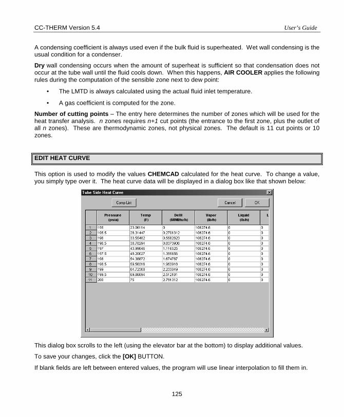
CC-THERM Version 5.4 User’s Guide
125
A condensing coefficient is always used even if the bulk fluid is superheated. Wet wall condensing is the usual condition for a condenser.
Dry wall condensing occurs when the amount of superheat is sufficient so that condensation does not occur at the tube wall until the fluid cools down. When this happens, AIR COOLER applies the following rules during the computation of the sensible zone next to dew point:
• The LMTD is always calculated using the actual fluid inlet temperature.
• A gas coefficient is computed for the zone.
Number of cutting points – The entry here determines the number of zones which will be used for the heat transfer analysis. n zones requires n+1 cut points (the entrance to the first zone, plus the outlet of all n zones). These are thermodynamic zones, not physical zones. The default is 11 cut points or 10 zones.
EDIT HEAT CURVE
This option is used to modify the values CHEMCAD calculated for the heat curve. To change a value, you simply type over it. The heat curve data will be displayed in a dialog box like that shown below:
This dialog box scrolls to the left (using the elevator bar at the bottom) to display additional values.
To save your changes, click the [OK] BUTTON.
If blank fields are left between entered values, the program will use linear interpolation to fill them in.
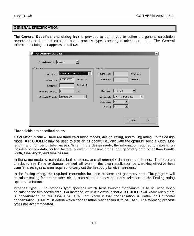
User’s Guide CC-THERM Version 5.4
126
GENERAL SPECIFICATION
The General Specifications dialog box is provided to permit you to define the general calculation parameters such as calculation mode, process type, exchanger orientation, etc. The General Information dialog box appears as follows.
These fields are described below.
Calculation mode – There are three calculation modes, design, rating, and fouling rating. In the design mode, AIR COOLER may be used to size an air cooler, i.e., calculate the optimum bundle width, tube length, and number of tube passes. When in the design mode, the information required to make a run includes stream data, fouling factors, allowable pressure drops, and geometry data other than bundle width, tube length, and tube passes.
In the rating mode, stream data, fouling factors, and all geometry data must be defined. The program checks to see if the exchanger defined will work in the given application by checking effective heat transfer area against area required to carry out the heat duty for given streams.
In the fouling rating, the required information includes streams and geometry data. The program will calculate fouling factors on tube, air, or both sides depends on user’s selection on the Fouling rating option ratio button.
Process type - The process type specifies which heat transfer mechanism is to be used when calculating the film coefficients. For instance, while it is obvious that AIR COOLER will know when there is condensation on the tube side, it will not know if that condensation is Reflux or Horizontal condensation. User must define which condensation mechanism is to be used. The following process types are accommodated.
CC-THERM Version 5.4 User’s Guide
127
Tubeside Airside Sensible flow Sensible flow Horizontal condensation Vertical condensation Reflux condensation
Allowable press. drop - Input of this variable is required for design run. 75% of the input value will allocated for tube bundle pressure drop and 25% of it will be for nozzle pressure drop. For rating and fouling rating, this field will disappear from the dialog box.
Fouling factor - Input of this variable is used for rating and design calculation. It is a thermal resistance included to account for the fouling. Its value is arbitrary and defines how often you want to clean the tubes. The default is 0.001 in English units on tube side and 0.0001 for airside.
Coefficient - Input of this variable is optional. If you want to specify shell or tube side film heat transfer coefficient, you could enter the value in the corresponding field. The program will take this value in calculating the local overall heat transfer coefficient for each zone.
Condensation Model – Condensation model could be Chemstations’ or VDI model. This option only appears when a condensation process is chosen.
Fouling rating option, Tube side – This option makes the program to rate tube side fouling factor. It requires air side fouling factor specified. It appears on the screen only if Calculation mode is set to fouling rating.
Fouling rating option, Air side – This option makes the program to rate air side fouling factor. It requires tube side fouling factor specified. It appears on the screen only if Calculation mode is set to fouling rating.
Fouling rating option, Both – This option makes the program to rate tube and air side fouling factors. Under this option, the program will assume the fouling factors on tube and air sides are equal. This option appears on the screen only if Calculation mode is set to fouling rating.
Orientation - Specify whether the tube bundle is oriented horizontally or vertically.
Design code - Select the design code to be used. These standards refer mostly to the mechanical details of the exchanger. Therefore, the thermal design and analyses are not heavily influenced by this choice. The available options are:
A - ASME Section VIII - Div. 1
B - British Standard 5500
D - DIN A.D. Merkblatter
Code stamp - Enter a [Y] here, if the air cooler must be stamped for ASME Section VIII - Div. 1. This entry is purely for output on the API data sheet. It has no impact upon the thermal calculation.
API 661 - Enter a [Y] here, if the air cooler must conform to the requirements of API 661, “Air Cooled Heat Exchangers for General Refinery Service."
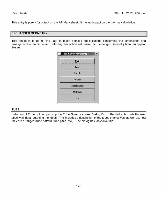
User’s Guide CC-THERM Version 5.4
128
This entry is purely for output on the API data sheet. It has no impact on the thermal calculation.
EXCHANGER GEOMETRY
This option is to permit the user to make detailed specifications concerning the dimensions and arrangement of an air cooler. Selecting this option will cause the Exchanger Geometry Menu to appear like so:
TUBE Selection of Tube option opens up the Tube Specifications Dialog Box. The dialog box lets the user specify all data regarding the tubes. This includes a description of the tubes themselves, as well as, how they are arranged (tube pattern, tube pitch, etc.). The dialog box looks like this.
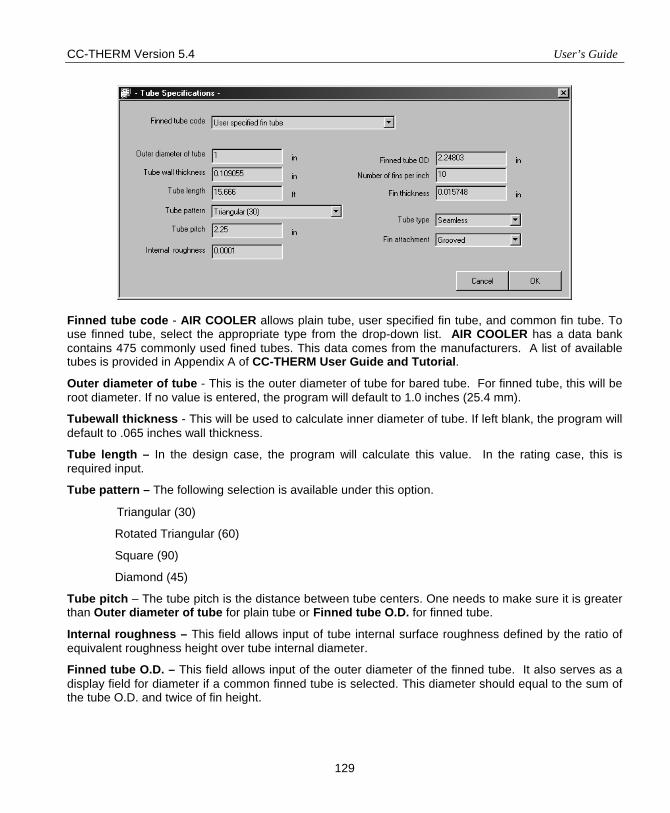
CC-THERM Version 5.4 User’s Guide
129
Finned tube code - AIR COOLER allows plain tube, user specified fin tube, and common fin tube. To use finned tube, select the appropriate type from the drop-down list. AIR COOLER has a data bank contains 475 commonly used fined tubes. This data comes from the manufacturers. A list of available tubes is provided in Appendix A of CC-THERM User Guide and Tutorial.
Outer diameter of tube - This is the outer diameter of tube for bared tube. For finned tube, this will be root diameter. If no value is entered, the program will default to 1.0 inches (25.4 mm).
Tubewall thickness - This will be used to calculate inner diameter of tube. If left blank, the program will default to .065 inches wall thickness.
Tube length – In the design case, the program will calculate this value. In the rating case, this is required input.
Tube pattern – The following selection is available under this option.
Triangular (30)
Rotated Triangular (60)
Square (90)
Diamond (45)
Tube pitch – The tube pitch is the distance between tube centers. One needs to make sure it is greater than Outer diameter of tube for plain tube or Finned tube O.D. for finned tube.
Internal roughness – This field allows input of tube internal surface roughness defined by the ratio of equivalent roughness height over tube internal diameter.
Finned tube O.D. – This field allows input of the outer diameter of the finned tube. It also serves as a display field for diameter if a common finned tube is selected. This diameter should equal to the sum of the tube O.D. and twice of fin height.
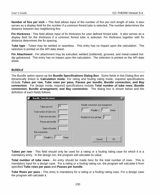
User’s Guide CC-THERM Version 5.4
130
Number of fins per inch – This field allows input of the number of fins per inch length of tube. It also serves as a display field for the number if a common finned tube is selected. The number determines the distance between two neighboring fins.
Fin thickness - This field allows input of fin thickness for user defined finned tube. It also serves as a display field for the thickness if a common finned tube is selected. Fin thickness together with fin distance determines the fin spacing.
Tube type - Tubes may be welded or seamless. This entry has no impact upon the calculation. The selection is printed on the API data sheet.
Fin Attachment - Fin attachment may be extruded, welded (soldered), grooved, and metal-coated hot-dip galvanized. This entry has no impact upon the calculation. The selection is printed on the API data sheet.
BUNDLE
The Bundle option opens up the Bundle Specifications Dialog Box. Some fields in this Dialog Box are dynamically linked to Calculation mode. For rating and fouling rating mode, required specifications include Tubes per row, Tube rows per pass, Passes per bundle, Bundle connection, and Bay connection. For design mode, required specifications include Total number of tube rows, Bundle connection, Bundle arrangement, and Bay connection. The dialog box is shown below and the definition of each fields follows. Tubes per row - This field should only be used for a rating or a fouling rating case for which it is a mandatory entry. In the design run, the program will calculate its value.
Total number of tube rows - An entry should be made here for the total number of rows. This is mandatory input for a design case. For a rating or a fouling rating run, the program will calculate it from specified Tube rows per pass and Passes per bundle.
Tube Rows per pass - This entry is mandatory for a rating or a fouling rating case. For a design case the program will calculate it.
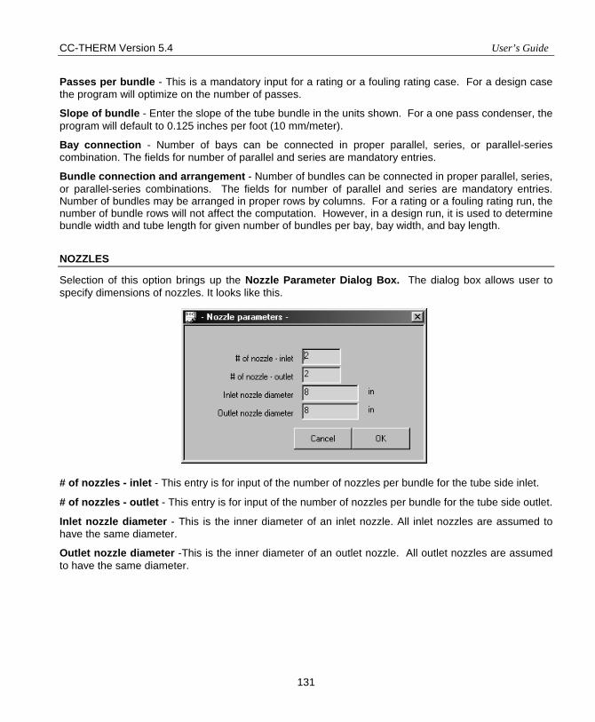
CC-THERM Version 5.4 User’s Guide
131
Passes per bundle - This is a mandatory input for a rating or a fouling rating case. For a design case the program will optimize on the number of passes.
Slope of bundle - Enter the slope of the tube bundle in the units shown. For a one pass condenser, the program will default to 0.125 inches per foot (10 mm/meter).
Bay connection - Number of bays can be connected in proper parallel, series, or parallel-series combination. The fields for number of parallel and series are mandatory entries.
Bundle connection and arrangement - Number of bundles can be connected in proper parallel, series, or parallel-series combinations. The fields for number of parallel and series are mandatory entries. Number of bundles may be arranged in proper rows by columns. For a rating or a fouling rating run, the number of bundle rows will not affect the computation. However, in a design run, it is used to determine bundle width and tube length for given number of bundles per bay, bay width, and bay length.
NOZZLES
Selection of this option brings up the Nozzle Parameter Dialog Box. The dialog box allows user to specify dimensions of nozzles. It looks like this.
# of nozzles - inlet - This entry is for input of the number of nozzles per bundle for the tube side inlet.
# of nozzles - outlet - This entry is for input of the number of nozzles per bundle for the tube side outlet.
Inlet nozzle diameter - This is the inner diameter of an inlet nozzle. All inlet nozzles are assumed to have the same diameter.
Outlet nozzle diameter -This is the inner diameter of an outlet nozzle. All outlet nozzles are assumed to have the same diameter.
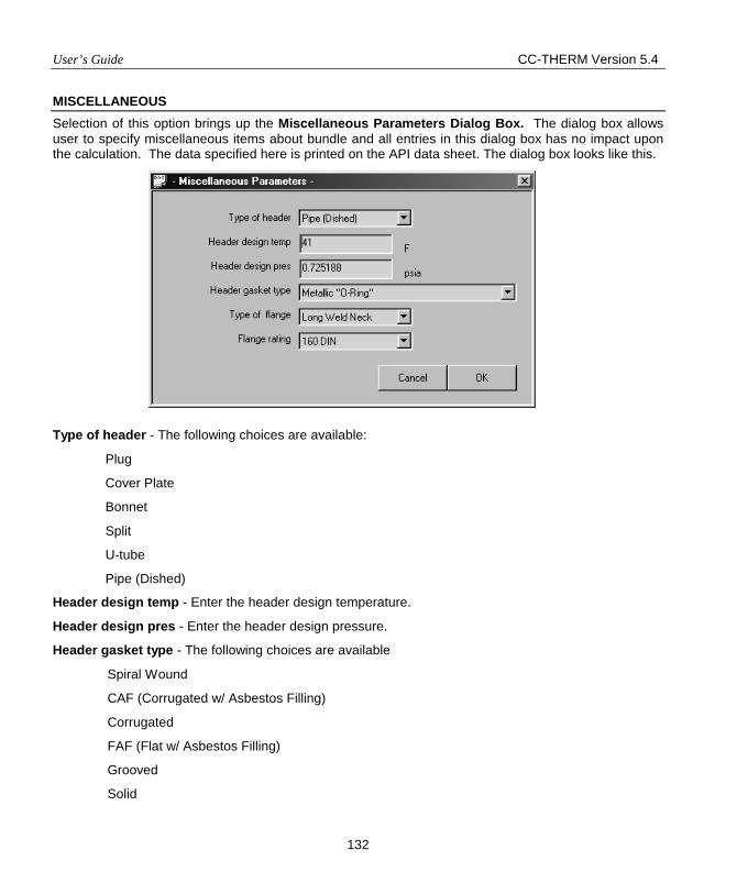
User’s Guide CC-THERM Version 5.4
132
MISCELLANEOUS Selection of this option brings up the Miscellaneous Parameters Dialog Box. The dialog box allows user to specify miscellaneous items about bundle and all entries in this dialog box has no impact upon the calculation. The data specified here is printed on the API data sheet. The dialog box looks like this.
Type of header - The following choices are available:
Plug
Cover Plate
Bonnet
Split
U-tube
Pipe (Dished)
Header design temp - Enter the header design temperature.
Header design pres - Enter the header design pressure.
Header gasket type - The following choices are available
Spiral Wound
CAF (Corrugated w/ Asbestos Filling)
Corrugated
FAF (Flat w/ Asbestos Filling)
Grooved
Solid
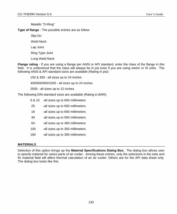
CC-THERM Version 5.4 User’s Guide
133
Metallic "O-Ring"
Type of flange - The possible entries are as follow:
Slip-On
Weld Neck
Lap Joint
Ring Type Joint
Long Weld Neck
Flange rating - If you are using a flange per ANSI or API standard, enter the class of the flange in this field. It is understood that the class will always be in psi even if you are using metric or SI units. The following ANSI & API standard sizes are available (Rating in psi):
150 & 300 - all sizes up to 24 inches
400/600/900/1500 - all sizes up to 24 inches
2500 - all sizes up to 12 inches
The following DIN standard sizes are available (Rating in BAR):
6 & 10 -all sizes up to 600 millimeters
25 -all sizes up to 600 millimeters
16 -all sizes up to 600 millimeters
40 -all sizes up to 500 millimeters
64 -all sizes up to 400 millimeters
100 -all sizes up to 350 millimeters
160 -all sizes up to 300 millimeters
MATERIALS
Selection of this option brings up the Material Specifications Dialog Box. The dialog box allows user to specify material for varies parts of air cooler. Among these entries, only the selections in the tube and fin material field will affect thermal calculation of an air cooler. Others are for the API data sheet only. The dialog box looks like this.
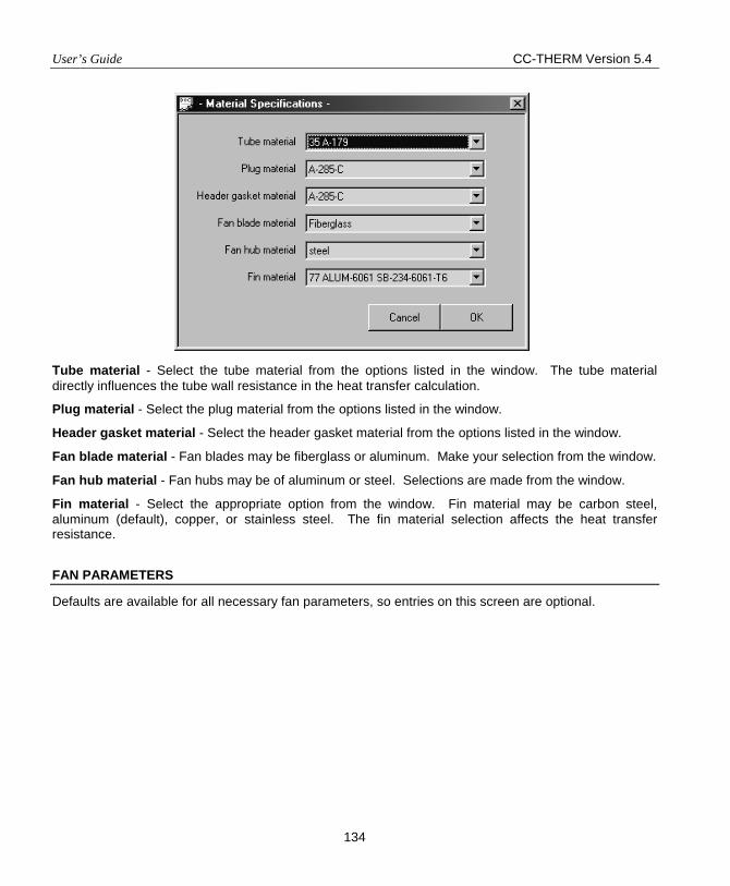
User’s Guide CC-THERM Version 5.4
134
Tube material - Select the tube material from the options listed in the window. The tube material directly influences the tube wall resistance in the heat transfer calculation.
Plug material - Select the plug material from the options listed in the window.
Header gasket material - Select the header gasket material from the options listed in the window.
Fan blade material - Fan blades may be fiberglass or aluminum. Make your selection from the window.
Fan hub material - Fan hubs may be of aluminum or steel. Selections are made from the window.
Fin material - Select the appropriate option from the window. Fin material may be carbon steel, aluminum (default), copper, or stainless steel. The fin material selection affects the heat transfer resistance.
FAN PARAMETERS
Defaults are available for all necessary fan parameters, so entries on this screen are optional.
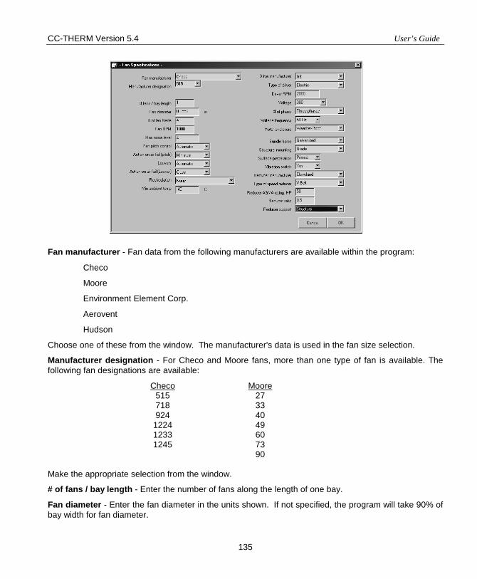
CC-THERM Version 5.4 User’s Guide
135
Fan manufacturer - Fan data from the following manufacturers are available within the program:
Checo
Moore
Environment Element Corp.
Aerovent
Hudson
Choose one of these from the window. The manufacturer's data is used in the fan size selection.
Manufacturer designation - For Checo and Moore fans, more than one type of fan is available. The following fan designations are available:
Checo Moore 515 27 718 33 924 40
1224 49 1233 60 1245 73
90 Make the appropriate selection from the window.
# of fans / bay length - Enter the number of fans along the length of one bay.
Fan diameter - Enter the fan diameter in the units shown. If not specified, the program will take 90% of bay width for fan diameter.
User’s Guide CC-THERM Version 5.4
136
# of fan blades - Enter the number of fan blades.
Fan RPM - Enter the fan speed in revolutions per minute.
Maximum noise level - Enter the maximum permissible noise level of the fan.
Fan pitch control - The user may choose from none, manual, or automatic. Selections are made from the window and output to the API datasheet.
Action on air failure - The fan pitch on air failure may be:
None (no specification)
Minimum
Maximum
Lockup
Select the appropriate option from the window. This selection will be output to the API datasheet.
Louvers - Louvers may open and close manually or automatically. Therefore the user may choose from the following options:
None (no specification)
Manual
Automatic
Selections may be made from the appropriate window. This selection is output to the API datasheet.
Action on air failure (Louvers) - On air failure the louvers may fail open, closed, or locked. Therefore, the options available to the user are:
None (no specification)
Open
Closed
Locked up
Selections are made from the window. This selection is output to the API datasheet.
Recirculation - The possible choices are:
None (no specification)
Internal
External around bundle sides
External around bundle ends
Selections are made from the window. This selection is output to the API datasheet.
Minimum ambient temperature - Enter the minimum ambient temperature in the units displayed. This value helps determine the operating range of the fan and is output to the API datasheet.
CC-THERM Version 5.4 User’s Guide
137
Drive manufacturer - The user may chose from GE, RELIANCE, or WESTINGHOUSE drivers. Make the appropriate selection from the window. This selection will be output to the API datasheet.
Type of driver - The driver type may be unspecified, electric, or steam turbine.
Driver RPM - The following choices are typical for an electric motor:
3500 / 1750 / 1450 / 1150 / 870 / 580
For a steam turbine, the RPM may be different than those shown above for an electric motor.
Voltage - The following choices are available for electric voltage:
220 v
380 v
440 v
460 v
# of phases - The following choices are available for number of phases:
Three phases
One phase
Voltage frequency - The following choices are available for voltage frequency:
60 Hz
50 Hz
Motor enclosure - The following choices are available for the motor enclosure:
Unspecified
Drip-Proof
Weather-Proof - class I
Weather-Proof - class II
TEFC - Totally Enclosed Fan Cooled
Explosion Proof
Bundle frame - The following choices are available:
Galvanized
Welded
Structural mounting - The following choices are available:
Grade Mounted
Piperack
Surface preparation - The following choices are available:
User’s Guide CC-THERM Version 5.4
138
No surface preparation
Primed
Vibration switch - Enter a ‘Y’ if a vibration switch will be used.
Reducer manufacturer - The following choices are available for speed reducer manufacturer field:
Leave Choice Blank
Philadelphia
Cleveland
Falk
Type of speed reducer - The following choices are available:
Leave Choice Blank
Right Angle Gear
V-Belt
Direct Coupled
Reducer AGMA rating - Enter the AGMA rating of the Speed reducer in HP or kW.
Reducer ratio - Enter the speed reducer ratio.
Reducer support - The following choices are available for speed reducer support:
Structure
Pedestal
CALCULATE
The RUN command tells the program to execute the design, rate, or fouling rating calculation. To begin the run, move the pointer to the Calculate option and click the left mouse button. After the command is issued, the program performs a complete data check to make sure there is no missing or unreasonable information. If errors or warnings are detected, the program shows an error message on the screen. The program allows you to either change the data or ignore the error messages.
The progress of calculation will be reported in the status line in the lower left corner for design, heating curve, and fouling rating calculation. A message of completion pops-up after calculation is done.
VIEW RESULTS
The View Results option enables the user to interactively review selected results on the screen. When selected, the VIEW MENU appears on the screen like so:
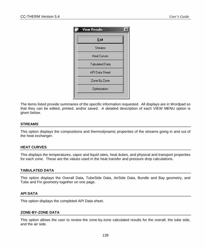
CC-THERM Version 5.4 User’s Guide
139
The items listed provide summaries of the specific information requested. All displays are in Wordpad so that they can be edited, printed, and/or saved. A detailed description of each VIEW MENU option is given below.
STREAMS
This option displays the compositions and thermodynamic properties of the streams going in and out of the heat exchanger.
HEAT CURVES
This displays the temperatures, vapor and liquid rates, heat duties, and physical and transport properties for each zone. These are the values used in the heat transfer and pressure drop calculations.
TABULATED DATA
This option displays the Overall Data, TubeSide Data, AirSide Data, Bundle and Bay geometry, and Tube and Fin geometry together on one page.
API DATA
This option displays the completed API Data sheet.
ZONE-BY-ZONE DATA
This option allows the user to review the zone-by-zone calculated results for the overall, the tube side, and the air side.
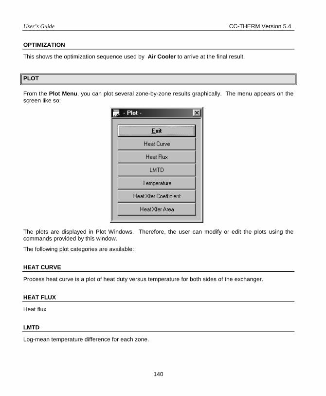
User’s Guide CC-THERM Version 5.4
140
OPTIMIZATION
This shows the optimization sequence used by Air Cooler to arrive at the final result.
PLOT
From the Plot Menu, you can plot several zone-by-zone results graphically. The menu appears on the screen like so:
The plots are displayed in Plot Windows. Therefore, the user can modify or edit the plots using the commands provided by this window.
The following plot categories are available:
HEAT CURVE
Process heat curve is a plot of heat duty versus temperature for both sides of the exchanger.
HEAT FLUX
Heat flux
LMTD
Log-mean temperature difference for each zone.
CC-THERM Version 5.4 User’s Guide
141
TEMPERATURE
Tube side, tube side wall, shell side wall and shell side temperatures for each zone.
HEAT XFER COEFFICIENT
Overall, tube side, shell side, tube fouling and shell fouling heat transfer coefficients for each zone.
HEAT XFER AREA
Heat transfer area calculated for each zone.
RE-ENTER STREAM INFORMATION
This command allows user to retrieve new streams from CHEMCAD flow sheet. This is very useful in case any stream entering or exiting the exchanger is changed.
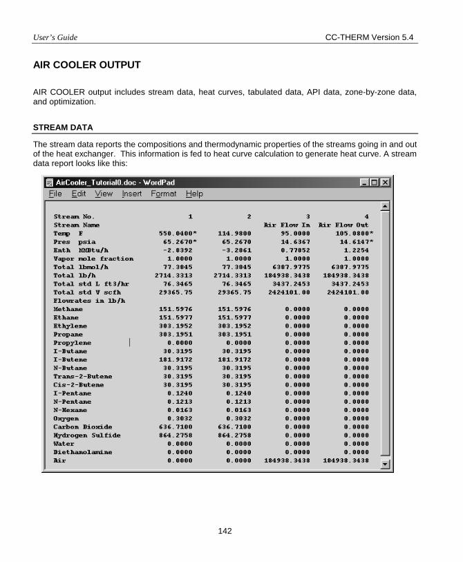
User’s Guide CC-THERM Version 5.4
142
AIR COOLER OUTPUT
AIR COOLER output includes stream data, heat curves, tabulated data, API data, zone-by-zone data, and optimization.
STREAM DATA
The stream data reports the compositions and thermodynamic properties of the streams going in and out of the heat exchanger. This information is fed to heat curve calculation to generate heat curve. A stream data report looks like this:
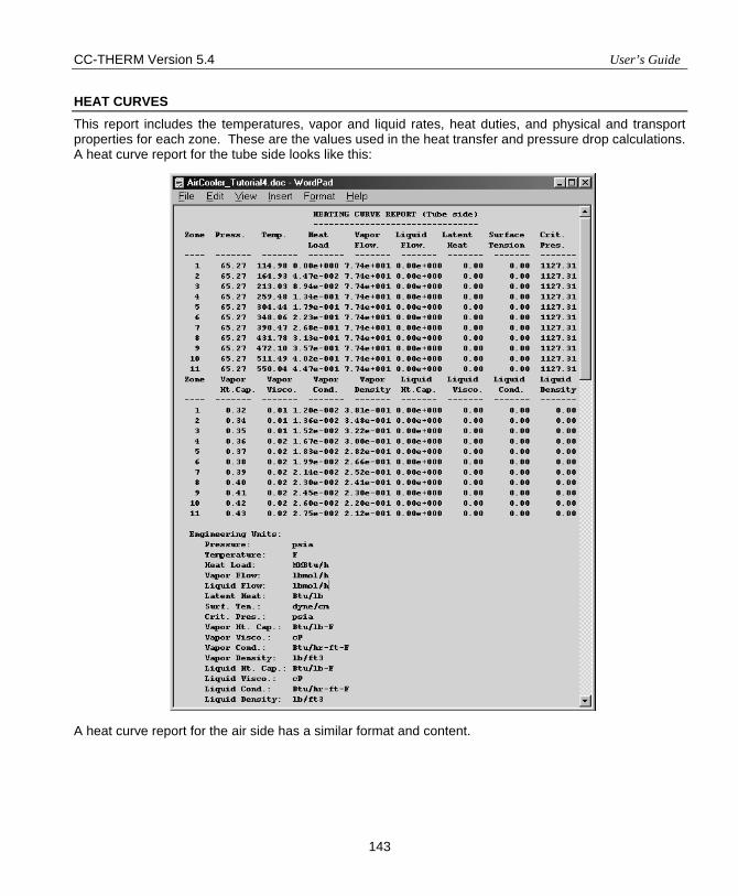
CC-THERM Version 5.4 User’s Guide
143
HEAT CURVES This report includes the temperatures, vapor and liquid rates, heat duties, and physical and transport properties for each zone. These are the values used in the heat transfer and pressure drop calculations. A heat curve report for the tube side looks like this: A heat curve report for the air side has a similar format and content.
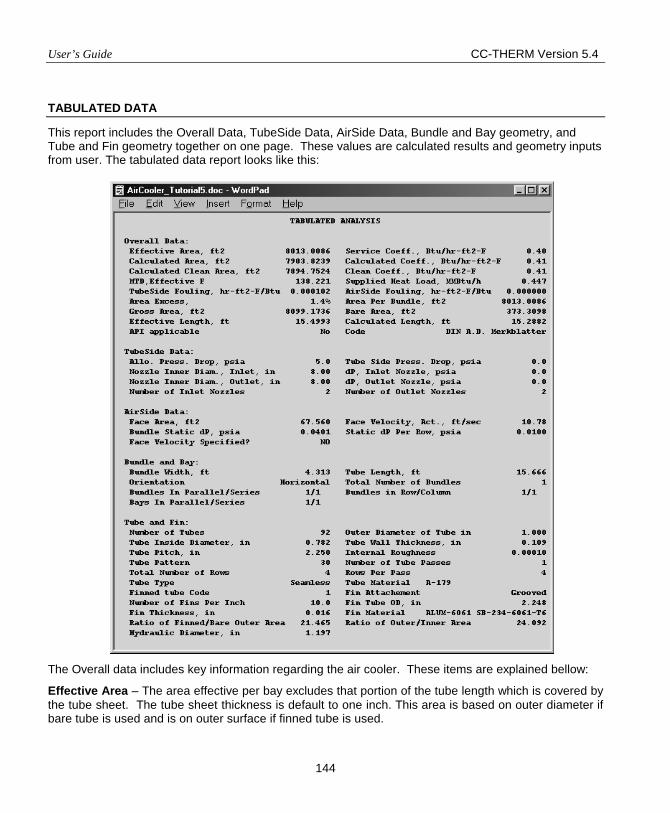
User’s Guide CC-THERM Version 5.4
144
TABULATED DATA
This report includes the Overall Data, TubeSide Data, AirSide Data, Bundle and Bay geometry, and Tube and Fin geometry together on one page. These values are calculated results and geometry inputs from user. The tabulated data report looks like this: The Overall data includes key information regarding the air cooler. These items are explained bellow:
Effective Area – The area effective per bay excludes that portion of the tube length which is covered by the tube sheet. The tube sheet thickness is default to one inch. This area is based on outer diameter if bare tube is used and is on outer surface if finned tube is used.
CC-THERM Version 5.4 User’s Guide
145
Service Coefficient – This is the overall heat transfer coefficient for the whole exchanger based on the Effective Area of exchanger at service. It is defined as:
) EffectiveMTD,() AreaEffective( Load) (Heat Coeff.) (Service =
Calculated Area – The calculated heat transfer area required to carry out the heat load. In CC-THERM AIR COOLER, heat transfer calculation is carried out zone by zone. The Calculated Area is the sum of the incremental areas for all zones.
Calculated Coefficient – This is the overall heat transfer coefficient for the whole exchanger. It is defined as:
) EffectiveMTD,() AreaCalculated( Load) (Heat Coeff.) d(Calculate =
Calculated Clean Area – The calculated heat transfer area required to carry out the heat load when the heat transfer surface is clean. The Calculated Clean Area is the sum of the incremental clean areas for all zones.
Clean Coefficient – This is the overall heat transfer coefficient for the whole exchanger based on the Calculated Clean Area. It is defined as:
) EffectiveMTD,() AreaClean Calculated( Load) (Heat Coeff.) (Clean =
MTD, Effective –The overall effective or corrected log mean temperature difference which is defined as:
∑=
iCMTDiQ
Load) (HeatEffective)(MTD,
Where, Qi = the incremental heat duty of zone I,
CMTDi = the corrected log mean temperature difference for zone i.
Heat Load – The enthalpy difference between the inlet and outlet process streams of the air cooler.
TubeSide Fouling – The tube side fouling factor. For design and rating run, tube side fouling factor is user specified. For fouling rating run, the program will calculate the fouling factor for given streams and air cooler geometry.
AirSide Fouling – The air side fouling factor. For design and rating run, tube side fouling factor is user specified. For fouling rating run, the program will calculate the fouling factor for given streams and air cooler geometry.
Area Excess – The excess area for the present calculation. It is defined as:
%)100() AreaEffective(
Area)d(Calculate - ) Area(Effective Excess) (Area =
This value is always expressed as a percent. A negative value indicates that the exchanger is undersurfaced in rating. When making a design run, the program will find a heat exchanger so that the
User’s Guide CC-THERM Version 5.4
146
excess is the minimum positive value. When making a fouling rating run, the program finds the fouling factors so that the Area Excess is zero.
Area Per Bundle – The effective area per bundle excludes that portion of the tube length which is covered by the tube sheet.
Gross Area – The gross area per bay based on outer surface.
Bare Area – The area based on outer tube diameter or root diameter. It is the effective area per bay.
Effective Length – The length effective excludes that portion of the tube length which is covered by the tube sheet.
Calculated Length – The calculated tube length required to carry out the heat load. In CC-THERM AIR COOLER, heat transfer calculation is carried out zone by zone. The calculated length is the sum of the incremental length for all zones.
API applicable – Input of the API 661 option in the General Specifications Dialog Box is printed here.
Code – Input of the Design code option in the General Specifications Dialog Box is printed here.
Allowed Pressure Drop – The maximum allowed pressure drop for the process side. This value is used as one of the design constrain.
Tube Side Pressure Drop. – The tube side pressure drop of all bundles.
Inner Nozzle Diameter, Inlet – Input of the Inlet nozzle diameter field in the Nozzle Parameter Dialog Box is printed here.
dP, Inlet Nozzle – The pressure drop through inlet nozzles.
Inner Nozzle Diameter Outlet – Input of the Outlet nozzle diameter field in the Nozzle Parameter Dialog Box is printed here.
dP, Outlet Nozzle – The pressure drop through outlet nozzles.
Number of Inlet Nozzles – Input of the # of nozzles - Inlet field in the Nozzle Parameter Dialog Box is printed here.
Number of Outlet Nozzles – Input of the # of nozzles - Outlet field in the Nozzle Parameter Dialog Box is printed here.
Face Area – The face area per pay. It equals to tube length times bundle width times number of bundles.
Face Velocity – The face velocity is obtained by air volumetric flow rate at service condition divided by Face Area.
Calculated Static dP – The calculated static pressure drop of air flow through the tube bundle. To improve calculation result, the difference between Calculated Static dP and the Static pressure specified in the Air Side Data screen should be minimized.
Static dP Per Row – The calculated static pressure drop of air flow through a tube row.
Face Velocity Specified? – Yes, if face velocity is specified as input, otherwise, No.
CC-THERM Version 5.4 User’s Guide
147
Bundle width – The bundle width is calculated through the number of tubes per row, tube pitch, and tube pattern for rating and fouling rating run. In the design run, it is calculated from the optimum bay width and user specified total number of bundles per bay and number of bundle rows.
Tube length – see Tube Specifications Dialog Box.
Orientation – The orientation of tube bundle may be horizontal or vertical as specified by user.
Total Number of Bundles – The total number of bundles of entire units.
Bundles in Parallel/Series – see Bundle connection and arrangement in the Bundle specification screen.
Bundles in Row/Column – see Bundle connection and arrangement in the Bundle specification screen.
Bays in Parallel/Series – see Bay connection in the Bundle specification screen.
Number of Tubes – This is the total number of tubes per bundle which is calculated from the Total number of tube rows and Tubes per row.
Outer Diameter of Tube – see Tube Specifications Dialog Box.
Tube Inside Diameter – The inside diameter is estimated from the Outer Diameter of Tube and Tubewall thickness.
Tube Wall Thickness – Input to the Tubewall thickness field In the Tube Specifications Dialog Box is printed here.
Tube Pitch – see Tube Specifications Dialog Box.
Internal roughness – see Tube Specifications Dialog Box.
Tube Pattern – see Tube Specifications Dialog Box.
Number of Tube Passes – Input in the Passes per bundle field in the Bundle specification screen is printed here.
Total Number of Rows – see Total number of tube rows in the Bundle specification screen.
Rows Per Pass – see Tube Rows per pass in the Bundle specification screen.
Tube Type – see Tube Specifications Dialog Box.
Tube Material – See Material Specifications Dialog Box.
Finned Tube Code – See Tube Specifications Dialog Box.
Fin Attachment – See Tube Specifications Dialog Box.
Number of Fins Per Inch – see Tube Specifications Dialog Box.
Fin Tube OD – see Tube Specifications Dialog Box.
Fin Thickness – see Tube Specifications Dialog Box.
Fin Material – See Material Specifications Dialog Box.

User’s Guide CC-THERM Version 5.4
148
Ratio of Finned/Bare Outer Area – The ratio of finned tube outer surface area over bare tube outer surface area. The finned tube outer surface area is the sum of the total surface area of the fins and the total surface area of the tube wall between the fins. The bare tube outer surface area is the surface area based on the tube outer diameter.
Ratio of Outer/Inner Area – The ratio of tube outer surface area over tube inner surface area. The tube outer surface area is the finned tube outer surface area for finned tube and the bare tube outer surface area for bare tube. The tube inner surface area is the surface area based on the tube inner diameter.
Hydraulic Diameter – The equivalent hydraulic diameter or equivalent projected diameter (Dreq). This is essentially a correlation value establishing an equivalent cross-flow area as compared to a bare tube.
)Lft)(Nf)(Llth(2DfrDreq +=
where Dfr = the root diameter
Llth= = the fin height
Nf = the number of fins per unit length
Lft = Fin thickness
API DATA
This report includes the completed API Data sheet. The first page of the data sheet includes general data, performance data for process side, performance data for airside, and design-material-construction data. It looks like:
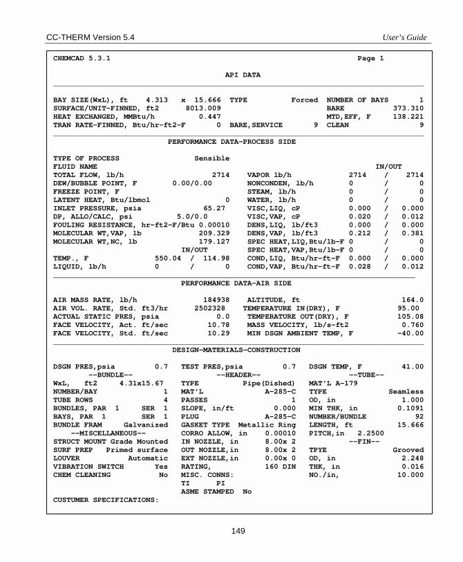
CC-THERM Version 5.4 User’s Guide
149
CHEMCAD 5.3.1 Page 1 API DATA ____________________________________________________________________________________ BAY SIZE(WxL), ft 4.313 x 15.666 TYPE Forced NUMBER OF BAYS 1 SURFACE/UNIT-FINNED, ft2 8013.009 BARE 373.310 HEAT EXCHANGED, MMBtu/h 0.447 MTD,EFF, F 138.221 TRAN RATE-FINNED, Btu/hr-ft2-F 0 BARE,SERVICE 9 CLEAN 9 ____________________________________________________________________________________ PERFORMANCE DATA-PROCESS SIDE TYPE OF PROCESS Sensible FLUID NAME IN/OUT TOTAL FLOW, lb/h 2714 VAPOR lb/h 2714 / 2714 DEW/BUBBLE POINT, F 0.00/0.00 NONCONDEN, lb/h 0 / 0 FREEZE POINT, F STEAM, lb/h 0 / 0 LATENT HEAT, Btu/lbmol 0 WATER, lb/h 0 / 0 INLET PRESSURE, psia 65.27 VISC,LIQ, cP 0.000 / 0.000 DP, ALLO/CALC, psi 5.0/0.0 VISC,VAP, cP 0.020 / 0.012 FOULING RESISTANCE, hr-ft2-F/Btu 0.00010 DENS,LIQ, lb/ft3 0.000 / 0.000 MOLECULAR WT,VAP, lb 209.329 DENS,VAP, lb/ft3 0.212 / 0.381 MOLECULAR WT,NC, lb 179.127 SPEC HEAT,LIQ,Btu/lb-F 0 / 0 IN/OUT SPEC HEAT,VAP,Btu/lb-F 0 / 0 TEMP., F 550.04 / 114.98 COND,LIQ, Btu/hr-ft-F 0.000 / 0.000 LIQUID, lb/h 0 / 0 COND,VAP, Btu/hr-ft-F 0.028 / 0.012 __________________________________________________________________________________ PERFORMANCE DATA-AIR SIDE AIR MASS RATE, lb/h 184938 ALTITUDE, ft 164.0 AIR VOL. RATE, Std. ft3/hr 2502328 TEMPERATURE IN(DRY), F 95.00 ACTUAL STATIC PRES, psia 0.0 TEMPERATURE OUT(DRY), F 105.08 FACE VELOCITY, Act. ft/sec 10.78 MASS VELOCITY, lb/s-ft2 0.760 FACE VELOCITY, Std. ft/sec 10.29 MIN DSGN AMBIENT TEMP, F -40.00 ____________________________________________________________________________________ DESIGN-MATERIALS-CONSTRUCTION DSGN PRES,psia 0.7 TEST PRES,psia 0.7 DSGN TEMP, F 41.00 --BUNDLE-- --HEADER-- --TUBE-- WxL, ft2 4.31x15.67 TYPE Pipe(Dished) MAT'L A-179 NUMBER/BAY 1 MAT'L A-285-C TYPE Seamless TUBE ROWS 4 PASSES 1 OD, in 1.000 BUNDLES, PAR 1 SER 1 SLOPE, in/ft 0.000 MIN THK, in 0.1091 BAYS, PAR 1 SER 1 PLUG A-285-C NUMBER/BUNDLE 92 BUNDLE FRAM Galvanized GASKET TYPE Metallic Ring LENGTH, ft 15.666 --MISCELLANEOUS-- CORRO ALLOW, in 0.00010 PITCH,in 2.2500 STRUCT MOUNT Grade Mounted IN NOZZLE, in 8.00x 2 --FIN-- SURF PREP Primed surface OUT NOZZLE,in 8.00x 2 TPYE Grooved LOUVER Automatic EXT NOZZLE,in 0.00x 0 OD, in 2.248 VIBRATION SWITCH Yes RATING, 160 DIN THK, in 0.016 CHEM CLEANING No MISC. CONNS: NO./in, 10.000 TI PI ASME STAMPED No CUSTUMER SPECIFICATIONS:
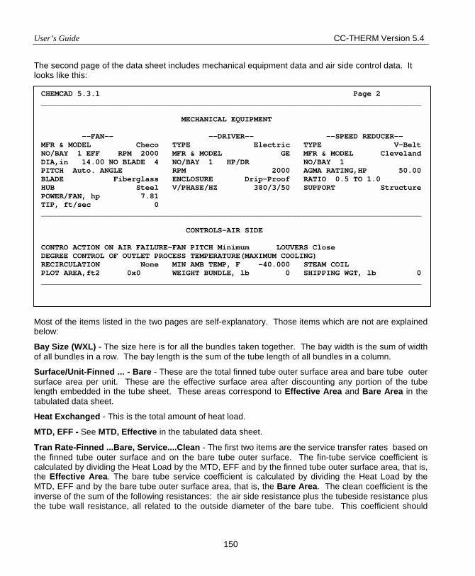
User’s Guide CC-THERM Version 5.4
150
The second page of the data sheet includes mechanical equipment data and air side control data. It looks like this:
Most of the items listed in the two pages are self-explanatory. Those items which are not are explained below:
Bay Size (WXL) - The size here is for all the bundles taken together. The bay width is the sum of width of all bundles in a row. The bay length is the sum of the tube length of all bundles in a column.
Surface/Unit-Finned ... - Bare - These are the total finned tube outer surface area and bare tube outer surface area per unit. These are the effective surface area after discounting any portion of the tube length embedded in the tube sheet. These areas correspond to Effective Area and Bare Area in the tabulated data sheet.
Heat Exchanged - This is the total amount of heat load.
MTD, EFF - See MTD, Effective in the tabulated data sheet.
Tran Rate-Finned ...Bare, Service....Clean - The first two items are the service transfer rates based on the finned tube outer surface and on the bare tube outer surface. The fin-tube service coefficient is calculated by dividing the Heat Load by the MTD, EFF and by the finned tube outer surface area, that is, the Effective Area. The bare tube service coefficient is calculated by dividing the Heat Load by the MTD, EFF and by the bare tube outer surface area, that is, the Bare Area. The clean coefficient is the inverse of the sum of the following resistances: the air side resistance plus the tubeside resistance plus the tube wall resistance, all related to the outside diameter of the bare tube. This coefficient should
CHEMCAD 5.3.1 Page 2 ____________________________________________________________________________________ MECHANICAL EQUIPMENT --FAN-- --DRIVER-- --SPEED REDUCER-- MFR & MODEL Checo TYPE Electric TYPE V-Belt NO/BAY 1 EFF RPM 2000 MFR & MODEL GE MFR & MODEL Cleveland DIA,in 14.00 NO BLADE 4 NO/BAY 1 HP/DR NO/BAY 1 PITCH Auto. ANGLE RPM 2000 AGMA RATING,HP 50.00 BLADE Fiberglass ENCLOSURE Drip-Proof RATIO 0.5 TO 1.0 HUB Steel V/PHASE/HZ 380/3/50 SUPPORT Structure POWER/FAN, hp 7.81 TIP, ft/sec 0 ____________________________________________________________________________________ CONTROLS-AIR SIDE CONTRO ACTION ON AIR FAILURE-FAN PITCH Minimum LOUVERS Close DEGREE CONTROL OF OUTLET PROCESS TEMPERATURE(MAXIMUM COOLING) RECIRCULATION None MIN AMB TEMP, F -40.000 STEAM COIL PLOT AREA,ft2 0x0 WEIGHT BUNDLE, lb 0 SHIPPING WGT, lb 0 ____________________________________________________________________________________
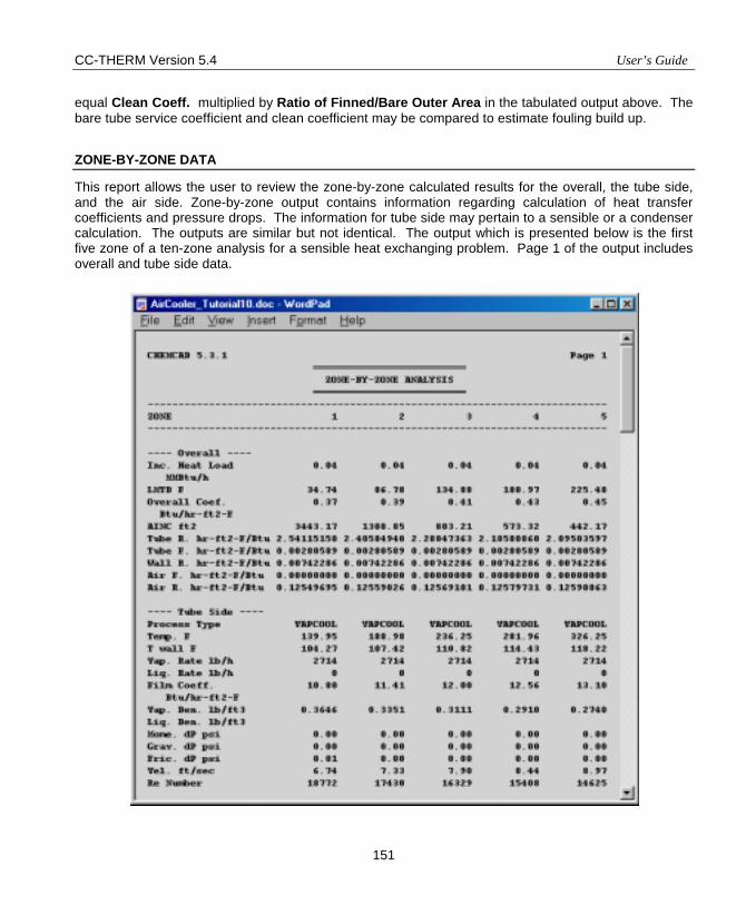
CC-THERM Version 5.4 User’s Guide
151
equal Clean Coeff. multiplied by Ratio of Finned/Bare Outer Area in the tabulated output above. The bare tube service coefficient and clean coefficient may be compared to estimate fouling build up.
ZONE-BY-ZONE DATA
This report allows the user to review the zone-by-zone calculated results for the overall, the tube side, and the air side. Zone-by-zone output contains information regarding calculation of heat transfer coefficients and pressure drops. The information for tube side may pertain to a sensible or a condenser calculation. The outputs are similar but not identical. The output which is presented below is the first five zone of a ten-zone analysis for a sensible heat exchanging problem. Page 1 of the output includes overall and tube side data.
User’s Guide CC-THERM Version 5.4
152
Items in this page are explained below:
Inc. Heat Load - The incremental heat load at each zone. The incremental heat load will be identical for each zone if equal enthalpy method is used to cut the heating curve. They might differ with each other if bubble-dew point method is used.
LMTD – The corrected local log mean temperature difference based on the four temperature points of each zone.
Overall Coef. – The local overall heat transfer coefficient based on AINC, the tube outer surface area of the corresponding zone.
AINC –The tube outer surface area of each zone.
Tube R. – The tube side heat transfer resistance due to fluid.
Tube F. – The tube side heat transfer resistance due to fouling.
Wall T. – The tube side heat transfer resistance due to metal wall.
Air F. – The air side heat transfer resistance due to fouling.
Air R. – The air side heat transfer resistance due to air.
Temp. – The average temperature of the two cutting points on the heating curve for the zone.
T Wall – The zone average metal wall surface temperature on the air or tube side.
Vap. Rate – The local vapor mass flow rate.
Liq. Rate – The local liquid mass flow rate.
Film Coeff. – The local heat transfer coefficient of fluid film.
Vap. Den. – The local vapor density.
Liq. Den. – The local liquid density.
Mome. dP – The tube side pressure drop due to momentum change.
Grav. dP – The tube side pressure drop due to gravitation.
Fric. dP – The pressure drop due to friction loss.
Vel. – The tube side fluid velocity.
Re Number – The Reynolds number of flow.
Page 2 of the output includes the air side data. It is shown below:
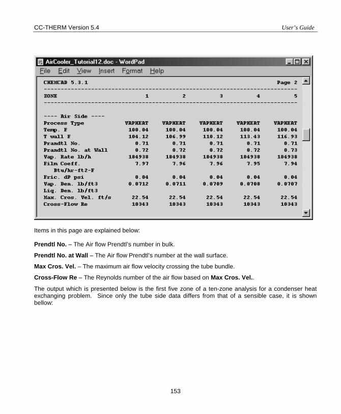
CC-THERM Version 5.4 User’s Guide
153
Items in this page are explained below: Prendtl No. – The Air flow Prendtl’s number in bulk.
Prendtl No. at Wall – The Air flow Prendtl’s number at the wall surface.
Max Cros. Vel. – The maximum air flow velocity crossing the tube bundle.
Cross-Flow Re – The Reynolds number of the air flow based on Max Cros. Vel..
The output which is presented below is the first five zone of a ten-zone analysis for a condenser heat exchanging problem. Since only the tube side data differs from that of a sensible case, it is shown bellow:
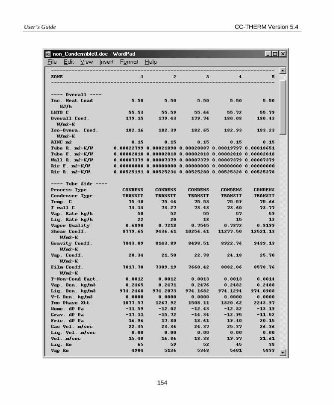
User’s Guide CC-THERM Version 5.4
154
CC-THERM Version 5.4 User’s Guide
155
Items in this page are explained below: Iso-Overa. Coef. - The local overall heat transfer coefficient when gas film resistance is not account of.
Condenser Type – This is the flow type at each zone of the exchanger. There are three basic types of flow which may exist in a condenser.
SHEARCT - The vapor velocity is so high that the shear force on the surface of condensate film is dominant comparing to gravity force and this type of heat transfer is generally referred as shear-controlled.
GRAVCTL - The vapor velocity is low and the shear force on the surface of a condensate film is negligible. This type of heat transfer is generally known as gravity-controlled film.
TRANSIT - The SHEARCT and GRAVCTL are basically the two extremes of the flows which may occur during condensation. In going from the SHEARCT controlled to the GRAVCTL controlled, there is a transition region which is usually called the TRANSIT (for transition) region. There are times when the vapor velocity is so low that the predominant regime is the TRANSIT or even GRAVCTL for very low vapor velocities.
Vapor Quality – The vapor quality at each zone of the exchanger. The number 1.0 indicates that the flow is all vapor and 0.0 indicates no vapor.
Shear Coeff. – The shear-controlled heat transfer coefficient. This coefficient is calculated at each zone whether or not it is the controlling coefficient.
Gravity Coeff. – The gravity-controlled heat transfer coefficient. This coefficient is calculated at each zone whether or not it is the controlling coefficient.
Vap. Coeff. – Tthe heat transfer coefficient of the vapor phase. This coefficient is very important in the calculation of the overall heat transfer coefficient, especially so when there are large amounts of non-condensable present. This coefficient is also calculated at each zone of the exchanger.
Film Coeff. – The heat transfer coefficient through condensate film. This coefficient is calculated at each zone of the exchanger.
T-Non-Cond Fact – The tube side non-condensable factor. It is a factor which is calculated to reflect the overall effects of non-condensable or a wide-boiling mixture. When calculating the tube side heat transfer resistance at each zone, the gas film resistance is multiplied by T-Non-Cond Fact. When the effects of non-condensable are small, the T-Non-Cond Fact. (resistance factor) will be small and the overall coefficient, Overall Coef. will approach to Iso-Overa. Coef. - the pure condensation overall coefficient. On the other hand, when there are large amounts of non-condensable present or there is a wide boiling mixture, the T-Non-Cond Fact term may become quite large and, consequently, the "true" overall heat transfer coefficient will also diminish.
V-L Den – The two phase mixing density.
Two Phase Xtt – This is a two-phase multiplier which is calculated at each zone. When there are large amounts of vapor present, the multiplier will be quite large. This multiplier is applied to zone pressure drop, and summed over all the zones to arrive at the overall pressure drop.
User’s Guide CC-THERM Version 5.4
156
Vap. Vel. – The vapor flow velocity.
Liq Vel. – The liquid flow velocity
Vel. – The two phase flow velocity
Liq Re – The liquid flow Renolds number.
Vap Re – The vapor flow Renolds number.
OPTIMIZATION
This shows the optimization sequence used by Air Cooler to arrive at the final result. The optimization printout only occurs if you are in the design mode. The program deliberately begins with an obviously undersized unit in order to insure that the procedure does not miss the optimum result. The program uses basically two criteria to arrive at the optimum result.
• Supplied area is greater than the required area
• Pressure drop allowables are met on the tubeside
In order to find the smallest unit, which will satisfy these criteria, the program will vary the following parameters:
• Tube passes
• bay length
• bay width
To make best use of fan (one or two) covered area in each bay, the program will also follow the arrangement as shown in the table bellow to arrive at best combination of bay length and width.
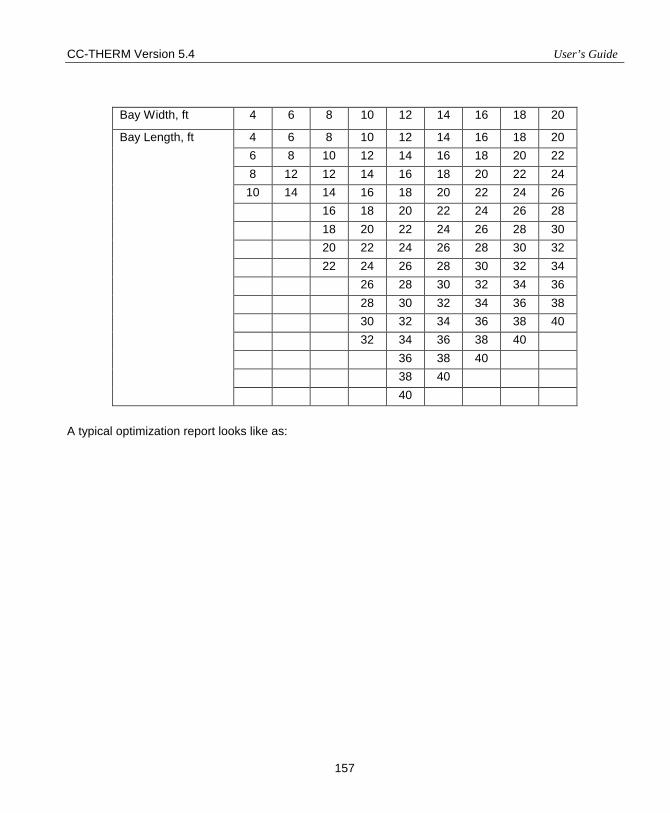
CC-THERM Version 5.4 User’s Guide
157
Bay Width, ft 4 6 8 10 12 14 16 18 20
4 6 8 10 12 14 16 18 20 6 8 10 12 14 16 18 20 22 8 12 12 14 16 18 20 22 24
10 14 14 16 18 20 22 24 26 16 18 20 22 24 26 28 18 20 22 24 26 28 30 20 22 24 26 28 30 32 22 24 26 28 30 32 34 26 28 30 32 34 36 28 30 32 34 36 38 30 32 34 36 38 40 32 34 36 38 40 36 38 40 38 40
Bay Length, ft
40 A typical optimization report looks like as:
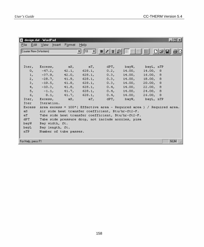
User’s Guide CC-THERM Version 5.4
158
CC-THERM
PLATE HEAT EXCHANGER
User’s Guide And Tutorial

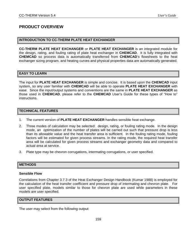
CC-THERM Version 5.4 User’s Guide
159
PRODUCT OVERVIEW
INTRODUCTION TO CC-THERM PLATE HEAT EXCHANGER
CC-THERM PLATE HEAT EXCHANGER or PLATE HEAT EXCHANGER is an integrated module for the design, rating, and fouling rating of plate heat exchanger in CHEMCAD. It is fully integrated with CHEMCAD so process data is automatically transferred from CHEMCAD’s flowsheets to the heat exchanger sizing program, and heating curves and physical properties data are automatically generated.
EASY TO LEARN
The input for PLATE HEAT EXCHANGER is simple and concise. It is based upon the CHEMCAD input system, so any user familiar with CHEMCAD will be able to operate PLATE HEAT EXCHANGER with ease. Since the input/output systems and conventions are the same in PLATE HEAT EXCHANGER as those used in CHEMCAD, please refer to the CHEMCAD User’s Guide for these types of “How to” instructions.
TECHNICAL FEATURES
1. The current version of PLATE HEAT EXCHANGER handles sensible heat exchange.
2. Three modes of calculation may be selected: design, rating, or fouling rating mode. In the design mode, an optimization of the number of plates will be carried out such that pressure drop is less than its allowable value and the heat transfer area is sufficient. In the fouling rating mode, fouling factors will be estimated for given process streams. In the rating mode, the required heat transfer area will be calculated for given process streams and exchanger geometry data and compared to actual area at service.
3. Plate type may be chevron corrugations, intermating corrugations, or user specified.
METHODS
Sensible Flow
Correlations from Chapter 3.7.3 of the Heat Exchanger Design Handbook (Kumar 1988) is employed for the calculation of the heat transfer coefficient and pressure drop of intermating and chevron plate. For user specified plate, models similar to those for chevron plate are used while parameters in these models are user specified.
OUTPUT FEATURES
The user may select from the following output:
User’s Guide CC-THERM Version 5.4
160
• A print-out of the heat curve and fluid physical properties • A detailed print-out of overall exchanger values • The stream information inlet/outlet with H, T, P, and component flow rates
Any of the above output can be opened in Microsoft Word or WordPad by using the View menu. Therefore results can be viewed, edited, or printed. The editing heat curve facility also provides an opportunity not only to view the heat curve but also to be able to access the contents of the heat curve and make any changes to the data without going through the procedures for the heat curve generation. The details of this operation will be described later.
OVERVIEW
PLATE HEAT EXCHANGER is a state-of-the-art interactive tool for the rating and design of plate heat exchangers. This section gives an overall view of the program usage and the options available in the PLATE HEAT EXCHANGER main menu. More information on each option in the main menu is provided in Chapter 2.
Since PLATE HEAT EXCHANGER is integrated with CHEMCAD, the program is also equipped with sound thermodynamic models as well as a database with physical properties for over 1800 pure components.
The interactive feature of PLATE HEAT EXCHANGER allows full control of data communication. The input functions allows the entering of process data by using dialog boxes. With this input facility, the user can create new problem files, review the results of problems already designed, and make modifications to previously saved problems.
There are seven general steps involved in running a heat exchanger analysis with PLATE HEAT EXCHANGER. The following list illustrates the general steps.
1. Define the problem and run the flowsheet in CHEMCAD. This generates CHEMCAD files.
2. Select the Sizing command on the menu bar. The Sizing Menu will open.
3. From this menu select the Heat Exchangers followed by selection of Plate option.
4. The program will prompt the user through the initial setup of the exchanger analysis. It will do this by displaying instructions about what to do next. When the instruction is cleared by clicking [OK], you will be taken to the function or dialog box appropriate for completing the instructed task. At the end of the set up process, the PLATE HEAT EXCHANGER Menu is displayed.
5. Inspect and edit the input as desired using the menu commands.
6. Execute the problem.
7. Review and printout.
The program performs the following tasks.
1. Performs extensive error checking.
2. Generates the heat curve for the cold and hot side.
CC-THERM Version 5.4 User’s Guide
161
3. Calculates in any of the following modes:
i. Design - The inlet and outlet stream datum of the cold and hot side are taken from the flow sheet, the user supplies the fouling factors and allowable pressure drop, and the program calculates the number of plates required (other basic geometry specifications must be specified by the user).
ii. Rating – The inlet and outlet stream datum of the cold and hot side are taken from the flow sheet and the user supplies the complete details of the exchanger geometry and dimensions, and fouling factors. The program determines whether the exchanger is too large or too small for the given application.
iii. Fouling rating – The inlet and outlet stream datum of the cold and hot side are taken from the flow sheet and the user supplies the complete details of the exchanger geometry and dimensions. The program calculates the fouling factors required to obtain the specified performance from the exchanger.
4. Generates the output for the design/analysis of the heat exchanger.
5. Provides an interactive user interface to allow the user to change the problem specifications to rerun the problem and review the results.
6. Creates the PLATE HEAT EXCHANGER files to save all the input/output data for each exchanger.
SUMMARY
As an integrated module to CHEMCAD, PLATE HEAT EXCHANGER offers the process engineer an easy and comprehensive method of sizing or rating plate heat exchangers. Since it uses the same command language as CHEMCAD, any CHEMCAD user can pick up the program in a matter of minutes. The program has been thoroughly and rigorously tested and found to be an accurate and reliable tool. It is fully supported by a staff of trained engineers. We believe it will be an indispensable tool for the library of the process engineer.
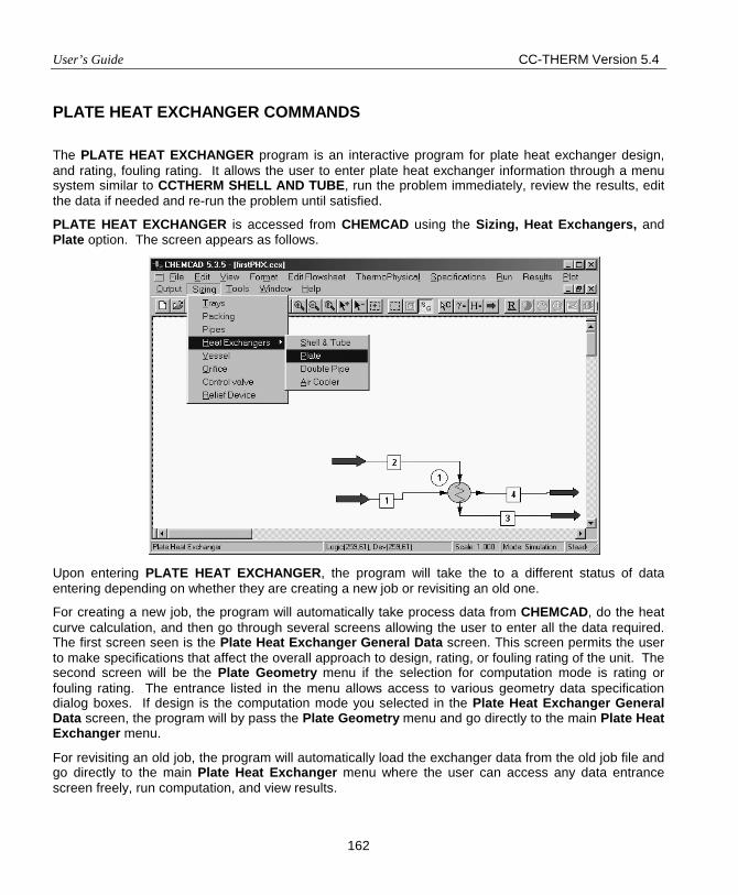
User’s Guide CC-THERM Version 5.4
162
PLATE HEAT EXCHANGER COMMANDS
The PLATE HEAT EXCHANGER program is an interactive program for plate heat exchanger design, and rating, fouling rating. It allows the user to enter plate heat exchanger information through a menu system similar to CCTHERM SHELL AND TUBE, run the problem immediately, review the results, edit the data if needed and re-run the problem until satisfied.
PLATE HEAT EXCHANGER is accessed from CHEMCAD using the Sizing, Heat Exchangers, and Plate option. The screen appears as follows. Upon entering PLATE HEAT EXCHANGER, the program will take the to a different status of data entering depending on whether they are creating a new job or revisiting an old one.
For creating a new job, the program will automatically take process data from CHEMCAD, do the heat curve calculation, and then go through several screens allowing the user to enter all the data required. The first screen seen is the Plate Heat Exchanger General Data screen. This screen permits the user to make specifications that affect the overall approach to design, rating, or fouling rating of the unit. The second screen will be the Plate Geometry menu if the selection for computation mode is rating or fouling rating. The entrance listed in the menu allows access to various geometry data specification dialog boxes. If design is the computation mode you selected in the Plate Heat Exchanger General Data screen, the program will by pass the Plate Geometry menu and go directly to the main Plate Heat Exchanger menu.
For revisiting an old job, the program will automatically load the exchanger data from the old job file and go directly to the main Plate Heat Exchanger menu where the user can access any data entrance screen freely, run computation, and view results.
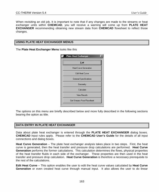
CC-THERM Version 5.4 User’s Guide
163
When revisiting an old job, It is important to note that if any changes are made to the streams or heat exchanger units within CHEMCAD, you will receive a warning will come up from PLATE HEAT EXCHANGER recommending obtaining new stream data from CHEMCAD flowsheet to reflect those changes.
USING PLATE HEAT EXCHANGER MENUS
The Plate Heat Exchanger Menu looks like this The options on this menu are briefly described below and more fully described in the following sections bearing the option as title.
DATA ENTRY IN PLATE HEAT EXCHANGER
Data about plate heat exchanger is entered through the PLATE HEAT EXCHANGER dialog boxes. CHEMCAD input rules apply. Please refer to the CHEMCAD User’s Guide for the details of all input connections and dialog boxes.
Heat Curve Generation – The plate heat exchanger analysis takes place in two steps. First, the heat curve is generated, then the heat transfer and pressure drop calculations are performed. Heat Curve Generation performs the former calculations. This calculation determines the flows, physical properties of the heat transfer fluids in each side of the exchanger. These properties are then used in the heat transfer and pressure drop calculation. Heat Curve Generation is therefore a necessary prerequisite to the rest of the calculations.
Edit Heat Curve – This option enables the user to edit the heat curve values calculated by Heat Curve Generation or even created heat curve through manual input. It also allows the user to do linear
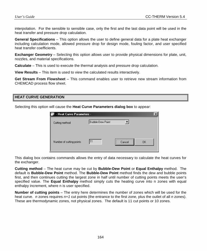
User’s Guide CC-THERM Version 5.4
164
interpolation. For the sensible to sensible case, only the first and the last data point will be used in the heat transfer and pressure drop calculation.
General Specifications – This option allows the user to define general data for a plate heat exchanger including calculation mode, allowed pressure drop for design mode, fouling factor, and user specified heat transfer coefficients.
Exchanger Geometry – Selecting this option allows user to provide physical dimensions for plate, unit, nozzles, and material specifications.
Calculate – This is used to execute the thermal analysis and pressure drop calculation.
View Results – This item is used to view the calculated results interactively.
Get Stream From Flowsheet – This command enables user to retrieve new stream information from CHEMCAD process flow sheet.
HEAT CURVE GENERATION
Selecting this option will cause the Heat Curve Parameters dialog box to appear: This dialog box contains commands allows the entry of data necessary to calculate the heat curves for the exchanger.
Cutting method – The heat curve may be cut by Bubble-Dew Point or Equal Enthalpy method. The default is Bubble-Dew Point method. The Bubble-Dew Point method finds the dew and bubble points first, and then continues cutting the largest zone in half until number of cutting points meets the user’s specified value. The Equal Enthalpy method simply cuts the heating curve into n zones with equal enthalpy increment, where n is user specified.
Number of cutting points – The entry here determines the number of zones which will be used for the heat curve. n zones requires n+1 cut points (the entrance to the first zone, plus the outlet of all n zones). These are thermodynamic zones, not physical zones. The default is 11 cut points or 10 zones.
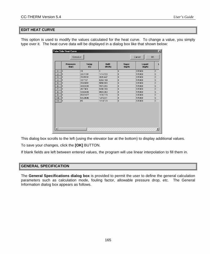
CC-THERM Version 5.4 User’s Guide
165
EDIT HEAT CURVE
This option is used to modify the values calculated for the heat curve. To change a value, you simply type over it. The heat curve data will be displayed in a dialog box like that shown below: This dialog box scrolls to the left (using the elevator bar at the bottom) to display additional values.
To save your changes, click the [OK] BUTTON.
If blank fields are left between entered values, the program will use linear interpolation to fill them in.
GENERAL SPECIFICATION
The General Specifications dialog box is provided to permit the user to define the general calculation parameters such as calculation mode, fouling factor, allowable pressure drop, etc. The General Information dialog box appears as follows.
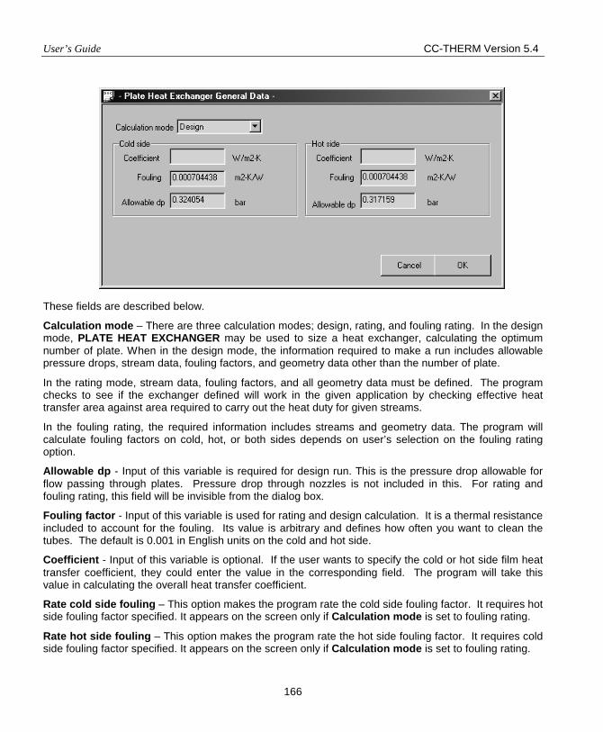
User’s Guide CC-THERM Version 5.4
166
These fields are described below.
Calculation mode – There are three calculation modes; design, rating, and fouling rating. In the design mode, PLATE HEAT EXCHANGER may be used to size a heat exchanger, calculating the optimum number of plate. When in the design mode, the information required to make a run includes allowable pressure drops, stream data, fouling factors, and geometry data other than the number of plate.
In the rating mode, stream data, fouling factors, and all geometry data must be defined. The program checks to see if the exchanger defined will work in the given application by checking effective heat transfer area against area required to carry out the heat duty for given streams.
In the fouling rating, the required information includes streams and geometry data. The program will calculate fouling factors on cold, hot, or both sides depends on user’s selection on the fouling rating option.
Allowable dp - Input of this variable is required for design run. This is the pressure drop allowable for flow passing through plates. Pressure drop through nozzles is not included in this. For rating and fouling rating, this field will be invisible from the dialog box.
Fouling factor - Input of this variable is used for rating and design calculation. It is a thermal resistance included to account for the fouling. Its value is arbitrary and defines how often you want to clean the tubes. The default is 0.001 in English units on the cold and hot side.
Coefficient - Input of this variable is optional. If the user wants to specify the cold or hot side film heat transfer coefficient, they could enter the value in the corresponding field. The program will take this value in calculating the overall heat transfer coefficient.
Rate cold side fouling – This option makes the program rate the cold side fouling factor. It requires hot side fouling factor specified. It appears on the screen only if Calculation mode is set to fouling rating.
Rate hot side fouling – This option makes the program rate the hot side fouling factor. It requires cold side fouling factor specified. It appears on the screen only if Calculation mode is set to fouling rating.
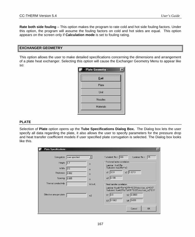
CC-THERM Version 5.4 User’s Guide
167
Rate both side fouling – This option makes the program to rate cold and hot side fouling factors. Under this option, the program will assume the fouling factors on cold and hot sides are equal. This option appears on the screen only if Calculation mode is set to fouling rating.
EXCHANGER GEOMETRY
This option allows the user to make detailed specifications concerning the dimensions and arrangement of a plate heat exchanger. Selecting this option will cause the Exchanger Geometry Menu to appear like so:
PLATE
Selection of Plate option opens up the Tube Specifications Dialog Box. The Dialog box lets the user specify all data regarding the plate, it also allows the user to specify parameters for the pressure drop and heat transfer coefficient models if user specified plate corrugation is selected. The Dialog box looks like this.
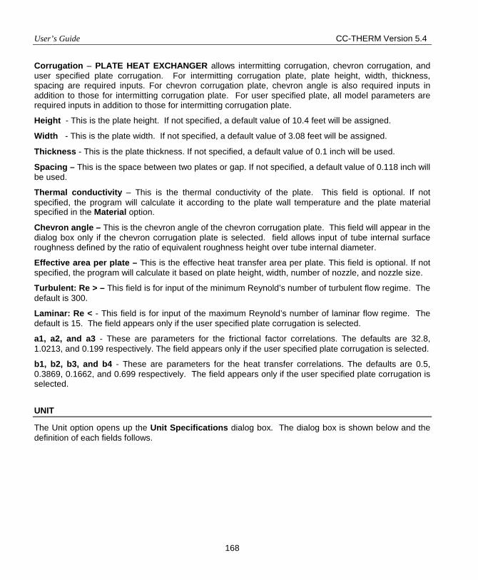
User’s Guide CC-THERM Version 5.4
168
Corrugation – PLATE HEAT EXCHANGER allows intermitting corrugation, chevron corrugation, and user specified plate corrugation. For intermitting corrugation plate, plate height, width, thickness, spacing are required inputs. For chevron corrugation plate, chevron angle is also required inputs in addition to those for intermitting corrugation plate. For user specified plate, all model parameters are required inputs in addition to those for intermitting corrugation plate.
Height - This is the plate height. If not specified, a default value of 10.4 feet will be assigned.
Width - This is the plate width. If not specified, a default value of 3.08 feet will be assigned.
Thickness - This is the plate thickness. If not specified, a default value of 0.1 inch will be used.
Spacing – This is the space between two plates or gap. If not specified, a default value of 0.118 inch will be used.
Thermal conductivity – This is the thermal conductivity of the plate. This field is optional. If not specified, the program will calculate it according to the plate wall temperature and the plate material specified in the Material option.
Chevron angle – This is the chevron angle of the chevron corrugation plate. This field will appear in the dialog box only if the chevron corrugation plate is selected. field allows input of tube internal surface roughness defined by the ratio of equivalent roughness height over tube internal diameter.
Effective area per plate – This is the effective heat transfer area per plate. This field is optional. If not specified, the program will calculate it based on plate height, width, number of nozzle, and nozzle size.
Turbulent: Re > – This field is for input of the minimum Reynold’s number of turbulent flow regime. The default is 300.
Laminar: Re < - This field is for input of the maximum Reynold’s number of laminar flow regime. The default is 15. The field appears only if the user specified plate corrugation is selected.
a1, a2, and a3 - These are parameters for the frictional factor correlations. The defaults are 32.8, 1.0213, and 0.199 respectively. The field appears only if the user specified plate corrugation is selected.
b1, b2, b3, and b4 - These are parameters for the heat transfer correlations. The defaults are 0.5, 0.3869, 0.1662, and 0.699 respectively. The field appears only if the user specified plate corrugation is selected.
UNIT
The Unit option opens up the Unit Specifications dialog box. The dialog box is shown below and the definition of each fields follows.
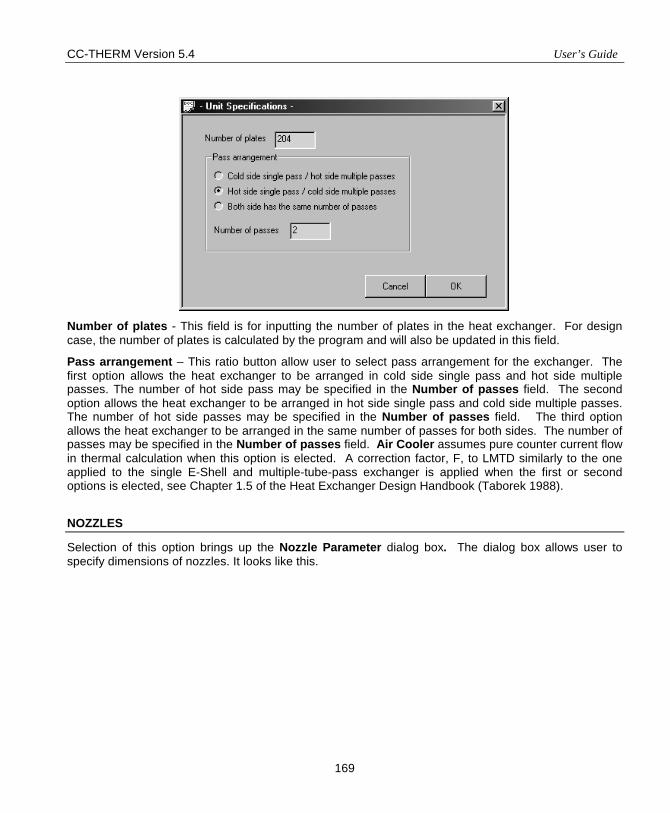
CC-THERM Version 5.4 User’s Guide
169
Number of plates - This field is for inputting the number of plates in the heat exchanger. For design case, the number of plates is calculated by the program and will also be updated in this field.
Pass arrangement – This ratio button allow user to select pass arrangement for the exchanger. The first option allows the heat exchanger to be arranged in cold side single pass and hot side multiple passes. The number of hot side pass may be specified in the Number of passes field. The second option allows the heat exchanger to be arranged in hot side single pass and cold side multiple passes. The number of hot side passes may be specified in the Number of passes field. The third option allows the heat exchanger to be arranged in the same number of passes for both sides. The number of passes may be specified in the Number of passes field. Air Cooler assumes pure counter current flow in thermal calculation when this option is elected. A correction factor, F, to LMTD similarly to the one applied to the single E-Shell and multiple-tube-pass exchanger is applied when the first or second options is elected, see Chapter 1.5 of the Heat Exchanger Design Handbook (Taborek 1988).
NOZZLES
Selection of this option brings up the Nozzle Parameter dialog box. The dialog box allows user to specify dimensions of nozzles. It looks like this.
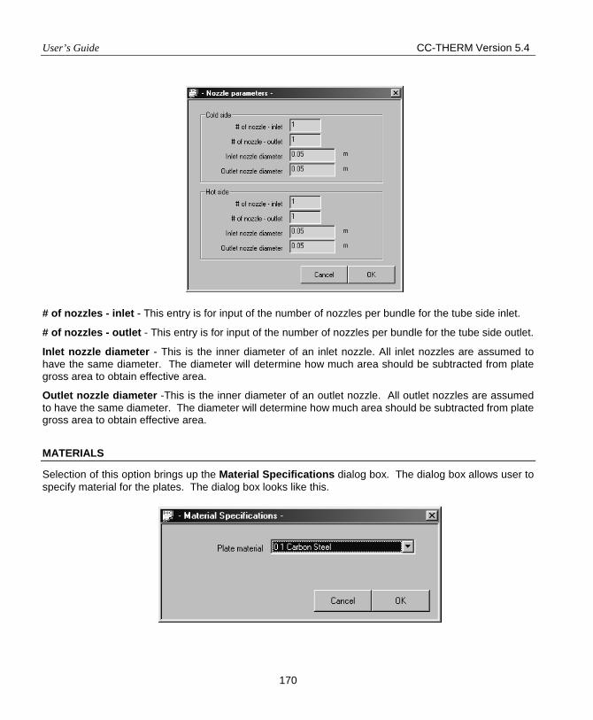
User’s Guide CC-THERM Version 5.4
170
# of nozzles - inlet - This entry is for input of the number of nozzles per bundle for the tube side inlet.
# of nozzles - outlet - This entry is for input of the number of nozzles per bundle for the tube side outlet.
Inlet nozzle diameter - This is the inner diameter of an inlet nozzle. All inlet nozzles are assumed to have the same diameter. The diameter will determine how much area should be subtracted from plate gross area to obtain effective area.
Outlet nozzle diameter -This is the inner diameter of an outlet nozzle. All outlet nozzles are assumed to have the same diameter. The diameter will determine how much area should be subtracted from plate gross area to obtain effective area.
MATERIALS
Selection of this option brings up the Material Specifications dialog box. The dialog box allows user to specify material for the plates. The dialog box looks like this.
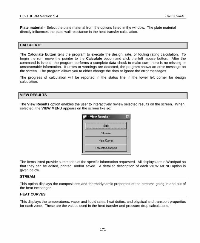
CC-THERM Version 5.4 User’s Guide
171
Plate material - Select the plate material from the options listed in the window. The plate material directly influences the plate wall resistance in the heat transfer calculation.
CALCULATE
The Calculate button tells the program to execute the design, rate, or fouling rating calculation. To begin the run, move the pointer to the Calculate option and click the left mouse button. After the command is issued, the program performs a complete data check to make sure there is no missing or unreasonable information. If errors or warnings are detected, the program shows an error message on the screen. The program allows you to either change the data or ignore the error messages.
The progress of calculation will be reported in the status line in the lower left corner for design calculation.
VIEW RESULTS
The View Results option enables the user to interactively review selected results on the screen. When selected, the VIEW MENU appears on the screen like so: The items listed provide summaries of the specific information requested. All displays are in Wordpad so that they can be edited, printed, and/or saved. A detailed description of each VIEW MENU option is given below.
STREAM
This option displays the compositions and thermodynamic properties of the streams going in and out of the heat exchanger.
HEAT CURVES
This displays the temperatures, vapor and liquid rates, heat duties, and physical and transport properties for each zone. These are the values used in the heat transfer and pressure drop calculations.
User’s Guide CC-THERM Version 5.4
172
TABULATED DATA
This option displays the Overall Data, Cold Side Data, Hot Side Data, Unit, Cold Side Nozzles, Hot Side Nozzles and General Specification together on one page.
RE-ENTER STREAM INFORMATION
This command allows user to retrieve new streams from CHEMCAD flow sheet. This is very useful in case any stream entering or exiting the exchanger is changed.
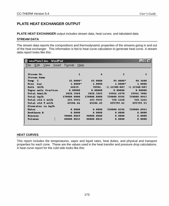
CC-THERM Version 5.4 User’s Guide
173
PLATE HEAT EXCHANGER OUTPUT
PLATE HEAT EXCHANGER output includes stream data, heat curves, and tabulated data.
STREAM DATA
The stream data reports the compositions and thermodynamic properties of the streams going in and out of the heat exchanger. This information is fed to heat curve calculation to generate heat curve. A stream data report looks like this:
HEAT CURVES
This report includes the temperatures, vapor and liquid rates, heat duties, and physical and transport properties for each zone. These are the values used in the heat transfer and pressure drop calculations. A heat curve report for the cold side looks like this:
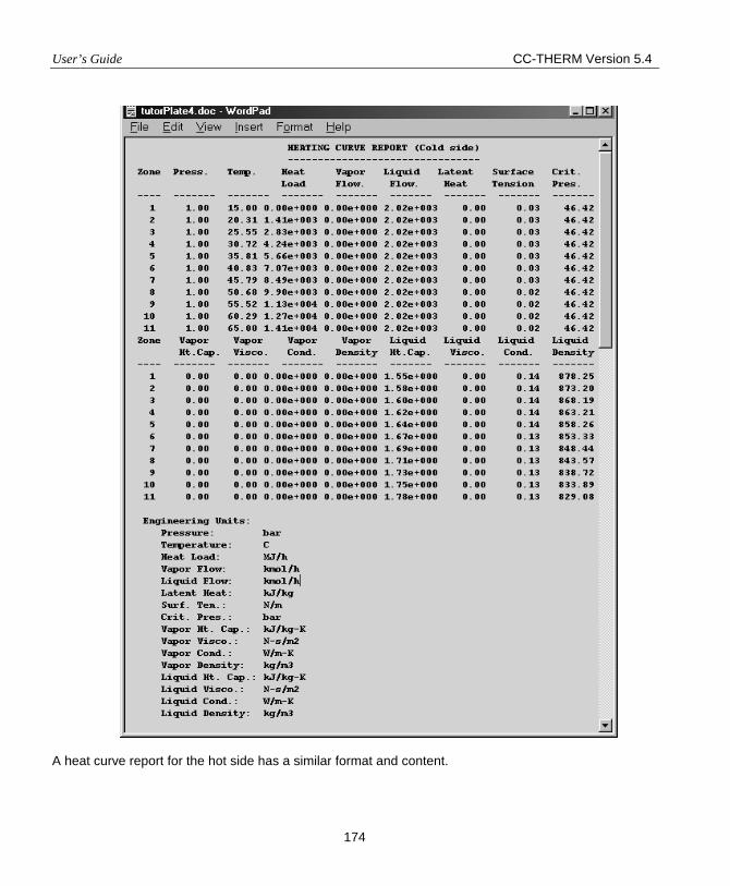
User’s Guide CC-THERM Version 5.4
174
A heat curve report for the hot side has a similar format and content.
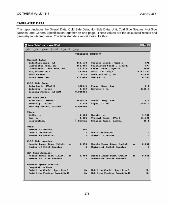
CC-THERM Version 5.4 User’s Guide
175
TABULATED DATA
This report includes the Overall Data, Cold Side Data, Hot Side Data, Unit, Cold Side Nozzles, Hot Side Nozzles, and General Specification together on one page. These values are the calculated results and geometry inputs from user. The tabulated data report looks like this:
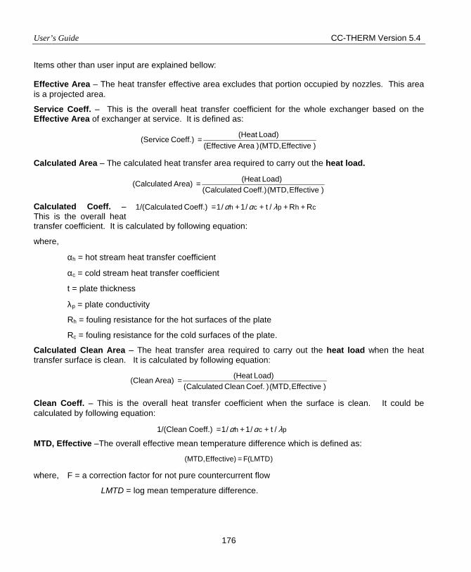
User’s Guide CC-THERM Version 5.4
176
Items other than user input are explained bellow: Effective Area – The heat transfer effective area excludes that portion occupied by nozzles. This area is a projected area.
Service Coeff. – This is the overall heat transfer coefficient for the whole exchanger based on the Effective Area of exchanger at service. It is defined as:
) EffectiveMTD,() AreaEffective( Load) (Heat Coeff.) (Service =
Calculated Area – The calculated heat transfer area required to carry out the heat load.
) EffectiveMTD,()Coeff. Calculated( Load) (Heat Area)d(Calculate =
Calculated Coeff. – This is the overall heat transfer coefficient. It is calculated by following equation:
where,
αh = hot stream heat transfer coefficient
αc = cold stream heat transfer coefficient
t = plate thickness
λp = plate conductivity
Rh = fouling resistance for the hot surfaces of the plate
Rc = fouling resistance for the cold surfaces of the plate.
Calculated Clean Area – The heat transfer area required to carry out the heat load when the heat transfer surface is clean. It is calculated by following equation:
) EffectiveMTD,() Coef. Clean Calculated( Load) (Heat Area)(Clean =
Clean Coeff. – This is the overall heat transfer coefficient when the surface is clean. It could be calculated by following equation:
MTD, Effective –The overall effective mean temperature difference which is defined as:
)LMTD(FEffective)(MTD, =
where, F = a correction factor for not pure countercurrent flow
LMTD = log mean temperature difference.
chpch RR/t/1/1 Coeff.) ted1/(Calcula ++++= λαα
pch /t/1/1 Coeff.) 1/(Clean λαα ++=
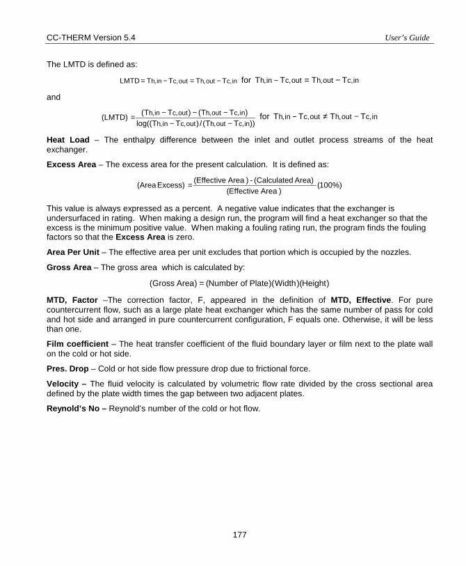
CC-THERM Version 5.4 User’s Guide
177
The LMTD is defined as:
in,cout,hout,cin,h TTTTLMTD −=−= for in,cout,hout,cin,h TTTT −=−
and
))TT(/)TTlog(( )TT()TT( (LMTD)
in,cout,hout,cin,hin,cout,hout,cin,h
−−−−−= for in,cout,hout,cin,h TTTT −≠−
Heat Load – The enthalpy difference between the inlet and outlet process streams of the heat exchanger.
Excess Area – The excess area for the present calculation. It is defined as:
%)100() AreaEffective(
Area)d(Calculate - ) Area(Effective Excess) (Area =
This value is always expressed as a percent. A negative value indicates that the exchanger is undersurfaced in rating. When making a design run, the program will find a heat exchanger so that the excess is the minimum positive value. When making a fouling rating run, the program finds the fouling factors so that the Excess Area is zero.
Area Per Unit – The effective area per unit excludes that portion which is occupied by the nozzles.
Gross Area – The gross area which is calculated by:
)Height)(Width)(Plate of Number()Area Gross( =
MTD, Factor –The correction factor, F, appeared in the definition of MTD, Effective. For pure countercurrent flow, such as a large plate heat exchanger which has the same number of pass for cold and hot side and arranged in pure countercurrent configuration, F equals one. Otherwise, it will be less than one.
Film coefficient – The heat transfer coefficient of the fluid boundary layer or film next to the plate wall on the cold or hot side.
Pres. Drop – Cold or hot side flow pressure drop due to frictional force.
Velocity – The fluid velocity is calculated by volumetric flow rate divided by the cross sectional area defined by the plate width times the gap between two adjacent plates.
Reynold’s No – Reynold’s number of the cold or hot flow.
User’s Guide CC-THERM Version 5.4
178
APPENDIX I PLATE HEAT EXCHANGER REFERENCES
P1 Kumar, H., Performance. In Heat Exchanger Design Handbook; Schlunder E. U., Beaton C. F., Bell K. J., et al., Hemisphere Publishing Corporation: New York, 1988, Chap. 3.7.3.
P2 Taborek J., Charts for mean temperature difference in industrial heat exchanger congigurations. In Heat Exchanger Design Handbook; Schlunder E. U., Beaton C. F., Bell K. J., et al., Hemisphere Publishing Corporation: New York, 1988, Chap. 1.5.
CC-THERM
DOUBLE PIPE
User’s Guide And Tutorial

CC-THERM Version 5.4 User’s Guide
179
PRODUCT OVERVIEW
INTRODUCTION TO CC-THERM DOUBLE PIPE
CC-THERM DOUBLE PIPE or DOUBLE PIPE is an integrated module for rating, design, simulation, and fouling rating of double pipe heat exchangers in the CHEMCAD system. DOUBLE PIPE is fully integrated with CHEMCAD so process data is automatically transferred from the process flowsheets to the heat exchanger analysis, and heating curves and physical properties data are automatically generated using the same properties and methods.
EASY TO LEARN
The input for DOUBLE PIPE is simple and concise. It is based upon the CHEMCAD input system, so anyone familiar with CHEMCAD will be able to operate DOUBLE PIPE with ease.
Since the input/output systems and conventions are the same in DOUBLE PIPE as those used in CHEMCAD, please refer to the CHEMCAD User’s Guide for these types of “How to” instructions.
TECHNICAL FEATURES
1. DOUBLE PIPE handles the applications of sensible heat transfer for both liquid and vapor.
2. Four modes of calculation may be selected: Rating, design, simulation, fouling rating mode.
3. Standard double pipe exchanger from Brown Fintube company.
4. Single and multiple modules in parallel and/or series.
5. Tubes may be bare or longitudinal fin, straight or U-shaped. A library of longitudinal finned tube from Brown Fintube company is built into the program.
6. Single and multiple tubes in one shell.
HEAT TRANSFER METHODS
SENSIBLE HEAT TRANSFER
Sensible Flow – Tubeside: The Sieder-Tate, Colburn, Dittus-Boelter, or ESDU method can be selected in for the calculation of the tubeside heat transfer coefficient in the turbulent region. The method of Eubank-Proctor or VDI Mean Nusselt Number may be used for laminar flow. The flow is assumed to be laminar below a Reynolds number of 2000 and is turbulent above a Reynolds number of 4000. In the transition region, the program prorates the laminar and turbulent coefficient according to the Reynolds number to arrive at the final coefficient.
User’s Guide CC-THERM Version 5.4
180
The Blasius method may be selected for the frictional factor in the pressure drop calculation for turbulent flow with smooth tube internal surface while Chen method is available for rough surface. If the flow is in the transient region where Reynolds number is greater than 2300 and less than 20000, the Blasius equation is used.
Sensible Flow – Shellside: For the heat transfer coefficient at the inner surface of the annulus, or shell side, the method recommend in the book by Hewitt, et al. is used for laminar flow with bare tube. For turbulent flow, same options are available as for tube side.
For finned tube, VDI-Mean Nusselt Number method of heat transfer cofficient is used for laminar flow in the channels between fins. For turbulent flow heat transfer coefficient and frictional factor in the pressure drop calculation, same options as for tube side are available.
THE ZONE ANALYSIS
The unit is analyzed using n (default =10) zones. DOUBLE PIPE automatically sets up the zones and properties of each zone, but permits the user to edit or override.
OUTPUT FEATURES
The user may select from the following output reports:
• A zone-by-zone print-out of the heat curve and fluid physical properties • The TEMA sheet • A tabulated print-out of overall exchanger values • A zone-by-zone print-out of heat transfer and pressure drop calculations • Inlet and outlet stream information • Plot of heat curve, heat flux, LMTD, temperature, coefficient, and area.
In addition to obtaining a hardcopy output report, you can review the results interactively on the screen and graphically using the plot features of the program.
OVERVIEW
DOUBLE PIPE is an interactive simulation tool for the design, rating, simulation, or fouling rating of double pipe heat exchangers. This section gives an overall view of the program usage and the options available on the DOUBLE PIPE menu. More information on each option is provided in later sections. The input functions allow you to enter process data by using dialog boxes with context specific help. With this input facility, you can create new problem files, review the results of problems already designed, and make modifications to previously saved problems.
There are seven general steps involved in running a heat exchanger design, rating, or fouling rating with CC-THERM DOUBLE PIPE. The following list illustrates the general steps.
CC-THERM Version 5.4 User’s Guide
181
1. Define the problem and run the flowsheet in CC-STEADY STATE. This generates CHEMCAD files.
2. Select the Sizing command on the menu bar. The Sizing menu will open.
3. From this menu select the Heat Exchangers and then Double Pipe.
4. The program will prompt you through the initial setup of the exchanger analysis. It will do this by displaying instructions about what you are to do next. When the instruction is cleared (by clicking [OK]), you will be taken to the function or dialog box appropriate for completing the instructed task. At the end of the setup process, the DOUBLE PIPE menu is displayed.
5. Inspect and edit the input as desired using the menu commands.
6. Execute the program.
7. Review and printout the results.
Similarly, there are seven general steps involved in running a heat exchanger simulation with DOUBLE PIPE. The following list illustrates the general steps.
1. Define only input streams of the heat exchanger in CHEMCAD. Please note that one-sided heat exchanger could not be used with DOUBLE PIPE simulation mode.
2. Select Edit UnitOp Data. The heat exchanger (HTXR) – dialog box will open.
3. From this box, select 5. Double Pipe simulation option for the simulation mode and click on [OK] button.
4. The program will prompt you through the initial setup of the exchanger analysis. It will do this by displaying instructions about what you are to do next. When the instruction is cleared (by clicking [OK]), you will be taken to the function or dialog box appropriate for completing the instructed task. At the end of the setup process, the DOUBLE PIPE menu is displayed.
5. Inspect and edit the input as desired using the menu commands. Exit the menu and save all the data entry.
6. Run simulation as you do for other UnitOp in CC-STEADY STATE.
7. Review and printout the results in CHEMCAD as you do for other UnitOp or go to CC-THERM to do review and printout the results.
The program performs the following tasks.
1. Performs extensive error checking.
2. Creates the streams if one-sided heat exchanger is used.
3. Generates the heat curve for the tube and shell sides.
4. Performs the design, rating, simulation, fouling rating studies. In the design mode, the user needs to specify all the basic information about the configuration of a single heat exchanger and the program will run optimization so that the smallest numbers of heat exchangers in parallel and series are found which satisfies all design criteria. In the rating mode, you must provide all the basic
User’s Guide CC-THERM Version 5.4
182
information about the exchanger configuration and the program will check and rate the exchanger for its adequacy in the service specified. In the simulation mode, you must provide all the basic information about the exchanger configuration and the program will calculate the output steams for the specified heat exchangers. In the fouling rating mode, you must provide all the basic information about the exchanger configuration except the fouling factor which will be estimated by the program.
5. Generates the output for the design, rating, simulation, or fouling rating of the heat exchanger.
6. Provides an interactive user interface to allow the user to change the problem specifications to rerun the problem and review the results.
7. Creates the DOUBLE PIPE files to save all the input/output data for each exchanger.
SUMMARY
As an integrated module to the CHEMCAD Suite, DOUBLE PIPE offers the process engineer an easy and comprehensive method of rating, design, simulating, and fouling rating double pipe heat exchangers. Since it uses the same command language as CHEMCAD, any CHEMCAD user can pick up the program in a matter of minutes. The program has been thoroughly tested against hand calculations and found to be an accurate and reliable tool. It is fully supported by a staff of trained engineers.
DOUBLE PIPE COMMANDS
To run a heat exchanger calculation in CHEMCAD you must access the DOUBLE PIPE menu. This menu provides a set of commands, which are used to setup, run, review, and print out the analysis. This section describes the use of those commands in detail.
For design, rating, and fouling rating, the following procedure is used to call the DOUBLE PIPE menu:
1. Run a simulation of a flowsheet containing a heat exchanger. CC-THERM DOUBLE PIPE must have a heat and material balance around the unit before it can rate it.
2. Select the Sizing command from the menu bar. The Sizing menu will open.
3. Select the Heat Exchangers > Double Pipe option from the Sizing menu.
4. If a heat exchanger is not currently “selected”, the program will ask you to select one to be rated. If a heat exchanger is currently “selected” on the flowsheet, the program will assume this is the unit you want to analyze.
5. If the selected heat exchanger has never been analyzed before, the program will let you select heat exchanger category. After select Double pipe heat exchanger option, CC-THERM will walk you through the input procedure. This will involve identifying the tubeside stream (the shellside stream is then inferred) and completing a series of dialog boxes. Once these have been completed (or at least viewed), the DOUBLE PIPE menu will appear.

CC-THERM Version 5.4 User’s Guide
179
PRODUCT OVERVIEW
INTRODUCTION TO CC-THERM DOUBLE PIPE
CC-THERM DOUBLE PIPE or DOUBLE PIPE is an integrated module for rating, design, simulation, and fouling rating of double pipe heat exchangers in the CHEMCAD system. DOUBLE PIPE is fully integrated with CHEMCAD so process data is automatically transferred from the process flowsheets to the heat exchanger analysis, and heating curves and physical properties data are automatically generated using the same properties and methods.
EASY TO LEARN
The input for DOUBLE PIPE is simple and concise. It is based upon the CHEMCAD input system, so anyone familiar with CHEMCAD will be able to operate DOUBLE PIPE with ease.
Since the input/output systems and conventions are the same in DOUBLE PIPE as those used in CHEMCAD, please refer to the CHEMCAD User’s Guide for these types of “How to” instructions.
TECHNICAL FEATURES
1. DOUBLE PIPE handles the applications of sensible heat transfer for both liquid and vapor.
2. Four modes of calculation may be selected: Rating, design, simulation, fouling rating mode.
3. Standard double pipe exchanger from Brown Fintube company.
4. Single and multiple modules in parallel and/or series.
5. Tubes may be bare or longitudinal fin, straight or U-shaped. A library of longitudinal finned tube from Brown Fintube company is built into the program.
6. Single and multiple tubes in one shell.
HEAT TRANSFER METHODS
SENSIBLE HEAT TRANSFER
Sensible Flow – Tubeside: The Sieder-Tate, Colburn, Dittus-Boelter, or ESDU method can be selected in for the calculation of the tubeside heat transfer coefficient in the turbulent region. The method of Eubank-Proctor or VDI Mean Nusselt Number may be used for laminar flow. The flow is assumed to be laminar below a Reynolds number of 2000 and is turbulent above a Reynolds number of 4000. In the transition region, the program prorates the laminar and turbulent coefficient according to the Reynolds number to arrive at the final coefficient.

User’s Guide CC-THERM Version 5.4
180
The Blasius method may be selected for the frictional factor in the pressure drop calculation for turbulent flow with smooth tube internal surface while Chen method is available for rough surface. If the flow is in the transient region where Reynolds number is greater than 2300 and less than 20000, the Blasius equation is used.
Sensible Flow – Shellside: For the heat transfer coefficient at the inner surface of the annulus, or shell side, the method recommend in the book by Hewitt, et al. is used for laminar flow with bare tube. For turbulent flow, same options are available as for tube side.
For finned tube, VDI-Mean Nusselt Number method of heat transfer cofficient is used for laminar flow in the channels between fins. For turbulent flow heat transfer coefficient and frictional factor in the pressure drop calculation, same options as for tube side are available.
THE ZONE ANALYSIS
The unit is analyzed using n (default =10) zones. DOUBLE PIPE automatically sets up the zones and properties of each zone, but permits the user to edit or override.
OUTPUT FEATURES
The user may select from the following output reports:
• A zone-by-zone print-out of the heat curve and fluid physical properties • The TEMA sheet • A tabulated print-out of overall exchanger values • A zone-by-zone print-out of heat transfer and pressure drop calculations • Inlet and outlet stream information • Plot of heat curve, heat flux, LMTD, temperature, coefficient, and area.
In addition to obtaining a hardcopy output report, you can review the results interactively on the screen and graphically using the plot features of the program.
OVERVIEW
DOUBLE PIPE is an interactive simulation tool for the design, rating, simulation, or fouling rating of double pipe heat exchangers. This section gives an overall view of the program usage and the options available on the DOUBLE PIPE menu. More information on each option is provided in later sections. The input functions allow you to enter process data by using dialog boxes with context specific help. With this input facility, you can create new problem files, review the results of problems already designed, and make modifications to previously saved problems.
There are seven general steps involved in running a heat exchanger design, rating, or fouling rating with CC-THERM DOUBLE PIPE. The following list illustrates the general steps.

CC-THERM Version 5.4 User’s Guide
181
1. Define the problem and run the flowsheet in CC-STEADY STATE. This generates CHEMCAD files.
2. Select the Sizing command on the menu bar. The Sizing menu will open.
3. From this menu select the Heat Exchangers and then Double Pipe.
4. The program will prompt you through the initial setup of the exchanger analysis. It will do this by displaying instructions about what you are to do next. When the instruction is cleared (by clicking [OK]), you will be taken to the function or dialog box appropriate for completing the instructed task. At the end of the setup process, the DOUBLE PIPE menu is displayed.
5. Inspect and edit the input as desired using the menu commands.
6. Execute the program.
7. Review and printout the results.
Similarly, there are seven general steps involved in running a heat exchanger simulation with DOUBLE PIPE. The following list illustrates the general steps.
1. Define only input streams of the heat exchanger in CHEMCAD. Please note that one-sided heat exchanger could not be used with DOUBLE PIPE simulation mode.
2. Select Edit UnitOp Data. The heat exchanger (HTXR) – dialog box will open.
3. From this box, select 5. Double Pipe simulation option for the simulation mode and click on [OK] button.
4. The program will prompt you through the initial setup of the exchanger analysis. It will do this by displaying instructions about what you are to do next. When the instruction is cleared (by clicking [OK]), you will be taken to the function or dialog box appropriate for completing the instructed task. At the end of the setup process, the DOUBLE PIPE menu is displayed.
5. Inspect and edit the input as desired using the menu commands. Exit the menu and save all the data entry.
6. Run simulation as you do for other UnitOp in CC-STEADY STATE.
7. Review and printout the results in CHEMCAD as you do for other UnitOp or go to CC-THERM to do review and printout the results.
The program performs the following tasks.
1. Performs extensive error checking.
2. Creates the streams if one-sided heat exchanger is used.
3. Generates the heat curve for the tube and shell sides.
4. Performs the design, rating, simulation, fouling rating studies. In the design mode, the user needs to specify all the basic information about the configuration of a single heat exchanger and the program will run optimization so that the smallest numbers of heat exchangers in parallel and series are found which satisfies all design criteria. In the rating mode, you must provide all the basic

User’s Guide CC-THERM Version 5.4
182
information about the exchanger configuration and the program will check and rate the exchanger for its adequacy in the service specified. In the simulation mode, you must provide all the basic information about the exchanger configuration and the program will calculate the output steams for the specified heat exchangers. In the fouling rating mode, you must provide all the basic information about the exchanger configuration except the fouling factor which will be estimated by the program.
5. Generates the output for the design, rating, simulation, or fouling rating of the heat exchanger.
6. Provides an interactive user interface to allow the user to change the problem specifications to rerun the problem and review the results.
7. Creates the DOUBLE PIPE files to save all the input/output data for each exchanger.
SUMMARY
As an integrated module to the CHEMCAD Suite, DOUBLE PIPE offers the process engineer an easy and comprehensive method of rating, design, simulating, and fouling rating double pipe heat exchangers. Since it uses the same command language as CHEMCAD, any CHEMCAD user can pick up the program in a matter of minutes. The program has been thoroughly tested against hand calculations and found to be an accurate and reliable tool. It is fully supported by a staff of trained engineers.
DOUBLE PIPE COMMANDS
To run a heat exchanger calculation in CHEMCAD you must access the DOUBLE PIPE menu. This menu provides a set of commands, which are used to setup, run, review, and print out the analysis. This section describes the use of those commands in detail.
For design, rating, and fouling rating, the following procedure is used to call the DOUBLE PIPE menu:
1. Run a simulation of a flowsheet containing a heat exchanger. CC-THERM DOUBLE PIPE must have a heat and material balance around the unit before it can rate it.
2. Select the Sizing command from the menu bar. The Sizing menu will open.
3. Select the Heat Exchangers > Double Pipe option from the Sizing menu.
4. If a heat exchanger is not currently “selected”, the program will ask you to select one to be rated. If a heat exchanger is currently “selected” on the flowsheet, the program will assume this is the unit you want to analyze.
5. If the selected heat exchanger has never been analyzed before, the program will let you select heat exchanger category. After select Double pipe heat exchanger option, CC-THERM will walk you through the input procedure. This will involve identifying the tubeside stream (the shellside stream is then inferred) and completing a series of dialog boxes. Once these have been completed (or at least viewed), the DOUBLE PIPE menu will appear.
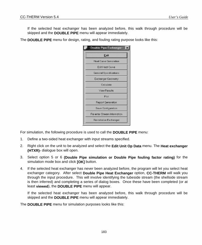
CC-THERM Version 5.4 User’s Guide
183
If the selected heat exchanger has been analyzed before, this walk through procedure will be skipped and the DOUBLE PIPE menu will appear immediately.
The DOUBLE PIPE menu for design, rating, and fouling rating purpose looks like this:
For simulation, the following procedure is used to call the DOUBLE PIPE menu:
1. Define a two-sided heat exchanger with input streams specified.
2. Right click on the unit to be analyzed and select the Edit Unit Op Data menu. The Heat exchanger (HTXR)- dialogue box will open.
3. Select option 5 or 6 (Double Pipe simulation or Double Pipe fouling factor rating) for the simulation mode box and click [OK] button.
4. If the selected heat exchanger has never been analyzed before, the program will let you select heat exchanger category. After select Double Pipe Heat Exchanger option, CC-THERM will walk you through the input procedure. This will involve identifying the tubeside stream (the shellside stream is then inferred) and completing a series of dialog boxes. Once these have been completed (or at least viewed), the DOUBLE PIPE menu will appear.
If the selected heat exchanger has been analyzed before, this walk through procedure will be skipped and the DOUBLE PIPE menu will appear immediately.
The DOUBLE PIPE menu for simulation purposes looks like this:
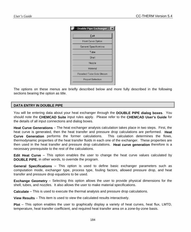
User’s Guide CC-THERM Version 5.4
184
The options on these menus are briefly described below and more fully described in the following sections bearing the option as title.
DATA ENTRY IN DOUBLE PIPE
You will be entering data about your heat exchanger through the DOUBLE PIPE dialog boxes. You should note the CHEMCAD Suite input rules apply. Please refer to the CHEMCAD User’s Guide for the details of all input connections and dialog boxes.
Heat Curve Generations – The heat exchanger analysis calculation takes place in two steps. First, the heat curve is generated, then the heat transfer and pressure drop calculations are performed. Heat Curve Generation performs the former calculations. This calculation determines the flows, thermodynamic properties of the heat transfer fluids in each one of the exchanger. These properties are then used in the heat transfer and pressure drop calculations. Heat curve generation therefore is a necessary prerequisite to the rest of the calculations.
Edit Heat Curve – This option enables the user to change the heat curve values calculated by DOUBLE PIPE, in other words, to override the program.
General Specifications – This option is used to define basic exchanger parameters such as computation mode, exchanger type, process type, fouling factors, allowed pressure drop, and heat transfer and pressure drop equations to be used.
Exchange Geometry – Selecting this option allows the user to provide physical dimensions for the shell, tubes, and nozzles. It also allows the user to make material specifications.
Calculate – This is used to execute the thermal analysis and pressure drop calculations.
View Results – This item is used to view the calculated results interactively.
Plot – This option enables the user to graphically display a variety of heat curves, heat flux, LMTD, temperature, heat transfer coefficient, and required heat transfer area on a zone-by-zone basis.
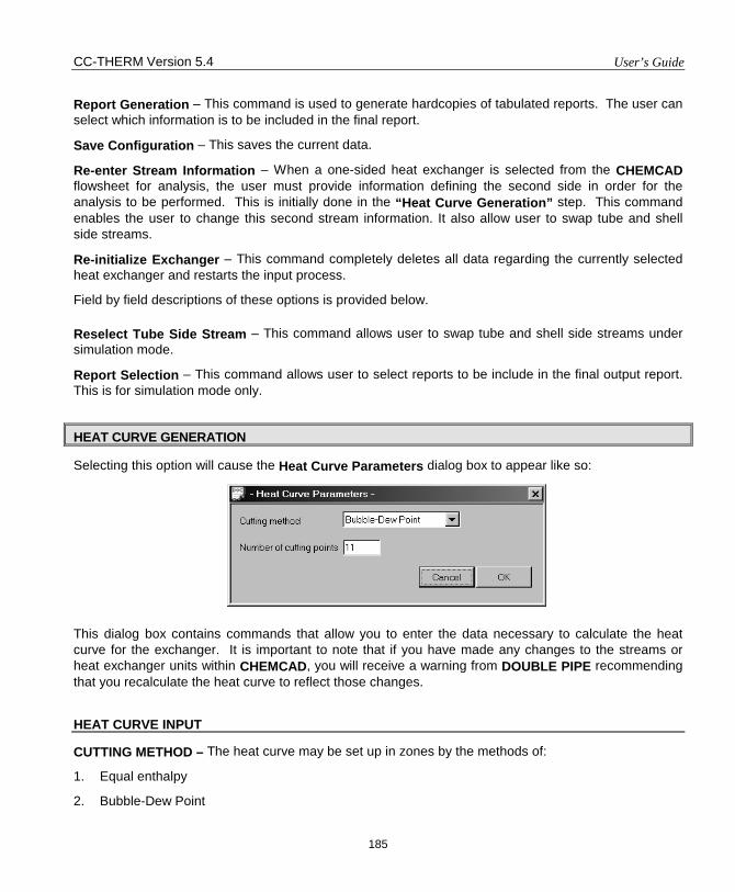
CC-THERM Version 5.4 User’s Guide
185
Report Generation – This command is used to generate hardcopies of tabulated reports. The user can select which information is to be included in the final report.
Save Configuration – This saves the current data.
Re-enter Stream Information – When a one-sided heat exchanger is selected from the CHEMCAD flowsheet for analysis, the user must provide information defining the second side in order for the analysis to be performed. This is initially done in the “Heat Curve Generation” step. This command enables the user to change this second stream information. It also allow user to swap tube and shell side streams.
Re-initialize Exchanger – This command completely deletes all data regarding the currently selected heat exchanger and restarts the input process.
Field by field descriptions of these options is provided below.
Reselect Tube Side Stream – This command allows user to swap tube and shell side streams under simulation mode.
Report Selection – This command allows user to select reports to be include in the final output report. This is for simulation mode only.
HEAT CURVE GENERATION
Selecting this option will cause the Heat Curve Parameters dialog box to appear like so:
This dialog box contains commands that allow you to enter the data necessary to calculate the heat curve for the exchanger. It is important to note that if you have made any changes to the streams or heat exchanger units within CHEMCAD, you will receive a warning from DOUBLE PIPE recommending that you recalculate the heat curve to reflect those changes.
HEAT CURVE INPUT
CUTTING METHOD – The heat curve may be set up in zones by the methods of:
1. Equal enthalpy
2. Bubble-Dew Point
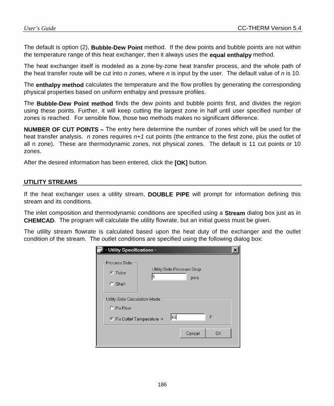
User’s Guide CC-THERM Version 5.4
186
The default is option (2), Bubble-Dew Point method. If the dew points and bubble points are not within the temperature range of this heat exchanger, then it always uses the equal enthalpy method.
The heat exchanger itself is modeled as a zone-by-zone heat transfer process, and the whole path of the heat transfer route will be cut into n zones, where n is input by the user. The default value of n is 10.
The enthalpy method calculates the temperature and the flow profiles by generating the corresponding physical properties based on uniform enthalpy and pressure profiles.
The Bubble-Dew Point method finds the dew points and bubble points first, and divides the region using these points. Further, it will keep cutting the largest zone in half until user specified number of zones is reached. For sensible flow, those two methods makes no significant difference.
NUMBER OF CUT POINTS – The entry here determine the number of zones which will be used for the heat transfer analysis. n zones requires n+1 cut points (the entrance to the first zone, plus the outlet of all n zone). These are thermodynamic zones, not physical zones. The default is 11 cut points or 10 zones.
After the desired information has been entered, click the [OK] button.
UTILITY STREAMS
If the heat exchanger uses a utility stream, DOUBLE PIPE will prompt for information defining this stream and its conditions.
The inlet composition and thermodynamic conditions are specified using a Stream dialog box just as in CHEMCAD. The program will calculate the utility flowrate, but an initial guess must be given.
The utility stream flowrate is calculated based upon the heat duty of the exchanger and the outlet condition of the stream. The outlet conditions are specified using the following dialog box:
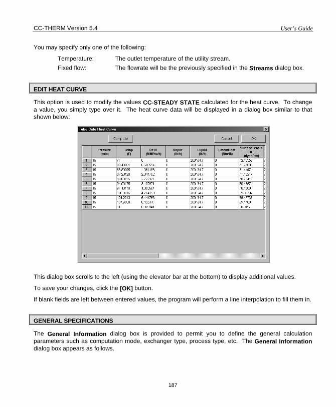
CC-THERM Version 5.4 User’s Guide
187
You may specify only one of the following:
Temperature: The outlet temperature of the utility stream. Fixed flow: The flowrate will be the previously specified in the Streams dialog box.
EDIT HEAT CURVE
This option is used to modify the values CC-STEADY STATE calculated for the heat curve. To change a value, you simply type over it. The heat curve data will be displayed in a dialog box similar to that shown below: This dialog box scrolls to the left (using the elevator bar at the bottom) to display additional values.
To save your changes, click the [OK] button.
If blank fields are left between entered values, the program will perform a line interpolation to fill them in.
GENERAL SPECIFICATIONS
The General Information dialog box is provided to permit you to define the general calculation parameters such as computation mode, exchanger type, process type, etc. The General Information dialog box appears as follows.
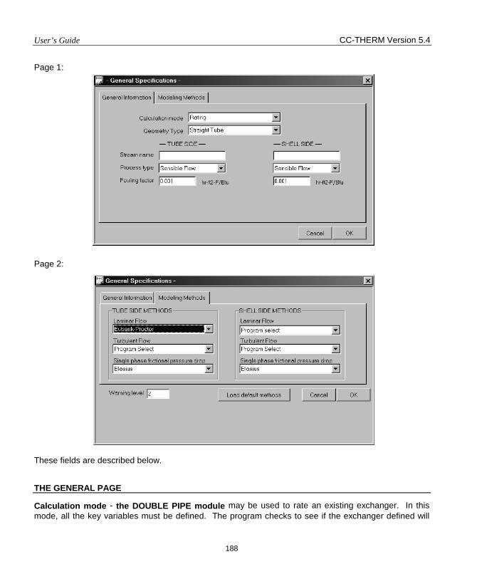
User’s Guide CC-THERM Version 5.4
188
Page 1: Page 2: These fields are described below.
THE GENERAL PAGE
Calculation mode - the DOUBLE PIPE module may be used to rate an existing exchanger. In this mode, all the key variables must be defined. The program checks to see if the exchanger defined will
CC-THERM Version 5.4 User’s Guide
189
work in the given application. You must define the geometry type, shell ID, tube length, number of exchangers in series and parallel.
Modular concept of double pipe heat exchanger lets you meet heat transfer duties and pressure drop constrains by putting together double pipe heat exchanger modules in series , parallel, or mixed fashion. Plant managers can immediately meet changing duties simply by rearranging, adding or subtracting modules. DOUBLE PIPE may be used to carry out thermal design for such task. In this mode, allowable pressure drops on both shell and tube side along with data needed for rating single module have to be specified. DOUBLE PIPE will calculate numbers of modules in series and parallel needed to meet the pressure drop constrains and heat duties.
DOUBLEPIPE may also be used to perform fouling rating. In this mode, all the geometry data of the heat exchanger must be defined and the program will estimate fouling factor(s) for given process flow data. This mode could be very useful for process engineer to estimated fouling situation of an on duty heat exchanger. There are three options under this mode; Rate tube side fouling, Rate shell side fouling, and Rate both side fouling. These options pop up on this page when fouling rating mode is selected. The program will assume equal fouling on tube and shell side while perform Rate both side fouling.
Geometry type - selection of straight tube or U shaped tube exchanger.
Process type – DOUBLE PIPE allows sensible flow on both tube and shell side.
Fouling factor - It is a thermal resistance included to account for the fouling. Its value is arbitrary and defines how often you want to clean the tubes. The default is 0.001 in English units on both sides.
THE METHODS PAGE
Tubeside Methods:
Tubeside Laminar Flow Method – This option defines which equation is to be used to calculate the sensible heat transfer film coefficient for laminar flow on the tubeside. The options are:
Eubank-Proctor Reference No. 1 APPENDIX II VDI Reference No. 2 APPENDIX II
Tubeside Turbulent Flow Method – This option specifies which method is to be used to calculate the tubeside film coefficient for sensible, turbulent flow on the tubeside, the options are:
Program Select: Let DOUBLE PIPE select the most appropriate method base upon the turbulent flow conditions.
Seader-Tate: Reference No. 3 APPENDIX II Colburn Method: Reference No. 4 APPENDIX II Dittus-Boelter: Reference No. 5 APPENDIX II ESDU Method: Reference No. 6 APPENDIX II Mean VDI Nusselt: Reference No. 7 APPENDIX II
User’s Guide CC-THERM Version 5.4
190
Tubeside Frictional Pressure Drop - This identifies the method to be used to calculate the tubeside frictional pressure drop. The options are:
The Blasius Equation
Reference No. 8 APPENDIX II
Chen’s Method Reference No. 9 APPENDIX II
Shellside Methods:
Shellside Laminar Flow Model - This option selects which method is to be used to calculate the shellside pressure drops and film coefficients for laminar flow. The options are:
Program Select: Let DOUBLE PIPE select the most appropriate method base upon the flow conditions.
Shellside Turbulent Flow Method – This option specifies which method is to be used to calculate the shellside film coefficient for sensible, turbulent flow on the shellside, the options are:
Program Select: Let DOUBLE PIPE select the most appropriate method base upon the flow conditions.
Seader-Tate: Reference No. 3 APPENDIX II Colburn Method: Reference No. 4 APPENDIX II Dittus-Boelter: Reference No. 5 APPENDIX II ESDU Method: Reference No. 6 APPENDIX II Mean VDI Nusselt: Reference No. 7 APPENDIX II
Shellside Frictional Pressure Drop - This identifies the method to be used to calculate the shellside frictional pressure drop. The options are:
The Blasius Equation
Reference No. 8 APPENDIX II
Chen’s Method Reference No. 9 APPENDIX II
The Load default methods button will load all default methods or setting on this page. Warning level controls pop up frequency of warning messages. The bigger the integer value is, the more frequent the messages will appear.
EXCHANGER GEOMETRY
The Exchanger Geometry option is to permit the user to make detailed specifications concerning the dimensions and arrangement of the heat exchanger.
Selecting this option will cause the Exchanger Geometry menu to appear like so:
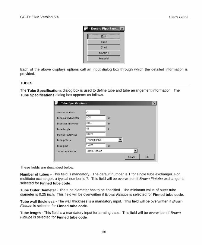
CC-THERM Version 5.4 User’s Guide
191
Each of the above displays options call an input dialog box through which the detailed information is provided.
TUBES
The Tube Specifications dialog box is used to define tube and tube arrangement information. The Tube Specifications dialog box appears as follows.
These fields are described below.
Number of tubes – This field is mandatory. The default number is 1 for single tube exchanger. For multitube exchanger, a typical number is 7. This field will be overwritten if Brown Fintube exchanger is selected for Finned tube code.
Tube Outer Diameter - The tube diameter has to be specified. The minimum value of outer tube diameter is 0.25 inch. This field will be overwritten if Brown Fintube is selected for Finned tube code.
Tube wall thickness - The wall thickness is a mandatory input. This field will be overwritten if Brown Fintube is selected for Finned tube code.
Tube length - This field is a mandatory input for a rating case. This field will be overwritten if Brown Fintube is selected for Finned tube code.
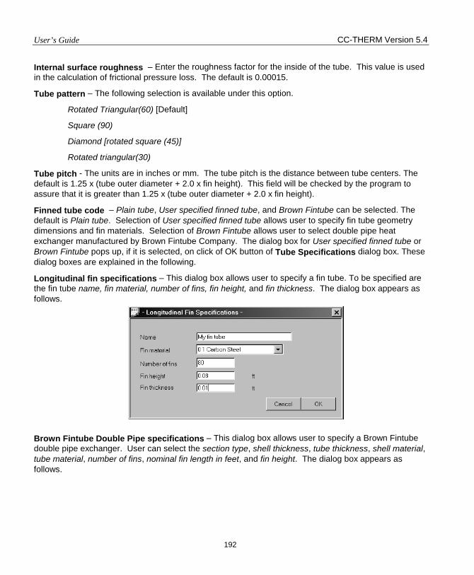
User’s Guide CC-THERM Version 5.4
192
Internal surface roughness – Enter the roughness factor for the inside of the tube. This value is used in the calculation of frictional pressure loss. The default is 0.00015.
Tube pattern – The following selection is available under this option.
Rotated Triangular(60) [Default]
Square (90)
Diamond [rotated square (45)]
Rotated triangular(30)
Tube pitch - The units are in inches or mm. The tube pitch is the distance between tube centers. The default is 1.25 x (tube outer diameter + 2.0 x fin height). This field will be checked by the program to assure that it is greater than 1.25 x (tube outer diameter + 2.0 x fin height).
Finned tube code – Plain tube, User specified finned tube, and Brown Fintube can be selected. The default is Plain tube. Selection of User specified finned tube allows user to specify fin tube geometry dimensions and fin materials. Selection of Brown Fintube allows user to select double pipe heat exchanger manufactured by Brown Fintube Company. The dialog box for User specified finned tube or Brown Fintube pops up, if it is selected, on click of OK button of Tube Specifications dialog box. These dialog boxes are explained in the following.
Longitudinal fin specifications – This dialog box allows user to specify a fin tube. To be specified are the fin tube name, fin material, number of fins, fin height, and fin thickness. The dialog box appears as follows.
Brown Fintube Double Pipe specifications – This dialog box allows user to specify a Brown Fintube double pipe exchanger. User can select the section type, shell thickness, tube thickness, shell material, tube material, number of fins, nominal fin length in feet, and fin height. The dialog box appears as follows.
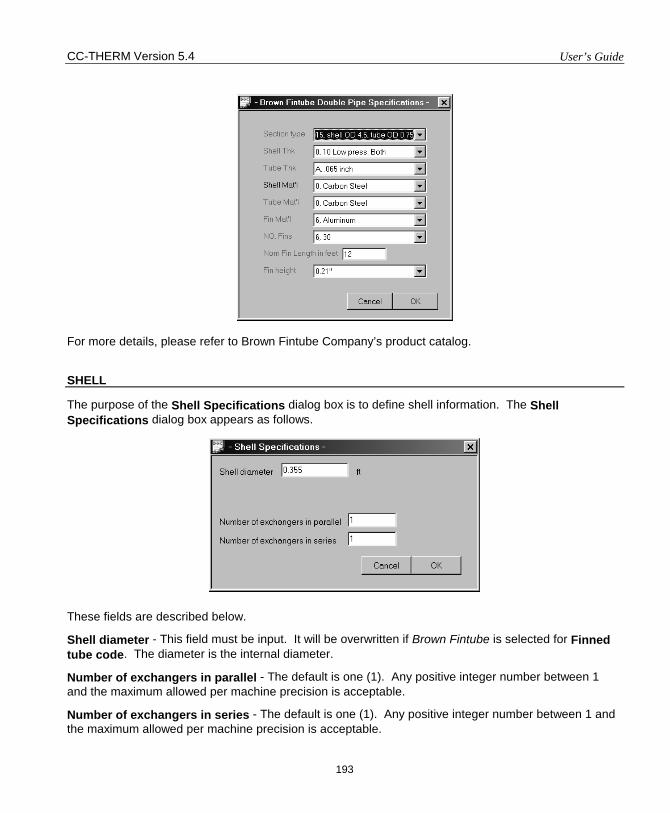
CC-THERM Version 5.4 User’s Guide
193
For more details, please refer to Brown Fintube Company’s product catalog.
SHELL
The purpose of the Shell Specifications dialog box is to define shell information. The Shell Specifications dialog box appears as follows.
These fields are described below.
Shell diameter - This field must be input. It will be overwritten if Brown Fintube is selected for Finned tube code. The diameter is the internal diameter.
Number of exchangers in parallel - The default is one (1). Any positive integer number between 1 and the maximum allowed per machine precision is acceptable.
Number of exchangers in series - The default is one (1). Any positive integer number between 1 and the maximum allowed per machine precision is acceptable.
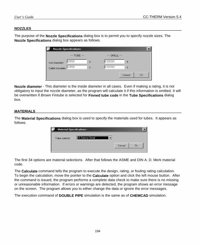
User’s Guide CC-THERM Version 5.4
194
NOZZLES
The purpose of the Nozzle Specifications dialog box is to permit you to specify nozzle sizes. The Nozzle Specifications dialog box appears as follows.
Nozzle diameter - This diameter is the inside diameter in all cases. Even if making a rating, it is not obligatory to input the nozzle diameter, as the program will calculate it if this information is omitted. It will be overwritten if Brown Fintube is selected for Finned tube code in the Tube Specifications dialog box.
MATERIALS
The Material Specifications dialog box is used to specify the materials used for tubes. It appears as follows.
The first 34 options are material selections. After that follows the ASME and DIN A. D. Merk material code.
The Calculate command tells the program to execute the design, rating, or fouling rating calculation. To begin the calculation, move the pointer to the Calculate option and click the left mouse button. After the command is issued, the program performs a complete data check to make sure there is no missing or unreasonable information. If errors or warnings are detected, the program shows an error message on the screen. The program allows you to either change the data or ignore the error messages.
The execution command of DOUBLE PIPE simulation is the same as of CHEMCAD simulation.
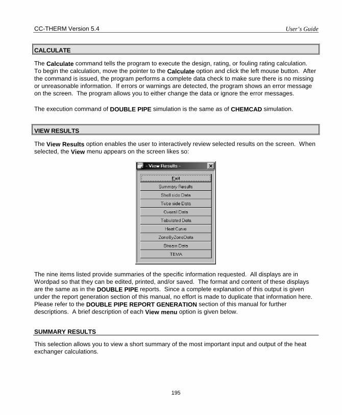
CC-THERM Version 5.4 User’s Guide
195
CALCULATE
The Calculate command tells the program to execute the design, rating, or fouling rating calculation. To begin the calculation, move the pointer to the Calculate option and click the left mouse button. After the command is issued, the program performs a complete data check to make sure there is no missing or unreasonable information. If errors or warnings are detected, the program shows an error message on the screen. The program allows you to either change the data or ignore the error messages.
The execution command of DOUBLE PIPE simulation is the same as of CHEMCAD simulation.
VIEW RESULTS
The View Results option enables the user to interactively review selected results on the screen. When selected, the View menu appears on the screen likes so:
The nine items listed provide summaries of the specific information requested. All displays are in Wordpad so that they can be edited, printed, and/or saved. The format and content of these displays are the same as in the DOUBLE PIPE reports. Since a complete explanation of this output is given under the report generation section of this manual, no effort is made to duplicate that information here. Please refer to the DOUBLE PIPE REPORT GENERATION section of this manual for further descriptions. A brief description of each View menu option is given below.
SUMMARY RESULTS
This selection allows you to view a short summary of the most important input and output of the heat exchanger calculations.
User’s Guide CC-THERM Version 5.4
196
SHELLSIDE DATA
This option shows the shellside data for the current exchanger. This includes velocity, film coefficient, Reynolds No., nozzles sizes, and pressure drops.
TUBESIDE DATA
This option shows the tubeside data for the current exchanger. This includes film coefficient, Reynolds No., pressure drops, nozzle sizes, and velocity.
OVERALL DATA
This option displays summary of the duty, area(s), heat transfer coefficient(s), and LMTD(s) of the heat exchanger.
TABULATED DATA
This option displays the Overall Data, Shellside Data, Tubeside Data, Tube Data, and Resistances Data together on one page.
HEAT CURVES
This displays the temperatures, vapor and liquid rates, heat duties, and physical and transport properties for each zone. These are the values used in the heat transfer and pressure drop calculations.
ZONE BY ZONE DATA
This option allows the user to review the zone-by-zone calculated results for both the tubeside and the shellside.
STREAM DATA
This option displays the compositions and thermodynamic properties of the streams going in and out of the heat exchanger.
TEMA SHEET
This option displays the completed TEMA sheet.
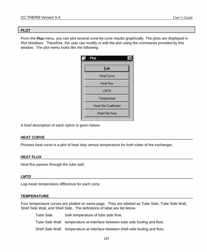
CC-THERM Version 5.4 User’s Guide
197
PLOT
From the Plot menu, you can plot several zone-by-zone results graphically. The plots are displayed in Plot Windows. Therefore, the user can modify or edit the plot using the commands provided by this window. The plot menu looks like the following. A brief description of each option is given below:
HEAT CURVE
Process heat curve is a plot of heat duty versus temperature for both sides of the exchanger.
HEAT FLUX
Heat flux passes through the tube wall.
LMTD
Log-mean temperature difference for each zone.
TEMPERATURE
Four temperature curves are plotted on same page. They are labeled as Tube Side, Tube Side Wall, Shell Side Wall, and Shell Side. The definitions of label are list below.
Tube Side: bulk temperature of tube side flow;
Tube Side Wall: temperature at interface between tube side fouling and flow;
Shell Side Wall: temperature at interface between shell side fouling and flow;
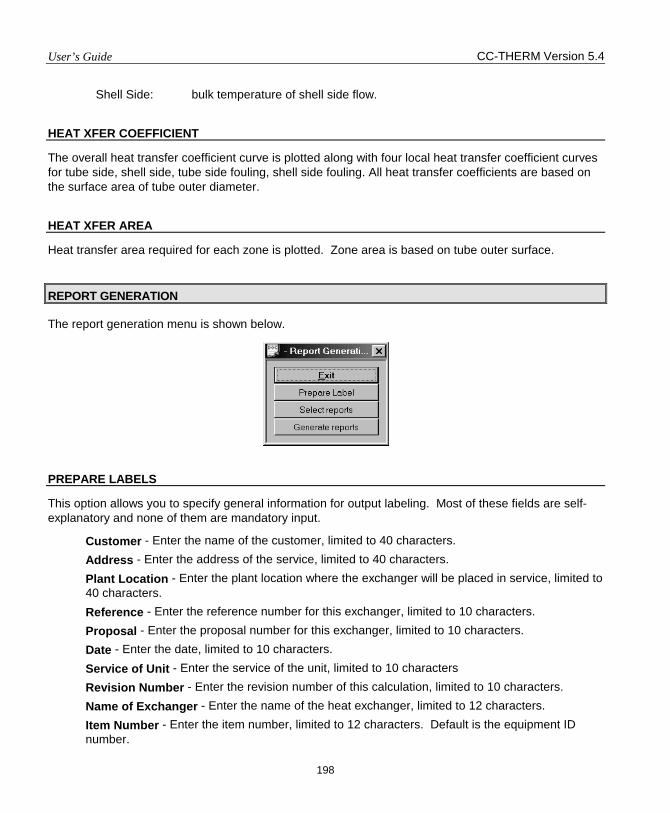
User’s Guide CC-THERM Version 5.4
198
Shell Side: bulk temperature of shell side flow.
HEAT XFER COEFFICIENT
The overall heat transfer coefficient curve is plotted along with four local heat transfer coefficient curves for tube side, shell side, tube side fouling, shell side fouling. All heat transfer coefficients are based on the surface area of tube outer diameter.
HEAT XFER AREA
Heat transfer area required for each zone is plotted. Zone area is based on tube outer surface.
REPORT GENERATION
The report generation menu is shown below.
PREPARE LABELS
This option allows you to specify general information for output labeling. Most of these fields are self-explanatory and none of them are mandatory input.
Customer - Enter the name of the customer, limited to 40 characters. Address - Enter the address of the service, limited to 40 characters. Plant Location - Enter the plant location where the exchanger will be placed in service, limited to 40 characters. Reference - Enter the reference number for this exchanger, limited to 10 characters. Proposal - Enter the proposal number for this exchanger, limited to 10 characters. Date - Enter the date, limited to 10 characters. Service of Unit - Enter the service of the unit, limited to 10 characters Revision Number - Enter the revision number of this calculation, limited to 10 characters. Name of Exchanger - Enter the name of the heat exchanger, limited to 12 characters. Item Number - Enter the item number, limited to 12 characters. Default is the equipment ID number.
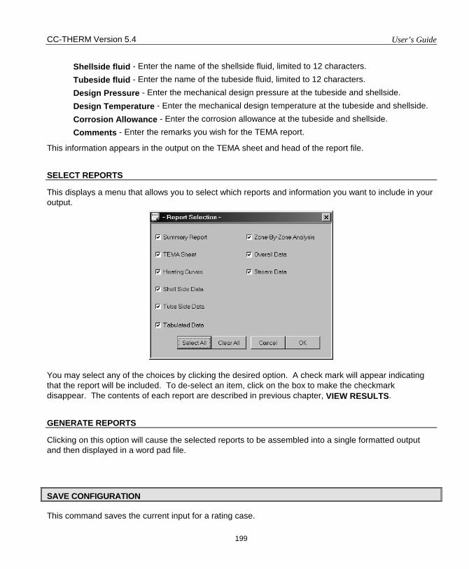
CC-THERM Version 5.4 User’s Guide
199
Shellside fluid - Enter the name of the shellside fluid, limited to 12 characters. Tubeside fluid - Enter the name of the tubeside fluid, limited to 12 characters. Design Pressure - Enter the mechanical design pressure at the tubeside and shellside. Design Temperature - Enter the mechanical design temperature at the tubeside and shellside. Corrosion Allowance - Enter the corrosion allowance at the tubeside and shellside. Comments - Enter the remarks you wish for the TEMA report.
This information appears in the output on the TEMA sheet and head of the report file.
SELECT REPORTS
This displays a menu that allows you to select which reports and information you want to include in your output. You may select any of the choices by clicking the desired option. A check mark will appear indicating that the report will be included. To de-select an item, click on the box to make the checkmark disappear. The contents of each report are described in previous chapter, VIEW RESULTS.
GENERATE REPORTS
Clicking on this option will cause the selected reports to be assembled into a single formatted output and then displayed in a word pad file.
SAVE CONFIGURATION
This command saves the current input for a rating case.
User’s Guide CC-THERM Version 5.4
200
RE-ENTER STREAM INFORMATION
This command allows user to get stream data from CHEMCAD flow sheet for the four streams going in and out of the current heat exchanger. This command is very useful when stream data of the unit to be sized is changed. Utility side stream will be recalculated for one side heat exchanger and heat curve will be regenerated using this feature.
RE-INITIALIZE EXCHANGER
This command deletes all of the input and output data for the current exchanger and starts a new analysis. This command is useful when one wants to switch to other types of exchanger, i.e., from double pipe heat exchanger to shell and tube heat exchanger.
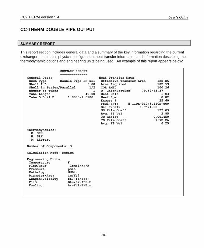
CC-THERM Version 5.4 User’s Guide
201
CC-THERM DOUBLE PIPE OUTPUT
SUMMARY REPORT
This report section includes general data and a summary of the key information regarding the current exchanger. It contains physical configuration, heat transfer information and information describing the thermodynamic options and engineering units being used. An example of this report appears below:
SUMMARY REPORT -------------- General Data: Heat Transfer Data: Exch Type Double Pipe BF_x51 Effective Transfer Area 128.85 Shell I.D. 6.00 Area Required 102.59 Shell in Series/Parallel 1/2 COR LMTD 100.26 Number of Tubes 1 U (Calc/Service) 79.59/63.37 Tube Length 40.00 Heat Calc 1.03 Tube O.D./I.D. 1.9000/1.6100 Heat Spec 0.82 Excess % 25.60 Foul(S/T) 5.110E-010/5.110E-009 Del P(S/T) 1.95/1.28 SS Film Coeff 122.03 Avg. SS Vel 2.85 TW Resist 0.001459 TS Film Coeff 1692.26 Avg. TS Vel 6.25 Thermodynamics: K: SRK H: SRK D: Library Number of Components: 3 Calculation Mode: Design Engineering Units: Temperature F Flow/Hour (lbmol/h)/h Pressure psia Enthalpy MMBtu Diameter/Area in/ft2 Length/Velocity ft/(ft/sec) Film Btu/hr-ft2-F Fouling hr-ft2-F/Btu
User’s Guide CC-THERM 5.4
202
TEMA SHEET
The TEMA Sheet is reproduced from the TEMA book and is filled in for use as an equipment spec sheet. An example is given on the next page. Most of the items on the TEMA Sheet are self-explanatory. Only a few of them will be explained here as these few may not be intuitively obvious.
Type User or BF_nnn. User type is user specified double pipe heat exchanger. BF_nnn type is Brown Fintube company’s standard where nnn is the heat exchanger section type number. See Brown Fintube company’s sales brushes.
Surf/unit (G/E) The total surface area per unit. G means GROSS or overall area without discounting any part of the tube length which may be imbedded in the tubesheet. E is the effective surface area after discounting any portion of the tube length embedded in the tubesheet.
Calc (coefficient) The same coefficient as U CALC stated below (see: Overall Data). See the below discussion of U CALC for more details. It is the overall heat transfer coefficient, taking into account the fouling factors on the shellside and the tubeside. When the exchanger is oversurfaced, the CALC coefficient always exceeds the SERVICE coefficient.
Service (coefficient) This is the coefficient calculated from service heat specification, effective transfer area, and corrected LMTD.
RHO-V2-inlet nozzle
The same as the quantity RV2 IN which is defined above. This is momentum term of the incoming shellside fluid at the inlet nozzle.
Designation Exchanger designation. Could be User or Brown Fintube designation code. See APPENDIX VIII for an example which details the definition of Brown Fintube designation code.
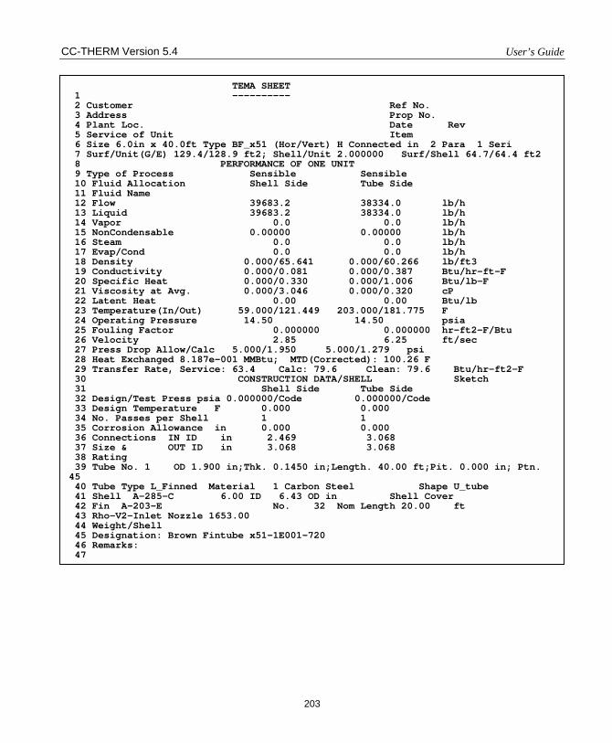
CC-THERM Version 5.4 User’s Guide
203
TEMA SHEET 1 ---------- 2 Customer Ref No. 3 Address Prop No. 4 Plant Loc. Date Rev 5 Service of Unit Item 6 Size 6.0in x 40.0ft Type BF_x51 (Hor/Vert) H Connected in 2 Para 1 Seri 7 Surf/Unit(G/E) 129.4/128.9 ft2; Shell/Unit 2.000000 Surf/Shell 64.7/64.4 ft2 8 PERFORMANCE OF ONE UNIT 9 Type of Process Sensible Sensible 10 Fluid Allocation Shell Side Tube Side 11 Fluid Name 12 Flow 39683.2 38334.0 lb/h 13 Liquid 39683.2 38334.0 lb/h 14 Vapor 0.0 0.0 lb/h 15 NonCondensable 0.00000 0.00000 lb/h 16 Steam 0.0 0.0 lb/h 17 Evap/Cond 0.0 0.0 lb/h 18 Density 0.000/65.641 0.000/60.266 lb/ft3 19 Conductivity 0.000/0.081 0.000/0.387 Btu/hr-ft-F 20 Specific Heat 0.000/0.330 0.000/1.006 Btu/lb-F 21 Viscosity at Avg. 0.000/3.046 0.000/0.320 cP 22 Latent Heat 0.00 0.00 Btu/lb 23 Temperature(In/Out) 59.000/121.449 203.000/181.775 F 24 Operating Pressure 14.50 14.50 psia 25 Fouling Factor 0.000000 0.000000 hr-ft2-F/Btu 26 Velocity 2.85 6.25 ft/sec 27 Press Drop Allow/Calc 5.000/1.950 5.000/1.279 psi 28 Heat Exchanged 8.187e-001 MMBtu; MTD(Corrected): 100.26 F 29 Transfer Rate, Service: 63.4 Calc: 79.6 Clean: 79.6 Btu/hr-ft2-F 30 CONSTRUCTION DATA/SHELL Sketch 31 Shell Side Tube Side 32 Design/Test Press psia 0.000000/Code 0.000000/Code 33 Design Temperature F 0.000 0.000 34 No. Passes per Shell 1 1 35 Corrosion Allowance in 0.000 0.000 36 Connections IN ID in 2.469 3.068 37 Size & OUT ID in 3.068 3.068 38 Rating 39 Tube No. 1 OD 1.900 in;Thk. 0.1450 in;Length. 40.00 ft;Pit. 0.000 in; Ptn. 45 40 Tube Type L_Finned Material 1 Carbon Steel Shape U_tube 41 Shell A-285-C 6.00 ID 6.43 OD in Shell Cover 42 Fin A-203-E No. 32 Nom Length 20.00 ft 43 Rho-V2-Inlet Nozzle 1653.00 44 Weight/Shell 45 Designation: Brown Fintube x51-1E001-720 46 Remarks: 47
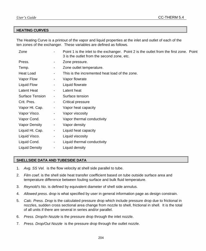
User’s Guide CC-THERM 5.4
204
HEATING CURVES The Heating Curve is a printout of the vapor and liquid properties at the inlet and outlet of each of the ten zones of the exchanger. These variables are defined as follows.
Zone - Point 1 is the inlet to the exchanger. Point 2 is the outlet from the first zone. Point 3 is the outlet from the second zone, etc.
Press. - Zone pressure. Temp. - Zone outlet temperature. Heat Load - This is the incremented heat load of the zone. Vapor Flow - Vapor flowrate Liquid Flow - Liquid flowrate Latent Heat - Latent heat Surface Tension - Surface tension Crit. Pres. - Critical pressure Vapor Ht. Cap. - Vapor heat capacity Vapor Visco. - Vapor viscosity Vapor Cond. - Vapor thermal conductivity Vapor Density - Vapor density Liquid Ht. Cap. - Liquid heat capacity Liquid Visco. - Liquid viscosity Liquid Cond. - Liquid thermal conductivity Liquid Density - Liquid density
SHELLSIDE DATA AND TUBESIDE DATA
1. Avg. SS Vel. is the flow velocity at shell side parallel to tube.
2. Film coef. is the shell side heat transfer coefficient based on tube outside surface area and temperature difference between fouling surface and bulk fluid temperature.
3. Reynold’s No. is defined by equivalent diameter of shell side annulus.
4. Allowed press. drop is what specified by user in general information page as design constrain.
5. Calc. Press. Drop is the calculated pressure drop which include pressure drop due to frictional in nozzles, sudden cross sectional area change from nozzle to shell, frictional in shell. It is the total of all units if there are several in series and/or parallel.
6. Press. Drop/In Nozzle is the pressure drop through the inlet nozzle.
7. Press. Drop/Out Nozzle is the pressure drop through the outlet nozzle.
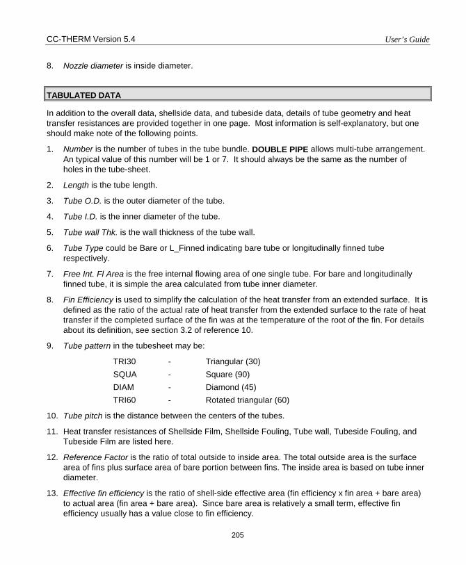
CC-THERM Version 5.4 User’s Guide
205
8. Nozzle diameter is inside diameter.
TABULATED DATA
In addition to the overall data, shellside data, and tubeside data, details of tube geometry and heat transfer resistances are provided together in one page. Most information is self-explanatory, but one should make note of the following points.
1. Number is the number of tubes in the tube bundle. DOUBLE PIPE allows multi-tube arrangement. An typical value of this number will be 1 or 7. It should always be the same as the number of holes in the tube-sheet.
2. Length is the tube length.
3. Tube O.D. is the outer diameter of the tube.
4. Tube I.D. is the inner diameter of the tube.
5. Tube wall Thk. is the wall thickness of the tube wall.
6. Tube Type could be Bare or L_Finned indicating bare tube or longitudinally finned tube respectively.
7. Free Int. Fl Area is the free internal flowing area of one single tube. For bare and longitudinally finned tube, it is simple the area calculated from tube inner diameter.
8. Fin Efficiency is used to simplify the calculation of the heat transfer from an extended surface. It is defined as the ratio of the actual rate of heat transfer from the extended surface to the rate of heat transfer if the completed surface of the fin was at the temperature of the root of the fin. For details about its definition, see section 3.2 of reference 10.
9. Tube pattern in the tubesheet may be:
TRI30 - Triangular (30) SQUA - Square (90) DIAM - Diamond (45) TRI60 - Rotated triangular (60)
10. Tube pitch is the distance between the centers of the tubes.
11. Heat transfer resistances of Shellside Film, Shellside Fouling, Tube wall, Tubeside Fouling, and Tubeside Film are listed here.
12. Reference Factor is the ratio of total outside to inside area. The total outside area is the surface area of fins plus surface area of bare portion between fins. The inside area is based on tube inner diameter.
13. Effective fin efficiency is the ratio of shell-side effective area (fin efficiency x fin area + bare area) to actual area (fin area + bare area). Since bare area is relatively a small term, effective fin efficiency usually has a value close to fin efficiency.
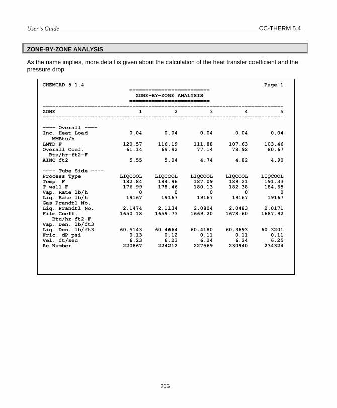
User’s Guide CC-THERM 5.4
206
ZONE-BY-ZONE ANALYSIS
As the name implies, more detail is given about the calculation of the heat transfer coefficient and the pressure drop.
CHEMCAD 5.1.4 Page 1 ========================= ZONE-BY-ZONE ANALYSIS ========================= --------------------------------------------------------------------------- ZONE 1 2 3 4 5 --------------------------------------------------------------------------- ---- Overall ---- Inc. Heat Load 0.04 0.04 0.04 0.04 0.04 MMBtu/h LMTD F 120.57 116.19 111.88 107.63 103.46 Overall Coef. 61.14 69.92 77.14 78.92 80.67 Btu/hr-ft2-F AINC ft2 5.55 5.04 4.74 4.82 4.90 ---- Tube Side ---- Process Type LIQCOOL LIQCOOL LIQCOOL LIQCOOL LIQCOOL Temp. F 182.84 184.96 187.09 189.21 191.33 T wall F 176.99 178.46 180.13 182.38 184.65 Vap. Rate lb/h 0 0 0 0 0 Liq. Rate lb/h 19167 19167 19167 19167 19167 Gas Prandtl No. Liq. Prandtl No. 2.1474 2.1134 2.0804 2.0483 2.0171 Film Coeff. 1650.18 1659.73 1669.20 1678.60 1687.92 Btu/hr-ft2-F Vap. Den. lb/ft3 Liq. Den. lb/ft3 60.5143 60.4664 60.4180 60.3693 60.3201 Fric. dP psi 0.13 0.12 0.11 0.11 0.11 Vel. ft/sec 6.23 6.23 6.24 6.24 6.25 Re Number 220867 224212 227569 230940 234324
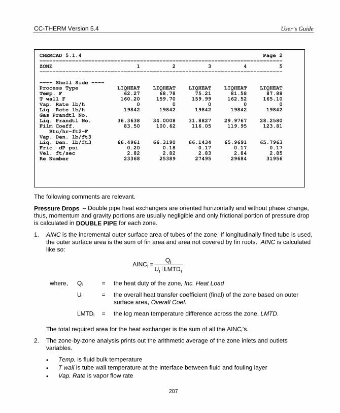
CC-THERM Version 5.4 User’s Guide
207
The following comments are relevant.
Pressure Drops – Double pipe heat exchangers are oriented horizontally and without phase change, thus, momentum and gravity portions are usually negligible and only frictional portion of pressure drop is calculated in DOUBLE PIPE for each zone.
1. AINC is the incremental outer surface area of tubes of the zone. If longitudinally fined tube is used, the outer surface area is the sum of fin area and area not covered by fin roots. AINC is calculated like so:
iii
i LMTDUQ
AINC⋅
=
where, Qi = the heat duty of the zone, Inc. Heat Load
Ui = the overall heat transfer coefficient (final) of the zone based on outer surface area, Overall Coef.
LMTDi = the log mean temperature difference across the zone, LMTD.
The total required area for the heat exchanger is the sum of all the AINCi’s.
2. The zone-by-zone analysis prints out the arithmetic average of the zone inlets and outlets variables.
• Temp. is fluid bulk temperature • T wall is tube wall temperature at the interface between fluid and fouling layer • Vap. Rate is vapor flow rate
CHEMCAD 5.1.4 Page 2 --------------------------------------------------------------------------- ZONE 1 2 3 4 5 --------------------------------------------------------------------------- ---- Shell Side ---- Process Type LIQHEAT LIQHEAT LIQHEAT LIQHEAT LIQHEAT Temp. F 62.27 68.78 75.21 81.58 87.88 T wall F 160.20 159.70 159.99 162.52 165.10 Vap. Rate lb/h 0 0 0 0 0 Liq. Rate lb/h 19842 19842 19842 19842 19842 Gas Prandtl No. Liq. Prandtl No. 36.3638 34.0008 31.8827 29.9767 28.2580 Film Coeff. 83.50 100.62 116.05 119.95 123.81 Btu/hr-ft2-F Vap. Den. lb/ft3 Liq. Den. lb/ft3 66.4961 66.3190 66.1434 65.9691 65.7963 Fric. dP psi 0.20 0.18 0.17 0.17 0.17 Vel. ft/sec 2.82 2.82 2.83 2.84 2.85 Re Number 23368 25389 27495 29684 31956
User’s Guide CC-THERM 5.4
208
• Liq. Rate is liquid flow rate • Vap. Den. is vapor phase density • Liq. Den. is liquid phase density.
3. The following numbers are calculated from the average properties of the zone:
• Gas Prandtl No. is vapor phase Prandtl ‘s number • Liq. Prandtl No. is liquid phase Prandtl’s number • Film Coeff. is heat transfer coefficient of fluid film next to fouling layer • Fric. dP is pressure drop due to friactional pressure loss. • Vel. is fluid velocity • Re Number is Reynolds’s number of fluid. If the fluid is in the shell annulus, equivalent
diameter is used in calculating this number.
OVERALL DATA
1. Area Total is the total installed area of the heat exchangers. It is the total outer surface area of a single tube times the total number of tubes. For longitudinally finned tubes, the area is the total area of the fins plus area not covered by fin roots. For multi-units combination, the area is the total of all units.
2. Area Required is the area total needed to transfer the specified heat duty of the exchanger. This value is determined by summing the incremental areas, AINCi’s of all the zones.
3. Area Effective of the exchanger excludes that portion of the tube length, which is covered by the tubesheet.
4. Area Per Shell is the Area Total of one shell.
5. The % excess is the excess area for the present calculation. Excess area is obtained by comparing relatively Area Total with Area Required. This value is always expressed as a percent. A negative value indicates that the exchanger is undersurfaced. When making a design run, the program usually terminates the calculation when the excess area is greater than 0.
6. U Calc is the calculated overall heat transfer coefficient for the whole exchanger based on outer surface area of tube. Since an overall heat transfer coefficient, Ui, is calculated for each zone, the definition of U Calc is somewhat a matter of convention. CC-THERM defines U Calc as:
)WLMTD()Area(Q
Ureq.
TotalCalc =
CC-THERM Version 5.4 User’s Guide
209
where, QTotal = the heat duty of the exchanger
Areareq = the required area which is the sum of the incremental areas for all zones; this is outer surface area of tube; for longitudinally finned tubes, this area is the total area of the fins plus area not covered by fin roots .
WLMTD = the log mean temperature difference which is calculated like so:
∑=
ii
Total
LMTDQ
QWLMTD
where, QTotal = the heat duty of the exchanger
Qi = the incremental heat duty of zone i.
LMTDi = the log mean temperature difference for zone i.
7. U Service is the exchanger service heat transfer coefficient. This quantity is not a function of the calculated heat transfer coefficients. It depends on the heat load, the temperature difference, and the effective surface area:
WLMTDAreaQU Total
Service ⋅=
where, QTotal = the heat duty of the exchanger
Area = the total effective area of the exchanger.
WLMTD = the weighted log mean temperature difference.
8. Heat Duty is the heat load for given inlet and outlet streams.
9. Weight LMTD is the WLMTD – weighted logarithmic mean temperature difference.
STREAM OUTPUT
The stream output section allows you to include stream composition data in your printed output. It is analogous to CHEMCAD, except only those streams that are included in the exchanger will appear in the report.
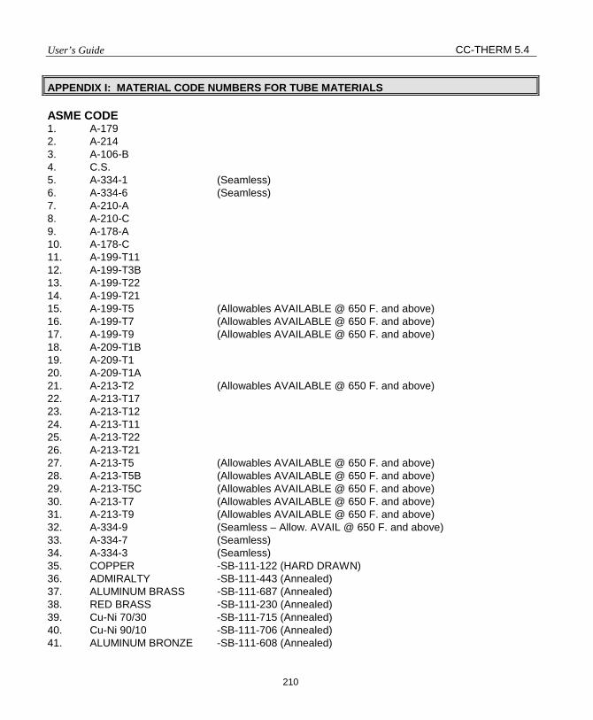
User’s Guide CC-THERM 5.4
210
APPENDIX I: MATERIAL CODE NUMBERS FOR TUBE MATERIALS
ASME CODE 1. A-179 2. A-214 3. A-106-B 4. C.S. 5. A-334-1 (Seamless) 6. A-334-6 (Seamless) 7. A-210-A 8. A-210-C 9. A-178-A 10. A-178-C 11. A-199-T11 12. A-199-T3B 13. A-199-T22 14. A-199-T21 15. A-199-T5 (Allowables AVAILABLE @ 650 F. and above) 16. A-199-T7 (Allowables AVAILABLE @ 650 F. and above) 17. A-199-T9 (Allowables AVAILABLE @ 650 F. and above) 18. A-209-T1B 19. A-209-T1 20. A-209-T1A 21. A-213-T2 (Allowables AVAILABLE @ 650 F. and above) 22. A-213-T17 23. A-213-T12 24. A-213-T11 25. A-213-T22 26. A-213-T21 27. A-213-T5 (Allowables AVAILABLE @ 650 F. and above) 28. A-213-T5B (Allowables AVAILABLE @ 650 F. and above) 29. A-213-T5C (Allowables AVAILABLE @ 650 F. and above) 30. A-213-T7 (Allowables AVAILABLE @ 650 F. and above) 31. A-213-T9 (Allowables AVAILABLE @ 650 F. and above) 32. A-334-9 (Seamless – Allow. AVAIL @ 650 F. and above) 33. A-334-7 (Seamless) 34. A-334-3 (Seamless) 35. COPPER -SB-111-122 (HARD DRAWN) 36. ADMIRALTY -SB-111-443 (Annealed) 37. ALUMINUM BRASS -SB-111-687 (Annealed) 38. RED BRASS -SB-111-230 (Annealed) 39. Cu-Ni 70/30 -SB-111-715 (Annealed) 40. Cu-Ni 90/10 -SB-111-706 (Annealed) 41. ALUMINUM BRONZE -SB-111-608 (Annealed)
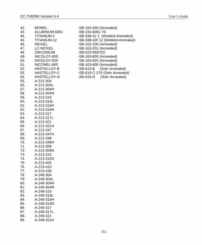
CC-THERM Version 5.4 User’s Guide
211
42. MONEL -SB-163-400 (Annealed) 43. ALUMINUM-6061 -SB-234-6061-T6 44. TITANIUM-2 -SB-338-Gr 2 (Welded-Annealed) 45. TITANIUM-12 -SB-338-GR 12 (Welded-Annealed) 46. NICKEL -SB-163-200 (Annealed) 47. LC-NICKEL -SB-163-201 (Annealed) 48. ZIRCONIUM -SB-523-R60702 49. INCOLOY-800 -SB-163-800 (Annealed) 50. INCOLOY-825 -SB-163-825 (Annealed) 51. INCONEL-600 -SB-163-600 (Annealed) 52. HASTELLOY-B -SB-619-B (Soln Annealed) 53. HASTELLOY-C -SB-619-C-276 (Soln Annealed) 54. HASTELLOY-G -SB-619-G (Soln Annealed) 55. A-213-304 56. A-213-304L 57. A-213-304H 58. A-213-304N 59. A-213-316 60. A-213-316L 61. A-213-316H 62. A-213-316N 63. A-213-317 64. A-213-317L 65. A-213-321 66. A-213-321H 67. A-213-347 68. A-213-347H 69. A-213-348 70. A-213-348H 71. A-213-309 72. A-213-309S 73. A-213-310 74. A-213-310S 75. A-213-405 76. A-213-410 77. A-213-430 78. A-249-304 79. A-249-304L 80. A-249-304H 81. A-249-304N 82. A-249-316 83. A-249-316L 84. A-249-316H 85. A-249-316N 86. A-249-317 87. A-249-317L 88. A-249-321 89. A-249-321H
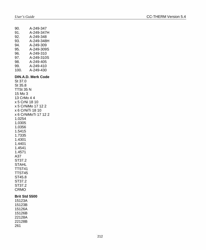
User’s Guide CC-THERM Version 5.4
212
90. A-249-347 91. A-249-347H 92. A-249-348 93. A-249-348H 94. A-249-309 95. A-249-309S 96. A-249-310 97. A-249-310S 98. A-249-405 99. A-249-410 100. A-249-430
DIN.A.D. Merk Code St 37.0 St 35.8 TTSt 35 N 15 Mo 3 13 CrMo 4 4 x 5 CrNi 18 10 x 5 CrNiMo 17 12 2 x 6 CrNiTi 18 10 x 6 CrNiMoTi 17 12 2 1.0254 1.0305 1.0356 1.5415 1.7335 1.4301 1.4401 1.4541 1.4571 A37 ST37.2 STAHL TTST41 TTST45 ST45.8 ST37.2 ST37.2 CRMO
Brit Std 5500 15123A 15123B 15126A 15126B 22128A 22128B 261

CC-THERM Version 5.4 User’s Guide
213
271 304S15 316S16
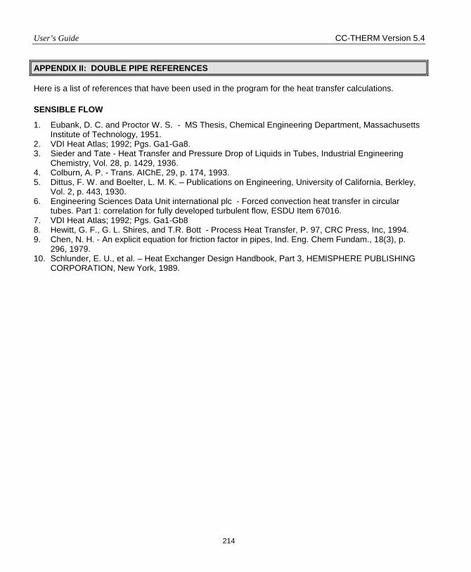
User’s Guide CC-THERM Version 5.4
214
APPENDIX II: DOUBLE PIPE REFERENCES
Here is a list of references that have been used in the program for the heat transfer calculations.
SENSIBLE FLOW
1. Eubank, D. C. and Proctor W. S. - MS Thesis, Chemical Engineering Department, Massachusetts Institute of Technology, 1951.
2. VDI Heat Atlas; 1992; Pgs. Ga1-Ga8. 3. Sieder and Tate - Heat Transfer and Pressure Drop of Liquids in Tubes, Industrial Engineering
Chemistry, Vol. 28, p. 1429, 1936. 4. Colburn, A. P. - Trans. AIChE, 29, p. 174, 1993. 5. Dittus, F. W. and Boelter, L. M. K. – Publications on Engineering, University of California, Berkley,
Vol. 2, p. 443, 1930. 6. Engineering Sciences Data Unit international plc - Forced convection heat transfer in circular
tubes. Part 1: correlation for fully developed turbulent flow, ESDU Item 67016. 7. VDI Heat Atlas; 1992; Pgs. Ga1-Gb8 8. Hewitt, G. F., G. L. Shires, and T.R. Bott - Process Heat Transfer, P. 97, CRC Press, Inc, 1994. 9. Chen, N. H. - An explicit equation for friction factor in pipes, Ind. Eng. Chem Fundam., 18(3), p.
296, 1979. 10. Schlunder, E. U., et al. – Heat Exchanger Design Handbook, Part 3, HEMISPHERE PUBLISHING
CORPORATION, New York, 1989.