Embed Size (px)
Citation preview

Rapid Design Systems for Aerospace Structures Page I
_ccReport on Grant Nt_-1-261
Research and Development of Rapid Design Systems forAerospace Structure
. L
6" _ •
A report Submitted to the National Aeronautics and Space Administration
By Harry G. Schaeffer
February l, 1999
Mechanical Engineering Department
University of LouisvilleLouisville, KY 40202
https://ntrs.nasa.gov/search.jsp?R=19990087362 2018-07-14T00:18:23+00:00Z
Rapid Design Systems for Aerospace Structures Page 2
SummaryThis report describes the results of research activities associated with the development of rapid designsystems for aerospace structures in support of the Intelligent Synthesis Environment (ISE). The specific
subsystems investigated were the interface between model assembly and analysis; and, the highperformance NASA GPS equation solver software system in the Windows NT environment on low cost
high-performance PCs.
Requirements for Analysis Subsystem
The requirements for the analysis subsystem of the ISE were evaluated. It was found that the analysissubsystem is not integrated into the Model Assembler. This phase of the research identified a need for
better integration to provide rapid analysis response to the ISE system. The changes identified include:
1. Developing a part-oriented analysis subsystem2. Developing a multi-instance analysis system that would generate data for parts as they are selected by
the Model Assembler
Performance of Equation Solver on PCsThe NASA GPS solver was installed on Windows NT for operation on PCs. The results of a
comprehensive performance study showed that:1. PCs gave remarkable performance for large problems2. PCs should be configured with maximum memory to enhance performance.
3. There is a significant difference between compilers. The lntel Fortran 2.0 compiler gave consistentlybetter performance compared with other market leaders. However, other factors influence the choice
of compilers other than efficiency of the source code.
Purpose of ResearchThe purpose of this grant was to evaluate the requirements for the rapid analysis subsystem and associated
technology to support the Intelligent Synthesis Environment. The activities associated with this grant wereto focus on the following technology areas:
1. Interface technology (IT)2. High performance equation solvers, and3. Methodology for interfacing the analysis subsystem with the ISE environment
IntroductionThe NASA has identified the Intelligent Synthesis Environment (ISE) as enabling technology that supportsfulfillment of its mission to design new space and aeronautical systems in the next decade. The
Computational Structures Branch at the NASA Langley Research Center had, at the time of the researchdescribed in this report, begun to develop a prototype software system called NEXTGRADE forassembling Design Analysis Objects (DOA) to support the analysis subsystem of the ISE. This prototypewas used to evaluate the potential of using the Microsoft Windows/NT operating system to support the
network requirements for the structural design/analysis subsystem for the ISE program and to serve as atest bed for a structural assembler.
The design/analysis system contains an object-oriented database of part design objects. Each part is a
distinct object containing the part geometry, interface points, lines and surfaces and a finite element model.The NEXTGRADE system displays parts in the design database iconically. The parts can then be moved
into the active viewing window for display and manipulation. Once in the display window the object'sfeatures such as interface points can be displayed. Two or more parts which comprise a design assemblycan then be commanded to attach at the interface points in a grouping operation. The result of the
operation is visually confirmed by having the objects snap together at the interface; and within the

RapidDesignSystemsfor Aerospace Structures Page 3
NEXTGRADE system an interface data object is generated that includes the parameters associated with the
interface in a form that can be interpreted by the target analysis subsystem.
In this paradigm for assembling analysis models, the interface definition is a key enabling technology. The
technology used at present in the COMET-AR subsystem is that developed by Ransom (JR) et al [1-5] thatallows line-to-line, line-to-surface and surface-to-surface attachment. The new interface technology
augments the established point-to-point procedure for attaching separate components using an
implementation technology termed Multi Point Constraints (MPC). The formulation for the JR interfaceelement requires the construction of a spline line or surface between the two parts to be joined.
The implementation of the formulation results in system matrices that are non-positive definite that cannotbe solved using standard skyline solvers. To support the solution of large non-positive definite matrices the
NASA supported research that lead to the development of very efficient sparse solvers called GPS that
have been implemented in the COMET-AR system.
Interface Requirements to the Analysis SubsystemThe approach taken in the prototype development of the NEXTGRADE Model Assembler (MA) is toinclude the finite element model of the part in the data object. This is restrictive for several reasons:
1. In collaborative design activities involving participants from several organizations the f'mite element
model might not be available for competitive reasons.2. The response of the part might be defined in terms of flexibility coefficients or component modes.
3. The paradigm of a separate fixed element analysis is probably obsolete, especially with thedevelopment of efficient automated tools for model creation and the potential requirement forautomated mesh refinement to obtain results accurate to within an established error.
These observations result in the conclusion that the production version of the MA must include a more
general database that allows for several forms of the model def'mition, including one associated with the
geometric description of the part.
In the current MA prototype, the input file for the target analysis subsystem, which is limited to COMET-AR at the present time, is generated from the part finite element models in the linked part list and the
interface definitions generated as a part of the assembly process. The result is a model of the assembly
rather than a model of separate parts coupled by interface elements.
An aitemative paradigm, which is advocated for the production version of the design/analysis subsystem of
the ISE, is to support a high degree of associativity between the MA and the analysis subsystem to improvethe response of the combined subsystem to design requests for analysis. Since multiple computers areavailable on the network all available computing resource can be utilized by part-oriented analysis. The
concept, which is described in more detail in a later section, is to directly connect analysis support to MAoperations. When the designer selects an icon and activates it by moving it into the view window, ananalysis sub task can be spawned and assigned to a processor. While the designer is performing further
actions on the MA a major part of the operations associated with the analysis can be performed including ata minimum the generation and assembly of the system matrices for the part.
The incorporation of macro parallelism utilizing multiple processors will require modifications to the MAand major modifications to the current architecture of the analysis subsystem. The specifications for new
system architecture for NASTRAN are described in a later section.
Alternative Strategy for Interface TechnologyThe interface technology developed by JR has been shown to decrease the errors in stress at the interface
several orders of magnitude. However, in the general case when lines of nodes on mating parts do notalign, the strategy is to remesh the surface elements to establish congruency of lines containing nodes.Remeshing means the current finite element model in the part object is not correct; and, the requirement for

RapidDesignSystemsfor Aerospace Structures Page 4
remeshing also means that macro parallelism cannot be implemented. In addition, the implementation
results in non-positive definite matrices.
The solution strategy for non-positive definite matrices results in having to operate on a dense matrix oforder of the number of the LaGrange multipliers defined in the JR method. The interface might result in a
large number of LaGrange multipliers and therefor a large dense matrix to invert which will be the case insurface-to-surface interfaces. Alternative strategies for generating constraint equations associated with the
general interface problem should be pursued. Alternative strategies should:1. Create MPC type relations resulting in a reduction rather than an increase in the size of the assembly
matrix and in a positive definite matrix.2. Allow parts to be processed independently through the generation and assembly phases.
Requirements for Part-Oriented Analysis SubsystemThe requirements for a part-aware Intelligent Analysis Environment (IAE) subsystem system are:1. A part is an independent design object and can be processed independently of other parts.
2. A part may be def'med in terms of system matrices, component modes, a finite element model or a
geometric model3. A part object is polymorphic and can be rotated, translated and combined arbitrarily with other
appropriate part objects using interface definitions.4. The analysis program should be object-oriented and allow multiple instances part analyses on multiple
processors either on a single computer or over a network of computers5. The analysis subsystem should be object-connected to the MA. The MA should send part models and
interface definitions to the IAE; and, the IAE should send part-oriented results to the MA
6. The IAS should be support industry standard data structures associated with a single finite elementmodel.
7. The implementation software platform should support a problem-oriented language, such as DMAP toallow extension of part-oriented analysis to normal modes and dynamic analysis
Intelligent Analysis Environment (IAE)The discussion of the proposed IAS is based on using NASTRAN as an implementation platform. It waschosen for several reasons, not the least of which is that the author is familiar with the NASTRANarchitecture. In addition, NASTRAN is modular and incorporates a procedural language called DMAP.
The IAS will:
• Provide context switching for part-oriented operations.
• Support new model definition data structures
• Allow part loop control in the DMAP program
• Support parametric part objects
• Support part transformations
• Adaptive meshing
• Stress smoothing and error estimation
• Adaptive mesh refinement and interface element generation
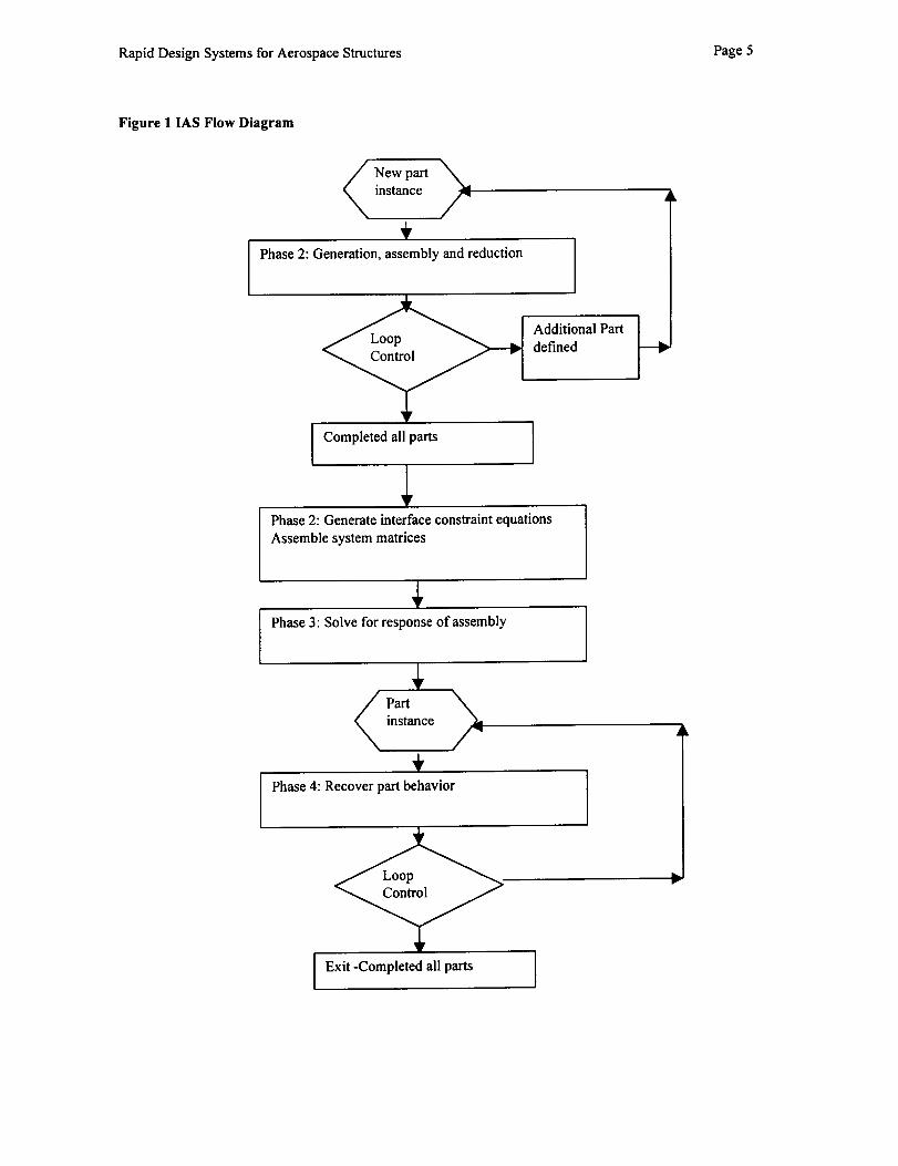
The flow diagram for the proposed IAS is shown by Figure 1:
RapidDesignSystemsforAerospaceStructures Page5
Figure I IAS Flow Diagram
New partinstance
Phase 2: Generation, assembly and reduction
Completed all parts
Additional Part
defined
Phase 2: Generate interface constraint equations
Assemble system matrices
Phase 3: Solve for response of assembly
\instance
/"
Phase 4: Recover part behavior
@>Exit -Completed all parts

RapidDesignSystemsforAerospaceStructures Page6
Input Data File
The input data file for the IAS will look like a standard NASTRAN data file.• EXECUTIVE Control
No changes from standard NASTRAN• CASE Control
Little or no changes from standard NASTRAN• BULK Data
• Accepts current data file for a single part analysis• New PART statement required to delimit part objects
Bulk Data Section
|fthe Bulk data contains multiple part instances each model must be encapsulated and contain a complete
part model. The part input supports standard finite element modeling data statements and new data
statements that associate the part with a geometric model.
Specification for the IAS
The objectives of design/Analysis objects is to:
1. Pass the physics model to an analysis program2. Receive and display results and convergence data
Discussion
The part database objects assembled by NEXTRADE include a finite element model data object for thepart. The finite element model is created independently using a finite element modeling program such asMSC/PATRAN of FEMAP. After assembling the part objects NEXTGRADE merges the part finite
element objects to create a f'mite element model for the entire assembly that includes the interface
definitions generated in the MA assembly operation.
NEXTGRADE is designed to use existing data structures and modeling capability associated with standardfinite element modeling and analysis programs. When preparing the input file for a target analysis
subsystem NEXTGRADE is constrained by: the following factors:
1. All grid numbers must be unique2. All element numbers must be unique3. Few if any, modeling programs attempt to support component modeling based on multiple components
such as superelements in MSC/NASTRAN.4. Display requirements may differ from analysis requirements. In a three-dimensional stress model the
physics is defined throughout the continuum. However, the maximum stress occurs on the boundary
5. Modelers do not support interface technology such as that developed at NASA Langely by Ransom etal.
New Paradigm for Design Systems
Combining subsystems and components creates the assembled analysis model. A component, or designobject, is the basic building block that can be combined to create a virtual system model. Design objectsallow the design team to synthesize complex systems by combining design objects using a virtual design
system such as NEXTGRADE.
The data objects must incorporate data and operators which:
1. Define the geometry of the object2. Define the physical properties of the object3. Define interface geometry including points, edges and surfaces on which loads and constraints can be
applied and which can be connected to other deign entities.4. Define external loads and constraints with reference to interface geometry as a function of time or
other parameters.
RapidDesignSystemsforAerospaceStructures Page7
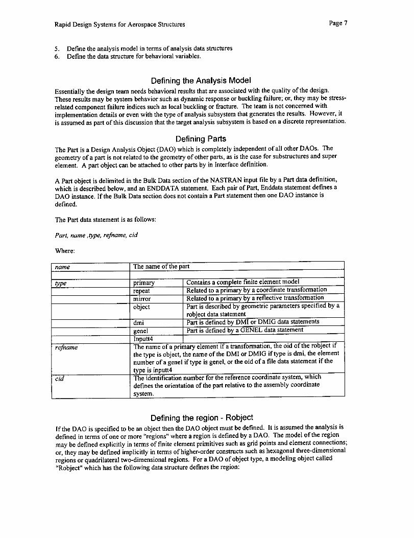
5. Definetheanalysismodelintermsofanalysisdatastructures6. Definethedatastructureforbehavioralvariables.
Defining the Analysis Model
Essentially the design team needs behavioral results that are associated with the quality of the design.
These results may be system behavior such as dynamic response or buckling failure; or, they may be stress-related component failure indices such as local buckling or fracture. The team is not concerned with
implementation details or even with the type of analysis subsystem that generates the results. However, itis assumed as part of this discussion that the target analysis subsystem is based on a discrete representation.
Defining Parts
The Part is a Design Analysis Object (DAO) which is completely independent of all other DAOs. Thegeometry of a part is not related to the geometry of other parts, as is the case for substructures and super
element. A part object can be attached to other parts by in Interface definition.
A Part object is delimited in the Bulk Data section of the NASTRAN input file by a Part data def'mition,which is described below, and an ENDDATA statement. Each pair of Part, Enddata statement defines aDAO instance. If the Bulk Data section does not contain a Part statement then one DAO instance is
defined.
The Part data statement is as follows:
Part, name ,type, refname, cid
Where:
name The name of the part
type primary Contains a complete finite element modelrepeat Related to a primary by a coordinate transformation
mirror Related to a primary by a reflective transformation
object Part is described by geometric parameters specified by a
robject data statementdmi Part is defined by DMI or DMIG data statements
genel Part is defined by a GENEL data statement
refname
cM
Inputt4The name of a primary element if a transformation, the oid of the robject ifthe type is object, the name of the DMI or DMIG if type is dmi, the element
number of a genel if type is genel, or the oid of a file data statement if the
type is inputt4The identification number for the reference coordinate system, which
defines the orientation of the part relative to the assembly coordinate
system.
Defining the region - Robject
If the DAO is specified to be an object then the DAO object must be defined. It is assumed the analysis isdefined in terms of one or more "regions" where a region is defined by a DAO. The model of the region
may be defined explicitly in terms of finite element primitives such as grid points and element connections;
or, they may be def'med implicitly in terms of higher-order constructs such as hexagonal three-dimensionalregions or quadrilateral two-dimensional regions. For a DAO of object type, a modeling object called
"Robject" which has the following data structure def'mes the region:
RapidDesignSystemsfor Aerospace Structures Page 8
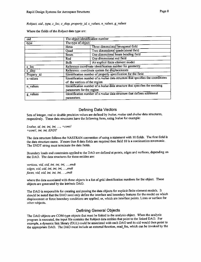
Robject, oid, type, c_loc, c_disp, property_id, x_values, n_values, g_values
Where the fields of the Robject data type are:
oid The object identification number
type The type of object:Hexa Three dimensional hexagonal field
Quad Two dimensional quadrilateral fieldBeam One dimensional beam bending fieldRod One dimensional rod field
Bulk An explicit finite element model
c loc Reference coordinate identification number for geometry
c_disp Reference: coordinate system for displacements
Propery_id Identification number of property specification for the fieldx-values Identification number of a rvalue data structure that specifies the coordinates
of the vertices of the regionn values Identification number ofa lvalue data structure that specifies the meshing
parameters for the region
g_values Identification number of a rvalue data structure that defines additional
parameters.
Defining Data Vectors
Sets of integer, real or double precision values are defined by lvalue, rvalue and dvalue data structures,respectively. These data structures have the following form, using lvalue for example:
Lvalue, id, int, int, int, .... +contl+contl, int, int, ENDT
The data structure follows the NASTRAN convention of using a statement with 10 fields. The first field is
the data structure name. If more than 8 data fields are required then field I 0 is a continuation mnemonic.
The ENDT string must terminate the data fields.
Boundary loads and constraints applied to the DAO are defined at points, edges and surfaces, depending onthe DAO. The data structures for these entities are:
vertices, vid, oid, int, int, int, .... endt
edges, vid, oid, int, int, int, .... endt
faces, vid, oid, int, int, int, .... endt
where the data associated with these objects is a list of grid identification numbers for the object. These
objects are generated by the intrinsic DAO.
The DAO is responsible for creating and passing the data objects for explicit finite element models. Itshould be noted that the DAO need only define the interface and boundary features for the model on which
displacement or force boundary conditions are applied; or, which are interface points. Lines or surface for
other robjects.
Defining General Objects
The DAO objects are COM-type objects that must be linked to the analysis object. When the analysis
program is executed, the input file contains the Robject data entities that point to the linked DAO. Forexample, a dynamic link library (DLL) could be associated with each DAO and its oid would then point to
the appropriate DAO. The DAO must include an external function, read_fea, which can be invoked by the

RapidDesignSystemsforAerospaceStructures Page9
analysis program to read the model described by the DAO. The input file will also include other runtime
data statements appropriate for the target analysis program.
Assuming NASTRAN is the target analysis subsystem, the object is encapsulated in the Bulk Data. Theuniqueness rules for Bulk Data thus only apply locally to the object. The enhanced NASTRAN systemassociates a complete run-time state with each DAO in addition to the run-time state for a traditional f'mite
element model, if any. Each instance of the run-time state is associated with a Part data statement.
Modifying NASTRAN to Support DAOEach instance of the run-time state creates an entry in a table maintained within the enhanced NASTRAN
system. NASTRAN thus becomes a state machine that allows multiple instances of any data block in aDMAP solution. The use of the instance table in essence provides a facility for subscripted data blocks.
The model incorporated in each DAO must be capable of:1. Generating the assembled system matrices2. Reducing the system matrices to the solution set.3. Def'ming interface features at which the DAO can be attached to other DAOs.
The enhanced analysis subsystem must support a traditional model as well as multiple DAOs. The DMAP
program will thus include a multi-instance loop for generating and reducing the models for each DAO tothe solution set. This is accomplished by:1. Modifying the input file processor to accept the new data structures2. Implementing the object instance table
3. Implementing new DMAP Executive commands that are associated with the instance loop4. Implementing a new module called ROBJ that generates the following data blocks for each DOA
instance:
The uset table
The equivalence table between internal and external grid point numbersThe reduced stiffness and load matrices
The scalar load table
The material tableetc.
5. Implementing the OBJMA module to:Read interface data objects from the inputGenerate interface matrices
assemble the analysis objects.6. Implementing the NASA GPS sparse matrix solver to solve the set of symmetric non positive definite
equations
7. Implementing the SDROBJ module to recover the requested behavioral variables for each DOA.
Interface Objects
In addition to the standard finite element modeling entities DOA must include a def'mition of itsinterface(s) to other DOAs. An interface specification must then be defined in the Bulk Data section foreach DOA interface. The following interface data statement def'mes the interface between two DOA:
Interface, sid, type, oid, featurel, oid, feature2
Where:
Sial The interface identification number
type The type of interface
PTP The interface element connects points on each DOA thatare aligned
FIELD The interface element is to be generated to connect thetwo fields
RapidDesignSystemsforAerospaceStructures Page 10
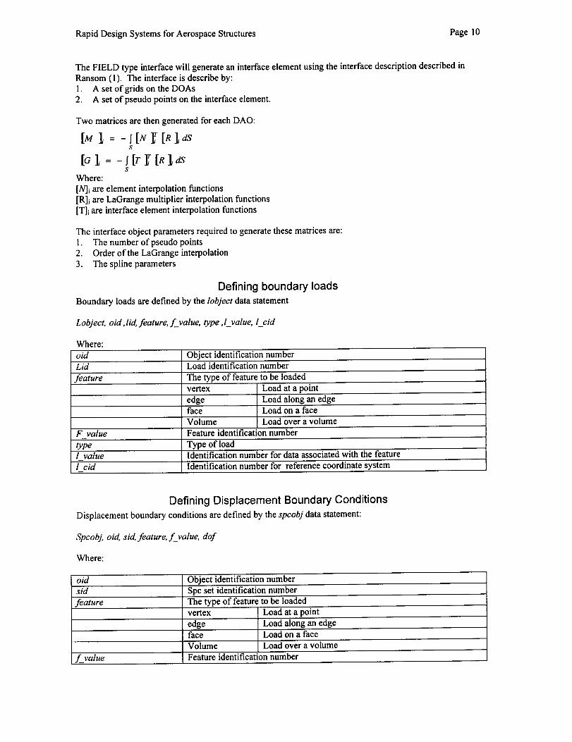
The FIELD type interface will generate an interface element using the interface description described in
Ransom (1). The interface is describe by:
1. A set of grids on the DOAs2. A set of pseudo points on the interface element.
Two matrices are then generated for each DAO:
[M I = -f[N 1_[R],dsS
[G1 = -lit r [RS
Where:
[N]i are element interpolation functions[R]i are LaGrange multiplier interpolation functions
[T]i are interface element interpolation functions
The interface object parameters required to generate these matrices are:1. The number of pseudo points2. Order of the LaGrange interpolation
3. The spline parameters
Defining boundary loads
Boundary loads are defined by the lobject data statement
Lobject, oid,lid, feature, f_value, type,l_value, l_cid
Where:
old Object identification numberLid Load identification number
feature The type of feature to be loadedvertex Load at a point
edge Load along an edgeface Load on a faceVolume Load over a volume
F value Feature identification number
type Type of load1 value Identification number for data associated with the feature
l cid Identification number for reference coordinate system
Defining Displacement Boundary Conditions
Displacement boundary conditions are defined by the spcobj data statement:
Spcobj, old, sid, feature, f_value, dof
where:
oid Object identification number
sid Spc set identification number
feature The type of feature to be loadedvertex Load at a point
edge Load along an edgeface Load on a face
Volume Load over a volume
f_value Feature identification number

Rapid Design Systems for Aerospace Structures Page 11
I dof [ Dof codes for displacement degrees of freedom to be constrained
Assembling Objects
The data blocks for each DAO are written to virtual memory. The data blocks include Kfr, Mr, and Gq.
The set of object interface points is specified by the features to be attached to the interface elements. The
interface forces associated with the interface elements is represented by the vector, 0t. The system of
equations in assembled form is:
Where {q} represents the union of all the displacementj%et for all DOA and {q,} is the union of all
interface element displacements.
[_K_ [0][0] ii_l t {q }]{q}_ = [ {f}'1{0}t{o}J
Evaluation of High-Performance Equation Solving SubsystemThe equation solving subsystem that supports the matrix topology associated with the interface technologyis called the NASA General-Purpose Sparse (GPS) solver.
Purpose of ResearchThe purpose of the research effort with the GPS solver was to evaluate the high performance GPS routines
for the Intelligent Synthesis Environment, which were only operational at Langley on Unix workstations,on PC systems. The thesis for this research is that the computer environment supporting ISE will include:
• Pentium II+ class CPU such as the Deschute and Merced chip sets.
• Large memory address space of 2 Gigabytes using Microsoft Windows 95, 98 and NT operating
systems.• Windows NT being the predominant network system used in the ISE
• Object-oriented encapsulated algorithms optimized for the fastest compiler.
Parameters of the Study
The test object is the established GPS program for efficiently solving large sets of linear equations. Theprogram was modified to run as either under Windows. Timing algorithms were implemented so that total
wall clock time, Tw, and cpu time, Tepu, were measured for both the factor and solution phases, In all casesonly one load vector was used.
Problem Sizes
The effect of problem size was studied by using four model sizes:
1. A 16,152 degree of freedom model2. A 54,870 degree of freedom model3. A 217,918 degree of freedom model
4. A 263,574 degree of freedom model
Computer HardwareThe effect of computer hardware parameters was studied by using two separate computers having different
CPU speeds and memory sizes. The systems used were:1. System 300 having a 300 MHz CPU and 256 Mbytes of main memory
2. System 333 having a 330 MHz CPU and 128Mbytes of main memory

RapidDesignSystemsforAerospaceStructures Page12
Compilers
The effect of compiler efficiently was studied by using three compilers:
1. Digital Visual Fortran 5.0 (DEC)2. Intel Fortran 2.0 (Intel)3. Microsott Power Station Fortran 4.0 (MS)
Operating System
The effect of operating system was studied by running the same problem using the same executable on a
dual boot system having both Windows NT and Windows 95. Windows 98 was not released at the time butsince it is a 16 bit operating system it will have approximately the same system performance as Window95.
TestingLimited performance comparisons made between Windows NT and Windows 95. All tests were performed
on computers, which were unloaded except for the operating system.
Results of Performance Study
Three tables summarize performance results:1. The influence of test parameters on the factorization time for the largest of the analysis test problems
2. The influence of test parameters on the solution time for the largest of the n analysis test problems.3. The influence of problem size for the when running on the system having the largest memory and code
generated by the most optimized compiler.
Factor time for Large Car Model
The following chart shows the factor time for the large car model.
Rapid Design Systems for Aerospace Structures Page 13
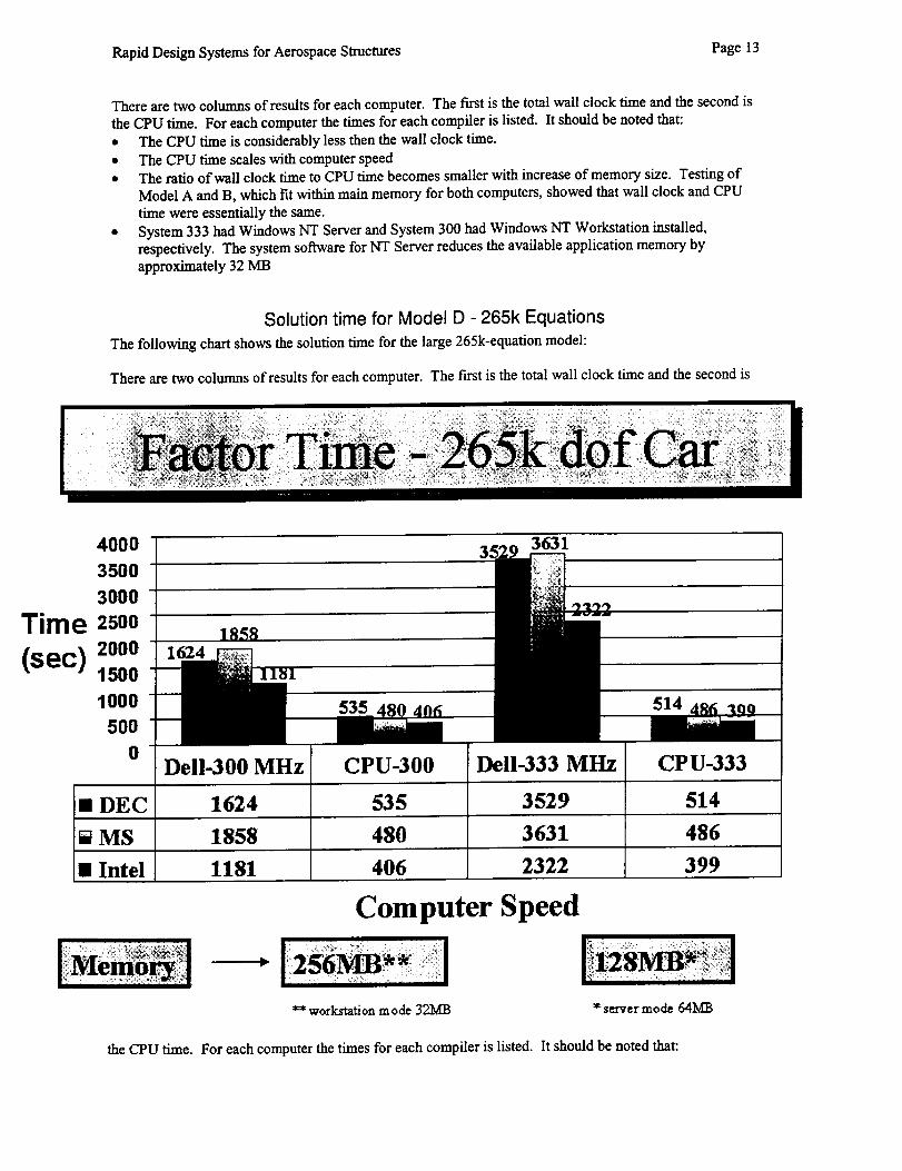
There are two columns of results for each computer. The fast is the total wall clock time and the second is
the CPU time. For each computer the times for each compiler is listed. It should be noted that:
• The CPU time is considerably less then the wall clock time.
• The CPU time scales with computer speed• The ratio of wall clock time to CPU time becomes smaller with increase of memory size. Testing of
Model A and B, which tit within main memory for both computers, showed that wall clock and CPU
time were essentially the same.
• System 333 had Windows NT Server and System 300 had Windows NT Workstation installed,
respectively. The system software for NT Server reduces the available application memory by
approximately 32 MB
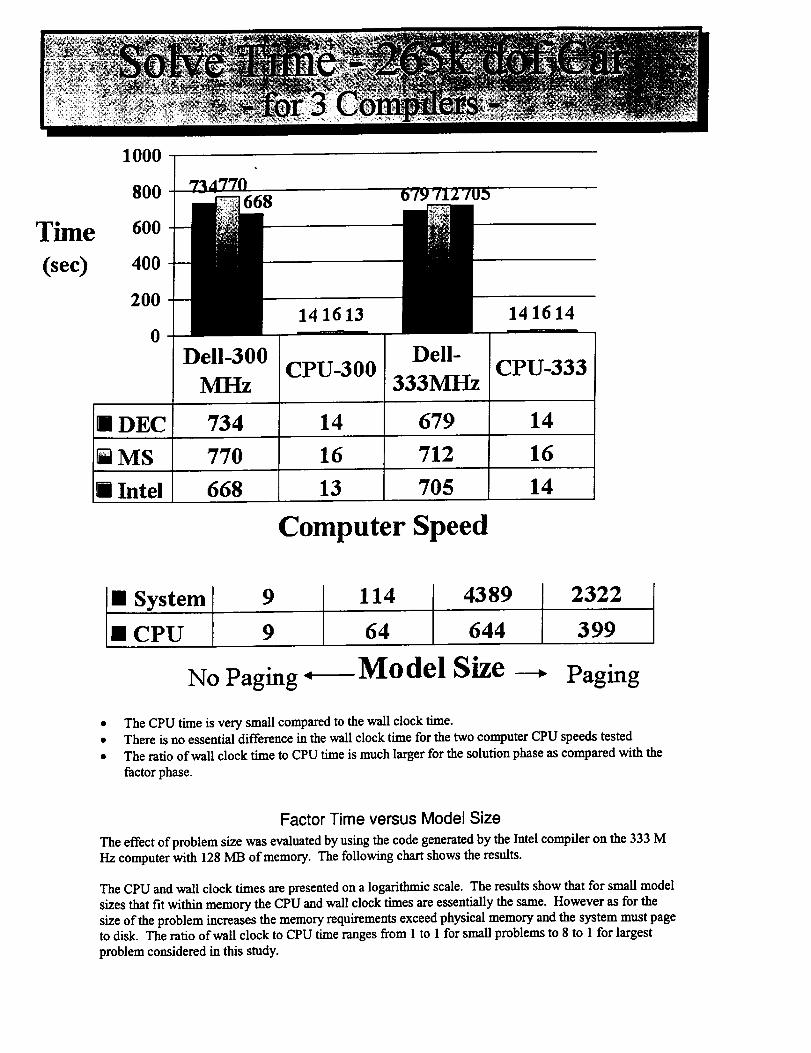
Solution time for Model D - 265k Equations
The following chart shows the solution time for the large 265k-equation model:
There are two columns of results for each computer. The fast is the total wall clock time and the second is
4O00
3500 "
3000 "
Time zsoo-(sec) 2o0o --
1500
10005OO
0Dell-300 MHz CPU-333
• DEC 1624 535 3529 514
[]MS 1858 480 3631 486
• Intel 1181 406 2322 399
Computer Speed
_" workstation mode 32MB " server mode 641d13
the CPU time. For each computer the times for each compiler is listed. It should be noted that:
Thne
(see)
1000
800
600
400
200
0
1 DEC
o7v71270S
Dell-300
14 16 13
Dell-
141614
MHz
734
CPU-300
14
333MHz
679
CPU-333
14
iMS 770 16 712 16
i _tel 668 13 705 14
Computer Speed
I: System 9 114 4389 2322CPU 9 64 644 399
No Paging _ Model --_ Paging
The CPU time is very small compared to the wall clock time.There is no essential difference in the wall clock time for the two computer CPU speeds testedThe ratio of wall clock time to CPU time is much larger for the solution phase as compared with the
factor phase.
Factor Time versus Model Size
The effect of problem size was evaluated by using the code generated by the Intel compiler on the 333 MHz computer with 128 MB of memory. The following chart shows the results.
The CPU and wall clock times are presented on a logarithmic scale. The results show that for small modelsizes that fit within memory the CPU and wall clock times are essentially the same. However as for the
size of the problem increases the memory requirements exceed physical memory and the system must pageto disk. The ratio of wall clock to CPU time ranges from 1 to 1 for small problems to 8 to 1 for largest
problem considered in this study.

Rapid Design Systems for Aerospace Structures Page 15
Observations
The Pentium II (and the Pentium Pro200) chip design leads to very credible performance on PCs. The
factors optimizing solver performance are:
• Proven GPS algorithm that minimizes memory requirement and CPU time.• Windows NT that is 3 time faster than Windows 95.
• Equation reordering method is the major algorithmic factor affecting factor speed.
• Large physical memory reduces paging size. (PC computers currently support 1 gigabyte of main
memory and will support 2 GB in the near future.)• Performance as measured by wall clock to CPU time is better for the factor phase than the solve phase.
• Factor time scales with CPU speed
• The compiler choice can have a significant effect on solution time. The Intel compiler generated
optimized code that was up to two times faster than code generated by other compilers.
Future Research
The model assembly and analysis subsystem are major subsystem in the Intelligent Synthesis Environmentand must support rapid robust simulation repose to the design teams. In order to improve the response of
the analysis subsystem the following tasks are identifies for future research.1. Develop and test the architecture of part-oriented analysis
2. Develop and test course grain parallel processing in the new system architecture3. Continually evaluate GPS performance on latest 32 bit and 64-bit PCs
• Establish a cooperative research and development program with a major PC vendor
• Assess impact of large memory and faster processors4. Develop and implement algorithms to speed response of the GPS subsystem
• Improve reordering algorithms• Improve the solve wall clock to cpu time ratio to be commensurate with that for factorization
5. Evaluate methods for macro parallelism on multi-processor PCs6. Evaluate the Linux operating system and available Fortran compilers as an option to Windows NT