Embed Size (px)
Citation preview

Rev 0.3
October 20, 2008
C/C++ Programming Guide for the FIRST Robotics Competition Worcester Polytechnic Institute Robotics Resource Center
Brad Miller, Ken Streeter, Beth Finn

Contents
Getting Started .............................................................................................................................................. 6
What is the WPI Robotics Library ............................................................................................................ 7
A simple robot program ............................................................................................................................ 9
Using objects ........................................................................................................................................... 10
Creating object instances .................................................................................................................... 11
Creating a Robot Program .......................................................................................................................... 12
Pointers and addresses ............................................................................................................................ 15
Built-in Robot classes ............................................................................................................................. 16
SimpleRobot class ................................................................................................................................... 17
IterativeRobot class ................................................................................................................................. 18
WPI Robotics Library Conventions ........................................................................................................ 19
Class, method, and variable naming ................................................................................................... 19
Constructors with slots and channels .................................................................................................. 19
RobotBase class ...................................................................................................................................... 20
Watchdog timer class .............................................................................................................................. 21
Sensors ........................................................................................................................................................ 22
Types of supported sensors ................................................................................................................. 22
Digital I/O Subsystem ............................................................................................................................. 23
Digital Inputs .......................................................................................................................................... 24
Digital Outputs ........................................................................................................................................ 25
Accelerometer ......................................................................................................................................... 26
Gyro ........................................................................................................................................................ 27
Using the Gyro class ........................................................................................................................... 27
Setting the gyro sensitivity .................................................................................................................. 27
Example .............................................................................................................................................. 27
HiTechnicCompass ................................................................................................................................. 29
Example .............................................................................................................................................. 29
Ultrasonic rangefinder ............................................................................................................................ 30

Example .............................................................................................................................................. 30
Counter Subsystem ................................................................................................................................. 31
Counter Objects ...................................................................................................................................... 32
Encoders .................................................................................................................................................. 33
Example .............................................................................................................................................. 33
Geartooth Sensor ..................................................................................................................................... 34
Example .............................................................................................................................................. 34
Quadrature Encoders ............................................................................................................................... 35
Background Information ..................................................................................................................... 35
Example .............................................................................................................................................. 35
Analog Inputs .......................................................................................................................................... 36
Summary ............................................................................................................................................. 37
Analog Triggers ...................................................................................................................................... 38
3 Point Average Reject Filter .............................................................................................................. 38
Camera .................................................................................................................................................... 39
Camera task management ................................................................................................................... 39
Simple Camera initialization ............................................................................................................... 39
Configurable Camera initialization ..................................................................................................... 39
Image Acquisition .............................................................................................................................. 40
Camera Metrics ................................................................................................................................... 40
Controlling Motors...................................................................................................................................... 41
PWM ....................................................................................................................................................... 42
Victor ...................................................................................................................................................... 43
Example .............................................................................................................................................. 43
Jaguar ...................................................................................................................................................... 44
Use of limit switches ........................................................................................................................... 44
Example .............................................................................................................................................. 44
Servo ....................................................................................................................................................... 45
Example .............................................................................................................................................. 45
RobotDrive .............................................................................................................................................. 46
Example .............................................................................................................................................. 47
Controlling Pneumatics ............................................................................................................................... 48

Compressor ............................................................................................................................................. 49
Example .............................................................................................................................................. 49
Solenoid (Pneumatics) ............................................................................................................................ 50
Example .............................................................................................................................................. 50
Vision / Image Processing .......................................................................................................................... 51
Color Tracking ........................................................................................................................................ 52
Example using defaults ....................................................................................................................... 52
Example using specified ranges .......................................................................................................... 52
Example .............................................................................................................................................. 53
Concurrency ................................................................................................................................................ 54
Creating tasks .......................................................................................................................................... 55
Synchronized and Critical Regions ......................................................................................................... 56
Example .............................................................................................................................................. 56
System Architecture .................................................................................................................................... 58
Digital Sources ........................................................................................................................................ 59
Digital Filter ........................................................................................................................................ 59
Getting Feedback from the Drivers Station ................................................................................................ 60
Joysticks .................................................................................................................................................. 61
Example .............................................................................................................................................. 61
Driver station analog inputs .................................................................................................................... 62
Example .............................................................................................................................................. 62
Driver station digital inputs .................................................................................................................... 63
Example .............................................................................................................................................. 63
Driver station digital outputs .................................................................................................................. 64
Example .............................................................................................................................................. 64
Advanced Programming Topics.................................................................................................................. 65
Using Subversion with Workbench ........................................................................................................ 66
Installing the Subclipse client into Workbench .................................................................................. 66
Getting the WPILib Source Code ........................................................................................................... 70
Importing the WPI Robotics Library into your workspace ................................................................. 70
Using the WPI Robotics Library source code in your projects ........................................................... 72
Replacing WPI Robotics Library parts ................................................................................................... 74

Interrupts ................................................................................................................................................. 75
Example .............................................................................................................................................. 75
Creating your own speed controllers ...................................................................................................... 76
PID Programming ................................................................................................................................... 77
Using the serial port ................................................................................................................................ 78
Relays ...................................................................................................................................................... 79
Customizing analog sampling ................................................................................................................. 80
Using I2C ................................................................................................................................................ 81
Using DMA for data analysis.................................................................................................................. 82
Using Wind River Workbench .................................................................................................................... 83
Setting up the environment ..................................................................................................................... 84
Creating a Remote System in Workbench .......................................................................................... 84
Creating a robot project .......................................................................................................................... 86
Building your project .............................................................................................................................. 88
Downloading the project to the cRIO ..................................................................................................... 89
Debugging your robot program .............................................................................................................. 90
C++ Tips ..................................................................................................................................................... 93
Creating an application in WorkBench ....................................................................................................... 94
Using C with the WPI Robotics Library ..................................................................................................... 95
Contributing to the WPI Robotics Library .................................................................................................. 97
Glossary ...................................................................................................................................................... 98
Index ........................................................................................................................................................... 99

Getting Started What is the WPI Robotics Library
Revision 0.2 – 15 October 2008 6
Getting Started

Getting Started What is the WPI Robotics Library
Revision 0.2 – 15 October 2008 7
What is the WPI Robotics Library The WPI Robotics library is a set of C++ classes that interfaces to the hardware in the FRC
control system and your robot. There are classes to handle sensors, motors, the driver
station, and a number of other utility functions like timing and field management.
The library is designed to:
Deal with all the low level interfacing to these components so you can concentrate on
solving this year’s “robot problem”. This is a philosophical decision to let you focus
on the higher level design of your robot rather than deal with the details of the
processor and the operating system.
Understand everything at all levels by making the full source code of the library
available. You can study (and modify) the algorithms used by the gyro class for
oversampling and integration of the input signal or just ask the class for the current
robot heading. You can work at any level.
First, something about our new environment. We have about 500x more memory and
probably 100x more processor speed over the PIC that we're used to using. The past years
high speed sensor-interrupt logic that required precise coding, hand optimization and lots of
bugs has been replaced with dedicated hardware (FPGA). When the library wants the
number of ticks on a 1000 pulse/revolution optical encoder it just asks the FPGA for the
value. Another example is A/D sampling that used to be done with tight loops waiting for
the conversions to finish. Now sampling across 16 channels is done in hardware.
We chose C++ as a language because we felt it represents a better level of abstraction for
robot programs. C++ (when used properly) also encourages a level of software reuse that is
not as easy or obvious in C. At all levels in the library, we have attempted to design it for
maximum extensibility.
There are classes that support all the sensors, speed controllers, drivers station, etc. that
will be in the kit of parts. In addition most of the commonly used sensors that we could find
that are not traditionally in the kit are also supported, like ultrasonic rangefinders. Another
example are several robot classes that provide starting points for teams to implement their
own robot code. These classes have methods that are called as the program transitions
through the various phases of the match. One class looks like the old easyC/WPILib model
with Autonomous and OperatorControl functions that get filled in and called at the right
time. Another is closer to the old IFI default where user supplied methods are called
continuously, but with much finer control. And the base class for all of these is available for
teams wanting to implement their own versions.
Even with the class library, we anticipate that teams will have custom hardware or other
devices that we haven't considered. For them we have implemented a generalized set of
Getting Started What is the WPI Robotics Library
Revision 0.2 – 15 October 2008 8
hardware and software to make this easy. For example there are general purpose counters
than count any input either in the up direction, down direction, or both (with two inputs).
They can measure the number of pulses, the width of the pulses and number of other
parameters. The counters can also count the number of times an analog signal reaches
inside or goes outside of a set of voltage limits. And all of this without requiring any of that
high speed interrupt processing that's been so troublesome in the past. And this is just the
counters. There are many more generalized features implemented in the hardware and
software.
We also have interrupt processing available where interrupts are routed to functions in your
code. They are dispatched at task level and not as kernel interrupt handlers. This is to help
reduce many of the real-time bugs that have been at the root of so many issues in our
programs in the past. We believe this works because of the extensive FPGA hardware
support.
We have chosen to not use the C++ exception handling mechanism, although it is available
to teams for their programs. Our reasoning has been that uncaught exceptions will unwind
the entire call stack and cause the whole robot program to quit. That didn't seem like a
good idea in a finals match in the Championship when some bad value causes the entire
robot to stop.
The objects that represent each of the sensors are dynamically allocated. We have no way
of knowing how many encoders, motors, or other things a team will put on a robot. For the
hardware an internal reservation system is used so that people don't accidentally reuse the
same ports for different purposes (although there is a way around it if that was what you
meant to do).
I can't say that our library represents the only "right" way to implement FRC robot
programs. There are a lot of smart people on teams with lots of experience doing robot
programming. We welcome their input; in fact we expect their input to help make this
better as a community effort. To this end all of the source code for the library will be
published on a server. We are in the process of setting up a mechanism where teams can
contribute back to the library. And we are hoping to set up a repository for teams to share
their own work. This is too big for a few people to have exclusive control, we want this
software to be developed as a true open source project like Linux or Apache.

Getting Started A simple robot program
Revision 0.2 – 15 October 2008 9
A simple robot program Creating a robot program has been designed to be as simple as possible while still allowing a lot of
flexibility. Here’s an example of a template that represents the simplest robot program you can create.
#include "WPILib.h"
class RobotDemo : public SimpleRobot
{
RobotDemo(void)
{
// put initialization code here
}
void Autonomous(void)
{
// put autonomous code here
}
void OperatorControl(void)
{
// put operator control code here
}
};
START_ROBOT_CLASS(RobotDemo);
There are several templates that can be used as starting points for writing robot programs. This one,
SimpleRobot is probably the easiest to use. Simply add code for initializing sensors and anything else you
need in the constructor, code for your autonomous program in the Autonomous function, and the code for
your operator control part of the program in OperatorControl.
SimpleRobot is actually the name of a C++ class or object that is used as the base of this robot program
called RobotDemo. To use it you create a subclass which is another name for your object that is based on
the SimpleRobot class. By making a subclass, the new class, RobotDemo, inherits all the predefined
behavior and code that is built into SimpleRobot.
Getting Started Using objects
Revision 0.2 – 15 October 2008 10
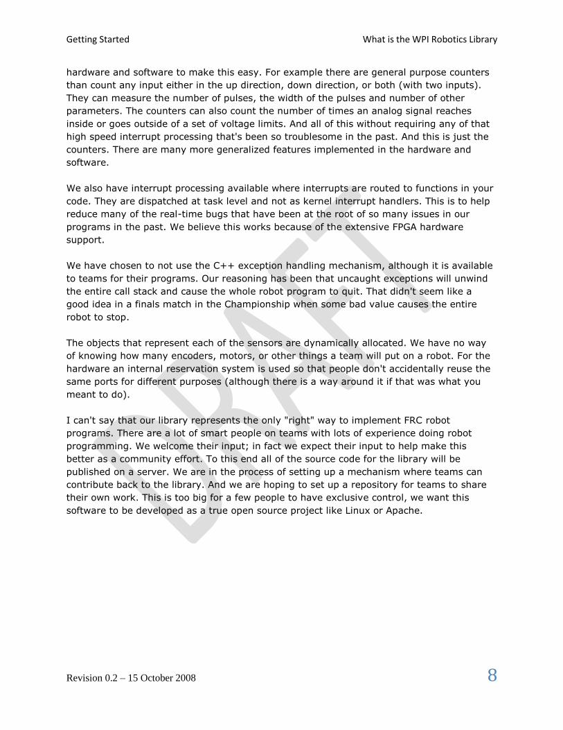
Using objects In the WPI Robotics Library all sensors, motors, driver station elements, and more are all objects. For the
most part, objects are the physical things on your robot. Objects include the code and the data that makes
the thing operate. Let’s look at a Gyro. There are a bunch of operations, or methods, you can perform on a
gyro:
Create the gyro object – this sets up the gyro and causes it to initialize itself
Get the current heading, or angle, from the gyro
Set the type of the gyro, its Sensitivity
Reset the current heading to zero
Delete the gyro object when you’re done using it
Creating a gyro object is done like this:
Gyro robotHeadingGyro(1);
robotHeadingGyro is a variable that holds the Gyro object that represents a gyro module connected to
analog port 1. That’s all you have to do to make an instance of a Gyro object.
Note: by the way, an instance of an object is the chunk of memory that represents the
data unique to that object. When you create an object that memory is allocated
and when the object is deleted, that memory is deallocated.
To get the current heading from the gyro, you simply call the GetAngle method on the gyro object.
Calling the method is really just calling a function that works on the data specific to that gyro instance.
float heading = robotHeadingGyro.GetAngle();
The variable heading will be set to the current heading of the gyro connected to analog channel 1.

Getting Started Using objects
Revision 0.2 – 15 October 2008 11
Creating object instances
There are several ways of creating object instances used throughout the WPI Robotics Library and all the
examples. Depending on how the object is created there are differences in how the object is referenced
and deleted. Here are the rules:
Method Creating object Using the object When the object is
deleted
Local variable
declared inside a
block or function
Victor leftMotor(3); leftMotor.Set(1.0); Object is implicitly
deallocated when the
enclosing block is
exited
Global declared
outside of any
enclosing blocks
or functions; or a
static variable
Victor leftMotor(3); leftMotor.Set(1.0); Object is not
deallocated until the
program exits
Pointer to object
Victor *leftMotor = new Victor(3); leftMotor->Set(1.0); Object must be
explicitly deallocated
using the C++ delete
operator.
How do you decide what to use?

Creating a Robot Program Using objects
Revision 0.2 – 15 October 2008 12
Creating a Robot Program Now consider a very simple robot program that has these characteristics:
Autonomous period Drives in a square pattern by driving half speed for 2 seconds to make a side then
turns 90 degrees. This is repeated 4 times.
Operator Control
period
Uses two joysticks to provide tank steering for the robot.
The robot specifications are:
Left drive motor PWM port 1
Right drive motor PWM port 2
Joystick driver station joystick port 1
Starting with the template for a simple robot program we have:
#include "WPILib.h"
class RobotDemo : public SimpleRobot
{
RobotDemo(void)
{
// put initialization code here
}
void Autonomous(void)
{
// put autonomous code here
}
void OperatorControl(void)
{
// put operator control code here
}
};
START_ROBOT_CLASS(RobotDemo);
Now add objects to represent the motors and joystick.
The two objects – the robot drive with motors in ports 1 and 2, and joystick is declared using the
following code:
RobotDrive drive(1, 2);
Joystick stick(1);

Creating a Robot Program Using objects
Revision 0.2 – 15 October 2008 13
For the example and to make the program easier to understand, we’ll disable the watchdog timer. This is a
feature in the WPI Robotics Library that helps ensure that your robot doesn’t run off out of control if the
program malfunctions.
RobotDemo(void)
{
GetWatchdog().SetEnabled(false);
}
Now the autonomous part of the program can be constructed that drives in a square pattern:
void Autonomous(void)
{
for (int i = 0; i < 4; i++)
{
drivetrain.Drive(0.5, 0.0); // drive 50% forward with 0% turn
Wait(2000); // wait 2000 ms (2 seconds)
drivetrain.Drive(0.0, 0.75); // drive 0% forward and 75% turn
}
Drivetrain.Drive(0.0, 0.0); // drive 0% forward, 0 turn (stop)
}
Now look at the operator control part of the program:
void OperatorControl(void)
{
while (1) // loop forever
{
drivetrain.Tank(&stick1, &stick2); // tank drive with the joystick
}
}
Putting it all together we get this pretty short program that accomplishes some autonomous task and
provides operator control tank steering:

Creating a Robot Program Using objects
Revision 0.2 – 15 October 2008 14
#include "WPILib.h"
RobotDrive drivetrain(1, 2);
Joystick stick(1);
class RobotDemo : public SimpleRobot
{
RobotDemo(void)
{
GetWatchdog().SetEnabled(false);
}
void Autonomous(void)
{
for (int i = 0; i < 4; i++)
{
drivetrain.Drive(0.5, 0.0); // drive 50% forward, 0% turn
Wait(2000); // wait 2000 ms (2 seconds)
drivetrain.Drive(0.0, 0.75); // drive 0% forward and 75% turn
Wait(750); // turn for almost a second
}
drivetrain.Drive(0.0, 0.0); // stop the robot
}
void OperatorControl(void)
{
while (1) // loop forever
{
drivetrain.Tank(&stick1, &stick2); // tank drive with the joystick
}
}
};
START_ROBOT_CLASS(RobotDemo);
Although this program will work perfectly with the robot as described, there were some details that were
skipped:
In the example drivetrain and stick are global variables. In computer science classes you
would be discouraged from doing that. In the next section pointers will be introduced that make
the code more “correct” and maintainable.
The tank steering method drivetrain.tank(&stick) had this &stick construct in it. The
ampersand (&) represents the address of a Joystick object. The next section will describe how
pointers work and what that ampersand really means.
The drivetrain.Drive() method takes two parameters, a speed and a turn direction. See the
documentation about the RobotDrive object for details on how that speed and direction really
work.

Creating a Robot Program Pointers and addresses
Revision 0.2 – 15 October 2008 15
Pointers and addresses

Creating a Robot Program Built-in Robot classes
Revision 0.2 – 15 October 2008 16
Built-in Robot classes There are several built-in robot classes that will help you quickly create a robot program. These are:
Table 1: Built-in robot base classes to create your own robot program. Subclass one of these depending on your requirements and preferences.
Class name Description
SimpleRobot This template is the easiest to use and is designed for writing a straight-line
autonomous routine without complex state machines.
Pros:
Only three places to put your code: the constructor for initialization, the
Autonomous method for autonomous code and the OperatorControl method
for teleop code.
Sequential robot programs are trivial to write, just code each step one after
another.
No state machines required for multi-step operations, the program can
simply do each step sequentially
Cons:
Automatic switching between Autonomous and Teleop code segments is
not easy and may require rebooting the controller.
The Autonomous method will not quit running until it exits, so it will
continue to run through the TeleOp period unless it finishes by the end of
the Autonomous period.
IterativeRobot This template gives additional flexibility in the code for responding to various field
state changes in exchange for additional complexity in the program design. It is
based on a set of methods that are repeatedly called based on the current state of the
field. The intent is that each method is called; it does some processing, and then
returns. That way, if the field state changes, a different method can be called as soon
as the change happens.
Pros:
Can have very fine-grain control of field state changes, especially if
practicing and retesting the same state over and over.
Cons:
More difficult to write simple complex tasks. It requires state variables to
remember what the robot is doing from one call the next.
RobotBase The base class for the above classes. This provides all the basic functions for field
control, the user watchdog timer, and robot status. This class should be extended to
have the required specific behavior.

Creating a Robot Program SimpleRobot class
Revision 0.2 – 15 October 2008 17
SimpleRobot class The SimpleRobot class is designed to be the base class for a robot program with straightforward
transitions from Autonomous to Operator Control periods. There are three methods that are usually filled
in to complete a SimpleRobot program.
Table 2: SimpleRobot class methods that are called as the match moves through each phase.
Method What it does
the Constructor
(method with the
same name as the
robot class)
Put all the code in the constructor to initialize sensors and any program variables
that you have. This code runs as soon as the robot is turned on, but before it is
enabled. When the constructor exits, the program waits until the robot is enabled.
Autonomous() All the code that should run during the autonomous period of the game goes in the
Autonomous method. The code is allowed to run to completion and will not be
stopped at the end of the autonomous period. If the code has an infinite loop, it will
never stop running until the entire match ends. When the method exits, the
program will wait until the start of the operator control period.
OperatorControl() Put code in the OperatorControl method that should run during the operator control
part of the match. This method will be called after the Autonomous() method has
exited and the field has switched to the operator control part of the match. If your
program exits from the OperatorControl() method, it will not resume until the robot
is reset.

Creating a Robot Program IterativeRobot class
Revision 0.2 – 15 October 2008 18
IterativeRobot class The IterativeRobot class divides your program up into methods that are repeatedly called at various times
as the robot program executes. For example, the AutonomousContinuous() method is called continuously
while the robot is in the autonomous mode of operation. When the robot changes state to operator control,
then the TeleopInit() first, then the TeleopContinuous() method is called continuously.
WindRiver Workbench has a built in sample robot program based on the Iterative Robot base class. If you
would like to use it, follow the instructions from the previous section, except select “Iterative Robot Main
Program”. The project will be created in your workspace.
The methods that the user fills in when creating a robot based on the IterativeRobot base class are:
Table 3: IterativeRobot class methods that are called as the match proceeds through each phase.
Method name Description
RobotInit Called when the robot is first turned on. This is a substitute for using the
constructor in the class for consistency. This method is only called once.
DisabledInit Called when the robot is first disabled
AutonomousInit Called when the robot enters the autonomous period for the first time. This is
called on a transition from any other state.
TeleopInit Called when the robot enters the teleop period for the first time. This is called
on a transition from any other state.
DisabledPeriodic Called periodically during the disabled time based on a periodic timer for the
class.
AutonomousPeriodic Called periodically during the autonomous part of the match based on a
periodic timer for the class.
TeleopPeriodic Called periodically during the teleoperation part of the match based on a
periodic timer for the class.
DisabledContinuous Called continuously while the robot is disabled. Each time the program
returns from this function, it is immediately called again provided that the
state hasn’t changed.
AutonomousContinuous Called continuously while the in the autonomous part of the match. Each
time the program returns from this function, it is immediately called again
provided that the state hasn’t changed.
TeleopContinuous Called continuously while in the teleop part of the match. Each time the
program returns from this function, it is immediately called again provided
that the state hasn’t changed.
The three Init methods are called only once when that state is entered for the first time. The Continuous
methods are called repeatedly while in that state, after calling the appropriate Init method. The Periodic
methods are called periodically while in a given state where the period can be set using the SetPeriod
method in the IterativeRobot class. The periodic methods are intended for time based algorithms like PID
control. Any of the provided methods will be called at the appropriate time so if there is a TeleopPeriodic
and TeleopContinous, they will both be called.
Creating a Robot Program WPI Robotics Library Conventions
Revision 0.2 – 15 October 2008 19
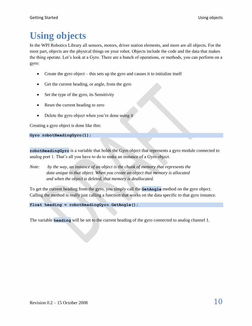
WPI Robotics Library Conventions This section documents some conventions that were used throughout the library to standardize on its
use and make things more understandable. Knowing these should make your programming job much
easier.
Class, method, and variable naming
Names of things follow the following conventions:
Type of name Naming rules Examples
Class name Initial upper case letter then camel case
(mixed upper/lower case) except acronyms
which are all upper case
Victor, SimpleRobot, PWM
Method name Initial upper case letter then camel case StartCompetition, Autonomous,
GetAngle
Member variable “m_” followed by the member variable name
starting with a lower case letter then camel
case
m_deleteSpeedControllers,
m_sensitivity
Constructors with slots and channels
Most constructors for physical objects that connect to the cRIO take the port number in the constructor.
The following conventions are used:
Specification of a port consists of the slot number followed by the channel number. The slot
number is the physical slot on the cRIO chassis that the module is plugged into. For example, for
Analog modules it would be either 1 or 2. The channel number is a number from 1 to n, where n
is the number of channels of that type.
Since many robots can be built with only a single analog or digital module, there is a shorthand
method of specifying port. If the port is on the first (lowest numbered) module, the slot
parameter can be left out.
Examples are:
Jaguar(UINT32 channel); // channel with default slot (4)
Jaguar(UINT32 slot, UINT32 channel); // channel and slot
Gyro(UINT32 slot, UINT32 channel); // channel with explicit slot
Gyro(UINT32 channel); // channel with default slot (1)

Creating a Robot Program RobotBase class
Revision 0.2 – 15 October 2008 20
RobotBase class The RobotBase class is the subclass for the SimpleRobot and IterativeRobot classes. It is intended that if
you decide to create your own type or robot class it will be based on RobotBase. RobotBase has all the
methods to determine the field state, set up the watchdog timer, communications, and other housekeeping
functions.
To create your own base class, create a subclass of RobotBase and implement (at least) the
StartCompetition() method.
For example, the SimpleRobot class definition looks (approximately) like this:
class SimpleRobot: public RobotBase
{
public:
SimpleRobot(void);
virtual void Autonomous(void);
virtual void OperatorControl(void);
virtual void RobotMain(void);
void StartCompetition(void);
private:
bool m_robotMainOverridden;
};
It overrides the StartCompetition() method that controls the running of the other methods and it adds
the Autonomous(), OperatorControl(), and RobotMain() methods. The StartCompetition
method looks (approximately) like this:
void SimpleRobot::StartCompetition(void)
{
while (IsDisabled()) Wait(10); // wait for match to start
if (IsAutonomous()) // if starts in autonomous
{
Autonomous(); // run user supplied Autonomous code
}
while (IsAutonomous()) Wait(10); // wait until end of autonomous period
while (IsDisabled()) Wait(10); // make sure robot is enabled
OperatorControl(); // start user supplied OperatorControl
}
It uses the IsDisabled() and IsAutonomous() methods in RobotBase to determine the field state and
calls the correct methods as the match is sequenced.
Similarly the IterativeRobot class calls a different set of methods as the match progresses.

Creating a Robot Program Watchdog timer class
Revision 0.2 – 15 October 2008 21
Watchdog timer class The Watchdog timer class helps to ensure that the robot will stop operating if the program does something
unexpected or crashes. A watchdog object is created inside the RobotBase class (the base class for all the
robot program templates). Once created, the program is responsible for “feeding” the watchdog
periodically by calling the Feed() method on the Watchdog. Failure to feed the Watchdog results in all
the motors stopping on the robot.
The default expiration time for the Watchdog is 500ms. Programs can override the default expiration time
by calling the SetExpiration(expiration-time-in-ms) method on the Watchdog.
Use of the Watchdog timer is recommended for safety, but can be disabled. For example, during the
autonomous period of a match the robot needs to drive for drive for 2 seconds then make a turn. The
easiest way to do this is to start the robot driving, and then use the Wait function for 2 seconds. During
the 2 second period when the robot is in the Wait function, there is no opportunity to feed the Watchdog.
In this case you could disable the Watchdog at the start of the Autonomous() method and re-enable it at
the end.
void Autonomous(void)
{
GetWatchdog().SetEnabled(false); // disable the watchdog timer
Drivetrain.Drive(0.75, 0.0); // drive straight at 75% power
Wait(2000); // wait for 2 seconds
.
.
.
GetWatchdog().SetEnabled(true); // reenable the watchdog timer
}

Creating a Robot ProgramYou can get the address of the Watchdog timer object from the WPI Robotics Library Conventions
Revision 0.2 – 15 October 2008 22
You can get the address of the Watchdog
timer object from the WPI Robotics Library
Conventions This section documents some conventions that were used throughout the library to standardize on its
use and make things more understandable. Knowing these should make your programming job much
easier.
Class, method, and variable naming
Names of things follow the following conventions:
Type of name Naming rules Examples
Class name Initial upper case letter then camel case
(mixed upper/lower case) except acronyms
which are all upper case
Victor, SimpleRobot, PWM
Method name Initial upper case letter then camel case StartCompetition, Autonomous,
GetAngle
Member variable “m_” followed by the member variable name
starting with a lower case letter then camel
case
m_deleteSpeedControllers,
m_sensitivity
Constructors with slots and channels
Most constructors for physical objects that connect to the cRIO take the port number in the constructor.
The following conventions are used:
Specification of a port consists of the slot number followed by the channel number. The slot
number is the physical slot on the cRIO chassis that the module is plugged into. For example, for
Analog modules it would be either 1 or 2. The channel number is a number from 1 to n, where n
is the number of channels of that type.
Since many robots can be built with only a single analog or digital module, there is a shorthand
method of specifying port. If the port is on the first (lowest numbered) module, the slot
parameter can be left out.
Examples are:

Creating a Robot ProgramYou can get the address of the Watchdog timer object from the WPI Robotics Library Conventions
Revision 0.2 – 15 October 2008 23
Jaguar(UINT32 channel); // channel with default slot (4)
Jaguar(UINT32 slot, UINT32 channel); // channel and slot
Gyro(UINT32 slot, UINT32 channel); // channel with explicit slot
Gyro(UINT32 channel); // channel with default slot (1)
RobotBase class from any of the methods inside one of the robot program template objects.

SensorsYou can get the address of the Watchdog timer object from the WPI Robotics Library Conventions
Revision 0.2 – 15 October 2008 24
Sensors The WPI Robotics Library includes built in support for all the sensors that are supplied in the FRC kit of
parts as well as many other commonly used sensors available to FIRST teams through industrial and
hobby robotics outlets.
Types of supported sensors
The library natively supports sensors of a number of categories shown below.
Category Supported sensors
Wheel/motor position
measurement
Geartooth sensors, encoders, analog encoders, and potentiometers
Robot orientation Compass, gyro, accelerometer, ultrasonic rangefinder
Generic pulse output Counters
In the past high speed counting of pulses of encoders or accurate timing of ultrasonic rangefinders was
implemented in complex real-time software and caused a number of problems as system complexity
increased. On the cRIO, the FPGA implements all the high speed measurements through dedicated
hardware ensuring accurate measurements no matter how many sensors and motors are added to the
robot.
In addition there are many features in the WPI Robotics Library that make it easy to implement many
other types of sensors not directly supported with classes. For example general purpose counters can
measure period and count of any device generating pulses for its output. Another example is a
generalized interrupt facility to catch high speed events without polling and potentially missing them.
Sensors Digital I/O Subsystem
Revision 0.2 – 15 October 2008 25
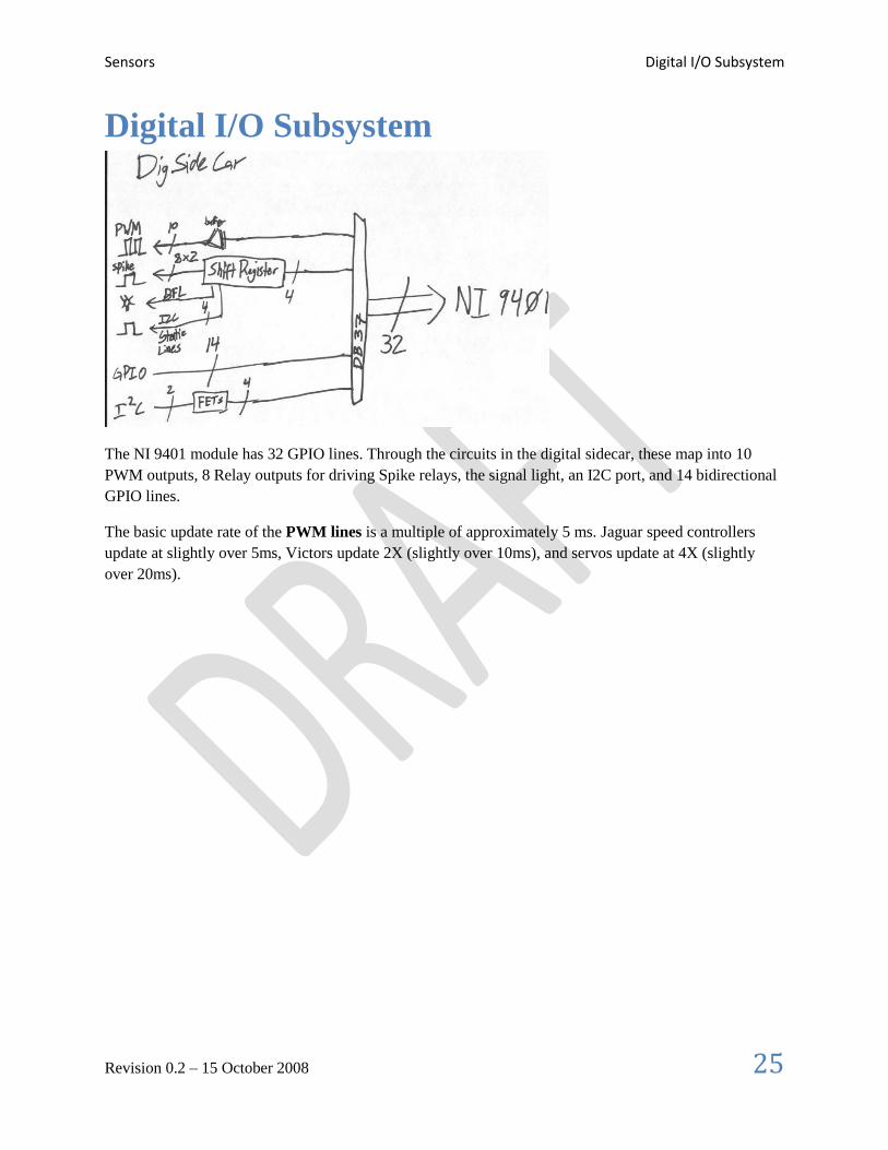
Digital I/O Subsystem
The NI 9401 module has 32 GPIO lines. Through the circuits in the digital sidecar, these map into 10
PWM outputs, 8 Relay outputs for driving Spike relays, the signal light, an I2C port, and 14 bidirectional
GPIO lines.
The basic update rate of the PWM lines is a multiple of approximately 5 ms. Jaguar speed controllers
update at slightly over 5ms, Victors update 2X (slightly over 10ms), and servos update at 4X (slightly
over 20ms).

Sensors Digital Inputs
Revision 0.2 – 15 October 2008 26
Digital Inputs

Sensors Digital Outputs
Revision 0.2 – 15 October 2008 27
Digital Outputs

Sensors Accelerometer
Revision 0.2 – 15 October 2008 28
Accelerometer The accelerometer typically provided in the kit of parts is a two-axis accelerometer. It can provide
acceleration data in the X and Y axis relative to the circuit board. In the WPI Robotics Library you
treat it as two devices, one for the X axis and the other for the Y axis. This is to get better
performance if your application only needs to use one axis. The accelerometer can be used as a tilt
sensor – actually measuring the acceleration of gravity. In this case, turning the device on the side
would indicate 1000 milliGs or one G.
Figure 1: FRC supplied 2 axis accelerometer board connected to a robot

Sensors Gyro
Revision 0.2 – 15 October 2008 29
Gyro Gyros typically supplied by FIRST in the kit of parts are provided by Analog Devices and are actually
angular rate sensors. The output voltage is proportional to the rate of rotation of the axis normal to the
gyro chip top package surface. The voltage is expressed in mV/°/second (degrees/second or rotation
expressed as a voltage). By integrating (summing) the rate output over time the system can derive the
relative heading of the robot.
Another important specification for the gyro is its full scale range. Gyros with high full scale ranges can
measure fast rotation without “pinning” the output. The scale is much larger so faster rotation rates can be
read, but there is less resolution since a much larger range of values is spread over the same number of
bits of digital to analog input. In selecting a gyro you would ideally pick the one that had a full scale
range that exactly matched the fastest rate of rotation your robot would ever experience. That would yield
the highest accuracy possible, provided the robot never exceeded that range.
Using the Gyro class
The Gyro object is typically created in the constructor of the RobotBase derived object. When the Gyro
object is instantiated it will go through a 1 second calibration period to determine the offset of the rate
output while the robot is at rest. This means that the robot must be stationary while this is happening and
that the gyro is unusable until after it has completed the calibration.
Once initialized, the GetAngle() method of the Gyro object will return the number of degrees of
rotation (heading) as a positive or negative number relative to the robot’s position during the calibration
period. The zero heading can be reset at any time by calling the Reset() method on the Gyro object.
Setting the gyro sensitivity
The Gyro class defaults to the settings required for the 80°/sec gyro that was delivered by FIRST in the
kit of parts last year. As soon as we find out if and what type of gyro will be in the kit this year, the
default will change to match it.
To change gyro types call the SetSensitivity(float sensitivity) method and pass it the
sensitivity in volts/°/sec. Just be careful since the units are typically mV (volts / 1000) in the spec sheets.
A sensitivity of 12.5 mV/°/sec would require a SetSensitivity() parameter value of 0.0125.
Example
This program causes the robot to drive in a straight line using the gyro sensor in combination with the
RobotDrive class. The RobotDrive.Drive method takes the speed and the turn rate as arguments; where
both vary from -1.0 to 1.0. The gyro returns a value that varies either positive or negative degrees as the
robot deviates from its initial heading. As long as the robot continues to go straight the heading will be
zero. If the robot were to turn from the 0 degree heading, the gyro would indicate this with either a
positive or negative value. This value is scaled and is used to turn the robot back on course using the
turn parameter of the Drive method.

Sensors Gyro
Revision 0.2 – 15 October 2008 30
class GyroSample : public SimpleRobot
{
RobotDrive myRobot; // robot drive system
Gyro gyro;
public:
GyroSample(void):
myRobot(1, 2), // initialize the sensors in initialization list
gyro(1)
{
GetWatchdog().SetExpiration(100);
}
void Autonomous(void)
{
gyro.Reset();
while (IsAutonomous())
{
GetWatchdog().Feed();
float angle = gyro.GetAngle(); // get heading
myRobot.Drive(-1.0, angle / 30.0); // turn to correct heading
Wait(4);
}
myRobot.Drive(0.0, 0.0); // stop robot
}
};

Sensors HiTechnicCompass
Revision 0.2 – 15 October 2008 31
HiTechnicCompass
Example
Create a compass on the digital module plugged into slot 4. There can only be one i2c sensor plugged
into a digital module.
HiTechnicCompass compass(4);
compVal = compass.GetAngle();
Sensors Ultrasonic rangefinder
Revision 0.2 – 15 October 2008 32
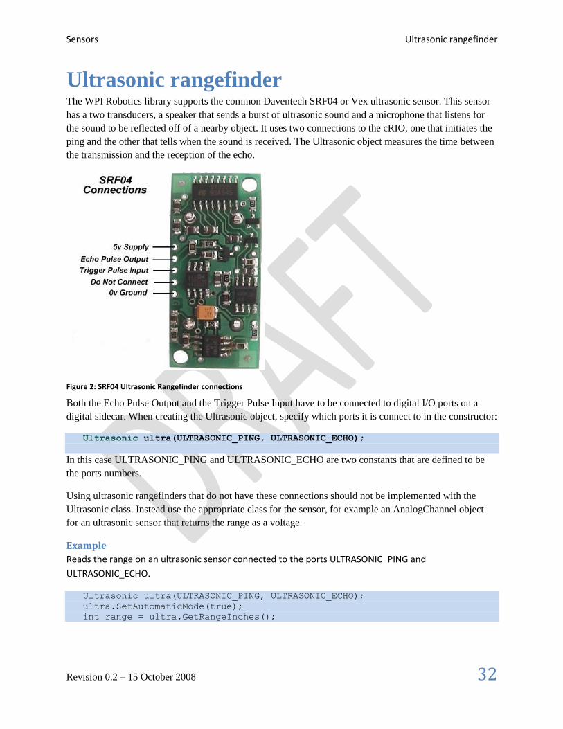
Ultrasonic rangefinder The WPI Robotics library supports the common Daventech SRF04 or Vex ultrasonic sensor. This sensor
has a two transducers, a speaker that sends a burst of ultrasonic sound and a microphone that listens for
the sound to be reflected off of a nearby object. It uses two connections to the cRIO, one that initiates the
ping and the other that tells when the sound is received. The Ultrasonic object measures the time between
the transmission and the reception of the echo.
Figure 2: SRF04 Ultrasonic Rangefinder connections
Both the Echo Pulse Output and the Trigger Pulse Input have to be connected to digital I/O ports on a
digital sidecar. When creating the Ultrasonic object, specify which ports it is connect to in the constructor:
Ultrasonic ultra(ULTRASONIC_PING, ULTRASONIC_ECHO);
In this case ULTRASONIC_PING and ULTRASONIC_ECHO are two constants that are defined to be
the ports numbers.
Using ultrasonic rangefinders that do not have these connections should not be implemented with the
Ultrasonic class. Instead use the appropriate class for the sensor, for example an AnalogChannel object
for an ultrasonic sensor that returns the range as a voltage.
Example
Reads the range on an ultrasonic sensor connected to the ports ULTRASONIC_PING and
ULTRASONIC_ECHO.
Ultrasonic ultra(ULTRASONIC_PING, ULTRASONIC_ECHO);
ultra.SetAutomaticMode(true);
int range = ultra.GetRangeInches();

Sensors Counter Subsystem
Revision 0.2 – 15 October 2008 33
Counter Subsystem The counters subsystem represent a very complete set of digital signal measurement tools for
interfacing with many sensors that you can put on the robot. There are several parts to the counter
subsystem.
Figure 3: Schematic of the possible sources and counters in the Counter Subsystem in the cRIO.
Counters can be triggered by either Analog Triggers or Digital Inputs. The trigger source can either
control up/down counters (Counter objects), quadrature encoders (Encoder objects), or interrupt
generation.
Analog triggers count each time an analog signal goes outside or inside of a set range of voltages.

Sensors Counter Objects
Revision 0.2 – 15 October 2008 34
Counter Objects Counter objects are extremely flexible elements that can count input from either a digital input signal or
an analog trigger. They can also operate in a number of modes based on the type of input signal – some
of which are used to implement other sensors in the WPI Robotics Library.
Gear-tooth mode – enables up/down counting based on the width of an input pulse. This is used
to implement the GearTooth object with direction sensing.
Semi-period mode – counts the period of a portion of the input signal. This is used to measure
the time of flight of the echo pulse in an ultrasonic sensor.
Normal mode – can count edges of a signal in either up counting or down counting directions
based on the input selected.

Sensors Encoders
Revision 0.2 – 15 October 2008 35
Encoders Encoders are devices for measuring the rotation of a spinning shaft. Encoders are typically used to
measure the distance a wheel has turned that can be translated into robot distance across the floor.
Distance moved over a measured period of time represents the speed of the robot and is another common
measurement for encoders. There are several types of encoders supported in WPILib.
Simple encoders
Counter class
Single output encoders that provide a state change as the wheel is
turned. With a single output there is no way of detecting the direction of
rotation. The Innovation First VEX encoder or index outputs of a
quadrature encoder are examples of this type of device.
Quadrature encoders
Encoder class
Quadrature encoders have two outputs typically referred to as the A
channel and the B channel. The B channel is out of phase from the A
channel. By measuring the relationship between the two inputs the
software can determine the direction of rotation.
The system looks for Rising Edge signals (ones where the input is
transitioning from 0 to 1) on the A channel. When a rising edge is
detected on the A channel, the B channel determines the direction. If the
encoder was turning clockwise, the B channel would be a low value and
if the encoder was turning counterclockwise then the B channel would
be a high value. The direction of rotation determines which rising edge
of the A channel is detected, the left edge or the right edge.
Gear tooth sensor
GearTooth class
This is a device supplied by FIRST as part of the FRC robot standard
kit of parts. The gear tooth sensor is designed to monitor the rotation of
a sprocket or gear that is part of a drive system. It uses a Hall-effect
device to sense the teeth of the sprocket as they move past the sensor.
Table 4: Encoder types that are supported by WPILib
These types of encoders are described in the following sections.
Figure 4: Quadrature encoder phase relationships between the two channels.
Example
Sensors Geartooth Sensor
Revision 0.2 – 15 October 2008 36
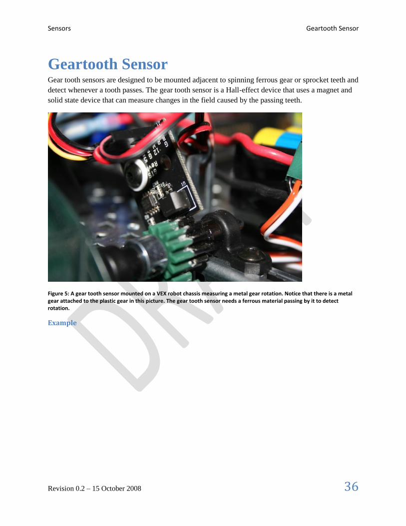
Geartooth Sensor Gear tooth sensors are designed to be mounted adjacent to spinning ferrous gear or sprocket teeth and
detect whenever a tooth passes. The gear tooth sensor is a Hall-effect device that uses a magnet and
solid state device that can measure changes in the field caused by the passing teeth.
Figure 5: A gear tooth sensor mounted on a VEX robot chassis measuring a metal gear rotation. Notice that there is a metal gear attached to the plastic gear in this picture. The gear tooth sensor needs a ferrous material passing by it to detect rotation.
Example

Sensors Quadrature Encoders
Revision 0.2 – 15 October 2008 37
Quadrature Encoders
Background Information
Encoders are devices for measuring the rotation of a spinning shaft. Encoders are typically used to measure the distance a wheel has turned that can be translated into robot distance across the floor. Distance moved over a measured period of time represents the speed of the robot and is another common measurement for encoders. Encoders typically have a rotating disk with slots that spins in front of a photodetector. As the slots pass the detector, pulses are generated on the output. The rate at which the slots pass the detector determines the rotational speed of the shaft and the number of slots that have passed the detector determine the number of rotations (or distance).
Figure 6: A Grayhill quadrature optical encoder. Note the two connectors, one for the A channel and one for the B channel.
Some quadrature encoders have an extra Index channel. This channel pulses once for each complete
revolution of the encoder shaft. If counting the index channel is required for the application it can be done
by connecting that channel to a simple Counter object which has no direction information.
Quadrature encoders are handled by the Encoder class. Using a quadrature encoder is done by simply
connecting the A and B channels to two digital I/O ports and assigning them in the constructor for
Encoder.
Encoder encoder(1, 2, true);
Where 1 and 2 are the port numbers for the two digital inputs and the true value tells the encoder to not
invert the counting direction. The sensed direction could depend on how the encoder is mounted relative
to the shaft being measured.
Example

Sensors Analog Inputs
Revision 0.2 – 15 October 2008 38
Analog Inputs The Analog to Digital converter system has a number of features not available on simpler controllers. It
will automatically sample the analog channels in a round-robin fashion providing an aggregate sample
rate of 500 ks/s (500,000 samples / second). These channels can be optionally oversampled and averaged
to provide the value that is used by the program. There are raw integer and voltage outputs available in
addition to the averaged values.
The averaged value is computed by summing a specified number of samples and performing a simple
average. The summed value is divided by the number of samples that are in the average. When the system
averages a number of samples the division results in a fractional part of the answer that is lost in
producing the integer valued result. That fraction represents how close the average values were to the next
higher integer. Oversampling is a technique where extra samples are summed, but not divided down to
produce the average. Suppose the system were oversampling by 16 times – that would mean that the
values returned were actually 16 times larger than the average output.

Sensors Analog Inputs
Revision 0.2 – 15 October 2008 39
To set the number of oversampled and averaged values use the methods:
void SetAverageBits(UINT32 bits);
UINT32 GetAverageBits(void);
void SetOversampleBits(UINT32 bits);
UINT32 GetOversampleBits(void);
The number of averaged and oversampled values are always each a power of 2 (number of bits of
oversampling/averaging). Therefore the number of oversampled or averaged values is 2bits
, where bits is
passed to the methods: SetOversampleBits(bits) and SetAverageBits(bits). The actual rate
that values are produced from the analog input is reduced by the number of averaged and oversampled
values. For example, setting the number of oversampled bits to 4 and the average bits to 2 would reduce
the number of delivered samples by 24+2
, or 64.
The sample rate is fixed per module, so all the channels on a given module must sample at the same
rate. However the averaging and oversampling rates can be changed for each channel. The WPI Robotics
Library will allow the sample rate to be changed once for a module. Changing it to a different value will
result in a runtime error being generated. The use of some sensors (currently just the Gyro) will set the
sample rate to a specific value for the module it is connected to.
Summary
There is one sample rate per module.
The number of oversampled and averaged values is expressed as a power of 2.
The delivered sample rate is reduced by the oversample and average values.
There are only 2 accumulators in the system with a fixed connection to channel 1 on each
analog module.
The returned analog value is 2n times larger than the actual value where n is the number of
oversampled bits. Averaging doesn’t change the returned values, except to average them.
Sensors Analog Triggers
Revision 0.2 – 15 October 2008 40
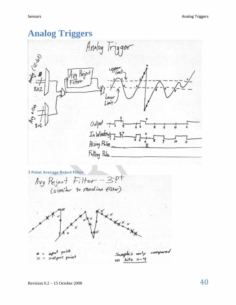
Analog Triggers
3 Point Average Reject Filter

Sensors Camera
Revision 0.2 – 15 October 2008 41
Camera The camera provided in the 2009 kit is the Axis 206. The C camera API provides initialization, control
and image acquisition functionality. A C++ API for the camera is planned for the near future.
Camera task management
A stand-alone task, called FRC_Camera, is responsible for initializing the camera and acquiring images.
It needs to be started in the robot code if the camera is to be used. Normally the task is left running, but if
desired it may be stopped. The activity of image acquisition may also be controlled, for example if you
only want to use the camera in Autonomous mode, you may either call StopCameraTask() to end the task
or call StopImageAcquisition() to leave the task running but not reading images from the camera.
Simple Camera initialization
StartCameraTask() initializes the camera to serve MJPEG images using the following defaults:
Frame Rate = 10 frames / sec Compression = 0 Resolution = 160x120 Rotation = 0 Decode JPEG = yes (change to no if only sending images to PC with no cRIO image processing)
if (StartCameraTask() == -1) {
dprintf( LOG_ERROR,"Failed to spawn camera task; Error code %i",
GetErrorText(GetLastError()) );
}
Configurable Camera initialization
Image processing places a load on the cRIO which may or may not interfere with your other robot code.
Depending on needed speed and accuracy of image processing, it is useful to configure the camera for
performance and placement. The highest frame rates may acquire images faster than your processing
code can process them, especially with higher resolution images. If your camera mount is up-side down or
sideways, adjusting the Image Rotation in the start task command will compensate and images will look
the same as if the camera was mounted right side up. If “decode” is left out of the call, it will default to
ON. You may want to set it OFF only if you are sending images to the PC and not doing any image
processing on the cRIO.
int frameRate = 15; // valid values 0 - 30
int compression = 0; // valid values 0 – 100
ImageSize resolution = k160x120; // k160x120, k320x240, k640480
ImageRotation rot = ROT_180; // ROT_0, ROT_90, ROT_180, ROT_270
int decode = 1; // 1 = decode JPEG for image processing
StartCameraTask(frameRate, compression, resolution, rot, decode);

Sensors Camera
Revision 0.2 – 15 October 2008 42
Image Acquisition
Images of types IMAQ_IMAGE_HSL, IMAQ_IMAGE_RGB, and IMAQ_IMAGE_U8 (gray scale) may
be acquired from the camera. To obtain an image for processing, first create the image structure and then
call GetImage() to get the image and the time that it was received from the camera:
double timestamp;
Image* cameraImage = frcCreateImage(IMAQ_IMAGE_HSL);
if (!cameraImage) { printf(“error: %s”, GetErrorText(GetLastError()) };
if ( !GetImage(cameraImage, ×tamp) ) {
printf(“error: %s”, GetErrorText(GetLastError()) };
The previous call returns the most recent image, regardless of whether it has been previously accessed.
Your code can check the timestamp to see if you have already processed the image.
Alternatively, a blocking call is available which will wait until a new image is available if the current one
has already been served. To prevent excessive blocking time, the call will return unsuccessfully if a new
image is not available in 0.5 second.
Image* cameraImage = frcCreateImage(IMAQ_IMAGE_HSL);
double timestamp;
double lastImageTimestamp
int success = GetImage(cameraImage, ×tamp, lastImageTimestamp);
Camera Metrics
Various camera instrumentation counters used internally may be accessed that may be useful for camera
performance analysis and error detection. Here is a list of the metrics:
CAM_STARTS, CAM_STOPS, CAM_NUM_IMAGE, CAM_BUFFERS_WRITTEN,
CAM_BLOCKING_COUNT, CAM_SOCKET_OPEN, CAM_SOCKET_INIT_ATTEMPTS,
CAM_BLOCKING_TIMEOUT, CAM_GETIMAGE_SUCCESS, CAM_GETIMAGE_FAILURE,
CAM_STALE_IMAGE, CAM_GETIMAGE_BEFORE_INIT, CAM_GETIMAGE_BEFORE_AVAILABLE,
CAM_READ_JPEG_FAILURE, CAM_PC_SOCKET_OPEN, CAM_PC_SENDIMGAGE_SUCCESS,
CAM_PC_SENDIMAGE_FAILURE, CAM_PID_SIGNAL_ERR, CAM_BAD_IMAGE_SIZE,
CAM_HEADER_ERROR
The following example call gets the number of images served by the camera:
int result = GetCameraMetric(CAM_NUM_IMAGE);

Controlling Motors Camera
Revision 0.2 – 15 October 2008 43
Controlling Motors The WPI Robotics library has extensive support for motor control. There are a number of classes that
represent different types of speed controls and servos. The library is designed to support non-PWM motor
controllers that will be available in the future. The WPI Robotics Library currently supports two classes
of speed controllers, PWM-based motors (Jaguars or Victors) and servos.
Motor speed controller values floating point and range from -1.0 to +1.0 where -1.0 is full speed in one
direction, and 1.0 is full speed in the other direction. 0.0 represents stopped. Motors can also be set to
disabled, where the signal is no longer sent to the speed controller.
There are a number of motor controlling classes as part of this group:
Type Usage
PWM Base class for all the pwm-based speed controllers and servos
Victor Speed controller supplied by Innovation First commonly used robotics competitions
with a 10ms update rate.
Jaguar Advanced speed controller used for 2009 and future FRC competitions with a 5ms
update rate.
Servo Class designed to control small hobby servos as typically supplied in the FIRST kit of
parts.
RobotDrive General purpose class for describing a robot base with either 2 or 4 drive motors. Once
defined a number of operations that can be done with that base. Useful for both
autonomous and teleoperated driving.

Controlling Motors PWM
Revision 0.2 – 15 October 2008 44
PWM The PWM class is the base class for devices that operate on PWM signals and is the connection to the
PWM generation hardware in the cRIO. It is not intended to be used directly on a speed controller or
servo. The PWM class has shared code for Victor, Jaguar, and Servo to set the update rate, deadband
elimination, and profile shaping of the output signal.

Controlling Motors Victor
Revision 0.2 – 15 October 2008 45
Victor The Victor class represents the Victor speed controllers provided by Innovation First. They have a
minimum 10ms update rate and only take a PWM control signal. The minimum and maximum values that
will drive the Victor speed control vary from one unit to the next. You can fine tune the values for a
particular speed controller by using a simple program that steps the values up and down in single raw unit
increments. You need the following values:
Value Description
Max The maximum value where the motors stop changing speed and the light on the
Victor goes to full green.
DeadbandMax The value where the motor just stops operating.
Center The value that is in the center of the deadband that turns off the motors.
DeadbandMin The value where the motor just starts running in the opposite direction.
Min The minimum value (highest speed in opposite direction) where the motors stop
changing speed and the light on the Victor goes to .
With these values, call the SetBounds method on the created Victor object.
void SetBounds(INT32 max,
INT32 deadbandMax,
INT32 center,
INT32 deadbandMin,
INT32 min);
Example
Controlling Motors Jaguar
Revision 0.2 – 15 October 2008 46
Jaguar The Jaguar class supports the Luminary Micro Jaguar speed controller. It has an update rate of slightly
over 5ms and currently uses only PWM output signals. In the future the more sophisticated Jaguar speed
controllers might have other methods for control of its many extended functions.
The input values for the Jaguar range from -1.0 to 1.0 for full speed in either direction with 0 representing
stopped.
Use of limit switches
Example

Controlling Motors Servo
Revision 0.2 – 15 October 2008 47
Servo The Servo class supports the Hitechnic servos supplied by FIRST. They have a 20ms update rate and are
controlled by PWM output signals.
The input values for the Servo range from 0.0 to 1.0 for full rotation in one direction to full rotation in the
opposite direction. There is also a method to set the servo angle based on the (currently) fixed minimum
and maximum angle values.
Example
The following code fragment rotates a servo through its full range in 10 steps:
Servo servo(3); // create a servo on PWM port 3 on the first module
float servoRange = servo.GetMaxAngle() - servo.GetMinAngle();
for (float angle = servo.GetMinAngle(); // step through range of angles
angle < servo.GetMaxAngle();
angle += servoRange / 10.0)
{
servo.SetAngle(angle); // set servo to angle
Wait(1000); // wait 1 second
}

Controlling Motors RobotDrive
Revision 0.2 – 15 October 2008 48
RobotDrive The RobotDrive class is designed to simplify the operation of the drive motors based on a model of the
drive train configuration. The idea is to describe the layout of the motors. Then the class can generate all
the speed values to operate the motors for different situations. For cases that fit the model it provides a
significant simplification to standard driving code. For more complex cases that aren’t directly supported
by the RobotDrive class it may be subclassed to add additional features or not used at all.
To use it, create a RobotDrive object specifying the left and right motors on the robot:
RobotDrive drive(1, 2); // left, right motors on ports 1,2
Or
RobotDrive drive(1, 2, 3, 4); // four motor drive case
This sets up the class for a 2 motor configuration or a 4 motor configuration. There are additional
methods that can be called to modify the behavior of the setup.
SetInvertedMotor(kFrontLeftMotor);
This method sets the operation of the front left motor to be inverted. This might be necessary depending
on the gearing of your drive train.
Once set up, there are methods that can help with driving the robot either from the Driver Station controls
or through programmed operation:
Method Description
Drive(speed, turn) Designed to take speed and turn values ranging from -1.0 to 1.0.
The speed values set the robot overall drive speed, positive
values forward and negative values backwards. The turn value
tries to specify constant radius turns for any drive speed. The
negative values represent left turns and the positive values
represent right turns.
TankDrive(leftStick, rightStick) Takes two joysticks and controls the robot with tank steering
using the y-axis of each joystick. There are also methods that
allow you to specify which axis is used from each stick.
ArcadeDrive(stick) Takes a joystick and controls the robot with arcade (single stick)
steering using the y-axis of the joystick for forward/backward
speed and the x-axis of the joystick for turns. There are also
other methods that allow you to specify different joystick axis.
HolonomicDrive(magnitude,
direction, rotation)
Takes floating point values, the first two are a direction vector
the robot should drive in. The third parameter, rotation, is the
independent rate of rotation while the robot is driving. This is
intended for robots with 4 Mecanum wheels independently
controlled.
SetLeftRightMotorSpeeds(leftSpeed,
rightSpeed)
Takes two values for the left and right motor speeds. As with all
the other methods, this will control the motors as defined by the
constructor.

Controlling Motors RobotDrive
Revision 0.2 – 15 October 2008 49
The Drive method of the RobotDrive class is designed to support feedback based driving. Suppose you
want the robot to drive in a straight line. There are a number of strategies, but two examples are using
GearTooth sensors or a gyro. In either case an error value is generated that tells how far from straight the
robot is currently tracking. This error value (positive for one direction and negative for the other) can be
scaled and used directly with the turn argument of the Drive method. This causes the robot to turn back to
straight with a correction that is proportional to the error – the larger the error, the greater the turn.
Example

Controlling Pneumatics RobotDrive
Revision 0.2 – 15 October 2008 50
Controlling Pneumatics There are several classes that will make it easier to use pneumatics in your robot.
Class Purpose
Solenoid Can control pneumatic actuators directly without the need for an additional relay. In
the past a Spike relay was required along with a digital output to control pneumatics
components.
Compressor Keeps the pneumatics system charged by using a pressure switch and software to turn
the compressor on and off as needed.

Controlling Pneumatics Compressor
Revision 0.2 – 15 October 2008 51
Compressor The Compressor class is designed to operate the FRC supplied compressor on the robot. A Compressor
object is constructed with 2 inputs:
The Spike (relay) port that is controlling the power to the compressor
The Digital input that the pressure switch is connected to that is monitoring the accumulator
pressure
The Compressor class will automatically create a task that runs in the background twice a second and
turns the compressor on or off based on the pressure switch value. If the system pressure is above the high
set point, the compressor turns off. If the pressure is below the low set point the compressor turns on.
To use the Compressor class create an instance of the Compressor object and start it. This is typically
done in the constructor for your Robot Program. Once started, it will continue to run on its own with no
further programming necessary. If you do have an application where the compressor should be turned off,
possibly during some particular phase of the game play, you can stop and restart the compressor using the
Start() and Stop() methods.
The compressor class will create instances of the DigitalInput and Relay objects internally to read the
pressure switch and operate the Spike.
Example
Suppose you had a compressor and a Spike relay connected to Relay port 2 and the pressure switch
connected to digital input port 4. Both of these ports are connected to the primary digital input module.
You could create and start the compressor running in the constructor of your RobotBase derived object
using the following 2 lines of code.
Compressor *c = new Compressor(4, 2);
c->Start();
Note: The variable c is a pointer to a compressor object and the
object is allocated using the new operator. If it were allocated as a local
variable in the constructor, at the end of the function the local variables
would be deallocated and the compressor would stop operating.
That’s all that is required to enable the compressor to operate for the duration of the robot program.

Controlling Pneumatics Solenoid (Pneumatics)
Revision 0.2 – 15 October 2008 52
Solenoid (Pneumatics) The Solenoid object controls the outputs of the 9472 Digital Ouput Module. It is designed to apply an
input voltage to any of the 8 outputs. Each output can provide up to 1A of current. The module is
designed to operate 12v pneumatic solenoids used on FIRST robots. This makes the use of relays
unnecessary for pneumatic solenoids.
Note: The 9472 Digital Output Module does not provide enough
current to operate a motor or the compressor so relays connected to
Digital Sidecar digital outputs will still be required for those
applications.
The port numbers on the Solenoid class range from 1-8 as printed on the pneumatic bumper breakout
board.
Note: The 9472 indicator lights are numbered 0-7 for the 8 ports
which is different numbering then used by the class or the pneumatic
bumper case silkscreening.
Example
Setting the output values of the Solenoid objects to true or false will turn the outputs on and off
respectively. The following code fragment will create 8 Solenoid objects, initialize each to true (on), and
then turn them off, one per second. Then it turns them each back on, one per second, and deletes the
objects.
Solenoid *s[8];
for (int i = 0; i < 8; i++)
s[i] = new Solenoid(i + 1); // allocate the Solenoid objects
for (int i = 0; i < 8; i++)
{
s[i]->Set(true); // turn them all on
}
for (int i = 0; i < 8; i++)
{
s[i]->Set(false); // turn them each off in turn
Wait(1000);
}
for (int i = 0; i < 8; i++)
{
s[i]->Set(true); // turn them back on in turn
Wait(1000);
delete s[i]; // delete the objects
}
You can observe the operation of the Solenoid class by looking at the indicator lights on the 9472 module.

Vision / Image Processing Solenoid (Pneumatics)
Revision 0.2 – 15 October 2008 53
Vision / Image Processing Access to National Instrument’s nivison library for machine vision enables automated image processing
for color identification, tracking and analysis. The VisionAPI.cpp file provides open source C wrappers
to a subset of the proprietary library. The full specification for the simplified FRC Vision programming
interface is in the FRC Vision API Specification document. Programmers may also call directly into the
library by including nivision.h and using calls documented in the NI Vision for LabWindows/CVI User
Manual. The FRC Vision interface also includes routines for high level calls for color tracking.
Naming conventions for the vision processing wrappers are slightly different from the rest of WPILib. C
routines prefixed with “imaq” belong to NI’s LabVIEW/CVI vision library. Routines prefixed with “frc”
are simplified interfaces to the vision library provided by BAE Systems for FIRST Robotics Competition
use.
Image files may be read and written to the cRIO non-volatile memory. File types supported are PNG,
JPEG, JPEG2000, TIFF, AIDB, and BMP. Images may also be obtained from the Axis 206 camera.
Images may be copied, cropped, or scaled larger/smaller. Intensity measurements functions available
include calculating a histogram for color or intensity and obtaining values by pixel. Contrast may be
improved by equalizing the image. Specific color planes may be extracted. Thresholding and filtering
based on color and intensity characteristics are used to separate particles that meet specified criteria.
These particles may then be analyzed to find the characteristics.

Vision / Image Processing Color Tracking
Revision 0.2 – 15 October 2008 54
Color Tracking High level calls provide color tracking capability without having to call directly into the image processing
routines. You can either specify a hue range and light setting, or pick specific ranges for hue, saturation
and luminance for target detection.
Example using defaults
Call GetTrackingData() with a color and type of lighting to obtain default ranges that can be used in the
call to FindColor(). The ParticleAnalysisReport returned by FindColor() specifies details of the largest
particle of the targeted color.
TrackingThreshold tdata = GetTrackingData(BLUE, FLUORESCENT);
ParticleAnalysisReport par;
if (FindColor(IMAQ_HSL, &tdata.hue, &tdata.saturation,
&tdata.luminance, &par)
{
printf(“color found at x = %i, y = %i",
par.center_mass_x_normalized, par.center_mass_y_normalized);
printf(“color as percent of image: %d",
par.particleToImagePercent);
}
The normalized center of mass of the target color is a range from –1.0 to 1.0, regardless of image size.
Example using specified ranges
To manage your own values for the color and light ranges, you simply create Range objects:
Range hue, sat, lum;
hue.minValue = 140; // Hue
hue.maxValue = 155;
sat.minValue = 100; // Saturation
sat.maxValue = 255;
lum.minValue = 40; // Luminance
lum.maxValue = 255;
FindColor(IMAQ_HSL, &hue, &sat, &lum, &par);
Tracking also works using the Red, Green, Blue (RGB) color space, however HSL gives more consistent
results for a given target.

Vision / Image Processing Color Tracking
Revision 0.2 – 15 October 2008 55
Example
Here is an example program that enables the robot to drive towards a green target. When it is too close
or too far, the robot stops driving. Steering like this is quite simple as shown in the example. The
example assumes that a RobotDrive object has been set up called myRobot.
The following declarations in the class are used for the example:
RobotDrive *myRobot
Range greenHue, greenSat, greenLum;
This is the initialization of the RobotDrive object, the camera and the colors for tracking the target. It
would typically go in the RobotBase derived constructor.
if (StartCameraTask() == -1) {
printf( "Failed to spawn camera task; Error code %s",
GetErrorText(GetLastError()) );
}
myRobot = new RobotDrive(1, 2);
// values for tracking a target - may need tweaking in your environment
greenHue.minValue = 65; greenHue.maxValue = 80;
greenSat.minValue = 100; greenSat.maxValue = 255;
greenLum.minValue = 100; greenLum.maxValue = 255;
Here is the code that actually drives the robot in the autonomous period. The code checks if the color
was found in the scene and that it was not too big (close) and not too small (far). If it is in the limits, then
the robot is driven forward full speed (1.0), and with a turn rate determined by the
center_mass_x_normalized value of the particle analysis report.
The center_mass_x_normalized value is 0.0 if the object is in the center of the frame; otherwise it
varies between -1.0 and 1.0 depending on how far off to the sides it is. That is the same range as the
Drive method uses for the turn value. If the robot is correcting in the wrong direction then simply negate
the turn value.
while (IsAutonomous())
{
if ( FindColor(IMAQ_HSL, &greenHue, &greenSat, &greenLum, &par)
&& par.particleToImagePercent < MAX_PARTICLE_TO_IMAGE_PERCENT
&& par.particleToImagePercent > MIN_PARTICLE_TO_IMAGE_PERCENT )
{
myRobot->Drive(1.0, (float)par.center_mass_x_normalized);
}
else myRobot->Drive(0.0, 0.0);
Wait(50);
}
myRobot->Drive(0.0, 0.0);

Concurrency Color Tracking
Revision 0.2 – 15 October 2008 56
Concurrency VxWorks is the operation system that is running inside the cRIO and providing services to the running
robot programs that you write. It provides many operations to support concurrency, or the simultaneous
execution of multiple pieces of the program called tasks. Each task runs is scheduled to run by VxWorks
based on its priority and availability of resources it might be waiting on. For example, if one task does a
Wait(time), then other tasks can run until the time runs out on the waiting task.
WPILib provides some classes to help simplify writing programs that do multitasking. However it should
be stressed that writing multi-tasking code represents one of the most challenging aspects of
programming. It may look simple; but there are many complications that could give your program
unexpected and hard to reproduce errors.

Concurrency Creating tasks
Revision 0.2 – 15 October 2008 57
Creating tasks In your program you may decide to subdivide the work into multiple concurrently running tasks. For
example, you may have a requirement to operate a ball loading mechanism independently of ball
shooter the driving code in your robot. Each of these functions can be split out into its own task to
simplify the overall design of the robot code.

Concurrency Synchronized and Critical Regions
Revision 0.2 – 15 October 2008 58
Synchronized and Critical Regions A critical region is an area of code that is always executed under mutual exclusion, i.e. only one task can
be executing this code at any time. When multiple tasks try to manipulate a single group of shared data
they have to be prevented from executing simultaneously otherwise a race condition is possible. Imagine
two tasks trying to update an array at the same time. Task A reads the count of elements in the array, then
task B changes the count, then task A tries to do something based on the (now incorrect) value of the
count it previously read. This situation is called a race condition and represents one of the most difficult
to find programming bugs since the bug only is visible when the timing of multiple tasks is just right (or
wrong).
Typically semaphores are used to ensure only single task access to the shared data. Semaphores are
operating system structures that control access to a shared resource. VxWorks provides two operations on
semaphores take and give. When you take a semaphore, the code pauses until the semaphore isn’t in use
by another task, then the operating system marks it in use, but your code can now run. You give the
semaphore when you are finished using the shared data. It now lets the next task trying to take the
semaphore run.
Suppose that a function operates on some shared data. Understanding about the bad things that can
happen with race conditions, you take a semaphore at the start of the function and give it at the end. Now
inside the function, the data is protected from inappropriate shared use. Now someone else looks at the
code and decides to change it and puts a return in the middle of the function, not noticing the take and
give. The semaphore is taken, but the corresponding give operation never happened. That means that any
other task waiting on that semaphore will wait forever. This condition is called deadlock.
Example
The Synchronized object is a simple wrapper around semaphores that tries to solve the problem. Here is
an example of how it is used:
{
Synchronized s(semaphore);
// access shared code here
if (condition) return;
// more code here
}
At the start of the block a Synchronized object is allocated. This takes the semaphore. When the block
exits, the object is freed and its destructor is called. Inside the destructor the semaphore is given. Notice
that the destructor will be called no matter how the block is exited. Even if a return is used inside the
block, the destructor is guaranteed to be called by the C++ compiler. This eliminates a common cause of
deadlock.
To make the code even more readable, there are two macros defined by WPILib and used like this:

Concurrency Synchronized and Critical Regions
Revision 0.2 – 15 October 2008 59
CRITICAL_REGION(semaphore)
{
// access shared code here
if (condition) return;
// more code here
}
END_REGION;
These macros just make the code more readable, but the expanded code is identical to the previous
example.

System Architecture Synchronized and Critical Regions
Revision 0.2 – 15 October 2008 60
System Architecture This section describes how the system is put together and how the libraries interact with the base
hardware. It should give you better insight as to how the whole system works and its capabilities.
Note: This is a work in progress, the pictures will be cleaned up and
explanations will be soon added. We wanted to make this available to
you in its raw form rather than leaving it out all together.

System Architecture Digital Sources
Revision 0.2 – 15 October 2008 61
Digital Sources
Digital Filter

Getting Feedback from the Drivers Station Digital Sources
Revision 0.2 – 15 October 2008 62
Getting Feedback from the Drivers Station

Getting Feedback from the Drivers Station Joysticks
Revision 0.2 – 15 October 2008 63
Joysticks
Example

Getting Feedback from the Drivers Station Driver station analog inputs
Revision 0.2 – 15 October 2008 64
Driver station analog inputs
Example

Getting Feedback from the Drivers Station Driver station digital inputs
Revision 0.2 – 15 October 2008 65
Driver station digital inputs
Example

Getting Feedback from the Drivers Station Driver station digital outputs
Revision 0.2 – 15 October 2008 66
Driver station digital outputs
Example

Advanced Programming Topics Driver station digital outputs
Revision 0.2 – 15 October 2008 67
Advanced Programming Topics

Advanced Programming Topics Using Subversion with Workbench
Revision 0.2 – 15 October 2008 68
Using Subversion with Workbench Subversion is a free source code management tool that is designed to track changes to a project as it is
developed. You can save each revision of your code in a repository, go back to a previous revision, and
compare revisions to see what changed. You should install a Subversion client if:
You need access to the WPI Robotics Library source code installed on a Subversion server
You have your own Subversion server for working with your team projects
There are a number of clients that will integrate with Workbench, but we’ve been using Subclipse.
Installing the Subclipse client into Workbench
Subclipse can be downloaded from the internet and installed into Workbench. The following instructions
describe how to do it.
On the help menu, select
“Software updates”, then “Find
and Install”.
Select “Search for new features
to install and click Next.

Advanced Programming Topics Using Subversion with Workbench
Revision 0.2 – 15 October 2008 69
Click, “New Remote Site…” to
add the Subclipse update site.
Enter the information for the
update site and click OK.

Advanced Programming Topics Using Subversion with Workbench
Revision 0.2 – 15 October 2008 70
Now you should see Subclipse
added to the list of “Sites to
include in search:”. Click
“Finish”.
Select the “JavaHL Adapter”
and “Subclipse” from the list
of features to install.

Advanced Programming Topics Using Subversion with Workbench
Revision 0.2 – 15 October 2008 71
Accept the license and click
“Next”.
Click “Finish” and the install
will start. If asked, select
“Install All” in the Verification
window. You should allow
Workbench to restart after
finishing.

Advanced Programming Topics Getting the WPILib Source Code
Revision 0.2 – 15 October 2008 72
Getting the WPILib Source Code The WPI Robotics Library source code is installed on a Subversion server. To get it requires having a
subversion client installed in your copy of Workbench. See Installing the Subclipse client into Workbench
for instructions on how to set it up.
Importing the WPI Robotics Library into your workspace
To get the source code requires setting up a “Repository location” then importing the code. The following
steps show the process.
Right-click in the “Project Explorer” window in
Workbench. Select “Import…”
Choose “Checkout Projects from SVN” and click
next.
Select “Create a new repository location” and click
Next.
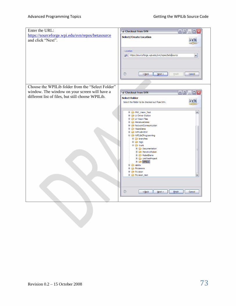
Advanced Programming Topics Getting the WPILib Source Code
Revision 0.2 – 15 October 2008 73
Enter the URL:
https://sourceforge.wpi.edu/svn/repos/betasource
and click “Next”.
Choose the WPILib folder from the “Select Folder”
window. The window on your screen will have a
different list of files, but still choose WPILib.

Advanced Programming Topics Getting the WPILib Source Code
Revision 0.2 – 15 October 2008 74
Check out the code as a project in the Workspace
by leaving all the default options and clicking
“Finish”.
If you are asked for a username and password, it is
your username for SourceForge. Checking the
“Remember password” box will make this easier
since it will ask multiple times.
Using the WPI Robotics Library source code in your projects
The sample projects provided by FIRST use a library file (WPILib.a) and header files from the
Workbench install. If you intend to modify or debug the source copy of the library you just imported, the
project settings have to change to refer to that copy of the library instead.
Note: Before doing these steps you must have built the WPILib project once so that the WPILib.a target
file has been generated.
Right-click on the project name in the “Project Explorer” pane in Workbench and select “Properties”.
In the project properties window,
select “Build Properties”. Here you
can see all the options that
Workbench will use to build your
project.

Advanced Programming Topics Getting the WPILib Source Code
Revision 0.2 – 15 October 2008 75
Select the “Build Paths” tab to use
the downloaded WPILib include
files to your project rather than the
installed version.
Select the Libraries tab and select
the WPILib.a library file from the
downloaded WPILib project instead
of the version preinstalled in
Workbench.
Note: to build WPILib you must install SlikSVN from
http://www.sliksvn.com/en/download. Once downloaded and installed the
builds will run without errors. SlikSVN is a command line interface to
Subversion that our build system uses for tracking library versions.
Now if you rebuild your project it will use the imported version of the WPI Robotics Library rather than
the preinstalled version.

Advanced Programming Topics Replacing WPI Robotics Library parts
Revision 0.2 – 15 October 2008 76
Replacing WPI Robotics Library parts You can replace any component of the WPI Robotics Library with your own version of that component
without having to replace the entire library. When your projects are built, the last step is Linking. This
two step process creates a single executable .OUT file by:
1. Combining all the modules (object files) from your project together into the .OUT file
2. Finding all the unresolved pieces such as classes referenced from WPILib and adding those
pieces to your .OUT file executable.
Only the pieces of WPILib that are unresolved after step 1 are included from the library and that’s the key
to substituting your own version of classes.
Suppose you want to use your own version of the Encoder class because you had some extra features you
wanted to add. To use your version rather than the WPILib version simply:
1. Get the WPILib version of the file (.cpp and .h) files from the WPILib source code and add them
to your project.
2. Make whatever modifications you would like to.
3. Rebuild your project. The library version of the Encoder objects will be included with your set of
object modules, so the linker won’t take the ones in WPILib.

Advanced Programming Topics Interrupts
Revision 0.2 – 15 October 2008 77
Interrupts
Example
Below is a sample program that generates a square wave on a digital output port that is connected to a
digital input port. An interrupt handler is set up on the input port to count the number of cycles.
static int interruptCounter = 0;
// The interrupt handler that counts number of square wave cycles
static void tiHandler(tNIRIO_u32 interruptAssertedMask, void *param)
{
interruptCounter++;
}
void InterruptTestHandler(void)
{
// create the two digital ports (Output and Input)
DigitalOutput digOut(CROSS_CONNECT_A_PORT1);
DigitalInput digIn(CROSS_CONNECT_A_PORT2);
// create the counter that will also count square waves
Counter counter(&digIn);
// initialize the digital output to 0
digOut.Set(0);
// start the counter counting at 0
counter.Reset();
counter.Start();
// register and enable the interrupt handler
digIn.RequestInterrupts(tiHandler);
digIn.EnableInterrupts();
// count 5 times
while (counter.Get() < 5)
{
Wait(1000);
digOut.Set(1);
Wait(1000);
digOut.Set(0);
}
// verify correct operation
if (interruptCounter == 5 && counter.Get() == 5)
printf(“Test passed!\n”);
// free resources
digIn.DisableInterrupts();
digIn.CancelInterrupts();
}
END_TEST(TestInterruptHandler)

Advanced Programming Topics Creating your own speed controllers
Revision 0.2 – 15 October 2008 78
Creating your own speed controllers

Advanced Programming Topics PID Programming
Revision 0.2 – 15 October 2008 79
PID Programming

Advanced Programming Topics Using the serial port
Revision 0.2 – 15 October 2008 80
Using the serial port

Advanced Programming Topics Relays
Revision 0.2 – 15 October 2008 81
Relays

Advanced Programming Topics Customizing analog sampling
Revision 0.2 – 15 October 2008 82
Customizing analog sampling

Advanced Programming Topics Using I2C
Revision 0.2 – 15 October 2008 83
Using I2C

Advanced Programming Topics Using DMA for data analysis
Revision 0.2 – 15 October 2008 84
Using DMA for data analysis

Using Wind River Workbench Using DMA for data analysis
Revision 0.2 – 15 October 2008 85
Using Wind River Workbench Wind River Workbench is a complete C/C++ Interactive Development Environment (IDE) that handles
all aspects of code development. It will help you:
Write the code for your robot with editors, syntax highlighting, formatting, auto-completion, etc.
Compile the source code into binary object code for the cRIO PowerPC architecture.
Debug and test code by downloading the code to the cRIO robot controller and enabling you to
step through line by line and examine variables of the running code.
Deploy the program so that it will automatically start up when the robot is powered on.
You can even use Subversion, a popular source code repository server to manage your code and track
changes. This is especially useful if there is more than one person doing software development.

Using Wind River Workbench Setting up the environment
Revision 0.2 – 15 October 2008 86
Setting up the environment To use Workbench you need to configure it so that it knows about your robot and the programs that you
want to download to it. There are three areas that need to be set up.
1. The target remote system, which is the cRIO that you will use to download and debug your
programs.
2. The run or debug configuration that describes the program to be debugged and which remote
system you want to debug it on.
3. The FIRST Downloader settings that tell which program should be deployed onto the cRO when
you are ready to load it for a competition or operation without the laptop.
Creating a Remote System in Workbench
Workbench connects to your cRIO controller and can download and remotely debug programs running on
it. In order to make that connection, Workbench needs to add your cRIO to its list of Remote Systems.
Each entry in the list tells Workbench the network address of your cRIO and has a kernel file that is
required for remote access. To create the entry for your system do the following steps.
Right-click in the empty area in the “Remote
Systems” window. Select “New Connection”.
In the “Select Remote System Type” window select
“Wind River VxWorks 6.x Target Server
Connection” and click “Next”.

Using Wind River Workbench Setting up the environment
Revision 0.2 – 15 October 2008 87
Fill out the “Target Server Options” window with
the IP address of your cRIO. It is usually 10.x.y.2
where x is the first 2 digits of your 4 digit team
number and y is the last two digits. For example,
team 190 (0190) would be 10.1.90.2. You must
also select a Kernel Image file. This is located in
the WindRiver install directory in the WPILib top
level directory. This is typically called
“C:\WindRiver\WPILib\VxWorks”.
If the cRIO is turned on and connected you will see
the target server entry populated with the tasks
currently running.

Using Wind River Workbench Creating a robot project
Revision 0.2 – 15 October 2008 88
Creating a robot project The easiest way to create your own project for your robot is to start with one of the existing templates:
SimpleRobotTemplate
IterativeRobotTemplate (coming soon)
In both cases the templates are based on the RobotBase class and have some of the functions overridden
to change the behavior. Additional templates can be implemented that implement other behaviors for
example event driven models.
Follow these steps to create a sample project. In this case the sample is the SimpleRobotTemplate, but
you can use any of the provided samples.
click “File” from the main
menu, then “New”, then
“Example…”. From the
example project window select
“VxWorks Downloadable
Kernel Module Sample
Project”, and then click “Next”.
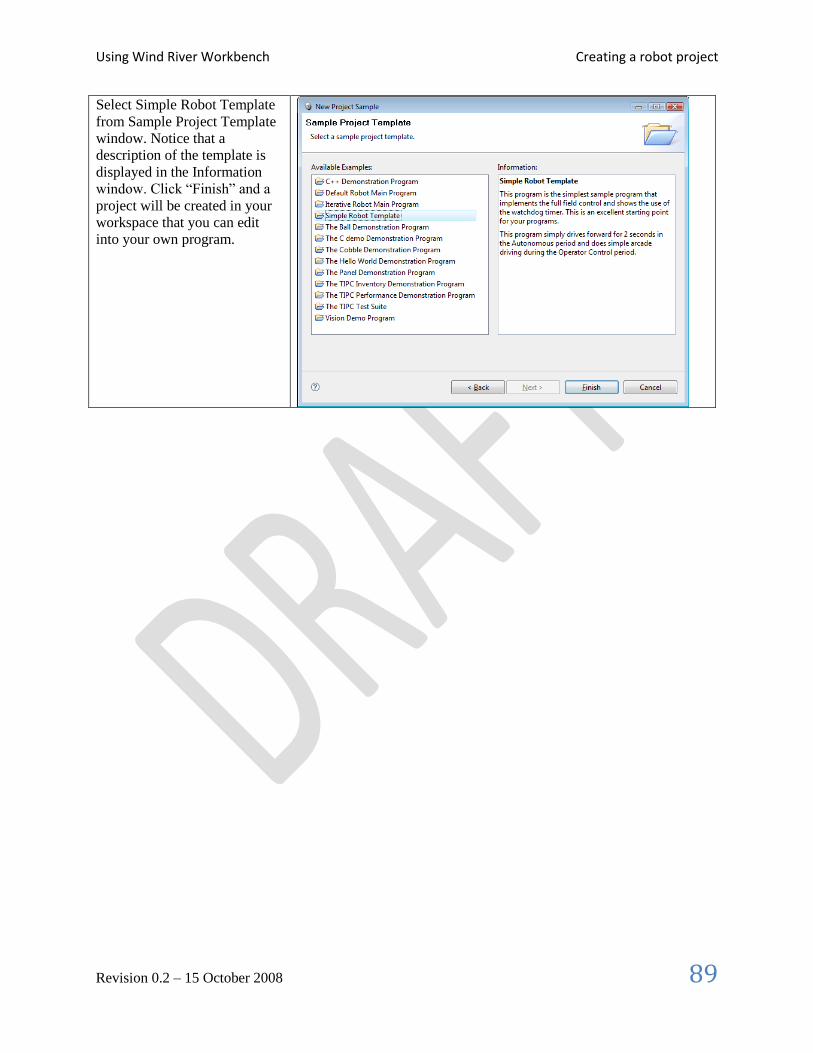
Using Wind River Workbench Creating a robot project
Revision 0.2 – 15 October 2008 89
Select Simple Robot Template
from Sample Project Template
window. Notice that a
description of the template is
displayed in the Information
window. Click “Finish” and a
project will be created in your
workspace that you can edit
into your own program.

Using Wind River Workbench Building your project
Revision 0.2 – 15 October 2008 90
Building your project The project is built by right-clicking on the project name in the Project Explorer window and select
“Build project” or “Rebuild project” from the popup context menu. This will cause Workbench to
compile and link the project files into a .OUT executable file that may be either deployed or downloaded
to the cRIO.
Another way of building the project is to automatic rebuild feature of Workbench. Whenever a file in the
project is saved, a build will automatically be started to keep the project up to date. To enable this feature:
Select “Window”, then “Preferences”. In the Preferences panel, expand “General”, then “Workspace” and
check the “Build automatically” option. Files can quickly be saved after editing by using the shortcut,
Ctrl-S.

Using Wind River Workbench Downloading the project to the cRIO
Revision 0.2 – 15 October 2008 91
Downloading the project to the cRIO There are two ways of getting your project into the cRIO:
1. Using a Run/Debug Configuration in Workbench. This loads the program into the cRIO RAM
memory and allows it to run either with or without the debugger. When the robot is rebooted, the
program will no longer be in memory.
2. Deploy the program through the FIRST Downloader option in Workbench. In this case the
program will be written to the flash disk inside the cRIO and will run whenever it is rebooted
until it is Undeployed (deleted from flash). This is the option to take a finished program and make
it available for a match – so that it will run without an attached computer to always load it.
The deployed code only runs on reboot - it's the LV Runtime that goes through a list of programs to run
on startup. Those programs are loaded from the flash disk on the cRIO. It actually is always trying to load
the deployed program, which has a fixed name regardless of what you call it. But when the program is
UnDeployed (deleted), it fails silently to load the file.
When you are using the debugger, the program is loaded into RAM and runs from there.
If you have the program starting from disk and running in the background, then you launch it again for
debugging (or a different program) things get very confusing.
It is also sometimes advantageous to reboot between debugging sessions. Sometimes things don't get
completely cleaned up even if you try to unload the program. We're working on that. You can reboot
remotely by right-clicking on the connection in the "Remote Systems" tab in Workbench and selecting
"Reset target" (or something like that). It will reboot it - takes about 15 sec.
The steps for debugging if there is already a programmed deployed:
1. Undeploy
2. Reboot the cRIO
3. Do debug in Workbench
To deploy a program to the cRIO:
1) Download
2) Reboot the cRIO

Using Wind River Workbench Debugging your robot program
Revision 0.2 – 15 October 2008 92
Debugging your robot program You can monitor, control and manipulate processes using the debugger. This section will describe how to
set up a debug session on a robot control program for the cRIO. The Wind River Workbench User’s
Guide contains the complete documentation on how to use the debugger.
To run a program that derives from one of the WPILib robot base classes, such as SimpleRobot.cpp, or
IterativeRobot.cpp, a macro called START_ROBOT_CLASS is used that starts one task that does nothing
except kick off the robot task. This is done so that the correct run options can be set. See SimpleDemo or
IterativeDemo for examples. This makes it necessary to set up debug to attach to the spawned task instead
of the first task started.
To start a debug session, connect to the target and click on the bug icon or right click the project and
select “Debug Kernal Task…” The Debug dialog is displayed.
Figure 7: Setting the entry point on a Debug Configuration for a robot program.
Select as the entry point the function FRC_UserProgram_StartupLibraryInit. On the debug options tab,
select “Break on Entry” and “Automatically attach spawned Kernel Tasks”. This tells the debugger to
stop at the first instruction, and to make the spawned task (your robot task) available to debug.

Using Wind River Workbench Debugging your robot program
Revision 0.2 – 15 October 2008 93
Figure 8: Setting the “Automatically attach spawned Kernel Tasks” option ensures that you will be able to debug the entire program including any tasks that it creates. The WPI Robotics Library automatically creates your program in a new task when it starts.
The other tabs can normally be left at default settings.
When the “Debug” button is selected, several things happen. Your Workbench display changes to the
Debug Perspective, which has views for debug, breakpoints and variables along the right side. The task is
kicked off and stops in the first instruction, in FRC_UserProgram_StartupLibraryInit. At this
point make sure that a breakpoint is set in your user program. Select the “Resume” icon (the green arrow)
to continue until the first breakpoint is reached.

Using Wind River Workbench Debugging your robot program
Revision 0.2 – 15 October 2008 94
The Debug view shows all processes and threads running under the debugger. Selecting the stack frame
will show the current instruction pointer and source code (if available) for the process selected. When
your breakpoint is reached, make sure your program is selected in the task list, and your source code is
displayed with a program pointer. You can continue through your code using “Resume”, “Step Into”,
“Step Over” and “Step Return”. If you see assembly code displayed this is because you have gone into a
lower level of code where the source is not available. A “Step Return” will bring you back up a level.
To stop debugging, you may disconnect or terminate the process. Disconnecting detaches the debugger
but leaves the process running in its current state. Terminating the process kills it on the target.
Troubleshooting:
Source code displayed is out of sync with cursor when debugging: The source has changed since it
was loaded onto the cRIO. Rebuild the project and make sure included projects are up to date.
Robot program not visible in the Debug View: Make sure that “Automatically attach spawned Kernel
Tasks” option is set. The first stop happens before your program is started. It will appear after you
“Resume.”

C++ Tips Debugging your robot program
Revision 0.2 – 15 October 2008 95
C++ Tips

Creating an application in WorkBench Debugging your robot program
Revision 0.2 – 15 October 2008 96
Creating an application in WorkBench

Using C with the WPI Robotics Library Debugging your robot program
Revision 0.2 – 15 October 2008 97
Using C with the WPI Robotics Library You can also write C programs with the WPI Robotics Library using a set of C functions that map on top
of the C++ classes and methods. To write C code:
You need to create .cpp (C++ files) rather than .C files because the C wrapper functions take
advantage of overloaded functions. This means that there are a number of functions that have
the same name, but different argument lists. This increases the compatibility with the C++
programming interfaces and will make transition to C++ much easier if you choose to do that.
Specify port and/or slot (module) numbers in most of the functions. Behind the scenes, the
functions are allocating C++ objects that correspond to the functions that you are using. This
serves two purposes: it ensures that you are not using a particular port for two purposes
accidently since the C++ underlying functions track “reservations” and makes the code very
similar to previous years where the port numbers were on each call.
You will find that there are a few C++ higher level code options that do not exist in C, it is a lower level
interface to the hardware connected to the cRIO and the driver station.
Example of a C program
The following C program demonstrates driving the robot for 2 seconds forward in Autonomous and in
arcade mode for the Operator Control period. Notice that constants define the port numbers used in the
program. This is a good practice and should be used for C programs.

Using C with the WPI Robotics Library Debugging your robot program
Revision 0.2 – 15 October 2008 98
#include "WPILib.h"
#include "SimpleCRobot.h"
static const UINT32 LEFT_MOTOR_PORT = 1;
static const UINT32 RIGHT_MOTOR_PORT = 2;
static const UINT32 JOYSTICK_PORT = 1;
void Initialize(void)
{
CreateRobotDrive(LEFT_MOTOR_PORT, RIGHT_MOTOR_PORT);
SetWatchdogExpiration(100);
}
void Autonomous(void)
{
SetWatchdogEnabled(false);
Drive(0.5, 0.0);
Wait(2000);
Drive(0.0, 0.0);
}
void OperatorControl(void)
{
SetWatchdogEnabled(true);
while (IsOperatorControl())
{
WatchdogFeed();
ArcadeDrive(JOYSTICK_PORT);
}
}
START_ROBOT_CLASS(SimpleCRobot);

Contributing to the WPI Robotics Library Debugging your robot program
Revision 0.2 – 15 October 2008 99
Contributing to the WPI Robotics Library

Glossary Debugging your robot program
Revision 0.2 – 15 October 2008 100
Glossary Concurrency
cRIO
deadlock
quadrature encoder
semaphore
task
VxWorks

Index Debugging your robot program
Revision 0.2 – 15 October 2008 101
Index accelerometer, 25
Compass, 27
counter, 29
digital I/O, 22
digital input, 23
digital output, 24
gyro, 26
IterativeRobot, 16, 18
objects, 10
RobotBase, 16, 19
sensors, 21
SimpleRobot, 9, 16, 17
ultrasonic rangefinder, 28
watchdog timer, 13, 20