Embed Size (px)
Citation preview
Chairman John Donovan AT&T First Vice Chairman Nick Adamo Cisco Systems Second Vice Chairman Thomas Sawanobori Verizon Treasurer Joseph Hanley Telephone and Data Systems President & Chief Executive Officer Susan M. Miller ATIS Vice President of Finance & Operations William J. Klein ATIS
1200 G Street, NW P: 202-628-6380 Suite 500 F: 202-393-5453 Washington, DC 20005 W: www.atis.org
Standards that Drive the Business of Communications
August 12, 2011
Via Email
Jeffrey Goldthorp
Chief, Communications Systems Analysis Division
Public Safety and Homeland Security Bureau
Federal Communications Commission
445 12th Street, SW
Washington, DC 20554
Re: ATIS NRSC 9-1-1 CAMA Trunk Throughput Optimization Analysis, ATIS-
0100034
Dear Jeff:
Enclosed herewith is the NRSC 9-1-1 CAMA Trunk Throughput Optimization Analysis
(ATIS-0100034) that was developed by the Alliance for Telecommunications Industry
Solutions’ (ATIS) Network Reliability Steering Committee (NRSC). This document,
which will be made available free of charge to the industry from the NRSC website at
www.atis.org/nrsc, will be discussed during next week’s NRSC meeting in Snoqualmie,
WA.
This analysis reflects a significant amount of work by NRSC members and invited
subject matter experts. Since the initiation of the project in May, more than twenty-one
separate NRSC meetings were held to progress the work, in addition to the significant
work undertaken by individual members outside of these meetings. The document also
reflects input received from GENBAND. However, it should be noted that, because
GENBAND is not currently a member of the NRSC, it was not able to participate in the
approval of the document and has not reviewed the final document.
Finally, it should be noted that the document does not reflect the testing undertaken by
the industry regarding the Alcatel-Lucent 5ESS 9-1-1 selective routers. This testing did
occur as agreed and the laboratory results indicated that these selective routers did not
present the same risks of focused overloads of E9-1-1 systems during periods of heavy
call volume.
If there are any questions regarding this matter, please do not hesitate to contact me.
Sincerely,
Thomas Goode
General Counsel
cc: John Healy, Associate Division Chief, Cybersecurity and Communications
Reliability Division

ATIS-0100034
ATIS Standard on -
NRSC 9-1-1 CAMA TRUNK THROUGHPUT OPTIMIZATION ANALYSIS
ATIS is the leading technical planning and standards development organization committed to the rapid development of global, market-driven standards for the information, entertainment and communications industry. More than 200 companies actively formulate standards in ATIS’ Committees, covering issues including: IPTV, Cloud Services, Energy Efficiency, IP-Based and Wireless Technologies, Quality of Service, Billing and Operational Support, Emergency Services, Architectural Platforms and Emerging Networks. In addition, numerous Incubators, Focus and Exploratory Groups address evolving industry priorities including Smart Grid, Machine-to-Machine, Networked Car, IP Downloadable Security, Policy Management and Network Optimization.
ATIS is the North American Organizational Partner for the 3rd Generation Partnership Project (3GPP), a member and major U.S. contributor to the International Telecommunication Union (ITU) Radio and Telecommunications’ Sectors, and a member of the Inter-American Telecommunication Commission (CITEL). ATIS is accredited by the American National Standards Institute (ANSI). For more information, please visit < http://www.atis.org >.
Notice of Disclaimer & Limitation of Liability The information provided in this document is directed solely to professionals who have the appropriate degree of experience to understand and interpret its contents in accordance with generally accepted engineering or other professional standards and applicable regulations. No recommendation as to products or vendors is made or should be implied. NO REPRESENTATION OR WARRANTY IS MADE THAT THE INFORMATION IS TECHNICALLY ACCURATE OR SUFFICIENT OR CONFORMS TO ANY STATUTE, GOVERNMENTAL RULE OR REGULATION, AND FURTHER, NO REPRESENTATION OR WARRANTY IS MADE OF MERCHANTABILITY OR FITNESS FOR ANY PARTICULAR PURPOSE OR AGAINST INFRINGEMENT OF INTELLECTUAL PROPERTY RIGHTS. ATIS SHALL NOT BE LIABLE, BEYOND THE AMOUNT OF ANY SUM RECEIVED IN PAYMENT BY ATIS FOR THIS DOCUMENT, WITH RESPECT TO ANY CLAIM, AND IN NO EVENT SHALL ATIS BE LIABLE FOR LOST PROFITS OR OTHER INCIDENTAL OR CONSEQUENTIAL DAMAGES. ATIS EXPRESSLY ADVISES ANY AND ALL USE OF OR RELIANCE UPON THIS INFORMATION PROVIDED IN THIS DOCUMENT IS AT THE RISK OF THE USER.
NOTE - The user’s attention is called to the possibility that compliance with this standard may require use of an invention covered by patent rights. By publication of this standard, no position is taken with respect to whether use of an invention covered by patent rights will be required, and if any such use is required no position is taken regarding the validity of this claim or any patent rights in connection therewith.
ATIS-0100034, NRSC 9-1-1 CAMA Trunk Throughput Optimization Analysis
Is an ATIS Standard developed by the ATIS Network Reliability Steering Committee (NRSC).
Published by
Alliance for Telecommunications Industry Solutions 1200 G Street, NW, Suite 500 Washington, DC 20005 Copyright © 2011 by Alliance for Telecommunications Industry Solutions All rights reserved. No part of this publication may be reproduced in any form, in an electronic retrieval system or otherwise, without the prior written permission of the publisher. For information contact ATIS at 202.628.6380. ATIS is online at < http://www.atis.org >. Printed in the United States of America.
ATIS-0100034
ATIS Standard on
NRSC 9-1-1 CAMA TRUNK THROUGHPUT OPTIMIZATION ANALYSIS
Alliance for Telecommunications Industry Solutions
Approved August 2011
Abstract
This paper addresses the Alliance for Telecommunications Industry Solutions' (ATIS) Network Reliability Steering Committee’s (NRSC’s) review of Centralized Automatic Message Accounting (CAMA) trunks used in some 9-1-1 configurations. As part of this review, incidents of high call volume and the current 9-1-1 architecture were reviewed. This report provides the industry with recommendations to assist in mitigating these types of incidents in the future; as well as, to maximize 9-1-1 call throughput to PSAPs during high call volume conditions.
ATIS-0100034
ii
FOREWORD The Alliance for Telecommunication Industry Solutions (ATIS) serves the public through improved understanding between providers, customers, and manufacturers. The ATIS Network Reliability Steering Committee (NRSC) was formed at the request of the first Network Reliability Council (NRC-1) to monitor network reliability. NRSC is a consensus-based industry committee that analyzes the communications industry's reporting of network outages, makes recommendations aimed at improving network reliability, distributes the results of its findings to industry, and, where applicable, refers matters to appropriate industry forums for further resolution. The NRSC also reviews regulatory developments affecting network reliability and submits consensus-developed comments on matters of common interest to NRSC members.
The mandatory requirements are designated by the word shall and recommendations by the word should. Where both a mandatory requirement and a recommendation are specified for the same criterion, the recommendation represents a goal currently identifiable as having distinct compatibility or performance advantages. The word may denotes a optional capability that could augment the standard. The standard is fully functional without the incorporation of this optional capability.
Suggestions for improvement of this document are welcome. They should be sent to the Alliance for Telecommunications Industry Solutions, NRSC, 1200 G Street NW, Suite 500, Washington, DC 20005.
CAMA Trunk Project Schedule The NRSC, during the preparation of this paper, held 21 subject matter expert or technical writing sessions bringing together industry experts in 9-1-1 Selective Router network design and network operation from no less than seven major communication providers and Telcordia. The dates of the sessions covered the period from May to August 2011. Below are the individual dates of the sessions:
05/19/2011, 05/26/2011, 06/02/2011, 06/09/2011, 06/14/2011, 06/16/2011, 06/21/2011, 06/23/2011, 06/28/2011, 06/30/2011, 07/05/2011, 07/07/2011, 07/12/2011, 07/14/2011, 07/19/2011, 07/21/2011, 07/26/2011, 07/27/2011, 07/28/2011, 08/02/2011, and 08/04/2011.
Participating Companies AT&T
CenturyLink
Cox Communications
T-Mobile USA
Telcordia
Verizon
Verizon Wireless

ATIS-0100034
iii
TABLE OF CONTENTS ISSUE OVERVIEW ............................................................................................................................................................. 1
CALL FLOW OVERVIEW: 9‐1‐1 CALL FLOW OVER MULTI‐FREQUENCY (MF) CENTRALIZED AUTOMATIC MESSAGE ACCOUNTING (CAMA) PUBLIC SAFETY ANSWERING POINT (PSAP) TRUNKS ...................................................................... 2
ARCHITECTURAL REVIEW ................................................................................................................................................. 3
INITIAL ANALYSIS ............................................................................................................................................................. 4
TECHNICAL SPECIFICATION REVIEW ................................................................................................................................. 4
TRUNK SIZING .................................................................................................................................................................. 5
TRUNK BUSY PERCENTAGE CONFIGURATION ................................................................................................................... 6
PROS/CONS WITH ALLOWING 100% OF MEMBERS OF A TRUNK GROUP TO BE MADE BUSY BY THE NETWORK .............................................. 6 PROS/CONS WITH NOT ALLOWING 100% OF MEMBERS OF A TRUNK GROUP TO BE MADE BUSY BY THE NETWORK ........................................ 7
TRUNK OVERFLOW ROUTE ............................................................................................................................................... 7
TRUNK ALARM RECOMMENDATION ................................................................................................................................ 8
ROOT CAUSE ANALYSIS .................................................................................................................................................... 9
STEPS TAKEN TO PREVENT REOCCURRENCE ................................................................................................................... 11
NRSC RECOMMENDATIONS FOR 9‐1‐1 SELECTIVE ROUTER SERVICE PROVIDER MITIGATION ........................................... 11
NRSC RECOMMENDATIONS FOR CHANGES TO PSAP OPERATIONS AND SOPS ................................................................. 12
OTHER CONSIDERATIONS .............................................................................................................................................. 13
CONCLUSION ................................................................................................................................................................. 14
REFERENCES .................................................................................................................................................................. 16
DEFINITIONS .................................................................................................................................................................. 17
TERM ....................................................................................................................................................................................... 17 DEFINITION ............................................................................................................................................................................... 17
ABBREVIATIONS AND ACRONYMS ................................................................................................................................. 18
APPENDIX A – THE SIGNAL STATE DIAGRAM OF PSAP TRUNK ......................................................................................... 19
APPENDIX B – THE LADDER DIAGRAM OF A STANDARD CALL TO ACTIVE STATE .............................................................. 20
APPENDIX C – THE DISCONNECT OF A CALL, AND THE NO‐WINK CONDITION .................................................................. 22
APPENDIX D – THE DISCONNECT OF A CALL BEFORE ANSWER (ABANDONED CALL, AND THE NO‐WINK CONDITION) ....... 24
APPENDIX E – GENBAND DMS‐100 E911 LOG MESSAGES ................................................................................................ 26
APPENDIX F ‐ LAB TEST SUMMARY ................................................................................................................................. 27
TABLE OF FIGURES FIGURE 1: NETWORK ARCHITECTURE OVERVIEW .................................................................................................................................... 3 FIGURE 2: SR SIGNALING STATES ....................................................................................................................................................... 19
ATIS STANDARD ATIS-0100034
ATIS Standard on –
NRSC 9-1-1 CAMA Trunk Throughput Optimization Analysis
1
ISSUE OVERVIEW Service Providers and the Federal Communications Commission (FCC) have observed a 9-1-1 service-affecting issue that may occur during a sustained Mass Calling Event to 9-1-1 that causes a Focused Overload of the E9-1-1 system. The NRSC will reference Telcordia Technologies’ definition of a Focused Overload:
A focused overload is generally directed toward a particular location and may result from media stimulation (news programs, advertising, call-in contests, telethons) or events that cause mass calling to government or public-service agencies, weather bureaus, or public utilities. Without the application of appropriate network controls, the effects of these types of overloads could spread throughout the network. Focused overloads are normally managed using code controls or, if anticipated, trunk-limited or choke networks.1
For purposes of this report, Mass Calling Events or Focused Overloads will be hereafter referred to as periods of heavy call volume to 9-1-1.
Recently, the industry has observed some heavy call volumes that can result in Wink Failures of Selective Router (SR) to Public Safety Answering Point (PSAP) Centralized Automatic Message Accounting (CAMA)2 trunks. These trunks transmit the caller’s Automatic Number Identification (ANI) using Multi-Frequency (MF) digits based upon CAMA signaling standards. CAMA trunk technology, which was originally designed to provide a method for delivering the calling (originating) number from End Office to Toll Office, has widespread support across many platforms within the industry and has proven to be a highly reliable 9-1-1 standard. In the 9-1-1 context, the ANI digits that identify the 9-1-1 caller are relayed across the CAMA trunk to the PSAP. CAMA trunks utilize in-band signaling for call setup and, if the call setup is not successful due to a signaling failure, the SR can remove the CAMA trunk from service.
Wink Failures can occur during heavy call volume events to 9-1-1 PSAPs and result in a 9-1-1 SR removing PSAP trunks from service during call setup. These Wink Failures occur when a SR presents a new call to the PSAP over an idle trunk and the SR does not receive a supervisory OFF-HOOK Wink to signify the Customer Premise Equipment’s (CPE’s) ability to receive the ANI digits using MF Signaling Tones. This can happen if the time needed for the 9-1-1 CPE to both recognize an ON-HOOK condition from the SR and be ready for the next 9-1-1 call exceeds the duration of the ON-HOOK condition (i.e., from the time that a caller disconnects to when a new 9-1-1 call is sent to the CPE from the SR). In this case, if the 9-1-1 CPE does not recognize the call as a new call, then the CPE may not provide a Wink to the re-seizure of the trunk. As a result, the 9-1-1 SR would count one No-Wink condition for this trunk. During normal operation, if the 9-1-1 SR detected a No-Wink condition on a trunk, the call would
1 Telcordia Technologies, Telcordia Notes on the Networks (SR-2275, Issue 4, October 2000), page 10-6.
2 GR-350 requirements do not specify the use of CAMA trunks -- as an example, GENBAND SR uses Line Digital Trunks (LDT), which is not based on their CAMA software. NENA sometimes considers these as CAMA-Like or Enhanced MF trunks.
ATIS-0100034
2
normally be offered to the next available trunk in a round-robin fashion. This practice would avoid two consecutive call setup failures due to No-Wink on the same trunk.
Double wink failures occur when a second No Wink condition occurs. For example, if all other trunks remain busy, as is often the case during a heavy call volume event, a call previously sent to a trunk that had a No Wink Failure could again be offered to the same trunk. If this second offering results in another No-Wink condition, the 9-1-1 SR will, per standard design, “busy out” that trunk (i.e., take the trunk out of service and place it in an out of service state). With the removal of individual trunks due to these double wink failures, there is a reduction of call handling capacity within the specific group of trunks serving the PSAP. In the case that a heavy call volume event persists, all trunks within the affected trunk group could potentially be taken out of service. This condition has been observed by various 9-1-1 Service Providers, with the most recent condition being observed during a heavy call volume event related to a blizzard in January 2011.
CALL FLOW OVERVIEW: 9-1-1 CALL FLOW OVER MULTI-FREQUENCY (MF) CENTRALIZED AUTOMATIC MESSAGE ACCOUNTING (CAMA) PUBLIC SAFETY ANSWERING POINT (PSAP) TRUNKS The 9-1-1 call flow process associated with a “Wink Failure” condition over an MF CAMA trunk can be generally stated to operate in the following manner:
1. A 9-1-1 call is received at the Service Provider’s SR and -- based on the received Automatic Number Identification (ANI), typically the Calling Party Number -- the SR determines the appropriate PSAP to receive the call.
2. The SR then looks for an available PSAP trunk in the trunk group connected to the target PSAP.
3. Once the SR finds an available trunk, the provider’s SR sends a signal to the PSAP Customer Premises Equipment (CPE). If working properly, the CPE will respond with a short duration signal (“wink”) within a certain time frame signifying its ability to receive the calling party’s telephone number.
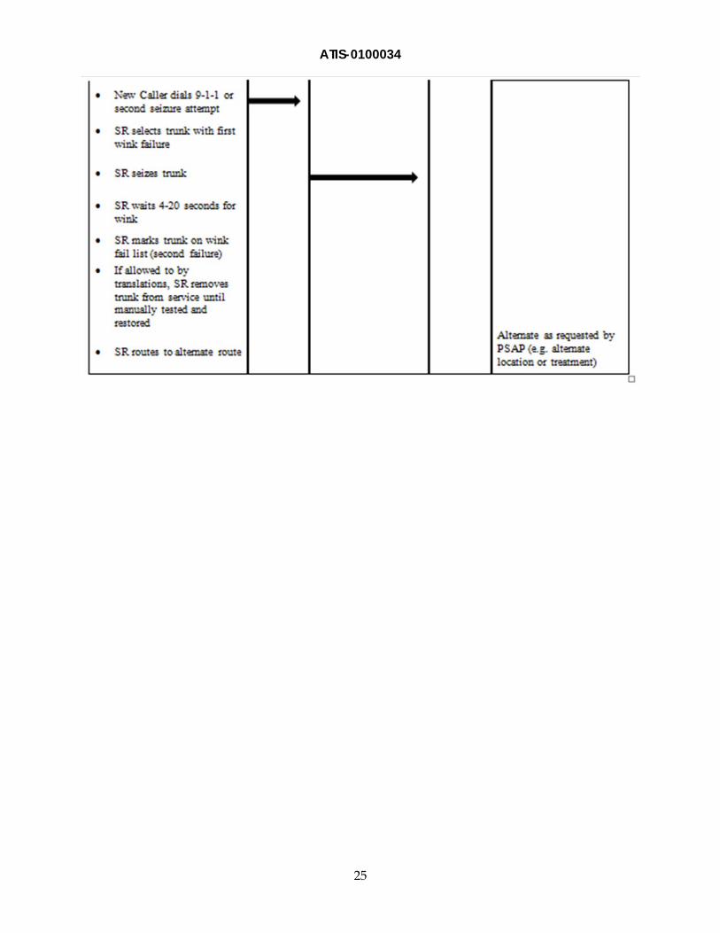
4. If no signal is sent back to the 9-1-1 SR within the specified maximum time period (e.g., 4 seconds), the SR releases the trunk and searches for another available trunk connected to the target PSAP to initiate a second attempt to route the call. 3
5. If the CPE “winks” back within the wink time interval to the second attempt, the call completes. If the CPE does not signal back in the required timeframe, the call is routed to treatment (60 or 120 interruptions per minute busy tone) if no alternate route is associated with the trunk group. If the PSAP trunk group has an alternate route, if allowed by translations, the SR will start the call process over attempting to seize a member in the overflow PSAP trunk group.4
3 In periods of high call volume, or when all other trunks to the PSAP are active with another call or out of service, the only available member may be the trunk just released, and the second attempt may re-seize the same trunk.
4 The 5ESS type SR does not alternate route a call after two successive wink failures but the GENBAND DMS-100 has translations capability to do so, however, Industry is working to re-verify this fact with lab testing.
ATIS-0100034
3
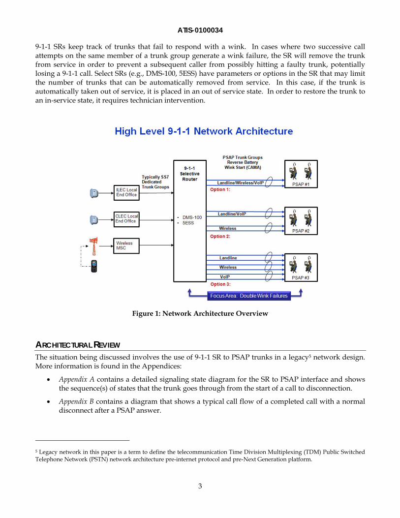
9-1-1 SRs keep track of trunks that fail to respond with a wink. In cases where two successive call attempts on the same member of a trunk group generate a wink failure, the SR will remove the trunk from service in order to prevent a subsequent caller from possibly hitting a faulty trunk, potentially losing a 9-1-1 call. Select SRs (e.g., DMS-100, 5ESS) have parameters or options in the SR that may limit the number of trunks that can be automatically removed from service. In this case, if the trunk is automatically taken out of service, it is placed in an out of service state. In order to restore the trunk to an in-service state, it requires technician intervention.
Figure 1: Network Architecture Overview
ARCHITECTURAL REVIEW The situation being discussed involves the use of 9-1-1 SR to PSAP trunks in a legacy5 network design. More information is found in the Appendices:
Appendix A contains a detailed signaling state diagram for the SR to PSAP interface and shows the sequence(s) of states that the trunk goes through from the start of a call to disconnection.
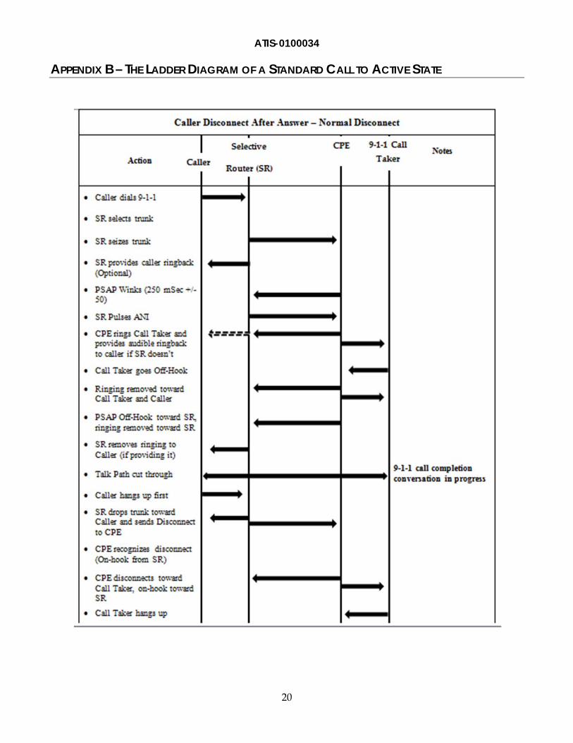
Appendix B contains a diagram that shows a typical call flow of a completed call with a normal disconnect after a PSAP answer.
5 Legacy network in this paper is a term to define the telecommunication Time Division Multiplexing (TDM) Public Switched Telephone Network (PSTN) network architecture pre-internet protocol and pre-Next Generation platform.
ATIS-0100034
4
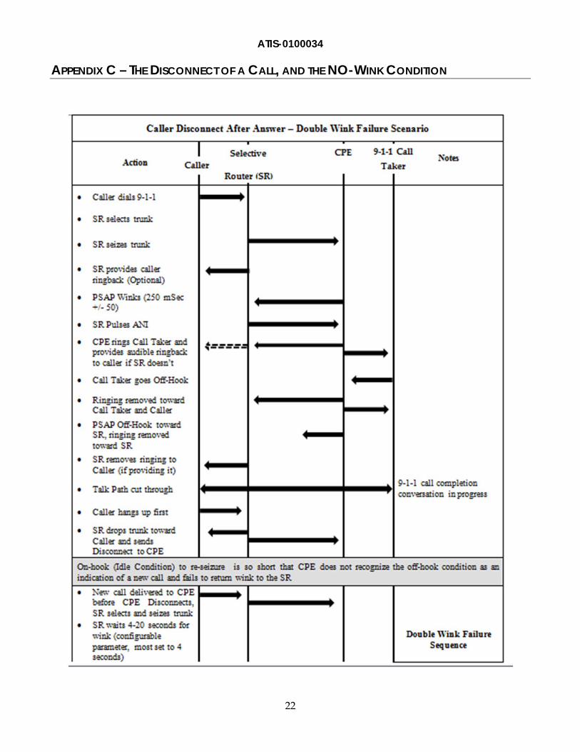
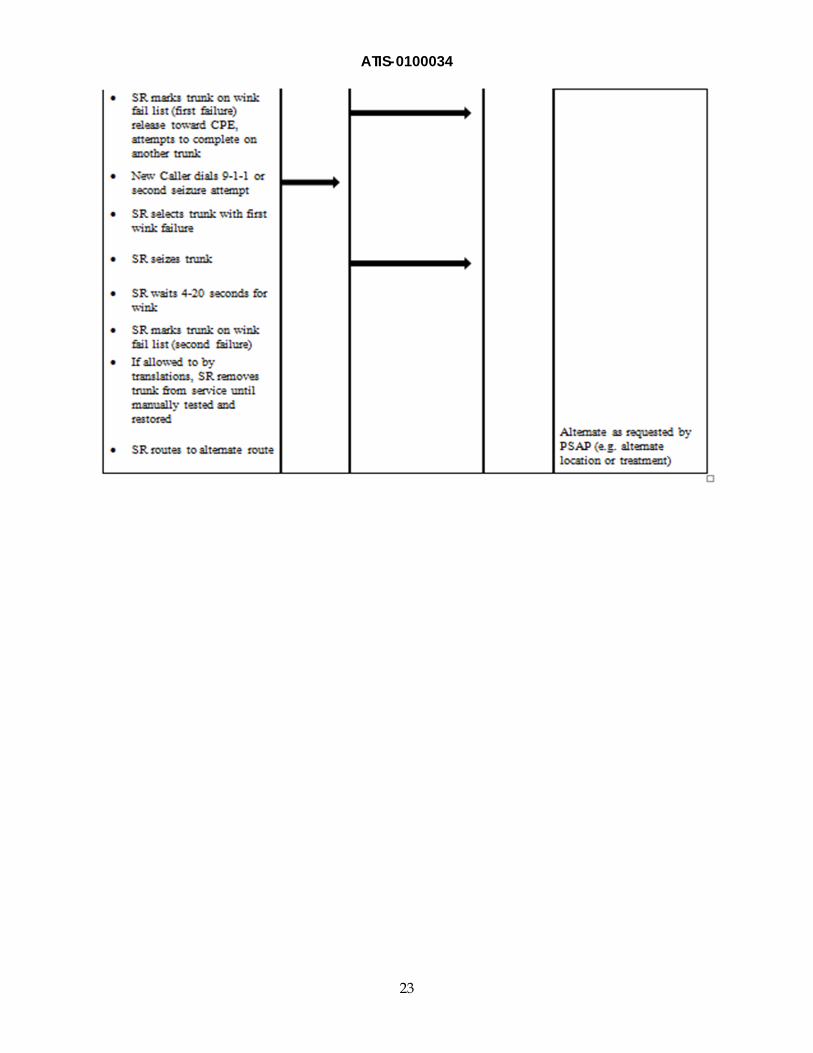
Appendix C contains a diagram that shows a condition where the SR is providing a call attempt to the CPE and experiences a No-Wink condition following a caller disconnect after a PSAP answer on a completed call, resulting in a double wink failure scenario.
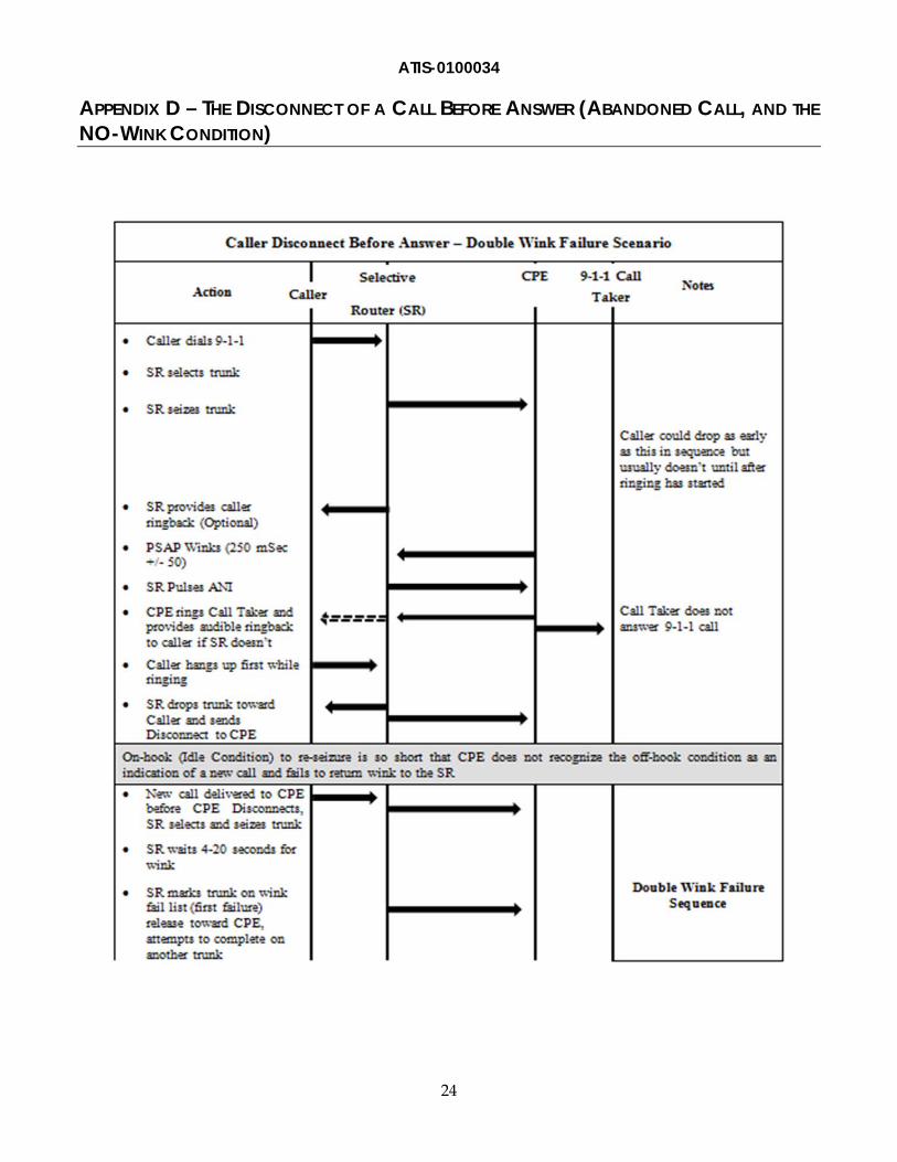
Appendix D contains a diagram that shows a condition where the SR is providing a call attempt to the CPE and experiences a No-Wink condition following a caller disconnect during call setup (abandoned call), resulting in a double wink failure scenario.
INITIAL ANALYSIS Initial discussions by industry 9-1-1 subject matter experts occurred to review laboratory test results from a Service Provider, which served to identify the scope of the double wink failure as defined by the team. The issue defined by the NRSC was outlined as the time needed for the 9-1-1 CPE to recognize an ON-HOOK condition from the SR and be ready for the next 9-1-1 call, which can exceed the duration of the ON-HOOK condition between a caller disconnect and a new call being offered to the CPE by certain SRs . This establishes a condition where the offering of a new call to a PSAP could experience a No-Wink condition from the CPE. Upon two successive No-Wink conditions, certain legacy 9-1-1 SRs will remove the trunk from service. This would result in fewer trunks remaining to receive and handle additional calls. There is a potential that all the trunks can be taken out of service due to a No-Wink condition. In this case, all incoming 9-1-1 calls will be routed to treatment if the PSAP has not requested an overflow route to another PSAP, administrative line, or other location to receive the call.
TECHNICAL SPECIFICATION REVIEW An analysis of the situation has determined that this could be a timing situation between the SR and the CPE. In order to determine if there is a timing problem, it must be determined if there are technical specifications that demonstrate timing issues for this type of circuit.
There are four standards that define the SR to PSAP interface:
Telcordia GR-350-CORE, E9-1-1 Public Safety Answering Point Interface Between a 1/1AESS Switch and Customer Premises Equipment.6
Telcordia GR-2953-CORE, Enhanced MF Signaling: E9-1-1 Tandem to PSAP Interface.6
NENA 03-002, NENA Standard for the Implementation of Enhanced MF Signaling, E9-1-1 Tandem to PSAP.7
ATIS-0600414.1998 (R2007), Network to Customer Installation Interfaces – Enhanced 9-1-1 Analog Voice grade PSAP Access Using Loop Reverse – Battery Signaling.8
6 Telcordia documents are available from Industry Direct Sales, Telcordia, 8 Corporate Place, PYA 3A-184, Piscataway, NJ, 08854-4156, or < http://telecom-info.telcordia.com >.
7 This document is available from the National Emergency Number Association. < http://www.nena.org/standards/informational >
8 This document is available from the Alliance for Telecommunications Industry Solutions (ATIS), 1200 G Street N.W., Suite 500, Washington, DC 20005. < https://www.atis.org/docstore/default.aspx >

ATIS-0100034
5
The NRSC’s review of these documents shows that the first three (GR-350, GR-2953, NENA 03-002) have no reference to timing intervals between calls. The ATIS document [ATIS-0600414.1998 (R2007)]9 specifies that when the disconnect is from the caller direction the network (SR) shall apply an on hook signal toward the CPE for at least 700 mSec.10 Therefore, some of the standards and specifications on how to handle disconnects need to be further defined by the industry to clarify inter-call timing. In addition, since the circuits use “loop start, reverse-battery signaling,” this report suggests that other industry standards may provide additional information with regard to this interface. In particular, consideration should be given to those standards that relate to “guard” timing, a timer that specifies the amount of time for which a trunk will be unavailable for seizure following a release, to allow the trunk to clear before re-seizing.
TRUNK SIZING It is not the position of the NRSC to recommend trunk sizing for 9-1-1 trunk capacity, believing this should be left to the 9-1-1 providers and system users based on NENA developed recommendations. The focus of this paper is to provide recommendations to the industry on mitigating the wink failures that may occur due to heavy call volumes, and to maximize throughput and call delivery on whatever number of trunks are in use. However, the NRSC makes the following considerations regarding trunk sizing:
A review of P.01 Grade of Service: 9-1-1 network sizing has always been a balance between having a sufficient number of circuits to carry traffic during normal call volumes and not installing so much capacity that it makes the network excessively costly, or places too many calls into a queue that the PSAP cannot process. The rule of thumb is to design each network component to meet a P.01 Grade of Service, in which network components, number of positions, number of call takers, and other items in the system are sufficient so that the resource is able to handle all the offered load with an exception of up to 1% of the load during the average busy hour on an average busy day (i.e., only 1 call out of a theoretical 100 attempts would get a busy signal). The sizing is described in NENA 03-50611, and would apply to trunk group quantities between network elements such as:
o End office to the SR.
o SR to the PSAP.
o SR to SR.
o Wireless MSC to SR.12
9 See ATIS-0600414.1998 (R2007), section 4.8.1.1.
10 Many SR implementations were provisioned to Telcordia specifications that pre-dated the ATIS specifications. The 700mSec requirement does not appear in the Telcordia specifications. Also, to be accurate, it must be noted that the DMS-100 SR requirements were developed by Nortel prior to GENBAND involvement in the DMS-100 SR.
11 NENA 03-506, NENA E9-1-1 Voice Circuit Requirements -- Providing a P.01 Grade of Service Technical Information Document (TID), Issue 1.
12 Wireless Carriers may advise the PSAP of the optimal amount of trunks for P.01 Grade of Service during the wireless traffic planning; however, the PSAP determines the number of calls they will accept from each wireless carrier, which has a direct impact on trunk sizing requirements between the wireless MSC and the PSAP Selective Router.
ATIS-0100034
6
Separate trunk groups for wireline, wireless, and VoIP: The industry has not reached consensus on this issue. Many experts believe the separation of wireless and wireline traffic aids in call management, capturing call statistics, and allowing separate overflow routes for the different traffic classes. In particular, with a separate PSAP trunk group for wireless, if there is a spike in wireless calls, conceptually there would be trunks still available to accommodate wireline calls in the trunk group dedicated to the wireline service type. However, others believe that separate groups reduce the efficiency of the circuits, add costs to the 9-1-1 network, and have different busy periods, so one service is less likely to block calls from the other service when combined.
Capacity management and sizing review: It is recommended that 9-1-1 system providers periodically review trunk group sizing requirements as necessary to validate that trunk group sizes are appropriate for the traffic offered (NENA 03-006).13 This step is often necessary when PSAPs combine or modify territory coverage. However, it is very important not to over-size the trunk groups. Over-sizing is when there are more trunks than are necessary to carry the traffic, while call taker staffing is determined separately. Proper sizing allows normal traffic to be handled, but also allows calls during high call volume periods to overflow to an alternate/backup PSAP, instead of experiencing a “ring-no-answer” (until a call taker is available to answer the call) in a PSAP that is over-trunked.
TRUNK BUSY PERCENTAGE CONFIGURATION Trunk Busy Percentage Configuration relates to how many trunks the SR is allowed to remove from service on its own. Different legacy SR types have different methodologies and limits, as well as different methods that it takes to restore a trunk to service. Some legacy SRs have the ability to set a maximum percentage of members that may be removed from service. The next two sections of the paper discuss the Pros and Cons of allowing 100% of trunk members to be made busy by the SR versus implementing a strategy of not allowing 100% of the trunk members to be made busy by the SR.
Pros/Cons with allowing 100% of Members of a Trunk Group to be Made Busy by the Network Pro: During CPE failure, cable cut, or other true outage conditions, this lets overflow calls route to an alternative location if provisioned capable of meeting the caller’s needs.14
Pro: This could speed up identification and resolution of the problem. The automatic nature of the SR can make the circuits busy much quicker than it would take for a technician to receive and analyze trouble reports (often during a period when there are a high volume of trouble cases), and to contact and verify the problem with the Public Safety Agency. The network may therefore more quickly recognize the problem, and use standard practices to prevent calls from failing, than it would take a technician to do so.
Pro: Prevents call failures in instances where a PSAP may be small, and receive very little traffic in instances where they are unaware of a CPE or network failure. Having the trunk group reported as 100% out will speed detection by SR Service Providers, just as having a call overflow to the backup PSAP will let the 9-1-1 systems recognize the problem sooner as well.
13 NENA 03-006, NENA Standards for E9-1-1 Call Congestion Management.
14 During high call volume events, this becomes a liability and could result in the double wink failure condition
ATIS-0100034
7
Con: During periods of high call volume, when the condition exists either where the network presents more calls or there is a shorter interval between calls, both become problematic for the CPE interpreting when new calls are presented. This condition can result in the SR trunks being put out of service. This will reduce the call carrying capacity to the primary PSAP and cause calls to overflow to an alternate PSAP or other treatment.
Pros/Cons with not allowing 100% of Members of a Trunk Group to be Made Busy by the Network Pro: This prevents the condition of a network automatically removing non-defective 9-1-1 trunks from service during periods of high call volume that causes Wink-Failure conditions and still enables calls from unnecessarily overflowing past the intended PSAP. It keeps some trunks in service so that calls will terminate to the intended PSAP when traffic levels restore to less busy conditions.
Pro: It reduces the number of trunks that a technician may need to restore back into service during a heavy call volume event and after traffic levels return to normal, since fewer members were removed from service.
Pro: It always keeps trunks in service for completion to the PSAP, which helps ensure calls can be completed to the PSAP if there is no alternate PSAP available.
Pro: Maximizes throughput during high call volume events.
Con: This may cause calls to fail and/or time out in conditions where actual network failures (such as failed CPE, cut cable, etc.) normally take all members in the PSAP trunk group out of service. As long as members are prevented from being removed from service without appropriate call routing such as Line Overflow Route (LOR), callers can experience additional call setup intervals resulting in potential abandoned calls. However, it should be assumed that impacted Network Operation Centers (NOCs) will, based on response to critical 9-1-1 alarms, quickly test and remove defective trunks from service.
Con: If this step is not performed in conjunction with strong alarm and monitoring process enhancements, it may increase the number of trouble reports received by the 9-1-1 system provider, since trunks continue to fail instead of being removed from service.
TRUNK OVERFLOW ROUTE In most cases, the 9-1-1 network also includes a “make busy” circuit that allows the PSAP to operate a switch or key, and manually make the trunk group to the PSAP busy. This circuit would be used when PSAPs are experiencing an emergency outage (e.g., power failure without backup uninterruptible power supply, cut cable, etc.) or planned activity (e.g., cleaning, painting, etc.) and they “choose” to have their traffic re-routed to a backup location.
It should be noted that, in the case of either a network or a PSAP made busy condition, the network can have overflow calls route to another location based on the needs and desires of PSAP management. The normal case in 9-1-1 networks is to have a backup, redundancy, or contingency for each part of the network. The backup for router to PSAP trunk failures (or a PSAP or CPE being out of service) is to have calls overflow to another ANI/ALI PSAP capable of receiving, handling, and dispatching the call.
It is also possible to set up the network to block calls from overflowing to an alternate location. Callers would receive some sort of busy tone (60 or 120 interruptions per minute) as the indication that there are more calls than the network can handle at the moment, and that the caller should hang up and re-
ATIS-0100034
8
attempt their call again if they continue to need emergency assistance. This is more common on dedicated wireless trunk groups than in land line groups, and is the type of situation that was established for the PSAP in Baltimore where the high emergency calling event took place that generated this NRSC committee review of legacy 9-1-1 SR to PSAP practices.
TRUNK ALARM RECOMMENDATION Certain Selective Router log and switch files can be used to create SR Service Provider Network Operation Center (NOC) surveillance alarm notification for 9-1-1 events involving high volume call events. Specifically, this paper addresses messages for the GENBAND DMS-100 and Alcatel Lucent 5ESS SR’s. There are several existing Industry Best Practices15 that support the use of strong alarming for 9-1-1 conditions that have the potential to reduce the throughput of 9-1-1 calls to the PSAP:
7-7-0574 - Network Operators and Service Providers should remotely monitor and manage the 9-1-1network components using network management controls, where available, to quickly restore 9-1-1service and provide priority repair during network failure events.
7-7-0401 - Network Surveillance: Network Operators and Service Providers should monitor their network to enable quick response to network issues.
7-7-0608 - Network Operators and Service Providers should utilize network surveillance and monitoring to keep overflow traffic conditions from adversely affecting networks. Interconnecting companies should address the control of overflow conditions in their bilateral agreements.
7-7-0616 - Failure Effects Analysis: Network Operators should design and implement procedures to evaluate failure and emergency conditions affecting network capacity.
7-7-3201 - Service Providers and Public Safety organizations should jointly develop a response plan to notify the public, through the broadcast media, of alternate means of contacting emergency services during a 9-1-1outage.
For the GENBAND DMS-100 SR there are five log file message types E911222, E911227, E911228, E911232, and E911242 (Attachment E)16 that are recommended for use to help Service Providers identify and take prompt corrective action related to high call volume events. In order to take full advantage of these message types, Service Providers should use these in conjunction with an alarm collection system that has the ability to collect, threshold, and then present alarms. This is needed to prevent the network operation center from becoming overwhelmed with individual messages. The use of a combination of these multiple message types increases the chances that a 9-1-1 event will be known in cases where severe overloads to the DMS-100 may cause the SR to discard some messages.
Thresholds on log messages will need to be developed using an external data collection system since this is not a function of the DMS-100 SR. The industry recommends establishment of alarm threshold parameters covering the quantity of the log messages received within a specified time interval be the
15 The primary objective of Best Practices is to provide guidance from assembled industry expertise and experience. They are vital to the reliability of the nation's public communications networks and services. Best Practices can be found at < http://www.atis.org/nrsc/bpresource.asp >.
16 North American DMS-100 Log Reference Manual (297-8021-840) and DMS-100 Trouble Locating and Clearing Procedures, Volume 1 of 2 (297-9051-5441).
ATIS-0100034
9
drivers for generating alarms. Service providers should develop thresholds that strike a balance between providing service providers prompt alerting about potential events, but does not ultimately result in over-notifications to PSAPs on non-events. For example, E911222 log messages indicating a single wink failure has occurred, but may not warrant an alarm to the network operations center. Therefore, the number of wink failures in a specific amount of time (e.g., 10 wink failures in a 5 minute period) would provide ample notice for potential high call volume events, but not alert on an occasional wink failure. Another example would be E911232 message logs indicating a call being sent to treatment may be used to show a potential high call volume event is in progress. However, this alarm provides more value using a threshold approach (e.g., 20 busy treatments in 5 minutes or more).
9-1-1 alarms that are designed and implemented from the message logs should be presented to network operation centers as a critical condition. The reasoning is that when alerting network operation center employees of 9-1-1 CAMA trunk events, such as in a DMS SR, the alarms should produce the highest level of urgency possible.
Once a critical 9-1-1 alarm is presented to the network operations center, the response to the alarm by employees is equally important. It is recommended that a multiple step approach be considered:
Implement processes that provide prompt internal notification to support teams, customer contact centers, etc., to begin the restoration process. A combination of verbal and/or electronic notification, conference bridges, or all of these, should be considered so appropriate resources are identified.
While restoration begins, the affected PSAP(s) should be notified promptly either verbally and/or via electronic means alerting them of the event. This step is critical for PSAPs to implement their internal notification processes that may help mitigate or reduce the impact of the event through mass media and alternate routing processes.
Document restoration activities for future evaluation and to aid in the root cause process.
Consider implementing an internal process to capture and store DMS SR E911222, E911227, E911228, E911232, and E911242 message log files following a high call volume event to aid in future evaluation and root cause.
ROOT CAUSE ANALYSIS The NRSC -- through an in-depth analysis of available data, lab testing (see Appendix F), standards documents, and review by 9-1-1 industry subject matter experts -- have defined the root cause of the double wink failure scenario discussed throughout this paper. Industry has come to an understanding that the root cause originates from a timing or synchronization offset between the Selective Router and the 9-1-1 CPE that can occur during periods of high call volume and abandoned calls that allow new calls to be presented before the 9-1-1 CPE is ready to receive the call. The result is that there can be conditions where an SR (e.g., DMS-100) could offer a new call to the 9-1-1 CPE quicker than the 9-1-1 CPE can recognize (or is programmed to recognize), disconnect, and re-seize between two calls. There are numerous vendors, versions, configurations, and standards interpretations regarding 9-1-1 CPE in the network today. Due to this variety of configurations, the NRSC believes that the condition may not be identifiable to a specific type of CPE, but that all CPE types may be susceptible to this condition. Findings have indicated that there is ambiguity and lack of standards for call disconnect guidance
ATIS-0100034
10
between the 9-1-1 CPE vendors and SR vendor for the DMS-10017. This may have created an unintended condition of no guard timer being available on this specific 9-1-1 trunk setup.
During the NRSC investigation, various 9-1-1 system providers have provided anecdotal evidence indicating that this condition had been identified as occurring in a limited fashion as early as 2005.18 Industry participants also found that the frequency and scope of this trend appears to be increasing, particularly with respect to wireless calling events. The NRSC finds that several contributing factors are associated with the increasing trend:
The migration from landline to wireless calls resulting in more 9-1-1 callers reporting the same event during perceived emergencies. Recent estimates indicate that wireless callers terminating to the PSAP represent approximately 80% of the total 9-1-1 call volume.19
Caller behavior changes -- for example, callers are more likely to call 9-1-1 for requests of non-emergency (non-life-threatening) nature, or to report emergencies on behalf of others (good Samaritan calls) rather than for themselves.
There may be some instances where wireless PSAP trunks may not have an engineered overflow route to an alternate location (e.g., Alternate PSAP or administrative 10 digit number) during conditions of increased 9-1-1 traffic inadvertently routing calls to 60 or 120 IPM treatment.
Wireless calls tend to be more simultaneous in call origination than landline calls, which can result in a large number of calls being presented from the SR to the PSAP at one time.
Congestion control on originating Service Provider networks is no longer a practical method to throttle traffic toward the PSAP due to multiple wireline and wireless carriers originating 9-1-1 traffic.
Proliferation of wireless devices is more ubiquitous than landline devices, thus allowing more callers to report an emergency than when only landline devices were available.
Perception of the wireless industry that FCC rules mandate delivery of all wireless 9-1-1 calls to the 9-1-1 network (i.e., no congestion control).20
The problem appears to be driven by metropolitan density (e.g., it is more likely to have a high call volume of calls to 9-1-1 in areas where there are more potential callers).
17 Other Selective Router vendors may also have the same issue or condition.
18 Local exchange carriers reported this issue to GENBAND in 2005 and 2006. While GENBAND provided independent remedies, they asserted their design was compatible with existing inter call interval industry standards.
19 Presentation provided to the ATIS-ESIF Plenary on July 26, 2011, discussed steady growth in wireless calls in the Tarrant County, TX, PSAP with most recent figures for June showing 82.70% of calls to 9-1-1 are wireless. Similar trends in wireless calls are being experienced by the Denton County, TX, area PSAPs.
20 Some wireless carriers have interpreted the FCC’s 5th Report and Order to mean that they are prevented from blocking emergency calls for any traffic between the MSC and SR despite specific NENA congestion control guidelines for trunk sizing. See In the Matter of Implementation of 911 Act, the Use of N11 Codes and Other Abbreviated Dialing Arrangements, FIFTH REPORT AND ORDER (CC Docket No. 92-105), FIRST REPORT AND ORDER (WT Docket No. 00-110), and MEMORANDUM OPINION AND ORDER ON RECONSIDERATION (CC Docket No. 92-105 and WT Docket No. 00-110), Released Dec 11, 2001.
ATIS-0100034
11
STEPS TAKEN TO PREVENT REOCCURRENCE Prior to initiating this investigation, some NRSC member companies had taken action to address the issue, including:
Created procedures to monitor trunk busy out alarms and/or wink failures more closely.
Reduced the percentage of trunks that are allowed to be removed from service by the SR to ensure trunk availability is not exhausted by wink failures.
Worked with the SR vendor, who recommended an increase of SR to PSAP trunk quantities beyond P.01 grade of service to minimize trunk out of service conditions during high call volume events.
Requested SR vendor to modify SR code and/or hardware to add a guard timer to prevent new calls from being offered to a PSAP trunk too quickly after a 9-1-1 call disconnects or an abandoned call occurs.21
NRSC RECOMMENDATIONS FOR 9-1-1 SELECTIVE ROUTER SERVICE PROVIDER MITIGATION A proposal of recommendations, considerations of best practices, and processes to prevent or mitigate this problem:
1) Strongly recommend that every PSAP trunk group have a 24x7 ANI/ALI capable backup PSAP capable of answering and dispatch calls in case the call overflows or the primary PSAP is out of service or traffic busy. Discourage PSAPs from choosing to have their calls overflow to busy tone treatment – even for wireless calls.
2) Properly sized trunk groups such that they are not over-sized, to avoid ring-no answer conditions because there are more trunks than call takers available.
3) Identify or develop standards that can demonstrate to SR vendors or CPE vendors which functionality/features need to change or be corrected. If that option is available, correct the equipment.
4) Develop a list – based on testing – of CPE types that are more susceptible to the short call interval situation, so that 9-1-1 system providers know which PSAPs are more likely to experience the problem. While all CPE types may be susceptible to this issue, knowing the susceptibility of the PSAP’s chosen CPE type will help 9-1-1 system providers prioritize likelihood of trunks being made busy during high call volume events, allowing better network management.
5) Revise procedures to provide more active monitoring of the network to identify service issues particularly during high 9-1-1 traffic load conditions, and/or implement temporarily or permanent changes to the trunk busy percentage parameters in the SR to prevent trunks from being removed from service. The NRSC is not recommending specific busy percentage parameters, realizing that SR Service Providers are best suited to analyze their own networks and apply the percentage that best meets their needs.
21 The SR vendor responded that PSAP trunk functionality was designed in accordance with the TR-TSY-000350 Telcordia standard (now GR-350-Core).
ATIS-0100034
12
6) Collaborate with NENA, Telcordia, and relevant ATIS Committees to recommend an update to their specifications of SR to PSAP trunks to clarify the call teardown and re-establishment timing parameters.
7) Similarly, recommend to vendors of Next Generation 9-1-1 (NG9-1-1) equipment to be aware of the problem, and make sure new calls (especially those that may be part of a “Denial of Service” attack) don’t disconnect and re-connect before the program of the NG9-1-1 CPE is also ready to receive the next call.
8) Establish internal procedures to recognize trouble conditions, and notify Public Safety Agencies when they suspect something is wrong or are seeing network troubles. The appropriate PSAPs should be notified immediately when trunks to the PSAP are being modified or are out of service and 9-1-1 communications are adversely affected.
9) Aggregate as an industry, with FCC support, to request that GENBAND modify their design to add a “guard timer”22 to the LDT type PSAP trunk so that the inter-call timing interval is increased to be in alignment with any revised industry standards resulting from NRSC recommendations.
10) Deliver the recommendations listed in the following section for PSAP operations and SOP modifications to NENA to be addressed by the TDC/ODC committees.
NRSC RECOMMENDATIONS FOR CHANGES TO PSAP OPERATIONS AND SOPS To help mitigate the instances of high call volume events impacting PSAP operations, it is recommended that Public Safety Agencies should consider implementing the following recommendations:
1) Place highest priority on answering incoming calls to 9-1-1, and reduce callbacks on abandoned calls during high call volumes, so that calls in progress are answered with the highest priority.
2) Establish arrangements with backup PSAPs capable of handling and dispatching overflow calls. Do not consolidate PSAPs to fewer than two per area to allow a minimum of two active PSAPs that can handle a situation in each Public Safety jurisdiction. Ensure that each PSAP is capable of handling and dispatching services for the caller location, regardless of whether the call is an overflow or not.
3) Be more pro-active in contacting the 9-1-1 Service Provider when abnormal traffic conditions (such as loss of wireless callers) exist.
4) Activate or staff additional call taker positions in advance of periods of expected high call volumes, such as calling in additional call takers with enough time to reach the PSAP before trouble conditions (such as poor weather) prevent them from being able to travel.
5) Address calling behavior with public education training, such as informing the public what types of calls should be made to 9-1-1 (i.e., when to call for yourself, when to call for others, etc.).
22 The guard timer or guard timer function could consist of hardware, software, or other design at the vendor’s discretion.
ATIS-0100034
13
OTHER CONSIDERATIONS The NRSC reviewed other considerations in mitigating the situation during the development of this paper. These included both technical and operational considerations that Service Providers might consider when developing their mitigation plans and processes. Among those considered included:
Alternative SR to PSAP signaling methods that exist today -- e.g., 5E ISDN BRI or DMS p-Phone interfaces, Internet Protocol (IP), or Signaling System Seven (SS7)23. The NRSC does not believe these are feasible alternatives due to the non-similar nature between the two platforms requiring substantial cost, network, and CPE changes for both Service Providers and Public Safety providers. For example:
o A 5ESS ISDN BRI circuit requires three (3) channels per trunk versus a single channel for Time Division Multiplexing (TDM) CAMA.
o A DMS p-PHONE design has potential timing issues when engineered through too many back to back carrier systems.
o IP based trunk solutions require a gateway to convert TDM to IP and IP to TDM, and there is uncertainty regarding whether the gateway would experience timing issues.
o SS7 is not a viable signaling scheme to the PSAP because PSAPs do not have SS7 signaling links.
Migrate to a new NG 9-1-1 IP based transport. At this time, there is not enough evidence to suggest that this is a viable short term solution to this specific situation. Cost, time to deploy, and lack of empirical evidence that NG 9-1-1 networks are not susceptible to the same short inter-call time periods makes this a longer term consideration. The NENA i3 standard model defines that as an alternative PSAP processing model, in next generation systems all calls may be presented to the PSAP such that the PSAP CPE may control its own capacity limits and reject or redirect a call. This action by the PSAP CPE would cause the Emergency Service Routing Proxy (ESRP)/Policy Routing Function (PRF) to invoke an Alternate Routing rule.
Modified SR behavior on CAMA type trunks through SR and CPE software/hardware updates. The NRSC believes that modifying the GENBAND DMS-100 SR to add a guard timing function does not provide a cost effective near term solution. In addition, investment in costly and complex software and hardware changes on the multiple types of CPE systems in use are not cost effective, are risky, and could take significant time to develop and implement. The NRSC believes that although there may be limited instances where vendors may be willing to revisit limited software loads and provide a timing solution; it would be offered as an enhancement and not a resolution to an existing deficiency of the 9-1-1 network.
Increased 9-1-1 trunk capacity between the SR and PSAP. Several Service Providers have worked in the past with an SR vendor, who recommended an increase of SR to PSAP trunk quantities beyond P.01 grade of service to minimize trunk out of service conditions during high call volume events. Based on P.01 grade of service standards, the NRSC does not concur that this is a feasible solution to this situation. Refer to the Trunk Sizing section of this document for more detail. Proper 9-1-1 trunk group sizing is necessary for efficient alternate routing strategies, controlling costs, and preventing too many calls to be queued to the PSAP that cannot be
23 Not all existing CPE types may be able to handle a call using ISDN-BRI or p-Phone technology, placing another obstacle to using another call setup alternative as a potential remedy.
ATIS-0100034
14
processed. NENA has accepted an issue statement to review the P.01 grade of service and results of that work may be a longer term consideration.
Migrate off the DMS-100 platform to another legacy SR solution. The NRSC does not recommend this solution because of the cost and effort to do so. Alternative platforms might not be available. This requires considerable effort and re-engineering to be performed. High call volume events are also rather in-frequent so a mass change out to another SR platform could be high cost for a minimal return where other alternatives are more conducive to remediation of the events.
Use end office to SR congestion control methods to reduce traffic to PSAP trunk group. Discussion in other sections of this document indicates how the NRSC does not believe this to be an appropriate traffic management technique. Not recommended because it doesn't work -- 1 call from each of 10 carriers in an area could occur, and still flood a PSAP, while not even coming close to head end trunk group capacity.
CONCLUSION The NRSC was asked by the FCC on May 4, 2011, to review the situation where certain SR platforms can remove 9-1-1 PSAP trunks from service during periods of heavy emergency call volume. Our findings have determined that this occurs when the time between the disconnect of a 9-1-1 call, and a SR offering a new call to a PSAP trunk is too short for the CPE to recognize the disconnect, and be ready to respond to the new call. When this occurs on two successive call setup attempts to the same PSAP trunk, the SR -- based on parameters in its programming -- may remove the trunk from service. (The industry refers to the removal of a trunk from service due to a wink time-out in this manner as being due to a “double wink” failure.) If the SR parameters allow too many trunks in the PSAP trunk group to be removed from service, all trunks in the group could be made busy. Successive calls could then be routed to treatment or blocked and not be delivered to the PSAP.
We have determined that with changing call patterns and more calls shifting from wireline to wireless, that this situation may be occurring more often than in the past. We have also concluded that it is a problem that is shared by many 9-1-1 SR Service Providers. Dissemination of this document to all SR providers can assist them in becoming aware of this situation, and take steps necessary to remediate it.
A review of the relevant industry standards documents that describe the SR to PSAP interface have shown that most are silent on the inter-call timing or only addressed minimal inter-call interval issues. Revisions to these documents are required to provide the necessary guidance to industry, SR, and CPE vendors to address inter-call intervals in existing and future platforms.
Based on the analysis of the situation, we conclude that there is no immediate short term fix that can be applied universally to prevent short inter-call intervals from causing wink time-outs from occurring. However, we agree that there are several recommendations that the NRSC can make which will allow SR Service Providers and Public Safety agencies to mitigate the effects of the condition and maximize throughput during high call volume events. These are recommendations that can be implemented nearly immediately, and relatively inexpensively:
Where available, 9-1-1 system providers should modify translations in their SRs to disallow the complete trunk group to be removed from service due to double wink failures.
Update procedures of 9-1-1 SR Service Providers to be more proactive in response to periods of high call volume to 9-1-1 due to weather conditions, or other natural or man-made disasters.
ATIS-0100034
15
Properly size SR to PSAP trunk groups to handle the traffic based upon agreed upon industry standards.
Have 9-1-1 SR Service Providers and Public Safety Agencies work more closely with each other to understand the situation, and determine and use overflow routing to a backup PSAP where available.
Enhance and/or initiate (two way) communications methods between 9-1-1 SR Service Providers and Public Safety agencies during such high call volume events.
Update Public Safety procedures to help Public Safety Agencies handle more calls during periods of high volume (i.e., call in more call takers before an expected weather emergency, or shift focus to call handling versus calling back abandoned callers).
Use public training and or media outlets during periods of high call volume to inform callers as to how and when to call the 9-1-1 system (i.e., in what instance to call 9-1-1).
Share this information with the industry so that all 9-1-1 SR Service Providers are made aware of the situation, and can initiate these mitigation techniques.
The following recommendations are ones that may be deployed over the long term to further mitigate the situation:
Update the PSAP trunk standards documents that are silent on the inter-call timing so that the industry, SR vendors, and CPE vendors are clear on PSAP trunk inter-call behavior in the future.
Work toward modifying the SR and CPE programming and operation to be compliant with the inter-call timing as set forth in PSAP trunk signaling standards.
Deploy modified network components that are standards compliant if/when they become available.
As possible, migrate off of the legacy SR to PSAP signaling standard to alternative industry compliant standards (such as NG 9-1-1 networks).
Recommend to standards bodies to confirm that alternative SR to PSAP interfaces address short inter-call intervals to ensure that they can manage that situation (i.e., in cases of future weather emergency, or Denial of Service attacks on NG platform 9-1-1 systems).
It is impossible to accurately forecast periods of high call volume, prevent a period of high call volume from flooding a 9-1-1 system with more emergency traffic than they can handle, or install enough network capacity to be able to handle all emergency calls during such an event. In such situations, calls will exceed the capacity of the 9-1-1 network, and be routed to busy or overflow call treatment.
However, by having 9-1-1 SR Service Providers and Public Safety Agencies take the steps outlined in this paper, the 9-1-1 network will continue to operate as designed, and not inadvertently (or excessively) remove PSAP trunks from service. These recommendations will not only allow calls to continue to be processed during the event, but will keep the 9-1-1 network in a state to handle the traffic once normal emergency call loads resume.
ATIS-0100034
16
REFERENCES NENA 03-506, NENA E9-1-1 Voice Circuit Requirements -- Providing a P.01 Grade of Service
Technical Information Document (TID), Issue 1.
NENA 03-006, NENA Standards for E9-1-1 Call Congestion Management.
NENA 03-502, Trunking for Private Switch 9-1-1 Service Technical Information Document (TID).
NENA 03-002, NENA Standard for the Implementation of Enhanced MF Signaling, E9-1-1 Tandem to PSAP, Issue 3.
Telcordia GR-350-CORE, E9-1-1 Public Safety Answering Point Interface Between a 1/1AESS Switch and Customer Premises Equipment.
Telcordia GR-2953-CORE, Enhanced MF Signaling: E9-1-1 Tandem to PSAP Interface.
ATIS-0600414.1998 (R2007), Network to Customer Installation Interfaces – Enhanced 9-1-1 Analog Voicegrade PSAP Access Using Loop Reverse – Battery Signaling.
ATIS Industry Best Practices Website < http://www.atis.org/bestpractices/Default.aspx >.
ATIS-0100034
17
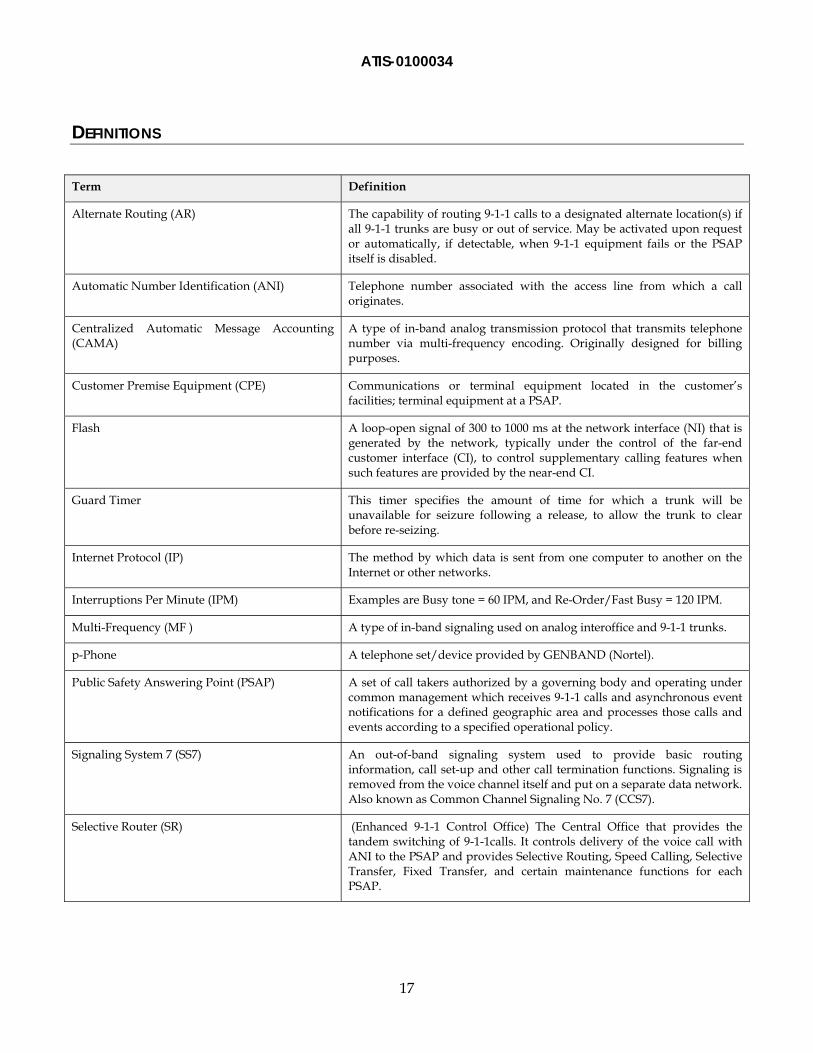
DEFINITIONS
Term Definition
Alternate Routing (AR) The capability of routing 9-1-1 calls to a designated alternate location(s) if all 9-1-1 trunks are busy or out of service. May be activated upon request or automatically, if detectable, when 9-1-1 equipment fails or the PSAP itself is disabled.
Automatic Number Identification (ANI) Telephone number associated with the access line from which a call originates.
Centralized Automatic Message Accounting (CAMA)
A type of in-band analog transmission protocol that transmits telephone number via multi-frequency encoding. Originally designed for billing purposes.
Customer Premise Equipment (CPE) Communications or terminal equipment located in the customer’s facilities; terminal equipment at a PSAP.
Flash A loop-open signal of 300 to 1000 ms at the network interface (NI) that is generated by the network, typically under the control of the far-end customer interface (CI), to control supplementary calling features when such features are provided by the near-end CI.
Guard Timer This timer specifies the amount of time for which a trunk will be unavailable for seizure following a release, to allow the trunk to clear before re-seizing.
Internet Protocol (IP) The method by which data is sent from one computer to another on the Internet or other networks.
Interruptions Per Minute (IPM) Examples are Busy tone = 60 IPM, and Re-Order/Fast Busy = 120 IPM.
Multi-Frequency (MF ) A type of in-band signaling used on analog interoffice and 9-1-1 trunks.
p-Phone A telephone set/device provided by GENBAND (Nortel).
Public Safety Answering Point (PSAP) A set of call takers authorized by a governing body and operating under common management which receives 9-1-1 calls and asynchronous event notifications for a defined geographic area and processes those calls and events according to a specified operational policy.
Signaling System 7 (SS7) An out-of-band signaling system used to provide basic routing information, call set-up and other call termination functions. Signaling is removed from the voice channel itself and put on a separate data network. Also known as Common Channel Signaling No. 7 (CCS7).
Selective Router (SR) (Enhanced 9-1-1 Control Office) The Central Office that provides the tandem switching of 9-1-1calls. It controls delivery of the voice call with ANI to the PSAP and provides Selective Routing, Speed Calling, Selective Transfer, Fixed Transfer, and certain maintenance functions for each PSAP.
ATIS-0100034
18
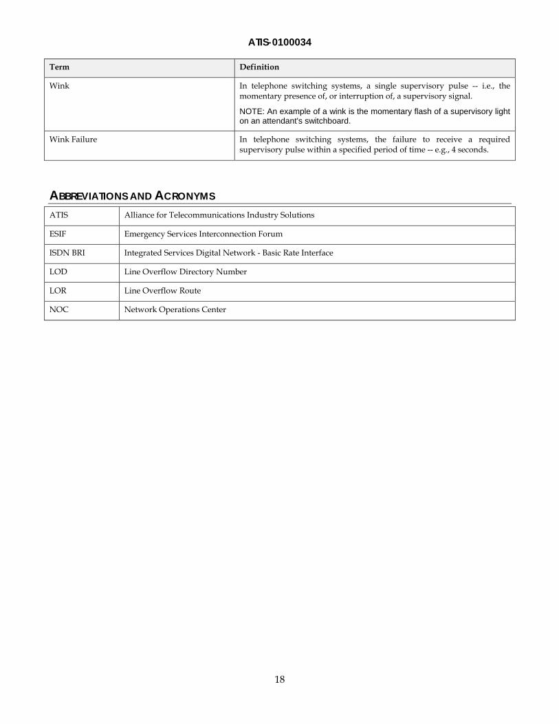
Term Definition
Wink In telephone switching systems, a single supervisory pulse -- i.e., the momentary presence of, or interruption of, a supervisory signal.
NOTE: An example of a wink is the momentary flash of a supervisory light on an attendant's switchboard.
Wink Failure In telephone switching systems, the failure to receive a required supervisory pulse within a specified period of time -- e.g., 4 seconds.
ABBREVIATIONS AND ACRONYMS ATIS Alliance for Telecommunications Industry Solutions
ESIF Emergency Services Interconnection Forum
ISDN BRI Integrated Services Digital Network - Basic Rate Interface
LOD Line Overflow Directory Number
LOR Line Overflow Route
NOC Network Operations Center

ATIS-0100034
19
APPENDIX A – THE SIGNAL STATE DIAGRAM OF PSAP TRUNK This signaling state diagram of a PSAP trunk will help in providing an understanding of the situation and what leads to it (i.e., how is it caused).
The idle condition where a Selective Router seizes the PSAP trunk is state A. This is the start of a 9-1-1 call being offered to a PSAP.
There are three conditions or methods for a call termination: 1) Caller hangs up or disconnects during the call setup process (path N-O-A); 2) Caller hangs up or disconnects prior to the PSAP disconnecting (path G-P-A); or 3) PSAP hangs up before the caller disconnects (path L-M-A).
When the PSAP disconnects first (Path L-M-A), the Selective Router generally waits a minimum of 1.2 seconds before a new call is offered on the circuit to the PSAP because it must determine that the PSAP has hung up, instead of it requesting a conference through an ON-HOOK flash (See path F-H-I-J-K-F).
In the other two paths (N-O-A, or G-P-A), the Selective Router may receive another call, and offer that call to the PSAP sooner than the 1.2 second disconnect period.
Figure 2: SR Signaling States
ATIS-0100034
20
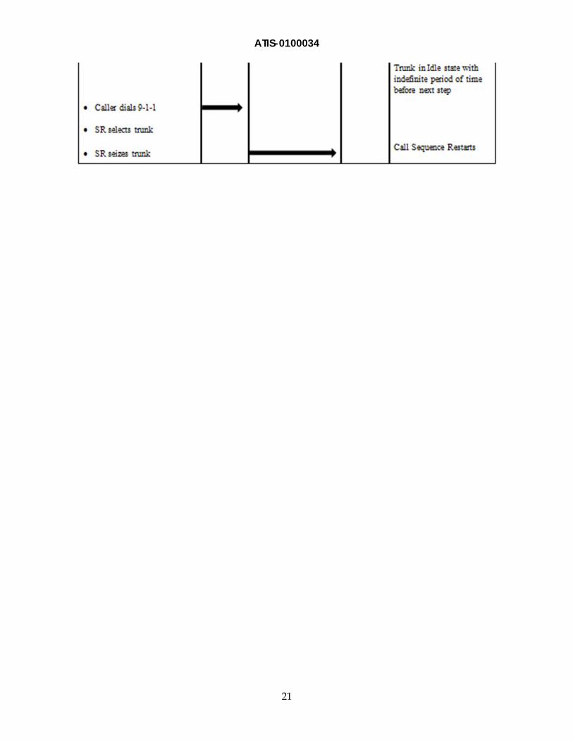
APPENDIX B – THE LADDER DIAGRAM OF A STANDARD CALL TO ACTIVE STATE
ATIS-0100034
21
ATIS-0100034
22
APPENDIX C – THE DISCONNECT OF A CALL, AND THE NO-WINK CONDITION
ATIS-0100034
23
ATIS-0100034
24
APPENDIX D – THE DISCONNECT OF A CALL BEFORE ANSWER (ABANDONED CALL, AND THE NO-WINK CONDITION)
ATIS-0100034
25
ATIS-0100034
26
APPENDIX E – GENBAND DMS-100 E911 LOG MESSAGES E911222 log message: These display the wink failures output by the DMS-100 SR. Wink failures
occur periodically and are not always indicative of a greater trouble. There are two notable exceptions. The first is if the same trunk member fails on two consecutive attempts, this will busy out that trunk, lowering the overall call handling capacity of the PSAP. The second is if there are multiple wink failures over a number (or all) of the members of a PSAP group. This is indicative of a focused overload, mass call, or high call volume event. It is recommended that these logs (delivered via thresholds) be presented as a critical alarm to the network operation center to increase awareness.
E911227 log message: These were traditionally a status log from the switch when a member of a PSAP trunk group is out of service. This log will be output every three minutes from the point where a trunk goes out of service until the last one restores. It is recommended that these logs be presented as a critical alarm to the network operation center to increase awareness.
E911228 log message: This is the message output by the switch when a 911 trunk group member is removed from service. It is recommended that upon a lesser number than the total available trunk members go out of service, this be presented as a critical alarm to the network operation center. This alarm presents the specific trunk member(s) which have been taken out of service.
E911232 log message: These output messages are presented when a call is unable to be delivered to a PSAP call taker and sent to treatment. (Treatment varies by PSAP and can be a busy signal, reorder, or a no circuit available recording.) These logs may not be presented to the network operation center as an alarm, but when combined with the data from the E911242 logs gives a better picture of the volume going to the PSAP. Additionally, we get an idea of the percentage of calls being answered to the percentage of calls being sent to treatment for the impacted PSAP.
E911242 log message: These output messages are generated when the switch sees a call as successfully being delivered to the PSAP. These also may not be presented to the network operation center as an alarm; however, when combined with E911232, it gives us an idea of overall volume and calls completed.

ATIS-0100034
27
APPENDIX F - LAB TEST SUMMARY Service Providers have observed a 9-1-1 service affecting issue that may occur during a sustained heavy call volume event to 9-1-1 causing high call volume overload of the 9-1-1 system.
As explained above, during heavy call volume events to 9-1-1 Public-Service agencies, a 9-1-1 SR may remove PSAP trunks from service -- designated B1 or B2 Connections by NENA in its NENA Standards for E9-1-1 Call Congestion Management (NENA 03-006, Original Issue, March 6, 2003) -- due to Wink Failures on PSAPs serving MF CAMA trunks during call setup. With the removal of each trunk, there is a reduction of call handling capacity of the specific group of trunks serving the PSAP.
During some high call volume events to 9-1-1, Service Providers have observed significant numbers of PSAP serving trunks being removed from service by SRs when the PSAP CPE failed to provide the OFF-HOOK Wink signal during call setup, within the required time frame. ATIS NRSC’s investigation indicates that when the time needed for the 9-1-1 PSAP CPE to be ready for the next 9-1-1 call exceeds the maximum call setup time, the 9-1-1 PSAP CPE does not provide a wink and the 9-1-1 SR counts one No-Wink condition for a trunk. During normal operation at the PSAP’s average busy hour, if the 9-1-1 SR detected a No-Wink condition on a trunk, the call would normally be offered to the next available trunk in a round-robin fashion that would avoid two consecutive call setup failures due to No-Wink on the same trunk. However, if all the other trunks remain busy during a heavy call volume event, the same call will again be offered to the same trunk. If this second offering results in a No-Wink condition, the 9-1-1 SR will busy out that trunk. If the heavy call event persists, potentially all trunks within the affected trunk group will be taken out of service.
A laboratory testing team developed and executed a comprehensive test plan and documented results to demonstrate mass calling conditions. Testing by Service Providers with the test results independently confirmed by GENBAND validated the operational problem of a No-Wink condition and where trunks are being taken out of service as observed in the live environment. Service providers are now able to implement strategies recommended by the SR equipment vendor as well as modified operations procedures to remediate 9-1-1 service impact during 9-1-1 high call volume events. The industry recommended remediation strategies are as follows:
1) Set busy treatment setting to XX percent (SR Service Provider dependent).
2) Apply critical alarm settings for all Wink Failures.
3) Change LOD in applicable DMS Tandems to LOR, on a case by case basis per PSAP.
4) Install a separate group of 9-1-1 PSAP trunks dedicated to answering wireless calls.
5) Implement new testing and NOC notification procedures.