Embed Size (px)
Citation preview
rev. 1/16/2017 CBS, MANUAL.doc
Copyright 2017 Vestil Manufacturing Corp. Page 1 of 20
CBS-Series Counterbalanced Stackers Instruction Manual
Receiving Instructions: After delivery, remove the packaging from the product. Inspect the product closely to determine whether it
sustained damage during transport. If damage is discovered, record a complete description of it on the bill of lading. If the product is undamaged, discard the packaging.
NOTE: Compliance with laws, regulations, codes, and non-voluntary standards enforced in the location where the product
is used is exclusively the responsibility of the end-user.
VESTIL MANUFACTURING CORP. 2999 North Wayne Street, P.O. Box 507, Angola, IN 46703 Telephone: (260) 665-7586 -or- Toll Free (800) 348-0868
Fax: (260) 665-1339 www.vestilmfg.com e-mail: [email protected]
Table of Contents Signal words………………...…………………………………………………………………………................................................... 2 Improper use might cause personal injuries…………………………..………………………………………………………………… 2 Specifications…………………...……………………..……………………………………………………………………………………. 3 Diagram of Hydraulic System……………………………………………………………………………………………………………… 3 FIG. 1: CBS-64-1 (AC & DC) exploded parts diagram & parts list………..…………………………………………......................... 4 FIG. 2: CBS-76-1 (AC & DC) exploded parts diagram & parts list……..………………………………………………………………5 FIG. 3: 115VAC modular power unit electrical circuit diagram……..………………………...……………………………………….. 6 FIG. 4: 12VDC modular power unit electrical circuit diagram……………………..…………………………………………………... 6 FIG. 5: 3-phase AC modular power unit diagram……………………………………………………………………………………….. 7 FIG. 6: Single phase 208 / 230 VAC modular power unit diagram…………………….………………………………………........... 7 FIGS. 7A & 7B: 12VDC modular power unit layout (parts 1 & 2)………………………..……………………..……………………... 8 - 9 FIG. 8: AC modular power unit layout……………………………………………………………..……………………………………... 10 FIG. 9: DC modular power unit exploded parts diagram……………………………………………………………………………….. 11 FIGS. 10A & 10B: AC modular power unit exploded parts diagram…………………………………………………………………... 12-13 Loading Instructions………………………………………………………………………………………………………………………… 14 Hydraulic system……………………………………………………………………………………………………………………………. 14 DC-Powered hydraulic system troubleshooting guide………………………………………………………………………………….. 15-16 Battery charger operation………………………………………………………………………………………………………………….. 17 Inspections & Maintenance……………………………………………………………....................................................................... 18 Labeling diagram…………..……………………………………………………………………………………………………………….. 19 Limited warranty…………………………………………………………………………………………………………………………….. 20
rev. 1/16/2017 CBS, MANUAL.doc
Copyright 2017 Vestil Manufacturing Corp. Page 2 of 20
SIGNAL WORDS:
This manual uses SIGNAL WORDS to identify dangers that might arise during use the probable seriousness of those injuries, if the product is misused in the ways described. Other signal words call attention to uses of the product likely cause property damage. Signal words used in this manual appear below along with their definitions.
Identifies a hazardous situation which, if not avoided, COULD result in DEATH or SERIOUS INJURY.
Identifies practices likely to result in product/property damage, such as operation that might damage the product.
Improper Use Might Cause Personal Injuries: Vestil diligently strives to identify foreseeable hazards associated with the use of its products. However, material
handling is inherently dangerous and no manual can address every conceivable risk. The end-user ultimately is responsible for exercising sound judgment at all times.
Improper or careless use of this product might result in serious personal injuries or even death. Read and understand the entire manual before assembling, using or servicing the product. Read the manual to refresh your understanding of proper use and maintenance procedures. DO NOT modify the product in any way UNLESS you first obtain written approval from Vestil. Unauthorized modifications might make the lift unsafe to use and automatically void the Limited Warranty (see p. 20). DO NOT exceed the maximum rated load (see “Specifications” table on p. 3; Label 287 on product). Inspect the product before each use according to the instructions on p. 18. A. DO NOT use this product if the inspection reveals structural damage. Examples of structural damage include,
but are not limited to, the following: 1) Cracked, broken or deformed load-bearing members (forks, fork carriage, mast, wheels, and frame); 2) cracked welds; 3) corrosion or severe wear; 4) damaged, e.g. leaking, hydraulic system (cylinder, hoses, reservoir, etc.). Remove the product from service if it fails any part of the inspection. DO NOT use the product until it is fully restored to normal condition. In the event that part of the hydraulic system is damaged, AVOID contact with pressurized hydraulic oil (leaking from a ruptured hose, for instance). High pressure oil easily punctures skin which can cause injury such as gangrene.
B. DO NOT use the product if any unusual noise or movement is observed. If a malfunction occurs, remove the unit from service and notify your supervisor & maintenance personnel about the issue.
C. ONLY use manufacturer-approved replacement parts. DO NOT change the setting of the pressure relief valve. Whenever using this product, carefully watch the forks and the load. DO NOT use this device UNLESS all product labels (see “Labeling Diagram” on p. 19) are readable and undamaged AND all machine guards (i.e. the expanded metal mast guard and formed wheel guards) are in place. This product is NOT a personnel lift. DO NOT use this device to lift people. DO NOT walk or stand beneath the forks at any time. DO NOT leave the stacker unattended while it is loaded. ALWAYS fully lower the forks and engage the caster brakes before leaving the unit unattended. ONLY transport loads with the forks no higher than is necessary to fully support the load and avoid obstacles. To lift a pallet with this stacker, drive the unit as far forward as possible until the pallet firmly contacts the upright portions of both forks (i.e. the “heels”). DO NOT continue to push the “UP” button on the controller if the forks do not rise. Remove the unit from service and report the problem to maintenance personnel.
rev. 1/16/2017 CBS, MANUAL.doc
Copyright 2017 Vestil Manufacturing Corp. Page 3 of 20
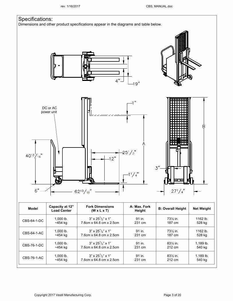
Specifications: Dimensions and other product specifications appear in the diagrams and table below.
Model Capacity at 12”
Load Center Fork Dimensions
(W x L x T) A: Max. Fork
Height B: Overall Height Net Weight
CBS-64-1-DC 1,000 lb. ~454 kg
3” x 251/2” x 1” 7.6cm x 64.8 cm x 2.5cm
91 in. 231 cm
73½ in. 187 cm
1162 lb. 528 kg
CBS-64-1-AC 1,000 lb. ~454 kg
3” x 251/2” x 1” 7.6cm x 64.8 cm x 2.5cm
91 in. 231 cm
73½ in. 187 cm
1162 lb. 528 kg
CBS-76-1-DC 1,000 lb. ~454 kg
3” x 251/2” x 1” 7.6cm x 64.8 cm x 2.5cm
91 in. 231 cm
83½ in. 212 cm
1,189 lb. 540 kg
CBS-76-1-AC 1,000 lb. ~454 kg
3” x 251/2” x 1” 7.6cm x 64.8 cm x 2.5cm
91 in. 231 cm
83½ in. 212 cm
1,189 lb. 540 kg
DC or AC power unit
rev. 1/16/2017 CBS, MANUAL.doc
Copyright 2017 Vestil Manufacturing Corp. Page 4 of 20
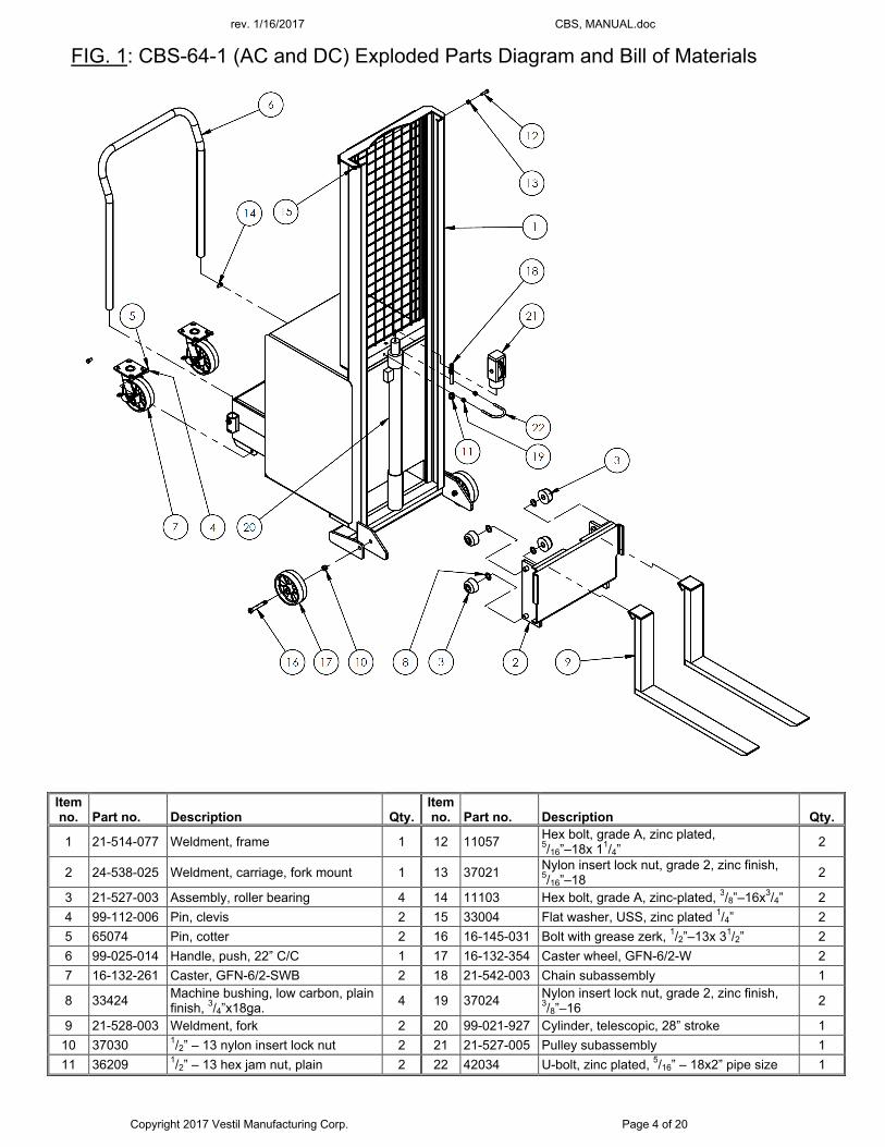
FIG. 1: CBS-64-1 (AC and DC) Exploded Parts Diagram and Bill of Materials
Item no. Part no. Description Qty.
Item no. Part no. Description Qty.
1 21-514-077 Weldment, frame 1 12 11057 Hex bolt, grade A, zinc plated, 5/16”–18x 11/4”
2
2 24-538-025 Weldment, carriage, fork mount 1 13 37021 Nylon insert lock nut, grade 2, zinc finish, 5/16”–18
2
3 21-527-003 Assembly, roller bearing 4 14 11103 Hex bolt, grade A, zinc-plated, 3/8”–16x3/4” 2
4 99-112-006 Pin, clevis 2 15 33004 Flat washer, USS, zinc plated 1/4” 2
5 65074 Pin, cotter 2 16 16-145-031 Bolt with grease zerk, 1/2”–13x 31/2” 2
6 99-025-014 Handle, push, 22” C/C 1 17 16-132-354 Caster wheel, GFN-6/2-W 2
7 16-132-261 Caster, GFN-6/2-SWB 2 18 21-542-003 Chain subassembly 1
8 33424 Machine bushing, low carbon, plain finish, 3/4”x18ga.
4 19 37024 Nylon insert lock nut, grade 2, zinc finish, 3/8”–16
2
9 21-528-003 Weldment, fork 2 20 99-021-927 Cylinder, telescopic, 28” stroke 1
10 37030 1/2” – 13 nylon insert lock nut 2 21 21-527-005 Pulley subassembly 1
11 36209 1/2” – 13 hex jam nut, plain 2 22 42034 U-bolt, zinc plated, 5/16” – 18x2” pipe size 1
Guard not shown for clarity
rev. 1/16/2017 CBS, MANUAL.doc
Copyright 2017 Vestil Manufacturing Corp. Page 5 of 20
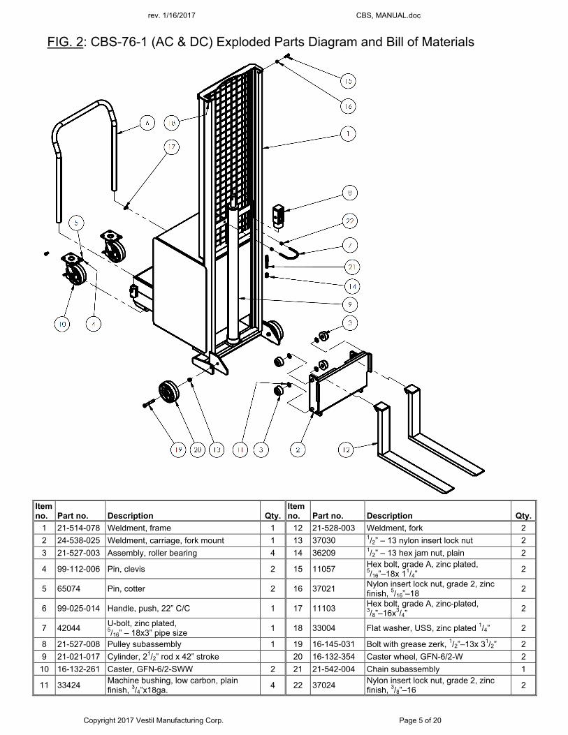
FIG. 2: CBS-76-1 (AC & DC) Exploded Parts Diagram and Bill of Materials
Item no. Part no. Description Qty.
Item no. Part no. Description Qty.
1 21-514-078 Weldment, frame 1 12 21-528-003 Weldment, fork 2
2 24-538-025 Weldment, carriage, fork mount 1 13 37030 1/2” – 13 nylon insert lock nut 2
3 21-527-003 Assembly, roller bearing 4 14 36209 1/2” – 13 hex jam nut, plain 2
4 99-112-006 Pin, clevis 2 15 11057 Hex bolt, grade A, zinc plated, 5/16”–18x 11/4”
2
5 65074 Pin, cotter 2 16 37021 Nylon insert lock nut, grade 2, zinc finish, 5/16”–18
2
6 99-025-014 Handle, push, 22” C/C 1 17 11103 Hex bolt, grade A, zinc-plated, 3/8”–16x3/4”
2
7 42044 U-bolt, zinc plated, 5/16” – 18x3” pipe size
1 18 33004 Flat washer, USS, zinc plated 1/4” 2
8 21-527-008 Pulley subassembly 1 19 16-145-031 Bolt with grease zerk, 1/2”–13x 31/2” 2
9 21-021-017 Cylinder, 21/2” rod x 42” stroke 20 16-132-354 Caster wheel, GFN-6/2-W 2
10 16-132-261 Caster, GFN-6/2-SWW 2 21 21-542-004 Chain subassembly 1
11 33424 Machine bushing, low carbon, plain finish, 3/4”x18ga.
4 22 37024 Nylon insert lock nut, grade 2, zinc finish, 3/8”–16
2
rev. 1/16/2017 CBS, MANUAL.doc
Copyright 2017 Vestil Manufacturing Corp. Page 6 of 20
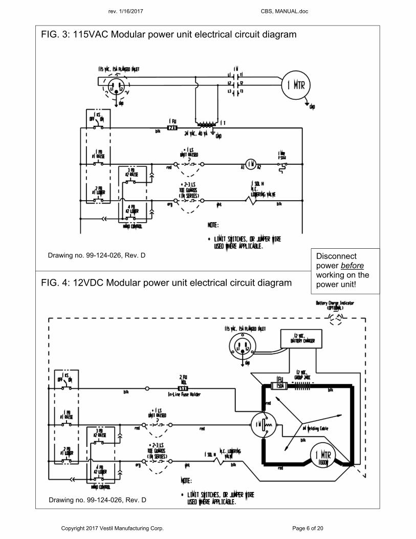
FIG. 3: 115VAC Modular power unit electrical circuit diagram
FIG. 4: 12VDC Modular power unit electrical circuit diagram
Disconnect power before working on the power unit!
Drawing no. 99-124-026, Rev. D
Drawing no. 99-124-026, Rev. D
rev. 1/16/2017 CBS, MANUAL.doc
Copyright 2017 Vestil Manufacturing Corp. Page 7 of 20
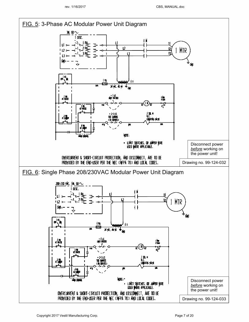
FIG. 5: 3-Phase AC Modular Power Unit Diagram
Disconnect power before working on the power unit!
Drawing no. 99-124-032
FIG. 6: Single Phase 208/230VAC Modular Power Unit Diagram
Drawing no. 99-124-033
Disconnect power before working on the power unit!
rev. 1/16/2017 CBS, MANUAL.doc
Copyright 2017 Vestil Manufacturing Corp. Page 8 of 20
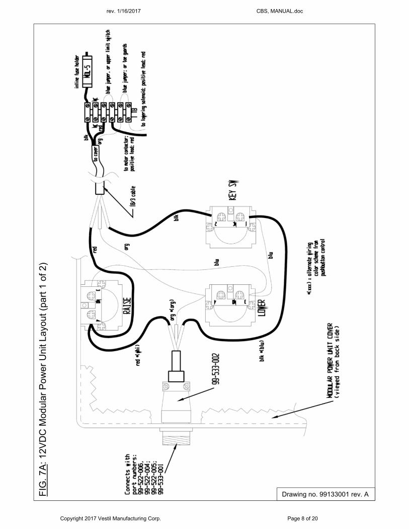
FIG
. 7A
: 12V
DC
Mod
ular
Pow
er U
nit L
ayou
t (pa
rt 1
of 2
)
Drawing no. 99133001 rev. A
rev. 1/16/2017 CBS, MANUAL.doc
Copyright 2017 Vestil Manufacturing Corp. Page 9 of 20
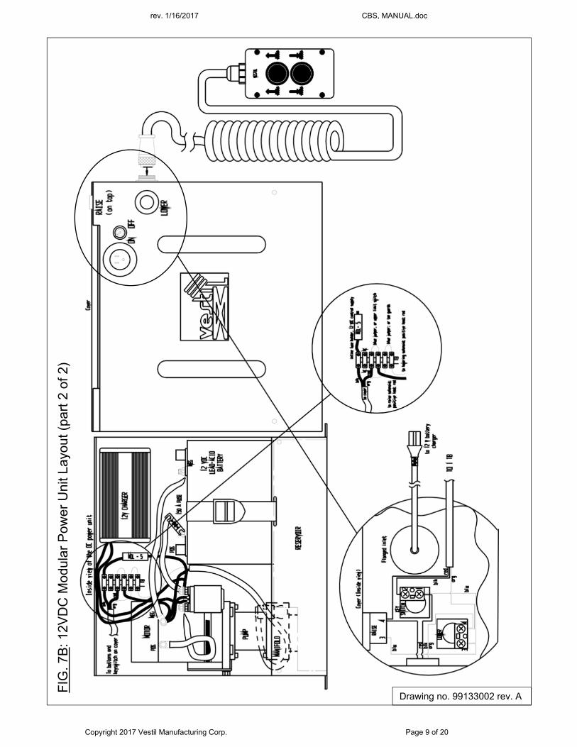
FIG
. 7B
: 12V
DC
Mod
ular
Pow
er U
nit L
ayou
t (pa
rt 2
of 2
)
Drawing no. 99133002 rev. A
rev. 1/16/2017 CBS, MANUAL.doc
Copyright 2017 Vestil Manufacturing Corp. Page 10 of 20
F
IG. 8
: AC
Mod
ular
Pow
er U
nit L
ayou
t
Drawing no. 99133003 rev. A
rev. 1/16/2017 CBS, MANUAL.doc
Copyright 2017 Vestil Manufacturing Corp. Page 11 of 20
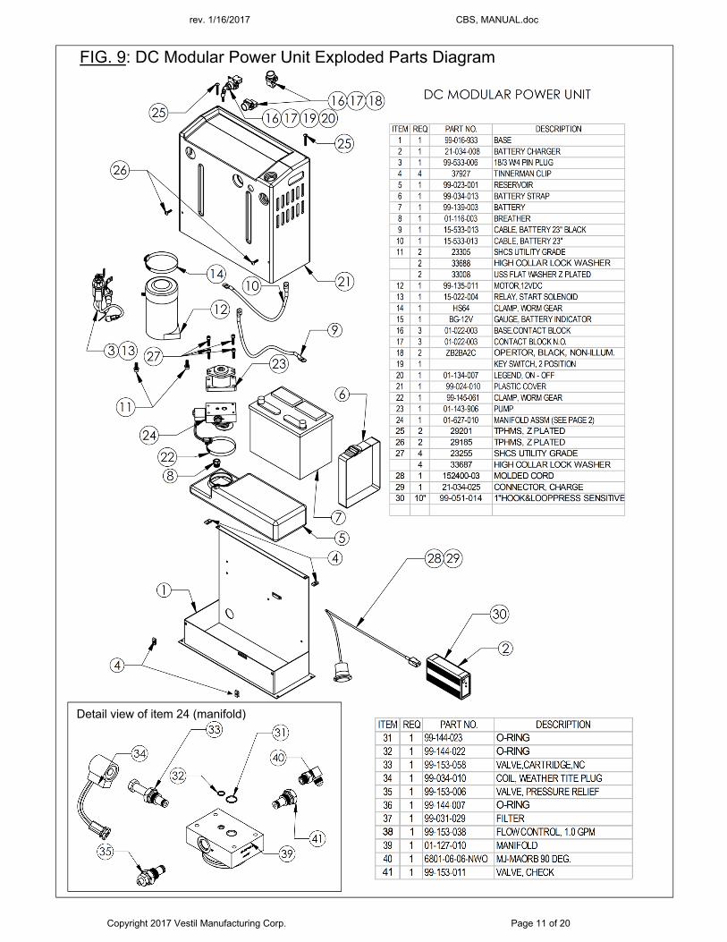
FIG. 9: DC Modular Power Unit Exploded Parts Diagram
Detail view of item 24 (manifold)
rev. 1/16/2017 CBS, MANUAL.doc
Copyright 2017 Vestil Manufacturing Corp. Page 12 of 20
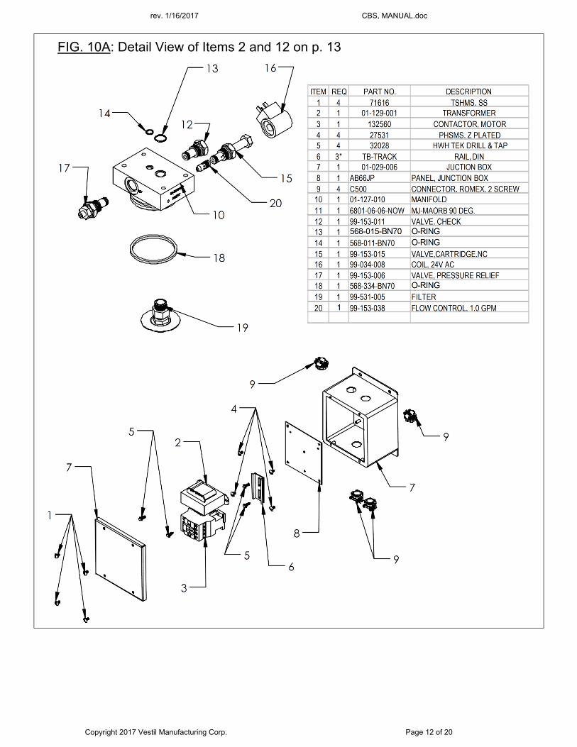
FIG. 10A: Detail View of Items 2 and 12 on p. 13
rev. 1/16/2017 CBS, MANUAL.doc
Copyright 2017 Vestil Manufacturing Corp. Page 13 of 20
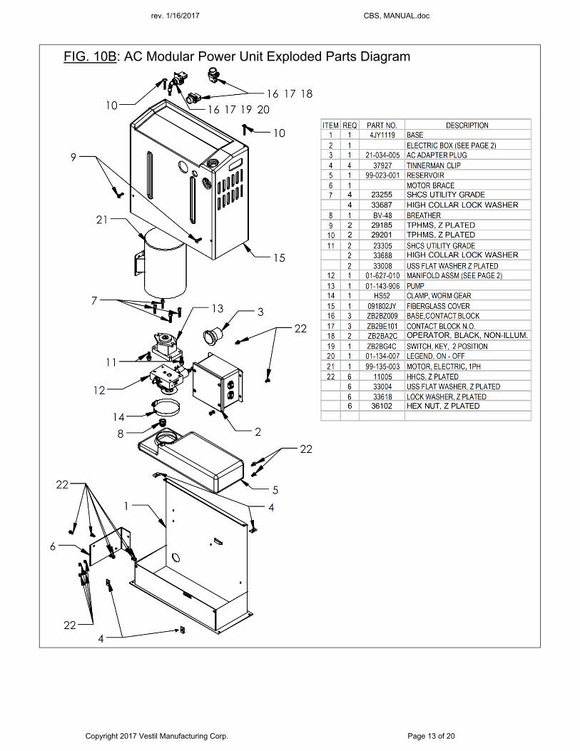
FIG. 10B: AC Modular Power Unit Exploded Parts Diagram
rev. 1/16/2017 CBS, MANUAL.doc
Copyright 2017 Vestil Manufacturing Corp. Page 14 of 20
LOADING INSTRUCTIONS The capacity of the unit appears on label 287 (see p. 19). DO NOT apply a load to the forks that exceeds the capacity.
When loading the stacker, always follow these guidelines: 1. The load should firmly contact the upright portions of the forks; 2. DO NOT apply a load to the tips of the forks; 3. Center the load on the forks; 4. Only transport loads in the lowered position.
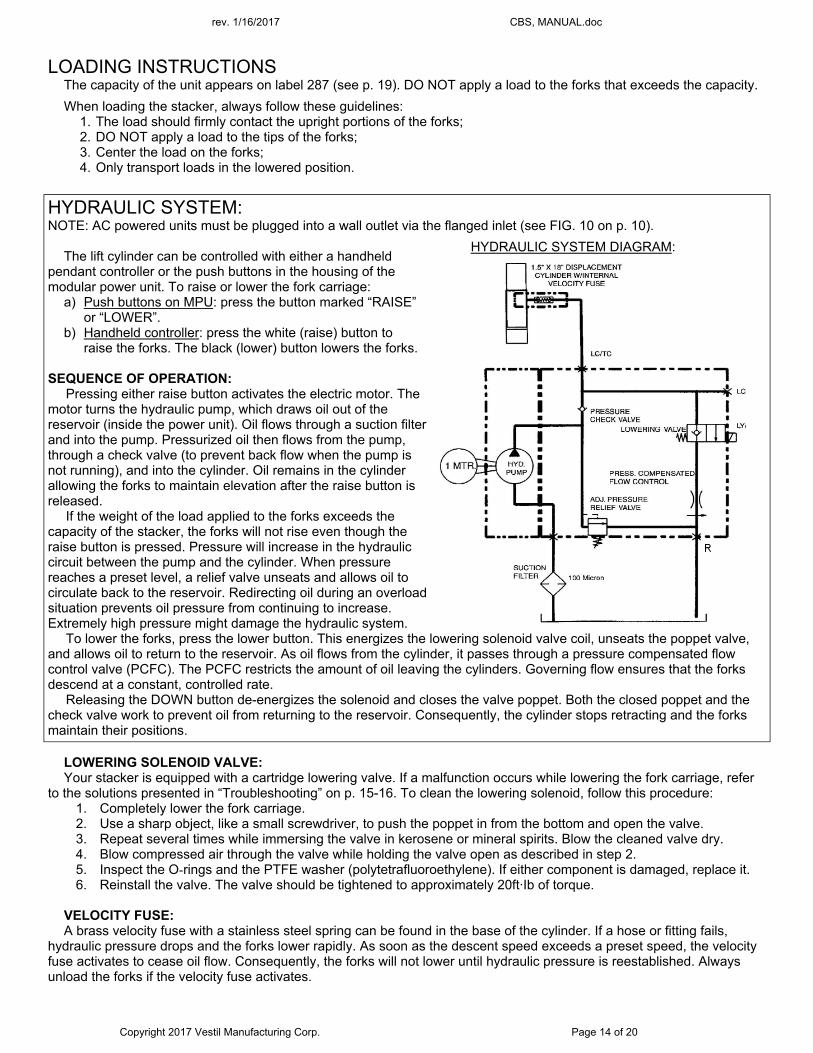
HYDRAULIC SYSTEM: NOTE: AC powered units must be plugged into a wall outlet via the flanged inlet (see FIG. 10 on p. 10).
The lift cylinder can be controlled with either a handheld
pendant controller or the push buttons in the housing of the modular power unit. To raise or lower the fork carriage:
a) Push buttons on MPU: press the button marked “RAISE” or “LOWER”.
b) Handheld controller: press the white (raise) button to raise the forks. The black (lower) button lowers the forks.
SEQUENCE OF OPERATION:
Pressing either raise button activates the electric motor. The motor turns the hydraulic pump, which draws oil out of the reservoir (inside the power unit). Oil flows through a suction filter and into the pump. Pressurized oil then flows from the pump, through a check valve (to prevent back flow when the pump is not running), and into the cylinder. Oil remains in the cylinder allowing the forks to maintain elevation after the raise button is released.
If the weight of the load applied to the forks exceeds the capacity of the stacker, the forks will not rise even though the raise button is pressed. Pressure will increase in the hydraulic circuit between the pump and the cylinder. When pressure reaches a preset level, a relief valve unseats and allows oil to circulate back to the reservoir. Redirecting oil during an overload situation prevents oil pressure from continuing to increase. Extremely high pressure might damage the hydraulic system.
To lower the forks, press the lower button. This energizes the lowering solenoid valve coil, unseats the poppet valve, and allows oil to return to the reservoir. As oil flows from the cylinder, it passes through a pressure compensated flow control valve (PCFC). The PCFC restricts the amount of oil leaving the cylinders. Governing flow ensures that the forks descend at a constant, controlled rate.
Releasing the DOWN button de-energizes the solenoid and closes the valve poppet. Both the closed poppet and the check valve work to prevent oil from returning to the reservoir. Consequently, the cylinder stops retracting and the forks maintain their positions.
LOWERING SOLENOID VALVE: Your stacker is equipped with a cartridge lowering valve. If a malfunction occurs while lowering the fork carriage, refer
to the solutions presented in “Troubleshooting” on p. 15-16. To clean the lowering solenoid, follow this procedure: 1. Completely lower the fork carriage. 2. Use a sharp object, like a small screwdriver, to push the poppet in from the bottom and open the valve. 3. Repeat several times while immersing the valve in kerosene or mineral spirits. Blow the cleaned valve dry. 4. Blow compressed air through the valve while holding the valve open as described in step 2. 5. Inspect the O-rings and the PTFE washer (polytetrafluoroethylene). If either component is damaged, replace it. 6. Reinstall the valve. The valve should be tightened to approximately 20ft·Ib of torque.
VELOCITY FUSE: A brass velocity fuse with a stainless steel spring can be found in the base of the cylinder. If a hose or fitting fails,
hydraulic pressure drops and the forks lower rapidly. As soon as the descent speed exceeds a preset speed, the velocity fuse activates to cease oil flow. Consequently, the forks will not lower until hydraulic pressure is reestablished. Always unload the forks if the velocity fuse activates.
HYDRAULIC SYSTEM DIAGRAM:
rev. 1/16/2017 CBS, MANUAL.doc
Copyright 2017 Vestil Manufacturing Corp. Page 15 of 20
Air in the hydraulic circuit can also cause the velocity fuse to activate although no failure has occurred. To reset the velocity fuse, activate the pump by jogging the raise button. Immediately after resetting the velocity fuse, fully lower the forks. Cycle the forks all the way to the top of the mast and back down several times to purge air from the system.
AIR BLEED PROCEDURE: If the forks descend very slowly or do not lower, air probably is trapped in the hydraulic circuit and must be bled from
the system. To bleed air from the circuit: 1.) Completely unload and lower the forks. 2.) Loosen the bleeder screw at the top of the cylinder approximately 1/4 to 1/2 turn to allow trapped air to escape. Jog the motor to push air out of the system. 3.) When air is no longer present in the cylinder, only clear hydraulic fluid will flow from the bleeder screw opening. 4.) Retighten the bleeder screw.
DC-POWERED HYDRAULIC SYSTEM TROUBLESHOOTING GUIDE Before performing maintenance on this product, unload the forks and completely lower the carriage.
Observation Possible Cause Remedy 1. Unit does not raise, motor does not run a. Low battery voltage. (Check light)
b. All chassis connections to negative post of battery not made well.
a. Recharge battery b. Check and tighten or clean connections if necessary.
2. Unit does not raise but motor is running or humming.
c. Voltage at motor terminals might be too low to run pump at existing load. d. Fluid level in reservoir is low. e. Load exceeds capacity requirements. Relief valve is allowing hydraulic fluid to flow back into the reservoir. f. Suction filter is clogged, starving pump. g. Suction line may be leaking air, due to loose fittings. h. Filter/Breather cap on tank might be clogged. i. Lowering solenoid valve might be energized by faulty wiring or might be stuck open. j. Hydraulic pump might be inoperative.
c. Measure voltage at motor terminals or as near as possible, while pump is running under load. Check for loose connections. d. Add fluid. Refer to Owner's Manual for proper fluid levels. e. DO NOT CHANGE RELIEF VALVE SETTING. Instead, reduce the load to rated capacity. f. Remove and clean. g. Inspect all fittings for proper tightness. h. Remove and clean. i. Remove lowering solenoid valve. Check and clean. (Refer to “Lowering Solenoid Valves”.) j. Disconnect hydraulic line at power unit. Put pressure line in a large container and operate the pump. If no output, check the pump motor coupling which may be defective, and correct as necessary. If pump is worn, consult factory for replacement parts.
3. Unit rises too slowly. k. Foreign material stuck in down solenoid valve, causing some fluid to flow back into the reservoir. l. Foreign material clogging suction filter, or breather cap, or a hose is pinched. m. Low motor voltage. n. Unit overloaded. o. Inoperative pump.
k. Lower the deck. Remove the down solenoid valve and clean. (Refer to Hydraulic Section of Owners Manual). l. Correct as necessary. (See also, 2(f), (h)). m. See 2 (b) n. See 2 (e) o. See 2 (j)
4. Motor labors or is excessively hot. p. Voltage may be low. q. Oil starvation causing pump to bind & high internal heat develops. If this occurs, pump can be permanently damaged. r. Binding cylinders.
p. See 2 (b) q. See 2 (d), (f), (g), (h), (j) r. Align cylinders correctly.
5. "Spongy· or "Jerky· unit operation. s. Fluid starvation. t. Air in system.
s. See 2 (d), (f), (g), (j) t. See air bleed procedure (p. 15).
6. Unit lowers too slowly when loaded. u. Lowering solenoid valve filter screen clogged. v. Pinched tube or hose. w. Foreign material in flow control valve. x. Binding cylinders.
u. Remove lowering solenoid valve and clean filter screen. v. Correct as necessary. w. Remove and clean flow control valve. Refer to Hydraulic System Diagram on p. 14). x. Align cylinders correctly.
rev. 1/16/2017 CBS, MANUAL.doc
Copyright 2017 Vestil Manufacturing Corp. Page 16 of 20
y. Foreign material in velocity fuse. y. Remove and clean velocity fuse. Refer to Hydraulic System Diagram on p. 3).
7. Unit lowers too quickly. z. Foreign material stuck in flow control valve. (In this case, carriage initially lowers at a normal rate but accelerates as the carriage descends).
z. Remove flow control valve from the valve block and clean. (Refer to Hydraulic System Diagram on p. 3).
8. Unit raises then lowers slowly. aa. Lowering solenoid valve may be incorrectly wired or is stuck open bb. Check valve may be stuck open. cc. Check for leaking hoses, fittings, pipes. dd. Cylinder packings may be worn or damaged.
aa. See 3 (a). bb. Remove and clean check valve; (Refer to Hydraulic Section of Owner's Manual). cc. See 2 (c). dd. Replace packings (contact factory for replacement parts).
9. Carriage elevates, but does not lower. ee. Incorrect lowering solenoid valve wiring. ff. Lowering solenoid valve is stuck. gg. Faulty lowering solenoid coil. hh. Binding cylinders. ii. If the carriage lowers too rapidly, air is present in the hydraulic system causing the velocity fuse to activate and shut off the oil flow from the cylinders. Consequently, the deck will not lower.
ee. Correct per diagram (p. 6-7). ff. Lightly tap down the solenoid coil body to seat it properly. (DO NOT hit coil hard as it will permanently damage the internal system. DO NOT remove the solenoid valve from the block because the carriage will descend dangerously quickly. gg. Remove and replace. DO NOT remove the down solenoid valve fro the block as the unit will come down at a dangerous speed. hh. See 4 (c). ii. To unlock, re-pressurize the hydraulic system.
rev. 1/16/2017 CBS, MANUAL.doc
Copyright 2017 Vestil Manufacturing Corp. Page 17 of 20
BATTERY CHARGER OPERATION Working with or near lead acid batteries is dangerous.
Batteries contain sulfuric acid and produce explosive gases. A battery explosion could result in loss of eyesight or serious burns. DO NOT expose the battery to sparks or flames, i.e. DO NOT SMOKE NEAR THE BATTERY!! ONLY charge batteries in clean, dry, and well ventilated locations. DO NOT lay tools or any metallic item on top of a battery. When working with batteries, remove personal items such as rings, bracelets, necklaces, and watches. A battery can produce enough voltage to weld jewelry to metal. Always have plenty of fresh water and soap nearby in case contact with battery acid occurs. Operating the battery with a low battery voltage can cause premature motor contact failure. The charger is equipped with an external ground wire (small green). During installation the charger must be grounded to the equipment which it is connected to. Be sure this wire is always connected to the chassis, frame, or other metallic surface considered to be ground. Confirm that all battery connections are sound and clean. Replace defective cords and wires immediately. DO NOT use the charger if the flanged inlet is damaged. DO NOT connect the charger to a damaged extension cord.
Every DC powered stacker is equipped with an onboard battery charger having a flanged electrical inlet. The charger is current limited and will not exceed its rated output even if loads are placed on the battery while it is charging. The charger fuse will blow if it is connected in reverse polarity.
To charge the battery: 1.) Plug the charger into an 115V 60 Hz receptacle by connecting the flanged inlet on the charger to an extension cord. Plug the other end of the cord to a wall socket. Use a short, thick extension cord. 2.) When properly connected, the charge LED will indicate the status of charge current flowing to the battery.
If only the red LED is on, the charger is providing full output to the battery. If both the red and green LED's are on, the charger is "topping off" the battery. When only the green LED is on, the unit is providing a "float" (maintenance) charge. DO NOT leave the charger on for long periods after the battery is fully charged.
3.) Unplug the charger before using the stacker.
TROUBLESHOOTING If the charger does not work: 1) Make sure all battery connections are electrically and mechanically sound. 2) Confirm that the AC source (e.g. wall socket) for power. 3) Check the fuse. Replace only with a fuse having the same rating as originally supplied. 4) Determine battery condition. It may take some time before current begins to flow through a highly sulfated battery.
rev. 1/16/2017 CBS, MANUAL.doc
Copyright 2017 Vestil Manufacturing Corp. Page 18 of 20
INSPECTIONS & MAINTENANCE:
Proper use, maintenance, and storage are essential for this product to function properly. o Always use this product in accordance with the instructions in this manual and consistent with any training relevant to machines, devices, etc. used in conjunction with this product. o Relieve hydraulic pressure whenever the unit is not in use by fully lowering the forks. o Keep the product clean & dry. Lubricate moving parts at least once per month. o ONLY use manufacturer-approved replacement parts. Vestil is not responsible for issues or malfunctions that result from the use of unapproved replacement parts. o Do not use brake fluid or jack oils in the hydraulic system. If oil is needed, use an anti-wear hydraulic oil with a viscosity grade of 150 SUS at 100°F, (ISO 32 cSt @ 40°C), or Dexron transmission fluid. o Contact the manufacturer for SDS information.
Inspections: (A) Before Each Use—visually inspect the following:
1. Electrical system: inspect the modular power unit and electrical wiring for damage. 2. Casters: examine each caster and confirm normal operating condition, i.e. rolls smoothly without wobbling, not
cracked, or severely worn, 3. Hydraulic hoses: check for pinches, punctures, and loose connections. 4. Structure: inspect the frame for deformations and cracked welds. 5. Forks, carriage and mast: cycle the forks up and down while listening and watching unusual noise, motion, or
binding. 6. Pushbutton controller: inspect the controller and look for damage that exposes wiring inside the controller
housing.
(B) Monthly Inspections--at least once per month thoroughly inspect the following: 1. Oil level. Oil should be 1" to 11/2" below the top of the tank when the forks are fully lowered. Add oil as necessary.
Look for oil leaking from hoses, the cylinder, or the reservoir. See “Troubleshooting” (p. 15-16). 2. Battery: check the water level in the battery. (DC models only) 3. Clevis pins and pivot points: inspect for excessive wear. 4. Modular power unit, wiring, limit switches, and pushbutton controller: Check for severely worn or damaged
hydraulic hoses, electrical wires, and cords. Repair as necessary. 5. Roller bearings (see p. 4-5): check rollers and retaining hardware for normal condition. 6. Forks, carriage and mast: cycle the forks up and down. Listen and watch for unusual noise, motion (e.g. binding). 7. Labels (see “Labeling diagram”; p. 19): confirm that all labels are in place and in good, readable condition. 8. Surfaces: remove dirt and debris.
(C) Yearly Inspection Hydraulic oil should be changed at least once a year or sooner if the oil darkens or becomes gritty. Flush the reservoir before refilling. Similarly, if the oil appears milky, water is present and the oil should be changed. Maintenance: Implement a regular maintenance program to ensure that the stacker remains in normal condition. ANSI/ITSDF standard B56.10 describes some recommended maintenance procedures which should be followed. A copy of the standard is downloadable for free at http://www.itsdf.org/. The following steps should be applied in conjunction with those recommendations.
Step 1: Tag the unit, “Out of Service.”
Step 2: Perform a monthly inspection. If deformity, corrosion, rusting, or excessive wear of frame members is noticed, DO NOT continue to use the stacker. Contact Vestil for instructions. If the fork carriage does not move smoothly or makes noise as it moves up or down the mast, apply a silicon wax or silicon spray to the inside of the mast frame.
Step 3: Remove any dirt or other matter from the forks and other surfaces.
Step 4: Perform all other necessary adjustments and/or repairs. DO NOT modify the stacker. A modification is a change that alters the machine from normal operating condition, like bending frame members or removing parts.
Step 5: Make a dated record of the repairs, adjustments and/or replacements.
rev. 1/16/2017 CBS, MANUAL.doc
Copyright 2017 Vestil Manufacturing Corp. Page 19 of 20
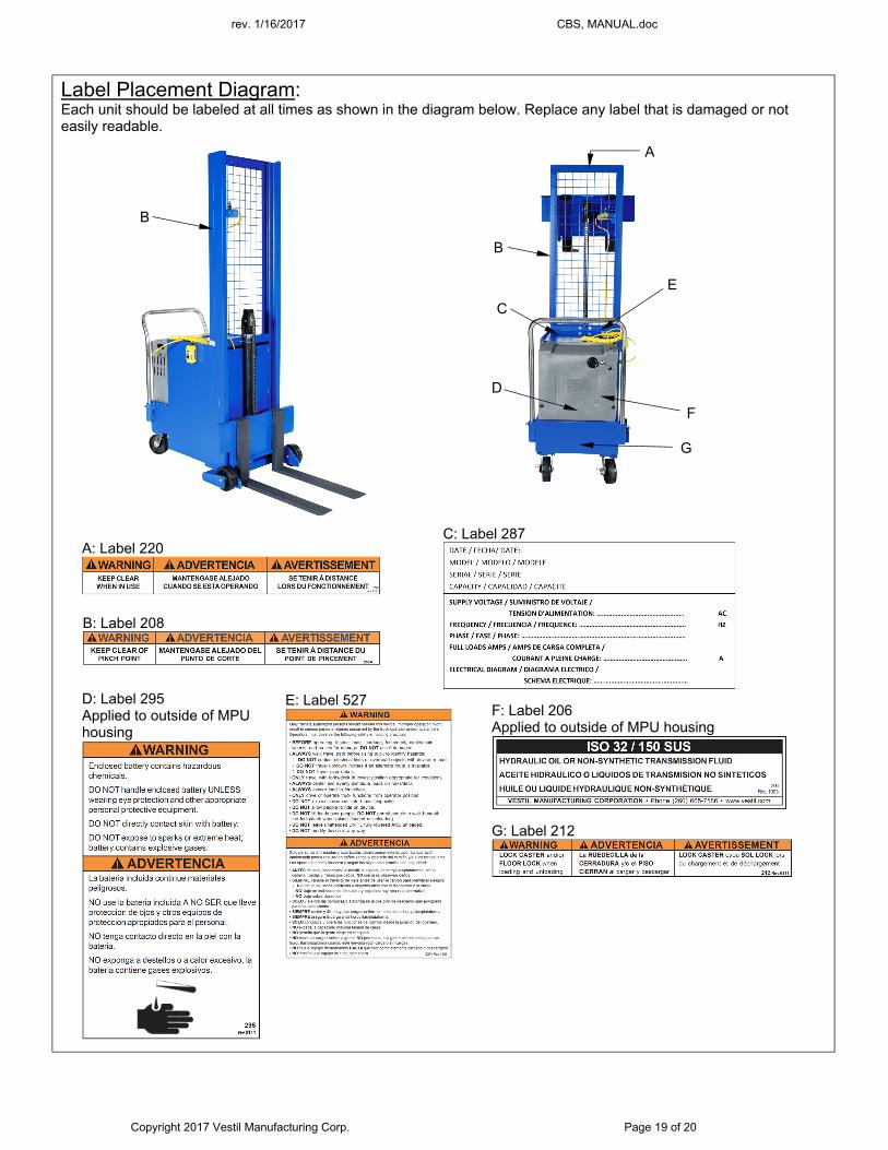
Label Placement Diagram: Each unit should be labeled at all times as shown in the diagram below. Replace any label that is damaged or not easily readable.
A
E
C
G
D
F
B
A: Label 220
B: Label 208
D: Label 295 Applied to outside of MPU housing
F: Label 206 Applied to outside of MPU housing
C: Label 287
G: Label 212
E: Label 527
B
rev. 1/16/2017 CBS, MANUAL.doc
Copyright 2017 Vestil Manufacturing Corp. Page 20 of 20
LIMITED WARRANTY
Vestil Manufacturing Corporation (“Vestil”) warrants this product to be free of defects in material and workmanship during the warranty period. Our warranty obligation is to provide a replacement for a defective original part if the part is covered by the warranty, after we receive a proper request from the warrantee (you) for warranty service.
Who may request service? Only a warrantee may request service. You are a warrantee if you purchased the product from Vestil or from an authorized distributor AND Vestil has been fully paid.
What is an “original part”? An original part is a part used to make the product as shipped to the warrantee.
What is a “proper request”? A request for warranty service is proper if Vestil receives: 1) a photocopy of the Customer Invoice that displays the shipping date; AND 2) a written request for warranty service including your name and phone number. Send requests by any of the following methods:
Mail Fax Email Vestil Manufacturing Corporation (260) 665-1339 [email protected] 2999 North Wayne Street, PO Box 507 Phone Angola, IN 46703 (260) 665-7586
In the written request, list the parts believed to be defective and include the address where replacements should be delivered.
What is covered under the warranty? After Vestil receives your request for warranty service, an authorized representative will contact you to determine whether your claim is covered by the warranty. Before providing warranty service, Vestil may require you to send the entire product, or just the defective part or parts, to its facility in Angola, IN. The warranty covers defects in the following original dynamic components: motors, hydraulic pumps, electronic controllers, switches and cylinders. It also covers defects in original parts that wear under normal usage conditions (“wearing parts”): bearings, hoses, wheels, seals, brushes, batteries, and the battery charger.
How long is the warranty period? The warranty period for original dynamic components is 1 year. For wearing parts, the warranty period is 90 days. The warranty periods begin on the date when Vestil ships the product to the warrantee. If the product was purchased from an authorized distributor, the periods begin when the distributor ships the product. Vestil may, at its sole discretion, extend the warranty periods for products shipped from authorized distributors by up to 30 days to account for shipping time.
If a defective part is covered by the warranty, what will Vestil do to correct the problem? Vestil will provide an appropriate replacement for any covered part. An authorized representative of Vestil will contact you to discuss your claim.
What is not covered by the warranty? 1. Labor; 2. Freight; 3. Occurrence of any of the following, which automatically voids the warranty:
Product misuse; Negligent operation or repair; Corrosion or use in corrosive environments; Inadequate or improper maintenance; Damage sustained during shipping; Collisions or other incidental contacts causing damage to the product; Unauthorized modifications: DO NOT modify the product IN ANY WAY without first receiving written
authorization from Vestil. Modification(s) might make the product unsafe to use or might cause excessive and/or abnormal wear.
Do any other warranties apply to the product? Vestil Manufacturing Corp. makes no other express warranties. All implied warranties are disclaimed to the extent allowed by law. Any implied warranty not disclaimed is limited in scope to the terms of this Limited Warranty.