Embed Size (px)
Citation preview

Creative Sensor Technology, Inc.
www.creativesensortechnology.com PO Box 426, Rochester, MA 02770 Ph: 508-763-8100
Rev CBF Ins 0414
CBFCBF--100 Combiflow100 Combiflow
Installation Guide
Operation
The Combiflow Model 100 allows an irrigation controller with one flow sensor input to accurately monitor the flow from two separate flow sensors regardless of size. The two separate flow sensors may represent two separate points of connection (with separate flow sensors), a compound water meter, or two separate water supplies (fresh and reclaimed). The Combiflow combines the flow signals from two flow sensors and produces a single flow value combining the scaled flow rates. The flow sensors may operate one at a time or simultaneously. The flow sensor values are programmed independently so they need not be the same size.
The Combiflow is compatible with all CST flow sensors and most other sensors producing a square wave output proportional to flow rate. It is not compatible with Hunter HFS sensors.
Programming Instructions The Combiflow Model 100 must be programmed before using with the appropriate calibration constants (K and Offset numbers) for both flow input channels and the pulse output.
These constants for CST sensors will autoload from the programming software. If using other flow sensor brands, consult the manufacturer for correct calibration constants.
Programming requires a computer with access to the internet to install programming software downloaded from the CST website: www.creativesensortechnology.com. In addition, device drivers for the processor must also be downloaded.
We recommend the Combiflow be programmed prior to field installation.

1. To program the Combiflow it must be connected to a 12-24 V power supply. 2. Use a USB cable, type B (commonly called a printer cable) to connect the computer to
the Combiflow. 3. If the Combiflow is installed prior to programming, disconnect the pulse output wiring and program with a laptop on battery power to prevent electrical damage from ground loops. 4. After programming the Combiflow, reconnect the output pulse wiring.
Creative Sensor Technology, Inc. www.creativesensortechnology.com
PO Box 426, Rochester, MA 02770 Ph: 508-763-8100 Rev CBF Ins 0414
CBFCBF--100 Combiflow100 Combiflow Page 2 of 6
Combiflow Programming Software Installation Creative Sensor Technology’s Combiflow signal processor employs the Universal Serial Bus (USB) technology for programming. For each instrument to interface with a computer a USB device driver is needed to create a virtual com port for the Combiflow Programming Software. The Virtual Com Port is initialized when the Combiflow is detected on the USB. For best performance of the Combiflow Software, please adhere to the following instructions:
Connect computer to the Internet
1. The Combiflow Programming Software should be downloaded from the CST website and installed. A CST Icon will appear on your desktop after the download is complete. Click it to open.
2. This welcome screen should appear.
3. Click the close button to close the Programmer while you connect the Combiflow.
4. Make sure the internet connection on your computer is active.
5. Apply Power to the Combiflow; be careful to observe the correct polarity. The red power LED should illuminate on the Combiflow circuit board. (The status LED will remain off.)
Creative Sensor Technology, Inc. www.creativesensortechnology.com
PO Box 426, Rochester, MA 02770 Ph: 508-763-8100 Rev CBF Ins 0414
CBFCBF--100 Combiflow100 Combiflow
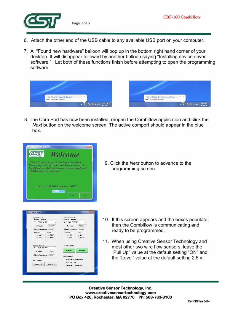
6. Attach the other end of the USB cable to any available USB port on your computer. 7. A “Found new hardware” balloon will pop up in the bottom right hand corner of your desktop. It will disappear followed by another balloon saying “Installing device driver software.” Let both of these functions finish before attempting to open the programming software.
Page 3 of 6
8. The Com Port has now been installed, reopen the Combiflow application and click the Next button on the welcome screen. The active comport should appear in the blue box.
9. Click the Next button to advance to the programming screen.
10. If this screen appears and the boxes populate, then the Combiflow is communicating and ready to be programmed. 11. When using Creative Sensor Technology and most other two wire flow sensors, leave the “Pull Up” value at the default setting “ON” and the “Level” value at the default setting 2.5 v.
Found new hardware Installing device driver software

Creative Sensor Technology, Inc. www.creativesensortechnology.com
PO Box 426, Rochester, MA 02770 Ph: 508-763-8100 Rev CBF Ins 0414
CBFCBF--100 Combiflow100 Combiflow
12. Under Input Sensor 1, select the model number of the CST flow sensor wired to the sensor 1 input terminals from the drop down menu. The K And Offset numbers will autofill. For other flow sensors, select other K & Offset and manually enter the numbers. 13. Repeat this procedure for Input Sensor 2. 14. The Output Sensor is the virtual sensor output to the controller. It combines the flow rates of the two inputs. It is usually set to the same size as one of the input sensors but may be a third size.
Page 4 of 6
15. If you change any setting, the green Program button will turn yellow indicating that a change has been made but not sent. Closing the programmer at this point will not change any programmed settings in the attached Combiflow.
16. When all data has been entered, click the yellow Program button to download the settings to the Combiflow. The button will turn pale while downloading and back to green when complete.
17. To review the settings programmed into the Combiflow, click the Refresh button. It will turn pale while the data is retrieved and the boxes repopulated, then back to green when complete.
18. The programmed values will be stored in the non-volatile memory of the Combiflow device.
19. The data may be saved on your computer as a txt file by clicking the Save File button. By saving the data, you can store these values for future reference or rapidly program other Combiflow devices by retrieving this information with the Open File button.
20. When finished, click the red X button in the top right corner to close the screen and then click the Close button to exit the programmer.
Creative Sensor Technology, Inc. www.creativesensortechnology.com
PO Box 426, Rochester, MA 02770 Ph: 508-763-8100 Rev CBF Ins 0414
CBFCBF--100 Combiflow100 Combiflow Page 5 of 6
The Combiflow is now programmed. Disconnect the USB cable. If the Combiflow has been programmed while installed in the field, don’t forget to reconnect the output pulse wiring before closing the cover.
Remember to match the flow input K & Offsets on your controller to the numbers programmed into the Combiflow for the Output Sensor.
Mounting Instructions The Combiflow Model 100 is mounted in an enclosure rated NEMA 6P and is supplied with watertight, compression type gland. While the enclosure is suitable for outdoor or below grade mounting, the preferred location is indoors or inside a controller pedestal. The enclosure may be attached to any flat surface, vertical or horizontal, using mechanical hardware or double sided adhesive tape. Consideration should be given to access the device for re-programming or service.
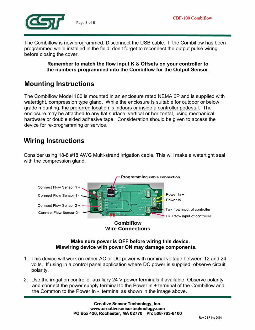
Wiring Instructions Consider using 18-8 #18 AWG Multi-strand irrigation cable. This will make a watertight seal with the compression gland.
Make sure power is OFF before wiring this device. Miswiring device with power ON may damage components.
1. This device will work on either AC or DC power with nominal voltage between 12 and 24
volts. If using in a control panel application where DC power is supplied, observe circuit polarity.
2. Use the irrigation controller auxiliary 24 V power terminals if available. Observe polarity and connect the power supply terminal to the Power in + terminal of the Combiflow and the Common to the Power In - terminal as shown in the image above.

Creative Sensor Technology, Inc. www.creativesensortechnology.com
PO Box 426, Rochester, MA 02770 Ph: 508-763-8100 Rev CBF Ins 0414
CBFCBF--100 Combiflow100 Combiflow
Page 6 of 6
Warranty Statement:
The Creative Sensor Technology Warranty Statement is available on our website under the About Us tab. Click this link or paste this address into your browser to view.
3. If auxiliary power terminals are not available, use a separate 24 VAC power supply. 4. Connect both sets of flow sensor leads to the terminal strip on the left as shown in the image on the preceding page.
5. Connect the pulse output terminals of the Combiflow to the flow input terminals of the controller, observing polarity. 6. Check all connections and power up the Combiflow. Only the Power LED will illuminate. 7. Make sure flow sensor calibration settings for Combiflow output match flow sensor set-up in irrigation controller. Check operation by flowing water through each flow sensor and observing indicated flow rate on controller. Compare with estimates calculated from number of sprinklers operating, pressure readings and nozzle sizes.