Embed Size (px)
Citation preview

CBE 30355 Transport Phenomena I Final Exam
December 13, 2011
Closed Books and Notes Problem 1). (30 points) A Variant on Hero's Fountain. a). Neglecting all frictional losses, what is the height hf of the fountain water jet? b). Modify your answer by accounting for the head losses in the pipes and fittings. Correlations for friction factors in pipes and fittings are given below. You may take the total length of pipe to be 120 cm of 1 cm ID tubing. You will probably need to do a couple of iterations to get the friction factor right. c). The result in part b leads to a rather unimpressive fountain. It is proposed to add a nozzle to the outlet to make it go higher. Nozzle friction factors are based on the ratio of areas of the inlet and outlet (! = small area/large area). While such factors are usually empirically measured, this one is easy to get analytically (Hint: think Bernoulli’s equation and mass balances!). Neglecting friction, derive the K factor of a nozzle as a function of !. d). If we use a nozzle with ! = 0.5, what is the new velocity (in the pipes) and fountain height? I just want an estimate: don’t re-compute the friction factor from part b!
h L = u 2
2 g ! K + 4 ff LD
u 2
2 g ff = 16
Re ; Re < 2100 ff ! 0.0791Re1 41 4
; 3000 < Re < 10 5
1ff
= 4.0 log 10 Re ff – 0.40 ; Re > 3000
Fitting K value
sudden contraction 0.45 sudden expansion 1.0
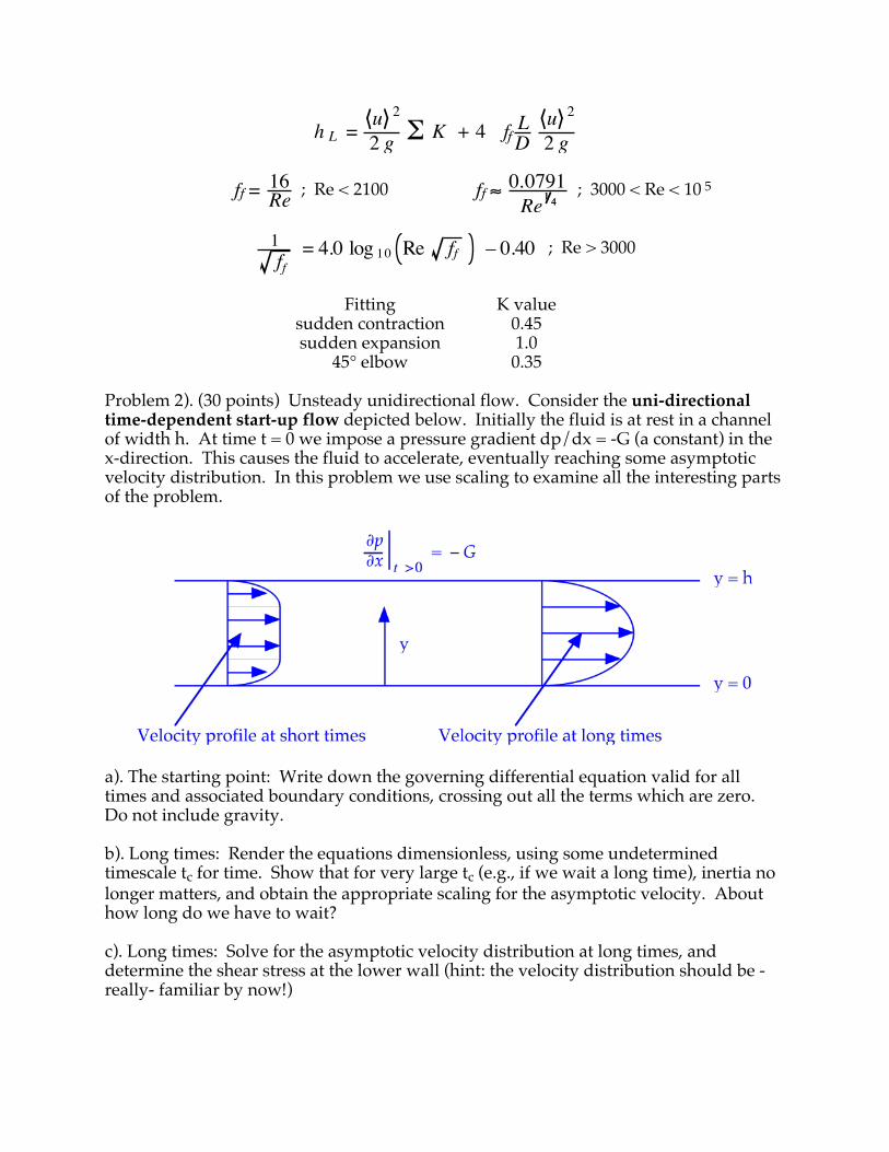
45° elbow 0.35 Problem 2). (30 points) Unsteady unidirectional flow. Consider the uni-directional time-dependent start-up flow depicted below. Initially the fluid is at rest in a channel of width h. At time t = 0 we impose a pressure gradient dp/dx = -G (a constant) in the x-direction. This causes the fluid to accelerate, eventually reaching some asymptotic velocity distribution. In this problem we use scaling to examine all the interesting parts of the problem.
a). The starting point: Write down the governing differential equation valid for all times and associated boundary conditions, crossing out all the terms which are zero. Do not include gravity. b). Long times: Render the equations dimensionless, using some undetermined timescale tc for time. Show that for very large tc (e.g., if we wait a long time), inertia no longer matters, and obtain the appropriate scaling for the asymptotic velocity. About how long do we have to wait? c). Long times: Solve for the asymptotic velocity distribution at long times, and determine the shear stress at the lower wall (hint: the velocity distribution should be -really- familiar by now!)
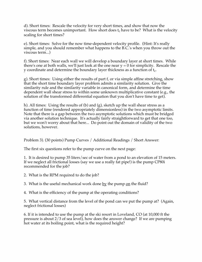
d). Short times: Rescale the velocity for very short times, and show that now the viscous term becomes unimportant. How short does tc have to be? What is the velocity scaling for short times? e). Short times: Solve for the now time-dependent velocity profile. (Hint: It's really simple, and you should remember what happens to the B.C.'s when you throw out the viscous term...) f). Short times: Near each wall we will develop a boundary layer at short times. While there's one at both walls, we'll just look at the one near y = 0 for simplicity. Rescale the y coordinate and determine the boundary layer thickness as a function of tc. g). Short times: Using either the results of part f, or via simple affine stretching, show that the short time boundary layer problem admits a similarity solution. Give the similarity rule and the similarity variable in canonical form, and determine the time dependent wall shear stress to within some unknown multiplicative constant (e.g., the solution of the transformed differential equation that you don't have time to get). h). All times: Using the results of (b) and (g), sketch up the wall shear stress as a function of time (rendered appropriately dimensionless) in the two asymptotic limits. Note that there is a gap between the two asymptotic solutions which must be bridged via another solution technique. It's actually fairly straightforward to get that one too, but we won't worry about that here... Do point out the domain of validity of the two solutions, however. Problem 3). (30 points) Pump Curves / Additional Readings / Short Answer: The first six questions refer to the pump curve on the next page: 1. It is desired to pump 35 liters/sec of water from a pond to an elevation of 15 meters. If we neglect all frictional losses (say we use a really fat pipe!) is the pump CP80i recommended for the job? 2. What is the RPM required to do the job? 3. What is the useful mechanical work done by the pump on the fluid? 4. What is the efficiency of the pump at the operating conditions? 5. What vertical distance from the level of the pond can we put the pump at? (Again, neglect frictional losses) 6. If it is intended to use the pump at the ski resort in Loveland, CO (at 10,000 ft the pressure is about 2/3 of sea level), how does the answer change? If we are pumping hot water at its boiling point, what is the required height?
Speci!cations are approximations only and are subject to change without notice. No reliance can be made on these approximationsJAN 2011
Technical Data
DIESEL/ELECTRIC DRIVE AUTO PRIME CONTRACTOR PUMP
Technical Data CP80iMaterials of ConstructionPump Casing: Suction Cover:Air Separation Tank:Bearing Bracket:Pump Shaft:Impeller:Wearplates:Mechanical Seal:N.R.V. (Ball Type):
Design DetailsPump Description
Suction Flange:Delivery Flange:Nominal Casing Thickness:Solids Handling Size:Operating Speed:Maximum Head:Maximum Capacity:
S.G. IRON 400/12S.G. IRON 400/12S.G. IRON 400/12S.G. IRON 400/12431 Stainless Steel316 Stainless Steel316 Stainless SteelSilicon Carbide/Silicon CarbideS.G. IRON 400/12
Single Stage, volute type, 3 blad-ed fully open Centrifugal pump80 mm80 mm10 mm38 mmMIN: 1400rpm MAX: 2400rpm28.5 m40 L/sec
Pumpset DimensionsWidth:Length:
900 mm1960 mm
Height:Dry Weight:
1300 mm840 kg
Fuel Consumption: 1.3 L/hr @ BEP 1400rpm WMRFuel Capacity: 160 litres, 24 hrs @ 2400rpm
7. For high Re flow past a bluff body, drag principally results from: A. Potential Flow B. Boundary Layer Separation C. Skin Friction D. Turbulence 8. Briefly describe one method for preventing stall on an aircraft wing. 9. Give a physical description of the Reynolds stress (e.g., where does it come from, and how is it defined?). 10. The turbulent friction velocity is a characteristic velocity created from a shear stress and fluid properties. What is it in terms of these parameters? 11. For a shear stress of 16 dynes/cm2 in the turbulent flow of water through a pipe, about how rough does the pipe wall have to be before it influences the flow? 12. Write down the Navier-Stokes equations in index notation. 13. Just as in the case of turbulent momentum transfer where we define a turbulent kinematic viscosity "t, so in the case of turbulent energy transfer we can define a turbulent thermal diffusivity #t. The turbulent Prandtl number is the ratio of these quantities (Prt = "t / #t). What is its approximate magnitude and why?

14. Provide two interpretations of !u~
.
15. The displacement thickness is defined as:
!* = 1 – u
U dy0
"
Provide a brief physical interpretation of this quantity.