Embed Size (px)
Citation preview

CB-7000 Utilities
User’s Manual
Revision 1A, July, 2001
© Copyright 2001

ii
CB-7000 UTILITIES.DOC
Trademark and Copyright InformationMeasurement Computing Corporation, InstaCal, Universal Library, and the Measurement Computing logo areeither trademarks or registered trademarks of Measurement Computing Corporation. Refer to the Copyrights &Trademarks section on mccdaq.com/legal for more information about Measurement Computing trademarks. Other product and company names mentioned herein are trademarks or trade names of their respectivecompanies.
© 2001 Measurement Computing Corporation. All rights reserved. No part of this publication may be reproduced, stored in a retrieval system, or transmitted, in any form by any means, electronic, mechanical, byphotocopying, recording, or otherwise without the prior written permission of Measurement ComputingCorporation.
NoticeMeasurement Computing Corporation does not authorize any Measurement Computing Corporation product for use in life support systems and/or devices without prior written consent from Measurement Computing Corporation. Life support devices/systems are devices or systems that, a) are intended for surgical implantation into the body, or b) support or sustain life and whose failure to perform can be reasonably expected to result in injury. Measurement Computing Corporation products are not designed with the components required, and are not subject to the testing required to ensure a level of reliability suitable for the treatment and diagnosis of people.

iii
Table of Contents
1 Connect Modules ......................................................................................................................11.1 Connect the First Module ..................................................................................................11.2 Connect the second module...............................................................................................4
2 CB-7000 Utility User Manual...................................................................................................82.1 Overview ............................................................................................................................82.2 Introduction .......................................................................................................................82.3 Package of 7000 Utility .....................................................................................................82.4 Installation of 7000 Utility.................................................................................................82.5 Uninstall the 7000 Utility ..................................................................................................92.6 Start the 7000 Utility .......................................................................................................102.7 Operation of 7000 Utility ................................................................................................12
2.7.1 Main Window of 7000 Utility ..................................................................................122.7.2 Stop Searching..........................................................................................................122.7.3 Assign COM Port, Baud Rate and Checksum for Searching ...................................132.7.4 Invoke Module Configuration Setting......................................................................132.7.5 Test for ALL Found Modules ..................................................................................152.7.6 Command Testing for a Module ..............................................................................162.7.7 .MAP File Operation ................................................................................................172.7.8 Change Baud Rate and Checksum ...........................................................................182.7.9 Exiting the 7000 Utility............................................................................................19
3 Dual Watchdog .......................................................................................................................203.1 Operating Principles ........................................................................................................203.2 Host Watchdog ................................................................................................................203.3 Module Watchdog ...........................................................................................................24
3.3.1 Introduction...............................................................................................................243.3.2 Frequent Module Reset Troubleshooting .................................................................26
3.4 Functions and Demo Programs.........................................................................................273.4.1 Host Watchdog Demo ..............................................................................................283.4.2 Communication Line Broken Detection...................................................................323.4.3 Module Watchdog ....................................................................................................32
4 Frequently Asked Questions...................................................................................................344.1 7000 FAQ ........................................................................................................................344.2 MISCELLANEOUS FAQ...............................................................................................354.3 Problem Reporting...........................................................................................................37

iv
This page is blank.

1
1 Connect Modules
1.1 Connect the First Module
Figure 1-1. Connect the first module

2
1. Connect the first module per Figure 1-1. (Replace the I-7012 module by the user’s firstmodule.) NOTE: Do not connect more than one module at a time.2. Install the 7000 Utility software from Disk. Please refer to Section 2, “7000 Utility UserManual”, in this manual.3. Run the 7000 Utility software to run a search for the user’s modules.
The 7000 Utility software will perform an auto search when started. If desired, click the icon to stop it. Refer to Figure 1-2.
Figure 1-2. Stop searching.
Click the menu item “COM Port” to select the COM port that the user will use. Select the baudrate 9600 and click the OK button. Refer to Figure 1-3.
Figure 1-3. Select the COM Port and Baud Rate.
After setting the configuration, click the icon to search again. Refer to Figure 1-4.

3
Figure 1-4. Search the Modules.
Every module has the same factory default setting as follows: address at 0x01, baud rate 9600,checksum disable. Refer to Figure 1-5. If the 70 00 Utility lists the module ID xxxx in t heinformation window, you have successfully connected to the first module and communicated withit. (Please do not connect more than one module at a time.)
Figure 1-5. The Default Setting of Module
4
1.2 Connect the second module
If you have two modules in the same RS-485 network and both modules have the same addressand baud rate; they will conflict with each other.
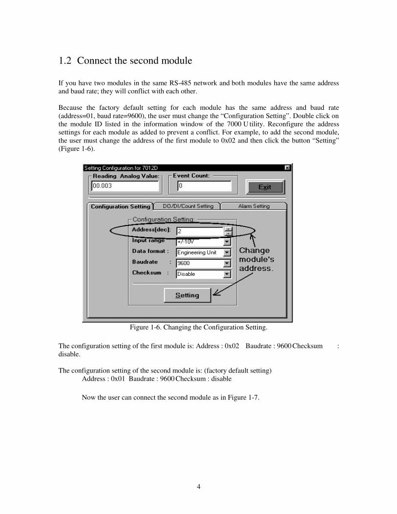
Because the factory default setting for each module has the same address and baud rate(address=01, baud rate=9600), the user must change the “Configuration Setting”. Double click onthe module ID listed in the information window of the 7000 U tility. Reconfigure the addresssettings for each module as added to prevent a conflict. For example, to add the second module,the user must change the address of the first module to 0x02 and then click the button “Setting”(Figure 1-6).
Figure 1-6. Changing the Configuration Setting.
The configuration setting of the first module is: Address : 0x02 Baudrate : 9600 Checksum :disable.
The configuration setting of the second module is: (factory default setting)Address : 0x01 Baudrate : 9600 Checksum : disable
Now the user can connect the second module as in Figure 1-7.

5
Figure 1-7. Connect the Second Module

6
Search for the connected module again. It will find two modules at address 0x01 and 0x02 asshown in Figure 1-8.
Figure 1-8. Found Two Modules at 0x01 and 0x02.
To connect more modules in the same RS-485 network, you must change the address to preventconflict. For example, the user can change the address 0x01 of second module to address 0x03.Now the module configuration would be as follows:Module 1: Address:0x02 Baudrate: 9600 Checksum: disabled.Module 2: Address:0x03 Baudrate: 9600 Checksum: disabled.
Next, connect the third module as shown in Figure 1-9. The configuration of the third module hasthe factory setting as follows:Module 3: Address:0x01 Baudrate: 9600 Checksum: disabled
The user can connect several modules one by one. The important thing is that the modules cannothave the same address and baud rate concurrently in the same RS-485 network.

7
Figure 1-9. Connect Modules.

8
2 CB-7000 Utility User Manual
2.1 OverviewThis section contains the following:• Introduction of 7000 Utility• Package of 7000 Utility• Installation of 7000 Utility• Uninstall the 7000 Utility• Start the 7000 Utility• Operation of 7000 Utility• Change baud rate and checksum• Exit the 7000 Utility
2.2 IntroductionThe 7000UTIL.EXE is a software utility for CB-7000 modules. It works in multiple baud rateenvironments to meet the specification of “Self-Tuner” of 7000 m odules. It provides thefollowing capabilities:
• Detection of CB-7000 modules connected to the Host PC.• Setting module configuration.• Executing data input and/or output for every connected CB-7000 module.• Saves the information for the detected CB-7000 modules into a file (with .map extension file
name).
Please refer to the following content to complete the installation procedure.
2.3 Package of 7000 UtilityThe 7000 Utility package includes a setup disk.
2.4 Installation of 7000 UtilityBefore installing, please confirm the following requirements are met:
• Microsoft Windows 95/98/NT 4.0 operation system.• 16 MB RAM Memory.• 10 MB hard disk available space.
Starting the Installation:
1. Insert the 7000 Utility setup disk into the disk drive.2. Click "Start" in the task bar, then click "Run".3. Enter "A: Setup.exe" as shown in Figure 2-1 (or whatever drive letter applies).4. Click “OK” to start the installation procedure.5. Follow the instructions in the installation procedures.

9
Figure 2-1. Install the 7000 Utility.
2.5 Uninstall the 7000 UtilityTo uninstall the 7000 Utility software, perform the following steps:
1. Invoke “Control Panel” as shown in Figure 2-2 .
Figure 2-2 Windows –Setting-Control Panel
2. Click the icon “Add/Remove Programs” in “Control Panel” as shown in Figure 2-3.3. Select item “7000UTIL” and click the button “Add/Remove…” to uninstall (Figure 2-4).

10
Figure 2-3. Double-click the Icon “Add/Remove Programs”.
Figure 2-4. 7000Util - Button to Uninstall the Software.
2.6 Start the 7000 UtilityTo start the 7000 UTILITY, select 7000Util in the Program Menu and click the “Start” in the taskbar (Figure 2-5).

11
Figure 2-5. Windows Program Menu.
When 7000UTIL.EXE is loading, a window displays to show the startup picture (Figure 2-6). Bydefault, the startup window will stay on about 3 seconds.
Figure 2-6. The startup picture.
During the startup time, the 7000 UTILITY will read the file ICPCON.CFG to get the COM port,baud rates and checksum information. After startup, the main window of 7000 UTILITY willcome on (there is more information in section 2-2). and start the searching process automatically.It reads COM po rt number, baud ra tes and checksum information. If it fails to read theICPCON.CFG (if for example, the information does not exi st), the default value for COM portis 2, baud rate speed of 9600 and checksum is enabled. This means that the searching processlimit is COM 2 and baud rate speed is 9600. When quitting the 7000U TIL.EXE, the selectedCOM port, baud rates and checksum are stored in ICPCON.CFG.

12
2.7 Operation of 7000 UtilityThis section describes all aspects of the 7000 utility software.
2.7.1 Main Window of 7000 Utility
The main window of 7000 Utility is shown in Figure 2-7. All operations of 7000 Utility are basedon the main window of Figure 2-7.
Figure 2-7. Main Window of 7000 Utility
2.7.2 Stop SearchingTo stop running the program:Initially, it will be in the searching process when starting the 7000Util.EXE. The user can stop thesearching process by clicking the Stop icon in the tool bar or any menu item (Figure 2-8).
Fig 2-8. Stop the searching process.

13
2.7.3 Assign COM Port, Baud Rate and Checksum for SearchingWhen the COM Port menu is clicked, a window titled “Select the COM port and Baud Rate…”will appear (Fig. 2-9). It prompts the user to assign the COM port, baud rate and checksum status.After assigning and clicking OK button, the 7000 Utility will start the searching process again.Any module that meets these conditions will be found and displayed in the information window.The values of COM port, baud rate and checksum are stored automatically in ICPCON.CFGwhen exiting the 7000 Utility.
Figure 2-9. Assign COM Port, Baud Rates and Checksum Status
2.7.4 Invoke Module Configuration SettingTo enter the module configuration, follow these steps:
1. Move the cursor to the desired module displayed in the information window.2. Double click to enter the module configuration setting.3. After double clicking, a configuration setting window displays. Adjust the configuration settingif desired.
For example, to set the module configuration of 7012, double clicking the 7012 information listas shown in Figure 2-10. A window t itled “Setting Configuration for 7012D” will be displayed(Figure 2-11).

14
Figure 2-10. Module Configuration Setting for CB-7012D.
Figure 2-11. The “Setting Configuration for 7012D” window.

15
If you wish to set the High/Low alarm, click the Alarm Setting tabbed page as shown inFigure 2-12 .
Figure 2-12 Alarm Setting Tabbed Page.
2.7.5 Test for ALL Found ModulesIn order to test that all “Found Out” modules are working properly, click on the menu item“Run”. And the window “7000 Module Running” will display as shown in Figure 2-13.
Figure 2-13 7000 Module Running Window.

16
2.7.6 Command Testing for a ModuleTo send and receive module commands, click on “Terminal”, then “Single Line” (Figure 2-14). Ifno module is selected, the default baud rate is 9600 and checksum is disabled as in Figure 2-15. Ifa module is selected, the baud rate and checksum status will be displayed as the selected moduleshown in Figure 2-16. Figure 2-17 shows a command sent to the selected module
Figure 2-14. Selected Module
Figure 2-15. No module is selected

17
Figure 2-16. A Module is Selected
Figure 2-17. Send a command to 7012
2.7.7 .MAP File OperationConfiguration information can be stored in a file with a .map extension file name (*.map). Thisfile can be opened or printed out. The menu item “Open/Save/Print” is shown in Figure 2-18.The operation to save the “All Found” modules in a file (e.g., test.map) is shown in Figure 2-19.Figure 2-20 shows opening a stored map file.

18
Figure 2-18. Open/Save/Print Menu and Tool Bar.
Figure 2-19. To Save a Map File test.map.
Figure 2-20. Opening a Map File test.map
2.7.8 Change Baud Rate and ChecksumBefore clicking on t he Setting button on the window “Setting Configuration for XXXX” tochange the baud rate or checksum, connect t he INIT* and GND t erminals of this module. SeeFigure 2-21. To change the baud rate or checksum:
1. Use wire to connect the INIT* and GND of this module (Figure 2-21).
Figure 2-21. Shorting “INIT*” and “(B) GND”.

19
2. Make the desired change(s).2.Click on the “Setting” button.3.The 7000 Utility displays the window as Figure 2-22. If the message “Please connect Init* toGND. Then Click OK button again!!!” is displayed, connect Init* terminal to the GND terminal.
Setting Configuration OK !!Please Turn off the power of 7000 module,then Turn On again to take effect the setting!!!
Figure 2-22. Setting Configuration OK!!
4. Turn OFF the power to this module and then turn it back ON. If an Error Code 17 message isdisplayed, it means a failure. Re-check the connection of INIT and GND of the module, andrepeat the above steps again.
2.7.9 Exiting the 7000 Utility
Please refer to Figure 2-23 to quit the 7000 Utility.
Figure 2-23. To Exit the 7000 Utility.
When exiting the 7000 Utility, a window will prompt you to exit as in Figure 2-24.
Figure 2-24. Make sure to exit 7000.
Please click “Yes” to exit the 7000 Utility.

20
3 Dual Watchdog
3.1 Operating Principles
All 7000 modules are equipped with a hardware module watchdog and software host watchdog.The 7000 series are designed for industrial applications. Therefore, they can work in a harshenvironment. However, there are often high-voltage transients in such environments. Themodules may go down if noise levels are too high. The built-in hardware module watchdog canreset the module if it is down for too large signal (refer to Figure 3-1). Sometimes even the host-PC may be down for hardware or software reasons. The software host watchdog will monitorthe status of host-PC. If the host-PC is down, a ll the outputs of 7000 modules will go to theirpredefined safe states. (Refer to Figures 3-2 to 3-3.)
If the RS-485 network is open, host commands cannot be sent to remote modules. This can bedangerous in some applications. To prevent a serious problem, the 7000 output modules willforce their outputs to pre-defined safe states if the host watchdog is active. This dual watchdogfeature increases the reliability of system as follows:
Dual watchdog = module watchdog + host watchdog
Host watchdog: (software)If the host is down, all module outputs go to a safe state (Safe value). See Figures 3-2 and 3-3
Module watchdog: (hardware)If the module is down, it resets the module; the output goes to a pre-determined Power-On value.(See Figures 3-4 and 3-5.
3.2 Host WatchdogThe host can go down for the following reasons:
Noise signals are too high. This causes host hardware to make errors.Software problem. This makes the host go to the dead-lock state.Hardware problem; host hardware is damaged.The RS485 network is open and can’t send out commands to modules.
The software host watchdog monitors the host computer. If the host computer is down, theoutput of the 7000 modules will automatically go to their safe states to avoid possibleprocess damage.
When the Host PC periodically sends command “~**”, it signals that the Host PC and wires areOK (Figure 3-3).
21
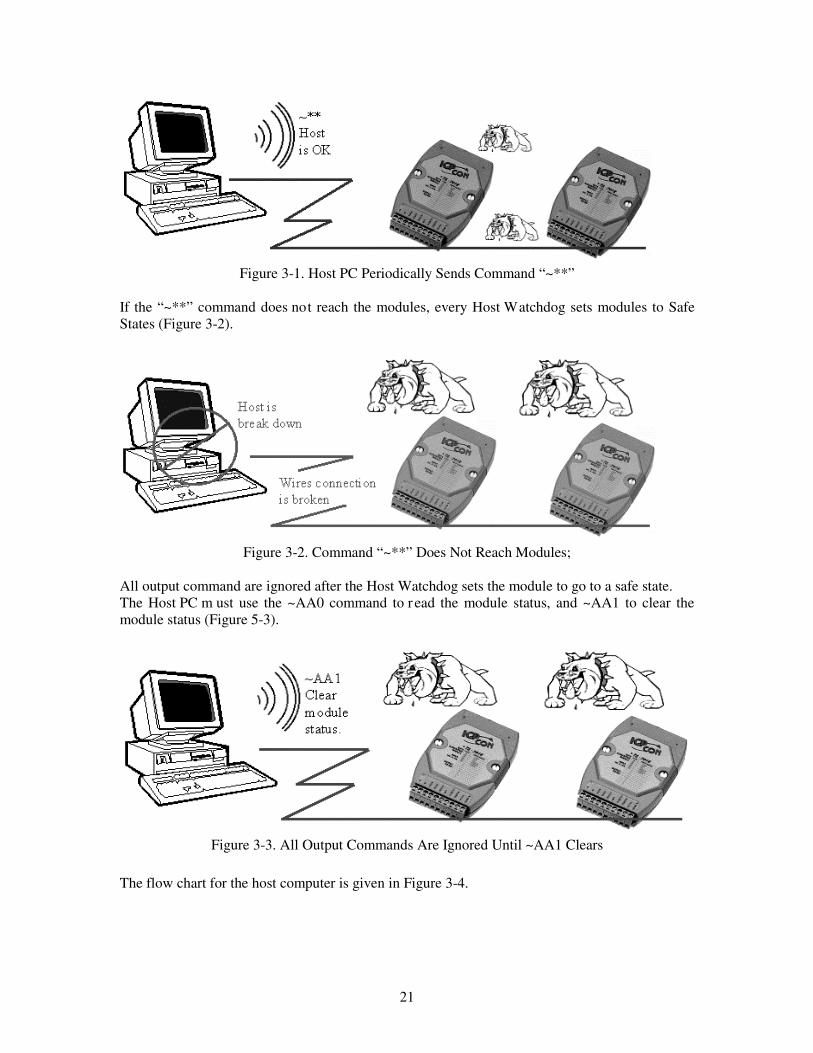
Figure 3-1. Host PC Periodically Sends Command “~**”
If the “~**” command does not reach the modules, every Host Watchdog sets modules to SafeStates (Figure 3-2).
Figure 3-2. Command “~**” Does Not Reach Modules;
All output command are ignored after the Host Watchdog sets the module to go to a safe state.The Host PC m ust use the ~AA0 command to r ead the module status, and ~AA1 to clear themodule status (Figure 5-3).
Figure 3-3. All Output Commands Are Ignored Until ~AA1 Clears
The flow chart for the host computer is given in Figure 3-4.

22
Figure 3-4. Flow chart of Host Watchdog.

23
Demo: host wat chdog and safe value for 7060, and refer to hardware manual for det ailedinformation.
01. Power on and run test.exe02. Press 203. Press $012Enter] Æ Receive=!0140060104. Press 205. Press #01000F[Enter] Æ Receive =>06. Press 207. Press $016[Enter] Æ Receive=!0F0F0008. Press 209. Press ~014S[Enter] Æ Receive=!0F0F0010. Press 211. Press ~01311E[Enter] Æ Receive=!0112. Wait 3 seconds; user will find that the LED of 7060 is flashing and the relay output is allOFF. This action simulates that the host computer has failed and the host watchdog is active. Allrelay outputs go to their safe states.13. Press 214. Press $016[Enter] Æ Receive=!01000F0015. Press 216. Press ~011[Enter] Æ Receive = !01
Note: The program “test.exe” is contained in the NAP7000S. It is a software utility of DOSversion for 7000 modules. Please contact us to get the detailed information of NAP7000Ssoftware package.
Step 03: This is a 7000 DIO module; baud rate=9600.Step 05: Set all the relay output to the ON State.Step 07: Read back the state of all DI/O: all relays ON, all inputs HIGHStep 09: Set current D/O states to safe-valueStep 11: Enable the host watchdog and timer = 1EH*0.1s = 3 sec.Step 14: Read back the DI/O state, all relays OFF, all inputs HIGH.Step 16: Clear the module status to 00

24
3.3 Module Watchdog3.3.1 IntroductionThe 7000 series modules are designed for industrial applications. They can b e used in anelectrically harsh environment. However, the module can go down if EMI or power supply noiseis too high.The “$AA5” command is designed to detect the module hardware watchdog timeout. If a modulegoes down, the module hardware watchdog circuit resets the module. The reset puts the outputstate of module to its power-on value. The Power-On value may be different from the output-value before module was reset. Therefore the user must send an output command again to returnto the original output state (or value) before module watchdog reset.
Figure 3-5. Module Watchdog Resets the Module When the Module is Halted.

25
The flow chart for module hardware watchdog failure detection is given in Figure 3-6.
Figure 3-6. Flow chart of Module Hardware Watchdog.
We recommend testing the m odule status frequently if the module is working in a harshenvironment.

26
3.3.2 Frequent Module Reset TroubleshootingIf the user ’s module has been reset frequently, it may be occur ring because of the followingreasons:1. Noise levels are too high.The 7000 series modules are designed for industrial applications. They can be used in a harshenvironment. There is often high electrical noises or RF energy transients in such an environment.Therefore, the module may go down if these noise sources is too high.
The user can improve the stability and r eliability of applications by reducing noise after themodule has been reset. The Power-On value may be not appr opriate or may even be dangerousfor the user’s application. Thus, the user must send the desired output value again.
Table 3-1. Comparison of Host Watchdog and Module Watchdog
Host Watchdog Module WatchdogSoftware orHardware
Software WatchdogBuilt in firmware
Hardware WatchdogCircuit in module
Purpose Monitor the Host PCUse in all output modules
Monitor the Module;Used in all modules
When to occurs Host is downCommunication line is broken
Module is hungNoise is too high
What to do Module go to safe stateModule status S = 0x04Module’s output go to safe valueAll output command are ignored.
Reset the ModuleModule Reset status S = 1Module’s output go to PowerOnvalue
CLEAR module-status
~AA1S is set to 0
READ module-status ~AA0S = 4 Î Host is downS = 0 Î Host is OK
READ and RESETmodule-reset –status
$AA5S = 1 Î Module ResetS = 0 Î Not reset
Setup steps Setup the safe valueSetup the timer interval value ofHost Watchdog and en able theHost Watchdog
Setup the PowerOn value
Send “Host is OK” ~**Send this command to modulesbefore timeout intervals expired ofHost Watchdog’s timer.

27
3.4 Functions and Demo ProgramsThere are several functions provided for Watchdog security. For det ailed information of thesefunctions, please refer to user manual of NAP7000P. These functions are listed as following:
HostIsOK: To signal modules "Host is OK", send "~**".ReadModuleResetStatus: To read the module reset status.ToSetupHostWatchdog: To setup the module's Host Watchdog.ToReadHostWatchdog: To read the module's Host Watchdog setup values.ReadModuleHostWatchdogStatus: To read the module's Host Watchdog status.ResetModuleHostWatchdogStatus: Reset the module's Host Watchdog status.SetSafeValueForDo: To setup the safe value for DO modules.SetPowerOnValueForDo: To setup the power on value for DO modules.SetSafeValueForAo: To setup the safe value for AO modules.SetPowerOnValueForAo: To setup the power on value for AO modules.SetPowerOnSafeValue: To setup the power on and safe value for modules.
There are some Demo Programs for the Watchdog demo. They are written in VB, Delphi, BCBcomputer languages, and placed in the demo folders of these languages. These demo programsare as follows:
SafeAI: Host Watchdog and Safe value demo for analog input modules.
SafeAO: Host Watchdog and Safe value demo for analog output modules.
SafeDO: Host Watchdog and Safe value demo for digital output modules.
Watchdog: Host Watchdog and Module Watchdog demo.
The user can find these functions and Demo Programs in NAP7000P version 3.3 . Pleasecontact us to get the detailed information about NAP7000P software package.
Descriptions of Watchdog Demo
Platform: Windows 95/98/NTSoftware : NAP7000P v3.30 (or above)Demo Program: NAP7000P\Demo\Delphi\Watchdog\Project1.dpr
NAP7000P\Demo\BCB\Watchdog\Project1.bpr NAP7000P\Demo\VB\Watchdog\Project1.vbp
Modules: 7520 x 1 (RS-232 / RS-485) 70xx x 1 (recommend to use a output module)Module Configuration:Baud rate: 9600Checksum: disableAddress: 0x01
This program demonstrates the following features:Host Watchdog.
28
Communication line broken detection.Module Watchdog.
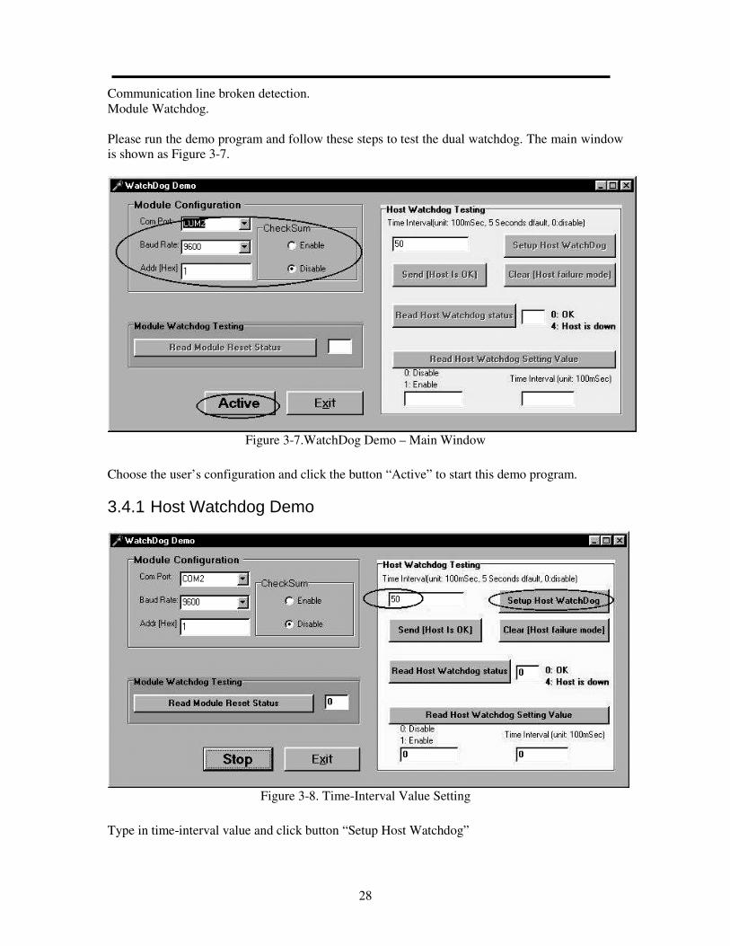
Please run the demo program and follow these steps to test the dual watchdog. The main windowis shown as Figure 3-7.
Figure 3-7.WatchDog Demo – Main Window
Choose the user’s configuration and click the button “Active” to start this demo program.
3.4.1 Host Watchdog Demo
Figure 3-8. Time-Interval Value Setting
Type in time-interval value and click button “Setup Host Watchdog”

29
Figure 3-9. After Setting Up the Host Watchdog
Figure 3-9 shows that the user can read the status and the setting value of Host Watchdog. Theuser got these values:• 0:Host is OK,• 1:Host Watchdog is Enabled,• Host Watchdog time interval is 5 seconds.
Figure 3-10. Host Watchdog Demo.
After 5 seconds, the system displays a message that the “Host is down!!!” (Figure 3-10).Click the button “OK” to close this message box.
Since the Host Watchdog is enabled, if the Host PC does not send the command ~** to module,the module ignores all other output commands and the module output stays in the safe state(Figure 3-11).After the module goes to the safe state, the module’s Host Watchdog is disabled automatically.Click on the button “Clear [Host failure mode]” to clear this status (see Figure 3-11). The modulestatus will return to “0:Host is OK!”.

30
Figure 3-11. Host Down and Module Goes to Safe State.
Figure 3-12. Host Setup Message
The Host Watchdog is disabled after the module goes to the safe state. Thus, the user must setupthe Host Watchdog again (Figure 3-12). Following this, the module status returns to “0:Host isOK!” (Figure 3-13).

31
Figure 3-13. Host is OK (Status 0)
Normally, the host should send a [Host is OK] command every second.When the module status is “0:OK” and Host Watchdog is enabled. Click on the button “Send[Host is OK]” every 1 second. Note that after 5 seconds has past, the message box “Host is down”is not displayed since the user sent the command ~** to the module signaling the module that theHost is alive and well.
Type in 0 in the Host Watchdog’s time interval edits box. And click the button “Setup HostWatchdog” to disable it (Figure 3-14).
Figure 3-14. Setup to Disable Host WatchDog

32
3.4.2 Communication Line Broken Detection
Normally, the Module Reset Status is 0 (Figure 3-15). As a t est, disconnect the RS-232 cablefrom a 7520 module, simulating a broken communication line. A message displays indicating thatthe communication line is broken between computer and module (Figure 3-16).
).Figure 3-15. Normal Module Reset Status
Figure 3-16. Module Status - Communication line is broken.
Click button “OK” to close it. (This feature doesn’t involve the Dual Watchdog.)
3.4.3 Module Watchdog
Please connect the RS-232 cable to the 7520 module again. Unplug the module and then plug itagain. A “Reset” message box (Figure 3-17) is displayed.

33
Figure 3-17. Module Reset Message Box
Module has been reset; its output went to the PowerOn value. Click the button “OK” to close it.
The PowerOn v alue may be not app ropriate or even dangerous for the user’s application.Therefore, you should send the correct output value again to ensure safe operation.

34
4 Frequently Asked Questions
4.1 7000 FAQQ: How is the checksum computed?
A: The steps to compute checksum are as following:Step 1: Checksum=0;Step 2: For overall command byte with index, do this loop: Checksum = Checksum + Command byte [index]
Step 3: Checksum = Checksum & 0xffStep 4: Convert checksum to ASCII high byte and ASCII low byteFor example,Command = $012[Enter]Checksum = '$'+'0'+'1'+'2' = 0x24+0x30+0x31+0x32 = 0xB7Checksum & 0xff = 0xB7Checksum high byte = 'B'Checksum low byte = '7'Command with checksum = $012B7[Enter]
Q: When to do I use a repeater in the RS-485 network?
A: The us er should use repeater when the network has m ore than 256 m odules, or it is over1.2 km long.
Q: What is the maximum scan rate in the RS-485 network?
A: The s can rate depends on t he baud rate of RS-232 COM port, checksum status, modulenumbers, channels, command to send, result string that received and system performance.• For the environment to test:• 7012 module: x 1• Channel: x 1• Baud Rate: 115200 bps• Command: #AA (cr)(null) ==> 5 Chars• Result: >SDDDDDD (cr) ==> 9 Chars
• 1 Char: 1 Start bit + 8 Data bits + 1 Stop bit = 10 bits• Every communications: Command string + Result string• = 14 Chars = 140 bits• 140 (bits/communication) / 115200 (bits/sec)• = 0.00122 (sec/communication)• Hardware delays (every communications): 1 ms• Scan rate: 1/ (0.00122 + 0.001) = 450 (communication/sec)• Estimated scan rate:• 450 times/sec maximum.• Tested value of scan rate:• 440 times/sec maximum without system message processing.• 360 times/sec maximum with system message processing.

35
Note: System message processing lets the OS process other tasks. This may affect theperformance of this program.
4.2 MISCELLANEOUS FAQ
Q: Error message "[LinkerError] Unresolved external 'xxxx_xxxx __stdcall' referenced fromxxxxxxxxxx “ with Borland C++ BuilderQ: Error message "xxxx.obj : error LNK2001: unresolved external symbol "xxxxxxxxxxx"(?xxxxx@@xxxxx)” with Microsoft Visual C++
A: Code will generate this error message if it references something (like a function, variable, orlabel) that the linker can't find in all the libraries and object files it searches. In general, there aretwo reasons this error occurs:1. What the code asks for doesn't exist (the symbol is spelled incorrectly or uses the wrong case)2. What the code asks for the wrong thing (e.g., the user is using mixed versions of the libraries—some from one version of the product, others from another version).
Otherwise, the naming conventions are different between C and C++, because of C++ decorationof external symbols. The different naming conventions may also cause the error message occurs.By causing C++ to drop name decoration, the extern "C" syntax makes it p ossible for a C ++module to share data and routines with other languages.
The most of the DLL files of our products are written in Microsoft Visual C++ 4.0/5.0, and usesthe C naming conventions. Thus, if the user’s program is in C++ syntax, the header file must beas follows:
#define EXPORTS extern "C" __declspec (dllimport)EXPORTS WORD CALLBACK xxxxx_GetDriverVersion(WORD *wDriverVersion);
These declarations force the compiler to use the C naming conventions to refer to these functions.
The user must not change the naming convention if the code is in C syntax. Thus, the header filemust be like the following:
#define EXPORTSEXPORTS WORD CALLBACK xxxxx_GetDriverVersion(WORD *wDriverVersion);
A few of the DLL files of our products use the C++ naming conventions. Thus, the user’sprogram must use the C++ syntax and the user must not change the naming conventions. Thus,the header file must be as follows:
#define EXPORTSEXPORTS WORD CALLBACK xxxxx_GetDriverVersion(WORD *wDriverVersion);
We will unify the naming conventions of overall DLL files of o ur products by C nam ingconventions to reduce these problems.

36
Note: If using the Microsoft Visual C++ for development tools, be sure to use the parameters -Tcor -TC with the VC compiler with C syntax. Use the parameters -Tp or -TP with the VC compilerwith C++ syntax.
Q: Why doesn’t ComboBox's CHANGE event work with VB?
A: In Delphi and Borland C++ Builder, the CHANGE event can work correctly when the userchooses the items. But, In Visual Basic, this event only occurs when the user keys in something.The user can write codes in event “CLICK” with Visual Basic to do the same work. This event“CLICK” also works correctly in Delphi and Borland C++ Builder.
Q: Is TIMER event reentered?
A: If the user uses object “TIMER” in the project, the user must ensure the setting value ofInterval of “TIMER” is appropriate to the user’s program, system and hardware.
Suppose the “TIMER” triggers an event to do something, and then triggers another event again todo the same work before the prior job does not done. This may cause the job to be reenteredconcurrently. In time, it may crash the user’s system since when many jobs are reentered at thesame time, the system is overload.
To prevent the system crash with the object “TIMER”, the suggestion is to av oid the reentry ofthe TIMER event as follows:
bool bProcessing ; // declare a flagvoid __fastcall TForm1::FormCreate(TObject *Sender){ bProcessing = false; }void __fastcall TForm1::Timer1Timer(TObject *Sender){ if (bProcessing == true)return ; // avoid reenterelsebProcessing = true;................................................// if (something wrong ) {//bProcessing = false; // enable next timer event to enter//return;//}................................................bProcessing = false; // enable next timer event to enter}
Q: Error message "Unable to create process" occurs with Borland C++ Builder and Delphi. Why?
A: This error message occurs when some .DLL file can't be found in the user’s system. Pleasemake the executable file of this program and then run the execution file. The user may receive adifferent error message as follows:

37
Error Title: Error Starting ProgramError Message: A required .DLL file, XXXX.DLL, was not found.The user can know what .DLL files are missing. Copying the specific .DLL files into the systemfolder of Windows will solve this problem. In general, the system folder is:C:\Windows\system (for Windows 95/98)Or C:\WinNT\System32 (for Windows NT)
The user might check the setting of Windows to find the system folder.
4.3 Problem Reporting
Technical support is available at no charge as described below. A good way to report problems isto send electronic mail to
When reporting problems, please include the following information:
Is the problem reproducible? If so, how?What kind and v ersion of Op eration System is t he user running? For example, Windows 3.1,Windows for Workgroups, Windows NT 4.0, etc.What kind of our products is the user using? Please refer to the product catalog.If a dialog box with an error message was displayed, please include the full text of the dialog box,including the text in the title bar.If the prob lem involves other programs or har dware devices, what devices or version of thefailing programs that the user using?Other comments relative to this problem or any suggestions will be helpful.
After we received your comments, we will reply as soon as possible. Please verify that you havereceived our comments.

38
For Your Notes.

EC Declaration of Conformity
We, Measurement Computing Corporation, declare under sole responsibility that the product:
CB-7000 Utilities Utility software for CB 7000 series modulesPart Number Description
to which this declaration relates, meets the essential requirements, is in conformity with, and CE markinghas been applied according to the relevant EC Directives listed below using the relevant section of thefollowing EC standards and other informative documents:
EU EMC Directive 89/336/EEC: Essential requirements relating to electromagnetic compatibility.
EU 55022 Cla ss B: Limits and methods of m easurements of radio interference characteristics ofinformation technology equipment.
EN 50082-1: EC generic immunity requirements.
IEC 801-2: Electrostatic discharge requirements for industrial process measurement and controlequipment.
IEC 801-3: Radiated electromagnetic field requirements for industrial process measurements and controlequipment.
IEC 801-4: Electrically fast transients for industrial process measurement and control equipment.
Carl Haapaoja, Director of Quality Assurance

Measurement Computing Corporation 10 Commerce Way
Suite 1008 Norton, Massachusetts 02766
(508) 946-5100Fax: (508) 946-9500
E-mail: [email protected]