Embed Size (px)
Citation preview
09 21 16.23/NGC
®
Cavity Shaftwall Systems
12TH EDITION
09
21
16
.23
123
124 CAVITY SHAFTWALL SYSTEMS
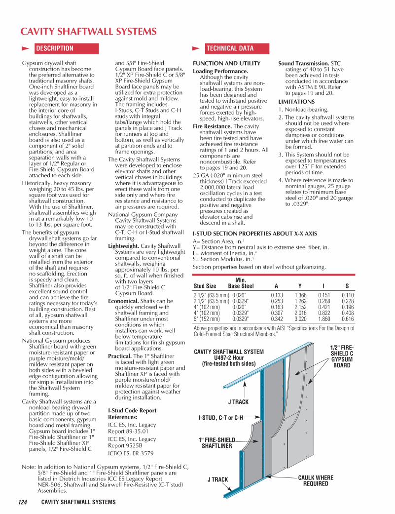
J TRACK
I-STUD, C-T or C-H
1" FIRE-SHIELDSHAFTLINER
J TRACK
1/2" FIRE-SHIELD CGYPSUMBOARD
CAVITY SHAFTWALL SYSTEMU497-2 Hour
(fire-tested both sides)
CAVITY SHAFTWALL SYSTEMS
DESCRIPTION TECHNICAL DATA
Min.Stud Size Base Steel A Y I S
2 1/2" (63.5 mm) 0.020" 0.133 1.366 0.151 0.1102 1/2" (63.5 mm) 0.0329" 0.253 1.262 0.288 0.2284" (102 mm) 0.020" 0.163 2.152 0.421 0.1964" (102 mm) 0.0329" 0.307 2.016 0.822 0.4086" (152 mm) 0.0329" 0.342 3.020 1.860 0.616
Above properties are in accordance with AISI “Specifications For the Design ofCold-Formed Steel Structural Members.”
I-STUD SECTION PROPERTIES ABOUT X-X AXISA= Section Area, in.2
Y= Distance from neutral axis to extreme steel fiber, in.I = Moment of Inertia, in.4
S= Section Modulus, in.3
Section properties based on steel without galvanizing.
Gypsum drywall shaftconstruction has becomethe preferred alternative totraditional masonry shafts.One-inch Shaftliner boardwas developed as alightweight, easy-to-installreplacement for masonry inthe interior core ofbuildings for shaftwalls,stairwells, other verticalchases and mechanicalenclosures. Shaftliner board is also used as acomponent of 2" solidpartitions, and areaseparation walls with alayer of 1/2" Regular orFire-Shield Gypsum Boardattached to each side.
Historically, heavy masonryweighing 20 to 45 lbs. persquare foot was used forshaftwall construction.With the use of Shaftliner,shaftwall assemblies weighin at a remarkably low 10to 13 lbs. per square foot.
The benefits of gypsumdrywall shaft systems go farbeyond the difference inweight alone. The corewall of a shaft can beinstalled from the exteriorof the shaft and requires no scaffolding. Erection is speedy and clean.Shaftliner also providesexcellent sound controland can achieve the fireratings necessary for today’sbuilding construction. Bestof all, gypsum shaftwallsystems are moreeconomical than masonryshaft construction.
National Gypsum producesShaftliner board with greenmoisture-resistant paper orpurple moisture/mold/mildew resistant paper onboth sides with a bevelededge configuration allowingfor simple installation intothe Shaftwall Systemframing.
Cavity Shaftwall systems are anonload-bearing drywallpartition made up of twobasic components, gypsumboard and metal framing.Gypsum board includes 1"Fire-Shield Shaftliner or 1"Fire-Shield Shaftliner XPpanels, 1/2" Fire-Shield C
and 5/8" Fire-ShieldGypsum Board face panels.1/2" XP Fire-Shield C or 5/8"XP Fire-Shield GypsumBoard face panels may beutilized for extra protectionagainst mold and mildew.The framing includes I-Studs, C-T Studs and C-Hstuds with integraltabs/flange which hold thepanels in place and J Trackfor runners at top andbottom, as well as verticallyat partition ends and toframe openings.
The Cavity Shaftwall Systemswere developed to encloseelevator shafts and othervertical chases in buildingswhere it is advantageous toerect these walls from oneside only and where fireresistance and resistance toair pressures are required.
National Gypsum CompanyCavity Shaftwall Systemsmay be constructed with C-T, C-H or I-Stud shaftwallframing.
Lightweight. Cavity ShaftwallSystems are very lightweightcompared to conventionalshaftwalls, weighingapproximately 10 lbs. persq. ft. of wall when finishedwith two layers of 1/2" Fire-Shield CGypsum Board.
Economical. Shafts can bequickly enclosed with shaftwall framing andShaftliner under mostconditions in whichinstallers can work, wellbelow temperaturelimitations for finish gypsumboard applications.
Practical. The 1" Shaftliner is faced with light greenmoisture-resistant paper andShaftliner XP is faced withpurple moisture/mold/mildew resistant paper forprotection against weatherduring installation.
I-Stud Code ReportReferences:ICC ES, Inc. Legacy Report 89-35.01ICC ES, Inc. Legacy Report 9525BICBO ES, ER-3579
FUNCTION AND UTILITYLoading Performance.
Although the cavityshaftwall systems are non-load-bearing, this Systemhas been designed andtested to withstand positiveand negative air pressureforces exerted by high-speed, high-rise elevators.
Fire Resistance. The cavityshaftwall systems havebeen fire tested and haveachieved fire resistanceratings of 1 and 2 hours. Allcomponents arenoncombustible. Refer to pages 19 and 20.
25 GA (.020" minimum steelthickness) J Track exceeded2,000,000 lateral loadoscillation cycles in a testconducted to duplicate thepositive and negativepressures created aselevator cabs rise anddescend in a shaft.
Sound Transmission. STC ratings of 40 to 51 havebeen achieved in testsconducted in accordancewith ASTM E 90. Refer to pages 19 and 20.
LIMITATIONS1. Nonload-bearing.2. The cavity shaftwall systems
should not be used whereexposed to constantdampness or conditionsunder which free water canbe formed.
3. This System should not beexposed to temperatures over 125˚ F for extendedperiods of time.
4. Where reference is made tonominal gauges, 25 gaugerelates to minimum basesteel of .020" and 20 gaugeto .0329".
CAULK WHEREREQUIRED
Note: In addition to National Gypsum systems, 1/2" Fire-Shield C,5/8" Fire-Shield and 1" Fire-Shield Shaftliner panels arelisted in Dietrich Industries ICC ES Legacy Report NER-506, Shaftwall and Stairwell Fire-Resistive (C-T stud)Assemblies.
125CAVITY SHAFTWALL SYSTEMS
09
21
16
.23
09 21 16.23 /NGC
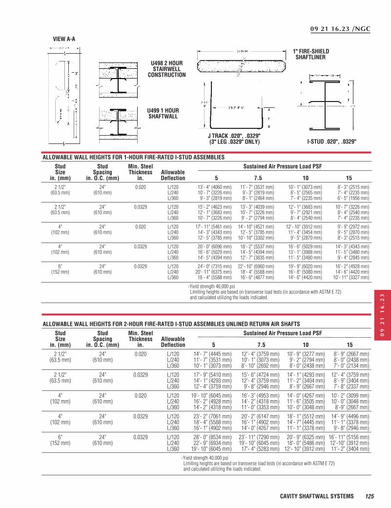
U498 2 HOURSTAIRWELL
CONSTRUCTION
1" FIRE-SHIELDSHAFTLINER
J TRACK .020", .0329"(3" LEG .0329" ONLY)
VIEW A-A
I-STUD .020", .0329"
U499 1 HOURSHAFTWALL
ALLOWABLE WALL HEIGHTS FOR 1-HOUR FIRE-RATED I-STUD ASSEMBLIES
Stud Stud Min. Steel Sustained Air Pressure Load PSFSize Spacing Thickness Allowable
in. (mm) in. O.C. (mm) in. Deflection 5 7.5 10 152 1/2" 24" 0.020 L/120 13'- 4" (4060 mm) 11'- 7" (3531 mm) 10'- 1" (3073 mm) 8'- 3" (2515 mm)
(63.5 mm) (610 mm) L/240 10'- 7" (3226 mm) 9'- 3" (2819 mm) 8'- 5" (2565 mm) 7'- 4" (2235 mm)L/360 9'- 3" (2819 mm) 8'- 1" (2464 mm) 7'- 4" (2235 mm) 6'- 5" (1956 mm)
2 1/2" 24" 0.0329 L/120 15'- 2" (4623 mm) 13'- 3" (4039 mm) 12'- 1" (3683 mm) 10'- 7" (3226 mm)(63.5 mm) (610 mm) L/240 12'- 1" (3683 mm) 10'- 7" (3226 mm) 9'- 7" (2921 mm) 8'- 4" (2540 mm)
L/360 10'- 7" (3226 mm) 9' - 2" (2794 mm) 8'- 4" (2540 mm) 7'- 4" (2235 mm)
4" 24" 0.020 L/120 17'- 11" (5461 mm) 14'- 10" (4521 mm) 12'- 10" (3912 mm) 9'- 9" (2972 mm)(102 mm) (610 mm) L/240 14'- 3" (4343 mm) 12'- 5" (3785 mm) 11'- 4" (3454 mm) 9'- 5" (2870 mm)
L/360 12'- 5" (3785 mm) 10'- 10" (3302 mm) 9'- 5" (2870 mm) 8'- 3" (2515 mm)
4" 24" 0.0329 L/120 20'- 0" (6096 mm) 18'- 2" (5537 mm) 16'- 6" (5029 mm) 14'- 3" (4343 mm)(102 mm) (610 mm) L/240 16'- 6" (5029 mm) 14'- 5" (4394 mm) 13'- 1" (3988 mm) 11'- 5" (3480 mm)
L/360 14'- 5" (4394 mm) 12'- 7" (3835 mm) 11'- 5" (3480 mm) 9'- 4" (2845 mm)
6" 24" 0.0329 L/120 24'- 0" (7315 mm) 22'- 10" (6960 mm) 19'- 9" (6020 mm) 16'- 2" (4928 mm)(152 mm) (610 mm) L/240 20'- 11" (6375 mm) 18'- 4" (5588 mm) 16'- 8" (5080 mm) 14'- 6" (4420 mm)
L/360 18 - 4" (5588 mm) 16'- 0" (4877 mm) 14'- 6" (4420 mm) 10'- 11" (3327 mm)
ALLOWABLE WALL HEIGHTS FOR 2-HOUR FIRE-RATED I-STUD ASSEMBLIES UNLINED RETURN AIR SHAFTS
Stud Stud Min. Steel Sustained Air Pressure Load PSFSize Spacing Thickness Allowable
in. (mm) in. O.C. (mm) in. Deflection 5 7.5 10 15
2 1/2" 24" 0.020 L/120 14'- 7" (4445 mm) 12'- 4" (3759 mm) 10'- 9" (3277 mm) 8'- 9" (2667 mm)(63.5 mm) (610 mm) L/240 11'- 7" (3531 mm) 10'- 1" (3073 mm) 9'- 2" (2794 mm) 8'- 0" (2438 mm)
L/360 10'- 1" (3073 mm) 8'- 10" (2692 mm) 8'- 0" (2438 mm) 7'- 0" (2134 mm)
2 1/2" 24" 0.0329 L/120 17'- 9" (5410 mm) 15'- 6" (4724 mm) 14'- 1" (4293 mm) 12'- 4" (3759 mm)(63.5 mm) (610 mm) L/240 14'- 1" (4293 mm) 12'- 4" (3759 mm) 11'- 2" (3404 mm) 8'- 9" (3404 mm)
L/360 12'- 4" (3759 mm) 9'- 8" (2946 mm) 8'- 9" (2667 mm) 7'- 8" (2337 mm)
4" 24" 0.020 L/120 19'- 10" (6045 mm) 16'- 3" (4953 mm) 14'- 0" (4267 mm) 10'- 2" (3099 mm)(102 mm) (610 mm) L/240 16'- 2" (4928 mm) 14'- 2" (4318 mm) 11'- 6" (3505 mm) 10'- 0" (3048 mm)
L/360 14'- 2" (4318 mm) 11'- 0" (3353 mm) 10'- 0" (3048 mm) 8'-9" (2667 mm)
4" 24" 0.0329 L/120 23'- 2" (7061 mm) 20'- 2" (6147 mm) 18'- 1" (5512 mm) 14'- 9" (4496 mm)(102 mm) (610 mm) L/240 18'- 4" (5588 mm) 16'- 1" (4902 mm) 14'- 7" (4445 mm) 11'- 1" (3378 mm)
L/360 16'- 1" (4902 mm) 14'- 0" (4267 mm) 11'- 1" (3378 mm) 9'- 8" (2946 mm)
6" 24" 0.0329 L/120 28'- 0" (8534 mm) 23'- 11" (7290 mm) 20'- 9" (6325 mm) 16'- 11" (5156 mm)(152 mm) (610 mm) L/240 22'- 9" (6934 mm) 19'- 10" (6045 mm) 18'- 0" (5486 mm) 12'-10" (3912 mm)
L/360 19'- 10" (6045 mm) 17'- 4" (5283 mm) 12'- 10" (3912 mm) 11'- 2" (3404 mm)›Yield strength 40,000 psiLimiting heights are based on transverse load tests (in accordance with ASTM E 72) and calculated utilizing the loads indicated.
›Yield strength 40,000 psiLimiting heights are based on transverse load tests (in accordance with ASTM E 72) and calculated utilizing the loads indicated.
126 CAVITY SHAFTWALL SYSTEMS
ALLOWABLE WALL HEIGHTS FOR 2-HOUR FIRE-RATED I-STUD ASSEMBLIES
Stud Stud Min. Intermittent Air Pressure Load PSFSize Spacing Steel Allowable
in. (mm) in. O.C. (mm) Thickness-in. Deflection 5 7.5 10 15
2 1/2 24 0.020 L/120 15'- 3"f (4648 mm) 12'- 6"f (3810 mm) 10'- 9"f (3276 mm) 8'-10"f (2692 mm)(63.5 mm) (610 mm) L/240 12'- 6" (3810 mm) 11'- 0" (3352 mm) 10'- 0" (3048 mm) 8'- 9" (2667 mm)
L/360 11'- 0" (3352 mm) 9'- 6" (2895 mm) 8'- 8" (2641 mm) 7'- 7" (2311 mm)
2 1/2 24 0.0329 L/120 17'-10" (5435 mm) 15'- 8" (4775 mm) 14'- 2"f (4318 mm) *12'- 5" (3784 mm)(63.5 mm) (610 mm) L/240 14'- 2" (4318 mm) 12'- 5" (3784 mm) 11'- 4" (3454 mm) 9'-10" (2997 mm)
L/360 12'- 5" (3784 mm) 10'-11" (3327 mm) 9'-10" (2997 mm) 8'- 7" (2616 mm)
4 24 0.020 L/120 20'- 4" (6197 mm) 16'- 8"f (5080 mm) *14'- 5"f (4394 mm) *11'-10"f (3606 mm)(102 mm) (610 mm) L/240 16'- 1" (4902 mm) 14'- 1" (4292 mm) 12'-10" (3911 mm) *11'- 2" (3403 mm)
L/360 14'- 1" (4292 mm) 12'- 4" (3759 mm) 11'- 2" (3403 mm) * 9'-10" (2997 mm)
4 24 0.0329 L/120 21'-10" (4114 mm) *19'- 1" (5816 mm) *17'- 4" (5283 mm) *15'- 1" (4597 mm)(102 mm) (610 mm) L/240 17'- 4" (5283 mm) 15'- 1" (4597 mm) 13'-10" (4216 mm) *12'- 0" (3657 mm)
L/360 15'- 1" (4597 mm) 13'- 2" (4013 mm) 12'- 0" (3657 mm) *10'- 6" (3200 mm)
6 24 0.0329 L/120 25'- 4" (7721 mm) *22'- 1" (6731 mm) *20'- 1" (6121 mm) *17'- 6" (5334 mm)(152 mm) (610 mm) L/240 20'- 1" (6121 mm) *17'- 6" (5334 mm) *15'-11" (4851 mm) *13'-11" (4241 mm)
L/360 17'- 6" (5334 mm) 15'- 4" (4673 mm) 13'-11" (4241 mm) *12'- 2" (3708 mm)
f Limited by bending stress › Yield strength 40,000 psi v Limited by end reaction relating to stud or track › Unless noted, heights are limited by deflection.* 20 gauge track required › For heights limited by bending stress, allowable bending stresses have been increased by
33.33% for intermittent loading.› Heights limited by deflection are based on transverse load tests (in accordance with ASTM E 72)
and calculated utilizing the loads indicated.
ALLOWABLE WALL HEIGHTS FOR 2-HOUR FIRE-RATED I-STUD ASSEMBLIES STAIRWELLS
Stud Stud Min. Steel Sustained Air Pressure Load PSFSize Spacing Thickness Allowable
in. (mm) in. O.C. (mm) in. Deflection 5 7.5 10 15
2 1/2" 24" 0.020 L/120 13'- 11" (4242 mm) 12'- 2" (3708 mm) 11'- 0" (3353 mm) 9'- 8" (2946 mm)(63.5 mm) (610 mm) L/240 11'- 0" (3353 mm) 9'- 8" (2946 mm) 8'- 9" (3404 mm) 7'- 8" (2337 mm)
L/360 8'- 9" (2946 mm) 8'- 5" (2565 mm) 7'- 8" (2337 mm) 6'- 8" (2032 mm)
2 1/2" 24" 0.0329 L/120 16'- 7" (5055 mm) 14'- 6"f (4420 mm) 13'- 2"f (4013 mm) 11'- 6" (3505 mm)(63.5 mm) (610 mm) L/240 13'- 2" (4013 mm) 11'- 6" (3505 mm) 9'- 10" (2897 mm) 8'- 7" (2616 mm)
L/360 11'- 6" (3505 mm) 10'- 0" (3048 mm) 8'- 7" (2616 mm) 7'- 6" (2286 mm)
4" 24" 0.020 L/120 20'- 2" (6147 mm) 17'- 8" (5385 mm) 16'- 0" (4877 mm) 11'- 11" (3632 mm)(102 mm) (610 mm) L/240 16'- 0" (4877 mm) 11'- 11" (3632 mm) 10'- 10" (3302 mm) 9'- 5" (2870 mm)
L/360 11'- 11" (3632 mm) 10'- 6" (3175 mm) 9'- 5" (2870 mm) 8'- 3" (2515 mm)
4" 24" 0.0329 L/120 22'- 3" (6782 mm) 19'- 6" (5944 mm) 17'- 8" (5385 mm) 15'- 6" (4724 mm)(102 mm) (610 mm) L/240 17'- 8" (5385 mm) 15'- 6" (4724 mm) 14'- 1" (4293 mm) 10'- 8" (3251 mm)
L/360 15'- 6" (4724 mm) 11'- 9" (3581 mm) 10'- 8" (3251 mm) 9'- 4" (2845 mm)
6" 24" 0.0329 L/120 28'- 0" (8534 mm) 24'- 10" (7569 mm) 22'- 7" (6883 mm) 19'- 9" (6020 mm)(152 mm) (610 mm) L/240 22'- 7" (6883 mm) 19'- 9" (6020 mm) 17'- 11" (5461 mm) 12'- 3" (3734 mm)
L/360 19'- 9" (6020 mm) 13'- 6" (4115 mm) 12'- 3" (3734 mm) 10'- 9" (3277 mm)
›Yield strength 40,000 psiLimiting heights are based on transverse load tests (in accordance with ASTM E 72) and calculated utilizing the loads indicated.
127CAVITY SHAFTWALL SYSTEMS
09
21
16
.23
09 21 16.23/NGC
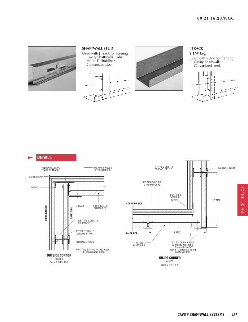
PAN HEAD SCREWS(TRACK TO TRACK)
CORNERBEAD
J TRACK
1" FIRE-SHIELD SHAFTLINER
1/2" FIRE-SHIELD C GYPSUM BOARD
1 5/8" TYPE S OR S-12 SCREWS 12" O.C.
1" TYPE S OR S-12 SCREWS 24" O.C.
SHAFTWALL STUD
CORR
IDOR
SID
E
SHAF
T SI
DE
OUTSIDE CORNER09260C
Scale: 2 1/4" = 1'-0"
Note: Type S screws for .020" studs, S-12 screws for .0329".
J TRACK
SHAFTWALL STUD1" TYPE S OR S-12SCREWS, 24" O.C.
1 5/8" TYPE S SCREWS, 12" O.C.
1/2" FIRE-SHIELD C GYPSUM BOARD
CORRIDOR SIDE
SHAFT SIDE
1" FIRE-SHIELD SHAFTLINER
2" x 2" x 20 GA. ANGLEeach angle fastened toJ Track with two 3/8"
Type S-12 screws at ceilingand two at floor.
INSIDE CORNER09260D
Scale: 2 1/4" = 1'-0"
12" MAX.
12" MAX.
DETAILS
SHAFTWALL STUDUsed with J Track for framing
Cavity Shaftwalls. Tabsretain 1" shaftliner.Galvanized steel.
J TRACK2 1/4" Leg.Used with I-Stud for framing
Cavity Shaftwalls.Galvanized steel.
128 CAVITY SHAFTWALL SYSTEMS
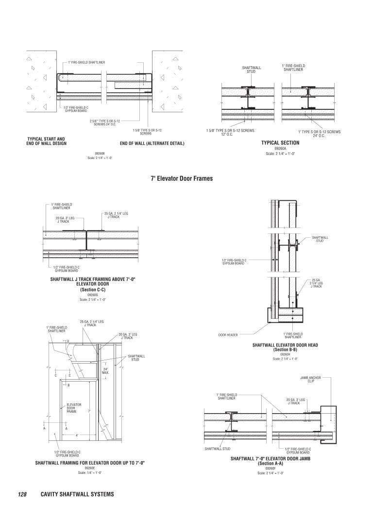
SHAFTWALL STUD
1/2" FIRE-SHIELD C GYPSUM BOARD
SHAFTWALL ELEVATOR DOOR HEAD(Section B-B)
09260HScale: 2 1/4" = 1'-0"
1" FIRE-SHIELD SHAFTLINER
25 GA.2 1/4" LEGJ TRACK
DOOR HEADER
1/2" FIRE-SHIELD C GYPSUM BOARD
SHAFTWALL J TRACK FRAMING ABOVE 7'-0"ELEVATOR DOOR
1" FIRE-SHIELD SHAFTLINER
20 GA. 3" LEG J TRACK
25 GA. 2 1/4" LEG J TRACK
09260GScale: 2 1/4" = 1'-0"
(Section C-C)
SHAFTWALL STUD 1/2" FIRE-SHIELD C GYPSUM BOARD
SHAFTWALL 7'-0" ELEVATOR DOOR JAMB(Section A-A)
09260FScale: 2 1/4" = 1'-0"
1" FIRE-SHIELD SHAFTLINER 20 GA. 3" LEG
J TRACK
JAMB ANCHOR CLIP
ELEVATORDOORFRAME
1/2" FIRE-SHIELD C GYPSUM BOARD
1" FIRE-SHIELD SHAFTLINER
25 GA. 2 1/4" LEG J TRACK
B
B
C C
A A
20 GA. 3" LEG J TRACK
SHAFTWALL STUD
24"MAX.
7'
4'
SHAFTWALL FRAMING FOR ELEVATOR DOOR UP TO 7'-0"09260E
Scale: 1/4" = 1'-0"
7' Elevator Door Frames
SHAFTWALL STUD
1" FIRE-SHIELD SHAFTLINER
1 5/8" TYPE S OR S-12 SCREWS 12" O.C.
1" TYPE S OR S-12 SCREWS 24" O.C.
TYPICAL SECTION09260A
Scale: 2 1/4" = 1'-0"
1" FIRE-SHIELD SHAFTLINER
1/2" FIRE-SHIELD C GYPSUM BOARD
2 5/8”" TYPE S OR S-12 SCREWS 24" O.C.
TYPICAL START AND END OF WALL DESIGN END OF WALL (ALTERNATE DETAIL)
1 5/8" TYPE S OR S-12 SCREWS
09260BScale: 2 1/4" = 1'-0"
129CAVITY SHAFTWALL SYSTEMS
09
21
16
.23
09 21 16.23/NGC
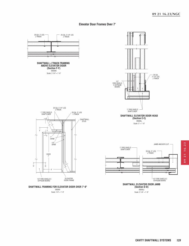
1/2" FIRE-SHIELD C GYPSUM BOARD
SHAFTWALL ELEVATOR DOOR JAMB(Section D-D)
09260JScale: 2 1/4" = 1'-0"
1" FIRE-SHIELD SHAFTLINER
20 GA. 3" LEG J TRACK
JAMB ANCHOR CLIP
SHAFTWALL ELEVATOR DOOR HEAD(Section E-E)
09260LScale: 3" = 1'-0"
1" FIRE-SHIELD SHAFTLINER
25 GA.2 1/4" LEGJ TRACK
1/2"FIRE-SHIELDC GYPSUM
BOARD
SHAFTWALL J TRACK FRAMING ABOVE ELEVATOR DOOR
(Section F-F)
20 GA. 3" LEG J TRACK
25 GA. 2 1/4" LEG J TRACK
09260KScale: 2 1/4" = 1'-0"
1/2" FIRE-SHIELD C GYPSUM BOARD
1" FIRE-SHIELD SHAFTLINER
25 GA. 2 1/4" LEG J TRACK
E
E
F F
D D
20 GA. 3" LEG J TRACK
SHAFTWALL STUD
4'
ELEVATORDOOR FRAME
OVER7'
1"SHIM
1/2"SHIM
SHAFTWALL FRAMING FOR ELEVATOR DOOR OVER 7'-0"09260I
Scale: 1/4" = 1'-0"
Elevator Door Frames Over 7'
130 CAVITY SHAFTWALL SYSTEMS
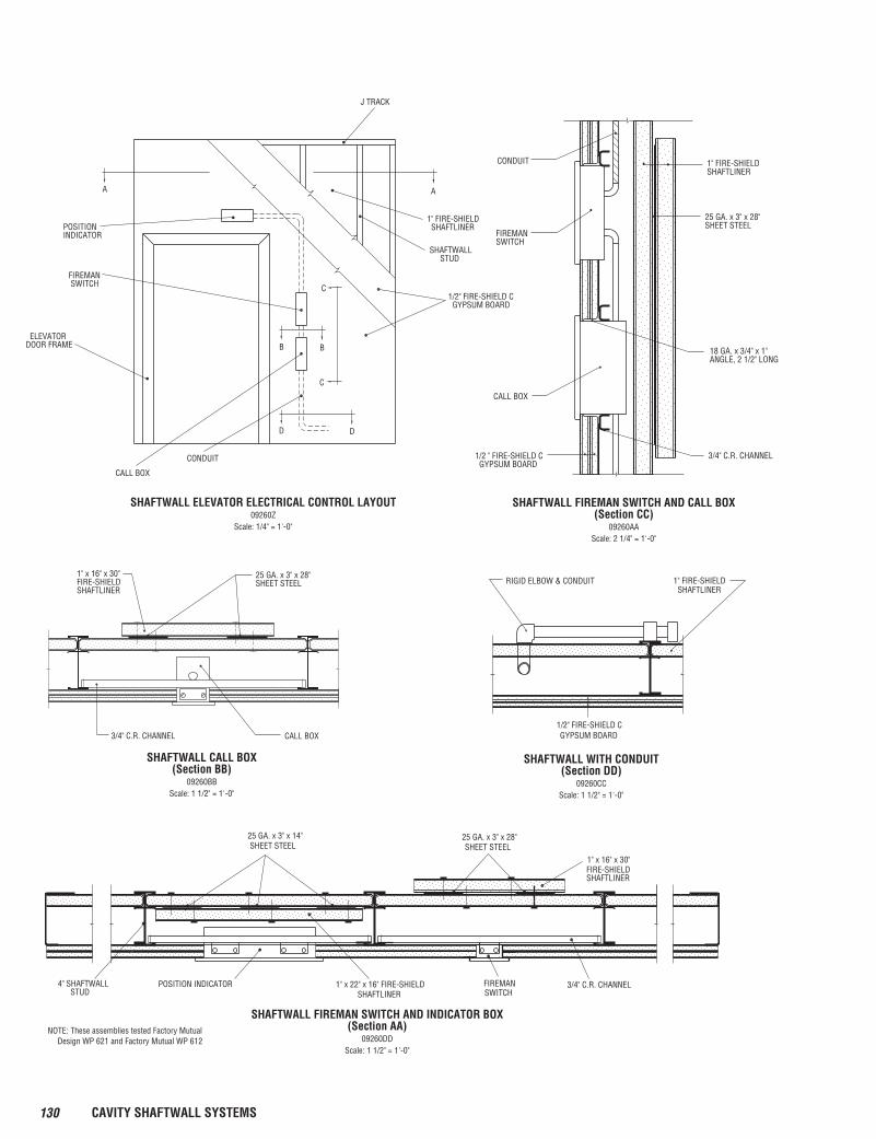
A
J TRACK
SHAFTWALL STUD
A
DD
BB
C
C1/2" FIRE-SHIELD C GYPSUM BOARD
1" FIRE-SHIELD SHAFTLINER
CONDUIT
CALL BOX
ELEVATORDOOR FRAME
FIREMAN SWITCH
POSITIONINDICATOR
SHAFTWALL ELEVATOR ELECTRICAL CONTROL LAYOUT09260Z
Scale: 1/4" = 1'-0"
CONDUIT
FIREMANSWITCH
CALL BOX
1/2 " FIRE-SHIELD C GYPSUM BOARD
1" FIRE-SHIELDSHAFTLINER
25 GA. x 3" x 28"SHEET STEEL
18 GA. x 3/4" x 1"ANGLE, 2 1/2" LONG
3/4" C.R. CHANNEL
SHAFTWALL FIREMAN SWITCH AND CALL BOX(Section CC)
09260AAScale: 2 1/4" = 1'-0"
25 GA. x 3" x 28"SHEET STEEL
1" x 16" x 30"FIRE-SHIELDSHAFTLINER
CALL BOX3/4" C.R. CHANNEL
SHAFTWALL CALL BOX(Section BB)
09260BBScale: 1 1/2" = 1'-0"
SHAFTWALL WITH CONDUIT(Section DD)
09260CCScale: 1 1/2" = 1'-0"
1/2" FIRE-SHIELD C GYPSUM BOARD
1" FIRE-SHIELDSHAFTLINER
RIGID ELBOW & CONDUIT
25 GA. x 3" x 28"SHEET STEEL
1" x 16" x 30"FIRE-SHIELD SHAFTLINER
3/4" C.R. CHANNEL
SHAFTWALL FIREMAN SWITCH AND INDICATOR BOX(Section AA)
09260DDScale: 1 1/2" = 1'-0"
FIREMANSWITCH
25 GA. x 3" x 14"SHEET STEEL
POSITION INDICATOR 1" x 22" x 16" FIRE-SHIELDSHAFTLINER
4" SHAFTWALL STUD
NOTE: These assemblies tested Factory Mutual Design WP 621 and Factory Mutual WP 612
131CAVITY SHAFTWALL SYSTEMS
09
21
16
.23
09 21 16.23/NGC
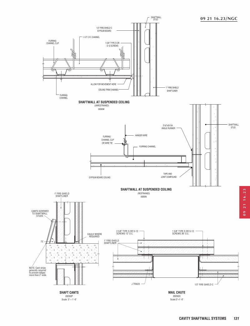
MAIL CHUTE09260O
Scale: 3" = 1'-0"
J TRACK
1" FIRE-SHIELDSHAFTLINER
2 5/8" TYPE S OR S-12SCREWS 12" O.C.
1 5/8" TYPE S OR S-12SCREWS 36" O.C.
1/2" FIRE-SHIELD C
SHAFT CANTS09260P
Scale: 3" = 1'-0"
NOTE: Cant stripsgenerally requiredto prevent ledgesmore than 2" wide.
CAULK WHERE REQUIRED
1" FIRE-SHIELD SHAFTLINER
CANTS SCREWED TO SHAFTWALL STUDS
75˚
SHAFTWALL AT SUSPENDED CEILING
FURRING CHANNEL
2"x2"x20 GA.ANGLE RUNNER
TAPE ANDJOINT COMPOUNDGYPSUM BOARD CEILING
HANGER WIRE FURRINGCHANNEL CLIP OR WIRE TIE
SHAFTWALL STUD
(RESTRAINED)09260N
1" FIRE-SHIELD SHAFTLINERCEILING TRIM CHANNEL
ALLOW FOR MOVEMENT HERE
SHAFTWALL AT SUSPENDED CEILING
1-1/2" C.R. CHANNEL
1-5/8" TYPE S OR S-12 SCREWS
FURRINGCHANNEL CLIP
SHAFTWALL
1/2" FIRE-SHIELD CGYPSUM BOARD
FURRING CHANNEL
(UNRESTRAINED)
09260M
STUD
132 CAVITY SHAFTWALL SYSTEMS
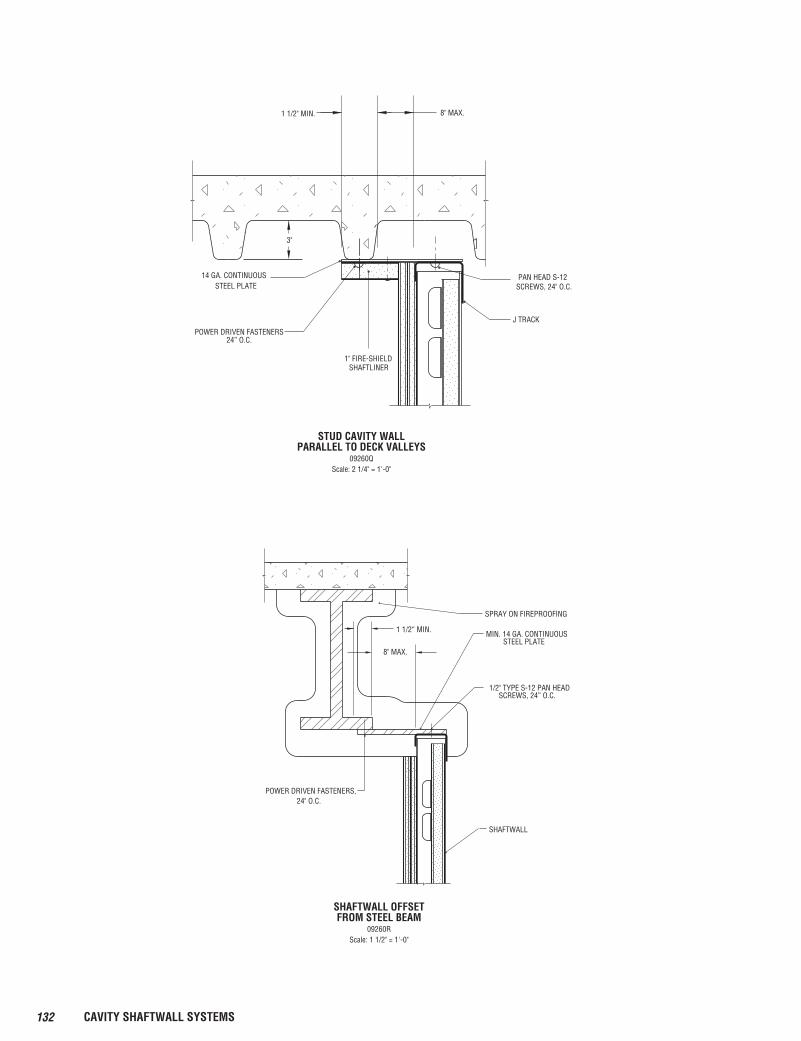
PAN HEAD S-12SCREWS, 24" O.C.
J TRACK
1" FIRE-SHIELDSHAFTLINER
14 GA. CONTINUOUSSTEEL PLATE
POWER DRIVEN FASTENERS24” O.C.
3"
1 1/2" MIN. 8" MAX.
STUD CAVITY WALLPARALLEL TO DECK VALLEYS
09260QScale: 2 1/4" = 1'-0"
8" MAX.
1 1/2“ MIN.
SHAFTWALL
MIN. 14 GA. CONTINUOUS STEEL PLATE
1/2" TYPE S-12 PAN HEAD SCREWS, 24” O.C.
POWER DRIVEN FASTENERS,24" O.C.
SPRAY ON FIREPROOFING
SHAFTWALL OFFSETFROM STEEL BEAM
09260RScale: 1 1/2" = 1'-0"
133CAVITY SHAFTWALL SYSTEMS
09
21
16
.23
09 21 16.23/NGC
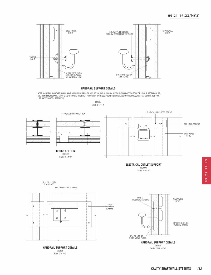
6" x 23 1/2" x 16 GA.S.M. PLATE, WELDOR SCREW ATTACH
TOGGLE BOLT
SHAFTWALL STUD
SHAFTWALL STUD
6" x 23 1/2" x 20 GA. S.M. PLATE
BOLT APPLIED BEFOREGYPSUM BOARD ON OTHER SIDE
NOTE: HANDRAIL BRACKET SHALL HAVE A MINIMUM AREA OF 3.25 SQ. IN. AND MINIMUM WIDTH ALONG BOTTOM EDGE OF 1 3/8" IF RECTANGULAR, AND A MINIMUM DIAMETER OF 2 3/8" IF ROUND IN ORDER TO COMPLY WITH 200 POUND PULLOUT AND/OR COMPRESSION TESTS (NFPA 101-1985 LIFE SAFETY CODE - BRACKETS).
HANDRAIL SUPPORT DETAILS
09260UScale: 3" = 1'-0"
OUTLET OR SWITCH BOX
CROSS SECTION09260V
Scale: 3" = 1'-0"
ELECTRICAL OUTLET SUPPORT09260W
Scale: 3" = 1'-0"
SHAFTWALL STUD
PAN HEAD SCREWS
2" x 24" x 16 GA. STEEL STRAP
6" x 26" x 20 GA. S.M. PLATE
NO. 10 MIN. S.M. SCREWS
TYPE SPAN HEADSCREWS
HANDRAIL SUPPORT DETAILS09260S
Scale: 2" = 1'-0"
SHAFTWALL STUD
1/2" FIRE-SHIELD C GYPSUM BOARD
TYPE SPAN HEAD SCREWS
HANDRAIL SUPPORT DETAILS09260T
Scale: 2 1/4" = 1'-0"
6" x 26" x 20 GASHEET METAL PLATE.
134 CAVITY SHAFTWALL SYSTEMS
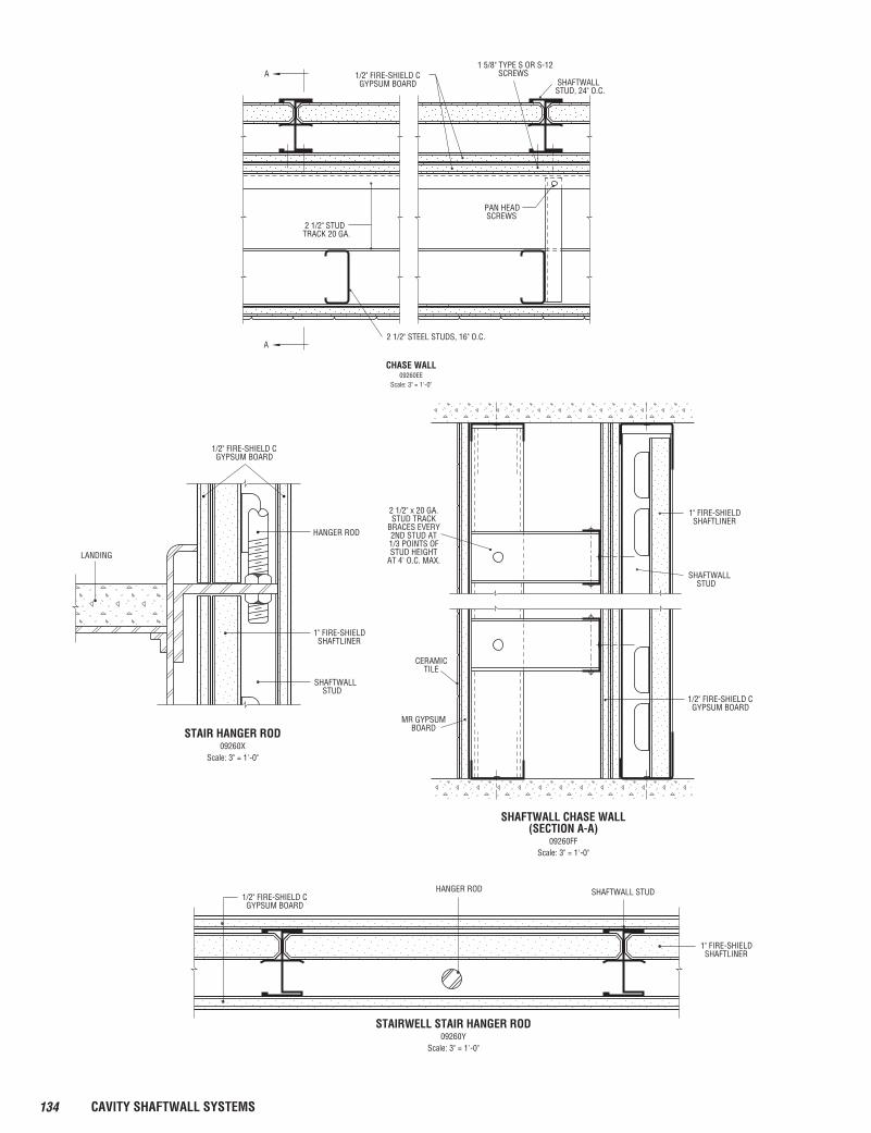
CHASE WALL09260EE
Scale: 3" = 1'-0"
2 1/2" STEEL STUDS, 16" O.C.
PAN HEAD SCREWS
SHAFTWALLSTUD, 24" O.C.
1 5/8" TYPE S OR S-12 SCREWSA
A
2 1/2" STUDTRACK 20 GA.
1/2" FIRE-SHIELD C GYPSUM BOARD
1" FIRE-SHIELD SHAFTLINER
SHAFTWALL STUD
2 1/2" x 20 GA.STUD TRACK
BRACES EVERY2ND STUD AT1/3 POINTS OFSTUD HEIGHT
AT 4' O.C. MAX.
CERAMICTILE
MR GYPSUMBOARD
SHAFTWALL CHASE WALL(SECTION A-A)
09260FFScale: 3" = 1'-0"
1/2" FIRE-SHIELD C GYPSUM BOARD
1/2" FIRE-SHIELD C GYPSUM BOARD
HANGER ROD
SHAFTWALL STUD
LANDING
STAIR HANGER ROD09260X
Scale: 3" = 1'-0"
1" FIRE-SHIELD SHAFTLINER
HANGER ROD SHAFTWALL STUD
1" FIRE-SHIELD SHAFTLINER
1/2" FIRE-SHIELD C GYPSUM BOARD
STAIRWELL STAIR HANGER ROD09260Y
Scale: 3" = 1'-0"
135CAVITY SHAFTWALL SYSTEMS
09
21
16
.23
09 21 16.23/NGC
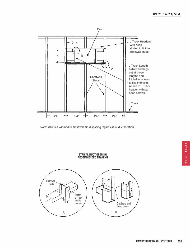
Note: Maintain 24" module Shaftwall Stud spacing regardless of duct location.
TYPICAL DUCT OPENINGRECOMMENDED FRAMING
ShaftwallStud
A.
Fasten J Track in this manner
B.
Cut here andbend down
J Track
J Track Lengthb+h+b and legscut at thoselengths andfolded as shownto slip into void.Attach to J Trackheader with panhead screws.
A
B
Duct
b
h
ShaftwallStuds
J Track Headerswith endsslotted to fit intoshaftwall studs.
24" 24" 24" 24"
136 CAVITY SHAFTWALL SYSTEMS
Shaftliner panels should behandled with care toprevent fracturing ordeformation of edges.
RECOMMENDATIONS
FRAMING AND SHAFTLINERCAVITY SHAFTWALL1. Locate and lay out partition
floor and ceiling lines toensure plumb partition.
2. Insure accurate studspacing to maintaingypsum board face layermodule.
3. Position top and bottom JTrack with long leg towardthe shaft along ceiling, floorand vertically at columnand/or wall where erectionof shaftwall will begin.Attach with power drivenfasteners 24" o.c. max.
4. Frame all openings cut into partitions for ducts, etc.with J Track as shown inaccompanying details toprotect cut gypsum coreedges and to provideresistance to bending andother stresses.
5. Cut shaftliner panels 1" lessthan ceiling height andinstall first by placingoutside vertical edgeagainst long leg of verticaltrack, plumb and attachwith Type S 1 5/8" Screws24" o.c.
6. Place studs within flangesof floor and ceiling trackand rotate into place. Slidestud tabs/flange snugly overedge of shaftlinerpreviously installed.
7. Install next shaftliner panelbetween tabs/flange ofstuds. Continue in thismanner until end ofpartition run. Occasionallycheck spacing of studs tomaintain 24" module.
8. At end of run, cut vertical J Track at least 2" short ofpartition height. Cutshaftliner 1/4" less thanremaining width ofpartition and 2" short of full height. Lay piece ofshaftliner 2" wide x lengthof opening in floor track assupport for last shaftlinerpanel. Fit cut edge ofshaftliner into vertical trackand, holding shaftliner andtrack together, slide paper
bound edge of shaftlinerinto stud. Align last paneland fasten the vertical trackwith appropriate fasteners24" o.c. max. Fastenshaftliner to vertical trackwith 1 5/8" Type S or S-12Screws 24" o.c. Seedrawing on page 126 foralternate detail.
9. Locate shaftwall horizontalend joints within the upperand lower third points ofwall. Stagger joints inadjacent panels to avoidcontinous horizontal joint.Shaftliner horizontal endjoints do not require taping,back blocking or framing.When using I-Studs theshaftliner panels shall be ofsufficient length to engagea minimum of two I-Studtabs along the edge.
GYPSUM BOARDApply first layer of 1/2" Fire-
Shield C (5/8" Fire-Shield)Gypsum Board horizontallyto face of studs with screwsspaced 24" o.c. Applysecond layer vertically withscrews spaced 12" o.c.(Use 1" Type S Screws onfirst layer, 1 5/8" Type SScrews on second layer for25 gauge nominal framing.)(Use 1" Type S-12 Screwson first layer, 1 5/8" Type S-12 Screws on secondlayer for 20 gauge orheavier framing.) Stagger allvertical and horizontaljoints. For proper jointtreatment, maintainuniform room temperaturebetween 50˚F and 70˚Fduring cold weather. Treatjoints of face layer withtape and joint compound.
CAULKINGCaulk Cavity Shaftwall system
with acoustical sealantwherever the wall isenclosing shafts wherepositive or negative airpressure exists. Caulkperimeter of wall and atany other place wherevoids create the possibilityof moving air causing dustaccumulation, noise orsmoke leakage. Caulkingshall be done incompliance with detailsspecified by thearchitect/designer.
AIR SHAFTSThe System is not designed to
serve as an unlined airsupply duct. Caulking isrecommended atperimeters and penetrationswherever the I-Stud Systemis used to enclose elevatorsor other shafts wherepositive or negativepressures will exist. Thecontractor installing thisSystem shall caulk incompliance with detailsspecified by the architect/designer. Proper caulkingwill seal perimeters andpenetrations to minimizeair noises and dustassociated with airmovement.
FRAMING FOR OPENINGSFrame doors and duct
openings with J Track. Use adequate structuralsupport for openings over48" wide. For openings upto 48" wide, use vertical JTrack on either side ofopenings. For head and sillof openings, place J Trackhorizontally acrossopenings. Cut J Track about12" longer than openings.Then cut flanges and foldback to nest over vertical J Track and fasten webs orflanges with two 3/8" TypeS or 1/2" Type S-12 PanHead Screws perconnection. When nesting J Track to J Track, cut offshort flange of horizontal J Track so it will fit oververtical J Track.
CALL BOXES ANDPOSITION INDICATORSProtect call boxes, position
indicators and fireman’sswitches as shown indrawings on page 130.
CHASESWhen possible, locate all
vertical rise, conduit, stairhangers, etc., within wallcavity. If the cavity in the 2 1/2" stud wall is not ofsufficient width, the 4" or 6" studs can be used forchases or erect chase wallsas shown on page 134.
ELEVATOR DOORSElevator door frames must be
braced and supportedindependently of the
shaftwall. However,shaftwall must be tied intoelevator door frames bybeing attached to jamb andanchor clips with pan headscrews. The 3" leg, nominal20 gauge J Track shall beused at the juncture of theelevator door frame and theCavity Shaftwall System. Seedrawings on pages 128 and129 for details.
Door frames (other thanelevator door frames) shouldbe formed from not lessthan 18 gauge steel, shopprimed, with throatopenings accurately formedto the nominal wallthickness plus 3/32". Framesmust have trim returns notless than 7/16" in width tobear flush against thegypsum board surface. Flooranchor plates should be 14gauge (min.) steel, firmlywelded to frames anddesigned with not less thantwo anchor holes 3" o.c.minimum to prevent framerotation. Anchor platesshould be securely fastenedto the floor with powerdriven fasteners havingminimum dimensions of3/16" diameter and 3/4"length. The type and size offastener is dependent on jobconditions, type of concreteor steel framing, etc., andmust be sufficient to providerigid, continuous anchorageto the frames. Jamb anchorclips should be formed from18 gauge (min.) steel, andwelded to jambs to provideadequate anchorage to jambframing as shown on details.Elevator door frames mustbe fastened to andsupported by the buildingstructure, separately framedand independent of thepartition. They shall besecurely anchored to thesills and to the buildingstructure or to the tracksupports. Anchors orfastenings to suit the wallconstruction are requiredand shall be not more than2' apart. See details onpages 128 and 129 forconnection of partition andelevator door frames.