Embed Size (px)
Citation preview
Appl. Phys. Lett. 106, 172601 (2015); https://doi.org/10.1063/1.4918775 106, 172601
© 2015 AIP Publishing LLC.
Cavity quantum electrodynamics usinga near-resonance two-level system:Emergence of the Glauber stateCite as: Appl. Phys. Lett. 106, 172601 (2015); https://doi.org/10.1063/1.4918775Submitted: 12 February 2015 . Accepted: 21 March 2015 . Published Online: 27 April 2015
B. Sarabi, A. N. Ramanayaka, A. L. Burin, F. C. Wellstood, and K. D. Osborn
ARTICLES YOU MAY BE INTERESTED IN
Surface participation and dielectric loss in superconducting qubitsApplied Physics Letters 107, 162601 (2015); https://doi.org/10.1063/1.4934486
A quantum engineer's guide to superconducting qubitsApplied Physics Reviews 6, 021318 (2019); https://doi.org/10.1063/1.5089550
Study of loss in superconducting coplanar waveguide resonatorsJournal of Applied Physics 109, 063915 (2011); https://doi.org/10.1063/1.3552890
Cavity quantum electrodynamics using a near-resonance two-level system:Emergence of the Glauber state
B. Sarabi,1,2 A. N. Ramanayaka,1,2 A. L. Burin,3 F. C. Wellstood,2,4 and K. D. Osborn1,4
1Laboratory for Physical Sciences, College Park, Maryland 20740, USA2Department of Physics, University of Maryland, College Park, Maryland 20742, USA3Department of Chemistry, Tulane University, New Orleans, Louisiana 70118, USA4Joint Quantum Institute, University of Maryland, College Park, Maryland 20742, USA
(Received 12 February 2015; accepted 21 March 2015; published online 27 April 2015)
Random tunneling two-level systems (TLSs) in dielectrics have been of interest recently because
they adversely affect the performance of superconducting qubits. The coupling of TLSs to qubits
has allowed individual TLS characterization, which has previously been limited to TLSs within
(thin) Josephson tunneling barriers made from aluminum oxide. Here, we report on the measure-
ment of an individual TLS within the capacitor of a lumped-element LC microwave resonator,
which forms a cavity quantum electrodynamics (CQED) system and allows for individual TLS
characterization in a different structure and material than demonstrated with qubits. Due to the
reduced volume of the dielectric (80 lm3), even with a moderate dielectric thickness (250 nm), we
achieve the strong coupling regime as evidenced by the vacuum Rabi splitting observed in the
cavity spectrum. A TLS with a coherence time of 3.2 ls was observed in a film of silicon nitride as
analyzed with a Jaynes-Cummings spectral model, which is larger than seen from superconducting
qubits. As the drive power is increased, we observe an unusual but explicable set of continuous and
discrete crossovers from the vacuum Rabi split transitions to the Glauber (coherent) state. VC 2015AIP Publishing LLC. [http://dx.doi.org/10.1063/1.4918775]
Cavity quantum electrodynamics (CQED) phenomena,
including vacuum Rabi splitting (VRS)1 and enhanced spon-
taneous emission,2 have greatly advanced the understanding
of photons coupled to atoms,3 ions,4,5 and superconducting
qubits.6–8 While the performance of the latter is often limited
by random tunneling two-level systems (TLSs),9–11 these
low-energy excitations have also served as local quantum
memories.12 In these studies, measurement of individual
TLSs properties, including their coherence times,13–15 have
previously been limited to thin (�1 nm) layers of aluminum
oxide, the prevalent material for Josephson junction tunnel-
ing barriers. However, other structures, including capacitors,
are used in qubits, and other materials are known to be scien-
tifically interesting due to unconventional TLS properties,
e.g., low TLS density.16–18 It is therefore desirable to charac-
terize individual TLSs in insulating structures and materials,
without being limited to tunneling-barrier structures.
Here, we report on a CQED study with TLSs where the
TLSs are coupled to a cavity, which allows us to characterize
an individual TLS in an insulating-thickness film of 250 nm.
In our experiment, the cavity is a circuit resonator made
from a capacitor containing amorphous silicon nitride dielec-
tric and an inductor. Similar to some amorphous silicon, the
type of silicon nitride has a lower density of TLSs when
compared to other amorphous solids.16,17 By using micro-
scopic volumes of this material, we reach the CQED strong-
coupling regime using a single strongly coupled TLS, and
observe VRS below a single photon (on average) in the
cavity. We also observe a quantum-to-Glauber (coherent)
crossover as the drive power is increased, which results in a
wishbone-shaped transmission. This results from two differ-
ent phenomena emerging from the VRS transitions as the
coherent drive power is increased. The weakly coupled TLSs
are also studied, and can be clearly distinguished from the
strongly coupled TLS.
Microwave resonators (each containing an inductor and
a capacitor) were made with superconductor-insulator-super-
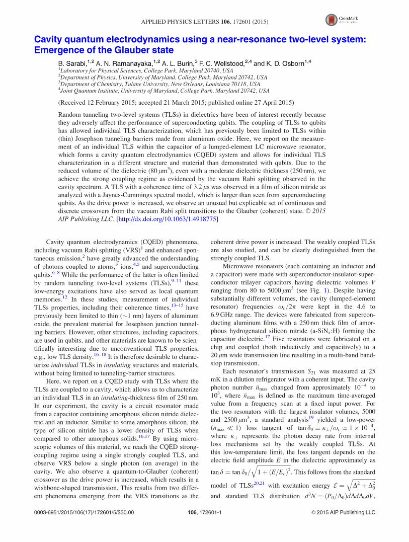
conductor trilayer capacitors having dielectric volumes Vranging from 80 to 5000 lm3 (see Fig. 1). Despite having
substantially different volumes, the cavity (lumped-element
resonator) frequencies xc=2p were kept in the 4.6 to
6.9 GHz range. The devices were fabricated from supercon-
ducting aluminum films with a 250 nm thick film of amor-
phous hydrogenated silicon nitride (a-SiNx:H) forming the
capacitor dielectric.17 Five resonators were fabricated on a
chip and coupled (both inductively and capacitively) to a
20 lm wide transmission line resulting in a multi-band band-
stop transmission.
Each resonator’s transmission S21 was measured at 25
mK in a dilution refrigerator with a coherent input. The cavity
photon number �nmax changed from approximately 10�4 to
103, where �nmax is defined as the maximum time-averaged
value from a frequency scan at a fixed input power. For
the two resonators with the largest insulator volumes, 5000
and 2500 lm3, a standard analysis19 yielded a low-power
(�nmax � 1) loss tangent of tan d0 � j?=xc ’ 1� 10�4,
where j? represents the photon decay rate from internal
loss mechanisms set by the weakly coupled TLSs. At
this low-temperature limit, the loss tangent depends on the
electric field amplitude E in the dielectric approximately as
tan d ¼ tan d0=
ffiffiffiffiffiffiffiffiffiffiffiffiffiffiffiffiffiffiffiffiffiffiffiffi1þ ðE=EcÞ2
q. This follows from the standard
model of TLSs20,21 with excitation energy E ¼ffiffiffiffiffiffiffiffiffiffiffiffiffiffiffiffiffiD2 þ D2
0
q
and standard TLS distribution d3N ¼ ðP0=D0ÞdDdD0dV,
0003-6951/2015/106(17)/172601/5/$30.00 VC 2015 AIP Publishing LLC106, 172601-1
APPLIED PHYSICS LETTERS 106, 172601 (2015)
where N is the TLS number, P0 ¼ 3�0�r tan d0=pp2; D0 repre-
sents the tunneling energy and �0�r is the dielectric permittiv-
ity. D denotes the offset energy between the two wells, which
is perturbed by the interaction energy p � E ¼ pE cos h of the
TLS dipole moment p, at an angle h with respect to the elec-
tric field E. We measured Ec¼ 4.6 V/m for the two largest-
volume resonators. The same value was found and expected
for both resonators since for large (bulk) samples, Ec is only
dependent on a characteristic TLS coherence time and Rabi
frequency. At the critical field in these resonators, the photon
number is greater than 1, which is a consequence of small
coupling between the TLSs and cavity relative to the TLSs’
decay rate, and allows a classical treatment of the field.22
However, for the smaller volume (larger CQED coupling)
regime discussed below, this no longer holds.
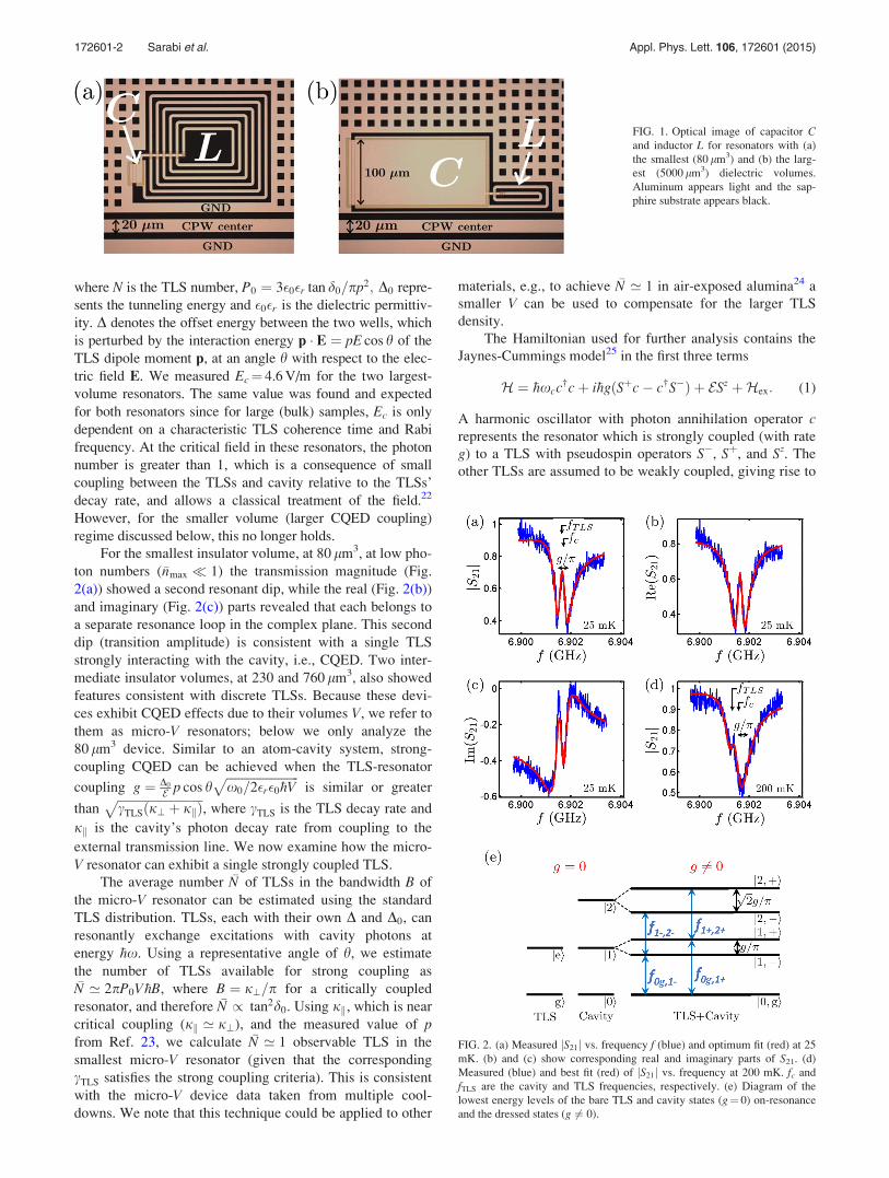
For the smallest insulator volume, at 80 lm3, at low pho-
ton numbers (�nmax � 1) the transmission magnitude (Fig.
2(a)) showed a second resonant dip, while the real (Fig. 2(b))
and imaginary (Fig. 2(c)) parts revealed that each belongs to
a separate resonance loop in the complex plane. This second
dip (transition amplitude) is consistent with a single TLS
strongly interacting with the cavity, i.e., CQED. Two inter-
mediate insulator volumes, at 230 and 760 lm3, also showed
features consistent with discrete TLSs. Because these devi-
ces exhibit CQED effects due to their volumes V, we refer to
them as micro-V resonators; below we only analyze the
80 lm3 device. Similar to an atom-cavity system, strong-
coupling CQED can be achieved when the TLS-resonator
coupling g ¼ D0
E p cos hffiffiffiffiffiffiffiffiffiffiffiffiffiffiffiffiffiffiffiffiffiffiffiffix0=2�r�0�hV
pis similar or greater
thanffiffiffiffiffiffiffiffiffiffiffiffiffiffiffiffiffiffiffiffiffiffiffiffiffiffiffifficTLSðj? þ jkÞ
p, where cTLS is the TLS decay rate and
jk is the cavity’s photon decay rate from coupling to the
external transmission line. We now examine how the micro-
V resonator can exhibit a single strongly coupled TLS.
The average number �N of TLSs in the bandwidth B of
the micro-V resonator can be estimated using the standard
TLS distribution. TLSs, each with their own D and D0, can
resonantly exchange excitations with cavity photons at
energy �hx. Using a representative angle of h, we estimate
the number of TLSs available for strong coupling as�N ’ 2pP0V�hB, where B ¼ j?=p for a critically coupled
resonator, and therefore �N / tan2d0. Using jk, which is near
critical coupling (jk ’ j?), and the measured value of pfrom Ref. 23, we calculate �N ’ 1 observable TLS in the
smallest micro-V resonator (given that the corresponding
cTLS satisfies the strong coupling criteria). This is consistent
with the micro-V device data taken from multiple cool-
downs. We note that this technique could be applied to other
materials, e.g., to achieve �N ’ 1 in air-exposed alumina24 a
smaller V can be used to compensate for the larger TLS
density.
The Hamiltonian used for further analysis contains the
Jaynes-Cummings model25 in the first three terms
H ¼ �hxcc†cþ i�hgðSþc� c†S�Þ þ ESz þHex: (1)
A harmonic oscillator with photon annihilation operator crepresents the resonator which is strongly coupled (with rate
g) to a TLS with pseudospin operators S�, Sþ, and Sz. The
other TLSs are assumed to be weakly coupled, giving rise to
FIG. 1. Optical image of capacitor Cand inductor L for resonators with (a)
the smallest (80 lm3) and (b) the larg-
est (5000 lm3) dielectric volumes.
Aluminum appears light and the sap-
phire substrate appears black.
FIG. 2. (a) Measured jS21j vs. frequency f (blue) and optimum fit (red) at 25
mK. (b) and (c) show corresponding real and imaginary parts of S21. (d)
Measured (blue) and best fit (red) of jS21j vs. frequency at 200 mK. fc and
fTLS are the cavity and TLS frequencies, respectively. (e) Diagram of the
lowest energy levels of the bare TLS and cavity states (g¼ 0) on-resonance
and the dressed states (g 6¼ 0).
172601-2 Sarabi et al. Appl. Phys. Lett. 106, 172601 (2015)
j?. The external coupling Hamiltonian Hex ¼ �hxdd†d þ�hXðd†cþ c†dÞ accounts for the coupling to the transmission
line with photon annihilation operator d.
At small average photon numbers in the cavity, �nmax � 1,
and in the low-temperature limit (kBT � �hx), the dominant
TLS can be treated as an oscillator. At higher temperatures
(kBT � �hx), we used a mean field approach and replace Sz
with its thermodynamic average hSzi ¼ � 12
tanhð�hx=2kBTÞ.The single-photon transmission, appropriate for �nmax � 1 is
S21 ’ 1�~jk=2
~jk2þ j?
2þ i x� xcð Þ þ
g2tanh �hx=2kBTð ÞcTLS
2þ i x� xTLSð Þ
: (2)
The complex coupling rate ~jk has a small imaginary compo-
nent Imð~jkÞ � Reð~jkÞð’jkÞ and similar to many classical
resonators, it plays a negligible role in our device, cf. Ref.
19.
Under strong coupling conditions, Eq. (2) shows a VRS:
two distinct transition amplitudes. From Eq. (1), the two vac-
uum transition frequencies become 2pf0g;16 ¼ xc þ d=2
6
ffiffiffiffiffiffiffiffiffiffiffiffiffiffiffiffiffiffiffiffiffiffiffig2 þ ðd=2Þ2
q, where d ¼ xTLS � xc (see Fig. 2(e)). From
Eq. (2), it follows that a single TLS at resonance with the
cavity can be distinguished if its maximum response exceeds
the average response of the weakly coupled TLSs, i.e.,
v ¼ pP0�hV=6T1 < 1, where T1 ¼ 1=cTLS is the TLS relaxa-
tion time.
Figures 2(a)–2(c) show a least squares Monte Carlo
(LSM) fit to the data using the low-temperature limit of Eq.
(2).26 The fit yields fc ¼ xc=2p ¼ 6:901689 GHz and j? ¼1:92 MHz for the resonator and fTLS ¼ xTLS=2p ¼ 6:901629
GHz and T2 ¼ 2=cTLS ¼ 3:2 ls for the TLS, where the T2 is
the coherence time of the resonant TLS. This TLS coherence
time is at least 3 times larger than previously characterized
individual TLSs.14,15
The fit also yields jk=2p ¼ 493 kHz and g=p ¼ 366
kHz, where from g we obtain a transition dipole moment
of pmin ¼ ðD0=EÞp cos h ¼ 1:6 Debye ¼ 0:34 eA ððD0=EÞcos h � 1Þ. This minimum extracted dipole size for the TLS
is consistent with a previous measurement of the same mate-
rial.23 The spontaneous photon emission rate given by the
Purcell effect (with jk and pmin) is calculated to be within a
factor of 2 of the measured cTLS, indicating that T2 may be
limited by the photon, rather than phonon, emission.
Figure 2(d) shows data from the same micro-V device at
T¼ 200 mK. We also fit Eq. (2) to this data with jk fixed to
the low temperature result. The fit reveals g=p ¼ 360 kHz,
showing almost no effect from temperature, while
fTLS ¼ 6:901318 GHz and fc¼ 6.901576 GHz show a small
shift caused by the weakly coupled TLS bath, as expected.
Unlike the low-temperature result, d is now approximately
equal to 2g and causes an unequal superposition of the bare
states. The high (low) frequency side of the VRS, j0; gi !j1;þi (j0; gi ! j1;�i), involves a cavity-like (TLS-like)
state, and hence, the cavity-measured amplitude at f0g;1þ(f0g;1�) is larger (smaller) than an equal-superposition state.
Equation (2) with the remaining fit values, T1ð200 mKÞ¼ 0:57 ls and j?, allow us to calculate the ratio of the
TLS-like transition amplitude on the background of the
cavity-like transition amplitude as 4g2tanhð�hx=2kBTÞ T1=j?¼ 0.67, where tanhð�hx=2kBTÞ ¼ 0:68. The T1ð200 mKÞ is
shorter than expected from phonon emission, which scales as
tanhð�hx=2kBTÞ and predicts T1ð200 mKÞ ¼ 1:1 ls. This dis-
crepancy is qualitatively consistent with additional dephasing
expected from spectral diffusion27 and the temperature de-
pendence of tunneling barrier TLSs,15 observed here as a
larger linewidth (�1=T1).
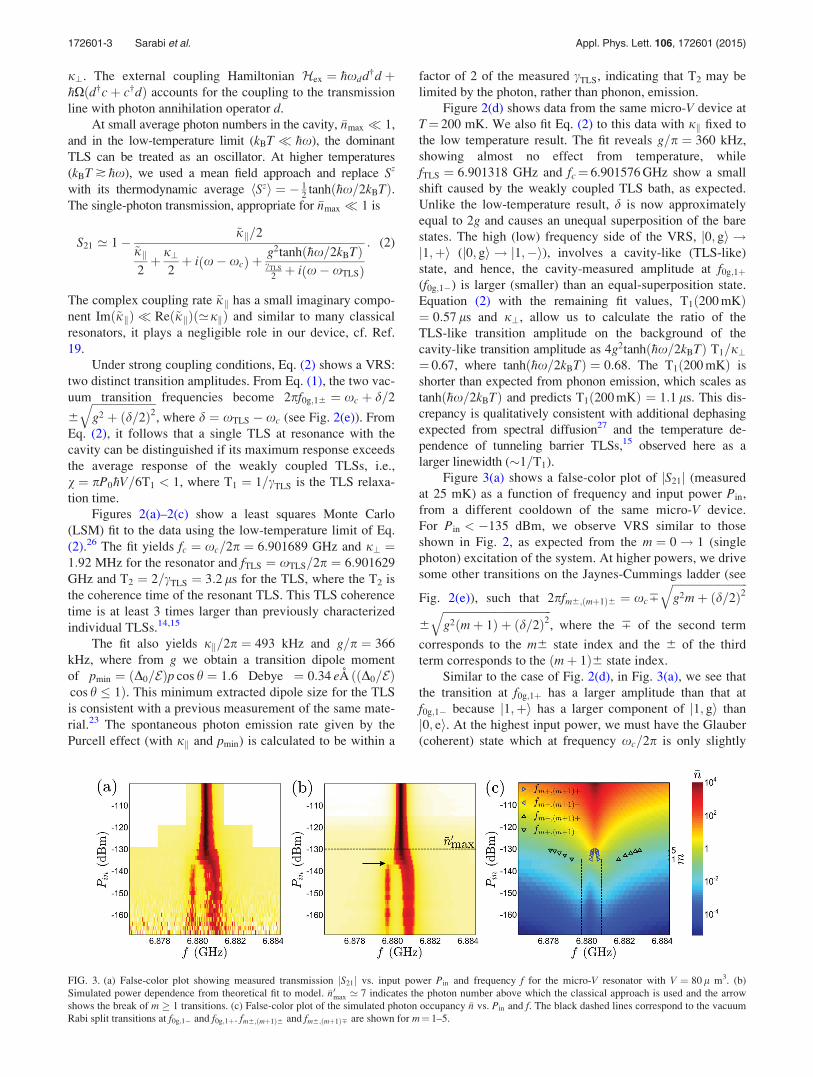
Figure 3(a) shows a false-color plot of jS21j (measured
at 25 mK) as a function of frequency and input power Pin,
from a different cooldown of the same micro-V device.
For Pin < �135 dBm, we observe VRS similar to those
shown in Fig. 2, as expected from the m ¼ 0! 1 (single
photon) excitation of the system. At higher powers, we drive
some other transitions on the Jaynes-Cummings ladder (see
Fig. 2(e)), such that 2pfm6;ðmþ1Þ6 ¼ xc7
ffiffiffiffiffiffiffiffiffiffiffiffiffiffiffiffiffiffiffiffiffiffiffiffiffiffiffig2mþ ðd=2Þ2
q
6
ffiffiffiffiffiffiffiffiffiffiffiffiffiffiffiffiffiffiffiffiffiffiffiffiffiffiffiffiffiffiffiffiffiffiffiffiffiffiffig2ðmþ 1Þ þ ðd=2Þ2
q, where the 7 of the second term
corresponds to the m6 state index and the 6 of the third
term corresponds to the ðmþ 1Þ6 state index.
Similar to the case of Fig. 2(d), in Fig. 3(a), we see that
the transition at f0g;1þ has a larger amplitude than that at
f0g;1� because j1;þi has a larger component of j1; gi than
j0; ei. At the highest input power, we must have the Glauber
(coherent) state which at frequency xc=2p is only slightly
FIG. 3. (a) False-color plot showing measured transmission jS21j vs. input power Pin and frequency f for the micro-V resonator with V ¼ 80 l m3. (b)
Simulated power dependence from theoretical fit to model. �n 0max ’ 7 indicates the photon number above which the classical approach is used and the arrow
shows the break of m 1 transitions. (c) False-color plot of the simulated photon occupancy �n vs. Pin and f. The black dashed lines correspond to the vacuum
Rabi split transitions at f0g;1� and f0g;1þ. fm6;ðmþ1Þ6 and fm6;ðmþ1Þ7 are shown for m¼ 1–5.
172601-3 Sarabi et al. Appl. Phys. Lett. 106, 172601 (2015)
smaller than f0g;1þ. We also notice that as the power is
increased there is a continuous crossover from j0; gi !j1;þi to higher-energy transitions eventually reaching the
Glauber (coherent) state. These transitions are excited from
j1;þi and include the transitions jm;þi ! jmþ 1;þi in
climbing the Jaynes-Cummings ladder (see j1;þi ! j2;þiin Fig. 2(e)).
In contrast, as we start from f0g;1�, we observe a differ-
ent behavior which is caused by the detuning
(jfc � f0g;1�j > jfc � f0g;1þj). A gap of transition amplitude
appears between the j0; gi ! j1;�i transition and the higher
power transitions jm;�i ! jmþ 1;�i (the jm;6i !jmþ 1;6i transitions are included in the (high-power)
Glauber state according to the Jaynes-Cummings model). A
break between the j0; gi ! j1;�i and the higher jm;�i !jmþ 1;�i transitions has been previously observed as a
quantum-to-classical crossover in a superconducting qubit-
resonator system, but there the crossover to the coherent
state, which includes the jm;þi ! jmþ 1;þi transitions,
was not observed due to the use of an incoherent drive
source.28 The break from the j0; gi ! j1;�i transition to
other transitions has allowed for demonstrations of photon
blockade.29
We analyzed the nonlinear data in high and low input
power regimes separately. In both regimes, the frequency
scan data was fit at each measurement input power. The low-
power regime starts below P0in ¼ �130 dBm, where
�nmax ¼ �n0max ’ 7. For the high power coherent-like state,
fmþ;ðmþ1Þþ is very close to fm�;ðmþ1Þ� and the width of the
cavity resonance is primarily determined by j? (the weakly
coupled TLS bath) which allows a classical field analysis.19
A LSM fit to this regime gave xc=2p ¼ 6:880434 GHz,
jk=2p ¼ 491 kHz, and j?ðPinÞ, where the weakly coupled
TLS are influenced by Pin, similar to previous classical satu-
ration field studies. In the low-power regime, we used a cal-
culation of the density matrix, Eq. (1), using the Lindblad
formalism. A LSM fit to this data, using jk and xc from
above, gave g=p ¼ 1:00 MHz, xTLS=2p ¼ 6:880106 GHz,
and T1 ¼ 1=cTLS ¼ 325 ns and the remaining regime for
j?ðPinÞ, which is approximately equal to j? of the largest-
volume device when Pin � P0in.
A combination of the fits and the resulting �n are shown
in Figs. 3(b) and 3(c), respectively. Notice that �n � 1 only
near fc and at Pin > �136 dBm, while at lower powers, �n has
a local maximum in frequency scans at f0g;1� and f0g;1þ. The
transition frequencies fmþ;ðmþ1Þþ and fm�;ðmþ1Þ� are plotted in
Fig. 3(c), where the vertical placement of m is only sugges-
tive. This shows how the occupancy of the Jaynes-
Cummings transitions near fc are populated from j1;þirather than j1;�i where spontaneous emission can cause the
j2;þi ! j1;�i transition. In this system, the TLS spontane-
ous emission is small cTLS=4ðj? þ jkÞ ’ 0:1� 1, and is
believed to switch the field phase during jm;þi $ jm61;�itransitions.30 The other transitions, jm;�i ! jmþ 1;þi and
jm;þi ! jmþ 1;�i, are suppressed due to low occupancy
of j1;6i (�n � 1) at the frequency of these transitions, as
suggested by the figure.
In conclusion, we have measured and characterized indi-
vidual TLSs in an insulating film using strong TLS-resonator
coupling. The dielectric in our experiment is approximately
2 orders of magnitude thicker than a tunneling barrier used
in previous (qubit) studies of individual TLS.
We observe the VRS transitions at single-photon
powers, and a crossover to the Glauber (coherent) state as
the input measurement power is increased. The continuous
crossover from one VRS transition and a discontinuous
crossover from the other is explained by a Jaynes Cummings
model. This differs from superconducting qubit CQED stud-
ies which have an incoherent drive tone to study this cross-
over, where more than two levels of their qubit are used for
quantitative comparison to simulations.
The device design allows other dielectrics to be studied
in the future, in contrast to studies of TLS in the Josephson
tunneling barriers of qubits which (typically) use aluminum
oxide. One TLS in our SiNx film was found to have a coher-
ence time of T2 ¼ 3:2 ls, which is longer than those of
superconducting qubits. The difference may be due to the
capacitor structure, which allows the TLS to be isolated from
the electrodes, or the material. This T2 time is similar to that
of the original measurement of the popular transmon qubit
and we believe that in the CQED architecture, TLS with
longer coherence times will be found. One TLS was found to
have strong coupling at g=p ¼ 1 MHz, such that the VRS
transitions are well resolved, and in the future one transition
(from the CQED system) could be operated as a qubit with-
out the use of a Josephson-junction qubit.
The authors thank C. Lobb, R. Simmonds, B. Palmer, Y.
Rosen, M. Stoutimore, M. Khalil, and S. Gladchenko for
many useful discussions. A. Burin acknowledges support
through Army Research Office Grant vv911NF-13-1-0186,
the LA Sigma Program, and the NSF EPCORE LINK
Program.
1J. J. Sanchez-Mondragon, N. B. Narozhny, and J. H. Eberly, Phys. Rev.
Lett. 51, 1925 (1983).2P. Goy, J. M. Raimond, M. Gross, and S. Haroche, Phys. Rev. Lett. 50,
1903 (1983).3Y. Kaluzny, P. Goy, M. Gross, J. M. Raimond, and S. Haroche, Phys. Rev.
Lett. 51, 1175 (1983).4J. I. Cirac and P. Zoller, Phys. Rev. Lett. 74, 4091 (1995).5D. Leibfried, R. Blatt, C. Monroe, and D. Wineland, Rev. Mod. Phys. 75,
281 (2003).6A. Wallraff, D. I. Schuster, A. Blais, L. Frunzio, R.-S. Huang, J. Majer, S.
Kumar, S. M. Girvin, and R. J. Schoelkopf, Nature 431, 162 (2004).7A. Blais, R.-S. Huang, A. Wallraff, S. M. Girvin, and R. J. Schoelkopf,
Phys. Rev. A 69, 062320 (2004).8M. D. Reed, L. DiCarlo, B. R. Johnson, L. Sun, D. I. Schuster, L. Frunzio,
and R. J. Schoelkopf, Phys. Rev. Lett. 105, 173601 (2010).9J. M. Martinis, K. B. Cooper, R. McDermott, M. Steffen, M. Ansmann, K.
D. Osborn, K. Cicak, S. Oh, D. P. Pappas, R. W. Simmonds, and C. C. Yu,
Phys. Rev. Lett. 95, 210503 (2005).10R. W. Simmonds, K. M. Lang, D. A. Hite, S. Nam, D. P. Pappas, and J. M.
Martinis, Phys. Rev. Lett. 93, 077003 (2004).11K. B. Cooper, M. Steffen, R. McDermott, R. W. Simmonds, S. Oh, D. A.
Hite, D. P. Pappas, and J. M. Martinis, Phys. Rev. Lett. 93, 180401 (2004).12M. Neeley, M. Ansmann, R. C. Bialczak, M. Hofheinz, N. Katz, E.
Lucero, A. O’Connell, H. Wang, A. Cleland, and J. M. Martinis, Nat.
Phys. 4, 523 (2008).13Z. Kim, V. Zaretskey, Y. Yoon, J. F. Schneiderman, M. D. Shaw, P. M.
Echternach, F. C. Wellstood, and B. S. Palmer, Phys. Rev. B 78, 144506
(2008).14Y. Shalibo, Y. Rofe, D. Shwa, F. Zeides, M. Neeley, J. M. Martinis, and
N. Katz, Phys. Rev. Lett. 105, 177001 (2010).15J. Lisenfeld, C. M€uller, J. H. Cole, P. Bushev, A. Lukashenko, A.
Shnirman, and A. V. Ustinov, Phys. Rev. Lett. 105, 230504 (2010).
172601-4 Sarabi et al. Appl. Phys. Lett. 106, 172601 (2015)

16D. R. Queen, X. Liu, J. Karel, T. H. Metcalf, and F. Hellman, Phys. Rev.
Lett. 110, 135901 (2013).17H. Paik and K. D. Osborn, Appl. Phys. Lett. 96, 072505 (2010).18A. D. O’Connell, M. Ansmann, R. C. Bialczak, M. Hofheinz, N. Katz, E.
Lucero, C. McKenney, M. Neeley, H. Wang, E. M. Weig, A. N. Cleland,
and J. M. Martinis, Appl. Phys. Lett. 92, 112903 (2008).19M. S. Khalil, M. J. A. Stoutimore, F. C. Wellstood, and K. D. Osborn,
J. Appl. Phys. 111, 054510 (2012).20P. W. Anderson, B. I. Halperin, and C. M. Varma, Philos. Mag. 25, 1 (1972).21W. Phillips, J. Low. Temp. Phys. 7, 351 (1972).22M. V. Schickfus and S. Hunklinger, Phys. Lett. A 64, 144 (1977).23M. S. Khalil, S. Gladchenko, M. J. A. Stoutimore, F. C. Wellstood, A. L.
Burin, and K. D. Osborn, Phys. Rev. B 90, 100201 (2014).24M. S. Khalil, M. J. A. Stoutimore, S. Gladchenko, A. M. Holder, C. B.
Musgrave, A. C. Kozen, G. Rubloff, Y. Q. Liu, R. G. Gordon, J. H. Yum,
S. K. Banerjee, C. J. Lobb, and K. D. Osborn, Appl. Phys. Lett. 103,
162601 (2013).25E. Jaynes and F. W. Cummings, Proc. IEEE 51, 89 (1963).26B. Sarabi, “Cavity quantum electrodynamics of nanoscale two-level
systems,” Ph.D. dissertation (University of Maryland, College Park,
2014).27J. L. Black and B. I. Halperin, Phys. Rev. B 16, 2879 (1977).28J. M. Fink, L. Steffen, P. Studer, L. S. Bishop, M. Baur, R. Bianchetti, D.
Bozyigit, C. Lang, S. Filipp, P. J. Leek, and A. Wallraff, Phys. Rev. Lett.
105, 163601 (2010).29C. Lang, D. Bozyigit, C. Eichler, L. Steffen, J. M. Fink, A. A. Abdumalikov,
M. Baur, S. Filipp, M. P. da Silva, A. Blais, and A. Wallraff, Phys. Rev. Lett.
106, 243601 (2011).30P. Alsing and H. J. Carmichael, Quantum Opt.: J. Eur. Opt. Soc. Part B 3,
13 (1991).
172601-5 Sarabi et al. Appl. Phys. Lett. 106, 172601 (2015)