Embed Size (px)
Citation preview

SEMICONDUCTOR OPTOELECTRONICS
Cavity modelling in stacked quantum well slabs for optically pumped lasers
H.A. Tan . 2.-J. Xin and H.N. Rutt
Abstract: The paper discusses a model to estimate the diffraction loss in stacked quantum well slabs for optically pumped lasers. Two quantum well slabs, cleaved from the same strip, are stacked together with the front sides facing each other to form the laser cavity. Misalignment and diffcrent slab sizes are possible, which may result in additional diffraction loss. The model is based on the diffraction integral theory to calculate the fundamental mode in a plane mirror resonator. Model results suggest that, for a small misalignment size of a few percent of the Wavelength, the diffraction loss is relatively small compared with other sources of loss in the laser system. Hencc, the stacked scheme is feasible for the long wavelength far-infrared region but not suitable for shorter wavelengths in thc mid- or near-infrared regions. This model is in general applicable to other optically pumped quantum well lasers.
1 Introduction
Rcscarch into realising a semiconductor terahertz (THz) laser has seen increasing activity in the past decade [I-61. This is driven mainly by the lack of a compact, convenient coherent source in THz frequencies (-1-10 THr), despite the potential applications, e.g. communication, security screening and medical imaging. The increasing interest follows the improved devclopment of growing complex epitaxial layers and successful demonstration of laser emissions utilising the intersubband transitions [7-91. However, there has yet to be a laser transition below thc longitudinal optical (LO) phonon energy in the host material (-36 meV i n CaAs and -34 mcV in InGaAs); only electroluminescence [ 10-12] has been reported so far. Both electrically and optically pumped devices have been proposed - in particular, the attempt to increase the laser wavelength of quantum cascade lasers (QCL) to the THa rcgion [13, 141. Another approach is optically pumped quantum well (QW) lasers [6, IS], using for example a COz gas laser as a pump source. The optically pumped QW lasers, without the need for injector layers and contact layer, have the advantage of simpler design and processing as compared to the electrically pumped QCL counterparts. Although requiring an external pumping source, optically pumped lasers have relatively lower pump power threshold and internal losses due to free carrier absorption.
Q IEE, 2003 IEE Pmceedin@ online no. 20030427 DUI: 1O.IO49/ip-opl:20030427 Papcr first received 28th May 2002 and in revised form 17th Fehrualy 2003 H.A. Tan and I.I.N. Rutt are with the Optoelectronics Research Centre, University of Southampton, Southampton SO17 1B.I. UK Z.-J. Xin war with the Optoelectronics Research Centre. University of Southarriplon and IS iiuw with the Depadment of Physics and Astronomy. University of Southampton, Southampton SO11 IBJ, UK
I E t P,or..-upiucl~~,~"ri, Ibl. /XI, MI 2. .Aprd/ 2003
One of the well known difficulties in achieving laser action in this region, also known as far infrared (FIR), is the issue of confining and guiding the THz laser emission in the active layers [ I I]. There is poor overlap between the laser mode ( 2 = 30 to 300 pm) with the active layers (a few micromctres). For optically pumped THz lasers, the pump wavelength is typically 10.6pm since the CO2 laser is normally the pump source, although it may he replaced by a mid-infrarcd QCL. This inefficiency due to thc large difference between the modes and the active layer presents a technical challenge to find a way to guide the long wavelength emission, utilising thc current epitaxial grow- ing techniques. The use of multiple quantum wells (MQW), typically more than SO periods, improves the confinement factor of the laser mode by increasing the total thickness of the active layer. However, the number of epi-laycrs that can be grown on a substrate is limited by the uniformity and morphology fluctuation from the grow- ing process, as well as inhomogeneous broadening issues [16, 171. Typically, the epitaxial thickness grown by molecular beam epitaxy (MBE) is of the order of 10 pm. On the other hand the free carrier absorption loss, which is very serious in this region since the loss is approxi- mately proportional to the square of the wavelength 2, has to he minimised. These issues have fundamentally hindered the success of any lasing from various attempts to design a compact, solid state THz source to date. Recently, surface plasmon guided QCLs [14, 181 have been demonstrated at wavelength up to 24 pm and may be attractive in the THz region.
In this paper, we propose a novel pumping scheme of stacking two identical QW slabs, with the top grown surfaces facing each other, as depicted in Fig. 1. The advantages and disadvantages of the design will be discussed. A model is introduced to estimate the diffraction loss associated with any misalignment or difference in slab width that may result from this scheme. Although the discussion here is based on the optically pumped THz
171

near the inledace
pump
Fig. 1 Doable, slacked MQW slob prmping schemc, .showing direction of opricul piiniping ercirnfion ond resulting loser emis- sion direclions Cavity length L and thickncss U are shown
lasers, the result is also applicable for other optically pumped QW lasers.
2 Stacked design
Considering a single slab pumping scheme, naturally the active layer is at the edge of the pump or lascr mode due to the fact that the active layer is epitaxially grown on top of a substrate. Unless some sort of confinement is applied to the laser mode, this pumping scheme is very inefficient as ideally we would like the active layer to overlap as much as possible with the modes near the peak region. One approach is to thin the substrate of the sarnplcs to the order of a few tens of micrometres to improve the confinement. Although this will increase the mode overlap, the extra complexity and difficulties in handling the samples may prove too costly to implement.
This limitation can be overcome if we have two identical slabs of MQW samples stacked and facing each other, as illustrated in Fig. I. The resulting fundamcntal lascr mode thus has a peak at the interface of the two slabs, i.e. near where the active layers are located. There is another instant gain for this approach as the thickness of the active layer is doubled because of the two identical slabs. Due to the long wavelengths of the transitions involved, a very small gap in between the two slabs has virtually no adverse effect on the laser action.
3 Diffraction integral model
There is inevitably some misalignment when two MQW slabs are mechanically stacked onto each other. In this paper, we assume a GaAs/AICaAs MQW slab with dimen- sions of 2.5 x 1.0 x 0.3 mm for the length, width and the thickness respectively. The size of the misalignment, however, will very much depend on the technique used in aligning and placing the two slabs. As additional diffraction loss duc to imperfection in aligning the two MQW slabs may he a crucial factor in the laser gain threshold, i t is thus vital that this loss is estimated. The model described here is based on the diffraction Integral method first used by Fox and Li [I91 to prove the existence of transverse modes in Fabry-Perot interferometers.
Briefly, the method is analogous to propagating an electromagnetic wave hack and forth within a resonator with two end mirrors. An arbitrary wave ~ a plane wave, for example ~ is choscn and launched from one side of the cavity. According to diffraction theory, the resulting ficld in the other end of the mirror is related by an integral to that at the originating end. After many transits, a fundamcntal
I 7 2
mode of the cavity mode can be obtained. On thc contrary, all other highcr ordcr modcs suffer a larger diffraction loss. Once this fundamental mode is obtained, the propagating field will return to its original valuc after one round-trip propagation, albeit differing by a complex inultiplicativc constant y . Here, the main concern is the vertical misalign- ment at both ends of the slabs. As shown in Fig. 2, the steps at both ends result i n the difference ofoptical paths I'
travelled by the propagating field along the cavity in the axial direction. This step at position x = O is in effect represented as a phase jump in the integral in ( I ) . Hence, a one-dimensional calculation is sufficient to calculate the axial diffraction loss of the cavity. This saving in numerical calculation is advdntagcous as the other transverse plane is effectively infinite for the dimensions involved and can he safely ignored.
The model assumes that the distance between the two ~~
end mirrors of the cavity far exceeds the transverse dimensions of interest, i.e. the mirror dimensions. Conse- quently, the complex amplitude of the wave at some point on the second mirror U,,,, , which is related to that of the wave at thc first mirror U<,, can he expressed as the following integral [19]:
where subscript y refers to the number of transits asso- ciated with the wave propagation within the laser cavity. Further derivation of ( I ) and the different optical path lengths are included as the Appendix. The thickness of the MQW slab is taken to be identical for both slabs and denoted as U while L is the cavity length, i.e. the width of the slabs, as shown in Fig. I . Note that L should not be confused with the slab length since the laser cavity is along the shorter side of the slab. In practice, the MQW slabs are cleaved into equal width strips and further divided into slabs. This process ensures that the difference in the slabs width is minimised. The wave propagating constant k is equal to 2nn/;., where n is the refractive index of the medium and ;. the electromagnetic wavelength. Then value is taketi to be the average value of the substrate and the epitaxial layers since each individual layer is sinal1
I . , . : : I , , , I , I , I , ~ +:
I , L
.; s:+ - iAL+sh-
Fig. 2 Schemuric digr-oni showing slror,er side (fl 111'0 MQW slabs stocked together 10 form terohertz laser cuvily Lower slab has a cavity length o f L, whereas the upper slab is shorter by A L ~ and the misalignment between the two slabs is J. The rclativc optical path lengths (rlo.2,r, rlo,ih, and rl l ,. l~,) between two corresponding points (P, , . P2,, P l h and f 2 h ) at the opposite end of the cavity are indicated by the dot-dashed lines. Note that the y dimension along the longer side of the slabs is not shown
IEE P,.,c.~O~mel~,~nr,n.. h l 150, N o 2, Aprd 2003
compared with the long wavelength involved. A field at point .r, at the second mirror thus results from the integra- tion of each point .rI at the first mirror. The integral is limited to the thickness of the slabs, assuming that the field outside of this limit is ncgligiblc.
Assumptions and simplifications from the diffraction theory that leads to (1 j are valid if the transverse mirror dimension is smaller than the length of the cavity while larger than the wavelength involved, summarised by the following definition of the Fresnel number N,, [19]:
If condition ( 2 ) is satisfied, the actual dimensions of L and U become unimportant whereas the parameter that is significant is thc Fresnel numbcr. Generally, the larger the No value, the smaller is the power loss due to smaller intensity of the diffracted wave at the edge of the mirror. Any misalignment or a difference in the two slabs that make up the resonator cavity can be included easily by consideriiig the optical path length r between two points at the opposite end mirrors. As shown in Fig. 2, there are four different scenarios that r may take, each depending on the positions of the two corresponding points at the upper or lower half of the end mirror. In addition, the integral has to take into account the corrections separately for the forward and backward transitions since they follow different optical paths. The difference in the cavity length and the misalign- mcnt size are denoted as AL and s, respcctively. If the bottom slab is wider than the top slab, i.e. a longer distance between two end mirrors of the lower laser cavity, then AL will be positive and vice versa.
After defining thc model parameters, we can now expand (I) to include A L and s. Two different integrals are needed to accommodate the diffcrcnt scenarios of propagation. Imagine that an arbitrary electromagnetic field U,, is launched at thc left end of thc lascr cavity. Thc first resulting field U,,, at the surface ofthe right mirror due to the forward propagation oftheinitiallylaunchcd field, from the leftofthc cavity to the right, can be represented as an integral:
x exp(-jkC4[~rl - ,rJ)dxI (3)
This newly computed field distribution is then propagated backward from right to left of the cavity. The field U,,, is seen at the left mirror after one round-trip propagation, represented by (4). The corresponding factors C, to Cx in the two integrals are summarised in Table I . These factors incorporate the adjusted optical path due to the misalign- ments. Note that the actual positions of the two points of concern in the equations are unimportant: only the relative optical path lengths are of interest.
Table 1: Corresponding values for the adjustments to the integrals, taking into account the optical paths of the propagation, where x = x , and x=xl for I31 and 141. respectively
- a c x < o O < X < + 8
c, p
C6 1/2L
C* 1 / 2 ( L - A L - sl 1 1 2 I L - A L )
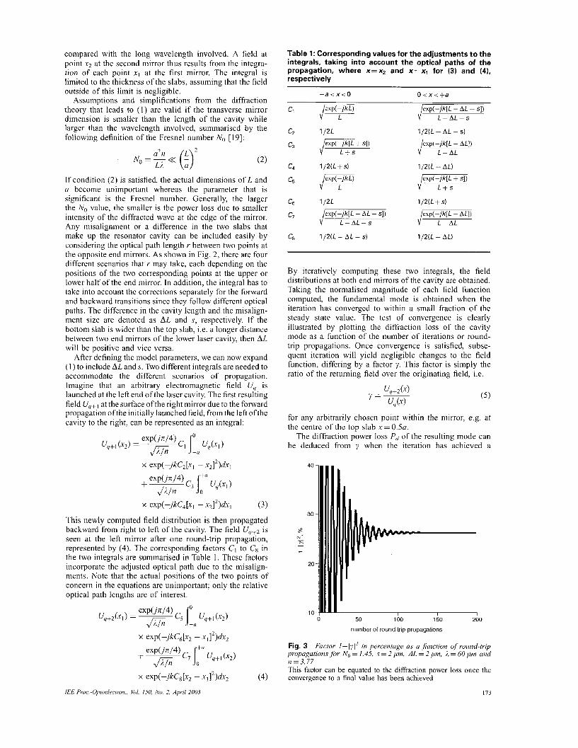
By iterativcly computing these two integrals, the field distributions at both end mirrors of the cavity are obtained. Taking the noinialised magnitude of each field function computed, the fundamental mode is obtained when the iteration has convcrgcd to within a small fraction of the steady state value. The test of convergence is clearly illustrated by plotting the diffraction loss of the cavity mode as a function of the number of iterations or round- trip propagations. Once convergence is satisfied, subse- quent iteration will yield negligible changes to the field Cunction, differing by a factor y. This factor is simply the ratio of the returning field over the originating field, i.e.
( 5 )
for any arbitrarily chosen point within the mirror, e.g. at the centre of the top slab r=0.5a.
The diffraction power loss Pd of the resulting mode can be deduced from Y whcn thc iteration has achicved a
0 50 1 bo 1 so 200
number of round~trip propagations
Fig. 3 Factor 1-1~1~ in prrceiiroge as U firncriun "/round-trip propugations for N,, = 1.45. s = 2 pm, A L = 2 pm, 2 = 60 pm and n=3.77 This factor can be equatcd to the diffraction power loss once the convergence to a final vahie has been achieved
173

reasonable convergence. This relation is given by (6), where 171 is the magnitude of the multiplicative constant:
(6) 2 Pd = 1 ~ 171
Fig. 3 depicts the iteration process, where Pd is plotted as a function of the number of round-trip propagations for an arbitrarily choscn case of No= 1.45, s = 2 pm and AL = 2 Fm. As shown on the figure, the loss value has converged to a final value at about the 130th propagation, where further iteration will bring negligible change to this value. In gencral, our calculation has converged at less than 200 round-trip propagations, although in certain cases more iterations are needed, especially when larger misa- lignment sizes are introduced in the model. The large value (or negative value) oscillation of Pd in the graph at the early stage of the propagation is due to the varying intensity distribution before the steady state is reached.
4 Discussion
Fig. 4 shows, for N " z 2 . 8 2 when i = 6 0 inn, the mode power distribution across the normalised cavity mirror thickness for the different cases of misalignment steps or variation in cavity length. The resulting mode concentrates in the slab with a longer cavity. This will have seriously reduced the mode overlap ratio with the active layers near the centre, x = O . On the other hand, if the two slabs are misaligned the effect on the mode distribution is less obvious. With 3 pm misalignments, the mode shows a rather irregular shape compared with other cases. For x /a > 1, i.e. outside the slabs, the mode intensity is relatively small, thus justifying the model assumption to limit the integral to within f a .
The log-log scale plot of the diffraction power loss against the Fresnel number in Fig. 5 shows decreasing loss for increasing No, consistent with previous results on rectangular mirrors [ 191. The calculated result suggests a high increase in the mode diffraction loss if the misalign- ment step and length variation are more than a few micrometres in size.
0 2 xia
Fig. 4 Calcdafed mode bitensit.v using difruction inregm1 model for. COSP No = 2.82 01 i = 60 ~ t m for diJecrent scenarios qfmisalign- lW2lltS
Graphs arc plotted (normalised and vertically shiflcd for clarity) against normalised slab thickness IJU. J and AL are specified in pm
174
s=1,AL=o + s=o. u = o
1 2 3 4
No
Fig. 5 One-dimensional diflruction p w e y loss pcr mund-(rip propagurion ,for vur-imrr cotabimfions of missrrlignmenr size and diference in caviy lengrh, ploffed against Frewel number. in log- log scale s and AL are in p m
The model has somc numerical issues that prevent useful calculation when certain choices of Fresnel numbers are uscd. An amplitude mismatch in the integrals resulting from (3) and (4) at the interface (r = 0) may occur, which is physically prohibited. The issues can he avoided by choos- ing another value of No, which is close to the original choice if the integral iteration does not converge. This is particularly apparent when the sizes of s and AL are incrcascd.
For the dimensions chosen in Section 3, the correspond- ing Nu is 5.66, which does not satisfy condition (2) very effectively. However, based on the result calculated in Fig. 5, there is sufficient evidence that the diffraction loss is expected to be low if compared to other type of losses. These include the frcc carrier loss and reflection loss.
This approach is also unlikely to be practical for shorter wavelengths in the mid-infrared region, due to the higher accuracies needed for the alignment. Note that this approach is only possible for optically pumped lasers since no electrical current flows across the interface.
5 Conclusions
A novel idea of optically pumping two MQW slabs stacked togethcr with the front sides facing each other, suitable for long wavelength THz semiconductor lasers, is discussed. A critical issue with this pumping scheme is to minimise the misalignment between the two slabs. A model based on diffraction theory is utilised to estimate the additional diffraction loss that may he contributed from the misalign- ment. Results from the model suggest that small misalign- ment in the order of c 4 p , or ahout 7% of the wavelength, can he tolerated. Hence, the stacked scheme is unsuitable for shorter wavelengths in the mid- and near- infrared regions. Despite being unable to obtain the expected diffraction loss value for the case of No=5.66 directly using this model, the results from smaller No
/€E Pruc.-Upro~iecrron.. I,?,/. ISU. h'o. 2, A p d 2003

sufficiently support the argument that the scheme is prac- tical and realisable.
While this paper has been under the publication process, Kohler ef U / . [20] have recently demonstrated the first terahertz quantum cascade laser emitting at 4.4 THz and temperatures up to 50 K.
6 Acknowledgments
This work was supported by the EPSRC. The authors are grateful for the helpful discussion with the devices growers in the University of Sheffield and the Univcrsity of Glasgow. H.A. Tan received a research studentship from the ORC and ORS Awards Scheme.
7 References
I BORENSTAIN, S.I., and KATZ. J.: 'Evaluation ofthc fensihilityofa far- infrared laser hascd on intcrsuhhand transitions in GaAs quantum wells', .4pp/. P h y Leil.. 1989. 55, (7). pp. 654-656
2 AFZALI-KUSHAA, A., HADDAD, G.I., and NORRIS, T.R.: 'Optically pumped intersuhhand lascrs based on quantum wells'. !E,?EJ Q ~ ~ m r u m Elecl~on.. 1995. 31, ( I ) , pp. 135-143
3 SMET. J.H.. FONSTAD. C.G.. and HU, Q.: 'Intrawdl and interwell intersubband transitions in multiplc quantum wel ls for far-infrarcd sources'. J Appi. Pizqn.. 1996, 79. (121, pp. 9305-9320
4 BERGER. V: 'Three-level laser based on intersubband transitions in asymmetric quantum wcIIs: a theorctical study', Seniiconrf. Sci. Techno!., 1994,9, (8). pp. 1493-1499
5 HARRISON. P.. and KELSALL, R.W.: 'Population inversion an opti- cally pumped asymmctnc quantum well terahenz lasers', J Appl. Ph.y.s.,
6 XIN, L J . , and RUTT, H.N.: 'Design of intersubhand quantum well far-infrared Iascrs'. Semicond. Sci. 1997. 12, (9).
7 FAIST, I., CAPASSO, F,, SIVCO, D.L., SIRTORI. C.. HUTCHINSON, A.L., and CHO, A.Y.: 'Quantum cascade laser'. Science. 1994. 264, (5158), pp. 553-556
R JULIEN, EH., SAAR, A., WANG, J., and LERURTON. J.P: 'Optically pumped intersub-band emission in quantum-wells', Eiecimn. Leii.. 1995,31. pp. 838-839
9 GAUTHIER-LAFAYE, O., ROUCAUD, P, JULIEN, F.H., SAUVAGE, S.. CABARET, S., LOURTIOZ, J.M., THIERRY-MIEG, V, and PLANEL. R.: 'Longwavelength (-15.5 wmj unipolar semiconductor lilecr in CvAs quantum wells', Appl. Phr;-. Lett. 1997. 71, (25 ) . 00. 3619-3621
1997.81, (II), pp. 7135-7140
pp. I129-1134
I O EELM. M.. COLAS, E.. ENGLAND, P., DEROSA. F., and ALLEN. S.J.,Jr.: 'Ohselvatinn of grating-induced intersubhand emission from GaAs/AIGaAs superlattices'. Appl. P h w Lett.. 1988. 53, ( I ) . pp. 1714-1716
1 1 COLOMRELLL R., STRAUB, A., CAPASSO. E. GMACHL. C., BLAKEY, M.I.. SERGENT. A.M.. CHU, S.N.G.. WEST, K.W., and PFEIFFER, L.N.: 'Teiahertr electrolumincscencc from superlatticc quantum cascade stm~tures', .I. .Appl. Ph.vs., 2002. 91, (6). pp. 3526-3529
12 ROCHAT, M., FAIST, J.. BECK. M.. OESTERLE. U,. and ILEGEMS, M.: 'Far-infrared (;. = 88 pm) rlsctroluiiiinesfence in a quantum cascade structure'. Appl. Phys. Len, 1998, 73. (25). pp. 37263726
13 KOHLER. R., IOTTI. R.C.. TREDICUCCI, A., and ROSSI. E: 'Design and simulation of terahenr quantum cascade lasers', Appl. f'/t.v.~. Lerr.. 2001. 79. (24). pp. 3920-3922
14 COLOMBELLI, R., CAPASSO, E; GMACHL, C., HUTCHINSON, A.L., SIVCO. D.L., TREDICUCCI, A., WANKE, M.C., SERGENT. A.M., and CHO. A.Y.: 'Far-infrared surface-plasmon quantum-cascade lasers at 21.5 I'm and 24 pm wavelengths'. A/,/,/. P h p LrN, 2001, 78, (18), pp. 2620-2622
15 KINSLER. P. HARRISON. P., and KELSALL. R.W.: 'Intersubband tcmhcrtL lasers using four-level arymmcriic quantum wells'. J. Appl, Ph.v.y., 1999. 85. ( I ) , pp. 23-28
16 XIN. Z.-J.. and RUTT. H.N.: 'Effect o f inhomogeneicy on quantum well far-infrared lasers', J Appl. P h p . 1998, 83, ( 3 ) , pp. 1491-1495
17 XIN. Z.-J., and RUTT. H.N.: 'Inhomogeneous broadcning in quantum well 18ser5'. IiflnraredPhw Techno!., 1999, 40, ( I ) . pp. 3 7 4 0
18 TREDICUCCI, A.. GMACHL, C., WANKE, M.C., CAPASSO, F., HUTCHINSON, A.L., SIVCO, D.L., CHU, S.N.G.. and CHO, A.Y: 'Surface plasmon quantum cascade lasers ai ;. - 19 pm', Appl. 1'hy.s. Lerr., 2000. 77, ( IS) , pp. 2286-2288
19 FOX, A.G., and LI. T.: 'Rcsonast inndei in a m a w interferometer', Bel! Sy~t. Tech. J . 1961, 40, pp. 453-488
20 KOHLER, R.. TREDICUCCI, A.. BELTRAM, F., BEERE, H.E., LINFIELD, E.H., DAVIES. A.G., RITCHIE, D.A., IOTTI, R.C.. and ROSSI. E.: 'Terahenz scmiconductor-heteronructurc. laser', Nature, 2002,417, (6885). pp. 1 5 6 1 5 9
8 Appendix
In the model to calculate the diffraction loss of the resonator cavity, only the relative optical paths are impor- tant. We can write the two dimensional electromagnetic wave at one mirror due to the propagation of an original wave from the opposite mirror as [19]:
where r is the optical path, .r and y are the two dimensions of the mirrors, and z is the distance between the two points of interest, as shown in Fig. 2.
For a perfectly aligned case, z= L and
(8) LL
L A 2 exp(-jkr) = exp ~ +- exp -+- ( 4 E*) (2 2 L )
where Ar and Ay are the differences between the two points in the x- and y-axis, respectively. As we are only interested in the x-dimension, we can write [I91
U&.Y) = U&W&,v) (9) and substitute (8) into (7) to obtain:
where 26 is the length of the slab. Consequently, the optical paths for our model can be easily derived by considering the changes due to s and AL as:
The entries in Table I can thus he extracted by substituting the relevant r and z from (11) into the integrals (3) and (4), and taking only the dimension of intcrest.


![Graphene modelocked VECSELs · Ultrafast vertical-external-cavity surface -emitting lasers (VECSELs )[4], also known as semiconductor disk lasers (SDLs) [5] or optically pumped semiconductor](https://img.pdfslide.us/doc/110x75/5f09805b7e708231d4272096/graphene-modelocked-vecsels-ultrafast-vertical-external-cavity-surface-emitting.jpg)


![Lau, Stephan; Petković, Bojana; Haueisen, Jens · Magnetoresistive (MR) sensor technologies [4–8] as well as optically pumped magnetometer technologies [9–13] have reached sensitivities](https://img.pdfslide.us/doc/110x75/5d4cbc7c88c9932a0a8b7311/lau-stephan-petkovic-bojana-haueisen-jens-magnetoresistive-mr-sensor.jpg)


![proc]_optically_pumped_mx... · strength is provided nowadays by quantum magnetometers based on the Zeeman effect in radio-¾xctra of nuclei and atoms. The optically pumped potassium](https://img.pdfslide.us/doc/110x75/5e480b8d7dbe47056e30b9f8/procopticallypumpedmx-strength-is-provided-nowadays-by-quantum-magnetometers.jpg)