Embed Size (px)
Citation preview

Bosch Rexroth Oil Control S.p.A.RE 90010-05/07.2012
For the latest product information from Bosch Rexroth, please visit our website:www.boschrexroth.com/products
Designation Data sheet Pages
Common cavities and tooling RE 18325-70 1551
Special cavities RE 18325-75 1557
Cavities
81549

Bosch Rexroth Oil Control S.p.A. RE 90010-05/07.2012
1550

1/6
Common cavities and tooling
2-way
3-way / 3-way short
4-way
RE 18325-70/07.12Replaces: RE 18325-70/02.10
Summary
Description Page
Common cavity 2-way
CA-08A-2N 2CA-10A-2N 2CA-12A-2N 2CA-16A-2N 2CA-20A-2N 2Tools 2
Common cavity 3-way short
CA-08A-3C 3CA-10A-3C 3CA-12A-3C 3CA-16A-3C 3CA-20A-3C 3Tools 3
Description Page
Common cavity 3-way
CA-08A-3N 4CA-10A-3N 4CA-12A-3N 4CA-16A-3N 4CA-20A-3N 4Tools 4
Common cavity 4-way
CA-08A-4N 5CA-10A-4N 5CA-12A-4N 5CA-16A-4N 5CA-20A-4N 5Tools 5
81551

RE 18325-70/07.122/6 Bosch Rexroth Oil Control S.p.A.
Common cavities - Tools2-way 1 mm = 0.03937 in
1 in = 25.4 mm
1552

RE 18325-70/07.12 Bosch Rexroth Oil Control S.p.A. 3/6
Common cavities - Tools3-way short 1 mm = 0.03937 in
1 in = 25.4 mm
81553

RE 18325-70/07.124/6 Bosch Rexroth Oil Control S.p.A.
Common cavities - Tools3-way 1 mm = 0.03937 in
1 in = 25.4 mm
1554
RE 18325-70/07.12 Bosch Rexroth Oil Control S.p.A. 5/6
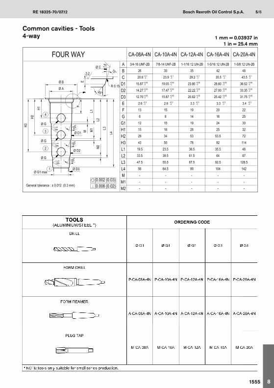
Common cavities - Tools4-way 1 mm = 0.03937 in
1 in = 25.4 mm
81555

RE 18325-70/07.126/6 Bosch Rexroth Oil Control S.p.A.
Bosch Rexroth Oil Control S.p.A.Via Leonardo da Vinci 5P.O. Box no. 541015 Nonantola – Modena, ItalyTel. +39 059 887 611Fax +39 059 547 [email protected]
© This document, as well as the data, specifications and other information set forth in it, are the exclusive property of Bosch Rexroth Oil Control S.p.a.. It may not be reproduced or given to third parties without its consent.
The data specified above only serve to describe the product. No statements concerning a certain condition or suitability for a certain application can be derived from our information. The information given does not release the user from the obligation of own judgment and verification. It must be remembered that our products are subject to a natural process of wear and aging.
Subject to change.1556

1/8
Special cavities
004 - 008 - 009 - 065 - 308 - 348 - 690730 - 730-A - 808 - 869 - 870 - 871 - 924CA-07A-3N - CA-04A-3Y - CA-16A-5C - CA-20B-6C017-E - 019-E - 021-E - 076-E - 081-E
RE 18325-75/07.12Replaces: RE 18325-75/04.11
Summary
Description PageCavity 004 2Cavity 008 2Cavity 009 2Cavity 065 2Cavity 348 2Cavity 690 2
Cavity 730 3Cavity 730-A 3Cavity 808 3Cavity 869 3Cavity 870 3Cavity 871 3
Description PageCavity 924 4Cavity CA-07A-3N 4Cavity CA-04A-3Y 4
Cavity 308 4
Cavity CA-20B-6C 5
Cavity 017-E 6Cavity 019-E 6Cavity 021-E 6Cavity 076-E 6Cavity 081-E 6
Cavity CA-16A-5C 7
81557
RE 18325-75/07.122/8 Bosch Rexroth Oil Control S.p.A.
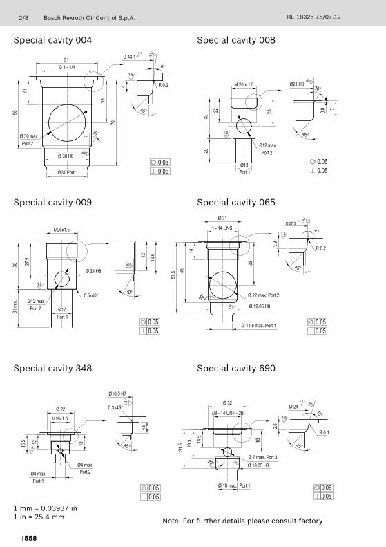
1 mm = 0.03937 in1 in = 25.4 mm
Special cavity 004
Special cavity 009
Special cavity 348
Special cavity 008
Special cavity 065
Special cavity 690
Note: For further details please consult factory
1558

RE 18325-75/07.12 Bosch Rexroth Oil Control S.p.A. 3/8
1 mm = 0.03937 in1 in = 25.4 mm
Special cavity 730
Special cavity 808
Special cavity 870
Special cavity 730-A
Special cavity 869
Special cavity 871
Note: For further details please consult factory
81559
RE 18325-75/07.124/8 Bosch Rexroth Oil Control S.p.A.
1 mm = 0.03937 in1 in = 25.4 mm
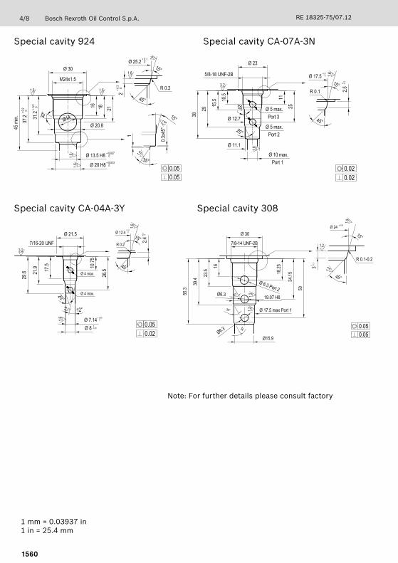
Special cavity 924
Special cavity CA-04A-3Y Special cavity 308
Special cavity CA-07A-3N
Note: For further details please consult factory
1560

RE 18325-75/07.12 Bosch Rexroth Oil Control S.p.A. 5/8
1 mm = 0.03937 in1 in = 25.4 mm
Special cavity CA-20B-6C
Note: For further details please consult factory
81561

RE 18325-75/07.126/8 Bosch Rexroth Oil Control S.p.A.
1 mm = 0.03937 in1 in = 25.4 mm
Special cavity 017-E
Special cavity 021-E Special cavity 076-E
Special cavity 019-E
Special cavity 081-E
Note: For further details please consult factory
1562

RE 18325-75/07.12 Bosch Rexroth Oil Control S.p.A. 7/8
Special cavity CA-16A-5C
Note: For further details please consult factory
81563

RE 18325-75/07.128/8 Bosch Rexroth Oil Control S.p.A.
Bosch Rexroth Oil Control S.p.A.Via Leonardo da Vinci 5P.O. Box no. 541015 Nonantola – Modena, ItalyTel. +39 059 887 611Fax +39 059 547 [email protected]
© This document, as well as the data, specifications and other information set forth in it, are the exclusive property of Bosch Rexroth Oil Control S.p.a.. It may not be reproduced or given to third parties without its consent.
The data specified above only serve to describe the product. No statements concerning a certain condition or suitability for a certain application can be derived from our information. The information given does not release the user from the obligation of own judgment and verification. It must be remembered that our products are subject to a natural process of wear and aging.
Subject to change.
1564

1/12
Technical data
RE 18350-50/07.12
Introduction:Do not apply the below technical data to the following sections:
High pressure cartridge valves and Proportional pressure reducing valves & Remote control manifolds (RE 90010-05 • chapter 5 and 6). Please refer to the information included on the individual data sheet and/or contact the sales network indicated on it for any doubts.Compact Directional Valves (RE 90010-06 chapters 2, 3, 4 and 5). Please refer to the information included on the • individual data sheet for technical and usage details and/or contact the sales network indicated on it for any doubts.Compact Power Modules (RE 90010-06 chapter 6). Please refer to the information included on the individual data • sheet for technical and usage details and/or contact the sales network indicated on it for any doubts.
1. GeneralBosch Rexroth Product Area 2 - Compact Hydraulics (CH) proposes a wide range of hydraulic components for applications in hydraulic circuits of mobile and industrial machinery. Detailed information about product performance, selection, installation and technical data can be obtained from our Customer Service Organization; here you may find a summary of general specifications which apply to all our CH hydraulic products with the aim to provide general guidance only.
2. Hydraulic fluidsMineral oil based hydraulic fluids suitable for hydraulic systems can be used; they should have physical lubricating and chemical properties as specified by:
MINERAL OIL BASED HYDRAULIC FLUIDS HL (DIN 51524 part 1)• MINERAL OIL BASED HYDRAULIC FLUIDS HLP (DIN 51524 part 2).•
For use of environmentally friendly fluids (vegetable or polyglycol base), or other fluids, please consult CH.
2.1 Fluid viscosityWhen not differently specified in the individual data sheet, the fluid viscosity should remain within the range 3 to 400 cSt (centistokes). Hydraulic fluids are available in different viscosity classes identified by the ISO VG number, which corresponds to the kinematic viscosity at 40°C (104°F). Here is a table showing typical viscosity changes between 0°C and 100°C (32°F and 212°F) for mineral oil based fluids having various viscosity classes. The fluid should be selected with the aim to achieve an appropriate operating viscosity at the expected working temperatures.
VISCOSITY CLASSKINEMATIC VISCOSITY - (cSt)
MAX at 0°C (32°F) MED at 40°C (104°F) MIN at 100°C (212°F)
ISO VG 10 90 10 2.4
ISO VG 22 300 22 4.1
ISO VG 32 420 32 5
ISO VG 46 780 46 6.1
ISO VG 68 1400 68 7.8
ISO VG 100 2560 100 9.9
Note: all main performance curves and specifications shown in CH technical literature are obtained using mineral based fluid ISO VG 46, i.e. 46 cSt at 40°C (104°F), with an oil temperature of 30-40°C (86-104°F).More detailed technical characteristics are available at CH.
1565

2/12 Bosch Rexroth Oil Control S.p.A. RE 18350-50/07.12
TYPE OF SYSTEMTYPE OF VALVE
OIL FILTRATION RECOMMENDATIONS
Cleanliness classrecommended Absolute fi ltration
(micron rating)( ** )ISO
4406 : 1999NAS 1638
( * )
Systems / components operating atHIGH PRESSURE > 250 bar (3600 psi)
HIGH DUTY CYCLE APPLICATIONSSystems / components with LOW dirt tolerance
18 / 16 / 13 7 - 8 5
Systems / components operating atMEDIUM HIGH PRESSURE
Systems / components with moderate dirt tolerance19 / 17 / 14 9 10
Systems / components operating atLOW PRESSURE < 100 bar (1500 psi)
LOW DUTY CYCLE APPLICATIONSSystems / components with GOOD dirt tolerance
20 / 18 / 15 10 - 11 20
2.2 Fluid temperature recommendationCH components are generally equipped with BUNA-N seals and, for this reason, the fl uid temperature should remain within the -30°C and +100°C range (-22°F and +212°F). In case of temperatures outside this range, consult CH.
2.3 Fluid cleanliness requirementsThe cause of malfunctions in hydraulic systems and components is often found to be excessive fl uid contamination. The hard contaminant particles in the fl uid wear the hydraulic components and prevent the poppets from re-seating, with consequent internal leakage and system ineffi ciency. For the correct operation of CH components it is necessary to adopt fi ltration methods which guarantee for life the specifi ed fl uid cleanliness level. It is important to ensure that hydraulic fl uids are brought to the appropriate cleanliness level prior fi lling up the systems, and, when in doubt, also to fl ush the hydraulic components prior to installation. Fluid fi ltration must comply with the specifi cations given by following table, where diff erent cleanliness measuring standards are mentioned.ISO 4406:1999 presently is the preferred standard; it defi nes the fl uid cleanliness by three numbers respectively representing the maximum number of particles larger than 4μm, 6μm and 14μm contained in one ml of fl uid.
(*) Contamination class NAS 1638 (National Aerospace Standard, conceived in the early 60’s, officially superseded since June 2001): it is still followed and it is determined by counting the total particles of different size ranges contained in 100 ml of fluid.
(**) Absolute filtration: is a characteristic of each type of filter; approximately, it refers to the size (expressed in microns) of the largest spherical particle which may pass through the filter.
1566

RE 18350-50/07.12 Bosch Rexroth Oil Control S.p.A. 3/12
CHART OF SEALING PROPERTIES
HYDRAULIC FUNCTION Valve typeFlow
l/min (gpm)Max pressure
bar (psi)Operation type Average leakage
Pressure relief Direct acting poppet type(leak proof seat design)
3-30(1-8)
350(5000)
CONTINUOUS 5-10 drops at 80% ofstd pressure setting
(Z=20-35)(max 40 drops/min)
Direct acting differential type(leak proof seat design)
40-350(11-93)
350(5000)
INTERMITTENT
Direct acting poppet type20-200(5-53)
350(5000)
CONTINUOUS5-10 cm3/min (0.31-0.61 in3/min)
at 80% of std pressure setting (Z=20-35)
Pilot controlled spool type150(40)
420(6000)
CONTINUOUS100 cm3/min (6.1 in3/min) at 90%
of std pressure setting
Check valve Poppet type(leak proof seat design)
30-100(8-26)
350(5000)
CONTINUOUS0-5 drops/min
(max 20 drops/min)Ball type(leak proof seat design)
60(16)
350(5000)
INTERMITTENT
Pilot assistedcounterbalance
30-320(8-85)
350(5000)
CONTINUOUS5-10 drops/min at 80% of
pressure setting(max 40 drops/min)
3. Internal leakage Here is a table with general information about the sealing properties of CH valves and components with leak proof seat design; the allowed leakage tolerance may change depending on the design, number of poppets and valve size; this general information is given for guidance only and, for many valves, specific details about the permissible leakage tolerance can be found in the relevant data sheet.The AVERAGE LEAKAGE for different valve families is expressed in cm3/min, or drops/min and is measured in the specified test conditions. The ratio between cm3 and drops is approximately: 1 cm3 (or 0.06 in3) = 15 – 18 drops.For pressure relief valves the leakage is indicated at re-seating conditions, identified as X% of pressure relief setting.
4. Pressure settingCH valves are supplied pre-set at the standard pressure setting shown by the relevant catalogue sheet.Whenever the application requires a re-adjustment, please ensure that the limits of the indicated pressure range and maximum working pressure are never exceeded.
5. Sealing of valve adjustersSpecial plastic sealing caps for service are available for most CH valves and cartridges. Upon request, valves can be supplied factory sealed.
6. Storage of new componentsThe components shall not be exposed to direct sun light nor to sources of heat or ozone (like electric motors running), and should be stored in their original, protective packing at ambient temperature within the range -20°C and +50°C (-4°F and 122°F).
7. PortsG type ports (ISO 228-1) are often standard on components with body for line connection; SAE sizes (straight thread), JIS or metric ports can be manufactured upon request.
1567

4/12 Bosch Rexroth Oil Control S.p.A. RE 18350-50/07.12
8. Body materialsValves and integrated manifolds for high pressure and/or heavy duty applications are • manufactured with high quality leaded steel, zinc plated with yellow trivalent chrome treatment.Valves and integrated manifolds for medium working pressure (up to 210 bar) can be made of • high strength wrought aluminium, black anodized upon request.Housings for modular, solenoid operated directional valves and flow diverters are made of high • strength cast iron, zinc plated with yellow trivalent chrome treatment.
9. SealsO-Rings: Buna N (acrylonitrile butadiene), also named NBR (according to ASTM), compatible with fluids having mineral oil base, water-in-oil emulsions, and water-glycol fluids. These seals are standard for temperatures within the range -30°C and +100°C (-22°F and +212°F).Back-up rings and Slide rings: strengthened PTFE (Politetrafluoroetilene like Teflon®, Lubriflon®, Ecoflon®, or similar).Special FPM (Viton®) seals are available on request.Note: the seal materials are compatible with the fluids normally used in hydraulic systems; in case of special fluids, if you suspect incompatibility between the fluid used and the standard seals, contact the CH service network.
9.1 Seal kitsfor cartridge valves: the kits include all the external seals;• for components assembled as parts in bodies or housings: the kits include all external seals for • flange fitting, or for matching different units together.
10. InstallationEnsure that all matching surfaces are clean, without contamination.• Ensure that all seals and back-up rings for the matching surfaces are flawless and correctly • placed.Do not put any sealing material other than the standard seals.• Place in position the valve, then, by hand, insert the fittings and the locating screws. • In case of cartridge valve, check that the cavity is clean, without sharp edges or chips. Dip the • cartridge in clean oil, then insert it into the cavity and screw it in by hand, until you begin to compress the top O-Ring.Finally tighten with a calibrated torque wrench and torque up to the specifications shown in the • catalogue.
11. Cavities for screw-in cartridgesCH has developed a complete range of cartridges which fit the cavity patterns with UN/UNF threads, according to SAE standards, nominal sizes 08-10-12-16-20. Internal parts of cartridges are designed with a global view of our comprehensive variety of hydraulic products; accordingly, our technology has been optimized in order to employ few basic parts for many different valves for best reliability, cost effectiveness and availability. Further, we can propose our cartridges in different versions, with a variety of external shells in order to fit other cavity patterns, such as ISO/METRIC, or special industrial patterns.
1568

RE 18350-50/07.12 Bosch Rexroth Oil Control S.p.A. 5/12
12. Coils
12.1 Coil installation on solenoid cartridges
12.2 Working duty (DIN VDE 0580)The working duty ED of a coil is the ratio between energized time ti and full cycle time tc wheretc = ti + tr, and tr = de-energized time.
ED = ( ti / tc ) • 100%All CH coils are rated for ED = 100% (i.e. always energized), provided that the temperature limits of their insulation classes are not exceeded.
12.3 Protection rating (DIN 40050 - Part 9 IEC 60529)Protection class is designated by the letter IP followed by two digits: the first digit refers to resistance against penetration of surrounding or foreign solid objects, the second against penetration of water. Protection class doesn’t apply to explosion risks or to conditions such as moisture, corrosive agents, mildew etc.
IP65• means water protection against LOW PRESSURE JETS:water at 0.3 bar (43.5 psi ) pressure sprayed from a distance of 2.5 – 3 m (8.2 – 9.8 ft) from every directionIP65 coils CANNOT BE PLUNGED INTO WATER OR REMAIN UNDER WATER.IP67• means water protection against 30 MINUTES IMMERSION under water 1 m (3.3 ft) deep.IP69K • means water protection against HIGH PRESSURE JETS:
water at high pressure and temperature, 80-100 bar (1160–1450 psi) and 75-85°C (167°F-185°F), sprayed from a distance of 100–150 mm (3.9–5.9 in) from every direction.
COIL INSTALLATIONCOIL WITH O-RING SEATS (S7-S5-R7)
It is recommended to follow these steps:• Insert 1st O-Ring (see drawing)• Insert coil• Insert 2nd O-Ring (see drawing)• Tighten BY HAND coil retaning nut to the • torque specifi ed in the cartridge catalogue page.
OIL WITHOUT O-RING SEATS (S8-356)It is recommended to follow these steps:• Insert 1st O-Ring (see drawing)• Insert coil• Tighten BY HAND coil retaining nut to the • torque specifi ed in the cartridge catalogue page. The 2nd O-Ring is fi xed inside the nut.
IMPORTANT: O-Rings are the only protection against water infi ltration between tube and coil, which may lead in short time to coil failure. The proper mounting of both O-Rings is therefore necessary to ensure normal life of coils when operating in presence of water, ice, moisture etc. Oil Control cannot guarantee any IP protection degree if both O-Rings are not properly mounted on coils.
1st O-Ring
Nut
2nd O-Ring
Coil
1st O-Ring
Nut
2nd O-Ring
Coil
Nut Nut
2nd O-Ring 2nd O-Ring
CoilCoil
1st O-Ring
1st O-Ring
1569

6/12 Bosch Rexroth Oil Control S.p.A. RE 18350-50/07.12
12.4 Coil resistance to thermal shock dunk testThis test, well known and commonly applied in the construction, agricultural and mobile equipment markets, includes several steps :1) Coil is maintained energized for 1 hour at nominal voltage and ambient temperature 25°C (77°F), or is not energized but heated for 2 hours in oven at 105°C (221°F).2) Coil is immediately immersed in water at 20 - 25°C (68 – 77°F) for 30 minutes, at minimum depth 300 mm (11.8 in).3) Coil, when still wet, is tested for moisture ingression and dielectric breakdown with a dielectric tester, like the “Hypot”. With this tester, a voltage differential of 500V DC is applied between the winding and the coil external surface in order to measure the current leakage which must not exceed 100μA (micro-amps).4) The complete test is performed on samples of 10 coils minimum, and is repeated at least five times. All coils with EN 175301-803 (ex DIN 43650) connector correctly mounted comply with IP65 protection class.Coils with integrated Deutsch DT04-2P connector have IP69K protection class, and pass the thermal shock dunk test.
12.5 Heat insulation (DIN VDE 0580)The actual coil temperature T is the result of (TA + ΔT), where:TA = ambient temperature, and ΔT = temperature rise due to coil operation.Example: with TA = 40°C (104°F) and ΔTmax = 115°C (239°F ), T = 155°C (311°F); with TA = 40°C (104°F) and ΔTmax = 140°C (284°F), T = 180°C (365°F).The coil ΔT is determined following a standard procedure (DIN VDE 0580):
the coil is mounted on a standard cartridge, inserted in a standard steel manifold placed on a • wooden surface.the coil is maintained energized for 1 hour at nominal voltage, with ambient temperature TA = • 20-25°C (68-77°F) and with natural ventilation.
CLASS H coils are rated for T max = 180°C (356°F): if ambient temperature exceeds the value Tx = 180°C (356°F) - ΔT, a class H coil cannot be used under continuous duty cycle (ED = 100%); the coil must be periodically de-energized to prevent exceeding the MAX temperature.In any case, for the correct operation of coils, it is always necessary to provide means for heat dissipation and, at least, natural ventilation.
Caution: when energized, the coil surface temperature can reach quickly (in few minutes of continuous operation) temperature levels of 80-100°C (176-212°F), which is not directly related to the coil ΔT:care should be taken to avoid any accidental contact of people with the coil surface.
12.6 AC ServiceAll CH solenoid valves are designed to operate exclusively with DC power supply. All coil windings are DC.AC operation is possible using EN 175301-803 (ex DIN 43650) connectors with rectifier.
1570

RE 18350-50/07.12 Bosch Rexroth Oil Control S.p.A. 7/12
12.7 Optional manual emergency for solenoid cartridgesUpon request, the solenoid cartridges can be equipped with tubes incorporating a manual emergency device for valve operation when the coil cannot be energized, like in case of voltage shortage. Here is a summary of the different options available:
AVAILABLE ON FOLLOWING MODELS:2 way 2 position pilot operated normally closed series 8A / 8I• 2 way 2 position direct acting poppet style normally closed series 8I• 2 way 2 position direct acting double lock normally open series 8I• 3 way 2 position spool style series 8I / 7I• 4 way 2 position spool style series 8I / 7I•
OPERATIONTo operate manual override, screw out the knob turning it counterclockwise.To return to normal valve operation, turn the knob clockwise.
AVAILABLE ON FOLLOWING MODELS:Proportional valves series 5A•
OPERATIONTo operate manual override, screw in the pin turning it clockwise withwrench.To return to normal valve operation, turn the bolt counterclockwise.
AVAILABLE ON FOLLOWING MODELS:2 way 2 position pilot operated normally open series 8A / 8I• 2 way 2 position direct acting poppet style normally open series 8I• 2 way 2 position direct acting double lock normally closed series 8I•
OPERATIONTo operate manual override, push and hold override button.To return to normal valve operation, simply release the button.
AVAILABLE ON FOLLOWING MODELS:2 way 2 position direct acting double lock normally closed series 7A• 3 way 2 position direct acting poppet style series 7A•
OPERATIONTo operate manual override, push and hold override button with tool.To return to normal valve operation, simply release the button.
AVAILABLE ON FOLLOWING MODELS:2 way 2 position pilot operated normally open series 8A / 8I• 2 way 2 position direct acting poppet style normally open series 8I• 2 way 2 position direct acting double lock normally closed series 8I•
OPERATIONTo operate manual override button, turn clockwise and release.To return to normal valve operation, push override button, turn counterclockwise and release.
AVAILABLE ON FOLLOWING MODELS:4 way 3 position spool style series 8A / 7I•
OPERATIONTo operate manual override, push to override S2 coil or pull to overrideS1 coil and hold override button.To return to normal valve operation, simply release the button.
SCREW-OUT KNOB STYLE
SCREW-IN STYLE
PUSH STYLE
PUSH AND TWIST STYLE
PUSH AND PULL STYLE
1571

8/12 Bosch Rexroth Oil Control S.p.A. RE 18350-50/07.12
AVAILABLE ON FOLLOWING MODELS:2 way 2 position pilot operated normally closed series 8A size 06•
OPERATIONTo operate manual override, pull and hold the knob. This override is not detented. Force required to operate is approximately 50 N (11.2 lbs).This override can also be remote operated by a cable fi xed to the M8 thread. In this case the spring may not provide enough force to overco-me internal cable friction and the user must provide an external means of returning the cable.
AVAILABLE ON FOLLOWING MODELS:• 2 way 2 position pilot operated normally open series 8A / 8I• 2 way 2 position direct acting poppet style normally open series 8I• 2 way 2 position direct acting double lock normally closed series 8IOPERATIONTo operate manual override, screw out the knob protection after remo-ving wire-locking and push and hold override button. To return to normal valve operation, simply release the button.
AVAILABLE ON FOLLOWING MODELS:2 way 2 position pilot operated normally open series 8A / 8I• 2 way 2 position direct acting poppet style normally open series 8I• 2 way 2 position direct acting double lock normally closed series 8I•
OPERATIONTo operate manual override, screw out the knob protection after removing wire-locking and turn clockwise and release override button.To return to normal valve operation, push override button, turn counterclockwise and release.
SCREW-OUT KNOB STYLE
SAFETY PUSH STYLE
CABLE OPERATED
HANDOPERATED
SAFETY PUSH AND TWIST STYLE
1572

RE 18350-50/07.12 Bosch Rexroth Oil Control S.p.A. 9/12
13. Technical data for Proportional valves CH
GLOSSARY OF TERMS AND DEFINITIONS
Current is the flow of electrons in a conductor, measured in Amperes (A) or milli-amperes (mA) and abbreviated “I”.
Voltage is the potential for current flow in an electrical circuit. It is measured in Volts (V) and abbreviated “V.”
Resistance is a material’s opposition to the flow of electrical current. It depends on physical properties as well as temperature, size and shape of the material. It is measured in Ohms (Ω) and abbreviated “R”. The tolerance allowed on resistance at ambient temperature 20-25°C (68 - 77°F) is ± 7 %.
Hysteresis is the diff erence in regulated hydraulic parameter (fl ow / pressure) at a fi xed current level when current is increasing vs. when current is decreasing. It is normally expressed as a percentage of the total change in regulated hydraulic parameter (fl ow / pressure).Example: With 900 mA input current and increasing current, 20 bar (290 psi) regulated pressure is achieved. With 900 mA input current and decreasing current, 20.8 bar (302 psi) regulated pressure is achieved. There is a 0.8 bar (12 psi) diff erence in regulated pressure achieved with the same current depending on whether current is increasing or decreasing.If Maximum Regulated Pressure = 25 bar (363 psi) and Minimum Regulated Pressure = 4 bar (58 psi), the total regulated parameter change is 25 (363) – 4 (58) = 21 bar (305 psi).Hysteresis = (0.8 / 21) x 100 = 3.8%.
Proportional Controller is a device that converts a low-power input signal into an output signal that is capable of operating the valve. This output signal can be modifi ed to include PWM, ramping, etc.Pulse Width Modulation (PWM) is a method used to vary the average current induced in a coil using a square wave of fi xed frequency, and variable ratios of on/off times.
Dither is a method used to reduce hysteresis by applying a square or triangle wave to the coil voltage. It can be applied to straight DC or PWM.
Maximum Control Current is the point where increasing current input no longer results in an increase in regulated hydraulic parameter (flow / pressure).
I-Min and I-Max represent the minimum and maximum control current induced into a proportional valve coil. The tolerance allowed is ± 10 % and depends largely from coil´s resistance tolerance.
Ramping is the ability to control the rate of change of the output of an electronic controller.
VERY IMPORTANT:a. It is strongly recommended to use pulse-width-modulation (PWM) as input signal to coils rather than
straight DC. Our tests indicate that PWM input signal allows best valve performance, significantly reducing hysteresis and response times of all our proportional valves. All features shown and explained in next pages are available from many industry-common electronic controllers, including Proportional Controllers described in this catalogue.
b. CH recommends to use always 12 V DC coils in combination with 24 V DC supply voltage to the electronic controller. This allows to use a much wider control current range independently from coil temperature, since anyway current is regulated by the electronic controller and there is no coil overheating risk.
1573

For normally closed proportional valves, the hysteresis curve with increasing current is always lower than the curve with decreasing current. The opposite is true for normally open proportional valves as shown.
An important control feature of electronic controllers is I-Min / I-Max adjustment. This feature allows control of the regulated hydraulic parameter across the full range of the electronic controller by eliminating deadband.
Many commercially available controllers also offer a ramping control feature. This feature allows to adjust the current rate of change between the I-Min and I-Max setpoints.
On Time=Off Time 50% Induced current
80% On Time 80% Induced current
10% On Time 10% Induced current
PULSE WIDTH MODULATION
HYSTERESIS CHARACTERISTIC WITH 120 Hz PWM
NC Valves NA Valves
REPEATABILITY RANGE
IMin Adjustments
IMAX Adjustments
Ramp up
Ramp down
RAMP SLOPE CONTROL
10/12 Bosch Rexroth Oil Control S.p.A. RE 18350-50/07.12
14. European machine directive 2006/42/CEThe CH valves or components described in this catalogue can be employed in machinery or systems which need to comply with the European Machine Directive In such case, the CH valves, manifolds, components and assemblies must be fitted in compliance with all the relevant technical data sheet applicable to the product, and shall not be operated, adjusted or disassembled before the complete machinery where they are incorporated has been declared to be in compliance with the Machine Directive 2006/42/CE.
PULSE WIDTH MODULATION
HYSTERESIS CHARACTERISTIC WITH 120 Hz PWM
For normally closed proportional valves, the hysteresis curve with increasing current is always lower than the curve with decreasing current.
The opposite is true for normally open proportional valves as shown.
On Time = Off Time50% Induced current
NC Valves
I-MinAdjustments
I-MAXAdjustments
Rampup
Rampup
Rampdown
NA Valves
80% On Time80% Induced current
10% On Time10% Induced current
An important control feature of electronic controllers is I-Min / I-Max adjustment.
This feature allows control of the regulated hydraulic parameter across the full range of the electronic controller by eliminating deadband.
Many commercially available controllers also offer a ramping control feature.
This feature allows to adjust the current rate of change between the I-Min and I-Max setpoints.
REPEATABILITY RANGE
RAMP SLOPE CONTROL
1574

RE 18350-50/07.12 Bosch Rexroth Oil Control S.p.A. 11/12
15. General technical data for compact power modules
Through the years DCOC has developed a highly evolved modular system resulting in powerful, flexible and cost effective power pack range, identified as “compact power modules”. In its easier configuration, a “compact power module” is an assembly of electric motor, central manifold with valves, pump, oil tank and a few connection elements. The central manifold, with its built-in valves, allows to achieve a large variety of hydraulic control circuits. If more complex circuits are needed, modular integrated blocks can be added by flange mounting, or interfacing, to the central manifold to extend its capabilities.
15.1 Power module selection
Choose the circuit which meets your application requirements• .Take note of all dimensions resulting from the basic components chosen for your application.• NOTE: dimensions may vary slightly and should be confirmed by DCOC, if the assembly is to be installed in a space with narrow clearance.The tank capacity and the tank dimensions need to be large enough to assure proper pump suction: there • must always be a reserve of oil in the tank when all cylinders are fully extended and avoid overflow when cylinders are fully retracted. The tank must be evaluated also for best separation of air from oil, and for settling down oil contamination. It • should be placed in a space with, at least, natural ventilation and it should permit enough heat dissipation to prevent fluid temperature from exceeding 60°C (140°F). Select the electric motor by evaluating the power needed and the motor compliance with the heat developed • during the expected run time (or “duty cycle”).Motor performance diagrams for “continuous running” (S1), “short time running” (S2) or “intermittent periodic running” (S3) are available in the catalogue. In case of doubt, consult DCOC.
15.2 Power module installation
The mounting position is basically un-restricted; just avoid installations that could compromise the pump suction. It is recommended to support the power module on vibration dampening blocks when the mounting structure is expected to vibrate.
15.3 Hydraulic fluid for power module
It should meet all specifications given for the other DCOC valves and components, except that:the viscosity• should remain within the range 10 to 300 cSt (centistokes); best 15 to 120 cSt.the temperature• should remain within the range -15°C and +80°C (5°F and176°F). In fact, these are the temperature limits generally recommended for the gaskets employed in these power modules.
15.4 Cleaning and maintenance
All components of the hydraulic circuit, including hoses and actuators, must be flushed clean before assembling, because the power module only has a suction filter.The hydraulic fluid should be replaced after the first 100 hours, and then every 3000 hours, or, at least, once a year.
15.5 Wiring and starting-upThe wiring between battery and electric motor should be selected in order to avoid excessive voltage drop (recommended less than 1 V).It is strictly forbidden to allow the backwards rotation of the pump even at the first starting: to prevent reverse rotation, the wiring polarities must be correctly connected.
Caution: when energized, the surface temperature of the electric motor could reach temperature levels of 60–80°C (140–176°F): care should be taken to avoid any accidental contact of people with the motor surface.
1575

12/12 Bosch Rexroth Oil Control S.p.A. RE 18350-50/07.12
© This document, as well as the data, specifications and other information set forth in it, are the exclusive property of Bosch Rexroth Oil Control S.p.a.. It may not be reproduced or given to third parties without its consent.
The data specified above only serve to describe the product. No statements concerning a certain condition or suitability for a certain application can be derived from our information. The information given does not release the user from the obligation of own judgment and verification. It must be remembered that our products are subject to a natural process of wear and aging.
Subject to change.
Bosch Rexroth Oil Control S.p.A.Via Leonardo da Vinci 5P.O. Box no. 541015 Nonantola – Modena, ItalyTel. +39 059 887 611Fax +39 059 547 [email protected]
1576

RE 18350-80/07.12 Bosch Rexroth Oil Control S.p.A. 1/12
Code Index – Product Catalog Mobile Hydraulics, Part 5Compact Hydraulics: Mechanical, solenoid and proportional cartridge valves,hydraulic integrated circuits
040103X5600 STVU-08A RE 18321-10 245
040105X8500 STVU-10A RE 18321-11 247
040106X5600 STFU-08A RE 18321-09 249
0402010056Z VRFA-08A RE 18321-12 251
0402010085Z VRFA-10A-TF RE 18321-13 253
040201X85Z VRFA-10A RE 18321-15 255
040202X85Z VRFB-10A RE 18321-16 257
0402030057Z VRFA-12A-TF RE 18321-14 259
0404010085Z VRFC-10A-TF RE 18321-18 263
040401X85Z VRFC-10A RE 18321-17 265
040402X85Z VRFD-10A RE 18321-20 267
0404030057Z VRFC-12A-TF RE 18321-19 269
0404040085Z DSDN-10A RE 18321-22 273
040404X57Z VRFD-12A RE 18321-21 271
0405010085Z DRFN-10A RE 18321-24 277
0405020027Z DRFN-16A RE 18321-25 279
0405030027Z DSDN-16A RE 18321-23 275
040701X57Z VRFE-12A RE 18321-30 261
041105X99Z VS-80 RE 18318-25 53
041118X09Z VS-30-NCF RE 18318-24 51
041118X99Z VS-30 RE 18318-23 49
041127X99Z VS-30-CC RE 18318-26 65
041148X56Z VSAN-08A RE 18318-01 41
041149X20Z VSBN-08F RE 18318-18 45
041149X56Z VSBN-08A RE 18318-04 43
041155X85Z VSBN-10A RE 18318-05 47
041156X85Z VSBG-10A RE 18318-06 55
041157X99Z VS-5-CF RE 18318-20 39
041158X99Z VS-5-CN RE 18318-19 37
041159X85Z VSNG-10A RE 18318-07 63
041208X85Z VSPN-10A RE 18318-08 67
041209X85Z VSPC-10A RE 18318-11 73
041210X57Z VSPN-12A RE 18318-09 69
041211X27Z VSPN-16A RE 18318-10 71
041305X85Z VSPY-10A RE 18318-12 75
041307X57Z VSPY-12A RE 18318-13 77
041308X57Z VSPX-12A RE 18318-14 79
041504X99Z VSD-350 RE 18318-22 61
041522X56Z VSDN-08A RE 18318-02 57
041523X85Z VSDN-10A RE 18318-03 59
041801X99Z VSP-CC-150 RE 18318-27 81
0431190099Z VU-N-38 RE 18318-99 111
0431200056Z VUCN-08A RE 18318-89 113
0431210056Z VURN-08A RE 18318-96 127
Code Description Data sheet Page
1577

RE 18350-80/07.122/12 Bosch Rexroth Oil Control S.p.A.
0431230085Z VUCN-10A RE 18318-90 115
0431250027Z VUCN-16A RE 18318-92 119
0431270085Z VURN-10A RE 18318-97 129
0431280057Z VUCN-12 RE 18318-91 117
0431310054Z VUCN-04A RE 18318-88 109
0431320058Z VUCN-20A RE 18318-93 121
0431360057Z VURN-12A RE 18318-98 131
043137X57Z VUCN-12A-TR RE 18318-95 125
043137X85Z VUCN-10A-TR RE 18318-94 123
043305X85Z VSON-10A RE 18319-31 135
043306X20Z VSON-08U RE 18319-39 137
043306X56Z VSON-08A RE 18319-30 133
043307X57Z VSON-12A RE 18319-32 139
043307X86Z VSON-12U RE 18319-40 141
043308X27Z VSON-16A RE 18319-33 143
043309X47Z VSON-16U RE 18319-41 145
043310X56Z VSOA-08A RE 18319-34 147
043310X85Z VSOA-10A RE 18319-35 149
043404X50Z VUPC-25U RE 18319-29 157
043404X57Z VUPC-12A RE 18319-37 155
043404X85Z VUPC-10A RE 18319-36 153
043603X85Z VSOD-10A RE 18319-38 151
0439010056Z VUDN-08A RE 18319-83 165
0443010000Z VU-DT-D7-CM RE 18318-87 167
045220X56Z VBSN-08AA RE 18320-01 173
045225X58Z VBSN-20A RE 18320-05 189
045228X57Z VBSN-12A RE 18320-03 181
045229X27Z VBSN-16A RE 18320-04 185
045231X85Z VBSN-10A RE 18320-02 177
045241X58Z VBSZ-20A RE 18319-99 193
045242X20Z VBSN-08UU-RS RE 18320-16 175
045243X20Z VBSN-08U-RS RE 18320-17 179
045244X86Z VBSN-12U-RS RE 18320-18 183
045245X47Z VBSN-16U-RS RE 18320-19 187
045246X50Z VBSN-25U-RS RE 18320-29 191
045404X56Z VBSP-08AA RE 18320-06 195
045408X57Z VBSP-12A RE 18320-08 201
045409X85Z VBPS-10A RE 18320-07 197
045410X27Z VBSP-16A RE 18320-09 205
045413X58Z VBSP-20A RE 18320-10 209
045415X20Z VBSP-08U-RS RE 18320-20 199
045416X86Z VBPS-12U-RS RE 18320-21 203
Code Description Data sheet Page
1578
RE 18350-80/07.12 Bosch Rexroth Oil Control S.p.A. 3/12
045417X47Z VBSP-16U-RS RE 18320-22 207
045418X50Z VBSP-25U-RS RE 18320-30 211
045908X56Z VBST-08AA RE 18320-11 213
045916X85Z VBST-10A RE 18320-12 215
045918X58Z VBST-20A RE 18320-15 227
045923X57Z VBST-12A RE 18320-13 219
045927X27Z VBST-16A RE 18320-14 223
045929X20Z VBST-08U-RS RE 18320-23 217
045930X86Z VBST-12U-RS RE 18320-24 221
045931X47Z VBST-16U-RS RE 18320-25 225
045932X20Z VBSY-08U-RS RE 18320-26 229
045933X86Z VBSY-12U-RS RE 18320-27 231
045934X47Z VBSY-16U-RS RE 18320-28 233
047510X99Z VMSP-78 RE 18318-17 85
047521X56Z VMSN-08A RE 18318-16 83
047717X85Z VDSR-10A-6 RE 18320-82 361
047719X27Z VDSJ-16A RE 18320-81 385
047719X85Z VDSJ-10A RE 18320-87 383
047720X27Z VDSC-16A RE 18320-78 369
047721X57Z VDSC-12A RE 18320-91 367
047721X85Z VDSC-10A RE 18320-77 365
047722X27Z VDSD-16A RE 18320-80 373
047722X85Z VDSD-10A RE 18320-79 371
047723X85Z VDSB-10A-6 RE 18320-74 357
047725X27Z VDSH-16A RE 18320-85 377
047725X85Z VDSH-10A RE 18320-75 375
047726X27Z VDSK-16A RE 18320-86 381
047726X85Z VDSK-10A RE 18320-76 379
047729X85Z VDSA-10A-6 RE 18320-73 351
047732X27Z VDSA-16A RE 18320-92 355
047732X85Z VDSA-10A RE 18320-83 353
047733X27Z VDSB-16A RE 18320-93 391
047733X85Z VDSB-10A RE 18320-84 359
047735X93Z VDSP-20B RE 18320-89 387
047736X93Z VDSP-20B-R RE 18320-90 389
047737X85Z VDSE-10A-6 RE 18320-88 363
047742X27Z VDSJ-16A-RN RE 18320-94 393
048401X27Z VLST-16A RE 18321-62 289
048401X57Z VLST-12A RE 18321-61 287
048401X58Z VLST-20A RE 18321-63 291
048401X85Z VLST-10A RE 18321-60 285
048402X27Z VLSC-16A RE 18321-69 307
Code Description Data sheet Page
1579

RE 18350-80/07.124/12 Bosch Rexroth Oil Control S.p.A.
Code Description Data sheet Page
048402X57Z VLSC-12A RE 18321-59 305
048402X58Z VLSC-20A RE 18321-70 309
048402X85Z VLSC-10A RE 18321-68 301
048403X27Z VLSP-16A RE 18321-66 297
048403X57Z VLSP-12A RE 18321-65 295
048403X58Z VLSP-20A RE 18321-67 299
048403X85Z VLSP-10A RE 18321-64 293
048404X27Z VLSR-16A RE 18321-74 315
048404X57Z VLSR-12A RE 18321-73 313
048404X58Z VLSR-20A RE 18321-75 317
048404X85Z VLSR-10A RE 18321-72 311
048405X27Z VLSQ-16A RE 18321-79 323
048405X57Z VLSQ-12A RE 18321-78 321
048405X85Z VLSQ-10A RE 18321-77 319
048406X27Z VCSQ-16A RE 18321-82 329
048406X57Z VCSQ-12A RE 18321-81 327
048406X85Z VCSQ-10A RE 18321-80 325
048407X85Z VLDT-10A RE 18321-76 347
0484090027Z VRLA-16A-S RE 18321-88 335
0484090057Z VRLA-12A-S RE 18321-87 333
0484090058Z VRLA-20A-S RE 18321-89 337
0484090085Z VRLA-10A-S RE 18321-86 331
048410X27Z VRLA-16A-D RE 18321-84 343
048410X57Z VRLA-12A-D RE 18321-83 341
048410X58Z VRLA-20A-D RE 18321-85 345
048410X85Z VRLA-10A-D RE 18321-90 339
048412X85Z VLSC-10A-8-TF RE 18321-71 303
049306X85Z VRPP-10A RE 18318-50 99
049307X85Z VRPX-10A RE 18318-56 103
049308X57Z VRPP-12A RE 18318-51 101
049405005600 SELB-08A RE 18319-80 161
049406X5600 SELC-08A RE 18319-81 163
049407005400 SELC-04A RE 18319-82 159
049504X85Z VRPR-10A RE 18318-53 93
049507X85Z VRPE-10A RE 18318-58 105
049508X99Z VRPR-07A RE 18318-59 89
0495098385Z VRPR-10A-8 RE 18318-54 97
049509X99Z VRPR-07A-S RE 18318-60 95
0495118356Z VRPR-08A RE 18318-52 91
049803X99Z VEM-5-C-N RE 18320-70 503
051204XYZ VSDC-350 RE 18331-43 1367
051301XYZ VSC-30 RE 18331-40 1359
1580

RE 18350-80/07.12 Bosch Rexroth Oil Control S.p.A. 5/12
Code Description Data sheet Page
051302XYZ VSC-80 RE 18331-41 1363
0TF10100YZ SFC1 RE 18329-75 537
0TF1020009Z IFC2 RE 18329-70 539
0TF301XYZ VCD1 RE 18329-80 533
0TF401XYZ VPN1 RE 18329-85 541
0TM201X99ZW VSA1.050 RE 18329-01 509
0TM405X99ZW VMA1.025 RE 18329-11 511
0TM406X99ZW VMA1.050 RE 18329-12 513
0TM407X99ZW VMA1.060 RE 18329-13 515
0TM408X99ZW VMA1.080 RE 18329-14 517
0TM409X99ZW VMA1.180 RE 18329-16 521
0TM410X99ZW VMA1.130 RE 18329-15 519
0TM601X99Z VRA1.025 RE 18329-31 523
0TM602X99Z VRA1.050 RE 18329-32 525
0TM603X99Z VRA1.060 RE 18329-33 527
0TM604X99Z VRA1.080 RE 18329-34 529
0TU30100YZ VUB1 RE 18329-65 559
0TU50100YZ VUH1 RE 18329-61 557
0TU6010099Z VUM1.050 RE 18329-52 553
0TU6020099Z VUM1.060 RE 18329-53 555
0TU6030099Z VUM1.025 RE 18329-51 551
2Y01KXYZW VSO-DE-C RE 18330-71 1275
2Y02KXYZW VBSN-DE-C RE 18330-73 1283
2Y03KXYZW VBSP-DE-C RE 18330-75 1291
2Y04KXYZW VBST-DE-C RE 18330-77 1299
AD AD RE 18316-80 663
CA CA RE 18316-35 625
CAB CAB RE 18316-45 635
EM EM RE 18316-75 657
EMT EMT RE 18316-76 659
FO FO RE 18316-09 577
FTDRE 2 FTDRE 2 RE 58032 1187
FTDRE 4 FTDRE 4 RE 58038 1191
FTWE 2 FTWE 2 RE 58007 1197
FTWE 4 FTWE 4 RE 58008 1201
GSU GSU RE 18316-02 567
GSU1_ GSU1 RE 18329-83 545
HICFP HICFP RE 64662 1207
KBPS.8A KBPS.8A RE 18139-04 1043
KBPS.8B KBPS.8B RE 18139-05 1057
KBVS.1A KBVS.1A RE 18160 1071
KBVS.1B KBVS.1B RE 18152 1083
1581

RE 18350-80/07.126/12 Bosch Rexroth Oil Control S.p.A.
Code Description Data sheet Page
KBVS.3A KBVS.3A RE 18339-08 1095
KBVS.3B KBVS.3B RE 18339-07 1107
KKDER 1 KKDER 1 RE 18336-06 1001
KKDER 1 KKDER 1 RE 18336-04 1011
KKDER 1 KKDER 1 RE 18336-05 1021
KKDER 8 KKDER 8 RE 18336-08 981
KKDER 8 KKDER 8 RE 18336-09 991
KSDE 0 KSDE 0 RE 18336-23 957
KSDE U/R 1 KSDE U/R 1 RE 18336-20 965
KSDE U/R 1 KSDE U/R 1 RE 18336-21 973
KSDE U/R 8 KSDE U/R 8 RE 18336-12 947
KUDSR.3 KUDSR.3 RE 18702 1119
LCA 13 / 19 LCA 13 / 19 RE 18316-39 633
LCA 7 / 10 LCA 7 / 10 RE 18316-38 631
MH2DAD MH2DAD RE 64586 937
MH2FR MH2FR RE 18351 929
MHDBN MHDBN RE 64602 903
MHDBV MHDBV RE 64605 895
MHDRDB MHDRDB RE 18311-04 915
MHDRE 02 MHDRE 02 RE 64658 1159
MHDRE 04 MHDRE 04 RE 64666 1169
MHDRE 06 MHDRE 06 RE 64655 1177
MHSU MHSU RE 18205 923
OC10... Manifolds RE 18325-85 1533
OD0169... Connectors RE 18325-90 879
OD0207XYZ02 Coils RE 18325-90 879
OD0209XYZ01 Coils RE 18325-90 879
OD0217XYZ Coils RE 18325-90 879
OD0221XYZ00 Coils RE 18325-90 879
OD0225XYZ Coils RE 18325-90 879
OD0227XYZ Coils RE 18325-90 879
OD0237XYZ02 Coils RE 18325-90 879
OD1131186Y00 VEDT-08A-A-16-NC RE 18324-03 795
OD113118Y00 VEDT-08A-A-12-NC RE 18324-01 791
OD11X18Y00 VED-8I-NC RE 18324-06 783
OD11X18Y00 VED-8I-NA RE 18324-07 787
OD11X40Y00 VEDT-08F-A-16 RE 18324-04 799
OD130151Y00 VEDT-08A-32 RE 18324-05 803
OD13X12Y00 VEDS-12A-32 RE 18324-56 831
OD13X51Y00 VEDS-08A-32 RE 18324-50 807
OD13X77Y00 VED-10A-32 RE 18324-58 819
OD143W78Y00 VED-10A-43 RE 18324-60 827
1582

RE 18350-80/07.12 Bosch Rexroth Oil Control S.p.A. 7/12
Code Description Data sheet Page
OD144W78Y00 VED-10A-42 RE 18324-59 823
OD14X582A00 VEDS-08A-43 RE 18324-52 815
OD14X58Y00 VEDS-08A-42 RE 18324-51 811
OD150304YS0 VEI-8A-2B-16-NC-NSS RE 18323-15 705
OD150404YS0 VEI-8A-2B-16-NA-NSS RE 18323-16 741
OD1505176504Z VESP-12G-16A/00-2A05-N7 RE 18325-04 773
OD15051841YZ VESP-08A-12A/00-2A05-N7 RE 18325-03 769
OD15052165YZ VESP-16G-16A/00-2A-N7 RE 18325-05 777
OD1506171DS0Z VEI-8A-2A-09-NA-S-M-NSS RE 18325-09 753
OD1506181DS2Z VEI-8A-2A-06-NA-S-M-NSS RE 18325-07 745
OD1506211DS2Z VEI-8A-2A-12-NA-S-M-NSS RE 18325-10 757
OD1506761DS2Z VEI-8A-2A-09-NA-S-M-NSS RE 18325-08 749
OD1532171DS2Z VEI-8A-2T-09-NA-S-M-NSS RE 18325-15 765
OD1532181DS2Z VEI-8A-2T-06-NA-S-M-NSS RE 18325-16 761
OD15X17YS0 VEI-8A-09-NA RE 18323-07 725
OD15X17YZ VEI-8A-09-NC RE 18323-03 689
OD15X183CZ VEI-8A-06-NC-ET RE 18323-09 681
OD15X18YS0 VEI-8I-06-NC RE 18323-01 669
OD15X18YS0 VEI-8I-06-NA RE 18323-05 709
OD15X19Z VEI-8A-06-NC 019-E RE 18323-20 677
OD15X19Z VEI-8A-06-NA RE 18323-21 717
OD15X21YS0 VEI-8A-12-NA RE 18323-08 733
OD15X21YZ VEI-8A-12-NC RE 18323-04 697
OD15X36YS0 VEI-8A-10-NA RE 18323-12 721
OD15X36YZ VEI-8A-10-NC RE 18323-11 685
OD15X75YS0 VEI-8A-16A-NC RE 18323-17 701
OD15X75YS0 VEI-8A-16A-NA RE 18323-18 737
OD15X89YS0 VEI-8A-12A-NA RE 18323-14 729
OD15X89YZ VEI-8A-12A-NC RE 18323-13 693
OD15XYZS VEI-8A-06-NC RE 18323-02 673
OD15XYZS0 VEI-8A-06-NA RE 18323-06 713
OD2101X36 ST-C-10 RE 18321-27 239
OD2101X56 ST-C-06 RE 18321-26 237
OD2101X75 ST-C-16 RE 18321-29 243
OD2101X89 ST-C-12 RE 18321-28 241
OD55111937Z VMI-8A-2A-06-NC-VU RE 18326-02 401
OD55121917Z VMI-8A-2A-06-NA-VU RE 18326-04 417
OD55X171700 VMI-8A-2A-09-NA RE 18326-06 421
OD55X1737Z VMI-8A-2A-09-NC RE 18326-05 405
OD55X181700 VMI-8A-2A-06-NA RE 18326-03 413
OD55X1837Z VMI-8A-2A-06-NC RE 18326-01 397
OD55X211700 VMI-8A-2A-12-NA RE 18326-08 425
1583

RE 18350-80/07.128/12 Bosch Rexroth Oil Control S.p.A.
Code Description Data sheet Page
OD55X2137Z VMI-8A-2A-12-NC RE 18326-07 409
OD6511191400 VPI-8A-2A-06-NC-VU RE 18326-71 469
OD6512191400 VPI-8A-2A-06-NA-VU RE 18326-73 485
OD6512211400 VPI-8A-2A-12-NA-VU RE 18326-78 497
OD65X171400 VPI-8A-2A-09-NC RE 18326-74 473
OD65X171400 VPI-8A-2A-09-NA RE 18326-75 489
OD65X181400 VPI-8A-2A-06-NC RE 18326-70 465
OD65X181400 VPI-8A-2A-06-NA RE 18326-72 481
OD65X211400 VPI-8A-2A-12-NC RE 18326-76 477
OD65X211400 VPI-8A-2A-12-NA RE 18326-77 493
OD751119Y00 VOI-8A-2A-06-NC-VU RE 18326-41 435
OD751219Y00 VOI-8A-2A-06-NA-VU RE 18326-43 451
OD75X17Y00 VOI-8A-2A-09-NC RE 18326-44 439
OD75X17Y00 VOI-8A-2A-09-NA RE 18326-45 455
OD75X18Y00 VOI-8A-2A-06-NC RE 18326-40 431
OD75X18Y00 VOI-8A-2A-06-NA RE 18326-42 447
OD75X21Y00 VOI-8A-2A-12-NC RE 18326-46 443
OD75X21Y00 VOI-8A-2A-12-NA RE 18326-47 459
OD910177Y00 VEP-5A-3R-06 RE 18323-60 849
OD910677Y00 VEP-5A-2R-06-P RE 18323-61 853
OD920277YZ VEP-5A-2Q-09 RE 18323-64 869
OD92X12Y00 VEP-5A-2Q-14 RE 18323-62 865
OD92X77YZ VEP-5A-2Q-09 RE 18323-63 861
OD940118YZ VEP-5B-2S-D RE 18323-65 837
OD940536YZ VEP-5B-2S-10A-P RE 18323-66 841
OD940561YZ VEP-5B-2S-P RE 18323-67 845
OD9506897200 VEPN-12A RE 18323-69 873
OD953118Y00 VEP-5A-2T-06-NC RE 18323-68 857
OE11K18YZW VED-CE-7A/8I-06 RE 18332-10 1435
OE15K17YZW VEI-CE-8A-09 RE 18332-14 1451
OE15K18YZW VEI-CE-8A/8I-06 RE 18332-11 1439
OE15K21YZW VEI-CE-8A-12 RE 18332-13 1447
OE17K18YZW VEI-CN-8A/8I-06 RE 18332-12 1443
OL17K18YZW VEI-VCDCBL-8A-06 RE 18332-45 1477
OLKYZW00_19_20_VS30 VEI8A-VS30 RE 18332-41 1461
OLKYZW00_19_20_VSBN VEI8A-VSBN-08A RE 18332-40 1457
OLKYZW00_27_28 VSP-19-VEI8A RE 18332-42 1465
OLKYZW00_29_30 VSP-25-VEI8A RE 18332-43 1469
OLKYZW00_51_52_ST-06 VEI8A-VU-VS-ST-06 RE 18332-44 1473
ON01KXY00W ST-C-06-C RE 18331-01 1303
ON02KXY00W ST-C-C RE 18331-02 1307
ON03KXY00W STVU-08A RE 18331-03 1311
1584

RE 18350-80/07.12 Bosch Rexroth Oil Control S.p.A. 9/12
Code Description Data sheet Page
ON05KXYZW VRFB-10A-C / VRFE-12A-C RE 18331-05 1319
ON06KXYZW VRFD-10A-C / VRFD-12A-C RE 18331-06 1327
ON07K00YZW DSDN-C RE 18331-07 1331
ON08K00YZW DRFN-C RE 18331-08 1335
ON09KXY00W STVU-10A RE 18331-04 1315
ON10KXYZW VRFC-10A-C RE 18331-10 1323
OP0101X29Z EM-VS30-CETOP 3 RE 18332-73 1495
OP0201X29Z EM-VSBN-08A-CETOP 3 RE 18332-75 1503
OP14K1829Y EM-VEI8A/8I-CETOP 3-A RE 18332-70 1483
OP15K1829Y EM-VEI8A/8I-CETOP 3-A/B RE 18332-72 1491
OP16K1829Y EM-VEI8A/8I-CETOP 3-B RE 18332-71 1487
OP35KX29Y EM-VEI8A/8I-VSBN-CETOP 3 RE 18332-74 1499
OP60KX29Y EM-VEI8A/8I-ST-CETOP 3-T RE 18332-81 1527
OP61KX29Y EM-VEI8A/8I-ST-CETOP 3-A1 RE 18332-77 1511
OP62KX29Y EM-VEI8A/8I-ST-CETOP 3-B1 RE 18332-79 1519
OP63KX29Y EM-VEI8A/8I-ST-CETOP 3-P1 RE 18332-76 1507
OP64KX29Y EM-VEI8A/8I-ST-CETOP 3-B RE 18332-80 1523
OP65KX29Y EM-VEI8A/8I-ST-CETOP 3-A RE 18332-78 1515
OR01KXYZW VSAN-08A-C / VSBN-08A-C RE 18330-01 1215
OR02KXYZW VSBN-10A-C RE 18330-02 1223
OR03KXYZW VSNG-10A-C RE 18330-03 1235
OR04KXYZW VSPN-C RE 18330-04 1239
OR05KXYZW VSPC-10A-C RE 18330-05 1243
OR06KXYZW VSPY-10A-C / VSPY-12A-C RE 18330-06 1247
OR07KXYZW VRPP-C RE 18330-07 1255
OR08KXYZW VRPR-C RE 18330-08 1251
OR09KXYZW VRPX-10A-C RE 18330-09 1259
OR1027XYZ VSC-30-CC RE 18331-44 1371
OR12KXYZW VSDN-08A-C RE 18330-10 1227
OR13KXYZW VSDN-10A-C RE 18330-11 1231
OS11K18YZW VED-CS-7A/8I-06 RE 18331-70 1377
OS13K51YZW VED-CS-8I-32-06 RE 18331-75 1397
OS13K77YZW VED-CS-7I-32-06 RE 18331-76 1401
OS14K58YZW VED-CS-8I-42-06 RE 18331-77 1405
OS14K58YZW VED-CS-8I-43-06 RE 18331-79 1413
OS14K78YZW VED-CS-7I-42-09 RE 18331-78 1409
OS14K78YZW VED-CS-7I-43-09 RE 18331-80 1417
OS15K17YZW VEI-CS-8A-09 RE 18331-82 1425
OS15K18YZW VEI-CS-8A/8I-06 RE 18331-71 1381
OS15K19YZW VEI-CS-8A-06 RE 18331-81 1421
OS15K21YZW VEI-CS-7A/8A-12 RE 18331-83 1429
OS15K36YZW VEI-CS-8A-10A RE 18331-72 1385
1585
RE 18350-80/07.1210/12 Bosch Rexroth Oil Control S.p.A.
Code Description Data sheet Page
OS15K75YZW VEI-CS-7A/8A-16A RE 18331-74 1393
OS15K89YZW VEI-CS-8A-12A RE 18331-73 1389
OU01K00YZW VUCN-08A-C RE 18330-40 1263
OU02K00YZW VUCN-C RE 18330-41 1267
OU05K00YZW VRLA-D-C RE 18330-42 1347
OU06K00YZW VRLA-S-C RE 18330-43 1343
OU07K00YZW VDSD-C RE 18330-44 1351
OU08K00YZW VDSH-C RE 18330-45 1355
OU09K00YZW VLSP-C RE 18330-46 1339
OV OV RE 18316-50 637
OVP OVP RE 18316-51 639
OY01KXYZW VSON-C RE 18330-70 1271
OY02KXYZW VBSN-C RE 18330-72 1279
OY03KXYZW VBSP-C RE 18330-74 1287
OY04KXYZW VBST-C RE 18330-76 1295
PM5110001800 PM-06 RE 18321-95 505
RD RD RE 18316-04 571
RDF RDF RE 18316-05 573
RU RU RE 18316-10 583
RUF RUF RE 18316-11 585
SD SD RE 18316-06 575
SF SF RE 18316-03 569
SFC-FF SFC-FF RE 18316-12 587
SFC-MF SFC-MF RE 18316-13 589
SU SU RE 18316-08 579
SUM38 SUM38 RE 18316-07 581
VCDC-H-MC VCDC-H-MC RE 18316-14 591
VCDC-H-MC VCDC-H-MC RE 18316-15 593
VCDC-H-MF VCDC-H-MF RE 18316-16 595
VCDC-H-MF VCDC-H-MF RE 18316-17 597
VCD-RU VCD-RU RE 18316-21 605
VCST 1/2 VCST 1/2 RE 18316-20 603
VCST 1/4 VCST 1/4 RE 18316-18 599
VCST 3/8 VCST 3/8 RE 18316-19 601
VEDS-10A-53 VEDS-10A-53 RE 18358 1031
VEPS-10A-43 VEPS-10A-43 RE 18362 1133
VF-MF VF-MF RE 18316-01 565
VPN-FF VPN-FF RE 18316-85 607
VPN-FF VPN-FF RE 18316-86 609
VPN-MF VPN-MF RE 18316-87 611
VPN-MF VPN-MF RE 18316-88 613
VSQ-20-LM VSQ-20-LM RE 18316-60 643
1586

RE 18350-80/07.12 Bosch Rexroth Oil Control S.p.A. 11/12
Code Description Data sheet Page
VSQ-30-LM VSQ-30-LM RE 18316-62 645
VSQ-30-LM VSQ-30-LM RE 18316-63 649
VSQ-60-LM VSQ-60-LM RE 18316-61 647
VSQ-CC-LM VSQ-CC-LM RE 18316-64 651
VSQ-CC-LM VSQ-CC-LM RE 18316-65 653
VT-SSPA VT-SSPA RE 30116 1149
VUH-FF VUH-FF RE 18316-33 617
VUH-MF VUH-MF RE 18316-34 619
VULN-FF VULN-FF RE 18316-31 621
VULN-MF VULN-MF RE 18316-32 623
VU-MF VU-MF RE 18316-36 627
VU-MF VU-MF RE 18316-37 629
1587