Embed Size (px)
Citation preview
Vol. 135 (2019) ACTA PHYSICA POLONICA A No. 5
Special Issue of the 8th International Advances in Applied Physics and Materials Science Congress (APMAS 2018)
Cavitation Erosion Damage Characteristicsof Electroless Nickel Plated Gray Cast Iron
I.C. Park, S.J. Kim∗
Mokpo National Maritime University, Division of Marine Engineering, Mokpo, Korea
Cavitation erosion damage behaviors in the coolant of electroless nickel plated diesel engine cylinder linerswere investigated. In the case of electroless nickel coating, pitting damage was locally induced by cavitation erosionattacks. The pitting damage was promoted as galvanic corrosion accompanied it. Continued cavitation erosionattacks led to the plastic deformation, fatigue, and failure of electroless nickel coating. Consequently, local pittingdamage to electroless nickel coating showed a tendency to progress in the depth direction so that the surfacedamage depth developed greatly.
DOI: 10.12693/APhysPolA.135.1018PACS/topics: gray cast iron, electroless nickel plating, cavitation erosion, diesel engine, coolant
1. Introduction
In the case of machinery operated in fluids at highspeeds, the fluid pressure is highly likely to drop in areaswhere the flow velocity is high leading to the formationof cavities so that cavitation damage is highly likely tooccur. Fluid pressure locally drops during flows and va-por cavities are formed when the pressure has dropped tobelow the vapor pressure and disappear when the pres-sure has risen again. Due to this phenomenon, cavitiesare formed when vibrations occur on the surfaces of ma-chinery that operate in contact with fluids and cavitationerosion damage is induced in the areas where cavities areformed. A representative case is the cavitation erosionphenomenon of diesel engine cylinder liners surroundedby a coolant [1]. The cavitation erosion phenomenon ofcylinder liners is caused by the up-and-down reciprocat-ing motions of the piston in the cylinder liners. At thetop dead center (TDC), the drop motion of the piston dueto the explosion pressure is transformed into the rotarymotion of the crankshaft. As a result, thrust force fromthe side of the piston becomes to act on the cylinder lin-ers and this is called piston slap. Fast lateral vibrationsoccur on the cylinder liners due to the repetitive pistonslap phenomenon. Consequently, the dynamic pressureof the coolant in contact with cylinder liners rises whilethe static pressure drops on the contrary. In this case, al-though the coolant temperature is almost constant, cav-itation cavities are formed as the static pressure dropsto below the vapor pressure. When the coolant pressurehas risen to above the vapor pressure due to continu-ous changes in the pressure of the cylinder liner coolant,the cavities collapse while generating powerful micro-jets.The repetitive impact pressure of the micro-jets occurredin this case has sufficient kinetic energy to induce mate-rial damage of cylinder liners. This phenomenon is called
∗corresponding author; e-mail: [email protected]
diesel engine cavitation erosion. This cavitation erosiondamage eventually becomes to cause penetration damageto cylinder liners and lead the coolant to flow into the in-side of the combustion chamber so that the lubricating oilis contaminated resulting in serious damage to the dieselengine. Serious engine damage is frequently caused de-spite that various surface treatments are applied to pre-vent cylinder liner cavitation erosion damage. Therefore,understanding surface treated cylinder liners cavitationerosion behavior is very important. This study was in-tended to understand the cavitation erosion behaviors ofelectroless nickel (EN) plated cylinder liners in a coolant.
2. Experimental procedure
EN plating was carried out onto GCI which is used fora cylinder liner of the diesel engine. Chemical composi-tions of gray cast iron are given in Table I. In order toinvestigate the EN plating properties, specimens (of thesize 19.5×19.5×5 mm3) of gray cast iron were EN platedusing the shown parameters in Table II. Ni strike plat-ing was performed to improve the adhesion between thegray cast iron and the EN plating layer. And the heattreatment of the EN plating layer was carried out to al-leviate the stress and to improve hardness. For the ENplated specimen, the cavitation-erosion tester with piezo-electric effect was used in engine coolant (Model: TK-6-03-010/2, phosphate type, Sam Yang Chemical Co. Ltd,Korea) environment, and the experiment was conductedby opposite vibration (the so-called ‘stationary specimenmethod’) in accordance with the modified ASTM G32regulations. A 20 kHz rated vibration output was gen-erated through the electronic circuit with 60 Hz, 220 Vpower, which was supplied to the vibrator. The ampli-tude was maintained at 50 µm by constant amplitude au-tomatic control. The specimen was fixed in a holder inopposition to the horn of vibrator and a distance of 1 mmwas maintained. To minimize the corrosion damage effectof temperature, the coolant temperature was maintainedconstant at 25 ◦C during the cavitation-erosion test. Fur-thermore, for the weight loss analysis, the specimens were
(1018)
Cavitation Erosion Damage Characteristics of Electroless Nickel Plated Gray Cast Iron 1019
cleaned with an ultrasonic cleaner before and after theexperiment and dried in a dryer for 24 h at 50 ◦C. Thentheir weights were measured and compared. After thecavitation-erosion test, surface damage of the specimenswas observed with a scanning electron microscope (SEM)and a 3D microscope. And the micro-Vickers hardness ofas-received and EN plated specimens was measured more10 times and their average values were determined.
TABLE IChemical composition of gray cast iron.
Element C Si Mn P S[wt.%] 3.33 1.92 0.76 0.5 0.05Ni Cr Mo Cu Sn Fe0.39 0.41 0.31 0.42 0.025 bal.
TABLE IIParameters of EN plating.
Step Process Working condition
1 nickel strike
nickel salt: 240 g/LHCl: 80 g/Ltemperature: about 25 ◦Cvoltage: 7 Vplating time: 1 min
2 EN plating
nickel salt: 80 g/LpH: 4.5–5.0temperature: about 88 ◦Cplating time: 70 min
3 heat treatmenttemperature: 250 ◦Cheating time: 2 h
3. Results and discussion
Figure 1 shows the observation of the cross section ofEN plated gray cast iron. The EN coating was appliedquite uniformly at a thickness of around 6 µm on theentire surface and the Ni strike layer is around 1.5 µmthick and the EN plated layer is around 4.5 µm thick. Ingeneral, EN coating is greatly affected by the microstruc-ture of the substrate. In particular, in the case of graycast iron, the microstructure acts as a barrier factor dur-ing EN plating because flake graphite is exposed on thesurface. Nevertheless, no defect such as pores is found inthe junction between the EN coating and the substrateby the Ni strike process. Therefore, the plated layer isexpected to show excellent adhesion and corrosion resis-tance. The surface hardness of the EN plated layer wasmeasured as 299 HV1.0 and increased by around 37.5%to 411 HV1.0 after heat treatment. The reason why thehardness increases after heat treatment is that in caseswhere the P content of the EN coating is 7 wt% or higher,an amorphous structured plated layer is formed throughthe coating [2], and when heat treatment is applied tothe plated layer later, Ni3P and Ni crystal phases areformed on the amorphous matrix so that the plated layer
Fig. 1. Cross section of EN plated gray cast iron afteretching by 4% nitric acid solution.
undergoes precipitation hardening leading to remarkableincreases in the hardness [3–6]. The EN plated layer usedin the present study consists of 8−10% P and 90−92% Niand the heat treatment was implemented for two hoursat 250 ◦C followed by slow furnace cooling. Increasinghardness of the EN plated layer through heat treatmenthas been identified to be effective in reducing cavitationdamage so that positive results can be also expected inthe present study [7–9].
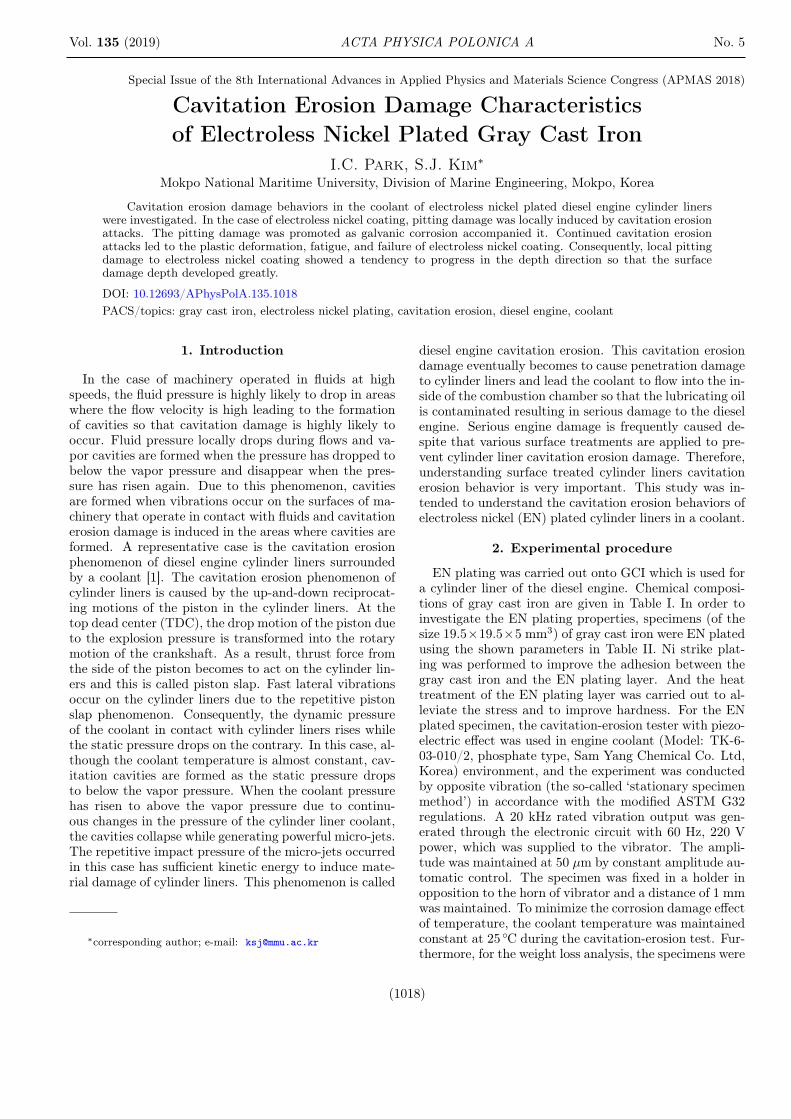
Fig. 2. Surface morphologies of EN plated specimenwith cavitation erosion time: (a) as-received, (b) 30 min,(c) 60 min, (d) 120 min, (e) 180 min, (f) 240 min.
Figure 2 demonstrates the observation of the surfaceshapes of the EN plated specimens with cavitation ero-sion time in a coolant. Up to 60 min of the cavitation ero-sion time, no visually identifiable damage was observedon the surface. As surface damage, pits began to occur inthe central part of the specimen when cavitation erosiontime of 120 min had passed and the number of pits grad-ually increased with cavitation erosion time. These pitsshowed a pattern to gradually progress outward from thecentral part of the specimen with cavitation erosion time.
1020 I.C. Park, S.J. Kim
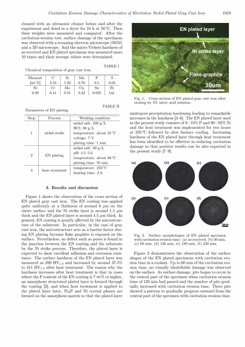
Fig. 3. Weight loss and cavitation rate of EN platedspecimens with cavitation erosion time.
Therefore, the highest density of the pits occurred wasobserved in the central part of the specimen. Accord-ing to the results of studies by Diodati et al. [10] andWon et al. [11], it can be seen that the reason why thecavitation damage is concentrated on the central part ofthe specimen is that the cavity cluster has a spray shapein the form of a trumpet-shaped column from the hornsurface and shows a tendency to have the flow velocityand cavitation damage increasing toward the central part
of the horn. In addition, the foregoing results are con-sistent with the results of a study conducted by Hansonand Morch indicating that the hemispheric cavity clustersformed on the horn surface intensively fail leading to theprogress of surface damage [12].
Figure 3 is a graph that presents weight loss and cav-itation rate of EN plated specimens with cavitation ero-sion time. Since almost no weight loss appears up to120 min of cavitation erosion time, the 120 min sec-tion is judged to be the incubation period presentedby Thiruvengadam [13]. In the case of cavitation dam-age, the shock waves and micro jets occurring when cav-ities collapse repeatedly hit the material surface lead-ing to fatigue, failure, and material losses. In this case,the period before the fatigue effect due to the accumu-lation of cavitation shocks is called incubation period.Therefore, longer incubation periods means more excel-lent cavitation resistance. When cavitation erosion timeof 120 min had passed, an acceleration period appearedin which the weight loss increased almost proportionallywith cavitation erosion time. The cavitation damage ratewas shown to be almost constant with cavitation ero-sion time and in the case of cavitation erosion time of240 min with the highest damage rate, the cavitationdamage rate was measured to be very low as 0.2 mg/hourindicating that the cavitation resistance of EN coatingis excellent.
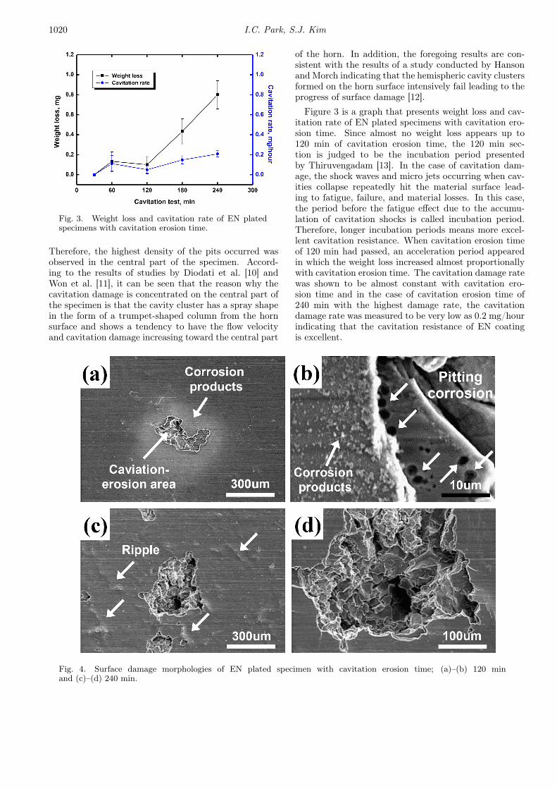
Fig. 4. Surface damage morphologies of EN plated specimen with cavitation erosion time; (a)–(b) 120 minand (c)–(d) 240 min.
Cavitation Erosion Damage Characteristics of Electroless Nickel Plated Gray Cast Iron 1021
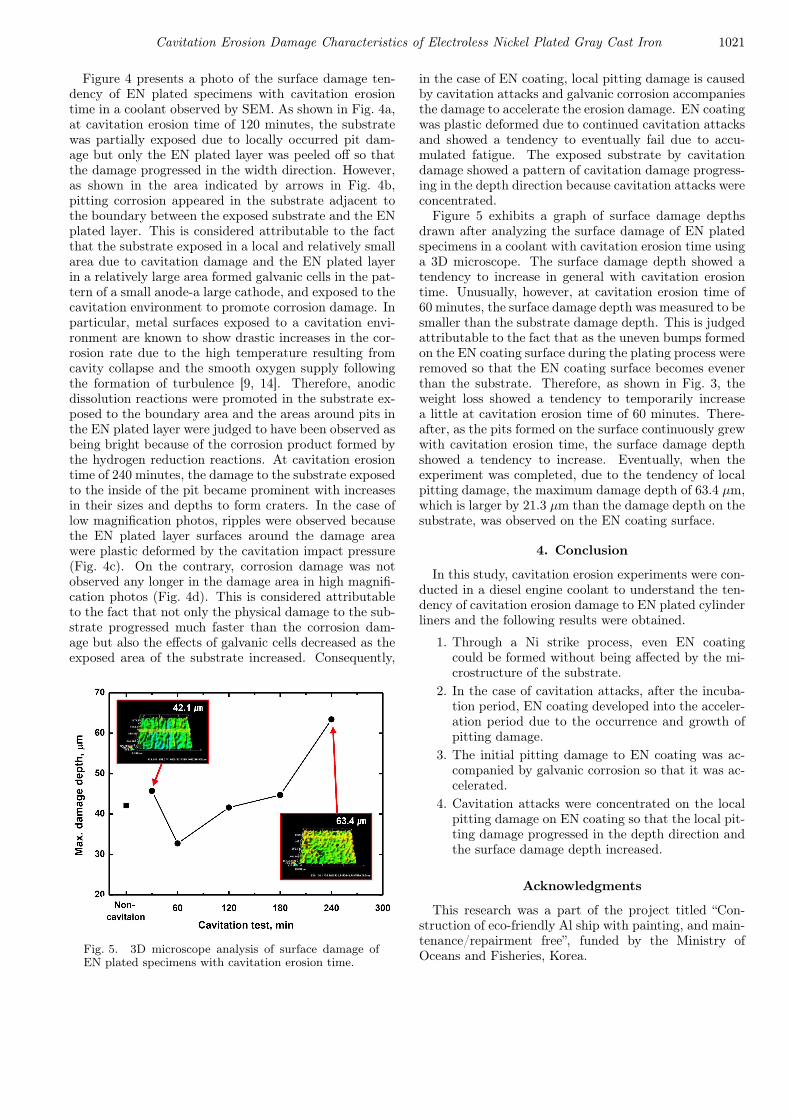
Figure 4 presents a photo of the surface damage ten-dency of EN plated specimens with cavitation erosiontime in a coolant observed by SEM. As shown in Fig. 4a,at cavitation erosion time of 120 minutes, the substratewas partially exposed due to locally occurred pit dam-age but only the EN plated layer was peeled off so thatthe damage progressed in the width direction. However,as shown in the area indicated by arrows in Fig. 4b,pitting corrosion appeared in the substrate adjacent tothe boundary between the exposed substrate and the ENplated layer. This is considered attributable to the factthat the substrate exposed in a local and relatively smallarea due to cavitation damage and the EN plated layerin a relatively large area formed galvanic cells in the pat-tern of a small anode-a large cathode, and exposed to thecavitation environment to promote corrosion damage. Inparticular, metal surfaces exposed to a cavitation envi-ronment are known to show drastic increases in the cor-rosion rate due to the high temperature resulting fromcavity collapse and the smooth oxygen supply followingthe formation of turbulence [9, 14]. Therefore, anodicdissolution reactions were promoted in the substrate ex-posed to the boundary area and the areas around pits inthe EN plated layer were judged to have been observed asbeing bright because of the corrosion product formed bythe hydrogen reduction reactions. At cavitation erosiontime of 240 minutes, the damage to the substrate exposedto the inside of the pit became prominent with increasesin their sizes and depths to form craters. In the case oflow magnification photos, ripples were observed becausethe EN plated layer surfaces around the damage areawere plastic deformed by the cavitation impact pressure(Fig. 4c). On the contrary, corrosion damage was notobserved any longer in the damage area in high magnifi-cation photos (Fig. 4d). This is considered attributableto the fact that not only the physical damage to the sub-strate progressed much faster than the corrosion dam-age but also the effects of galvanic cells decreased as theexposed area of the substrate increased. Consequently,
Fig. 5. 3D microscope analysis of surface damage ofEN plated specimens with cavitation erosion time.
in the case of EN coating, local pitting damage is causedby cavitation attacks and galvanic corrosion accompaniesthe damage to accelerate the erosion damage. EN coatingwas plastic deformed due to continued cavitation attacksand showed a tendency to eventually fail due to accu-mulated fatigue. The exposed substrate by cavitationdamage showed a pattern of cavitation damage progress-ing in the depth direction because cavitation attacks wereconcentrated.
Figure 5 exhibits a graph of surface damage depthsdrawn after analyzing the surface damage of EN platedspecimens in a coolant with cavitation erosion time usinga 3D microscope. The surface damage depth showed atendency to increase in general with cavitation erosiontime. Unusually, however, at cavitation erosion time of60 minutes, the surface damage depth was measured to besmaller than the substrate damage depth. This is judgedattributable to the fact that as the uneven bumps formedon the EN coating surface during the plating process wereremoved so that the EN coating surface becomes evenerthan the substrate. Therefore, as shown in Fig. 3, theweight loss showed a tendency to temporarily increasea little at cavitation erosion time of 60 minutes. There-after, as the pits formed on the surface continuously grewwith cavitation erosion time, the surface damage depthshowed a tendency to increase. Eventually, when theexperiment was completed, due to the tendency of localpitting damage, the maximum damage depth of 63.4 µm,which is larger by 21.3 µm than the damage depth on thesubstrate, was observed on the EN coating surface.
4. Conclusion
In this study, cavitation erosion experiments were con-ducted in a diesel engine coolant to understand the ten-dency of cavitation erosion damage to EN plated cylinderliners and the following results were obtained.
1. Through a Ni strike process, even EN coatingcould be formed without being affected by the mi-crostructure of the substrate.
2. In the case of cavitation attacks, after the incuba-tion period, EN coating developed into the acceler-ation period due to the occurrence and growth ofpitting damage.
3. The initial pitting damage to EN coating was ac-companied by galvanic corrosion so that it was ac-celerated.
4. Cavitation attacks were concentrated on the localpitting damage on EN coating so that the local pit-ting damage progressed in the depth direction andthe surface damage depth increased.
Acknowledgments
This research was a part of the project titled “Con-struction of eco-friendly Al ship with painting, and main-tenance/repairment free”, funded by the Ministry ofOceans and Fisheries, Korea.

1022 I.C. Park, S.J. Kim
References
[1] H.K. Junker, Pistons and Engine Testing, 1st ed.,Springer Science & Business Media Verlag, Berlin2012.
[2] T. Yamasaki, H. Izumi, H. Sunada, Scr. Metall. 15,177 (1981).
[3] S.H. Park, D.N. Lee, J. Mater. Sci. 23, 1643 (1988).[4] P.S. Kumar, P.K. Nair, J. Mater. Process. Technol.
56, 511 (1996).[5] I. Apachitei, J. Duszczyk, L. Katgerman,
P.J.B. Overkamp, Scr. Metall. 38, 1347 (1998).[6] W. Reidel, Electroless Nickel Plating, 2nd ed., Cam-
bridge Scientific Abstracts, Cambridge 1911.[7] C.J. Lin, J.L. He, Wear 259, 154 (2005).
[8] C.J. Lin, K.C. Chen, J.L. He, Wear 261, 1390 (2006).[9] W.J. Tomlinson, M. Girardi, Surf. Coat. Tech. 31,
213 (1987).[10] P. Diodati, G. Giannini, Ultrason. Sonochem. 8, 49
(2001).[11] D.S. Won, K.S. Jeon, Y.T. Kho, J.H. Lee, Corros.
Sci. Technol. 23, 215 (1994)[12] I. Hansson, K.A. Mørch, J. Appl. Phys. 51, 4651
(1980).[13] A. Thiruvengadam, H.S. Preiser, J. Ship Res. 8, 39
(1964)[14] J. González-García, V. Sáez, I. Tudela, M.I. Díez-
Garcia, M. Deseada Esclapez, O. Louisnard, Water2, 28 (2010).


![Experimental Research on Cavitation Erosion Detection Based on … · 2012-10-09 · estimate cavitation erosion by observing the removal of the paint [3]. They detect cavitation](https://img.pdfslide.us/doc/110x75/5e93bba127dcb37304714469/experimental-research-on-cavitation-erosion-detection-based-on-2012-10-09-estimate.jpg)