Embed Size (px)
Citation preview

IEEE Transactions on Dielectrics and Electrical Insulation Vol. 11, No. 6; December 2004 1037
Causes and Potential Remedies of Brittle Fracture Failurež /of Composite Non-Ceramic Insulators
M. Kumosa, L. Kumosa and D. ArmentroutCenter for Advanced Materials and Structures
Department of Engineering, University of Denver2390 S. York St., Denver, Colorado 80208, USA
ABSTRACTExisting brittle fracture models have been reviewed and their applicability to ex-
( )plain the in-service brittle fracture failure of composite non-ceramic insulators isevaluated. It is shown that the only brittle fracture model that can explain all as-pects of the brittle fracture process is a model based on the formation of nitric acidsolutions in-service. The chemical cause of brittle fracture is identified in this workand recommendations are made on how to avoid brittle fracture in-service by properselection of composite insulator rods resistant to brittle fracture. An attempt ismade to clarify misconceptions that exist in the literature regarding the causes ofbrittle fracture and the most suitable prevention methods.
Index Terms — Non-ceramic insulators, composite insulators, polymer insula-( )tors, brittle fracture, stress corrosion cracking, glass reinforced polymer GRP
composites, fracture prevention.
INTRODUCTIONŽ .OMPOSITE non-ceramic insulators, sometimesCalso called ‘‘polymer’’ or ‘‘polymeric’’ insulators, can
occasionally fail in service in a catastrophic manner byw xbrittle fracture 1�22 . Brittle fracture is a failure process
Ž .called stress corrosion cracking SCC which, in someŽ .cases, can occur in the glass polymer reinforced GRP
rods which are used as the principal load bearing compo-nents of the insulators. SCC can occur in unidirectionalE-glassrpolymer composites when exposed to an acidicenvironment and mechanical tensile stresses. To preventbrittle fracture the insulators must be protected againstwater ingress into their energized end fittings. This factseems to be widely accepted by the insulator communityw x1 . However, the presence of water inside insulators and,in particular, on the surface or inside the glass reinforced
Ž .polymer GRP rods can have different effects on thestructural integrity of the rods. The presence of water in-side composite insulators will not always lead to brittle
w xfracture 5, 11 . If corroded, however, the GRP rods, willmechanically fail by brittle fracture leading to catas-trophic, unpredictable mechanical failures of insulatorsŽ w x.Figures 1a and 1b, 9, 11 .
In order to avoid brittle fracture failures, composite in-sulators should be protected against water ingress intotheir energized end fittings, which is very difficult if not
Manuscript recei®ed on 7 May 2003, in final form 5 January 2004.
impossible to accomplish for long periods of time, consid-ering the very harsh in-service conditions. The easier wayof preventing brittle fracture is by proper design of theGRP rods making them entirely immune to SCC and thusbrittle fracture. However, in order to do that, the actualcauses of brittle fracture must be well understood. In par-ticular, the chemical environment responsible for SCC in
Ž .composite high voltage HV insulators must be clearlyidentified. Then, remedies can be recommended to theinsulator manufacturers and users on how to prevent insu-lator failures by brittle fracture. In this work, the mostimportant models of brittle fracture are evaluated, the ap-propriate one is then selected and recommendations aregiven on how to prevent brittle fracture in-service by de-signing a composite rod resistant to this type of mechani-calrchemical failure.
2 CAUSES OF BRITTLE FRACTUREOF COMPOSITE INSULATORS
2.1 EXISTING MODELS OF BRITTLEFRACTURE
It appears that there are three currently competingmodels of the brittle fracture processes. They are brieflydescribed below and later on thoroughly evaluated in Sec-tions 2.3.1�2.3.3 of this work.
w xModel I. According to 2 ‘‘the failure of in-service NCIsin the brittle fracture mode can occur under the influence
1070-9878rrrrr04rrrrr$20.00 � 2004 IEEE 1037

( )Kumosa et al.: Causes and Potential Remedies of Brittle Fracture Failure of Composite Non-Ceramic Insulators1038
Figure 1. Typical examples of brittle fracture failures of 500 kVŽ .composite non-ceramic insulators. a, failure inside the fitting; b,
w xfailure above the hardware 9,11 .
of water and mechanical stresses, and the failure is morelikely to happen with water than with acids’’.
w xModel II. According to 3, 4 , ‘‘the brittle fracture ofw xthe FRP Fiber Reinforced Polymer rod of composite in-
sulators is associated with an acid, derived from the hard-ener, lodged on the surface of the rod combined with theingress of water at the same location and a mechanicaltension load applied to the insulator.’’
Model III. The brittle fracture process is caused by ni-tric acid being formed in service due to corona discharges,
w xozone and moisture 5�16 .
The only agreement between Models I � III is that theprocess is initiated by the water ingress into a compositeinsulator. Therefore, in order to prevent brittle fracture,composite non-ceramic insulators should be protectedagainst moisture ingress. This seems to have been widely
w xaccepted 1 . In the past, other models have been pro-posed assuming, for example, that brittle fracture couldbe caused by oxalic acid generated in-service from poly-
w xmer matrix decomposition due to corona discharge 17 .However, no evidence of oxalic acid presence in any
w xfield-failed insulator has ever been found 6, 8 . Specula-tions were also made in the past that brittle fracture could
Ž .be caused by mechanical fatigue aeolian vibrations . Thisw xissue was also investigated 18, 19 . No evidence that typi-
cal aeolian vibrations could initiate brittle fracture in GRProds in the absence of an acidic corrosive environmentwas found. It was also shown that typical aeolian vibra-tions could not accelerate the brittle fracture process in aunidirectional glassrpolymer composite with the lowestresistance to brittle fracture. It should be stated howeverthat no systematic research has ever been done on theeffect of aeolian vibrations on the initiation of brittle frac-ture. Considering the possible number of initiation sites ofbrittle fracture in a typical non-ceramic insulator this is-sue is not straightforward to investigate. If it exists, theeffect of aeolian vibrations on the initiation of brittle frac-ture could depend not only on the type of acid and thechemistry of the GRP rod but also very strongly on thefitting design.
2.2 CREDIBLE BRITTLE FRACTUREMODEL
A credible brittle fracture model should explain thefailure process and, in particular, should satisfy seven factsand two requirements identified so far by the authors andothers on the basis of observations.
2.2.1 FACTS
1. Brittle fracture is a stress corrosion process occur-ring in pultruded E-glassrpolymer rods used as load bear-
w xing components in non-ceramic insulators 1�16 .
2. The majority of brittle fracture failures have oc-curred just outside the energized end fitting with only a
w xfew failures occurring inside the fitting 1, 3, 5, 6, 8�11 .
3. There are significant differences in the morphologiesof the brittle fracture surfaces formed inside and outside
w xthe end fitting 6, 8, 9, 10 .
4. There is a very strong relationship between the loca-Ž .tion of failure inside the fitting, outside, mixed and the
w xpresence and location of the grading rings 10 . If gradingrings are present the failure always occurs just above the
w xgrading ring 10 .
5. Not a single brittle fracture failure of composite sus-pension insulators has ever been documented to occur ei-
1070-9878rrrrr04rrrrr$20.00 � 2004 IEEE1038
IEEE Transactions on Dielectrics and Electrical Insulation Vol. 11, No. 6; December 2004 1039
ther near the grounded end or far away from the fittingsw x1 .
6. No brittle fracture failures have been reported to oc-cur as a combined effect of stress corrosion and mechani-
w xcal damage to a GRP rod caused by gunshots 1 . Mechan-ical damage to the rubber housing and the exposure ofthe GRP rod to water do not immediately lead to brittlefracture.
7. The probability of brittle fracture failure increasesw xwith voltage. According to 1 , ‘higher transmission line
voltages are associated with higher number of brittle frac-Ž .ture failures .’’
2.2.2 REQUIREMENTS
1. It should be possible to identify a corrosive environ-ment directly in the brittle fracture zones in failed com-posite insulators by brittle fracture and the identificationprocess of the environment responsible for failure should
w xbe unambiguous, unique and reproducible 12, 22 .
2. It should be possible to simulate the brittle fractureŽ .process inside and outside the fitting under laboratory
conditions and show that the initiation rates of SCC invarious E-glassrpolymer composites are in agreement with
wthe rates of brittle fracture failures in-service 6, 8, 10, 14,x16, 18, 21 .
2.3 EVALUATION OF BRITTLE FRACTUREMODELS I-III
An evaluation of Models I-III is performed and argu-ments are made discussing whether the models satisfy allthe requirements and facts listed above.
2.3.1 WATER AS CAUSE OF BRITTLEFRACTURE WITHOUT ELECTRIC FIELDS
( )MODEL I
w xIt was postulated in 2 , based on experimental evi-dence, that water was more damaging to the GRP rodsthan acids and that brittle fracture was more likely to hap-pen in water than in acids. It was also claimed that brittlefracture was generated in various E-glassrpolymer rodsw x20 by subjecting them to four point bending in the pres-ence of ultra clean water.
w xThe model proposed in 2 cannot be accepted:
� w xThis model could not be independently verified 21 .The brittle fracture process could not be generated in the
w xsame composites, from the same supplier 20 by subject-ing them to four point bending and the same type of highpurity water.
� This Model cannot explain all the facts and satisfythe requirements listed in section 2.2 with the exception
w xof fact �1, and even this is questionable 21 . Model Idoes not explain facts �2�7. In service, composite insula-
w xtors can be severely damaged by gunshots 23 with their
GRP rods exposed to moisture ingress. Therefore, if thew xmain conclusion of 2 is true, why have composite insula-
tors damaged by gun shots not been failing by brittle frac-Ž .ture in-service fact �6 ?
Other arguments against this model have been pre-w xsented in 21 .
2.3.2. EVALUATION OF MODEL II
wModel II has been receiving some attention recently 3,x4 . All aspects related to the applicability of this model to
explain the brittle fracture failures of composite insulatorsshould be evaluated. An attempt is made in this work toanswer two questions:
w x1. Is the mechanism suggested in 3, 4 possible in E-glassrpolymer composite materials based on polyester,epoxy or vinyl ester resins?
2. Does this model explain all the facts and observa-tions listed in section 2.2 ?
w xConcerning 1 if the mechanism proposed in 3, 4 can-not occur in E-glassrpolymer composites commonly usedin non-ceramic insulators, any further discussion on theapplicability of the model to explain insulator failureswould be unnecessary. Several industrial sources haveprovided responses to question �1:
� w xAccording to 24 , ‘‘the chemical reactions describedw xin 4 can happen in an epoxyranhydride system but can-
not occur in a polyester or vinyl esterrperoxide reaction.There is no anhydride present in either polyester or vinylester resins. The reaction that occurs between these tworesins and traditional pultrusion peroxides is an acid reac-
w xtion’’. Pepper 24 further stated that ‘‘Anhydrides reactwith moisture quickly and exothermically. They are usedto cure epoxies in a ‘A q B ™ ABABABAB....’ se-quence. It seems likely there will be residual amounts leftin a pultruded matrix, and these residual amounts will re-
Ž .act with moisture, generating problems diacid . Vinyl es-ters and polyesters have no components that react with
Žmoisture exothermically or quickly with the exception of.ortho resins . They cure free radically, using a peroxide in
an ‘A q B ™ ABBBBBBBBBB...’sequence.’’
� w xAccording to 25 , ‘‘In general a high level of acid willaffect the performance of the finished resin. In order tominimize problems associated with the presence of acidthe standard specification for anhydrides is 2% maximumof the corresponding acid. While there is no truly quanti-tative data it is generally assumed that acid concentrationsabove 3% will have a negative impact on the finishedproduct with regard to Tg, electrical properties and physi-cal strength of the final product. In order to ensure thatproblems with acid are not encountered, anhydride manu-facturers take great pains to keep moisture away from theirproduct. Typical production material has an acid contentbelow 1%, comfortably in the safe range for product per-formance. We encourage our consumers to store material
1070-9878rrrrr04rrrrr$20.00 � 2004 IEEE 1039

( )Kumosa et al.: Causes and Potential Remedies of Brittle Fracture Failure of Composite Non-Ceramic Insulators1040
under nitrogen or install a desiccant to ensure moisture istaken out of the air prior to its contact with the anhydride’’.
� w xAccording to 26 , ‘‘the presence of free acids asresidue after curing in epoxy resins is a high possibilityhowever it is highly unlikely that such acids can be gener-ated in vinyl ester and polyester resins’’.
� w xAccording to McQuarrie 27 , ‘‘this particular mecha-Ž w x.nism as stated by Tourreil et al. 4 definitely could oc-
cur, but only with epoxyranhydride resin systems. With theproper selection of the anhydride and manufacturing con-ditions, this condition can be eliminated. This mechanismcannot happen with a vinyl ester or polyester rods sincethere is no hardener in these composite systems’’.
w xIn summary, the chemical reactions suggested in 3, 4can happen, but only in poorly manufactured E-glassrepoxy GRP rods. They cannot occur in GRP rodsbased on vinyl ester and polyester resins. It should bementioned that a vast majority of brittle fracture failuresoccurred in composite insulators with E-glassrpolyester
w xrods 5, 6, 8, 10 . Approximately 90% of field failed unitssubmitted to our laboratory for analysis were based oneither E-glassrpolyester or E-glassrmodified polyester.
w xThe 500 kV failures on the West Coast 9 occurred ininsulators with E-glassrmodified vinyl ester rods. The au-
Žthors of this paper know of very few failures two, perhaps.three of insulators based on E-glassrepoxy rods over the
last ten years. During the same time, they have examinedapproximately 30 failures of insulators with the polyesterbased rods and three with the modified vinyl ester basedrods.
wClearly, the mechanism proposed by Tourreil et al. 3,x4 is in agreement with Fact �1 that the failure of the
rods is caused by SCC since the process was reproducedunder laboratory conditions using acids derived from the
w xmanufacturing process of the rods 3 . Transverse frac-ture surfaces were generated in GRP rods under labora-
w xtory conditions indicating SCC 3 . However, the otherŽ .facts �2-�7 cannot be explained using this model. The
model cannot explain why a majority of brittle fracturefailures occurred outside the fitting with only very few
Ž .failures occurring inside the fitting Fact �2 . This factcan only be explained using Model II if the failure outsidethe fitting is in each case caused by the breach of therubber housing outside the fitting, which does not agree
w xwith our field experience 1 . Also, Model II does not ad-dress the difference in the failure morphologies inside and
Ž .outside the fitting Fact �3 . According to Model II, themorphologies of the brittle fracture surfaces formed in-
w xside and outside the fittings 5, 6, 8�11 should be thesame. Moreover, the model does not explain why all brit-tle fracture failures outside the fittings occurred just above
Ž .the grading rings, if present Fact �4 .
Facts �5 and �6 also cannot be explained using thew xmodel proposed by Tourreil et al. 3, 4 . According to
Model II, gunshot damage to composite insulators shouldcause brittle fracture since in each case the rubber hous-ing would be destroyed allowing free access of water tothe GRP rods. Similar to Model I, according to Model IIany contact between water and GRP rods, at any locationalong the rods, should cause brittle fracture. This does
w xnot agree with the field experience 1 .w xIn 4 the authors’ identified the chemical environment
in an in-service failed composite insulator by brittle frac-ture. However, the identification of the environment didnot satisfy the second part of requirement �1. Insignifi-cant differences were presented in the IR spectra taken
Ž .from areas affected by brittle fracture curves a and bŽ .and from the unaffected bulk curve c of the rod as shown
w x w xin Figures 4.2 and 4.3 of 4 . The statement made in 4that ‘‘The small increase for curves ‘‘a’’ and ‘‘b’’ at 1702cmy1 is associated with the acid formed from the hard-ener’’ proves that the identification was rather uncertain,especially if compared with the identification procedures
w xdeveloped and presented in 12, 22 .
2.3.3 EVALUATION OF MODEL III
According to Model III nitric acid can be formed exter-nally, on the insulator surface close to the energized end
w xfitting, due to water droplet coronas 28 or internally dueto partial discharges inside cracks and large voids occa-
w xsionally filled with absorbed water 5-11, 19, 29 . The factthat nitric acid can be formed when water is exposed tocorona discharges has been known since 1784 when dis-
w xcovered by Cavendish. More recently, Kuhl 15 showedthat when distilled water was subjected to an ac discharge,the pH value of the water after the discharge was 2.9. Healso stated ‘‘more evidence for the presence of nitric acidand nitric acid oxides and their derivatives were found onthe surfaces of polluted insulators from experiments andtests. 110 kV silicone composite insulators showed 4�5%
w xnitrogen pollution after 5 years of service’’ 15 . In anotherpublication, either positive or negative coronas over dis-tilled water resulted in a pH of about 3 in the case of the
w xnegative corona and about 4 for the positive corona 30 .It was also stated that the nitric acid concentration mea-sured during the corona experiments over water de-
w xpended quite strongly on the air pollution 30 .
If relatively strong nitric acid solutions form on the en-ergized end fitting and housing, and if an insulator is notprotected against water ingress, these acidic solutions af-ter penetrating the fitting will reach at some point a GRP
wrod causing SCC and brittle fracture inside the fitting 6,x8, 9, 10, 11 . The critical acid concentration for brittle
fracture under this scenario does not have to be very high.For E-glassrpolyester type GRP rods, the critical pH of
w xnitric acid has to be around 3 to 3.5 6, 8 . This acid con-centration can be easily generated under ac discharge over
w xdistilled water 15, 30 . Most likely ac discharges over ei-ther rain or tap water would cause the pH value of nitric
1070-9878rrrrr04rrrrr$20.00 � 2004 IEEE1040

IEEE Transactions on Dielectrics and Electrical Insulation Vol. 11, No. 6; December 2004 1041
acid to be even lower, since NOx would already be pre-sent inside these types of water making the nitric acid for-mation process even easier. In addition, the acid concen-tration would be increasing with evaporation.
Ž .For other polymer resins epoxies and vinyl esters theŽ .critical acid concentration must be higher lower pH . It
has been shown that in order to propagate stress corro-sion cracks in an E-glassrepoxy composite the critical ni-
w xtric acid concentration must be between pH 2 and 3 6, 8 .There are important reasons why acid concentrations mustbe higher in the case of the epoxy and vinyl ester typecomposites in comparison with the critical acid concentra-tion of the E-glassrpolyester composites. This will be dis-cussed further in Section IV of this work.
If the acid concentration is not high enough, a weakŽnitric acid solution most likely contaminated with all sorts.of other compounds after penetrating an insulator at the
Ž .fitting if not protected against moisture ingress in con-tact with the GRP rod will not be able to cause SCC and
Ž .thus brittle fracture. However, water or weak acids caneasily propagate upwards outside the fitting into the fieldw x5, 6, 8, 9, 11, 16 . This propagation process of weak acidswill be especially easy along the GRP rodrhousing inter-
wfaces due to capillary action and the electric field 5, 6, 8,x9, 11, 16, 22 . In addition, water always damages the GRP
Ž .rods without SCC forming all types of micro- andw xmacro-cracking 2 allowing more water to be absorbed by
the composite. The effect of either water or weak nitricacid on the composites will very strongly depend on the
w xcomposite type 35�41 .
The presence of water in the E-glassrpolymer pul-truded rods will generate internal cracking along thefiberrmatrix interfaces and thus allow much faster watertransport along the rod from inside the fitting into the
Žhigh voltage area above the fitting if grading rings are not. Žpresent and above the grading ring if the rings are pre-
.sent . Then, partial discharges can develop inside thecracks and voids generated by water, especially if they areoccasionally filled with contaminated water depending onthe moisturerrain conditions in the atmosphere outside
w xthe insulator 6, 16, 29 . This has been numerically shownby modeling various cracks and large voids inside a GRProd and at the rodrhousing interface near the energized
w xend fittings 6, 16, 29 . The presence of internal cracks inŽthe rods filled with water penetrating the interface, evap-
.orating and re-penetrating again and partial dischargeswill allow sufficiently strong nitric acid solutions to be
Ž .formed internally inside composite insulators in-service.This will lead to the brittle fracture of a composite insula-
Žtor just outside the fitting or above its grading ring if pre-. w xsent 5, 6�11 .
The mechanism of nitric acid formation process at thehousingrGRP rod interface has just been experimentally
w xverified 22 . A field failed composite suspension insulatorŽ .voltage unknown with an E-glassrpolyester rod was in-
w xFigure 2. FTIR analysis of a field failed non-ceramic insulator 22 .a, failure morphology with eight sites selected for FTIR; b, FTIR
Žspectra from 8 sites shown in Figure 2a; c, FTIR spectra expanded.regions .
Ž .vestigated by FTIR Spectroscopy Figure 2 . A large sepa-ration was found at the interface between the rod and
Ž .housing Figure 2a . Eight sites were selected for the FTIRanalysis within and around the brittle fracture zone. Nodetectable nitrate band was found in site 1 indicating thatthere was no nitric acid present on the housing. The largestconcentration of nitric acid, nitrate bands at 1386.8 cmy1,was found on both sides of the rodrhousing separation
1070-9878rrrrr04rrrrr$20.00 � 2004 IEEE 1041

( )Kumosa et al.: Causes and Potential Remedies of Brittle Fracture Failure of Composite Non-Ceramic Insulators1042
Ž .sites 3 and 4 , indicating that the main source of nitricacid production occurred inside the rubberrrod separa-tion. As the brittle fracture crack propagated from its ini-
Ž . Ž .tiation site site 4 towards the center of the rod sites 5-8Žthe acid concentration decreased see the nitrate bands at
.1386.8 cm-1 for sites 5-8 . The acid was generated at theinterface between the GRP rod and the rubber housing
waccording to the model proposed by Kumosa et al. 5, 6, 8,x9, 10, 11, 16 . Most importantly, the FTIR analysis pre-
w xsented in 22 pinpointed for the first time the actual ni-tric acid generation spot for the type of failure associatedwith the formation of main brittle fracture cracks away
w xfrom the fitting. The data presented in Figure 2 22 is thefirst proof that nitric acid can be formed at the rodrhous-ing interface, explaining brittle fracture away from the en-ergized end.
The model based on the nitric acid formation processŽ .in-service Model III has been built based on research
w x5-12, 14, 16, 18, 19, 21, 22, 29, 31�41 . In particular, thedetailed analysis of the field failed units at two large US
w xutilities 5, 6, 8�10, 16 helped to create a failure modelthat is in agreement with all the facts listed in Section 2.2.The model clearly explains why brittle fracture failures
can occur either inside or just outside of the energizedŽ .end fittings Fact �2 . Using this model it can also be
explained why significant differences exist between thefracture surface morphologies outside and inside the fit-
Ž .tings Fact �3 . The model can also be used to explainwhy in the presence of grading rings the failure outsidethe fitting will always occur above the rings, and never
Ž .between the fittings and the rings Fact �4 .
Since the presence of high fields is essential in the brit-tle fracture process according to Model III, this modelcan also be used to explain why brittle fracture failures ofsuspension insulators have never been documented to oc-
Ž .cur far away from the energized end fittings Fact �5 .The model also explains why not a single brittle fracturefailure of composite insulators has been reported due to
Ž .gunshot damage Fact �6 . This type of failure can occurhowever only if an insulator is damaged and its GRP rodexposed in a close proximity of the energized end fitting.The model can also be used to explain why higher trans-mission line voltages are associated with higher numbers
w xof brittle fracture failures, as reported in 1 .
Most importantly, the model based on the nitric acidŽ .formation process in-service Model III has been experi-
mentally verified by:
� Identifying nitrate on the composite surfaces insidesuspension composite insulators which failed in-service bybrittle fracture, and the identification process was unam-
w x Ž .biguous and repeatable 12, 22 Requirement �1 .
� Simulating the process under laboratory conditionsw x w xwith 6�8, 21 and without 6-8, 10, 14, 16, 18, 19, 32�38
Ž .corona discharges Requirement �2 .
2.4 SELECTION OF MOSTAPPROPRIATE BRITTLE FRACTURE
MODEL.Brittle fracture is not a simple failure mechanism. This
process is caused by the combined action of electrical andmechanical stresses in the presence of a chemical environ-
Ž . w xment moisture, ozone, pollution, etc. 5�16 . Due to theŽpresence of the three environments mechanical, electri-
.cal and chemical complex fracture processes occur in acomposite insulator in service, which we are beginning tounderstand. The brittle fracture model based on the for-
Ž .mation of nitric acid Model III is the only model thatexplains the relationship between the presence and loca-tion of the grading rings, electric field concentration and
Žthe location of brittle fracture failure either inside or.outside the energized end fittings . The other two models
Ž .Models I and II do not consider the presence of electricfields and their effect on the brittle fracture process.
If brittle fracture was caused either by clean, non-acidicw xwater as is stipulated in 2 or by an acid derived from thew xhardener according to 3, 4 , brittle fracture failures of
composite insulators should have been able to occur atany location along the rod where the rubber housing was
Ž .breached for example by gunshots . Obviously, such fail-ures have not yet been observed and reported. There hasalways been a very strong correlation between the failurelocation and the electric field concentration with the fail-ures occurring always near the energized end fittings. Thiswas stated by Tourreil et al. ‘‘most fractures were close to
w xthe HV end fitting’’ 3 . This means that without the field,the failure process cannot occur unless the location offailure outside the fitting is always explained in terms of
Ž .the rubber erosion corona cuttings caused by high volt-age, and this would be contradictory to our field experi-
w xence 1 .
3 PREVENTION OF BRITTLEFRACTURE
Brittle fracture of composite insulators can be pre-vented either by protecting the GRP rods from any con-tact with moisture in the presence of high voltage fields orby the design of a GRP rod which will be fully resistant to
w xSCC and thus brittle fracture 1 . Obviously, if we coulddesign a GRP rod with almost perfect resistance to SCCthen we would not have to worry about how to protect thecomposite insulators against moisture ingress, at least in
wtheory. Major efforts have been undertaken 5�8, 14, 16,x18, 19, 21,31�41 over the last several years to design such
a GRP rod. It was assumed that the insulator core GRProd must be resistant predominantly to stress corrosioncracking in nitric acid since this is the most likely chemical
wenvironment responsible for brittle fracture failures 6�16,x22 . Since the brittle fracture process above the grading
1070-9878rrrrr04rrrrr$20.00 � 2004 IEEE1042

IEEE Transactions on Dielectrics and Electrical Insulation Vol. 11, No. 6; December 2004 1043
w xring, caused by moisture and ac discharges 6, 8, 10, 21 ,wcould not be controlled under laboratory conditions 18,
x21 it was also assumed that if the GRP rod is resistant toSCC in nitric acid, such a rod would also be resistant tomoisture and corona discharges.
In the design process of a GRP rod entirely immune toSCC, it was also assumed that the electrical properties ofthe rod should not be compromised in comparison with
w xthe rods currently being used in-service 19, 41 . In Sec-tion 4, a brief description of the GRP rod design, omitted
w xin 1 , are presented.
4 GRP ROD RESISTANT TO SCC ANDBRITTLE FRACTURE
4.1 COMPOSITE MATERIALS TESTED ATOGI AND DU FOR THEIR RESISTANCE
TO SCCUnidirectional E-glass and ECR-glassrpolymer matrix
composites were tested for their resistance to SCC in ni-tric acid. Two types of ECR fibers with high and low seedcounts were analyzed. Polyester, modified polyester,epoxy, vinyl ester and modified vinyl ester with and with-out fillers were considered. The composite systems testedso far have been provided by one supplier. Other systems,mostly based on the E-glass fibers with epoxy from twoother insulator manufacturers were also investigated in aless systematic manner.
During brittle fracture three stages of SCC have beenŽ . w xidentified Figure 3 34�36 . In Stage I, single fiber cracks
are formed on the surface of the GRP rods. Then, in StageII, the process expands towards the adjacent glass fibers.In Stage III one large stress corrosion crack, establishedduring Stages I and II propagates across the rod leadingto its failure. Stages I and II are predominantly initiationstages and Stage III is predominantly the propagationstage. Unidirectional glassrpolymer composites used in
Ž .composite non-ceramic insulators can be investigated forŽ .their resistance to the initiation Stages I and II and
Ž .propagation Stage III of SCC under various chemical andmechanical conditions.
4.2 RESISTANCE TO PROPAGATION OFSCC IN NITRIC ACID
Ž .Initially the resistance to SCC propagation only waswinvestigated using the constant K specimen geometry 6-8,I
x16, 18, 21, 32, 33 and GRP rods subjected to axial tensionw x14, 16, 19, 38 . Both the constant K and GRP rods hadI
artificially introduced short pre-cracks. Having the pre-cracks, the location of the fracture process could be con-trolled making the monitoring process by acoustic emis-sion much easier. Moreover, the pre-cracks introduced tothe K and rod specimens concentrated stresses in theI
composite, enhancing the stress corrosion process.
Figure 3. Schematic stages of SCC and SEM micrographs from uni-directional E-glassrpolymer specimens subjected to nitric acid for 72
w xh under four-point bending loads 34-36 . a, Stage I; b, Stage II; c,Stage III.
The most important conclusions from the research per-formed using the K specimen geometry are presented be-I
w xlow 16, 33 .
� The overall result for E-glass fiber based compositeswas that all the tested composites were susceptible to SCC
Ž .in a nitric acid solution pH 1.2 . Moreover, the crackpropagation rates in the composites were very similar con-sidering stable crack growth which indicated the type ofpolymer had an insignificant effect on the stress corrosionfracture process.
� The ECR fiber composites all proved to be equallyresistant to the propagation of stress corrosion cracks innitric acid with no significant difference attributed to thechoice of matrix material or magnitude of the applied load.
Very similar conclusions were obtained from the GRPw xrod testing 14,18,19,38 . The fact that the crack propaga-
tion rates in the composites were very similar was not sur-prising as the crack tip velocity in a glass fiber under stress
Ž .corrosion conditions is very high approximately 200 mrsw x32 . In addition, the volume fraction of fibers in the com-
Ž .posites was high 55% by volume . Thus, the fracture pro-cess in an individual fiber occurs so fast that the surround-
1070-9878rrrrr04rrrrr$20.00 � 2004 IEEE 1043
( )Kumosa et al.: Causes and Potential Remedies of Brittle Fracture Failure of Composite Non-Ceramic Insulators1044
ing matrix fractures immediately after the fiber failure.Therefore, any difference in the fracture toughness prop-erties of the polymer has a minute effect on the macro-scopic crack growth rates in the unidirectional E-glassrpolymer systems under stress corrosion conditions.
The effect of aeolian vibrations on the SCC in nitricw xacid was briefly examined using the GRP rods 14 and
another specimen geometry, flat composite coupons alsow xwith artificially introduced cracks 18, 19, 40 . The main
conclusion from that research was that low amplitude andlow frequency vibrations generate smaller transverse stresscorrosion cracks in the rods than the cracks generated un-
w xder static mechanical loads 14 . However, the crack prop-agation rates appear to be not affected by the aeolian vi-
w xbrations 18, 19, 40 . The effect of vibrations on the proba-bility of composite brittle fracture has not yet been thor-oughly investigated.
4.3 RESISTANCE TO INITIATION OF SCCSince the crack propagation work described above
showed that the propagation rates in the E-glassrpolymercomposites do not depend on the type of polymer, addi-tional efforts were undertaken to evaluate the effect of
Ž .glass fibers E-glass, ECR-high seed and ECR-low seedŽand polymer resins modified polyester, epoxy and vinyl
. w xester on the initiation of SCC 34�38 . The three E-glassrpolymer systems are the most frequently used com-posites in non-ceramic insulators. The effect of surfacesandblasting of the E-glass and ECR-glassrpolymer com-posites on the initiation of SCC in nitric acid was also
w xexamined 19, 36�68 . All the E-glass and ECR-glass com-posites tested in this study came from one supplier.
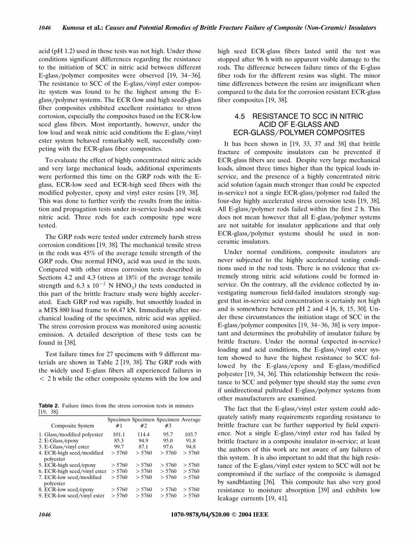
The composites were subjected to four point bendingwusing a four point bend fixture shown in Figure 4 19,
x36�38 . A nitric acid solution with pH 1.2 was used as acorrosive environment. Acoustic emission was monitoredduring testing. Since acoustic emission is directly propor-
Figure 4. Schematic of the four point bend fixture used in the stressw xcorrosion experiments 19, 34-37 .
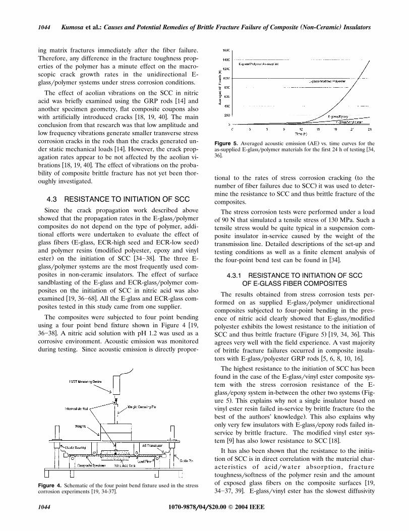
Ž .Figure 5. Averaged acoustic emission AE vs. time curves for thewas-supplied E-glassrpolymer materials for the first 24 h of testing 34,
x36 .
Žtional to the rates of stress corrosion cracking to the.number of fiber failures due to SCC it was used to deter-
mine the resistance to SCC and thus brittle fracture of thecomposites.
The stress corrosion tests were performed under a loadof 90 N that simulated a tensile stress of 130 MPa. Such atensile stress would be quite typical in a suspension com-posite insulator in-service caused by the weight of thetransmission line. Detailed descriptions of the set-up andtesting conditions as well as a finite element analysis of
w xthe four-point bend test can be found in 34 .
4.3.1 RESISTANCE TO INITIATION OF SCCOF E-GLASS FIBER COMPOSITES
The results obtained from stress corrosion tests per-formed on as supplied E-glassrpolymer unidirectionalcomposites subjected to four-point bending in the pres-ence of nitric acid clearly showed that E-glassrmodifiedpolyester exhibits the lowest resistance to the initiation of
Ž . w xSCC and thus brittle fracture Figure 5 19, 34, 36 . Thisagrees very well with the field experience. A vast majorityof brittle fracture failures occurred in composite insula-
w xtors with E-glassrpolyester GRP rods 5, 6, 8, 10, 16 .
The highest resistance to the initiation of SCC has beenfound in the case of the E-glassrvinyl ester composite sys-tem with the stress corrosion resistance of the E-
Žglassrepoxy system in-between the other two systems Fig-.ure 5 . This explains why not a single insulator based on
Žvinyl ester resin failed in-service by brittle fracture to the.best of the authors’ knowledge . This also explains why
only very few insulators with E-glassrepoxy rods failed in-service by brittle fracture. The modified vinyl ester sys-
w x w xtem 9 has also lower resistance to SCC 18 .
It has also been shown that the resistance to the initia-tion of SCC is in direct correlation with the material char-acteristics of acidrw ater absorption , fracturetoughnessrsoftness of the polymer resin and the amount
wof exposed glass fibers on the composite surfaces 19,x34�37, 39 . E-glassrvinyl ester has the slowest diffusivity
1070-9878rrrrr04rrrrr$20.00 � 2004 IEEE1044

IEEE Transactions on Dielectrics and Electrical Insulation Vol. 11, No. 6; December 2004 1045
of water and the lowest moisture content, the least hardŽ .resin highest fracture toughness and the least amount of
exposed fibers on its surface, therefore this composite sys-wtem has the highest resistance to the initiation of SCC 19,
x34�37 . It has also been shown that the effect of sand-blasting on the initiation and propagation of stress corro-sion cracks in low and medium sandblasted composite
w xspecimens is slightly positive 19, 36, 37 . Sandblasting ap-plied to the composites relieved the residual thermalstresses in the fibers on the composite surface, slightly im-proving the resistance of the composites to the initiation
w xof SCC and thus brittle fracture 19, 36, 37 .
4.3.2 RESISTANCE TO INITIATION OF SCCOF ECR- GLASS FIBER COMPOSITES
Ž .The ECR low seed -glassrpolymer composites withas-supplied, low and medium sandblasting surface condi-tions have the highest resistance to SCC in nitric acid in
Ž .comparison with the E-glass and ECR high seed -w x Žglassrpolymer composites 19, 37 . Also, the ECR high
.seed -glassrpolymer composites exhibit dramatically im-proved resistance to SCC over their E-glassrpolymer
w xcounterparts 19, 37, 38 . For comparison the averagedŽnumber of acoustic emission events number of fractured
.fibers from the stress corrosion tests obtained by testingŽ .E-glass and ECR-glass low and high seed rpolymer com-
posites with modified polyester, epoxy and vinyl esterresins are listed in Table 1.
The development of stresses corrosion damage in theE-glassrpolymer and ECR-glassrpolymer composites sub-
w xjected to nitric acid is entirely different 19, 37, 39 . Thestress corrosion damage in the E-glassrpolymer compos-ites increases initially linearly and then exponentially as afunction of time, leading to the catastrophic failure of an
Ž .insulator Figure 6 . On the other hand, for the high seedŽcount ECR-glassrpolymer composites especially for the
Table 1. Comparison of the number of averaged AE events after 72Ž .h of testing of the E-glass fiber, ECR high seed -glass fiber and
Ž .ECR low seed -glass fiber-based composites with modified polyester,w xepoxy and vinyl ester resins 37 .
Average AE Events after 72 hfor As-Supplied
Material GlassrPolymer Materials
E-glassrmodifiedpolyester 43699
E-glassrepoxy 1455E-glassrvinyl
ester 34Ž .ECR high seed -glassrmodified
polyester 327Ž .ECR high seed -glassrepoxy 136Ž .ECR high seed -glassrvinyl
ester 174Ž .ECR low seed -glassrmodified
polyester Material Not AvailableŽ .ECR low seed -glassrepoxy 2Ž .ECR low seed -glassrvinyl
ester 15
Ž .Figure 6. Typical E-glass and ECR high seed -glass fiber AE vs.time curves after 72 h of four point bend testing in nitric acid pH 1.2w x19, 37, 38 .
Ž .Figure 7. Fiber fractures in ECR high seed -glassrmodifiedw xpolyester after four point testing in nitric acid 19, 37, 38 .
.composites based on modified polyester there is a rapiddevelopment of corrosion damage in the initial stages of
Ž .the process Figure 7 followed by stabilization in AE ac-tivity. SCC in the low seed ECR-glass fiber composites isalmost insignificant in comparison with the E-glass fiber
Ž . w xbased systems Figure 6 19, 37, 38 .
The critical factors for the resistance to the initiation ofŽSCC water absorption, polymer micro-hardnessrfracture
.toughness and surface fiber exposure have been shown tohave a dramatic impact on the E-glassrpolymer compos-
w xites 19, 34�36, 39 . Since the ECR-glass fibers are in-nately resistant to corrosive environment, the critical fac-tors play an insignificant role in the performance of ECRŽ . Ž .high seed -glass and ECR low seed -glassrpolymer com-
w xposites in a nitric acid environment 19, 37 .
4.4 ACCELERATED SCC TESTING INSTRONG NITRIC ACID UNDER LARGE
TENSILE LOADSŽ . ŽThe crack propagation Section 4.2 and initiation Sec-
.tion 4.3 were performed under mechanical loads thatcould be expected in-service. The concentration of nitric
1070-9878rrrrr04rrrrr$20.00 � 2004 IEEE 1045
( )Kumosa et al.: Causes and Potential Remedies of Brittle Fracture Failure of Composite Non-Ceramic Insulators1046
Ž .acid pH 1.2 used in those tests was not high. Under thoseconditions significant differences regarding the resistanceto the initiation of SCC in nitric acid between different
w xE-glassrpolymer composites were observed 19, 34�36 .The resistance to SCC of the E-glassrvinyl ester compos-ite system was found to be the highest among the E-
Ž .glassrpolymer systems. The ECR low and high seed -glassfiber composites exhibited excellent resistance to stresscorrosion, especially the composites based on the ECR-lowseed glass fibers. Most importantly, however, under thelow load and weak nitric acid conditions the E-glassrvinylester system behaved remarkably well, successfully com-peting with the ECR-glass fiber composites.
To evaluate the effect of highly concentrated nitric acidsand very large mechanical loads, additional experimentswere performed this time on the GRP rods with the E-glass, ECR-low seed and ECR-high seed fibers with the
w xmodified polyester, epoxy and vinyl ester resins 19, 38 .This was done to further verify the results from the initia-tion and propagation tests under in-service loads and weaknitric acid. Three rods for each composite type weretested.
The GRP rods were tested under extremely harsh stressw xcorrosion conditions 19, 38 . The mechanical tensile stress
in the rods was 45% of the average tensile strength of theGRP rods. One normal HNO acid was used in the tests.3
Compared with other stress corrosion tests described inŽSections 4.2 and 4.3 stress at 18% of the average tensiley2 .strength and 6.3 x 10 N HNO the tests conducted in3
this part of the brittle fracture study were highly acceler-ated. Each GRP rod was rapidly, but smoothly loaded ina MTS 880 load frame to 66.47 kN. Immediately after me-chanical loading of the specimen, nitric acid was applied.The stress corrosion process was monitored using acousticemission. A detailed description of these tests can be
w xfound in 38 .
Test failure times for 27 specimens with 9 different ma-w xterials are shown in Table 2 19, 38 . The GRP rods with
the widely used E-glass fibers all experienced failures in� 2 h while the other composite systems with the low and
Table 2. Failure times from the stress corrosion tests in minutesw x19, 38 .
Specimen Specimen Specimen AverageComposite System �1 �2 �3
1. Glassrmodified polyester 101.1 114.4 95.7 103.72. E-Glassrepoxy 85.3 94.9 95.0 91.83. E-Glassrvinyl ester 99.7 87.1 97.6 94.84. ECR-high seedrmodified �5760 �5760 �5760 �5760
polyester5. ECR-high seedrepoxy �5760 �5760 �5760 �57606. ECR-high seedrvinyl ester �5760 �5760 �5760 �57607. ECR-low seedrmodified �5760 �5760 �5760 �5760
polyester8. ECR-low seedrepoxy �5760 �5760 �5760 �57609. ECR-low seedrvinyl ester �5760 �5760 �5760 �5760
high seed ECR-glass fibers lasted until the test wasstopped after 96 h with no apparent visible damage to therods. The difference between failure times of the E-glassfiber rods for the different resins was slight. The minortime differences between the resins are insignificant whencompared to the data for the corrosion resistant ECR-glass
w xfiber composites 19, 38 .
4.5 RESISTANCE TO SCC IN NITRICACID OF E-GLASS AND
ECR-GLASSrPOLYMER COMPOSITESw xIt has been shown in 19, 33, 37 and 38 that brittle
fracture of composite insulators can be prevented ifECR-glass fibers are used. Despite very large mechanicalloads, almost three times higher than the typical loads in-service, and the presence of a highly concentrated nitric
Žacid solution again much stronger than could be expected.in-service not a single ECR-glassrpolymer rod failed the
w xfour-day highly accelerated stress corrosion tests 19, 38 .All E-glassrpolymer rods failed within the first 2 h. Thisdoes not mean however that all E-glassrpolymer systemsare not suitable for insulator applications and that onlyECR-glassrpolymer systems should be used in non-ceramic insulators.
Under normal conditions, composite insulators arenever subjected to the highly accelerated testing condi-tions used in the rod tests. There is no evidence that ex-tremely strong nitric acid solutions could be formed in-service. On the contrary, all the evidence collected by in-vestigating numerous field-failed insulators strongly sug-gest that in-service acid concentration is certainly not high
w xand is somewhere between pH 2 and 4 6, 8, 15, 30 . Un-der these circumstances the initiation stage of SCC in the
w xE-glassrpolymer composites 19, 34�36, 38 is very impor-tant and determines the probability of insulator failure by
Ž .brittle fracture. Under the normal expected in-serviceloading and acid conditions, the E-glassrvinyl ester sys-tem showed to have the highest resistance to SCC fol-lowed by the E-glassrepoxy and E-glassrmodified
w xpolyester 19, 34, 36 . This relationship between the resis-tance to SCC and polymer type should stay the same evenif unidirectional pultruded E-glassrpolymer systems fromother manufacturers are examined.
The fact that the E-glassrvinyl ester system could ade-quately satisfy many requirements regarding resistance tobrittle fracture can be further supported by field experi-ence. Not a single E-glassrvinyl ester rod has failed bybrittle fracture in a composite insulator in-service; at leastthe authors of this work are not aware of any failures ofthis system. It is also important to add that the high resis-tance of the E-glassrvinyl ester system to SCC will not becompromised if the surface of the composite is damaged
w xby sandblasting 36 . This composite has also very goodw xresistance to moisture absorption 39 and exhibits low
w xleakage currents 19, 41 .
1070-9878rrrrr04rrrrr$20.00 � 2004 IEEE1046

IEEE Transactions on Dielectrics and Electrical Insulation Vol. 11, No. 6; December 2004 1047
CONCLUSIONSHE only model which can explain all as-Tpects of the brittle fracture process in composite non-
ceramic insulators is the model based on the developmentof nitric acid in-service due to corona discharges in thepresence of moisture. This model can explain why someinsulator failures occurred inside the fitting and why thereis a relation between the presence and location of gradingrings and the failure location. It also explains why all doc-umented brittle fracture failures occurred in close proxim-ity of the energized end fitting. Since the model was ex-perimentally verified by simulating the process under lab-oratory conditions and by identifying nitrate in the brittlefracture damage zone of several field-failed composite in-sulators, it should be used in the designing process ofcomposite rods resistant to brittle fracture for insulatorapplications.
It has also been presented in this work that differentglass reinforced polymer composite materials will havedifferent resistance to SCC and thus brittle fracture whensubjected to mechanical tensile loads in the presence ofnitric acid. The highest resistance to brittle fracture ex-hibit the composites based on either high or low seedECR-glass fibers with either vinyl ester or epoxy resinsfollowed by more traditional E-glassrvinyl ester and E-glassrepoxy composites.
ACKNOWLEDGMENTSThis research has been supported since 1992 by the
ŽElectric Power Research Institute under five consecutive.contracts and a consortium of electric utilities consisting
of the Bonneville Power Administration, Western AreaPower Administration, Alabama Power Company, PacificGas and Electric, National Rural Electric Cooperative As-sociation and Glasforms, Inc. The authors are especiallygrateful to Dr. J. Stringer and Dr. A. Phillips of EPRI,Mr. R. Stearns, Mr. C. Ek, D. Nicols and Mr. D. Ruff ofBPA, Mr. O. Perkins and Mr. F. Cook of WAPA, Mr. D.Mitchell of APC, Mr. D. Shaffner of PG&E and Dr. T. S.McQuarrie of Glasform, Inc. without whose technical andfinancial support the insulator research at OGI and DUwould not be possible. The authors would also like tothank Dr. Pepper, Technical Manager, SRU of AshlandChemical, Dr. Malcolm P. Johnson from the Departmentof Commercial Technology of the Dixie Chemical Com-pany, Inc and Mr. Lixin Jin, Research Associate in Reich-hold Global Composites for their significant contributionsto this work.
REFERENCESw x1 J. T. Burnham, T. Baker, A. Bernstorf, C. de Tourreil, J.-M.
George, R. Gorur, R. Hartings, B. Hill, A. Jagtiani, T. S. Mc-Quarrie, D. Mitchell, D. Ruff, H. Schneider, D. Shaffner, J. Yuand J. Varner, ‘‘IEEE Task Force Report: Brittle Fracture inNon-Ceramic Insulators’’, IEEE Trans. Power Del., Vol. 17,pp. 848�856, 2002.
w x2 J. Montesinos, R. S. Gorur, B. Mobasher and D. Kingsbury,‘‘Mechanism of Brittle Fracture in Non-Ceramic Insulators’’,IEEE Trans. Dielectr. Electr. Insul., Vol. 9, pp. 236�243, 2002.
w x3 C. de Tourreil, L. Pargamin, G. Thevenet and S. Prat, ‘‘BrittleFracture of Composite Insulators: Why and How they Occur’’,Power Eng. Soc. Summer Meeting, Vol. 4, pp. 2569�2574, 2000.
w x4 F. Schmuck and C. de Tourreil, ‘‘Brittle Fractures of CompositeInsulators. An Investigation of their Occurrence and FailureMechanisms and Risk Assessment’’, for CIGRE WG 22-03.
w x5 M. Kumosa, ‘‘Failure Analysis of Composite Insulators from theCraig Bonanza Line’’, Final Report to the Western Area PowerAdministration, Oregon Graduate Institute, Portland, Oregon,1994.
w x6 M. Kumosa, Q. Qiu, M. Ziomek-Moroz, A. Moroz and J. M.Braun, ‘‘Micro-Fracture Mechanisms in GlassrPolymer Insula-tor Materials under Combined Effects of Electrical, Mechanicaland Environmental Stresses’’, Final Report to the BonnevillePower Administration, Electric Power Research Institute and theWestern Area Power Administration, Oregon Graduate Insti-tute, Portland, Oregon, 1994.
w x7 M. Kumosa, Q. Qiu, E. Bennett, C. Ek, T. S. McQuarrie and J.M. Braun, ‘‘Brittle Fracture of Non-Ceramic Insulators’’, Proc.Fracture Mechanics for Hydroelectric Power Systems Sympo-sium, Canadian Committee for Research on the Strength and
Ž .Fracture of Materials CSFM , BC Hydro, pp. 235�254, 1994.w x8 Q. Qiu, Brittle Fracture Mechanisms of Glass Fiber Reinforced
Polymer Insulators, Ph.D. Thesis, Oregon Graduate Institute ofScience & Technology, Portland, Oregon, 1995.
w x9 M. Kumosa and Q. Qiu, ‘‘Failure Analysis of Composite Insula-Žtors Failure Investigation of 500 kV Non-ceramic Insulators for
.Pacific Gas & Electric Company ’’, Final Report to the PacificGas and Electric Company, Department of Engineering, Uni-versity of Denver, 1996.
w x10 M. Kumosa, H. S. Narayan, Q. Qiu and A. Bansal, ‘‘BrittleFracture of Non-Ceramic Suspension Insulators with EpoxyCone End-Fittings’’, Composites Sci. Tech., Vol. 57, pp. 739�751,1997.
w x11 Interview with Maciej Kumosa, ‘‘Research of Brittle Fracturesin Composite Insulators’’, Insulator News & Market Report,JulyrAugust, pp. 46�51, 1997.
w x12 A. R. Chughtai, D. M. Smith and M. Kumosa, ‘‘Chemical Anal-ysis of a Field-Failed Composite Suspension Insulator , Compos-ite Sci. Tech., Vol. 58, pp. 1641�1647, 1998.
w x13 T. S. McQuarrie, ‘‘Improved Dielectric & Brittle Fracture Re-sistant Core Rods for Non-Ceramic Insulators’’, Insulator 2000World Congress on Insulator Technologies for the Year 2000 &Beyond, Barcelona, Spain, 1999.
w x14 S. H. Carpenter and M. Kumosa, ‘‘An Investigation of BrittleFracture of Composite Insulator Rods in an Acidic Environmentwith Static or Cyclic Loading,’’ J. Materials Sci., Vol. 35, Issue17, pp. 4465�4476, 2000.
w x15 M. Kuhl, ‘‘FRP Rods for Brittle Fracture Resistant CompositeInsulators’’, IEEE Trans. Dielectr. Electr. Insul., Vol. 8, pp. 182-190, 2001.
w x16 M. Kumosa, ‘‘Fracture Analysis of Composite Insulators’’, EPRI,Palo Alto, CA, 1006293, 2001.
w x17 H. D. Chandler, R. L. Jones and J. P. Reynders, ‘‘Stress Corro-sion of Composite Long Rod Insulators’’, Proc. 4th Intern. Sym-pos. HV Eng., Athens, Greece, paper 23.09, 1983.
w x18 M. Kumosa, ‘‘Micro-Fracture Mechanisms in GlassrPolymer In-sulator Materials under the Combined Effect of Mechanical,Electrical and Environmental Stresses’’, Final report to BPA,APA, PG&E, WAPA and NRECA, University of Denver, Den-ver, Colorado, 1998.
w x19 M. Kumosa, ‘‘Failure Analysis of Composite High Voltage Insu-lators’’, EPRI, Palo Alto, CA, 1007464, 2002.
w x20 T. S. McQuarrie, Glasforms, Inc., Private Communication, 2002.w x21 M. Kumosa, L. Kumosa and D. Armentrout, ‘‘Can Water Cause
Ž .Brittle Fracture Failures of Composite Non-Ceramic Insula-Žtors?’’, IEEE Trans. Dielectr. Electr. Insul., Vol. 11, pp. 523�533,
.2004 .
1070-9878rrrrr04rrrrr$20.00 � 2004 IEEE 1047
( )Kumosa et al.: Causes and Potential Remedies of Brittle Fracture Failure of Composite Non-Ceramic Insulators1048
w x22 A. R. Chughtai, D. M. Smith, L. Kumosa and M. Kumosa, ‘‘FTIRAnalysis of Non-Ceramic Composite Insulators’’, Trans. Dielectr.
Ž .Electr. Insul., Vol. 11, pp. 585�596, 2004 .w x23 J. T. Burnham and R. J. Waidelich, ‘‘Gunshot Damage to Ce-
ramic and Nonceramic Insulators’’, IEEE Transactions on PowerDelivery, Vol. 12, No. 4, pp. 1651�1656, 1997.
w x24 T. Pepper, Ashland Chemical, Private Communication, Novem-ber 23, 2002.
w x25 M. P. Johnson, Department of Commercial Technology, DixieChemical Company, Inc., Private Communication, October 22,2002.
w x26 L. Jin, Reichhold Global Composites, Private Communication,December 19, 2002
w x27 T. S. McQuarrie, Glasforms, Inc., Private Communication, 2002.w x28 A. J. Phillips, D. J. Childs and H. M. Schneider, ‘‘Aging of
Non-Ceramic Insulators due to Corona from Water Drops ,IEEE Trans. Power Del., Vol. 14, pp. 1081�1089, 1999.
w x29 N. Fujimoto, J.M. Braun, M. Kumosa and C. Ek, ‘‘Critical Fieldsin Composite Insulators: Effects of Voids and Contaminations’’,9th Intern. Sympos. HV Eng., Graz, Austria, 1995.
w x30 A. Goldman, M. Goldman, R. S. Sigmond and T. Sigmond,‘‘Analysis of Corona Products by Means of Their Reactions inWater’’, Proc. 9th Intern. Sympos. Plasma Chemistry, Vol. 2,
Žedited by R. d’Agostino International Union of Pure and Ap-.plied Chemistry , p. 1654, 1989.
w x31 Q. Qiu and M. Kumosa ‘‘Corrosion of E-Glass Fibers in AcidicEnvironments’’, Composites Sci. Tech., Vol. 57, pp. 497�507,1997.
w x32 T. Ely and M. Kumosa, ‘‘The Stress Corrosion Experiments onan E-glassrEpoxy Unidirectional Composite’’, J. Composite Ma-terials, Vol. 34, pp. 841�878, 2000.
w x33 T. Ely, D. Armentrout and M. Kumosa, ‘‘Evaluation of StressCorrosion Properties of Pultruded Glass FiberrPolymer Com-posite Materials’’, J. Composite Materials, 35, pp. 751�773, 2001.
w x34 M. Megel, L. Kumosa, T. Ely, D. Armentrout and M. Kumosa,‘‘Initiation of Stress Corrosion Cracking in UnidirectionalGlassrPolymer Composite Materials’’, Composites Sci. Tech.,Vol. 61, pp. 231�246, 2001.
w x35 L. Kumosa, D. Armentrout, M. Kumosa, ‘‘An Evaluation of theCritical Conditions for the Initiation of Stress Corrosion Crack-ing in Unidirectional E-glassrPolymer Composites’’, CompositesSci. Tech., 61, pp. 615�623, 2001.
w x36 L. Kumosa, D. Armentrout and M. Kumosa, ‘‘The Effect ofSandblasting on the Initiation of Stress Corrosion Cracking inUnidirectional E-glassrPolymer Composites Used in High Volt-
Ž .age Composite Non-Ceramic Insulators’’, Composites Sci.Tech., Vol. 62, pp. 1999�2015, 2002.
w x37 L. Kumosa, M. Kumosa and D. Armentrout, ‘‘Resistance toStress Corrosion Cracking of Unidirectional GlassrPolymerComposites Based on Low and High Seed ECR-glass Fibers forHigh Voltage Composite Insulator Applications’’, CompositesPart A, Vol. 34, pp. 1�15, 2003.
w x38 D. Armentrout, M. Kumosa and T. S. McQuarrie, ‘‘Boron FreeFibers for Prevention of Acid Induced Brittle Fracture of Com-posite Insulator GRP Rods,’’ IEEE Trans. Power Del., Vol. 18,pp. 684-693, 2003.
w x39 L. Kumosa, B. Benedikt, D. Armentrout and M. Kumosa,‘‘Moistures Absorption Properties of Unidirectional GlassrPoly-mer Composites Used in Non-Ceramic Insulators’’, CompositesPart A, Vol. 35, pp. 1049�1063, 2004.
w x40 D. Armentrout, M. Gentz, L. Kumosa, B. Benedikt and M. Ku-mosa, ‘‘Stress Corrosion Cracking in a Unidirectional E-glassrPolyester Composite Subjected to Static and Cyclic Load-ing Conditions’’, Composites Tech. Research, Vol. 25, pp.202�218, 2003.
w x41 D. Armentrout, M. Kumosa and L. Kumosa, ‘‘The Behavior ofComposite Insulator GRP Rods Subjected to the Water Diffu-
Žsion Electrical Test’’, IEEE Trans. Dielectr. Electr. Insul., Vol..11, pp. 506�522, 2004 .
1070-9878rrrrr04rrrrr$20.00 � 2004 IEEE1048