Embed Size (px)
Citation preview
Cause & Effect MatrixProgramming Language Editor
(CEMPLE)Version 3
User’s Guide
Triconex CorporationAn Invensys Company
Information in this document is subject to change without notice. Companies, names and data used in examples herein are fictitious unless otherwise noted. No part of this document may be reproduced or transmitted in any form or by any means, electronic or mechanical, for any purpose, without the express written permission of Triconex Corporation.
©1998, 1999 Triconex Corporation. All Rights Reserved.
Cause & Effect Matrix Programming Language Editor (CEMPLE), TriStation 1131 and Trident are trademarks of Triconex Corporation in the USA and other countries.
Microsoft, Windows and NT are registered trademarks of Microsoft Corporation.
Triconex is a registered trademark of Triconex Corporation in the USA and other countries.
All other brands or product names may be trademarks or registered trademarks of their respective owners.
Document No. 9720075-001
Printed in the United States of America.
CONTENTS
Chapter 1 Introduction .................................................................................. 5About This Manual ......................................................................................... 5
Overview of CEM and CEMPLE ..................................................................... 6Traditional CEM Methodology .................................................................... 6Automated CEM Called CEMPLE .............................................................. 6
CEMPLE Functionality ........................................................................ 7CEMPLE Features .............................................................................. 7
CEMPLE Training ...................................................................................... 8Summary of Chapters ................................................................................ 8Related Documents ................................................................................... 9
User Experience Requirements .................................................................... 9
Installing the CEMPLE Add-on ...................................................................... 9
Document Conventions ............................................................................... 10
How to Contact Triconex ............................................................................. 11Regional Customer Centers ..................................................................... 11Corporate Headquarters .......................................................................... 12
Sales Department .............................................................................. 12
Technical Support ........................................................................................ 13Telephone ................................................................................................ 13
After-Hours Support .......................................................................... 13Fax ........................................................................................................... 14Triconex Web Site .................................................................................... 14
Chapter 2 Functional Description .............................................................. 15Main Components ........................................................................................ 16
Matrix ....................................................................................................... 16FBD Network ............................................................................................ 17
Internal Variables .............................................................................. 18Variable Detail Table ................................................................................ 19
Limits of CEM Programs .............................................................................. 20
Evaluation of CEM Programs ...................................................................... 21Types of Matrix Evaluation ....................................................................... 21Order of Evaluation .................................................................................. 22
CEMPLE User’s Guide
ii
Chapter 3 CEMPLE Options and Editing Tools ........................................ 23CEMPLE Menus & Toolbar .......................................................................... 24
Pop-up Menu for FBD Detail ................................................................... 24Main Menu Commands ........................................................................... 25
Access Keys ..................................................................................... 25Table of CEMPLE Tools .......................................................................... 27Selecting Logic Sheet Templates ............................................................ 32
Recommended Sheet Template Sizes ............................................. 32
Editing a Matrix ............................................................................................ 33Cause Headers & Rows .......................................................................... 34Intersections ............................................................................................ 34Effect Headers & Columns ...................................................................... 34Defining Variable Names ......................................................................... 35Editing Gestures ...................................................................................... 36
Selecting Cells in a Matrix ................................................................. 36Selecting Multiple Cells .............................................................. 37
Editing Cells ...................................................................................... 37Sizing, Hiding & Unhiding Cells ........................................................ 37
Dragging and Double-clicking Cell Boundaries .......................... 38
Editing the Variable Detail Table ................................................................ 40Editing Gestures ...................................................................................... 40
Limitations ......................................................................................... 40Assigning Variables to Unconnected Terminals ...................................... 41Changing the Names of Existing Variables ............................................. 41Sharing Cause States & Effect States ..................................................... 42
Editing the FBD Network ............................................................................ 43Limitations ............................................................................................... 44
Setting Defaults for All CEM Programs ..................................................... 45Default Matrix Functions .......................................................................... 45Default Monitor Colors ............................................................................. 45
Chapter 4 Developing CEM Programs ....................................................... 47Setting CEM Default Options ...................................................................... 48
Creating a Function ..................................................................................... 49
Creating a Function Block .......................................................................... 50
Creating a Simple Matrix ............................................................................. 51Steps to Follow ........................................................................................ 52
Creating a Matrix with Intersection Functions .......................................... 55Steps to Follow ........................................................................................ 56
Creating a Matrix with Cause Header Functions ...................................... 59Steps to Follow ........................................................................................ 60
CEMPLE User’s Guide
iii
Creating a Matrix with Effect Header Functions ........................................ 63Steps to Follow ........................................................................................ 64
Monitoring an Instance View ....................................................................... 66Monitor Colors .......................................................................................... 67
Chapter 5 Advanced Techniques and Accessory Features ..................... 69Designing CEM Functions & Function Blocks .......................................... 70
Design Guidelines .................................................................................... 70Cause Header Functions and Function Blocks ................................. 70Intersection Functions and Function Blocks ...................................... 72Effect Header Functions and Function Blocks ................................... 74Attribute Assignments ....................................................................... 76
Number of Inputs ........................................................................77Number of Outputs ......................................................................77
Sharing Cause States & Effect States ........................................................ 78Sharing a Cause Header State ................................................................ 78Sharing an Effect Header State ............................................................... 79
Using the View Manager .............................................................................. 81Management of Newly Added Cells ......................................................... 82
Viewing Intermediate FBD & ST Code ........................................................ 82
Printing Variable Location Lists ................................................................. 83
Appendix A CEM-Specific Error Messages .................................................. 85
Glossary ................................................................................................................. 91
Index ....................................................................................................................... 95
CEMPLE User’s Guide

iv
CEMPLE User’s Guide
C H A P T E R 1
Introduction
This chapter introduces the Cause & Effect Matrix Programming Language Editor (CEMPLE), an optional editor in the TriStation 1131 Developer’s Workbench for developing safety shutdown applications.The following topics are covered:
“About This Manual” . . . . . . . . . . . . . . . . . . . . . . . . . . . . . . . . . . . . . 5
“Overview of CEM and CEMPLE” . . . . . . . . . . . . . . . . . . . . . . . . . . 6
“User Experience Requirements” . . . . . . . . . . . . . . . . . . . . . . . . . . . . 9
“Installing the CEMPLE Add-on” . . . . . . . . . . . . . . . . . . . . . . . . . . . 9
“Document Conventions” . . . . . . . . . . . . . . . . . . . . . . . . . . . . . . . . . 10
“How to Contact Triconex” . . . . . . . . . . . . . . . . . . . . . . . . . . . . . . . 11
About This ManualThis manual is a Triconex user’s guide which provides the following types of information about the use of CEMPLE:
• Overview of CEMPLE features
• Description of editing tools
• Instructions for developing CEM programs
• Instructions for using advanced techniques and accessory features
• Glossary definitions of CEMPLE terms
CEMPLE User’s Guide
6 Overview of CEM and CEMPLE
Overview of CEM and CEMPLEThis section provides background information about traditional CEM methodolo-gy and introduces the Triconex automated implementation of this methodology, called CEMPLE.
Traditional CEM Methodology
Cause and Effect Matrix (CEM) is a methodology that is commonly used throughout the process control industry to define Emergency Shutdown (ESD) strategies. For decades, process control engineers worldwide have been planning ESD strategies with hand-drawn CEMs on graph paper or non-interactive spreadsheet programs. CEMs are frequently used for applications like fire and gas systems for which the programming logic is simple, but the volume of inputs and outputs that need to be controlled is high. In its simplicity, CEM is readily understood by a broad range of plant personnel from process control engineers to maintenance operators.
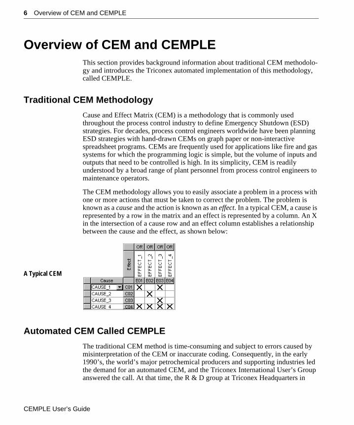
The CEM methodology allows you to easily associate a problem in a process with one or more actions that must be taken to correct the problem. The problem is known as a cause and the action is known as an effect. In a typical CEM, a cause is represented by a row in the matrix and an effect is represented by a column. An X in the intersection of a cause row and an effect column establishes a relationship between the cause and the effect, as shown below:
A Typical CEM
Automated CEM Called CEMPLE
The traditional CEM method is time-consuming and subject to errors caused by misinterpretation of the CEM or inaccurate coding. Consequently, in the early 1990’s, the world’s major petrochemical producers and supporting industries led the demand for an automated CEM, and the Triconex International User’s Group answered the call. At that time, the R & D group at Triconex Headquarters in
CEMPLE User’s Guide
Overview of CEM and CEMPLE 7
Irvine, California was in the process of developing the leading-edge TriStation 1131 Developer’s Workbench which initially offered three standard programming language editors. With the second major release of TriStation, Triconex automated the CEM methodology by adding the easy-to-use Cause & Effect Matrix Programming Language Editor (CEMPLE) to the existing suite of language editors.
CEMPLE Functionality
CEMPLE provides a matrix with two dimensions which are specifically intended for the development of safety shutdown applications:
• Each Cause Row (horizontal dimension) maps a cause to one or more effects.
• Each Effect Column (vertical dimension) maps an effect from one or more causes.
In a CEM, causes are typically represented by BOOL program input variables and effects are represented by BOOL program output variables. Once a CEM is defined, it automatically generates an FBD program which implements the ESD strategy.
CEMPLE Features
The main features offered by CEMPLE are:
• Invocation of functions and function blocks for evaluation of cause and effect data
• Choice of energize-to-trip (OR’d intersections) or de-energize-to-trip (AND’d intersections) matrix evaluation
• Support for up to 99 Cause Rows, 99 Effect Columns, and a maximum of 1000 active intersections in CEM
• Multiple levels of undo and redo selectable from an edit transaction list, limited only by the size of your hard disk
• Use of Function Block Diagram (FBD) as the intermediate language
• Use of CEM program instances in conjunction with FBD and LD program instances
• Instance view monitoring with active causes, intersections and effects displayed in your choice of colors
• Named views for specific sets of causes and effects
Chapter 1 Introduction
8 Overview of CEM and CEMPLE
CEMPLE Training
In addition to the how-to and reference material provided by this manual, Triconex offers training classes internationally to speed the transition from manual and non-interactive matrixes to state-of-the-art CEM programming with CEMPLE. For information about training, please contact the Customer Satisfaction Group at Triconex Headquarters in Irvine California. See “Technical Support” on page 13 for phone numbers.
Summary of Chapters
This manual is organized into the following chapters:
• Chapter 1, “Introduction” — Provides background information about CEM methodology; briefly defines the CEMPLE product; lists requirements for user experience; gives instructions for installing CEMPLE; and tells how to contact Triconex.
• Chapter 2, “Functional Description” — Describes the main components of CEMPLE; states the limits of CEM programs; and explains how they are evaluated.
• Chapter 3, “CEMPLE Options and Editing Tools” — Describes the basic options, tools and techniques that CEMPLE provides for editing of CEMs.
• Chapter 4, “Developing CEM Programs” — Explains how to set CEM default options and create CEM functions and function blocks; provides step-by-step instructions for creating four types of matrixes; and shows how to monitor the execution of a matrix.
• Chapter 5, “Advanced Techniques and Accessory Features” — Provides information you need to define your own functions and function blocks; explains how to share the values of Cause State and Effect State variables elsewhere in your logic; and provides tips on using the View Manager, viewing intermediate code and printing cross-reference listings.
• Appendix A, “CEM-Specific Error Messages” — Lists CEM-specific error messages with causes and solutions.
• “Glossary” — Gives brief definitions of CEM-specific terms used in the manual.
• Index
CEMPLE User’s Guide
User Experience Requirements 9
Related Documents
The following Triconex manuals contain information that is relevant to using CEMPLE:
• Developer’s Guide for Trident Systems
• Trident Planning & Installation Guide
• Triconex Libraries
User Experience RequirementsTo effectively use CEMPLE, you should already know how to use the TriStation 1131 Developer’s Workbench and be familiar with Microsoft Windows NT 4.0.
Installing the CEMPLE Add-onCEMPLE (model 7223) is an add-on product for the TriStation 1131 Developer’s Workbench (model 7223). The setup program on the CEMPLE CD installs all of the necessary components for using CEMPLE with TriStation. See the Getting Started manual for installation instructions. Please contact Triconex for more information about the available CEMPLE add-on and TriStation products.
Chapter 1 Introduction
10 Document Conventions
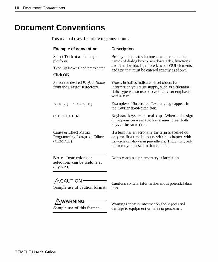
Document ConventionsThis manual uses the following conventions:
Example of convention Description
Select Trident as the target platform.
Type UpDown1 and press enter.
Click OK.
Bold type indicates buttons, menu commands, names of dialog boxes, windows, tabs, functions and function blocks, miscellaneous GUI elements; and text that must be entered exactly as shown.
Select the desired Project Name from the Project Directory.
Words in italics indicate placeholders for information you must supply, such as a filename. Italic type is also used occasionally for emphasis within text.
SIN(A) * COS(B) Examples of Structured Text language appear in the Courier fixed-pitch font.
CTRL+ ENTER Keyboard keys are in small caps. When a plus sign (+) appears between two key names, press both keys at the same time.
Cause & Effect Matrix Programming Language Editor (CEMPLE)
If a term has an acronym, the term is spelled out only the first time it occurs within a chapter, with its acronym shown in parenthesis. Thereafter, only the acronym is used in that chapter.
Note Instructions or selections can be undone at any step.
Notes contain supplementary information.
! CAUTIONSample use of caution format.
Cautions contain information about potential data loss
! WARNINGSample use of this format.
Warnings contain information about potential damage to equipment or harm to personnel.
CEMPLE User’s Guide
How to Contact Triconex 11
How to Contact TriconexYou can obtain sales information and technical support for TriStation from any regional customer center or from corporate headquarters.
Regional Customer Centers
Americas Customer Center4916 FM 1765La Marque, Texas 77568United States of America
Tel: +1-409-935-3555Fax: +1-409-935-3881
European/African Customer Center (France)10, Avenue du CentaureBP 8409 Cergy95806 Cergy Pontoise CedexFrance
Tel: +33-1-34-43-26-26Fax: +33-1-34-43-26-27
Middle East Customer Center (UAE)Rashid Al Majid BuildingAirport RoadP.O. Box 62051Dubai, United Arab Emirates
Tel: +971-4-869-555Fax: +971-4-869-955
European/African Customer Center (UK)Windsor HouseMillbrook WayColnbrook, SloughBerkshire SL3 OHNUnited Kingdom
Tel: +44-1753-684680Fax: +44-1753-686061
Middle East Sales & Service (Saudi)Saudi NationalP.O. Box 1557Corner of Prince Mohammed and 2nd StreetAl Khobar 31952The Kingdom of Saudi Arabia
Tel: +966-3-894-0087Fax: +966-3-895-0050
Asia-Pacific Customer Center750E Chai Chee Road #07-01/02Chai Chee Industrial ParkSingapore 469005
Tel: +65-738-5488Fax: +65-738-5188
Triconex Moscow Customer CenterRyazanskyi Avenue, 8AOffice 310Moscow, Russia 109 428
Tel: +70.95.2320568Fax: +70.95.2320567
Chapter 1 Introduction
12 How to Contact Triconex
Corporate Headquarters
Triconex Corporation15091 Bake ParkwayIrvine, CA 92618USA
Phones: 800-325-2128949-699-2100
Sales Department
Sales hours at Corporate Headquarters are 8:00 AM to 5:00 PM Pacific Standard Time (PST).
Phone: 949-699-2184Fax: 949-768-6601
CEMPLE User’s Guide
Technical Support 13
Technical SupportYou can obtain technical support from any regional office, as well as corporate headquarters, by telephone or fax. You can also find technical support information on the Triconex Internet web site (http://www.triconex.com).
Before requesting technical support, please attempt to solve any problems by referring to this manual, related manuals, or the online Help system. Always contact your regional office first.
Telephone
You can reach Technical Support at Corporate Headquarters by phone between 8:00 AM and 5:00 PM PST, Monday through Friday.
Phones: 800-325-2128949-699-2100
When you call, you should be at your computer and have your documentation with you. Be prepared to provide the following information:
• Product version number (found by selecting About TriStation 1131 on the Help menu)
• Exact wording of any messages that appear on the screen
• What you were doing when the problem occurred
• How you tried to solve the problem
After-Hours Support
After-hours product support is available outside of the normal business hours by calling Corporate Headquarters at 800-325-2128. The voice-mail system will prompt you to leave a detailed message, including:
• Your name and company name
• Your location (for example, city, state, country)
• Your phone number (including area code and country code, if applicable)
• The time you called
If you select the emergency option, the on-call Technical Support Manager will be contacted automatically and will return your call as soon as possible.
Chapter 1 Introduction
14 Technical Support
After-hours technical support is billed at the rate identified in the current Customer Satisfaction Price List.
Fax
Fax questions or comments to the Technical Support Manager.
Fax: 949-768-6601
Please provide the following information in your fax when describing a system problem:
• Product version number (found by selecting About TriStation 1131 on the Help menu)
• Exact wording of any messages that appear on the screen
• What you were doing when the problem occurred
• How you tried to solve the problem
Triconex Web Site
Read and download the latest information on Triconex, Triconex products, and TriStation at:
http://www.triconex.com
CEMPLE User’s Guide
C H A P T E R 2
Functional Description
This chapter provides basic information about CEM functionality, covering the following topics:
“Main Components” . . . . . . . . . . . . . . . . . . . . . . . . . . . . . . . . . . . . . 16
“Limits of CEM Programs” . . . . . . . . . . . . . . . . . . . . . . . . . . . . . . . 20
“Evaluation of CEM Programs” . . . . . . . . . . . . . . . . . . . . . . . . . . . . 21
CEMPLE User’s Guide
16 Main Components
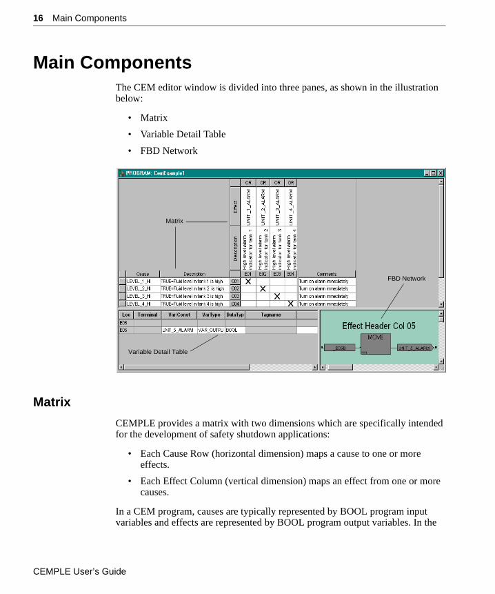
Main ComponentsThe CEM editor window is divided into three panes, as shown in the illustration below:
• Matrix
• Variable Detail Table
• FBD Network
Matrix
CEMPLE provides a matrix with two dimensions which are specifically intended for the development of safety shutdown applications:
• Each Cause Row (horizontal dimension) maps a cause to one or more effects.
• Each Effect Column (vertical dimension) maps an effect from one or more causes.
In a CEM program, causes are typically represented by BOOL program input variables and effects are represented by BOOL program output variables. In the
Matrix
Variable Detail Table
FBD Network
CEMPLE User’s Guide
Main Components 17
example shown above, LEVEL_1_HI is a BOOL program input (VAR_IN) and UNIT_1_ALARM is a BOOL program output (VAR_OUT).
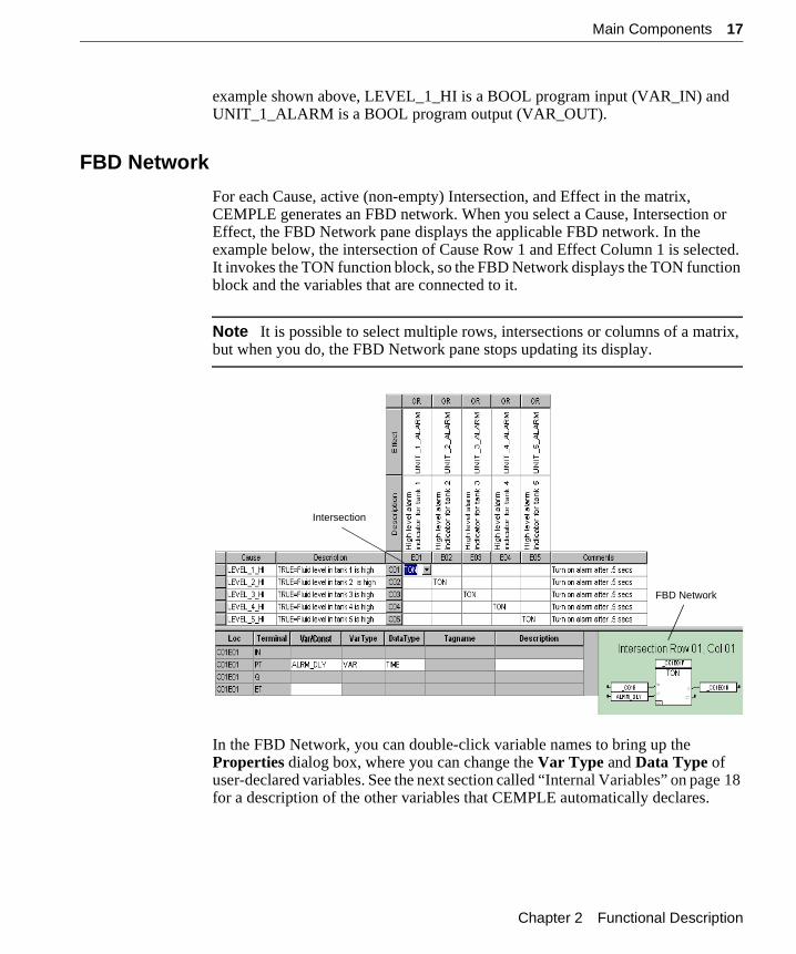
FBD Network
For each Cause, active (non-empty) Intersection, and Effect in the matrix, CEMPLE generates an FBD network. When you select a Cause, Intersection or Effect, the FBD Network pane displays the applicable FBD network. In the example below, the intersection of Cause Row 1 and Effect Column 1 is selected. It invokes the TON function block, so the FBD Network displays the TON function block and the variables that are connected to it.
Note It is possible to select multiple rows, intersections or columns of a matrix, but when you do, the FBD Network pane stops updating its display.
In the FBD Network, you can double-click variable names to bring up the Properties dialog box, where you can change the Var Type and Data Type of user-declared variables. See the next section called “Internal Variables” on page 18 for a description of the other variables that CEMPLE automatically declares.
FBD Network
Intersection
Chapter 2 Functional Description
18 Main Components
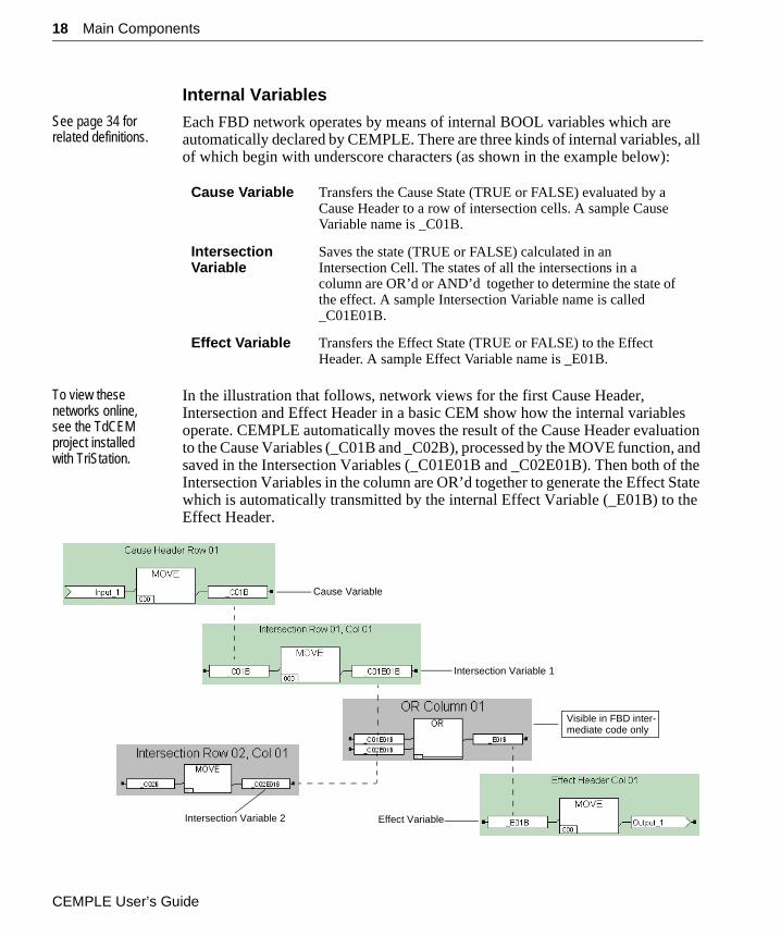
Internal VariablesSee page 34 for related definitions.
Each FBD network operates by means of internal BOOL variables which are automatically declared by CEMPLE. There are three kinds of internal variables, all of which begin with underscore characters (as shown in the example below):
To view these networks online, see the TdCEM project installed with TriStation.
In the illustration that follows, network views for the first Cause Header, Intersection and Effect Header in a basic CEM show how the internal variables operate. CEMPLE automatically moves the result of the Cause Header evaluation to the Cause Variables (_C01B and _C02B), processed by the MOVE function, and saved in the Intersection Variables (_C01E01B and _C02E01B). Then both of the Intersection Variables in the column are OR’d together to generate the Effect State which is automatically transmitted by the internal Effect Variable (_E01B) to the Effect Header.
Cause Variable Transfers the Cause State (TRUE or FALSE) evaluated by a Cause Header to a row of intersection cells. A sample Cause Variable name is _C01B.
Intersection Variable
Saves the state (TRUE or FALSE) calculated in an Intersection Cell. The states of all the intersections in a column are OR’d or AND’d together to determine the state of the effect. A sample Intersection Variable name is called _C01E01B.
Effect Variable Transfers the Effect State (TRUE or FALSE) to the Effect Header. A sample Effect Variable name is _E01B.
Cause Variable
Intersection Variable 1
Effect Variable
Visible in FBD inter-mediate code only
Intersection Variable 2
CEMPLE User’s Guide
Main Components 19
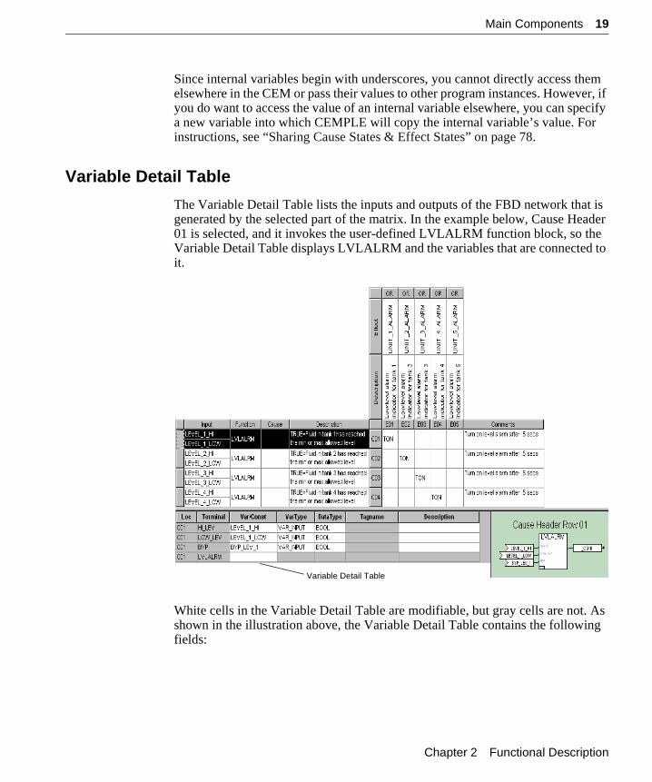
Since internal variables begin with underscores, you cannot directly access them elsewhere in the CEM or pass their values to other program instances. However, if you do want to access the value of an internal variable elsewhere, you can specify a new variable into which CEMPLE will copy the internal variable’s value. For instructions, see “Sharing Cause States & Effect States” on page 78.
Variable Detail Table
The Variable Detail Table lists the inputs and outputs of the FBD network that is generated by the selected part of the matrix. In the example below, Cause Header 01 is selected, and it invokes the user-defined LVLALRM function block, so the Variable Detail Table displays LVLALRM and the variables that are connected to it.
White cells in the Variable Detail Table are modifiable, but gray cells are not. As shown in the illustration above, the Variable Detail Table contains the following fields:
Variable Detail Table
Chapter 2 Functional Description
20 Limits of CEM Programs
Limits of CEM ProgramsA CEM program can support a maximum of:
• 99 Cause Rows
• 99 Effect Columns
• 1000 active (non-empty) Intersections
Loc Gives the coordinates for the location of an element in terms of cause row and/or effect column. For example, the name C01 in the Loc column identifies Cause Row 1 (shown above), whereas the name C02E02 would identify the intersection of Cause Row 2 and Effect Column 2.
Terminal Lists the names of the input and/or output terminals for the function or function block invoked by the selected cause header, effect header, or intersection header.
Note Extensible functions do not have terminal names.
Var/Const Shows the names of the variables connected to the terminals of the selected function/function block. Only variables named by the user are shown, whereas the internal variables declared by CEMPLE are hidden.
VarType Tells whether the connected variable is a VAR, VAR_IN or VAR_OUT.
Note VAR_IN_OUT variables are not permitted in CEM programs, function blocks that are invoked by CEM programs, or any safety program or function block.
DataType Shows the data type of the connected variable.
Monitor This field is visible only in an instance view. A box that must be checkmarked if you want to monitor the value of the variable in an instance view.
Value This field is visible only in an instance view. The value of a variable during Trident execution or emulation.
Description User-defined text that describes an individual variable.
CEMPLE User’s Guide
Evaluation of CEM Programs 21
Evaluation of CEM ProgramsTwo aspects of CEM evaluation deserve mention here: types of evaluation and order of evaluation.
Types of Matrix Evaluation
Traditionally, CEMs have been evaluated with OR’d or AND’d intersections depending on the type of application:
A trip is a safety-related shutdown of a controlled process.
• An energize-to-trip application, which uses OR’d intersections, must energize (apply power to) a specific device in order to cause a trip.
• A de-energize-to-trip application, which uses AND’d intersections, must de-energize (remove power from) a specific device in order to cause a trip.
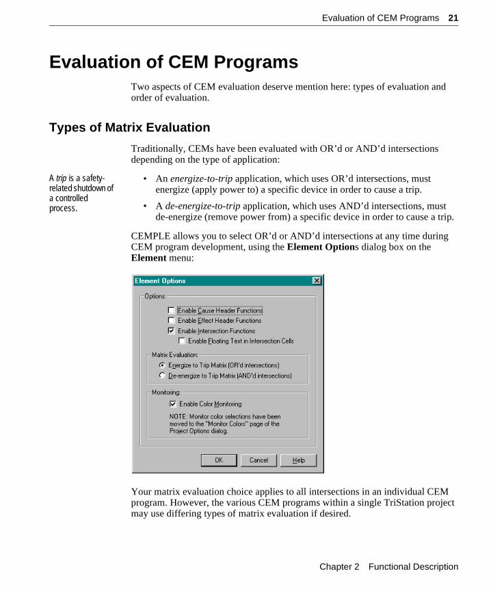
CEMPLE allows you to select OR’d or AND’d intersections at any time during CEM program development, using the Element Options dialog box on the Element menu:
Your matrix evaluation choice applies to all intersections in an individual CEM program. However, the various CEM programs within a single TriStation project may use differing types of matrix evaluation if desired.
Chapter 2 Functional Description
22 Evaluation of CEM Programs
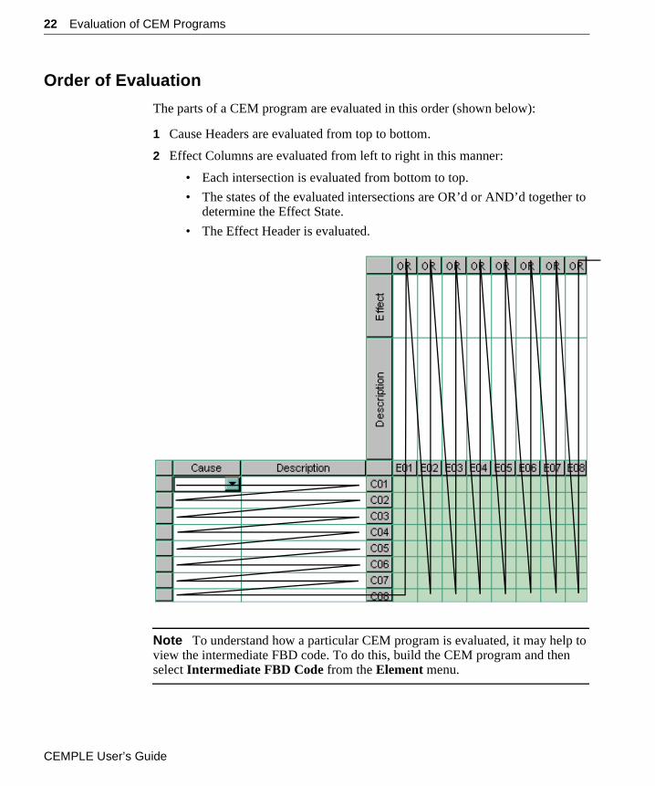
Order of Evaluation
The parts of a CEM program are evaluated in this order (shown below):
1 Cause Headers are evaluated from top to bottom.
2 Effect Columns are evaluated from left to right in this manner:
• Each intersection is evaluated from bottom to top.
• The states of the evaluated intersections are OR’d or AND’d together to determine the Effect State.
• The Effect Header is evaluated.
Note To understand how a particular CEM program is evaluated, it may help to view the intermediate FBD code. To do this, build the CEM program and then select Intermediate FBD Code from the Element menu.
CEMPLE User’s Guide
C H A P T E R 3
CEMPLE Options and Editing Tools
This chapter describes the tools and techniques that CEMPLE provides for developing and editing CEM programs. The following topics are covered:
“CEMPLE Menus & Toolbar” . . . . . . . . . . . . . . . . . . . . . . . . . . . . . 24
“Editing a Matrix” . . . . . . . . . . . . . . . . . . . . . . . . . . . . . . . . . . . . . . . 33
“Editing the Variable Detail Table” . . . . . . . . . . . . . . . . . . . . . . . . . 40
“Editing the FBD Network” . . . . . . . . . . . . . . . . . . . . . . . . . . . . . . . 43
“Setting Defaults for All CEM Programs” . . . . . . . . . . . . . . . . . . . . 45
CEMPLE User’s Guide
24 CEMPLE Menus & Toolbar
CEMPLE Menus & ToolbarTo help you edit CEM programs, TriStation provides commands that you can select from a pop-up menu, main menu and toolbar.
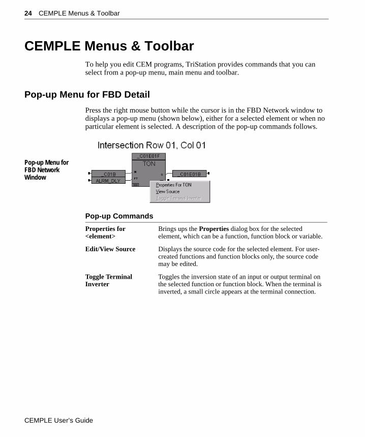
Pop-up Menu for FBD Detail
Press the right mouse button while the cursor is in the FBD Network window to displays a pop-up menu (shown below), either for a selected element or when no particular element is selected. A description of the pop-up commands follows.
Pop-up Menu for FBD Network Window
Pop-up Commands
Properties for <element>
Brings ups the Properties dialog box for the selected element, which can be a function, function block or variable.
Edit/View Source Displays the source code for the selected element. For user-created functions and function blocks only, the source code may be edited.
Toggle Terminal Inverter
Toggles the inversion state of an input or output terminal on the selected function or function block. When the terminal is inverted, a small circle appears at the terminal connection.
CEMPLE User’s Guide
CEMPLE Menus & Toolbar 25
Main Menu Commands
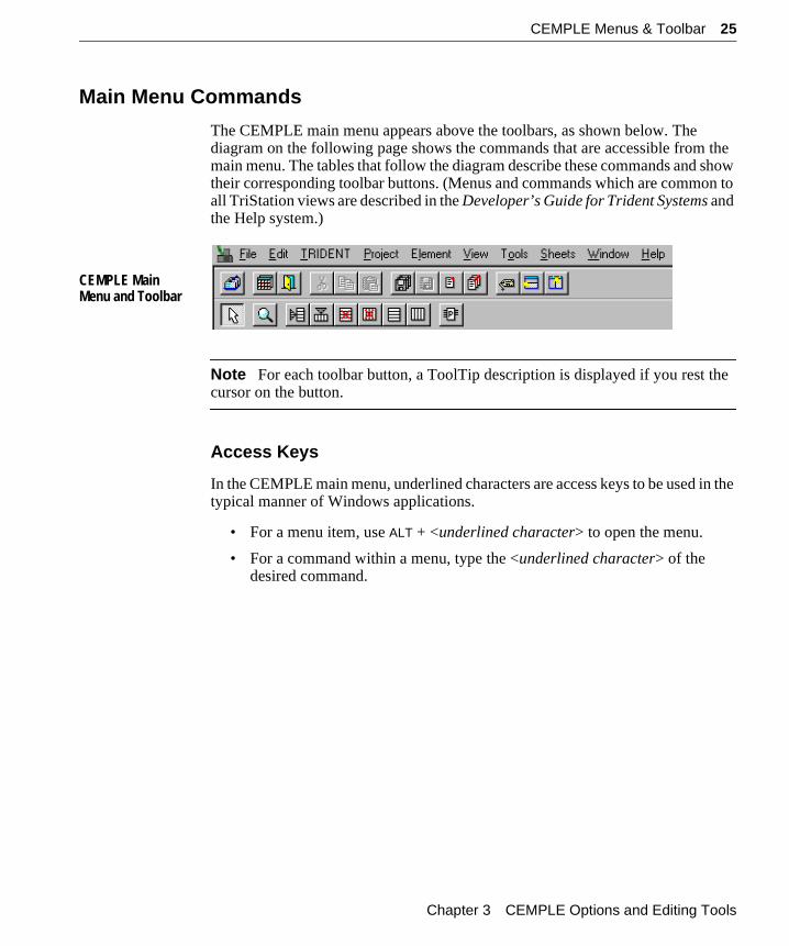
The CEMPLE main menu appears above the toolbars, as shown below. The diagram on the following page shows the commands that are accessible from the main menu. The tables that follow the diagram describe these commands and show their corresponding toolbar buttons. (Menus and commands which are common to all TriStation views are described in the Developer’s Guide for Trident Systems and the Help system.)
CEMPLE Main Menu and Toolbar
Note For each toolbar button, a ToolTip description is displayed if you rest the cursor on the button.
Access Keys
In the CEMPLE main menu, underlined characters are access keys to be used in the typical manner of Windows applications.
• For a menu item, use ALT + <underlined character> to open the menu.
• For a command within a menu, type the <underlined character> of the desired command.
Chapter 3 CEMPLE Options and Editing Tools
26 CEMPLE Menus & Toolbar
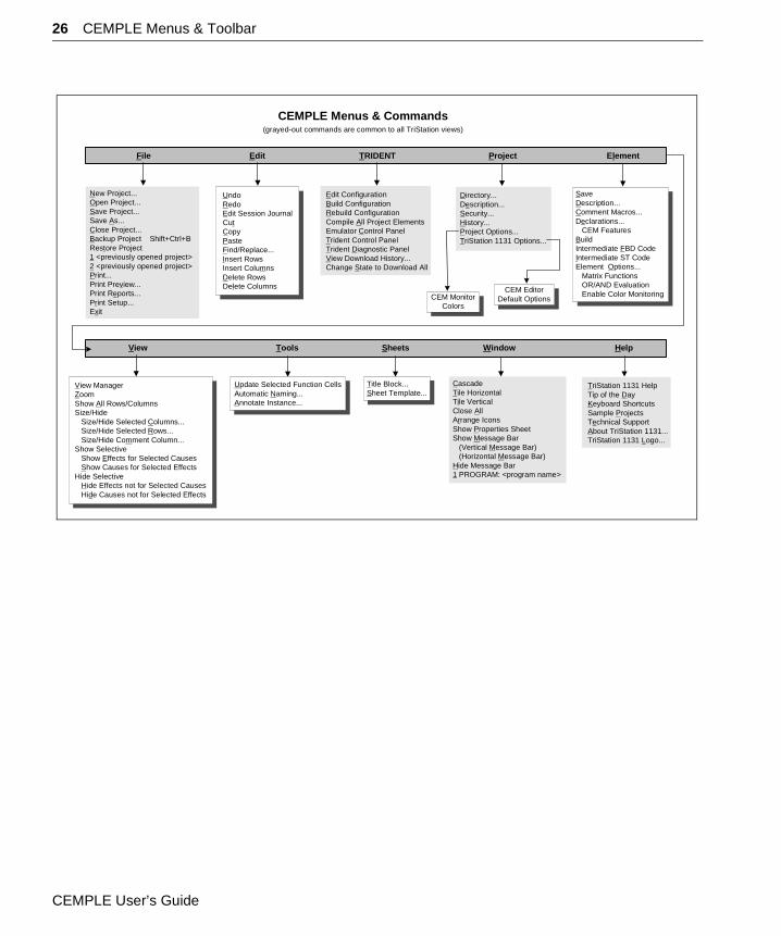
Edit ConfigurationBuild ConfigurationRebuild ConfigurationCompile All Project ElementsEmulator Control PanelTrident Control PanelTrident Diagnostic PanelView Download History...Change State to Download All
Edit TRIDENT Project Element
Tools Window Help
New Project...Open Project...Save Project...Save As...Close Project...Backup Project Shift+Ctrl+BRestore Project1 <previously opened project>2 <previously opened project>Print...Print Preview...Print Reports...Print Setup...Exit
UndoRedoEdit Session JournalCutCopyPasteFind/Replace...Insert RowsInsert ColumnsDelete RowsDelete Columns
Directory...Description...Security...History...Project Options...TriStation 1131 Options...
SaveDescription...Comment Macros...Declarations... CEM FeaturesBuildIntermediate FBD CodeIntermediate ST CodeElement Options... Matrix Functions OR/AND Evaluation Enable Color Monitoring
File
View
CEMPLE Menus & Commands(grayed-out commands are common to all TriStation views)
Update Selected Function CellsAutomatic Naming...Annotate Instance...
View ManagerZoomShow All Rows/ColumnsSize/Hide Size/Hide Selected Columns... Size/Hide Selected Rows... Size/Hide Comment Column...Show Selective Show Effects for Selected Causes Show Causes for Selected EffectsHide Selective Hide Effects not for Selected Causes Hide Causes not for Selected Effects
CascadeTile HorizontalTile VerticalClose AllArrange IconsShow Properties SheetShow Message Bar (Vertical Message Bar) (Horizontal Message Bar)Hide Message Bar1 PROGRAM: <program name>
TriStation 1131 HelpTip of the DayKeyboard ShortcutsSample ProjectsTechnical SupportAbout TriStation 1131...TriStation 1131 Logo...
CEM MonitorColors
CEM EditorDefault Options
Sheets
Title Block...Sheet Template...
CEMPLE User’s Guide
CEMPLE Menus & Toolbar 27
Table of CEMPLE Tools
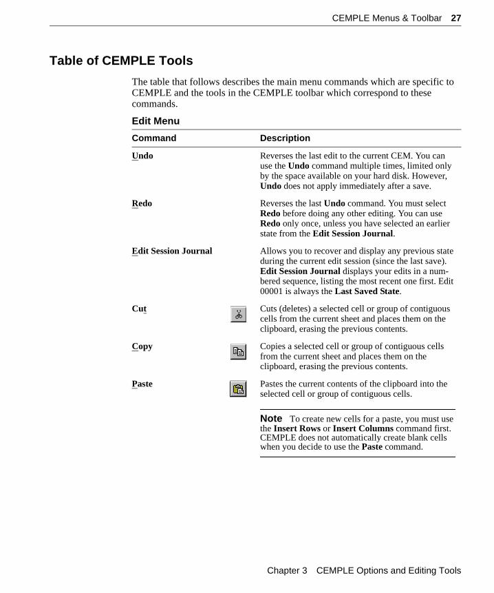
The table that follows describes the main menu commands which are specific to CEMPLE and the tools in the CEMPLE toolbar which correspond to these commands.
Edit Menu
Command Description
Undo Reverses the last edit to the current CEM. You can use the Undo command multiple times, limited only by the space available on your hard disk. However, Undo does not apply immediately after a save.
Redo Reverses the last Undo command. You must select Redo before doing any other editing. You can use Redo only once, unless you have selected an earlier state from the Edit Session Journal.
Edit Session Journal Allows you to recover and display any previous state during the current edit session (since the last save). Edit Session Journal displays your edits in a num-bered sequence, listing the most recent one first. Edit 00001 is always the Last Saved State.
Cut Cuts (deletes) a selected cell or group of contiguous cells from the current sheet and places them on the clipboard, erasing the previous contents.
Copy Copies a selected cell or group of contiguous cells from the current sheet and places them on the clipboard, erasing the previous contents.
Paste Pastes the current contents of the clipboard into the selected cell or group of contiguous cells.
Note To create new cells for a paste, you must use the Insert Rows or Insert Columns command first. CEMPLE does not automatically create blank cells when you decide to use the Paste command.
Chapter 3 CEMPLE Options and Editing Tools
28 CEMPLE Menus & Toolbar
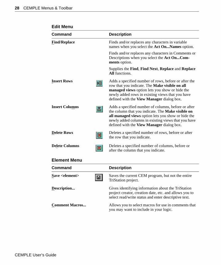
Find/Replace Finds and/or replaces any characters in variable names when you select the Act On...Names option.
Finds and/or replaces any characters in Comments or Descriptions when you select the Act On...Com-ments option.
Supplies the Find, Find Next, Replace and Replace All functions.
Insert Rows Adds a specified number of rows, before or after the row that you indicate. The Make visible on all managed views option lets you show or hide the newly added rows in existing views that you have defined with the View Manager dialog box.
Insert Columns Adds a specified number of columns, before or after the column that you indicate. The Make visible on all managed views option lets you show or hide the newly added columns in existing views that you have defined with the View Manager dialog box.
Delete Rows Deletes a specified number of rows, before or after the row that you indicate.
Delete Columns Deletes a specified number of columns, before or after the column that you indicate.
Element Menu
Command Description
Save <element> Saves the current CEM program, but not the entire TriStation project.
Description... Gives identifying information about the TriStation project creator, creation date, etc. and allows you to select read/write status and enter descriptive text.
Comment Macros... Allows you to select macros for use in comments that you may want to include in your logic.
Edit Menu
Command Description
CEMPLE User’s Guide
CEMPLE Menus & Toolbar 29
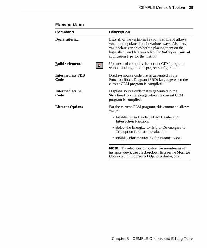
Declarations... Lists all of the variables in your matrix and allows you to manipulate them in various ways. Also lets you declare variables before placing them on the logic sheet, and lets you select the Safety or Control application type for the matrix.
Build <element> Updates and compiles the current CEM program without linking it to the project configuration.
Intermediate FBD Code
Displays source code that is generated in the Function Block Diagram (FBD) language when the current CEM program is compiled.
Intermediate ST Code
Displays source code that is generated in the Structured Text language when the current CEM program is compiled.
Element Options For the current CEM program, this command allows you to:
• Enable Cause Header, Effect Header and Intersection functions
• Select the Energize-to-Trip or De-energize-to-Trip option for matrix evaluation
• Enable color monitoring for instance views
Note To select custom colors for monitoring of instance views, use the dropdown lists on the Monitor Colors tab of the Project Options dialog box.
Element Menu
Command Description
Chapter 3 CEMPLE Options and Editing Tools
30 CEMPLE Menus & Toolbar
View Menu
Command Description
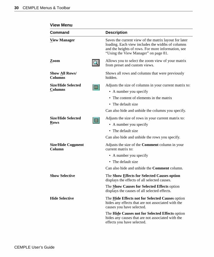
View Manager Saves the current view of the matrix layout for later loading. Each view includes the widths of columns and the heights of rows. For more information, see “Using the View Manager” on page 81.
Zoom Allows you to select the zoom view of your matrix from preset and custom views.
Show All Rows/Columns
Shows all rows and columns that were previously hidden.
Size/Hide Selected Columns
Adjusts the size of columns in your current matrix to:
• A number you specify
• The content of elements in the matrix
• The default size
Can also hide and unhide the columns you specify.
Size/Hide Selected Rows
Adjusts the size of rows in your current matrix to:
• A number you specify
• The default size
Can also hide and unhide the rows you specify.
Size/Hide Comment Column
Adjusts the size of the Comment column in your current matrix to:
• A number you specify
• The default size
Can also hide and unhide the Comment column.
Show Selective The Show Effects for Selected Causes option displays the effects of all selected causes.
The Show Causes for Selected Effects option displays the causes of all selected effects.
Hide Selective The Hide Effects not for Selected Causes option hides any effects that are not associated with the causes you have selected.
The Hide Causes not for Selected Effects option hides any causes that are not associated with the effects you have selected.
CEMPLE User’s Guide
CEMPLE Menus & Toolbar 31
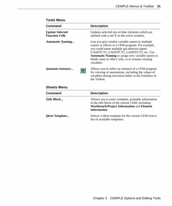
Tools Menu
Command Description
Update Selected Function Cells
Updates selected out-of-date elements which are marked with a red X in the active window.
Automatic Naming... Lets you give similar variable names to multiple causes or effects in a CEM program. For example, you could name multiple gas detector inputs GASDTCT1, GASDTCT2, GASDTCT3, etc. Use Automatic Naming to assign new variable names to blank cause or effect cells, or to rename existing variables.
Annotate Instance... Allows you to select an instance of a CEM program for viewing of annotations, including the values of variables during execution either in the Emulator or the Trident.
Sheets Menu
Command Description
Title Block... Allows you to enter complete, printable information in the title block of the current CEM, including Workbench/Project Information and Element Information.
Sheet Template... Selects a sheet template for the current CEM from a list of available templates.
Chapter 3 CEMPLE Options and Editing Tools
32 CEMPLE Menus & Toolbar
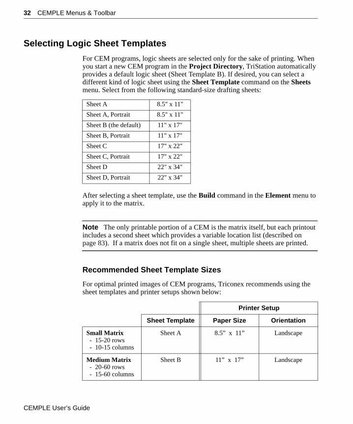
Selecting Logic Sheet Templates
For CEM programs, logic sheets are selected only for the sake of printing. When you start a new CEM program in the Project Directory, TriStation automatically provides a default logic sheet (Sheet Template B). If desired, you can select a different kind of logic sheet using the Sheet Template command on the Sheets menu. Select from the following standard-size drafting sheets:
After selecting a sheet template, use the Build command in the Element menu to apply it to the matrix.
Note The only printable portion of a CEM is the matrix itself, but each printout includes a second sheet which provides a variable location list (described on page 83). If a matrix does not fit on a single sheet, multiple sheets are printed.
Recommended Sheet Template Sizes
For optimal printed images of CEM programs, Triconex recommends using the sheet templates and printer setups shown below:
Sheet A 8.5" x 11"
Sheet A, Portrait 8.5" x 11"
Sheet B (the default) 11" x 17"
Sheet B, Portrait 11" x 17"
Sheet C 17" x 22"
Sheet C, Portrait 17" x 22"
Sheet D 22" x 34"
Sheet D, Portrait 22" x 34"
Printer Setup
Sheet Template Paper Size Orientation
Small Matrix - 15-20 rows - 10-15 columns
Sheet A 8.5” x 11” Landscape
Medium Matrix - 20-60 rows - 15-60 columns
Sheet B 11” x 17” Landscape
CEMPLE User’s Guide
Editing a Matrix 33
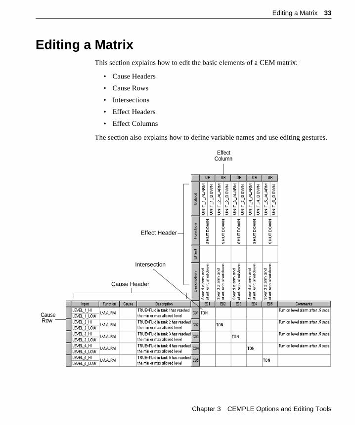
Editing a MatrixThis section explains how to edit the basic elements of a CEM matrix:
• Cause Headers
• Cause Rows
• Intersections
• Effect Headers
• Effect Columns
The section also explains how to define variable names and use editing gestures.
Cause Header
Effect Header
Intersection
EffectColumn
CauseRow
Chapter 3 CEMPLE Options and Editing Tools
34 Editing a Matrix
Cause Headers & RowsSee page 70 for details about Cause Header Functions.
A Cause Header always includes a Cause column and a Description column. If you enable Cause Header Functions, the Cause Header will also include:
• An Input cell that allows you to specify an optional variable to receive the Cause State evaluated by the Function cell
• A Function cell that allows you to invoke a Triconex library function or function block or one that is user-created
A Cause Row includes both the Cause Header and the associated set of intersections in the matrix.
IntersectionsSee page 72 for details about Intersection Functions.
The Intersection of a Cause Header and an Effect Header is present in every matrix. In the simplest type of matrix, Intersections consist only of the MOVE function (represented by an X), which moves the Cause State results to the Effect Header for processing. However, if you enable Intersection Functions, each Intersection cell will provide access to:
• A drop-down list of Triconex library functions and function blocks
• Any user-defined function or function block which you have initialized properly
Effect Headers & ColumnsSee page 74 for details about Effect Header Functions.
An Effect Header always includes an Effect column and a Description column. If you enable Effect Header Functions, the Effect Header will also include:
• An Output cell that allows you to specify an optional variable to receive the Effect State evaluated by the intersection
• A Function cell that allows you to invoke a Triconex library or user-created function or function block
An Effect Column includes both the Effect Header and the associated set of Intersections in the matrix.
Note See “Designing CEM Functions & Function Blocks” on page 70 for more information about the Cause Header Functions, Intersection Functions, and Effect Header Functions mentioned above.
CEMPLE User’s Guide
Editing a Matrix 35
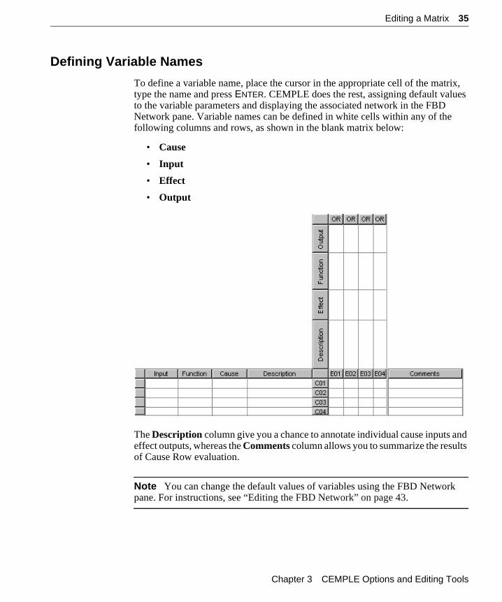
Defining Variable Names
To define a variable name, place the cursor in the appropriate cell of the matrix, type the name and press ENTER. CEMPLE does the rest, assigning default values to the variable parameters and displaying the associated network in the FBD Network pane. Variable names can be defined in white cells within any of the following columns and rows, as shown in the blank matrix below:
• Cause
• Input
• Effect
• Output
The Description column give you a chance to annotate individual cause inputs and effect outputs, whereas the Comments column allows you to summarize the results of Cause Row evaluation.
Note You can change the default values of variables using the FBD Network pane. For instructions, see “Editing the FBD Network” on page 43.
Chapter 3 CEMPLE Options and Editing Tools
36 Editing a Matrix
Editing Gestures
CEMPLE provides a complete set of gestures for selecting, editing, sizing and hiding the various parts of a matrix. Details about these activities follow.
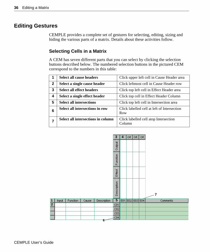
Selecting Cells in a Matrix
A CEM has seven different parts that you can select by clicking the selection buttons described below. The numbered selection buttons in the pictured CEM correspond to the numbers in this table:
1 Select all cause headers Click upper left cell in Cause Header area
2 Select a single cause header Click leftmost cell in Cause Header row
3 Select all effect headers Click top left cell in Effect Header area
4 Select a single effect header Click top cell in Effect Header Column
5 Select all intersections Click top left cell in Intersection area
6 Select all intersections in row Click labelled cell at left of Intersection Row
7 Select all intersections in column Click labelled cell atop Intersection Column
12
6
43
5
7
CEMPLE User’s Guide
Editing a Matrix 37
Selecting Multiple Cells
To select a cell without entering edit mode, use the right mouse button.
To select discontiguous cells of a matrix simultaneously: select a cell, hold down the CTRL key and click the various rows or columns that you wish to select.
To select contiguous cells simultaneously in a column or a rectangular pattern: select the first cell, hold down the SHIFT key and click the last cell in the desired area.
Editing Cells
Editing of cells in a matrix can be accomplished using four basic gestures:
Sizing, Hiding & Unhiding Cells
There are four ways to manipulate the display of cells in a matrix:
• Change their size—that is, the width of columns or the height of rows
• Hide rows or columns so they’re not displayed at all
• Unhide hidden rows or columns to the display
• Restore the default sizes of columns or rows
Enter edit mode Click directly over the text in an editable cell, then edit the contents.
Note To select a cell without entering edit mode, click the right mouse button anywhere in the cell.
Complete a cell entry Press the TAB key or ENTER key to complete a cell entry and move the cursor to the next cell to the right.
Move to the next cell Press the TAB key or ENTER key to move the cursor to the next cell to the right.
Delete contents of a cell or group of cells
Select a cell or group of cells (but do not place in edit mode) and press the DELETE key.
Note To select a cell without entering edit mode, click the right mouse button anywhere in the cell.
Chapter 3 CEMPLE Options and Editing Tools
38 Editing a Matrix
In general, the actions you can take to manipulate cell display are:
• Dragging boundaries to change cell width or height or restore the default size, using the double-arrow cursor
• Double-clicking thickened boundaries (shown below) to unhide hidden columns or rows
• Using the Size/Hide commands on the View menu to change the width or height and hide or unhide selected cells
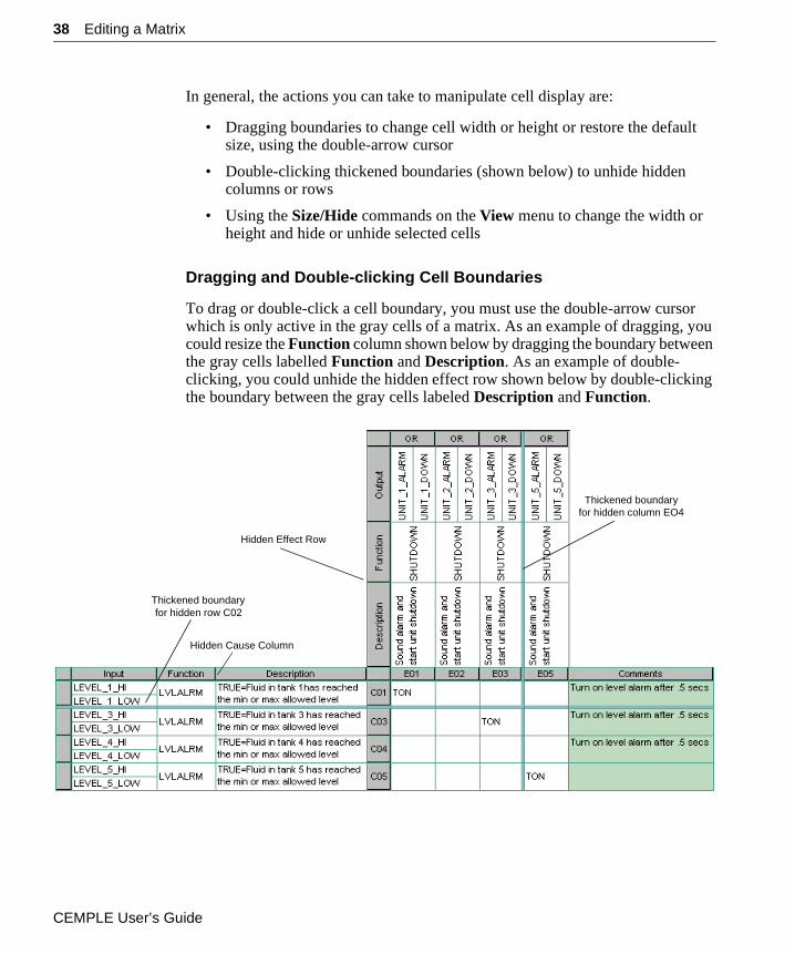
Dragging and Double-clicking Cell Boundaries
To drag or double-click a cell boundary, you must use the double-arrow cursor which is only active in the gray cells of a matrix. As an example of dragging, you could resize the Function column shown below by dragging the boundary between the gray cells labelled Function and Description. As an example of double-clicking, you could unhide the hidden effect row shown below by double-clicking the boundary between the gray cells labeled Description and Function.
Thickened boundaryfor hidden column EO4
Thickened boundaryfor hidden row C02
Hidden Cause Column
Hidden Effect Row
CEMPLE User’s Guide
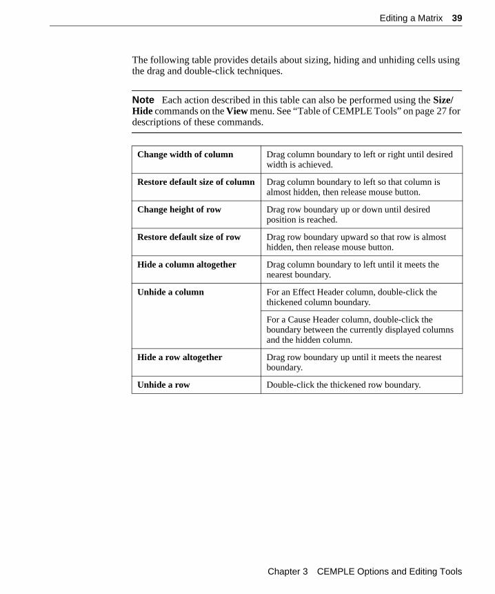
Editing a Matrix 39
The following table provides details about sizing, hiding and unhiding cells using the drag and double-click techniques.
Note Each action described in this table can also be performed using the Size/Hide commands on the View menu. See “Table of CEMPLE Tools” on page 27 for descriptions of these commands.
Change width of column Drag column boundary to left or right until desired width is achieved.
Restore default size of column Drag column boundary to left so that column is almost hidden, then release mouse button.
Change height of row Drag row boundary up or down until desired position is reached.
Restore default size of row Drag row boundary upward so that row is almost hidden, then release mouse button.
Hide a column altogether Drag column boundary to left until it meets the nearest boundary.
Unhide a column For an Effect Header column, double-click the thickened column boundary.
For a Cause Header column, double-click the boundary between the currently displayed columns and the hidden column.
Hide a row altogether Drag row boundary up until it meets the nearest boundary.
Unhide a row Double-click the thickened row boundary.
Chapter 3 CEMPLE Options and Editing Tools
40 Editing the Variable Detail Table
Editing the Variable Detail TableThe Variable Detail Table allows you to add and modify variables for application-specific purposes in three ways:
• Assigning variables to unconnected terminals
• Changing the names of existing variables
• Sharing the values of Cause State and Effect State variables
These tasks are described in the pages that follow. However, before you undertake them, you need to understand the editing gestures that CEMPLE allows for the Variable Detail Table.
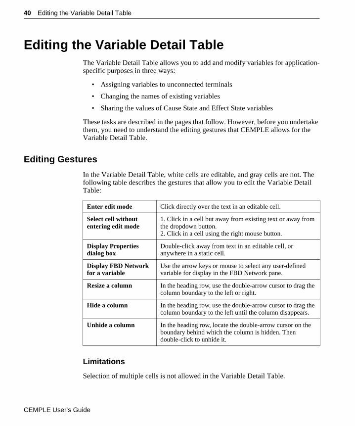
Editing Gestures
In the Variable Detail Table, white cells are editable, and gray cells are not. The following table describes the gestures that allow you to edit the Variable Detail Table:
Limitations
Selection of multiple cells is not allowed in the Variable Detail Table.
Enter edit mode Click directly over the text in an editable cell.
Select cell without entering edit mode
1. Click in a cell but away from existing text or away from the dropdown button.2. Click in a cell using the right mouse button.
Display Properties dialog box
Double-click away from text in an editable cell, or anywhere in a static cell.
Display FBD Network for a variable
Use the arrow keys or mouse to select any user-defined variable for display in the FBD Network pane.
Resize a column In the heading row, use the double-arrow cursor to drag the column boundary to the left or right.
Hide a column In the heading row, use the double-arrow cursor to drag the column boundary to the left until the column disappears.
Unhide a column In the heading row, locate the double-arrow cursor on the boundary behind which the column is hidden. Then double-click to unhide it.
CEMPLE User’s Guide
Editing the Variable Detail Table 41
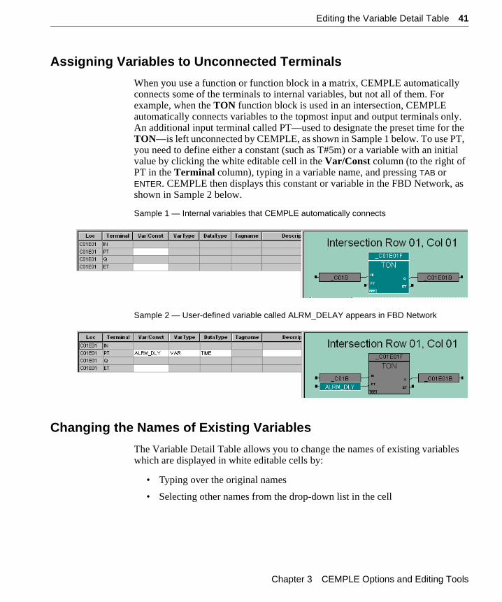
Assigning Variables to Unconnected Terminals
When you use a function or function block in a matrix, CEMPLE automatically connects some of the terminals to internal variables, but not all of them. For example, when the TON function block is used in an intersection, CEMPLE automatically connects variables to the topmost input and output terminals only. An additional input terminal called PT—used to designate the preset time for the TON—is left unconnected by CEMPLE, as shown in Sample 1 below. To use PT, you need to define either a constant (such as T#5m) or a variable with an initial value by clicking the white editable cell in the Var/Const column (to the right of PT in the Terminal column), typing in a variable name, and pressing TAB or ENTER. CEMPLE then displays this constant or variable in the FBD Network, as shown in Sample 2 below.
Sample 1 — Internal variables that CEMPLE automatically connects
Sample 2 — User-defined variable called ALRM_DELAY appears in FBD Network
Changing the Names of Existing Variables
The Variable Detail Table allows you to change the names of existing variables which are displayed in white editable cells by:
• Typing over the original names
• Selecting other names from the drop-down list in the cell
Chapter 3 CEMPLE Options and Editing Tools
42 Editing the Variable Detail Table
Sharing Cause States & Effect StatesInternal variable names are dis-played in the FBD Network pane.
One of the ways that CEMPLE stores and transmits Cause States, Intersection States and Effect States is to automatically declare its own internal variables. Each internal variable has a Var Type of Local and begins with an underscore—for example, _C01B. Like other variables in TriStation which begin with underscores, CEMPLE’s internal variables are not directly accessible. However, CEMPLE does allow you to declare your own variables for sharing the values of internal Cause State and Effect State variables elsewhere in your logic. You may enter the names for such variables in blank cells of the Variable Detail Table, and modify their properties using the Properties dialog box which is accessible from the FBD Network pane. For detailed instructions, see “Sharing Cause States & Effect States” on page 78.
Note The values of Intersection state variables cannot be shared.
CEMPLE User’s Guide
Editing the FBD Network 43
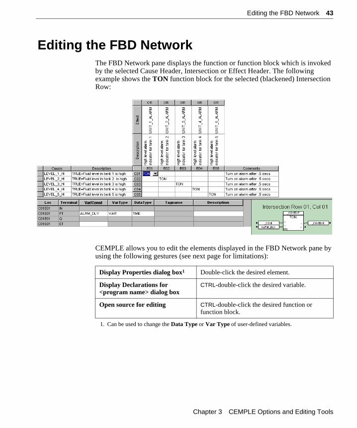
Editing the FBD NetworkThe FBD Network pane displays the function or function block which is invoked by the selected Cause Header, Intersection or Effect Header. The following example shows the TON function block for the selected (blackened) Intersection Row:
CEMPLE allows you to edit the elements displayed in the FBD Network pane by using the following gestures (see next page for limitations):
Display Properties dialog box1
1. Can be used to change the Data Type or Var Type of user-defined variables.
Double-click the desired element.
Display Declarations for <program name> dialog box
CTRL-double-click the desired variable.
Open source for editing CTRL-double-click the desired function or function block.
Chapter 3 CEMPLE Options and Editing Tools
44 Editing the FBD Network
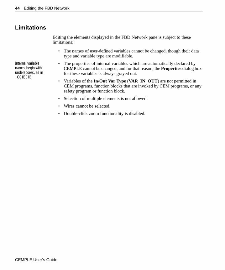
Limitations
Editing the elements displayed in the FBD Network pane is subject to these limitations:
• The names of user-defined variables cannot be changed, though their data type and variable type are modifiable.
Internal variable names begin with underscores, as in _C01E01B.
• The properties of internal variables which are automatically declared by CEMPLE cannot be changed, and for that reason, the Properties dialog box for these variables is always grayed out.
• Variables of the In/Out Var Type (VAR_IN_OUT) are not permitted in CEM programs, function blocks that are invoked by CEM programs, or any safety program or function block.
• Selection of multiple elements is not allowed.
• Wires cannot be selected.
• Double-click zoom functionality is disabled.
CEMPLE User’s Guide
Setting Defaults for All CEM Programs 45
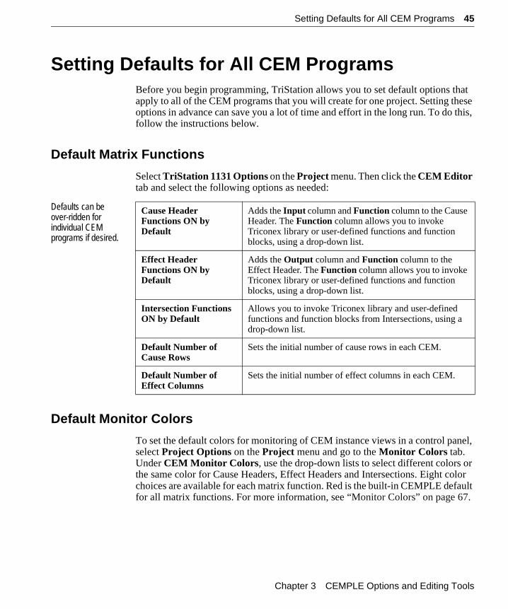
Setting Defaults for All CEM ProgramsBefore you begin programming, TriStation allows you to set default options that apply to all of the CEM programs that you will create for one project. Setting these options in advance can save you a lot of time and effort in the long run. To do this, follow the instructions below.
Default Matrix Functions
Select TriStation 1131 Options on the Project menu. Then click the CEM Editor tab and select the following options as needed:
Defaults can be over-ridden for individual CEM programs if desired.
Default Monitor Colors
To set the default colors for monitoring of CEM instance views in a control panel, select Project Options on the Project menu and go to the Monitor Colors tab. Under CEM Monitor Colors, use the drop-down lists to select different colors or the same color for Cause Headers, Effect Headers and Intersections. Eight color choices are available for each matrix function. Red is the built-in CEMPLE default for all matrix functions. For more information, see “Monitor Colors” on page 67.
Cause Header Functions ON by Default
Adds the Input column and Function column to the Cause Header. The Function column allows you to invoke Triconex library or user-defined functions and function blocks, using a drop-down list.
Effect Header Functions ON by Default
Adds the Output column and Function column to the Effect Header. The Function column allows you to invoke Triconex library or user-defined functions and function blocks, using a drop-down list.
Intersection Functions ON by Default
Allows you to invoke Triconex library and user-defined functions and function blocks from Intersections, using a drop-down list.
Default Number of Cause Rows
Sets the initial number of cause rows in each CEM.
Default Number of Effect Columns
Sets the initial number of effect columns in each CEM.
Chapter 3 CEMPLE Options and Editing Tools

46 Setting Defaults for All CEM Programs
CEMPLE User’s Guide
C H A P T E R 4
Developing CEM Programs
Programming with CEMPLE allows you to define process system alarms and shutdown actions in a very simple, easy-to-understand manner. To help you develop CEM programs that use many of the available features, this chapter provides step-by-step instructions for creating four types of matrixes. The following topics are covered:
“Setting CEM Default Options” . . . . . . . . . . . . . . . . . . . . . . . . . . . . 48
“Creating a Function” . . . . . . . . . . . . . . . . . . . . . . . . . . . . . . . . . . . . 49
“Creating a Function Block” . . . . . . . . . . . . . . . . . . . . . . . . . . . . . . . 50
“Creating a Simple Matrix” . . . . . . . . . . . . . . . . . . . . . . . . . . . . . . . 51
“Creating a Matrix with Intersection Functions” . . . . . . . . . . . . . . . 55
“Creating a Matrix with Cause Header Functions” . . . . . . . . . . . . . 59
“Creating a Matrix with Effect Header Functions” . . . . . . . . . . . . . 63
“Monitoring an Instance View” . . . . . . . . . . . . . . . . . . . . . . . . . . . . 66
Note If you installed CEMPLE on your hard disk using the default directories, the TDCEM.pt2 sample project should be located under:
C:\Program Files\Triconex\TS1131\_trident\Examples
All matrixes in the sample project use Energize-to-Trip (OR’d intersections) evaluation. To use De-Energize-to-Trip (AND’d intersections) evaluation, select it for each matrix with the Element Options command on the Element menu.
CEMPLE User’s Guide
48 Setting CEM Default Options
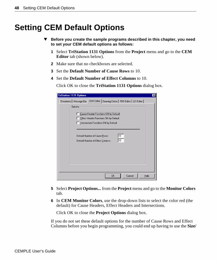
Setting CEM Default Options▼ Before you create the sample programs described in this chapter, you need
to set your CEM default options as follows:
1 Select TriStation 1131 Options from the Project menu and go to the CEM Editor tab (shown below).
2 Make sure that no checkboxes are selected.
3 Set the Default Number of Cause Rows to 10.
4 Set the Default Number of Effect Columns to 10.
Click OK to close the TriStation 1131 Options dialog box.
5 Select Project Options... from the Project menu and go to the Monitor Colors tab.
6 In CEM Monitor Colors, use the drop-down lists to select the color red (the default) for Cause Headers, Effect Headers and Intersections.
Click OK to close the Project Options dialog box.
If you do not set these default options for the number of Cause Rows and Effect Columns before you begin programming, you could end up having to use the Size/
CEMPLE User’s Guide
Creating a Function 49
Hide commands, or equivalent editing gestures, more than necessary. See “Sizing, Hiding & Unhiding Cells” on page 37 for details.
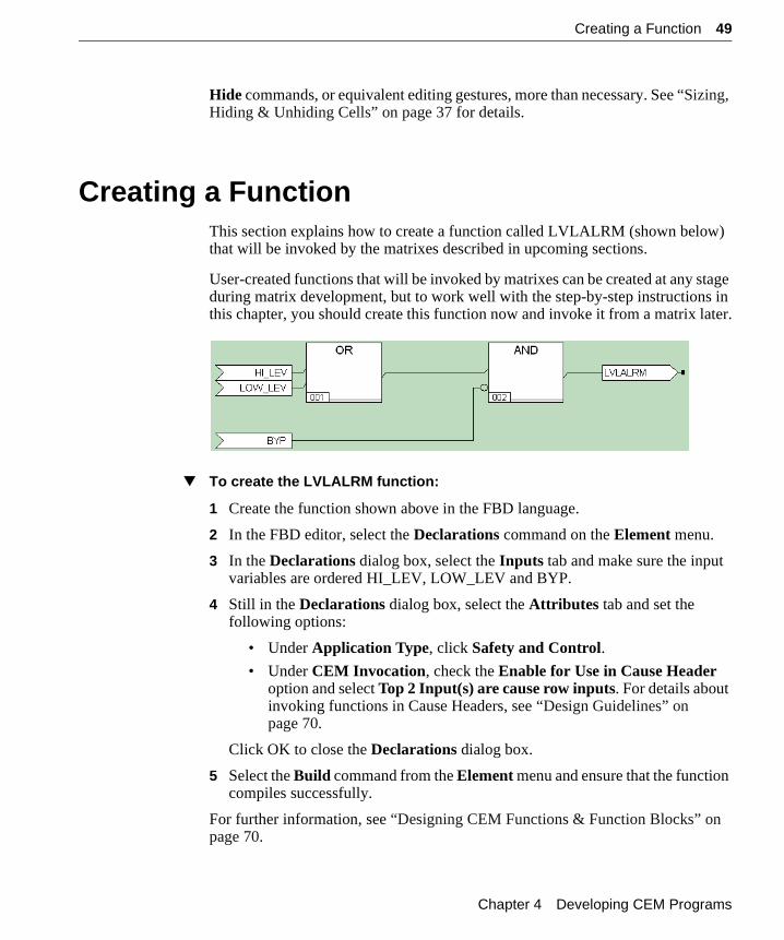
Creating a FunctionThis section explains how to create a function called LVLALRM (shown below) that will be invoked by the matrixes described in upcoming sections.
User-created functions that will be invoked by matrixes can be created at any stage during matrix development, but to work well with the step-by-step instructions in this chapter, you should create this function now and invoke it from a matrix later.
▼ To create the LVLALRM function:
1 Create the function shown above in the FBD language.
2 In the FBD editor, select the Declarations command on the Element menu.
3 In the Declarations dialog box, select the Inputs tab and make sure the input variables are ordered HI_LEV, LOW_LEV and BYP.
4 Still in the Declarations dialog box, select the Attributes tab and set the following options:
• Under Application Type, click Safety and Control.
• Under CEM Invocation, check the Enable for Use in Cause Header option and select Top 2 Input(s) are cause row inputs. For details about invoking functions in Cause Headers, see “Design Guidelines” on page 70.
Click OK to close the Declarations dialog box.
5 Select the Build command from the Element menu and ensure that the function compiles successfully.
For further information, see “Designing CEM Functions & Function Blocks” on page 70.
Chapter 4 Developing CEM Programs
50 Creating a Function Block
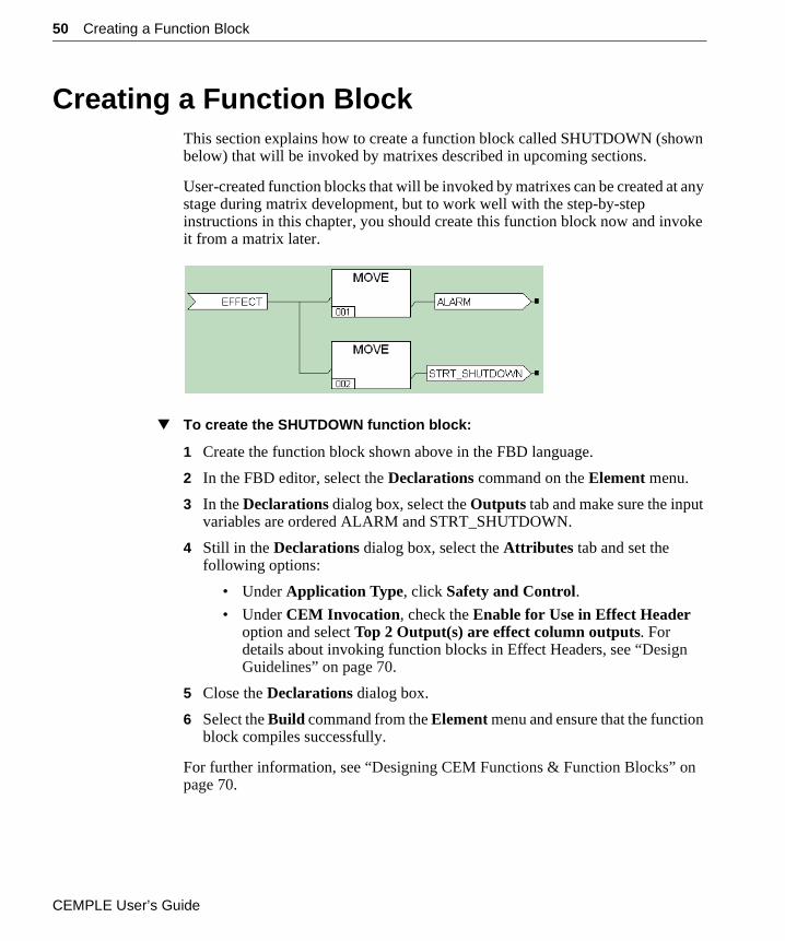
Creating a Function BlockThis section explains how to create a function block called SHUTDOWN (shown below) that will be invoked by matrixes described in upcoming sections.
User-created function blocks that will be invoked by matrixes can be created at any stage during matrix development, but to work well with the step-by-step instructions in this chapter, you should create this function block now and invoke it from a matrix later.
▼ To create the SHUTDOWN function block:
1 Create the function block shown above in the FBD language.
2 In the FBD editor, select the Declarations command on the Element menu.
3 In the Declarations dialog box, select the Outputs tab and make sure the input variables are ordered ALARM and STRT_SHUTDOWN.
4 Still in the Declarations dialog box, select the Attributes tab and set the following options:
• Under Application Type, click Safety and Control.
• Under CEM Invocation, check the Enable for Use in Effect Header option and select Top 2 Output(s) are effect column outputs. For details about invoking function blocks in Effect Headers, see “Design Guidelines” on page 70.
5 Close the Declarations dialog box.
6 Select the Build command from the Element menu and ensure that the function block compiles successfully.
For further information, see “Designing CEM Functions & Function Blocks” on page 70.
CEMPLE User’s Guide
Creating a Simple Matrix 51
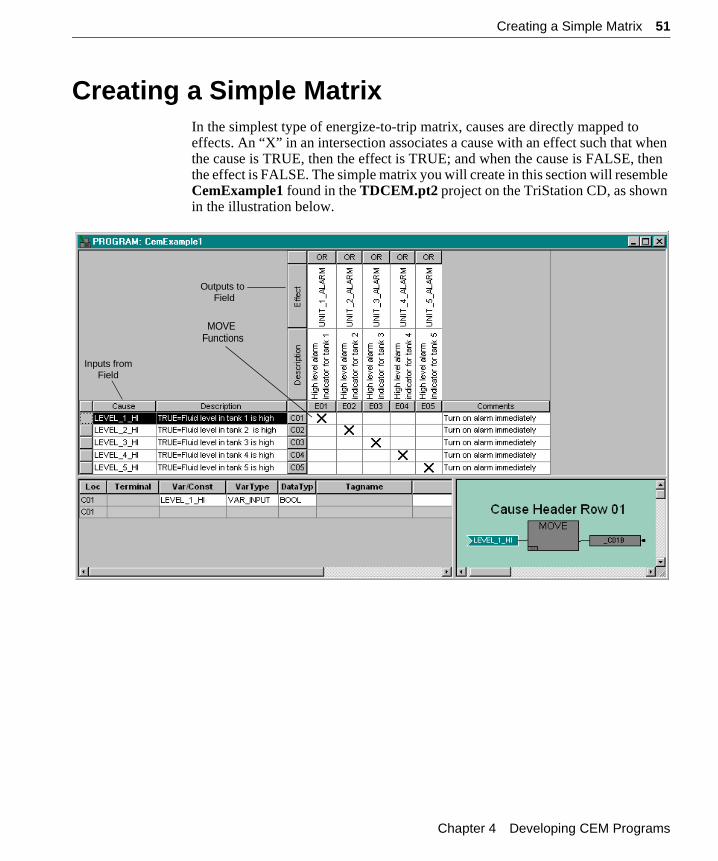
Creating a Simple MatrixIn the simplest type of energize-to-trip matrix, causes are directly mapped to effects. An “X” in an intersection associates a cause with an effect such that when the cause is TRUE, then the effect is TRUE; and when the cause is FALSE, then the effect is FALSE. The simple matrix you will create in this section will resemble CemExample1 found in the TDCEM.pt2 project on the TriStation CD, as shown in the illustration below.
MOVE
Inputs fromField
Functions
Outputs toField
Chapter 4 Developing CEM Programs
52 Creating a Simple Matrix
Steps to Follow
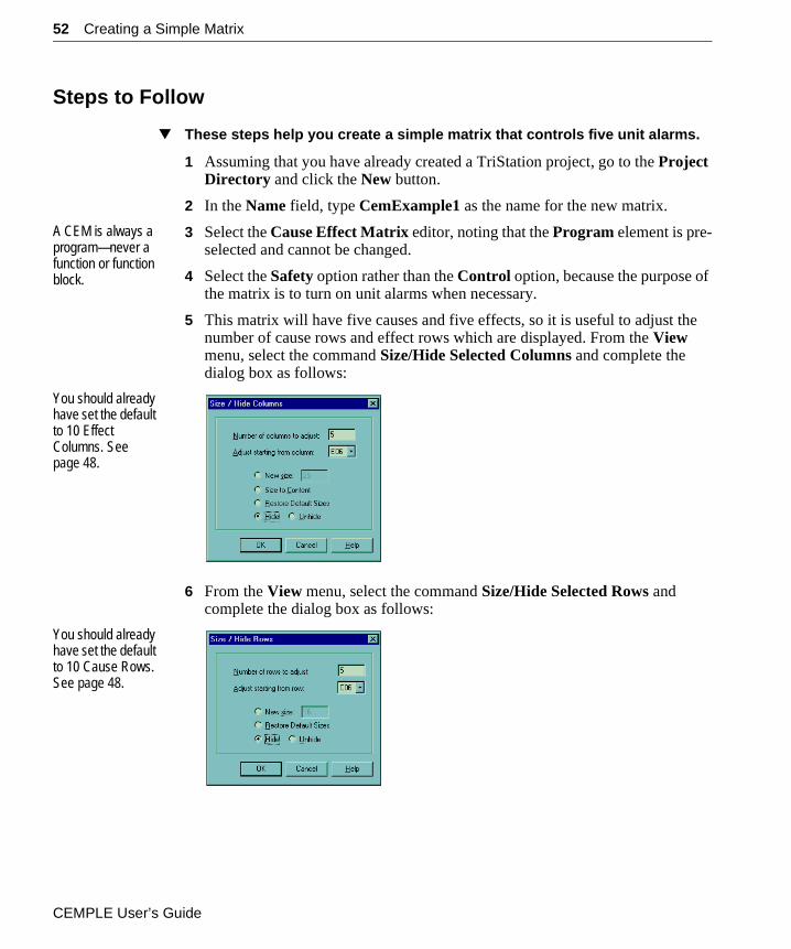
▼ These steps help you create a simple matrix that controls five unit alarms.
1 Assuming that you have already created a TriStation project, go to the Project Directory and click the New button.
2 In the Name field, type CemExample1 as the name for the new matrix.
A CEM is always a program—never a function or function block.
3 Select the Cause Effect Matrix editor, noting that the Program element is pre-selected and cannot be changed.
4 Select the Safety option rather than the Control option, because the purpose of the matrix is to turn on unit alarms when necessary.
5 This matrix will have five causes and five effects, so it is useful to adjust the number of cause rows and effect rows which are displayed. From the View menu, select the command Size/Hide Selected Columns and complete the dialog box as follows:
You should already have set the default to 10 Effect Columns. See page 48.
6 From the View menu, select the command Size/Hide Selected Rows and complete the dialog box as follows:
You should already have set the default to 10 Cause Rows. See page 48.
CEMPLE User’s Guide
Creating a Simple Matrix 53
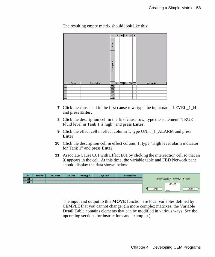
The resulting empty matrix should look like this:
7 Click the cause cell in the first cause row, type the input name LEVEL_1_HI and press Enter.
8 Click the description cell in the first cause row, type the statement “TRUE = Fluid level in Tank 1 is high” and press Enter.
9 Click the effect cell in effect column 1, type UNIT_1_ALARM and press Enter.
10 Click the description cell in effect column 1, type “High level alarm indicator for Tank 1” and press Enter.
11 Associate Cause C01 with Effect E01 by clicking the intersection cell so that an X appears in the cell. At this time, the variable table and FBD Network pane should display the data shown below:
The input and output to this MOVE function are local variables defined by CEMPLE that you cannot change. (In more complex matrixes, the Variable Detail Table contains elements that can be modified in various ways. See the upcoming sections for instructions and examples.)
Chapter 4 Developing CEM Programs
54 Creating a Simple Matrix
12 Repeat steps 7 through 11 for Cause Rows 2 through 5 and Effect Columns 2 though 5. When you are finished, the matrix should look like the one shown at the beginning of this section.
13 Select the Build command from the Element menu. If you have followed the above instructions correctly, the message bar will say there are no errors and no warnings. If you do have errors, double-click on the error message to find the error location.
CEMPLE User’s Guide
Creating a Matrix with Intersection Functions 55
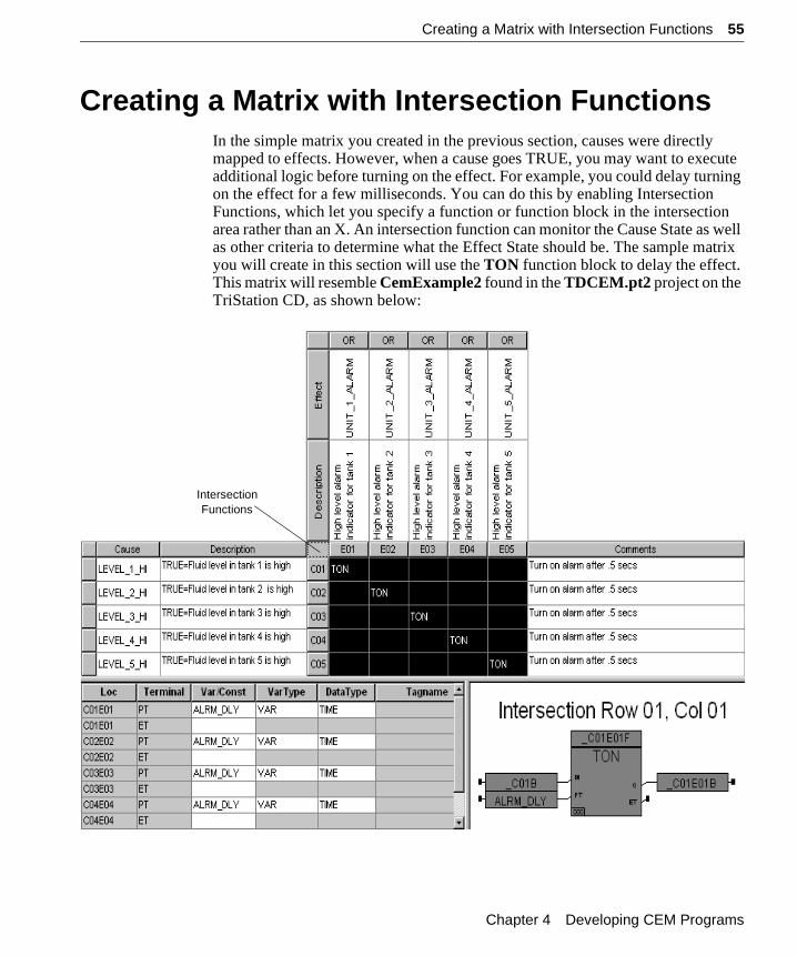
Creating a Matrix with Intersection FunctionsIn the simple matrix you created in the previous section, causes were directly mapped to effects. However, when a cause goes TRUE, you may want to execute additional logic before turning on the effect. For example, you could delay turning on the effect for a few milliseconds. You can do this by enabling Intersection Functions, which let you specify a function or function block in the intersection area rather than an X. An intersection function can monitor the Cause State as well as other criteria to determine what the Effect State should be. The sample matrix you will create in this section will use the TON function block to delay the effect. This matrix will resemble CemExample2 found in the TDCEM.pt2 project on the TriStation CD, as shown below:
IntersectionFunctions
Chapter 4 Developing CEM Programs
56 Creating a Matrix with Intersection Functions
Steps to Follow
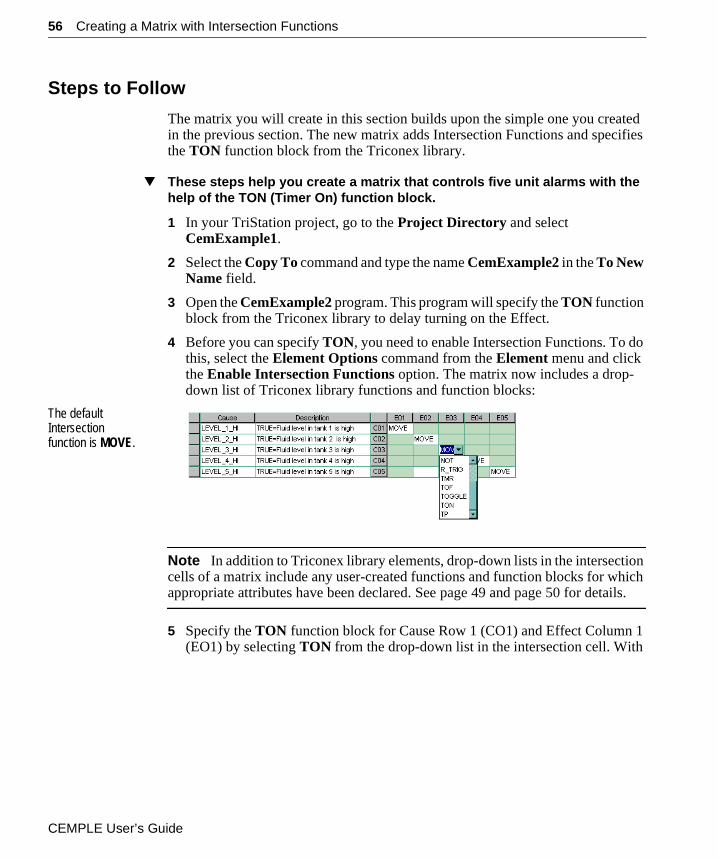
The matrix you will create in this section builds upon the simple one you created in the previous section. The new matrix adds Intersection Functions and specifies the TON function block from the Triconex library.
▼ These steps help you create a matrix that controls five unit alarms with the help of the TON (Timer On) function block.
1 In your TriStation project, go to the Project Directory and select CemExample1.
2 Select the Copy To command and type the name CemExample2 in the To New Name field.
3 Open the CemExample2 program. This program will specify the TON function block from the Triconex library to delay turning on the Effect.
4 Before you can specify TON, you need to enable Intersection Functions. To do this, select the Element Options command from the Element menu and click the Enable Intersection Functions option. The matrix now includes a drop-down list of Triconex library functions and function blocks:
The default Intersection function is MOVE.
Note In addition to Triconex library elements, drop-down lists in the intersection cells of a matrix include any user-created functions and function blocks for which appropriate attributes have been declared. See page 49 and page 50 for details.
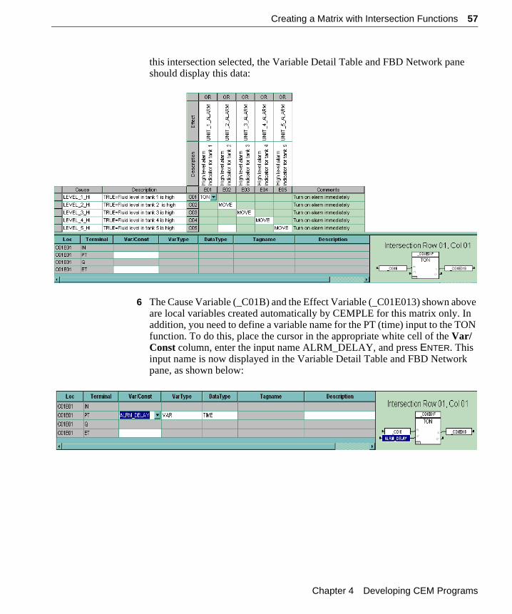
5 Specify the TON function block for Cause Row 1 (CO1) and Effect Column 1 (EO1) by selecting TON from the drop-down list in the intersection cell. With
CEMPLE User’s Guide
Creating a Matrix with Intersection Functions 57
this intersection selected, the Variable Detail Table and FBD Network pane should display this data:
6 The Cause Variable (_C01B) and the Effect Variable (_C01E013) shown above are local variables created automatically by CEMPLE for this matrix only. In addition, you need to define a variable name for the PT (time) input to the TON function. To do this, place the cursor in the appropriate white cell of the Var/Const column, enter the input name ALRM_DELAY, and press ENTER. This input name is now displayed in the Variable Detail Table and FBD Network pane, as shown below:
Chapter 4 Developing CEM Programs
58 Creating a Matrix with Intersection Functions
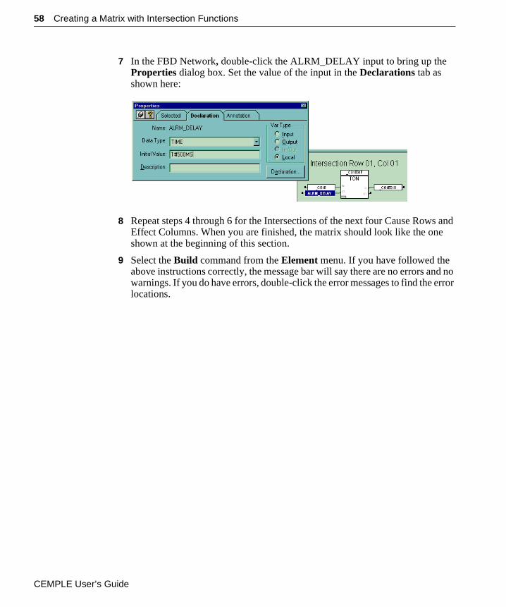
7 In the FBD Network, double-click the ALRM_DELAY input to bring up the Properties dialog box. Set the value of the input in the Declarations tab as shown here:
8 Repeat steps 4 through 6 for the Intersections of the next four Cause Rows and Effect Columns. When you are finished, the matrix should look like the one shown at the beginning of this section.
9 Select the Build command from the Element menu. If you have followed the above instructions correctly, the message bar will say there are no errors and no warnings. If you do have errors, double-click the error messages to find the error locations.
CEMPLE User’s Guide
Creating a Matrix with Cause Header Functions 59
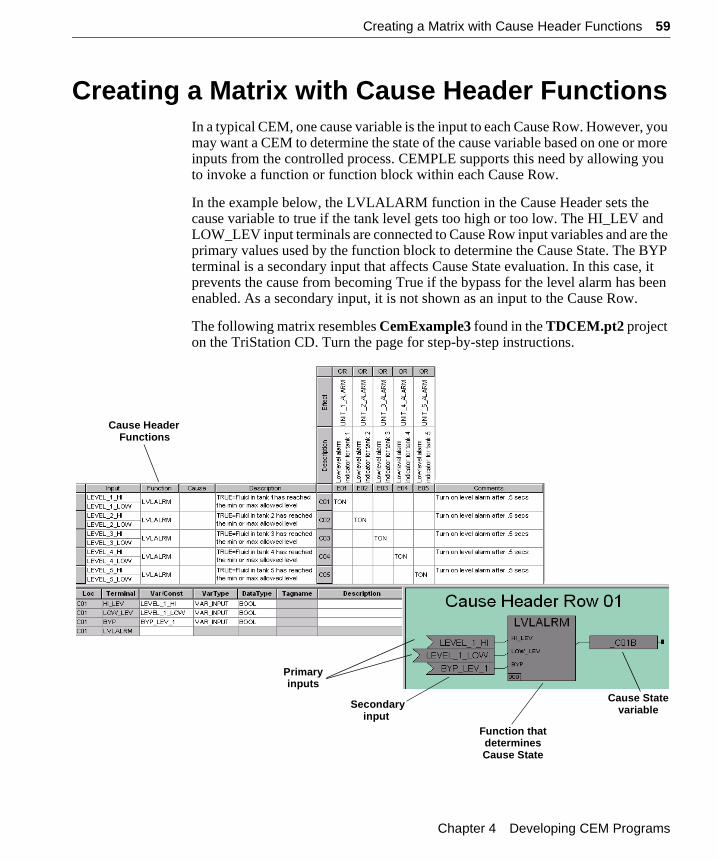
Creating a Matrix with Cause Header FunctionsIn a typical CEM, one cause variable is the input to each Cause Row. However, you may want a CEM to determine the state of the cause variable based on one or more inputs from the controlled process. CEMPLE supports this need by allowing you to invoke a function or function block within each Cause Row.
In the example below, the LVLALARM function in the Cause Header sets the cause variable to true if the tank level gets too high or too low. The HI_LEV and LOW_LEV input terminals are connected to Cause Row input variables and are the primary values used by the function block to determine the Cause State. The BYP terminal is a secondary input that affects Cause State evaluation. In this case, it prevents the cause from becoming True if the bypass for the level alarm has been enabled. As a secondary input, it is not shown as an input to the Cause Row.
The following matrix resembles CemExample3 found in the TDCEM.pt2 project on the TriStation CD. Turn the page for step-by-step instructions.
Cause HeaderFunctions
Primary
Function thatdeterminesCause State
Cause Statevariable
inputs
Secondaryinput
Chapter 4 Developing CEM Programs
60 Creating a Matrix with Cause Header Functions
Steps to Follow
The matrix you will create here builds upon the one you created in the previous section, which included Intersection Functions. The new matrix will add Cause Header Functions and specify the LVLALARM function you created earlier.
▼ These steps help you create a matrix that controls five unit alarms with the help of the TON library function block and the user-defined LVLALRM function, which allows two inputs to each Cause Row.
1 In your TriStation project, go to the Project Directory and select CemExample2.
2 Select the Copy To command and type the name CemExample3 in the To New Name field.
3 Open the CemExample3 program.
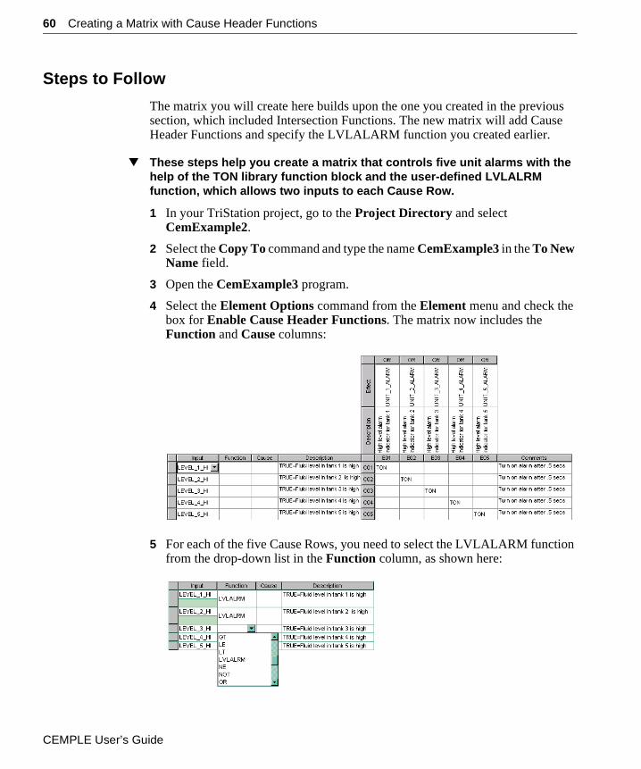
4 Select the Element Options command from the Element menu and check the box for Enable Cause Header Functions. The matrix now includes the Function and Cause columns:
5 For each of the five Cause Rows, you need to select the LVLALARM function from the drop-down list in the Function column, as shown here:
CEMPLE User’s Guide
Creating a Matrix with Cause Header Functions 61
LVLALRM is available for selection in the Function column of the Cause Header because you declared the appropriate attributes when you created the function, enabling it for use in a Cause Header with two inputs. See “Creating a Function” on page 49 for details.
Note In addition to Triconex library elements, the drop-down list in the Function column of a Cause Header includes any user-created functions and function blocks for which appropriate attributes have been declared. See page 49 and page 50 for details.
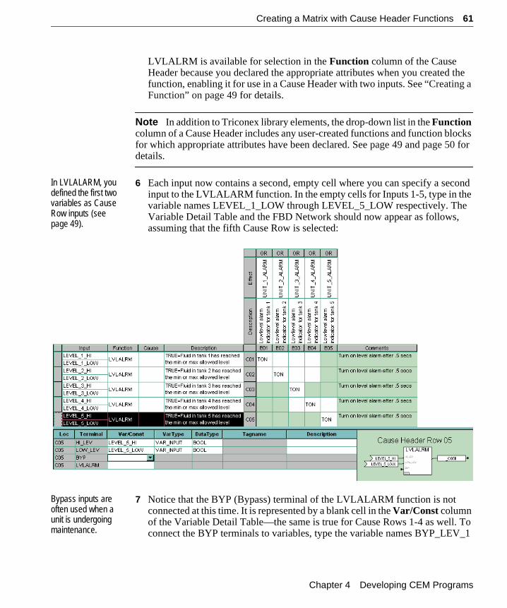
In LVLALARM, you defined the first two variables as Cause Row inputs (see page 49).
6 Each input now contains a second, empty cell where you can specify a second input to the LVLALARM function. In the empty cells for Inputs 1-5, type in the variable names LEVEL_1_LOW through LEVEL_5_LOW respectively. The Variable Detail Table and the FBD Network should now appear as follows, assuming that the fifth Cause Row is selected:
Bypass inputs are often used when a unit is undergoing maintenance.
7 Notice that the BYP (Bypass) terminal of the LVLALARM function is not connected at this time. It is represented by a blank cell in the Var/Const column of the Variable Detail Table—the same is true for Cause Rows 1-4 as well. To connect the BYP terminals to variables, type the variable names BYP_LEV_1
Chapter 4 Developing CEM Programs
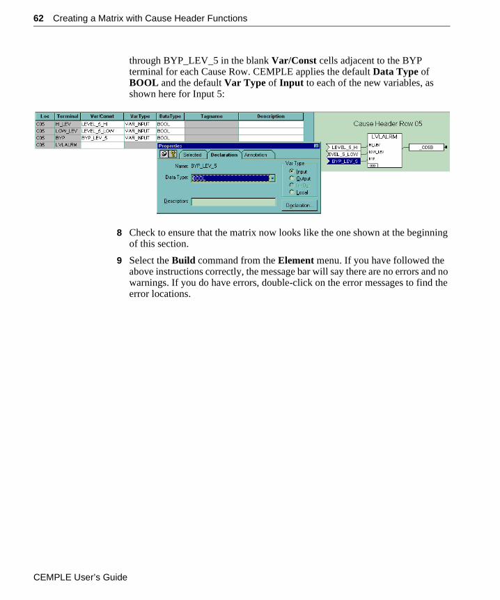
62 Creating a Matrix with Cause Header Functions
through BYP_LEV_5 in the blank Var/Const cells adjacent to the BYP terminal for each Cause Row. CEMPLE applies the default Data Type of BOOL and the default Var Type of Input to each of the new variables, as shown here for Input 5:
8 Check to ensure that the matrix now looks like the one shown at the beginning of this section.
9 Select the Build command from the Element menu. If you have followed the above instructions correctly, the message bar will say there are no errors and no warnings. If you do have errors, double-click on the error messages to find the error locations.
CEMPLE User’s Guide
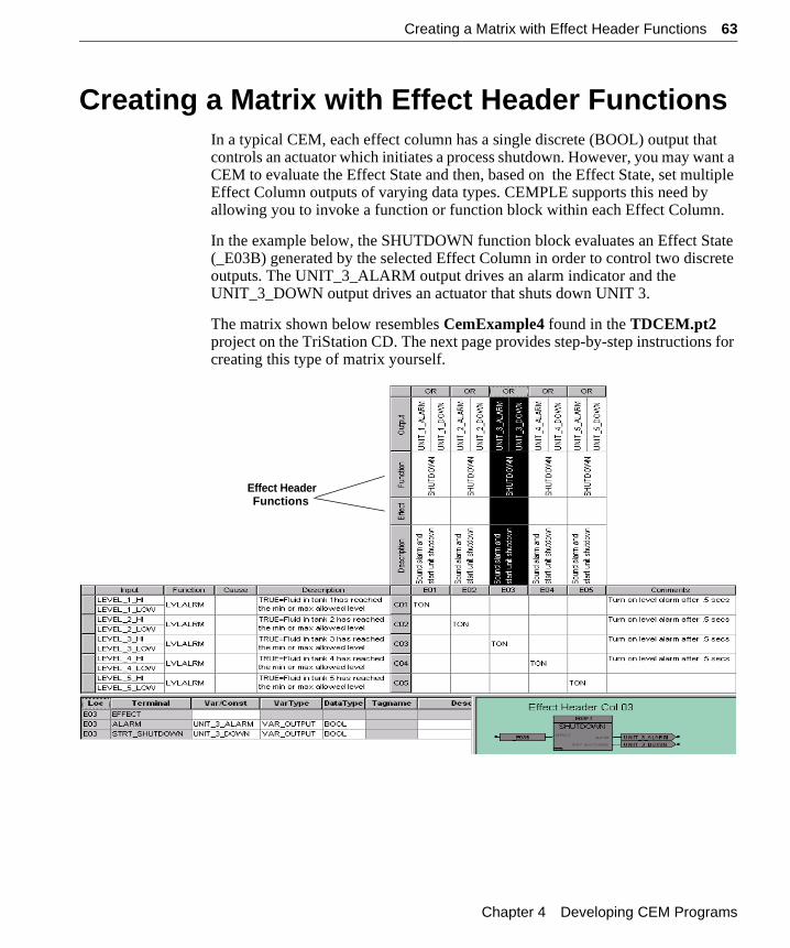
Creating a Matrix with Effect Header Functions 63
Creating a Matrix with Effect Header FunctionsIn a typical CEM, each effect column has a single discrete (BOOL) output that controls an actuator which initiates a process shutdown. However, you may want a CEM to evaluate the Effect State and then, based on the Effect State, set multiple Effect Column outputs of varying data types. CEMPLE supports this need by allowing you to invoke a function or function block within each Effect Column.
In the example below, the SHUTDOWN function block evaluates an Effect State (_E03B) generated by the selected Effect Column in order to control two discrete outputs. The UNIT_3_ALARM output drives an alarm indicator and the UNIT_3_DOWN output drives an actuator that shuts down UNIT 3.
The matrix shown below resembles CemExample4 found in the TDCEM.pt2 project on the TriStation CD. The next page provides step-by-step instructions for creating this type of matrix yourself.
Effect HeaderFunctions
Chapter 4 Developing CEM Programs
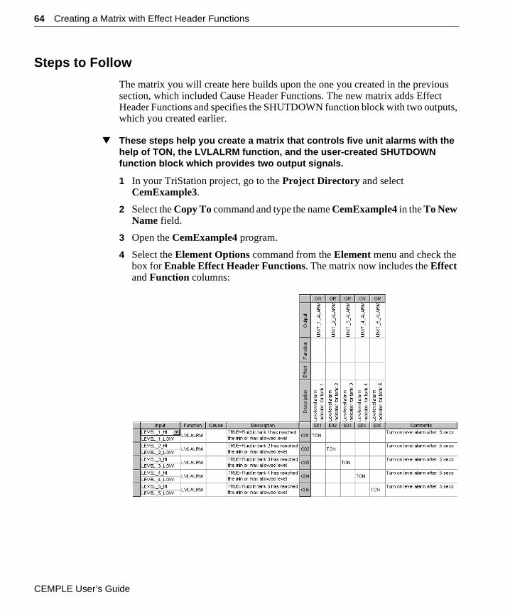
64 Creating a Matrix with Effect Header Functions
Steps to Follow
The matrix you will create here builds upon the one you created in the previous section, which included Cause Header Functions. The new matrix adds Effect Header Functions and specifies the SHUTDOWN function block with two outputs, which you created earlier.
▼ These steps help you create a matrix that controls five unit alarms with the help of TON, the LVLALRM function, and the user-created SHUTDOWN function block which provides two output signals.
1 In your TriStation project, go to the Project Directory and select CemExample3.
2 Select the Copy To command and type the name CemExample4 in the To New Name field.
3 Open the CemExample4 program.
4 Select the Element Options command from the Element menu and check the box for Enable Effect Header Functions. The matrix now includes the Effect and Function columns:
CEMPLE User’s Guide
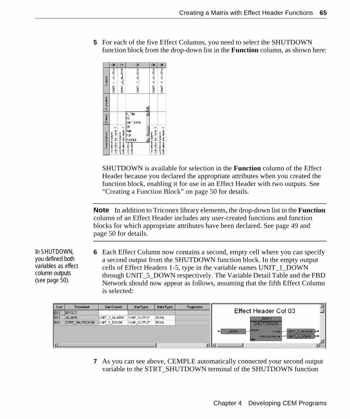
Creating a Matrix with Effect Header Functions 65
5 For each of the five Effect Columns, you need to select the SHUTDOWN function block from the drop-down list in the Function column, as shown here:
SHUTDOWN is available for selection in the Function column of the Effect Header because you declared the appropriate attributes when you created the function block, enabling it for use in an Effect Header with two outputs. See “Creating a Function Block” on page 50 for details.
Note In addition to Triconex library elements, the drop-down list in the Function column of an Effect Header includes any user-created functions and function blocks for which appropriate attributes have been declared. See page 49 and page 50 for details.
In SHUTDOWN, you defined both variables as effect column outputs (see page 50).
6 Each Effect Column now contains a second, empty cell where you can specify a second output from the SHUTDOWN function block. In the empty output cells of Effect Headers 1-5, type in the variable names UNIT_1_DOWN through UNIT_5_DOWN respectively. The Variable Detail Table and the FBD Network should now appear as follows, assuming that the fifth Effect Column is selected:
7 As you can see above, CEMPLE automatically connected your second output variable to the STRT_SHUTDOWN terminal of the SHUTDOWN function
Chapter 4 Developing CEM Programs
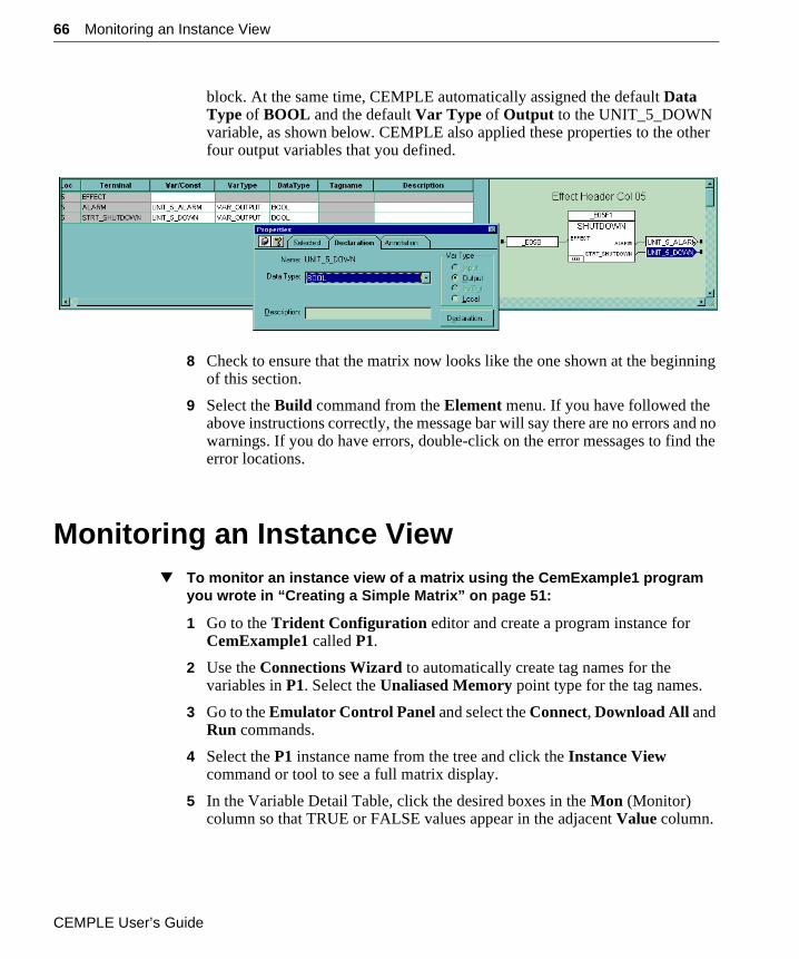
66 Monitoring an Instance View
block. At the same time, CEMPLE automatically assigned the default Data Type of BOOL and the default Var Type of Output to the UNIT_5_DOWN variable, as shown below. CEMPLE also applied these properties to the other four output variables that you defined.
8 Check to ensure that the matrix now looks like the one shown at the beginning of this section.
9 Select the Build command from the Element menu. If you have followed the above instructions correctly, the message bar will say there are no errors and no warnings. If you do have errors, double-click on the error messages to find the error locations.
Monitoring an Instance View▼ To monitor an instance view of a matrix using the CemExample1 program
you wrote in “Creating a Simple Matrix” on page 51:
1 Go to the Trident Configuration editor and create a program instance for CemExample1 called P1.
2 Use the Connections Wizard to automatically create tag names for the variables in P1. Select the Unaliased Memory point type for the tag names.
3 Go to the Emulator Control Panel and select the Connect, Download All and Run commands.
4 Select the P1 instance name from the tree and click the Instance View command or tool to see a full matrix display.
5 In the Variable Detail Table, click the desired boxes in the Mon (Monitor) column so that TRUE or FALSE values appear in the adjacent Value column.
CEMPLE User’s Guide
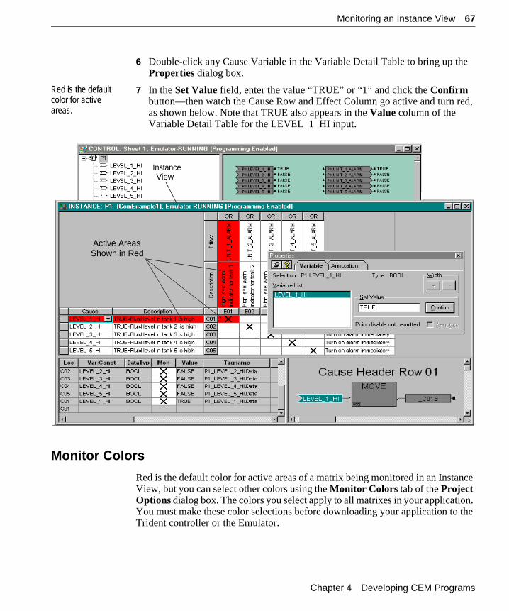
Monitoring an Instance View 67
6 Double-click any Cause Variable in the Variable Detail Table to bring up the Properties dialog box.
Red is the default color for active areas.
7 In the Set Value field, enter the value “TRUE” or “1” and click the Confirm button—then watch the Cause Row and Effect Column go active and turn red, as shown below. Note that TRUE also appears in the Value column of the Variable Detail Table for the LEVEL_1_HI input.
Monitor Colors
Red is the default color for active areas of a matrix being monitored in an Instance View, but you can select other colors using the Monitor Colors tab of the Project Options dialog box. The colors you select apply to all matrixes in your application. You must make these color selections before downloading your application to the Trident controller or the Emulator.
InstanceView
Active AreasShown in Red
Chapter 4 Developing CEM Programs
68 Monitoring an Instance View
Note See the Developer’s Guide for Trident Systems for details about the control panels and enabling/disabling of variables.
CEMPLE User’s Guide
C H A P T E R 5
Advanced Techniques andAccessory Features
This chapter describes the following advanced techniques for power programming of complex CEMs:
“Designing CEM Functions & Function Blocks” . . . . . . . . . . . . . . . 70
“Sharing Cause States & Effect States” . . . . . . . . . . . . . . . . . . . . . . 78
The chapter also describes a few accessory features for added convenience:
“Using the View Manager” . . . . . . . . . . . . . . . . . . . . . . . . . . . . . . . . 81
“Viewing Intermediate FBD & ST Code” . . . . . . . . . . . . . . . . . . . . 82
“Printing Variable Location Lists” . . . . . . . . . . . . . . . . . . . . . . . . . . 83
CEMPLE User’s Guide
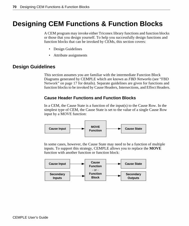
70 Designing CEM Functions & Function Blocks
Designing CEM Functions & Function BlocksA CEM program may invoke either Triconex library functions and function blocks or those that you design yourself. To help you successfully design functions and function blocks that can be invoked by CEMs, this section covers:
• Design Guidelines
• Attribute assignments
Design Guidelines
This section assumes you are familiar with the intermediate Function Block Diagrams generated by CEMPLE which are known as FBD Networks (see “FBD Network” on page 17 for details). Separate guidelines are given for functions and function blocks to be invoked by Cause Headers, Intersections, and Effect Headers.
Cause Header Functions and Function Blocks
In a CEM, the Cause State is a function of the input(s) to the Cause Row. In the simplest type of CEM, the Cause State is set to the value of a single Cause Row input by a MOVE function:
In some cases, however, the Cause State may need to be a function of multiple inputs. To support this strategy, CEMPLE allows you to replace the MOVE function with another function or function block:
Cause InputMOVE
FunctionCause State
Cause Input CauseFunction
- or -Function
Block
Cause State
SecondaryInputs
SecondaryOutputs
CEMPLE User’s Guide
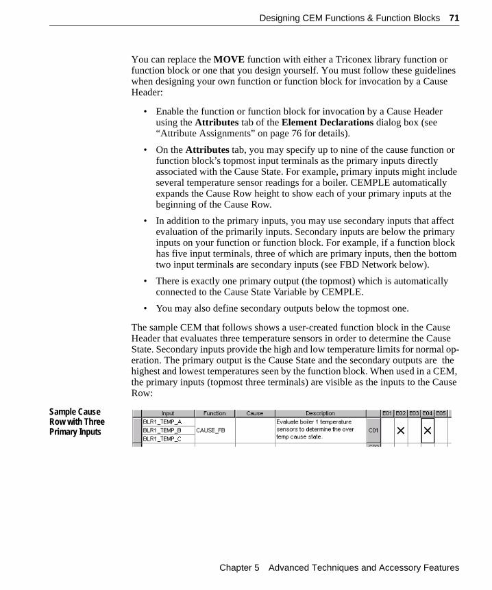
Designing CEM Functions & Function Blocks 71
You can replace the MOVE function with either a Triconex library function or function block or one that you design yourself. You must follow these guidelines when designing your own function or function block for invocation by a Cause Header:
• Enable the function or function block for invocation by a Cause Header using the Attributes tab of the Element Declarations dialog box (see “Attribute Assignments” on page 76 for details).
• On the Attributes tab, you may specify up to nine of the cause function or function block’s topmost input terminals as the primary inputs directly associated with the Cause State. For example, primary inputs might include several temperature sensor readings for a boiler. CEMPLE automatically expands the Cause Row height to show each of your primary inputs at the beginning of the Cause Row.
• In addition to the primary inputs, you may use secondary inputs that affect evaluation of the primarily inputs. Secondary inputs are below the primary inputs on your function or function block. For example, if a function block has five input terminals, three of which are primary inputs, then the bottom two input terminals are secondary inputs (see FBD Network below).
• There is exactly one primary output (the topmost) which is automatically connected to the Cause State Variable by CEMPLE.
• You may also define secondary outputs below the topmost one.
The sample CEM that follows shows a user-created function block in the Cause Header that evaluates three temperature sensors in order to determine the Cause State. Secondary inputs provide the high and low temperature limits for normal op-eration. The primary output is the Cause State and the secondary outputs are the highest and lowest temperatures seen by the function block. When used in a CEM, the primary inputs (topmost three terminals) are visible as the inputs to the Cause Row:
Sample Cause Row with Three Primary Inputs
Chapter 5 Advanced Techniques and Accessory Features
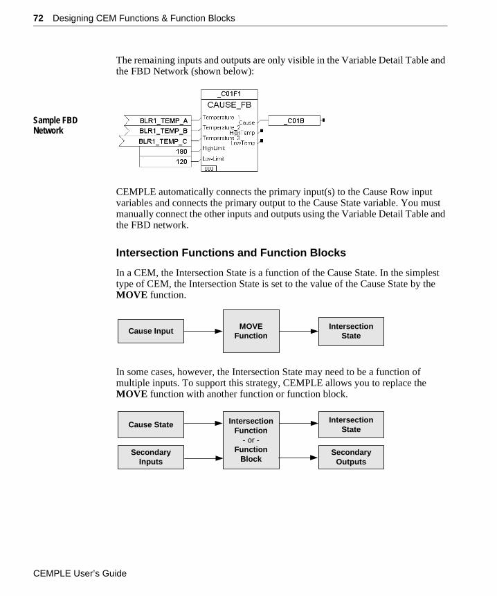
72 Designing CEM Functions & Function Blocks
The remaining inputs and outputs are only visible in the Variable Detail Table and the FBD Network (shown below):
Sample FBD Network
CEMPLE automatically connects the primary input(s) to the Cause Row input variables and connects the primary output to the Cause State variable. You must manually connect the other inputs and outputs using the Variable Detail Table and the FBD network.
Intersection Functions and Function Blocks
In a CEM, the Intersection State is a function of the Cause State. In the simplest type of CEM, the Intersection State is set to the value of the Cause State by the MOVE function.
In some cases, however, the Intersection State may need to be a function of multiple inputs. To support this strategy, CEMPLE allows you to replace the MOVE function with another function or function block.
Cause Input MOVEFunction
IntersectionState
Cause State IntersectionFunction
- or -Function
Block
IntersectionState
SecondaryInputs
SecondaryOutputs
CEMPLE User’s Guide
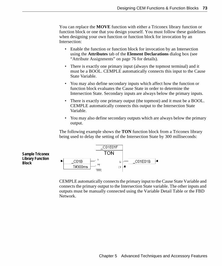
Designing CEM Functions & Function Blocks 73
You can replace the MOVE function with either a Triconex library function or function block or one that you design yourself. You must follow these guidelines when designing your own function or function block for invocation by an Intersection:
• Enable the function or function block for invocation by an Intersection using the Attributes tab of the Element Declarations dialog box (see “Attribute Assignments” on page 76 for details).
• There is exactly one primary input (always the topmost terminal) and it must be a BOOL. CEMPLE automatically connects this input to the Cause State Variable.
• You may also define secondary inputs which affect how the function or function block evaluates the Cause State in order to determine the Intersection State. Secondary inputs are always below the primary inputs.
• There is exactly one primary output (the topmost) and it must be a BOOL. CEMPLE automatically connects this output to the Intersection State Variable.
• You may also define secondary outputs which are always below the primary output.
The following example shows the TON function block from a Triconex library being used to delay the setting of the Intersection State by 300 milliseconds:
Sample Triconex Library Function Block
CEMPLE automatically connects the primary input to the Cause State Variable and connects the primary output to the Intersection State variable. The other inputs and outputs must be manually connected using the Variable Detail Table or the FBD Network.
Chapter 5 Advanced Techniques and Accessory Features
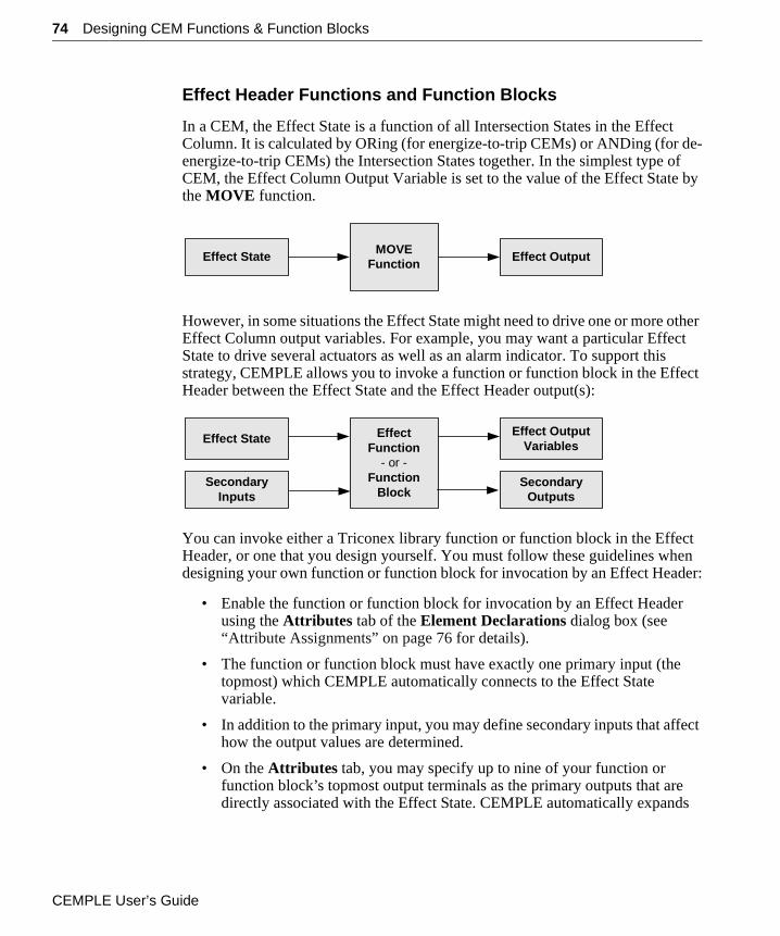
74 Designing CEM Functions & Function Blocks
Effect Header Functions and Function Blocks
In a CEM, the Effect State is a function of all Intersection States in the Effect Column. It is calculated by ORing (for energize-to-trip CEMs) or ANDing (for de-energize-to-trip CEMs) the Intersection States together. In the simplest type of CEM, the Effect Column Output Variable is set to the value of the Effect State by the MOVE function.
However, in some situations the Effect State might need to drive one or more other Effect Column output variables. For example, you may want a particular Effect State to drive several actuators as well as an alarm indicator. To support this strategy, CEMPLE allows you to invoke a function or function block in the Effect Header between the Effect State and the Effect Header output(s):
You can invoke either a Triconex library function or function block in the Effect Header, or one that you design yourself. You must follow these guidelines when designing your own function or function block for invocation by an Effect Header:
• Enable the function or function block for invocation by an Effect Header using the Attributes tab of the Element Declarations dialog box (see “Attribute Assignments” on page 76 for details).
• The function or function block must have exactly one primary input (the topmost) which CEMPLE automatically connects to the Effect State variable.
• In addition to the primary input, you may define secondary inputs that affect how the output values are determined.
• On the Attributes tab, you may specify up to nine of your function or function block’s topmost output terminals as the primary outputs that are directly associated with the Effect State. CEMPLE automatically expands
Effect State MOVEFunction
Effect Output
Effect State EffectFunction
- or -Function
Block
Effect OutputVariables
SecondaryInputs
SecondaryOutputs
CEMPLE User’s Guide
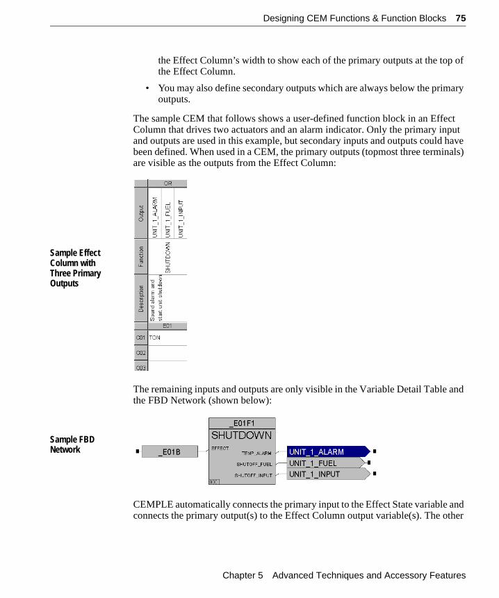
Designing CEM Functions & Function Blocks 75
the Effect Column’s width to show each of the primary outputs at the top of the Effect Column.
• You may also define secondary outputs which are always below the primary outputs.
The sample CEM that follows shows a user-defined function block in an Effect Column that drives two actuators and an alarm indicator. Only the primary input and outputs are used in this example, but secondary inputs and outputs could have been defined. When used in a CEM, the primary outputs (topmost three terminals) are visible as the outputs from the Effect Column:
Sample Effect Column with Three Primary Outputs
The remaining inputs and outputs are only visible in the Variable Detail Table and the FBD Network (shown below):
Sample FBD Network
CEMPLE automatically connects the primary input to the Effect State variable and connects the primary output(s) to the Effect Column output variable(s). The other
Chapter 5 Advanced Techniques and Accessory Features
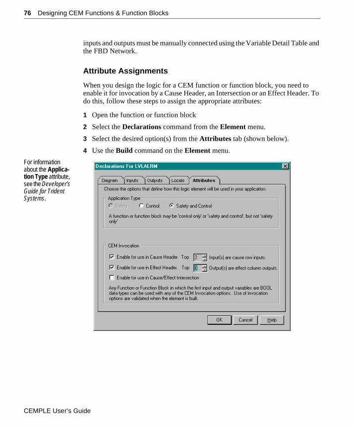
76 Designing CEM Functions & Function Blocks
inputs and outputs must be manually connected using the Variable Detail Table and the FBD Network.
Attribute Assignments
When you design the logic for a CEM function or function block, you need to enable it for invocation by a Cause Header, an Intersection or an Effect Header. To do this, follow these steps to assign the appropriate attributes:
1 Open the function or function block
2 Select the Declarations command from the Element menu.
3 Select the desired option(s) from the Attributes tab (shown below).
4 Use the Build command on the Element menu.
For information about the Applica-tion Type attribute, see the Developer’s Guide for Trident Systems.
CEMPLE User’s Guide
Designing CEM Functions & Function Blocks 77
Number of Inputs
For a function or function block, the Attributes dialog box lets you define how many of its topmost input variables will serve as primary inputs to the Cause Row, which are directly associated with the Cause State. Secondary inputs may also exist, such as timers or counter presets—these affect the manner in which the Cause State is evaluated.
Number of Outputs
For a function or function block, the Attributes dialog box lets you define how many of its topmost output variables will serve as Effect Column outputs, which are calculated using the Effect State. Secondary outputs may also exist, such as variables for elapsed time or current count.
Chapter 5 Advanced Techniques and Accessory Features
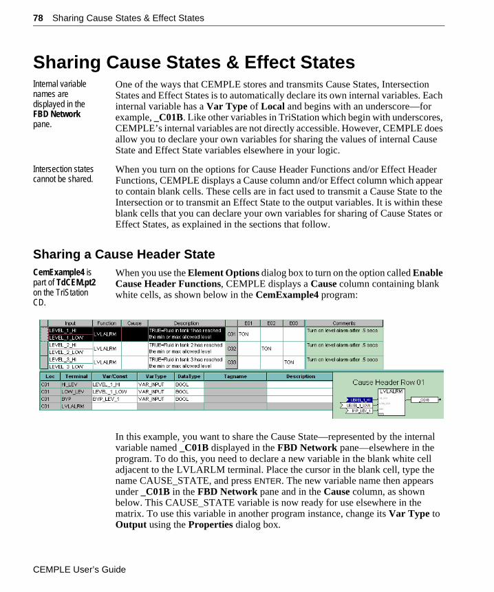
78 Sharing Cause States & Effect States
Sharing Cause States & Effect StatesInternal variable names are displayed in the FBD Network pane.
One of the ways that CEMPLE stores and transmits Cause States, Intersection States and Effect States is to automatically declare its own internal variables. Each internal variable has a Var Type of Local and begins with an underscore—for example, _C01B. Like other variables in TriStation which begin with underscores, CEMPLE’s internal variables are not directly accessible. However, CEMPLE does allow you to declare your own variables for sharing the values of internal Cause State and Effect State variables elsewhere in your logic.
Intersection states cannot be shared.
When you turn on the options for Cause Header Functions and/or Effect Header Functions, CEMPLE displays a Cause column and/or Effect column which appear to contain blank cells. These cells are in fact used to transmit a Cause State to the Intersection or to transmit an Effect State to the output variables. It is within these blank cells that you can declare your own variables for sharing of Cause States or Effect States, as explained in the sections that follow.
Sharing a Cause Header StateCemExample4 is part of TdCEM.pt2 on the TriStation CD.
When you use the Element Options dialog box to turn on the option called Enable Cause Header Functions, CEMPLE displays a Cause column containing blank white cells, as shown below in the CemExample4 program:
In this example, you want to share the Cause State—represented by the internal variable named _C01B displayed in the FBD Network pane—elsewhere in the program. To do this, you need to declare a new variable in the blank white cell adjacent to the LVLARLM terminal. Place the cursor in the blank cell, type the name CAUSE_STATE, and press ENTER. The new variable name then appears under _C01B in the FBD Network pane and in the Cause column, as shown below. This CAUSE_STATE variable is now ready for use elsewhere in the matrix. To use this variable in another program instance, change its Var Type to Output using the Properties dialog box.
CEMPLE User’s Guide
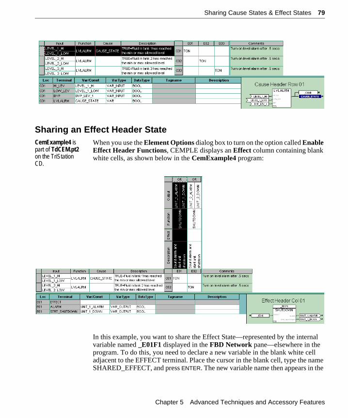
Sharing Cause States & Effect States 79
Sharing an Effect Header StateCemExample4 is part of TdCEM.pt2 on the TriStation CD.
When you use the Element Options dialog box to turn on the option called Enable Effect Header Functions, CEMPLE displays an Effect column containing blank white cells, as shown below in the CemExample4 program:
In this example, you want to share the Effect State—represented by the internal variable named _E01F1 displayed in the FBD Network pane—elsewhere in the program. To do this, you need to declare a new variable in the blank white cell adjacent to the EFFECT terminal. Place the cursor in the blank cell, type the name SHARED_EFFECT, and press ENTER. The new variable name then appears in the
Chapter 5 Advanced Techniques and Accessory Features
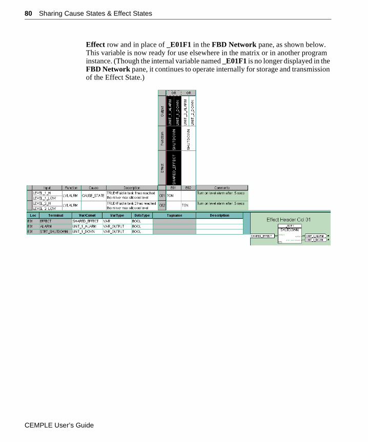
80 Sharing Cause States & Effect States
Effect row and in place of _E01F1 in the FBD Network pane, as shown below. This variable is now ready for use elsewhere in the matrix or in another program instance. (Though the internal variable named _E01F1 is no longer displayed in the FBD Network pane, it continues to operate internally for storage and transmission of the Effect State.)
CEMPLE User’s Guide
Using the View Manager 81
Using the View ManagerThe View Manager dialog box, accessible from the View menu, saves the format of the current matrix view so that it may be recalled later. The format includes:
• Widths of columns
• Heights of rows
• Hidden rows and columns
• Unhidden rows and columns
The View Manager can be helpful when you have a very large matrix that cannot be displayed on the screen all at one time.
▼ Follow these basic steps to use the View Manager successfully:
1 Format the view you want to save by using:
• Commands on the View menu (described in “Table of CEMPLE Tools” on page 27):
– Zoom
– Size/Hide Selected Columns
– Size/Hide Selected Rows
– Size/Hide Comment Column
– Show All Rows/Columns
– Show Effects for Selected Causes
– Show Causes for Selected Effects
– Hide Effects not for Selected Causes
– Hide Causes not for Selected Effects
• Drag and double-click editing techniques described in “Sizing, Hiding & Unhiding Cells” on page 37
2 Click the Save button, then type a name for the view you will save and click OK.
3 When it is time to recall a particular view, select its name from the View Manager’s list and click the Load button.
Note The View Manager saves the format of the current matrix layout, but does not save variable names or other data which may change.
Chapter 5 Advanced Techniques and Accessory Features
82 Viewing Intermediate FBD & ST Code
Management of Newly Added Cells
When you add new cells to a CEM program using the Insert Rows or Insert Columns command on the Edit menu, the Make visible on all managed views option lets you show or hide the newly added cells in existing views that you have defined with the View Manager dialog box.
Viewing Intermediate FBD & ST CodeThe Element menu provides three related commands for CEMPLE users:
• Build
• Intermediate FBD Code
• Intermediate ST Code
When you use the Build command to compile a CEM, TriStation automatically generates an FBD program which you can view in read-only form by selecting the Intermediate FBD Code command. You can also view the ST source code underlying the FBD program by selecting the Intermediate ST Code command.
The read-only intermediate code can be used for:
• Debugging purposes
• Understanding how CEMs are evaluated
– For more information, see “Evaluation of CEM Programs” on page 21
• Viewing the OR or AND functions which are used in CEM evaluation but are not displayed in the FBD Network pane
Use the Print command on the File menu.
• Printing the networks generated by a CEM
Note The only printable portion of a CEM is the matrix—neither the FBD Network pane nor the Variable Detail Table can be printed.
CEMPLE User’s Guide
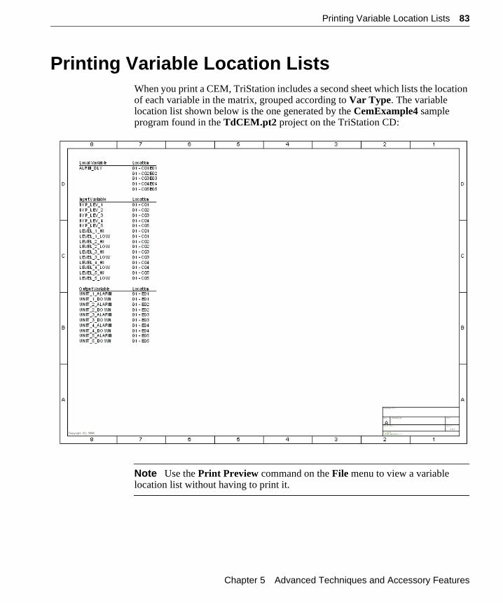
Printing Variable Location Lists 83
Printing Variable Location ListsWhen you print a CEM, TriStation includes a second sheet which lists the location of each variable in the matrix, grouped according to Var Type. The variable location list shown below is the one generated by the CemExample4 sample program found in the TdCEM.pt2 project on the TriStation CD:
Note Use the Print Preview command on the File menu to view a variable location list without having to print it.
Chapter 5 Advanced Techniques and Accessory Features

84 Printing Variable Location Lists
CEMPLE User’s Guide
A P P E N D I X A
CEM-Specific Error Messages
This appendix lists only the CEM-specific error messages that TriStation may generate. See the TriStation Help System for explanations of other error messages.
Note In the descriptions below, nnnn is used as a placeholder for any matrix location; Cnnn is used for any cause; and Ennn is used for any effect.
CE0001 There are no defined intersections for cause Cnnn
Cause: There are no defined intersections for the specified cause.
Solution: Define an intersection for the cause.
CE0002 Intersections defined for undefined cause Cnnn
Cause: Intersections are defined for a cause which has not yet been defined.
Solution: Define a cause for the already-defined intersections.
CE0003 There are no defined intersections for effect Ennn
Cause: No intersections are defined for the specified effect.
Solution: Define an intersection for the effect.
CE0004 Intersections defined for undefined effect Ennn
Cause: Intersections have been defined for an effect which has not yet been defined.
Solution: Define an effect for the intersections.
CEMPLE User’s Guide
86
CE0005 Out-of-date or invalid function (block) at nnnn
Cause: There is an out-of-date or invalid function or function block at location nnnn in the matrix.
Solution: Update the function or function block at location nnnn.
CE0006 The last row will not be deleted. The CEM must have at least one row at all times.
Cause: Deletion of the only row in the matrix was attempted.
Solution: Ensure that at least one row exists in your matrix at all times.
CE0007 The last column will not be deleted. The CEM must have at least one column at all times.
Cause: Deletion of the only column in the matrix was attempted.
Solution: Ensure that at least one column exists in your matrix at all times.
CE0008 The row limit of 99 has been exceeded. Please specify no more than nn rows to insert.
Cause: Adding the designated number of rows will cause the current matrix to exceed 99 rows.
Solution: Reduce the number of rows being added to ensure that the current matrix will not exceed 99 rows.
CE0009 The column limit of 99 has been exceeded. Please specify no more than nn columns to insert.
Cause: Adding the designated number of columns will cause the current matrix to exceed 99 columns.
Solution: Reduce the number of columns being added to ensure that the current matrix will not exceed 99 columns.
CE0010 Cause Header functions can be disabled only after user-specified functions are removed and after either the input or cause variable is removed when both are defined.
Cause: An attempt was made to disable Cause Header functions either before removing user-created functions, or before removing the Input or Cause Variable when both are defined.
Solution: Remove user-created functions, and the Input or Cause Variable if it is defined. Then disable Cause Header Functions.
CEMPLE User’s Guide
87
CE0011 Effect Header functions can be disabled only after user-specified functions are removed and after either the output or effect variable is removed when both are defined.
Cause: An attempt was made to disable Effect Header functions either before removing user-created functions, or before removing the Output or Cause Variable when both are defined.
Solution: Remove user-created functions, and the Output or Cause Variable if it is defined. Then disable Effect Header functions.
CE0012 Disabling intersection functions will cause all user-defined functions to be changed to “MOVE” functions and all user-defined variables to be removed. Proceed to disable intersection functions?
Cause: An attempt was made to disable Intersection Functions before removing user-created functions or function blocks and variables.
Solution: Make sure that you want to change all user-created functions or function blocks to MOVE functions and remove all user-created variables. Otherwise answer NO.
CE0013 The active intersection limit of 1000 has been exceeded. No more intersections may be made active.
Cause: Your matrix has already reached the limit of 1000 active (non-empty) intersections.
Solution: Decrease the number of intersections that you are actively using, either by deleting the excessive intersections, or by selecting <none> from their drop-down lists.
CE0014 The paste operation may not be performed because the following variables conflict with existing variables: <list of variable names separated by commas>.
Cause: The cells on the clipboard contain variables that have the same names as the cells you’ve selected for the paste, but different data types. You may not change data types with a paste operation.
Solution: Recheck the data you have copied onto the clipboard. If you need to change data types, use the Properties dialog box for each variable.
Appendix A CEM-Specific Error Messages
88
CE0015 The paste may not be performed because selected cells do not match the paste data.
Cause: The type of cells you selected for the paste is incompatible with the paste data on the clipboard. For example, you tried to paste a Cause Row into an Intersection or an Effect Column.
Solution: Make sure that the cells you copy onto the clipboard are the same type as the cells you select for the paste operation. For example, if you copy three Cause Rows onto the clipboard, then select three Cause Rows before using the Paste command.
CE0016 The paste data requires one or more <rows or columns> to be inserted. Select a cell to identify where <rows or columns> should be inserted.
Cause: You have not selected the rows or columns where you would like to paste the data on the clipboard.
Solution: Select appropriate rows or columns that are able to accept the paste data on the clipboard. Make sure that the cells on the clipboard are the same type as the cells you select for the paste.
CE0017 The paste may not be performed because paste data function complexity exceeds that of this document as set in Element Options.
Cause: The paste data on the clipboard is intended for matrix cells that have not yet been defined. These cells could be Cause Headers, Effect Headers or Intersections.
Solution: Use the Element Options command on the Element menu to specify the Cause Headers, Effect Headers or Intersections that are needed to accept the paste data on the clipboard.
CE0018 The paste may not be performed because the maximum active intersection limit of 1000 would be exceeded.
Cause: Pasting the number of intersections on the clipboard would cause the intersection limit of 1000 to be exceeded.
Solution: Reduce the number of intersections on the clipboard to ensure that the current matrix will not exceed 1000 intersections.
CEMPLE User’s Guide
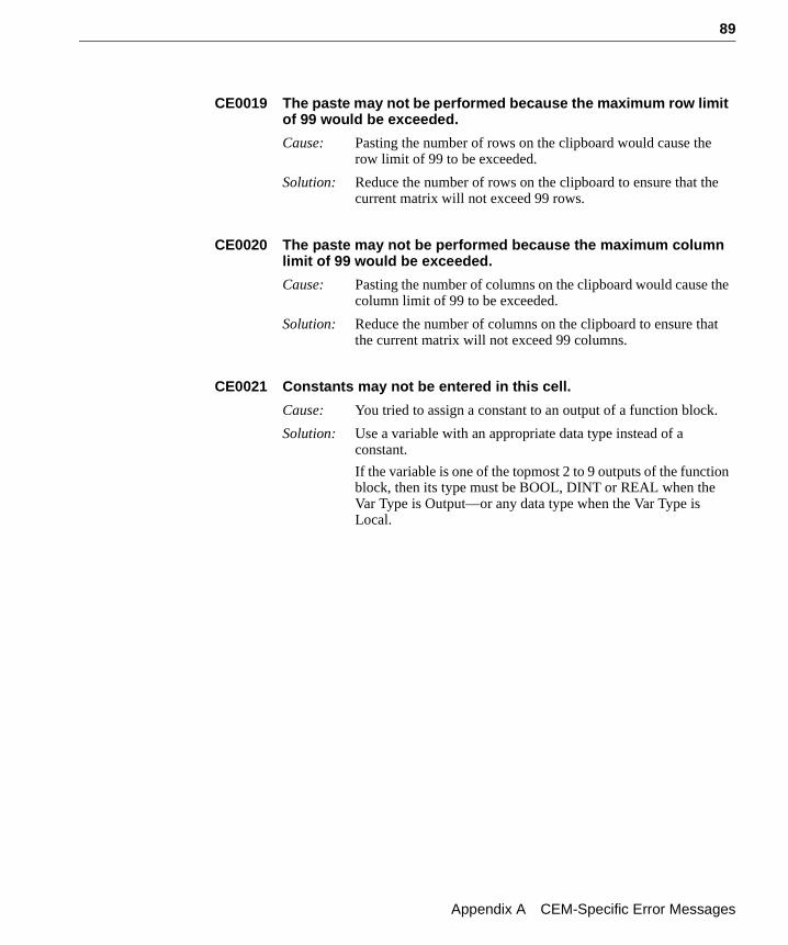
89
CE0019 The paste may not be performed because the maximum row limit of 99 would be exceeded.
Cause: Pasting the number of rows on the clipboard would cause the row limit of 99 to be exceeded.
Solution: Reduce the number of rows on the clipboard to ensure that the current matrix will not exceed 99 rows.
CE0020 The paste may not be performed because the maximum column limit of 99 would be exceeded.
Cause: Pasting the number of columns on the clipboard would cause the column limit of 99 to be exceeded.
Solution: Reduce the number of columns on the clipboard to ensure that the current matrix will not exceed 99 columns.
CE0021 Constants may not be entered in this cell.
Cause: You tried to assign a constant to an output of a function block.
Solution: Use a variable with an appropriate data type instead of a constant.
If the variable is one of the topmost 2 to 9 outputs of the function block, then its type must be BOOL, DINT or REAL when the Var Type is Output—or any data type when the Var Type is Local.
Appendix A CEM-Specific Error Messages

90
CEMPLE User’s Guide
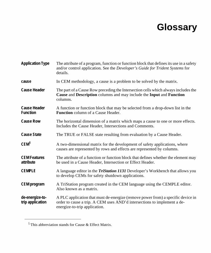
Glossary
Application Type The attribute of a program, function or function block that defines its use in a safety and/or control application. See the Developer’s Guide for Trident Systems for details.
cause In CEM methodology, a cause is a problem to be solved by the matrix.
Cause Header The part of a Cause Row preceding the Intersection cells which always includes the Cause and Description columns and may include the Input and Function columns.
Cause Header Function
A function or function block that may be selected from a drop-down list in the Function column of a Cause Header.
Cause Row The horizontal dimension of a matrix which maps a cause to one or more effects. Includes the Cause Header, Intersections and Comments.
Cause State The TRUE or FALSE state resulting from evaluation by a Cause Header.
CEM1 A two-dimensional matrix for the development of safety applications, where causes are represented by rows and effects are represented by columns.
CEM Features attribute
The attribute of a function or function block that defines whether the element may be used in a Cause Header, Intersection or Effect Header.
CEMPLE A language editor in the TriStation 1131 Developer’s Workbench that allows you to develop CEMs for safety shutdown applications.
CEM program A TriStation program created in the CEM language using the CEMPLE editor. Also known as a matrix.
de-energize-to-trip application
A PLC application that must de-energize (remove power from) a specific device in order to cause a trip. A CEM uses AND’d intersections to implement a de-energize-to-trip application.
1.This abbreviation stands for Cause & Effect Matrix.
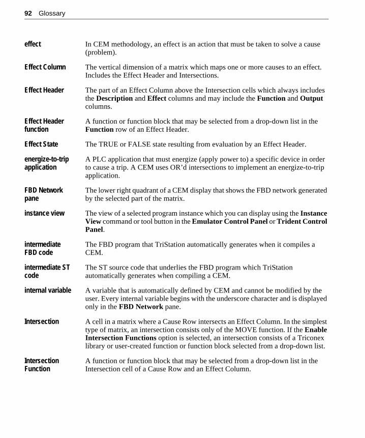
92 Glossary
effect In CEM methodology, an effect is an action that must be taken to solve a cause (problem).
Effect Column The vertical dimension of a matrix which maps one or more causes to an effect. Includes the Effect Header and Intersections.
Effect Header The part of an Effect Column above the Intersection cells which always includes the Description and Effect columns and may include the Function and Output columns.
Effect Header function
A function or function block that may be selected from a drop-down list in the Function row of an Effect Header.
Effect State The TRUE or FALSE state resulting from evaluation by an Effect Header.
energize-to-trip application
A PLC application that must energize (apply power to) a specific device in order to cause a trip. A CEM uses OR’d intersections to implement an energize-to-trip application.
FBD Network pane
The lower right quadrant of a CEM display that shows the FBD network generated by the selected part of the matrix.
instance view The view of a selected program instance which you can display using the Instance View command or tool button in the Emulator Control Panel or Trident Control Panel.
intermediate FBD code
The FBD program that TriStation automatically generates when it compiles a CEM.
intermediate ST code
The ST source code that underlies the FBD program which TriStation automatically generates when compiling a CEM.
internal variable A variable that is automatically defined by CEM and cannot be modified by the user. Every internal variable begins with the underscore character and is displayed only in the FBD Network pane.
Intersection A cell in a matrix where a Cause Row intersects an Effect Column. In the simplest type of matrix, an intersection consists only of the MOVE function. If the Enable Intersection Functions option is selected, an intersection consists of a Triconex library or user-created function or function block selected from a drop-down list.
Intersection Function
A function or function block that may be selected from a drop-down list in the Intersection cell of a Cause Row and an Effect Column.
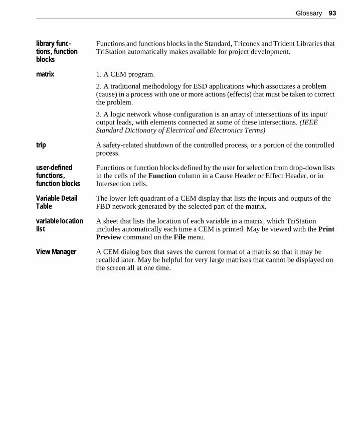
Glossary 93
library func-tions, function blocks
Functions and functions blocks in the Standard, Triconex and Trident Libraries that TriStation automatically makes available for project development.
matrix 1. A CEM program.
2. A traditional methodology for ESD applications which associates a problem (cause) in a process with one or more actions (effects) that must be taken to correct the problem.
3. A logic network whose configuration is an array of intersections of its input/output leads, with elements connected at some of these intersections. (IEEE Standard Dictionary of Electrical and Electronics Terms)
trip A safety-related shutdown of the controlled process, or a portion of the controlled process.
user-defined functions, function blocks
Functions or function blocks defined by the user for selection from drop-down lists in the cells of the Function column in a Cause Header or Effect Header, or in Intersection cells.
Variable Detail Table
The lower-left quadrant of a CEM display that lists the inputs and outputs of the FBD network generated by the selected part of the matrix.
variable location list
A sheet that lists the location of each variable in a matrix, which TriStation includes automatically each time a CEM is printed. May be viewed with the Print Preview command on the File menu.
View Manager A CEM dialog box that saves the current format of a matrix so that it may be recalled later. May be helpful for very large matrixes that cannot be displayed on the screen all at one time.

94 Glossary
Index
AAND’d intersections 7annotations 31Application Type 49, 50, 76, 91attribute assignments 76Attributes dialog box 77Attributes tab 49, 50, 74, 76
Bboundaries
between cells 38BYP (Bypass) terminal 61bypass inputs 61
Ccause
definition 91Cause and Effect Matrix (CEM)
definition 6Cause Header
definition 91description 34
Cause Header Functions 59, 60definition 91
Cause Header Functions option 78Cause Row
definition 91description 34
Cause State 70, 71, 78Cause State variable 72Cause Variable 57cell boundaries
double-clicking 38dragging 38
cellsdeleting from matrix 37hiding and unhiding 39manipulating display of 37selecting in matrix 36selection of multiple 37, 40
CEMdefinition 91
CEM Features attribute 49, 50definition 91
CEM methodology 6CEM program
definition 91CEMPLE
basic functionality 7definition 91installation 9list of features 7toolbar 27training 8
CEM-specific error messages 85colors for monitoring 45, 48
defaults 67comment macros 28Comments field 35contacting Triconex
fax 14phone 13technical support 13web site 14
conventionsused in document 10
DDeclarations dialog box 49, 50
96 Index
de-energize-to-tripapplication 21matrix evaluation 7, 47
default color 67for monitoring 67
default Intersection Function 56default options 48deleting cells 37Description fields 35document conventions 10
Eediting gestures 36
for FBD Network pane 43for Variable Detail Table 40
effectdefinition 92
Effect Columndefinition 92description 34
Effect Headerdefinition 92description 34
Effect Header Functionsoption 78
Effect Header functions 64definition 92
Effect State 74, 78effect state
sharing value 42Effect State variable 75Effect Variable 57Element menu 56, 60, 64, 76Element Options command 56, 60, 64Element Options dialog box 21, 78, 79Emulator Control Panel 66Enable Cause Header Functions option 60Enable Effect Header Functions option 64, 79Enable Intersection Functions option 56energize-to-trip
application 21matrix evaluation 7, 47
error messages 85
evaluationorder of 22
ExCEM.pt2 sample project 47
Ffax number, Triconex 14FBD editor 49, 50FBD Network pane
description 43editing gestures for 43limitations 44
function blockcreating 70
function blockscreating 50design guidelines 70
Function columnof Cause Header 61of Effect Header 65
functionscreating 49, 70design guidelines 70
Hhiding and unhiding cells 39
IIntersection State 78In/Out Var Type 44installing CEMPLE 9instance view 45
definition 92how to monitor 66
Instance View command 66intermediate code
FBD 82FBD and ST 29ST 82
intermediate FBD codedefinition 92
intermediate ST codedefinition 92
Index 97
internal variable 44, 80definition 42, 92
Internet addressfor Triconex 14
Intersection 78definition 92description of 34
Intersection Function 55, 56default 56definition 92
Intersection State 42, 73
Jjournal 27
Llogic sheets 32LVLALRM function 49, 60, 61, 64
Mmacros 28main menu commands 25matrix
definition 93how to edit 33
matrix evaluationtypes of 21
Mon (Monitor) columnof Variable Detail Table 66
monitor colors 45, 48default 67
Monitor Colors tab 67
OOR’d intersections 7order of evaluation 22
Pphone numbers
for Triconex 13polarity
of terminals 24
pop-up menu 24primary input
to Effect Header function or function block 74to Intersection 73
primary inputs 59to Cause Header 71
primary outputfrom Intersection 73of Cause Header 71
primary outputsassociated with Effect State 74
printer setups 32process shutdown 63
Rright mouse button
menu accessible from 24used to select cell in matrix 37
SSafety and Control attribute 49sample project
on CD 47secondary input 59secondary inputs
to Cause Header 71to Effect Header 74
secondary outputsassociated with Effect State 75
selection buttonsfor cells in matrix 36
session journal 27setup program 9sheet templates 32shutdown 21, 63SHUTDOWN function block 50, 64, 65simple matrix
creating 51sizing cells 39
Tterminal polarity 24
98 Index
terminalsunconnected 41
TON function block 55, 56tools
for CEMPLE 27traditional CEM methodology 6Triconex
fax number 14phone numbers 13technical support 13web site 14
trip 21definition 93
Uunhiding cells 39
VVAR_IN_OUT variable type 44Variable Detail Table 93
definition 40editing gestures for 40limitations 40
variable location list 93printing 83
variable nameschanging 41defining 35
variablesassigning to unconnected terminals 41changing names 41
View Manager 30, 81, 93View menu 81
Wweb site
for Triconex 14wires
in FBD network 44


![Simplifying Parallel Programming with Domain Specific ... · Introduction Using DSL for parallel programming ... b are Matrix [Double]) ... Calls Matrix DSL methods Delite applies](https://img.pdfslide.us/doc/110x75/5b54b5447f8b9ae30b8d91ae/simplifying-parallel-programming-with-domain-specific-introduction-using.jpg)