Embed Size (px)
Citation preview

Module 0CATV, DOCSIS 101, Modem Registration
Brady Volpe
1© The Volpe Firm Confidential
Agenda
• CATV Architecture & Overview
• DOCSIS Frequency Allocation
• DOCSIS 1.x / 2.0 Cable Modem Registration
• CM Registration Issues
• Brief eMTA Registration Overview
• Summary
• Q&A
2© The Volpe Firm Confidential
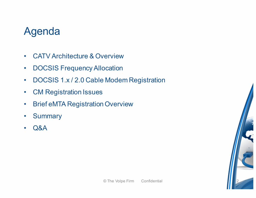
50,000 ft - Cable Architecture
CM
CM
CM
CM
CM
CM
CM
CM
Operator Core Backbone
CMTS
CMTS
CMTS
Aggregation Network Access Network
CM
CM
Operator Aggregation network
Core Network
Operator administered
New Services Opportunities DOCSIS CableHome
•Remote file sharing•Shared calendar•Unified messaging•Managed services
CM
•HVAC control•Fire sense & control•Security•Air quality monitoring•Child monitoring•Energy management, etc.
PacketCable
MPEG Services
IP Services
CPEHeadendBackend
PSTNWireless
3© The Volpe Firm Confidential
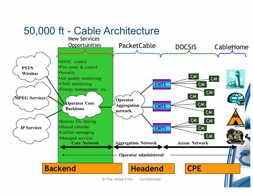
Off-The-Air– Reception and distribution on a fairly small coverage (local)
– Objective: TV Sales
– Unregulated
– In 1948 in Montréal, 2 channels are distributed (also WA & PA)• Rediffusion
• American Channel
– Modified Television
• AGC measurements
– (Automatic Gain Control)
Measurements
-First measurement: signal level4© The Volpe Firm Confidential
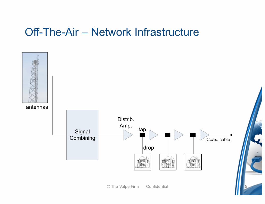
Off-The-Air – Network Infrastructure
antennas
SignalCombining
Distrib.Amp.
tap
dropCoax. cable
5© The Volpe Firm Confidential
Satellites and Microwaves– New programming
• Each city has its own programming
– Wide distribution
• Local, distant, community-based program
• The use of satellites is expensive so distribution in suburbs and villages are with long cascading amplifier
– More channels
• From 21 to 50 channels (Mid-band use, then super band)
– Regulation
• FCC (in United States)
• BP-23 (in Canada)
– Long cascades of amplifiers
• From 10 to 80 amplifiers
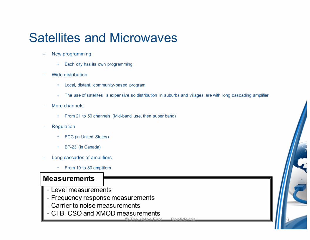
Measurements- Level measurements- Frequency response measurements- Carrier to noise measurements- CTB, CSO and XMOD measurements
6© The Volpe Firm Confidential
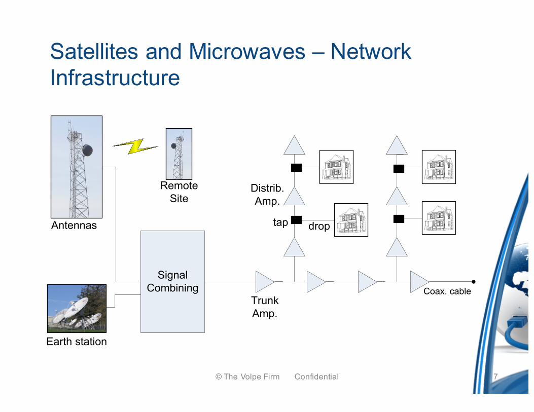
Satellites and Microwaves – Network Infrastructure
Antennas
SignalCombining
TrunkAmp.
Earth station
Distrib.Amp.
RemoteSite
tap drop
Coax. cable
7© The Volpe Firm Confidential
PAY-TV and Extended Services
– New programming
– Scrambling (and hackers)
– Channel converter
– Channel converter with decoding
– Data transmission toward the channel converter with decoding
– Upstream transmission first try
8© The Volpe Firm Confidential
Measurements- Need for more accurate measurements (Subscribers pay for a better quality of service)- Measurement methods standardization to meet FCC standards (NCTA, SCTE)
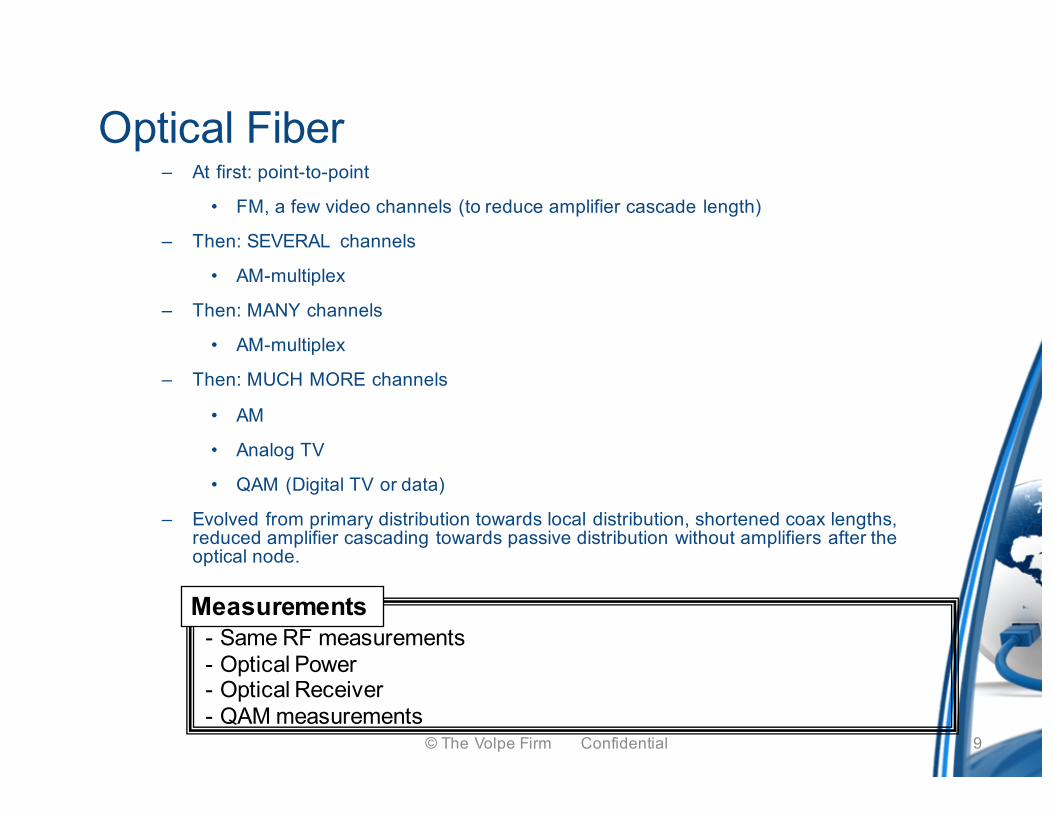
Optical Fiber– At first: point-to-point
• FM, a few video channels (to reduce amplifier cascade length)
– Then: SEVERAL channels
• AM-multiplex
– Then: MANY channels
• AM-multiplex
– Then: MUCH MORE channels
• AM
• Analog TV
• QAM (Digital TV or data)
– Evolved from primary distribution towards local distribution, shortened coax lengths, reduced amplifier cascading towards passive distribution without amplifiers after the optical node.
Measurements- Same RF measurements- Optical Power- Optical Receiver- QAM measurements
9© The Volpe Firm Confidential
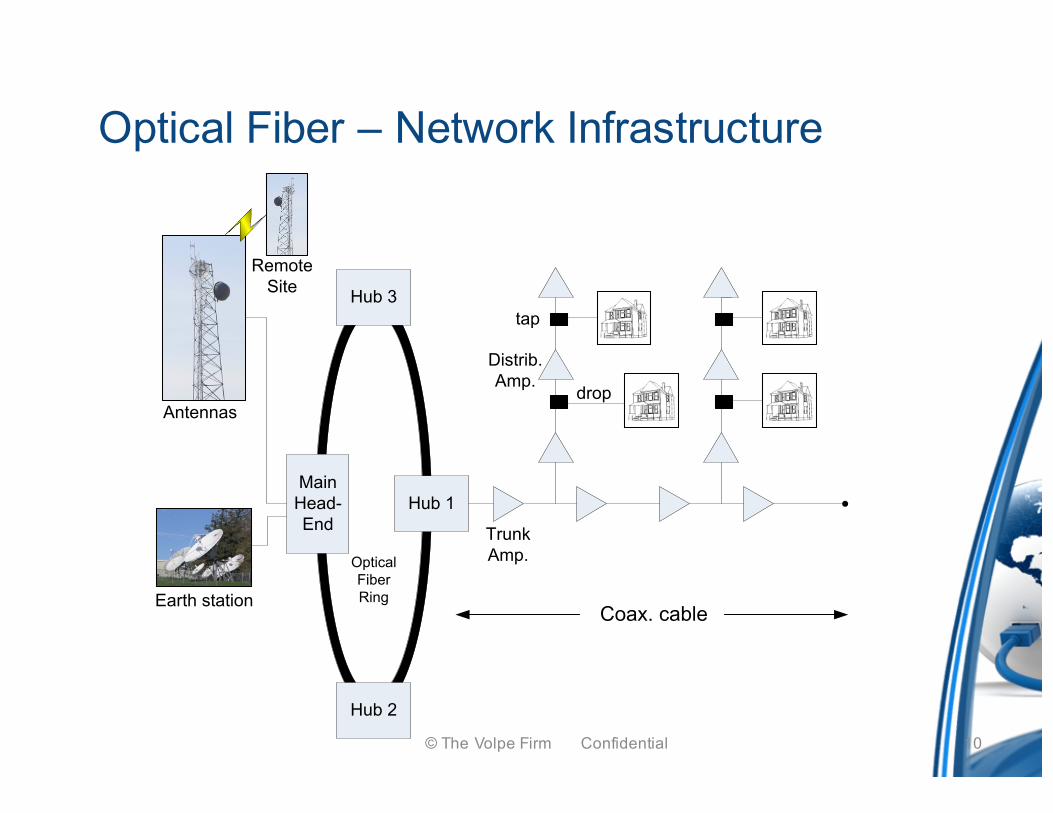
Optical Fiber – Network Infrastructure
Antennas
TrunkAmp.
Earth station
Distrib.Amp.
RemoteSite
MainHead-End
Hub 1
Hub 3
Hub 2
OpticalFiberRing
Coax. cable
tap
drop
10© The Volpe Firm Confidential
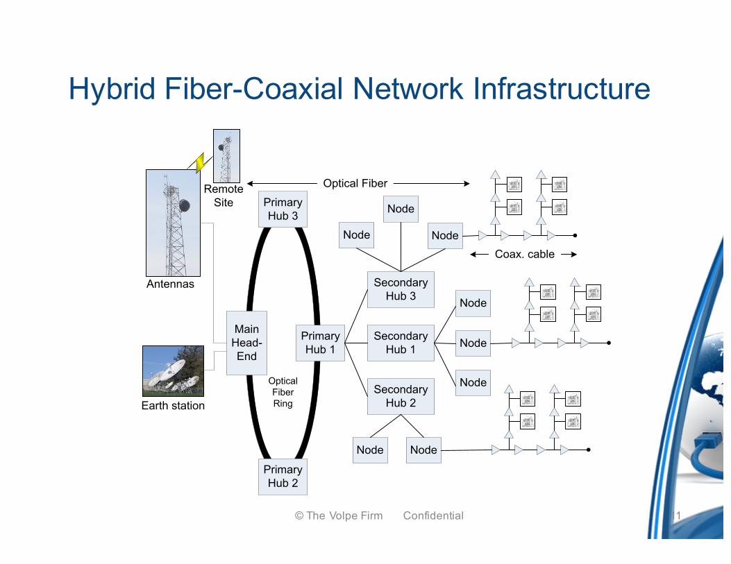
Hybrid Fiber-Coaxial Network Infrastructure
Antennas
Earth station
RemoteSite
MainHead-End
PrimaryHub 1
PrimaryHub 3
PrimaryHub 2
OpticalFiberRing
Secondary Hub 1
Node
Node
Node
Node
Node Node
Node
Node
Secondary Hub 2
Secondary Hub 3
Coax. cable
Optical Fiber
11© The Volpe Firm Confidential
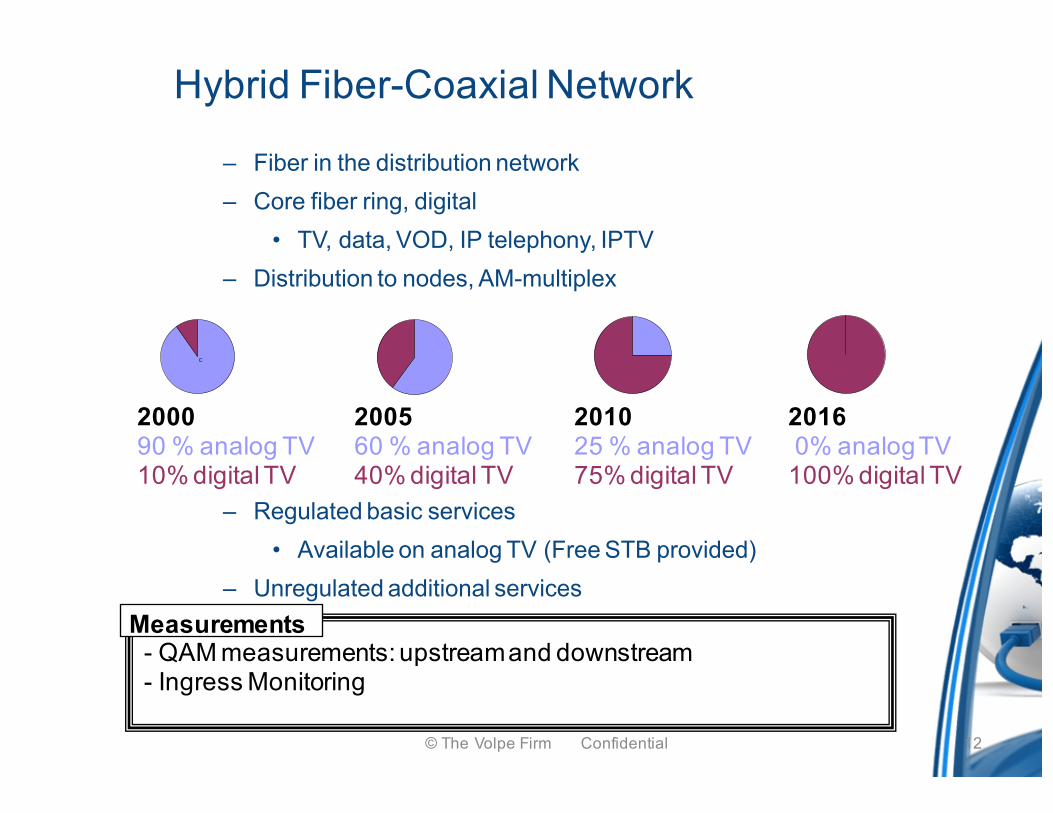
– Fiber in the distribution network– Core fiber ring, digital
• TV, data, VOD, IP telephony, IPTV– Distribution to nodes, AM-multiplex
– Regulated basic services• Available on analog TV (Free STB provided)
– Unregulated additional services
Hybrid Fiber-Coaxial Network
Measurements- QAM measurements: upstream and downstream- Ingress Monitoring
C
200090 % analog TV10% digital TV
200560 % analog TV40% digital TV
201025 % analog TV75% digital TV
20160% analog TV 100% digital TV
12© The Volpe Firm Confidential
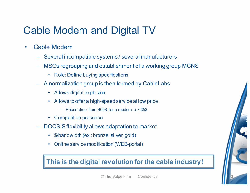
Cable Modem and Digital TV• Cable Modem
– Several incompatible systems / several manufacturers– MSOs regrouping and establishment of a working group MCNS
• Role: Define buying specifications
– A normalization group is then formed by CableLabs• Allows digital explosion• Allows to offer a high-speed service at low price
– Prices drop from 400$ for a modem to <35$
• Competition presence
– DOCSIS flexibility allows adaptation to market• $/bandwidth (ex.: bronze, silver, gold)
• Online service modification (WEB-portal)
13© The Volpe Firm Confidential
This is the digital revolution for the cable industry!
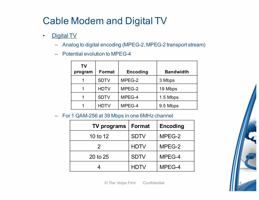
Cable Modem and Digital TV• Digital TV
– Analog to digital encoding (MPEG-2, MPEG-2 transport stream)
– Potential evolution to MPEG-4
– For 1 QAM-256 at 39 Mbps in one 6MHz channel
TV program Format Encoding Bandwidth
1 SDTV MPEG-2 3 Mbps
1 HDTV MPEG-2 19 Mbps
1 SDTV MPEG-4 1.5 Mbps
1 HDTV MPEG-4 9.5 Mbps
TV programs Format Encoding
10 to 12 SDTV MPEG-2
2 HDTV MPEG-2
20 to 25 SDTV MPEG-4
4 HDTV MPEG-4
14© The Volpe Firm Confidential
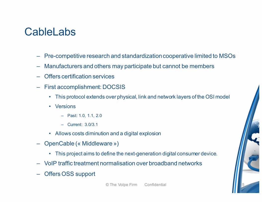
CableLabs
– Pre-competitive research and standardization cooperative limited to MSOs
– Manufacturers and others may participate but cannot be members
– Offers certification services
– First accomplishment: DOCSIS• This protocol extends over physical, link and network layers of the OSI model
• Versions– Past: 1.0, 1.1, 2.0
– Current: 3.0/3.1
• Allows costs diminution and a digital explosion
– OpenCable (« Middleware »)• This project aims to define the next-generation digital consumer device.
– VoIP traffic treatment normalisation over broadband networks
– Offers OSS support15© The Volpe Firm Confidential
© T
he V
olpe
Firm
Con
fiden
tial
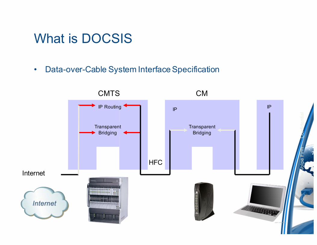
What is DOCSIS
• Data-over-Cable System Interface Specification
16
CMTS CM
CPE
Transparent Bridging
IPIP Routing
Transparent Bridging
IP
HFCInternet

DOCSIS 101 & Modem Registration
17© The Volpe Firm Confidential
Downstreamf
5 42 54 860MHz
Upstream
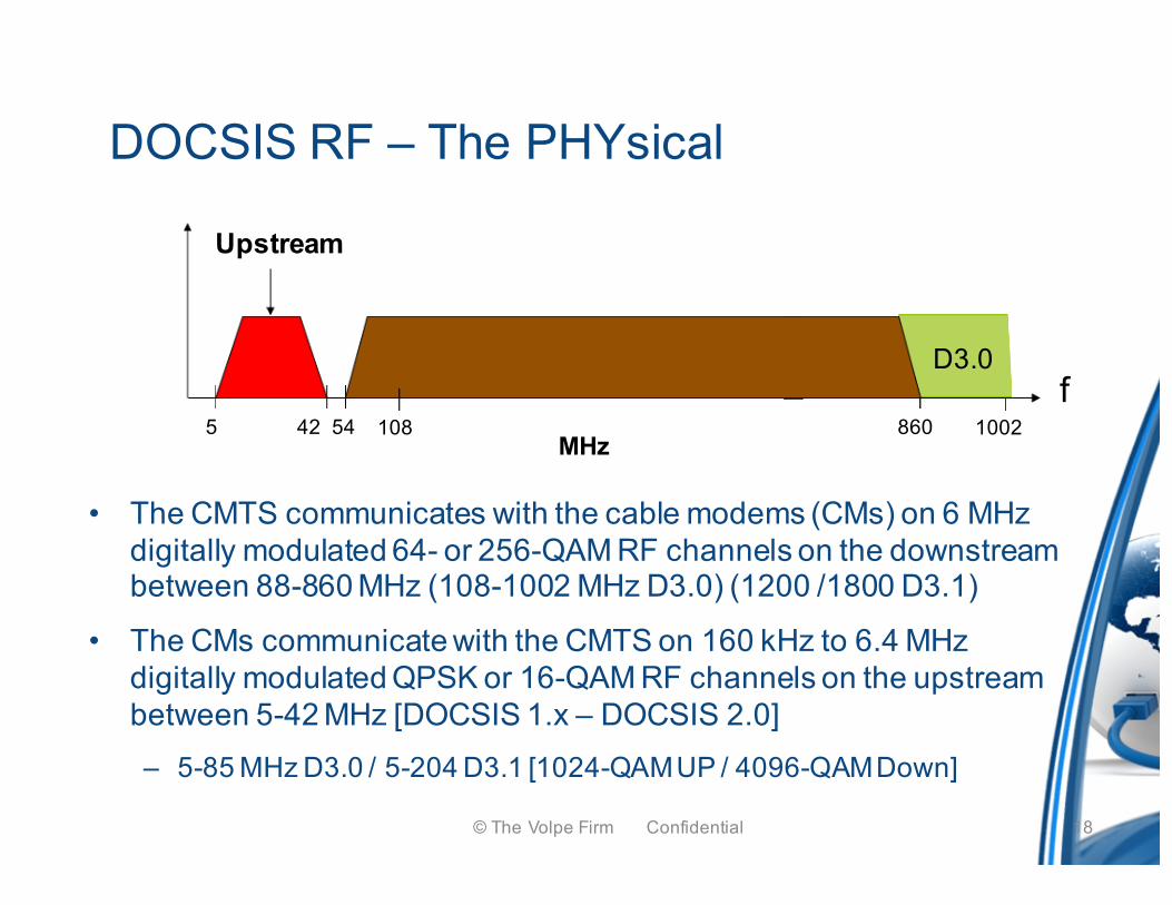
DOCSIS RF – The PHYsical
• The CMTS communicates with the cable modems (CMs) on 6 MHz digitally modulated 64- or 256-QAM RF channels on the downstream between 88-860 MHz (108-1002 MHz D3.0) (1200 /1800 D3.1)
• The CMs communicate with the CMTS on 160 kHz to 6.4 MHz digitally modulated QPSK or 16-QAM RF channels on the upstream between 5-42 MHz [DOCSIS 1.x – DOCSIS 2.0] – 5-85 MHz D3.0 / 5-204 D3.1 [1024-QAM UP / 4096-QAM Down]
18© The Volpe Firm Confidential
1002
D3.0
108
Server 1Server 2Server 3
IP Data Backbone
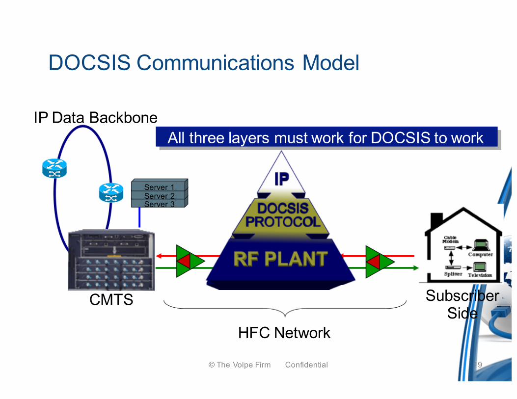
DOCSIS Communications Model
CMTS
HFC Network
SubscriberSide
All three layers must work for DOCSIS to work
19© The Volpe Firm Confidential
Cable Modem Registration
– CM registration requires the physical layer for signal transport
– DOCSIS and IP protocol layers are necessary to communicate the proper messages for modems to come online
– The next slides illustrate the interaction of these layers
20© The Volpe Firm Confidential
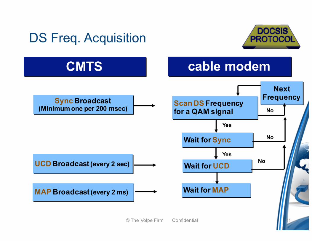
DS Freq. Acquisition
CMTS cable modem
Wait for UCD
Wait for MAP
Wait for Sync
Yes
No
NextFrequency
Yes
No
No
Sync Broadcast(Minimum one per 200 msec)
UCD Broadcast (every 2 sec)
MAP Broadcast (every 2 ms)
Scan DS Frequency for a QAM signal
21© The Volpe Firm Confidential
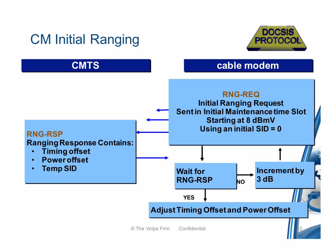
CMTS cable modem
Adjust Timing Offset and Power Offset
Wait forRNG-RSP NO
YES
RNG-RSPRanging Response Contains:
• Timing offset• Power offset• Temp SID
RNG-REQInitial Ranging Request
Sent in Initial Maintenance time Slot Starting at 8 dBmV
Using an initial SID = 0
Increment by3 dB
CM Initial Ranging
22© The Volpe Firm Confidential
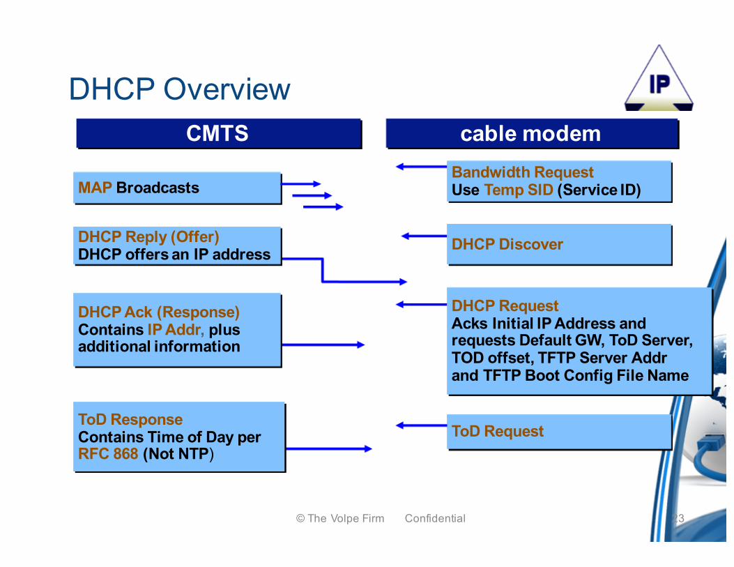
DHCP OverviewCMTS
DHCP RequestAcks Initial lP Address andrequests Default GW, ToD Server,TOD offset, TFTP Server Addrand TFTP Boot Config File Name
cable modem
MAP Broadcasts
ToD Request
DHCP DiscoverDHCP Reply (Offer)DHCP offers an IP address
Bandwidth Request Use Temp SID (Service ID)
ToD ResponseContains Time of Day perRFC 868 (Not NTP)
DHCP Ack (Response)Contains IP Addr, plusadditional information
23© The Volpe Firm Confidential
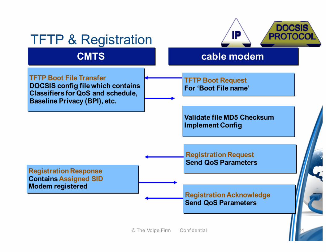
TFTP & RegistrationCMTS cable modem
TFTP Boot File TransferDOCSIS config file which containsClassifiers for QoS and schedule,Baseline Privacy (BPI), etc.
Registration RequestSend QoS Parameters
Validate file MD5 ChecksumImplement Config
TFTP Boot RequestFor ‘Boot File name’
Registration ResponseContains Assigned SIDModem registered
Registration AcknowledgeSend QoS Parameters
24© The Volpe Firm Confidential
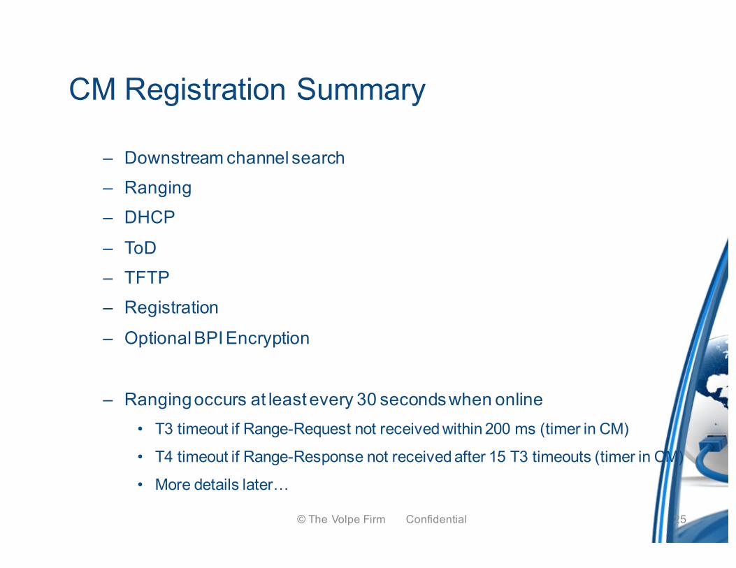
CM Registration Summary
– Downstream channel search– Ranging– DHCP
– ToD– TFTP– Registration
– Optional BPI Encryption
– Ranging occurs at least every 30 seconds when online• T3 timeout if Range-Request not received within 200 ms (timer in CM)
• T4 timeout if Range-Response not received after 15 T3 timeouts (timer in CM)
• More details later…
25© The Volpe Firm Confidential
CM Registration Issues
• Scanning frequencies fixed in CM may not align with MSO channels– MSO may ask for custom configuration of scanning tables
• Bootp flag – unicast vs. broadcast, DHCP server can ignore • CM must adhere exactly to DOCSIS & network spec. on DHCP options
or will fail DHCP – stuck in “init(d)”• Most CM manufactures have custom MIB strings
– These need to be published and documented– Generic config files are often used, will CM work without MIB strings?
• CM support for long (64+ character TFTP file names)• Do not cash TFTP server IP or any IP address when given a new one
– Common mistake when TFTP address proxy is used
• You should test registration with every make, model & IOS configuration available – you will fail registration somewhere – fix code
26© The Volpe Firm Confidential
CM Registration Issues (cont.)
• BPI+ key exchange – simple process, but some CMTSs and their configurations will cause issues– Make sure to test with different scenarios, models, IOS, mandates
• Modulation profiles – TDMA, A-TDMA, S-CDMA, mixed– Include testing with logical channels of above mixes
– Issues especially occur in 1.x/2.0 mode where QPSK and m-QAM power differs by as much as 6 dB – total RF power should remain constant
• This will cause laser clipping if you do not follow spec.
• Poor clocks lead to modems who drift out of time slot– CMTS cannot correct through station maintenance
– CM is TX over top of another CM
– Allowed to stay online up to 499 µsec
– Have seen 5% of low quality modems do this – no longer in business27© The Volpe Firm Confidential
CM Registration Issues (cont.)
• CM must support FW remote upgrade through CVC (BPI+ spec)– Failures of upgrade will disable CM and cause truck roll
• CMs lock up at IP layer (can’t ping at IP), but stay online at layer 2– Can still ping modem using Layer 2 ping (was Cisco proprietary)– Some vendors have resolved this problem through watchdog timer to
reboot the modem
• ARP storm filtering / immunity– Hackers create ARP traffic in DOCSIS IP network, overwhelming CM
– Your CM must be immune to this and other types of DoS broadcast traffic
• Security – Hackers will try to use your CM for theft of service– Bypass BPI+, SNMP, MIBs, etc.
– Ensure there are no back doors in your CM or you will blacklisted
28© The Volpe Firm Confidential
CM Registration Issues (cont.)
• RF immunity / radiation– Your modem must be shielded so that it is not an ingress point
– It also must not inject noise into the plant
– Make sure there are no harmonics or spurs during TX periods
– Look at large sample sizes and subsequent batches of modems
29© The Volpe Firm Confidential
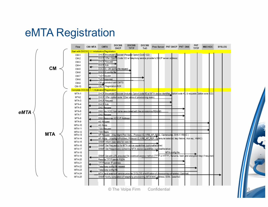
eMTA Registration
CM
MTA
eMTA
30© The Volpe Firm Confidential
31
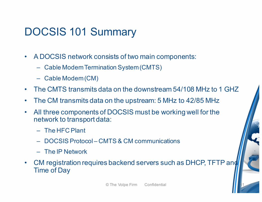
DOCSIS 101 Summary
• A DOCSIS network consists of two main components:– Cable Modem Termination System (CMTS)
– Cable Modem (CM)
• The CMTS transmits data on the downstream 54/108 MHz to 1 GHZ• The CM transmits data on the upstream: 5 MHz to 42/85 MHz• All three components of DOCSIS must be working well for the
network to transport data:– The HFC Plant– DOCSIS Protocol – CMTS & CM communications– The IP Network
• CM registration requires backend servers such as DHCP, TFTP and Time of Day
© The Volpe Firm Confidential
VOICE OVER IP(VOIP)
32© The Volpe Firm Confidential
Agenda
• Call Quality
• Types of VoIP Impairments
• Troubleshooting
• Cause & Effect
• Q & A
© The Volpe Firm Confidential 33
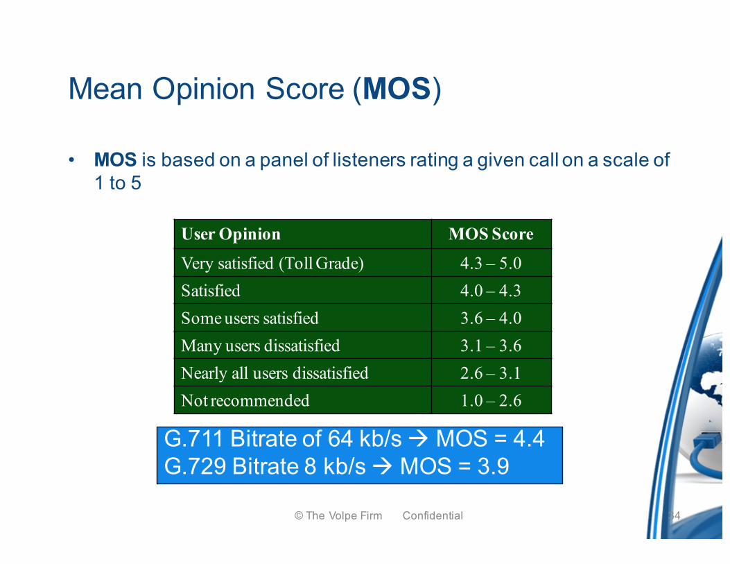
User Opinion MOS Score
Very satisfied (Toll Grade) 4.3 – 5.0Satisfied 4.0 – 4.3Some users satisfied 3.6 – 4.0Many users dissatisfied 3.1 – 3.6Nearly all users dissatisfied 2.6 – 3.1Not recommended 1.0 – 2.6
Call Quality - MOS
G.711 Bitrate of 64 kb/s à MOS = 4.4G.729 Bitrate 8 kb/s à MOS = 3.9
Mean Opinion Score (MOS)
• MOS is based on a panel of listeners rating a given call on a scale of 1 to 5
© The Volpe Firm Confidential 34
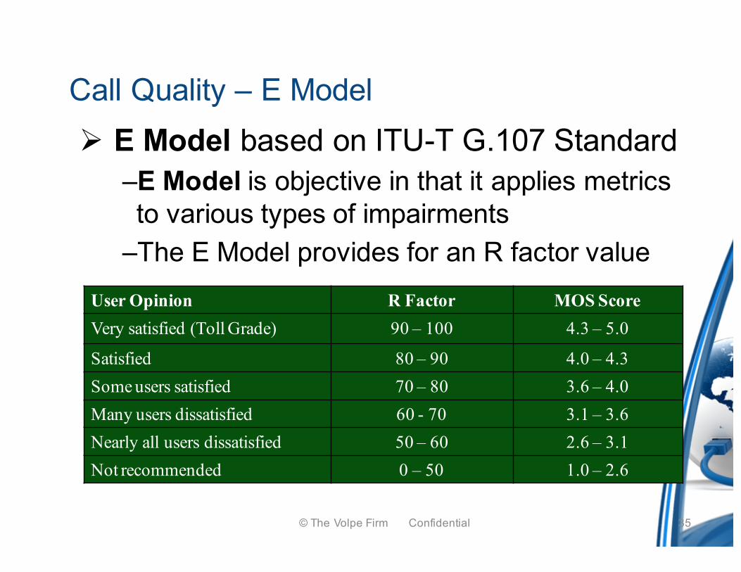
Ø E Model based on ITU-T G.107 Standard–E Model is objective in that it applies metrics to various types of impairments
–The E Model provides for an R factor valueUser Opinion R Factor MOS ScoreVery satisfied (Toll Grade) 90 – 100 4.3 – 5.0
Satisfied 80 – 90 4.0 – 4.3Some users satisfied 70 – 80 3.6 – 4.0Many users dissatisfied 60 - 70 3.1 – 3.6Nearly all users dissatisfied 50 – 60 2.6 – 3.1Not recommended 0 – 50 1.0 – 2.6
Call Quality – E Model
© The Volpe Firm Confidential 35
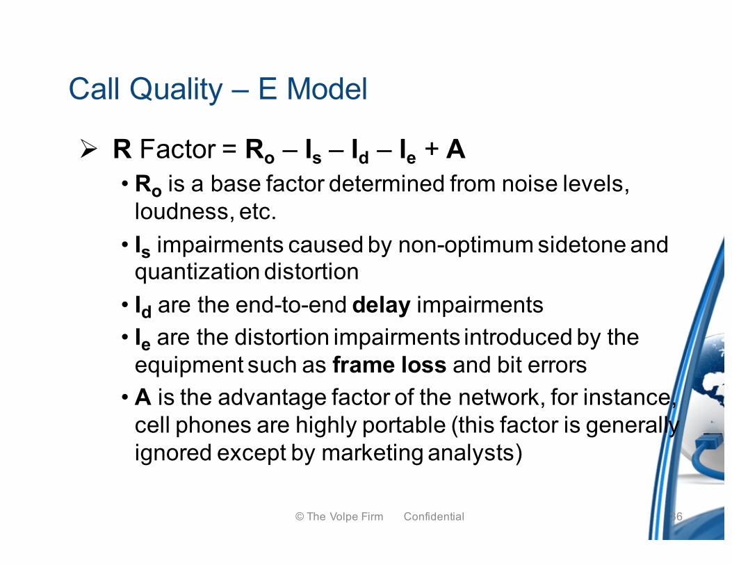
Ø R Factor = Ro – Is – Id – Ie + A• Ro is a base factor determined from noise levels,
loudness, etc. • Is impairments caused by non-optimum sidetone and
quantization distortion• Id are the end-to-end delay impairments• Ie are the distortion impairments introduced by the
equipment such as frame loss and bit errors• A is the advantage factor of the network, for instance,
cell phones are highly portable (this factor is generally ignored except by marketing analysts)
Call Quality – E Model
© The Volpe Firm Confidential 36
Defining the Problem
• Often VoIP problems begin with a CSR ticket from a subscriber complaint – a vague description of bad voice quality
• Two days later a truck is rolled• If the problem still exists, it’s a good day!
• Often times the problem has gone awayRF levels are goodVoIP scores are good
• It may come back several days later• Another CSR ticket, another truck roll…
© The Volpe Firm Confidential 37
Defining the Problem
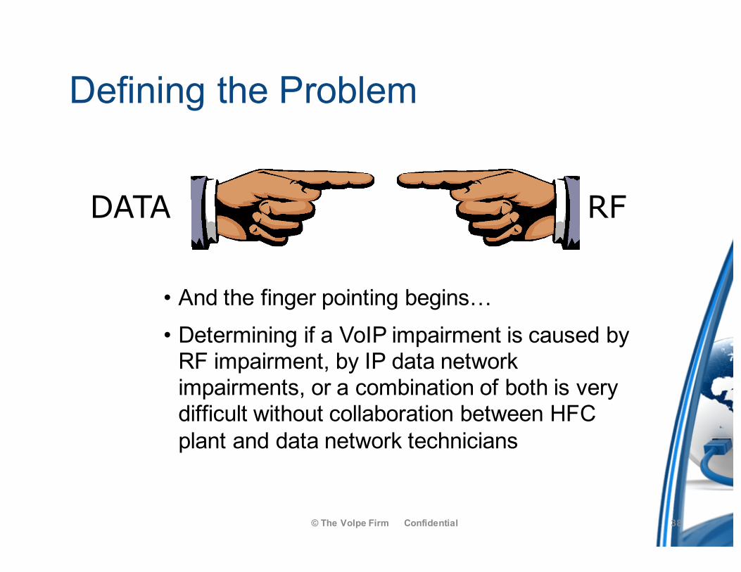
© The Volpe Firm Confidential 38
• And the finger pointing begins…• Determining if a VoIP impairment is caused by
RF impairment, by IP data network impairments, or a combination of both is very difficult without collaboration between HFC plant and data network technicians
RFDATA
Troubleshooting Methodology
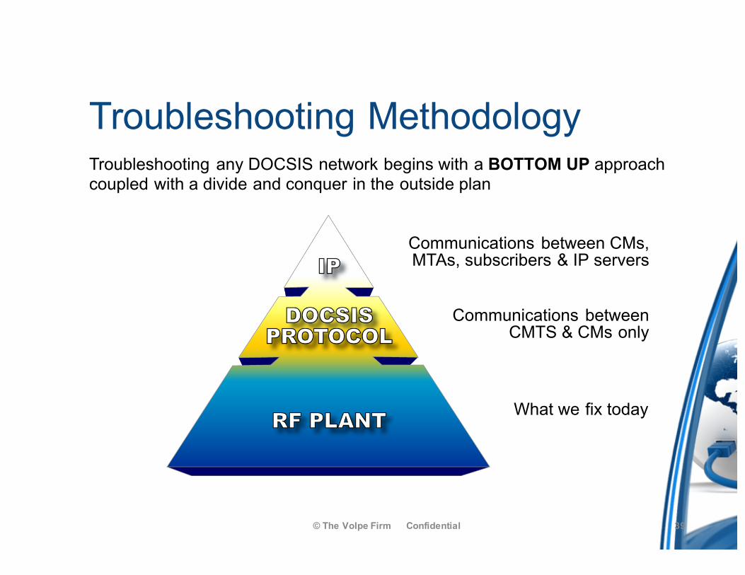
© The Volpe Firm Confidential 39
What we fix today
Communications betweenCMTS & CMs only
Communications between CMs,MTAs, subscribers & IP servers
Troubleshooting any DOCSIS network begins with a BOTTOM UP approach coupled with a divide and conquer in the outside plan
Building Blocks of Troubleshooting
© The Volpe Firm Confidential 40
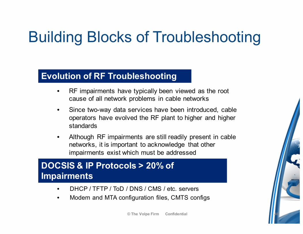
• DHCP / TFTP / ToD / DNS / CMS / etc. servers• Modem and MTA configuration files, CMTS configs
• RF impairments have typically been viewed as the root cause of all network problems in cable networks
• Since two-way data services have been introduced, cable operators have evolved the RF plant to higher and higher standards
• Although RF impairments are still readily present in cable networks, it is important to acknowledge that other impairments exist which must be addressed
Evolution of RF Troubleshooting
DOCSIS & IP Protocols > 20% of Impairments
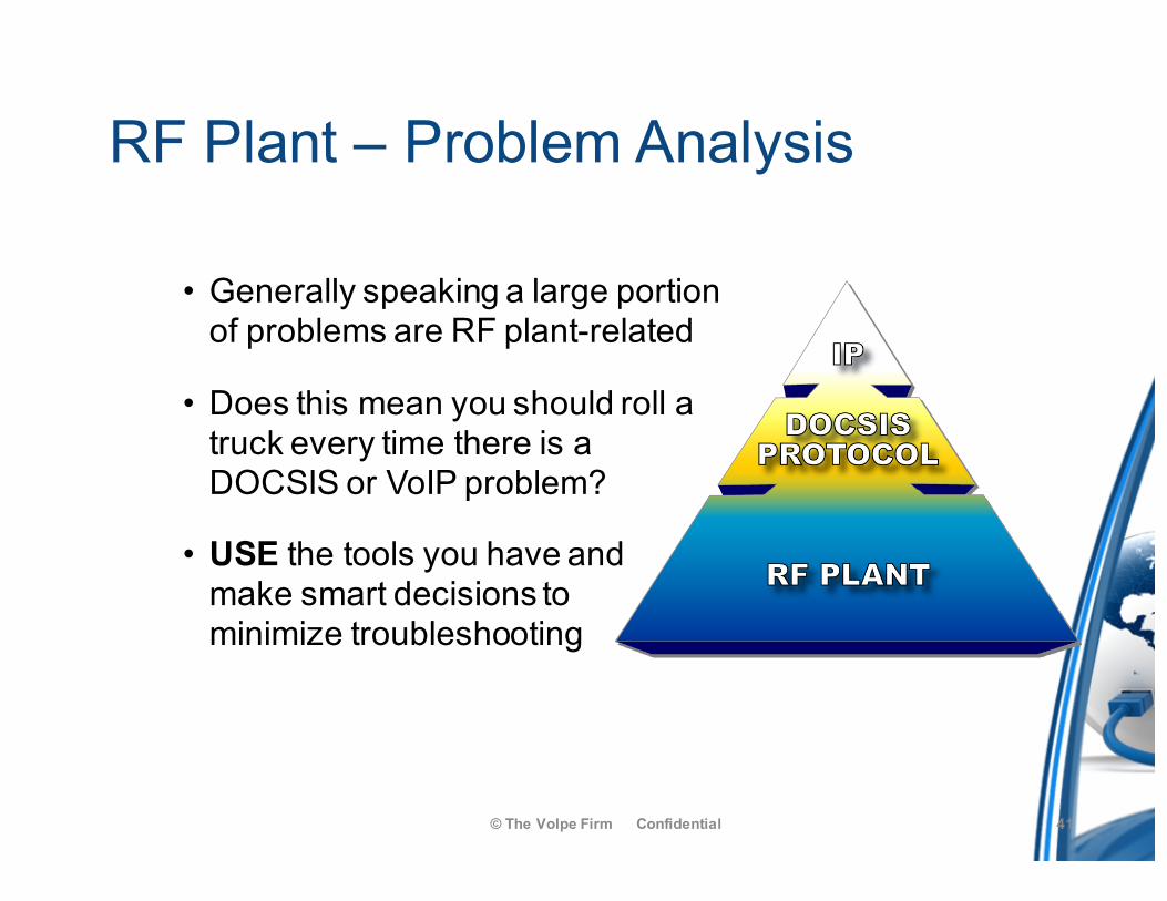
RF Plant – Problem Analysis
© The Volpe Firm Confidential 41
• Generally speaking a large portion of problems are RF plant-related
• Does this mean you should roll a truck every time there is a DOCSIS or VoIP problem?
• USE the tools you have and make smart decisions to minimize troubleshooting
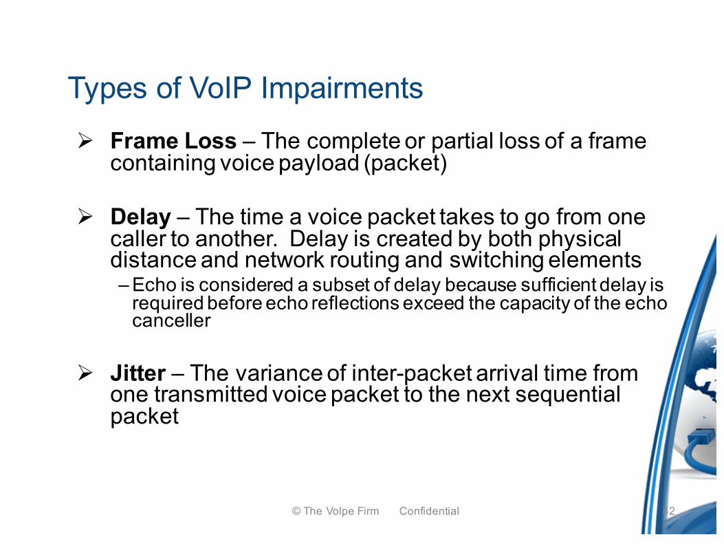
Ø Frame Loss – The complete or partial loss of a frame containing voice payload (packet)
Ø Delay – The time a voice packet takes to go from one caller to another. Delay is created by both physical distance and network routing and switching elements– Echo is considered a subset of delay because sufficient delay is
required before echo reflections exceed the capacity of the echo canceller
Ø Jitter – The variance of inter-packet arrival time from one transmitted voice packet to the next sequential packet
Types of VoIP Impairments
© The Volpe Firm Confidential 42
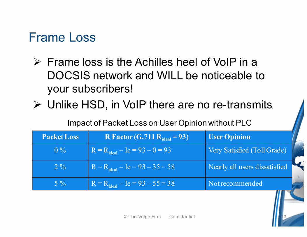
Ø Frame loss is the Achilles heel of VoIP in a DOCSIS network and WILL be noticeable to your subscribers!
Ø Unlike HSD, in VoIP there are no re-transmits
Frame Loss
Packet Loss R Factor (G.711 Rideal = 93) User Opinion
0 % R = Rideal – Ie = 93 – 0 = 93 Very Satisfied (Toll Grade)
2 % R = Rideal – Ie = 93 – 35 = 58 Nearly all users dissatisfied
5 % R = Rideal – Ie = 93 – 55 = 38 Not recommended
Impact of Packet Loss on User Opinion without PLC
© The Volpe Firm Confidential 43
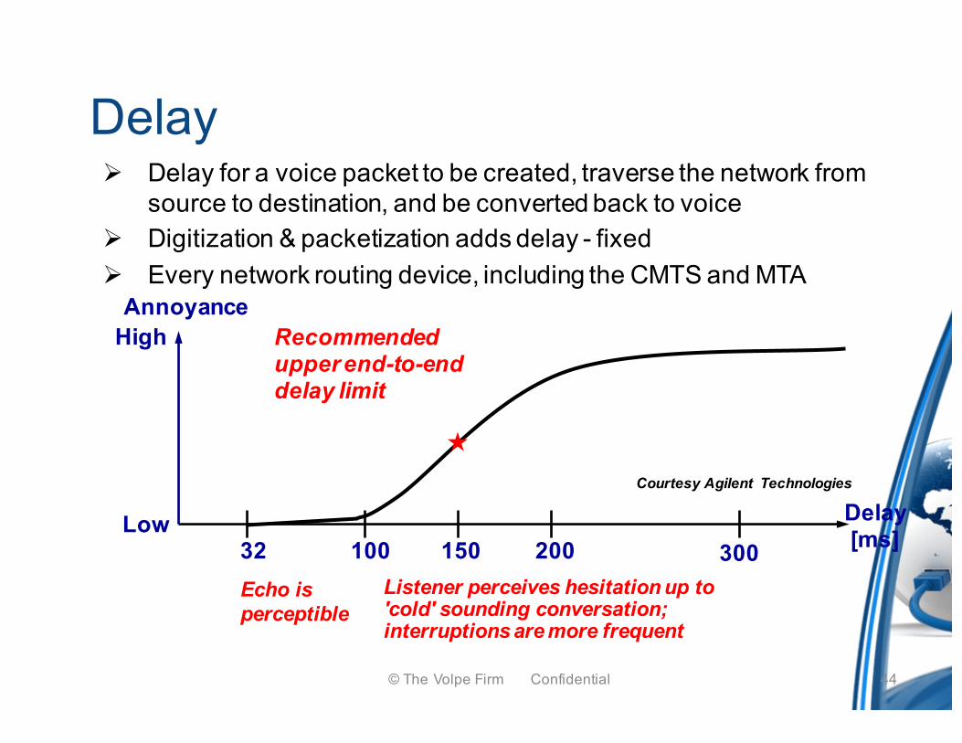
Ø Delay for a voice packet to be created, traverse the network from source to destination, and be converted back to voice
Ø Digitization & packetization adds delay - fixedØ Every network routing device, including the CMTS and MTA
Delay
Echo is perceptible
Annoyance
Delay[ms]32 100 150 200 300
Recommended upper end-to-end delay limit
«
Listener perceives hesitation up to 'cold' sounding conversation; interruptions are more frequent
Low
High
Courtesy Agilent Technologies
© The Volpe Firm Confidential 44
Service Flows
• Service Flows guarantee that one traffic flow has a higher priority of service than others
• For instance VoIP or IP Video over traffic has higher precedence than does email, gaming, P2P file sharing, or even non-managed VoIP services such as Vonage
• Static service flows are sometimes used for businesses where T1 equivalent service is desired to be provided continuously
• Dynamic service flows are the typical for VoIP or IP Video – this is the service flow an eMTA creates
© The Volpe Firm Confidential 45
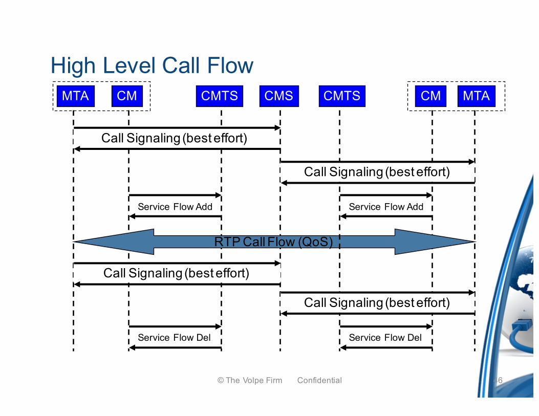
High Level Call Flow
Call Signaling (best effort)
MTA CM CMTS CMS CM MTA
RTP Call Flow (QoS)
CMTS
Call Signaling (best effort)
Service Flow Add Service Flow Add
Call Signaling (best effort)
Call Signaling (best effort)
Service Flow Del Service Flow Del
© The Volpe Firm Confidential 46
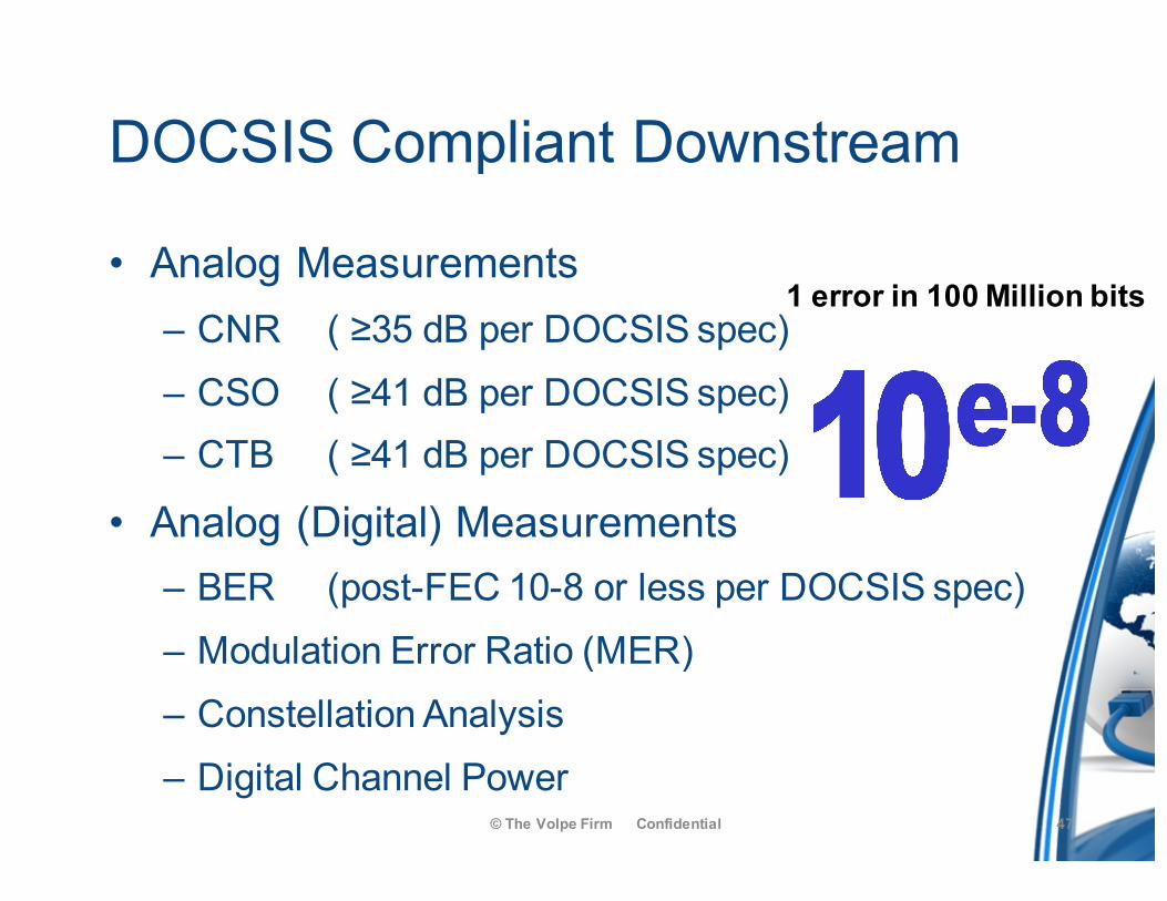
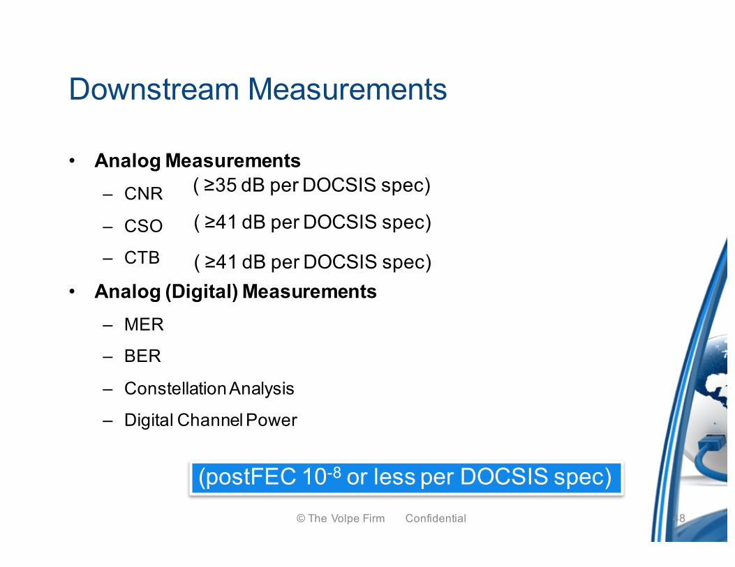
DOCSIS Compliant Downstream
• Analog Measurements– CNR ( ≥35 dB per DOCSIS spec)– CSO ( ≥41 dB per DOCSIS spec)– CTB ( ≥41 dB per DOCSIS spec)
• Analog (Digital) Measurements– BER (post-FEC 10-8 or less per DOCSIS spec)– Modulation Error Ratio (MER)– Constellation Analysis– Digital Channel Power
© The Volpe Firm Confidential 47
1 error in 100 Million bits
• Analog Measurements– CNR
– CSO
– CTB
• Analog (Digital) Measurements– MER
– BER
– Constellation Analysis
– Digital Channel Power
Downstream Measurements
( ≥35 dB per DOCSIS spec)
( ≥41 dB per DOCSIS spec)
( ≥41 dB per DOCSIS spec)
(postFEC 10-8 or less per DOCSIS spec)© The Volpe Firm Confidential 48
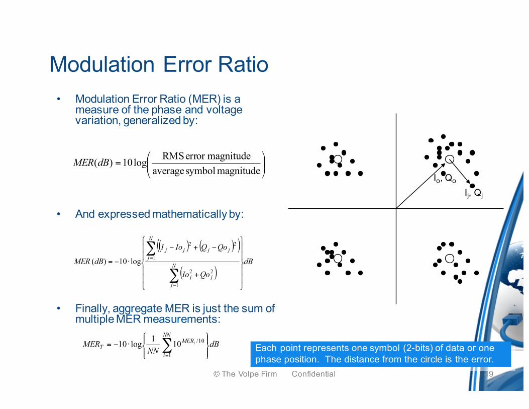
Modulation Error Ratio• Modulation Error Ratio (MER) is a
measure of the phase and voltage variation, generalized by:
• And expressed mathematically by:
• Finally, aggregate MER is just the sum of multiple MER measurements:
( ) ( )( )
( )dB
QoIo
QoQIoI
dBMER N
jjj
N
jjjjj
⎪⎪
⎭
⎪⎪
⎬
⎫
⎪⎪
⎩
⎪⎪
⎨
⎧
+
−+−
⋅−=
∑
∑
=
=
1
22
1
22
log10)(
⎟⎟⎠
⎞⎜⎜⎝
⎛=
magnitude symbol averagemagnitudeerror RMSlog10)(dBMER
dBNN
MERNN
i
MERT
i
⎪⎭
⎪⎬⎫
⎪⎩
⎪⎨⎧
⋅−= ∑=1
10/101log10
Io, Qo
Ij, Qj
Each point represents one symbol (2-bits) of data or onephase position. The distance from the circle is the error.
© The Volpe Firm Confidential 49
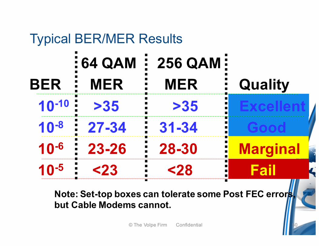
Typical BER/MER Results
Note: Set-top boxes can tolerate some Post FEC errors, but Cable Modems cannot.
64 QAM 256 QAMBER MER MER Quality
10-10 >35 >35 Excellent10-8 27-34 31-34 Good10-6 23-26 28-30 Marginal10-5 <23 <28 Fail
© The Volpe Firm Confidential 50
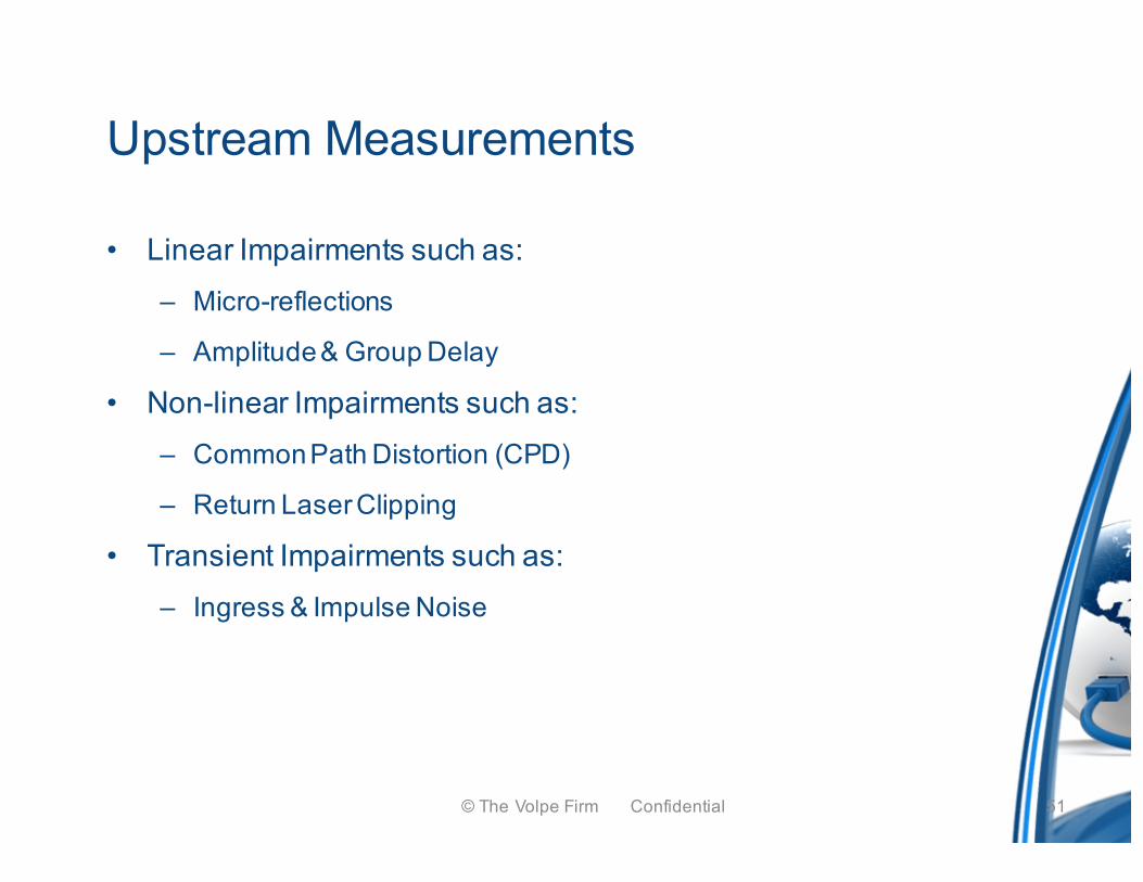
Upstream Measurements
• Linear Impairments such as:– Micro-reflections
– Amplitude & Group Delay
• Non-linear Impairments such as:– Common Path Distortion (CPD)
– Return Laser Clipping
• Transient Impairments such as:– Ingress & Impulse Noise
© The Volpe Firm Confidential 51
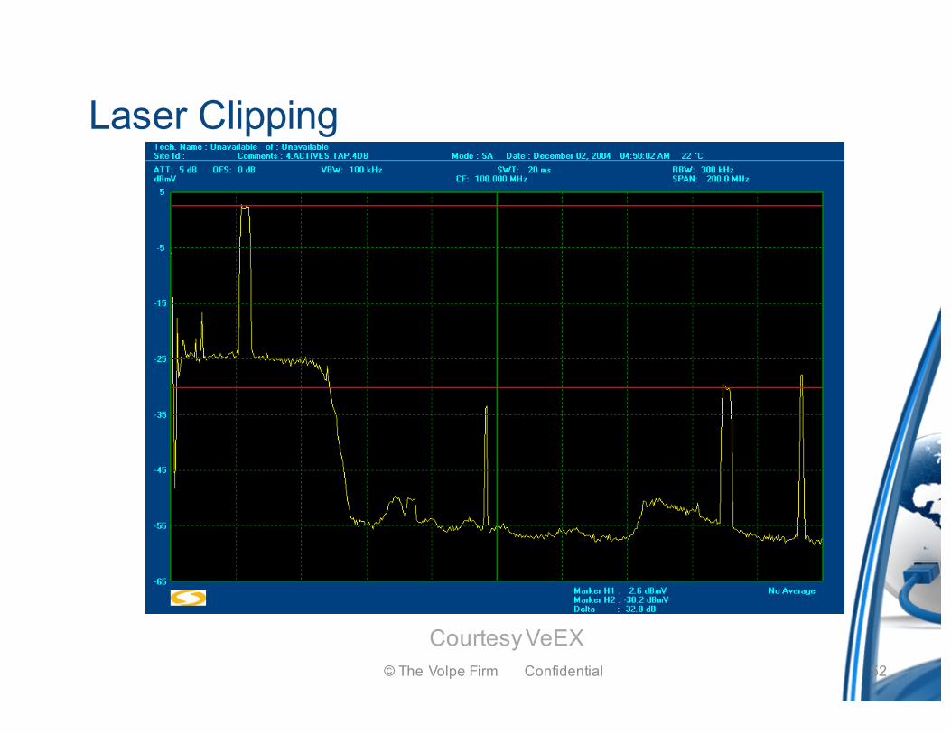
Laser Clipping
Courtesy VeEX© The Volpe Firm Confidential 52
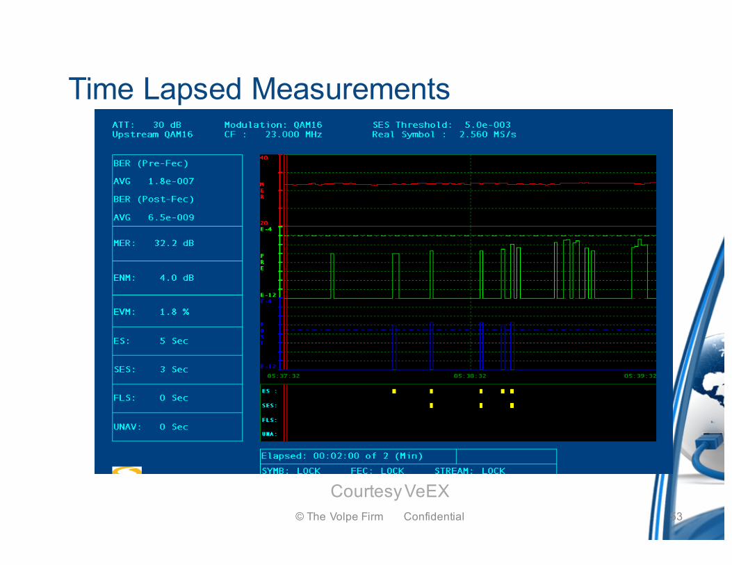
Time Lapsed Measurements
Courtesy VeEX© The Volpe Firm Confidential 53
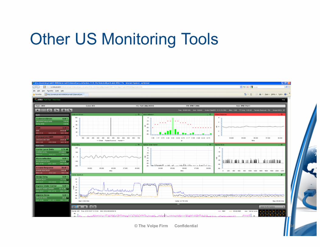
Other US Monitoring Tools
© The Volpe Firm Confidential 54
55© The Volpe Firm Confidential
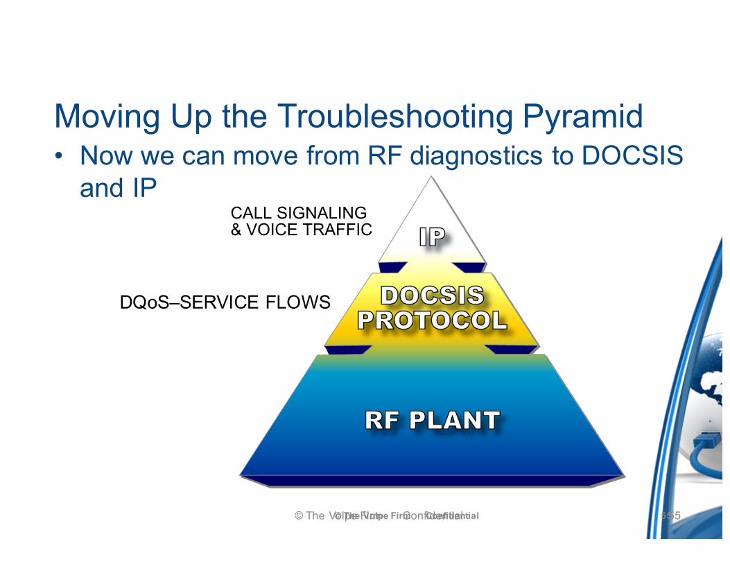
Moving Up the Troubleshooting Pyramid• Now we can move from RF diagnostics to DOCSIS
and IP
© The Volpe Firm Confidential
CALL SIGNALING& VOICE TRAFFIC
DQoS–SERVICE FLOWS
55
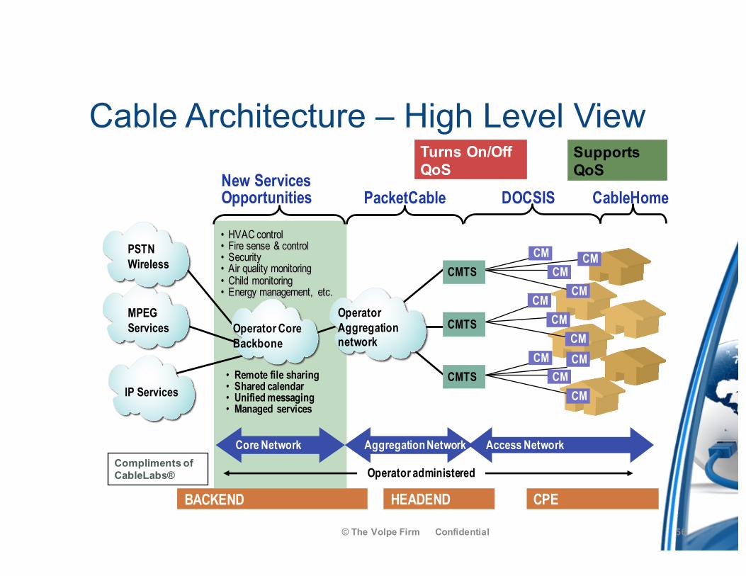
Cable Architecture – High Level View
© The Volpe Firm Confidential
Supports QoS
Turns On/Off QoS
CMCM
CMCM
CM
CMCM
CM
CMTS
CMTS
CMTS
CM
CM
Operator administered
New Services Opportunities DOCSIS CableHome
• Remote file sharing• Shared calendar• Unified messaging• Managed services
CM
• HVAC control• Fire sense & control• Security• Air quality monitoring• Child monitoring• Energy management, etc.
PacketCable
CPEHEADENDBACKEND
Compliments of CableLabs®
Operator Core Backbone
Core Network Aggregation Network Access Network
MPEGServices
IP Services
PSTNWireless
Operator Aggregation network
56
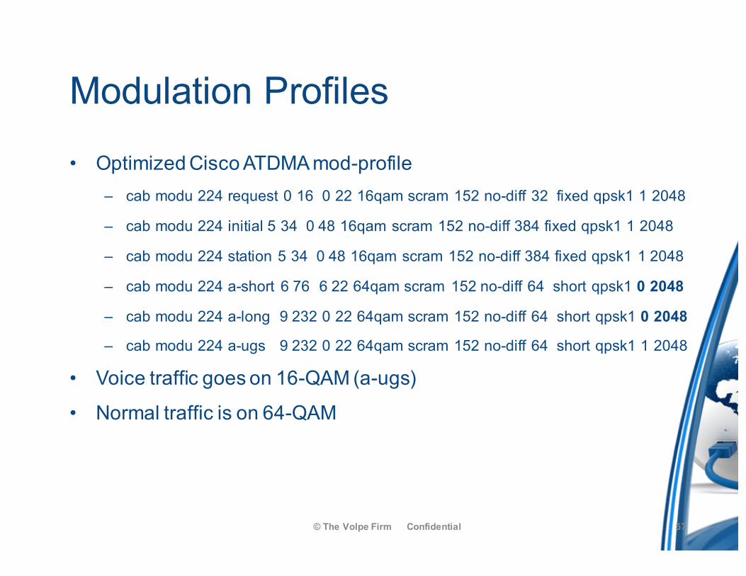
Modulation Profiles
• Optimized Cisco ATDMA mod-profile– cab modu 224 request 0 16 0 22 16qam scram 152 no-diff 32 fixed qpsk1 1 2048
– cab modu 224 initial 5 34 0 48 16qam scram 152 no-diff 384 fixed qpsk1 1 2048
– cab modu 224 station 5 34 0 48 16qam scram 152 no-diff 384 fixed qpsk1 1 2048
– cab modu 224 a-short 6 76 6 22 64qam scram 152 no-diff 64 short qpsk1 0 2048
– cab modu 224 a-long 9 232 0 22 64qam scram 152 no-diff 64 short qpsk1 0 2048
– cab modu 224 a-ugs 9 232 0 22 64qam scram 152 no-diff 64 short qpsk1 1 2048
• Voice traffic goes on 16-QAM (a-ugs)
• Normal traffic is on 64-QAM
© The Volpe Firm Confidential 57
Concerns
• Verify voice traffic is not on a-short or a-long!
• An eMTA must be at least provisioned as D1.1 or no traffic will go on a-ugs
• If MTA config file is not properly configured, voice traffic will not go on a-ugs
• Many opportunities for failure
© The Volpe Firm Confidential 58
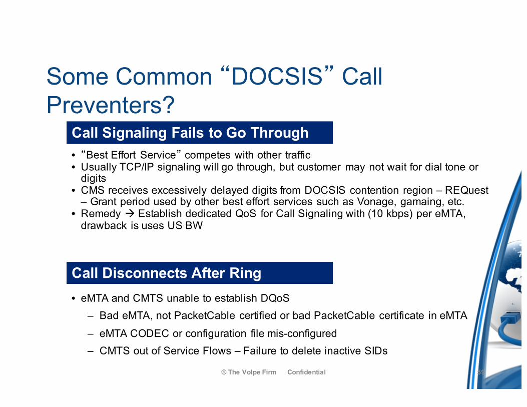
Some Common “DOCSIS” Call Preventers?
© The Volpe Firm Confidential
Call Signaling Fails to Go Through
Call Disconnects After Ring
• “Best Effort Service” competes with other traffic• Usually TCP/IP signaling will go through, but customer may not wait for dial tone or
digits• CMS receives excessively delayed digits from DOCSIS contention region – REQuest
– Grant period used by other best effort services such as Vonage, gamaing, etc.• Remedy à Establish dedicated QoS for Call Signaling with (10 kbps) per eMTA,
drawback is uses US BW
• eMTA and CMTS unable to establish DQoS– Bad eMTA, not PacketCable certified or bad PacketCable certificate in eMTA– eMTA CODEC or configuration file mis-configured– CMTS out of Service Flows – Failure to delete inactive SIDs
59
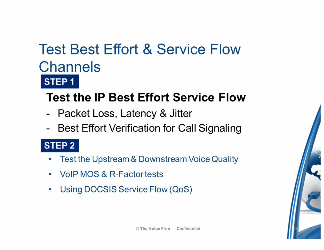
Test Best Effort & Service Flow Channels
• Test the Upstream & Downstream Voice Quality
• VoIP MOS & R-Factor tests
• Using DOCSIS Service Flow (QoS)
© The Volpe Firm Confidential
STEP 1
STEP 2
Test the IP Best Effort Service Flow- Packet Loss, Latency & Jitter- Best Effort Verification for Call Signaling
60
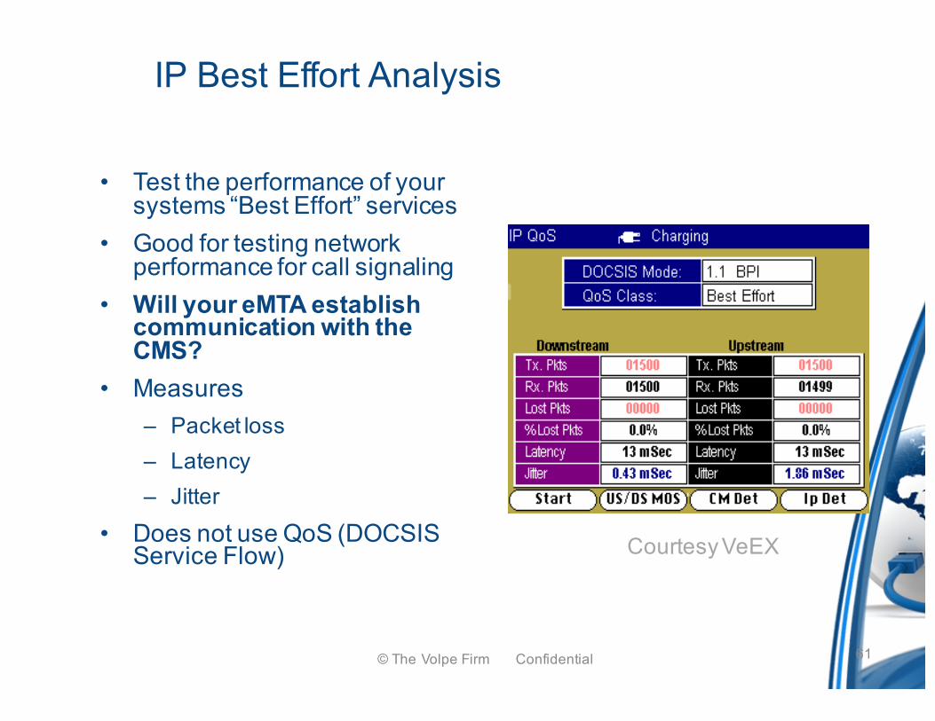
IP Best Effort Analysis
• Test the performance of your systems “Best Effort” services
• Good for testing network performance for call signaling
• Will your eMTA establish communication with the CMS?
• Measures – Packet loss– Latency– Jitter
• Does not use QoS (DOCSIS Service Flow) Courtesy VeEX
© The Volpe Firm Confidential 61
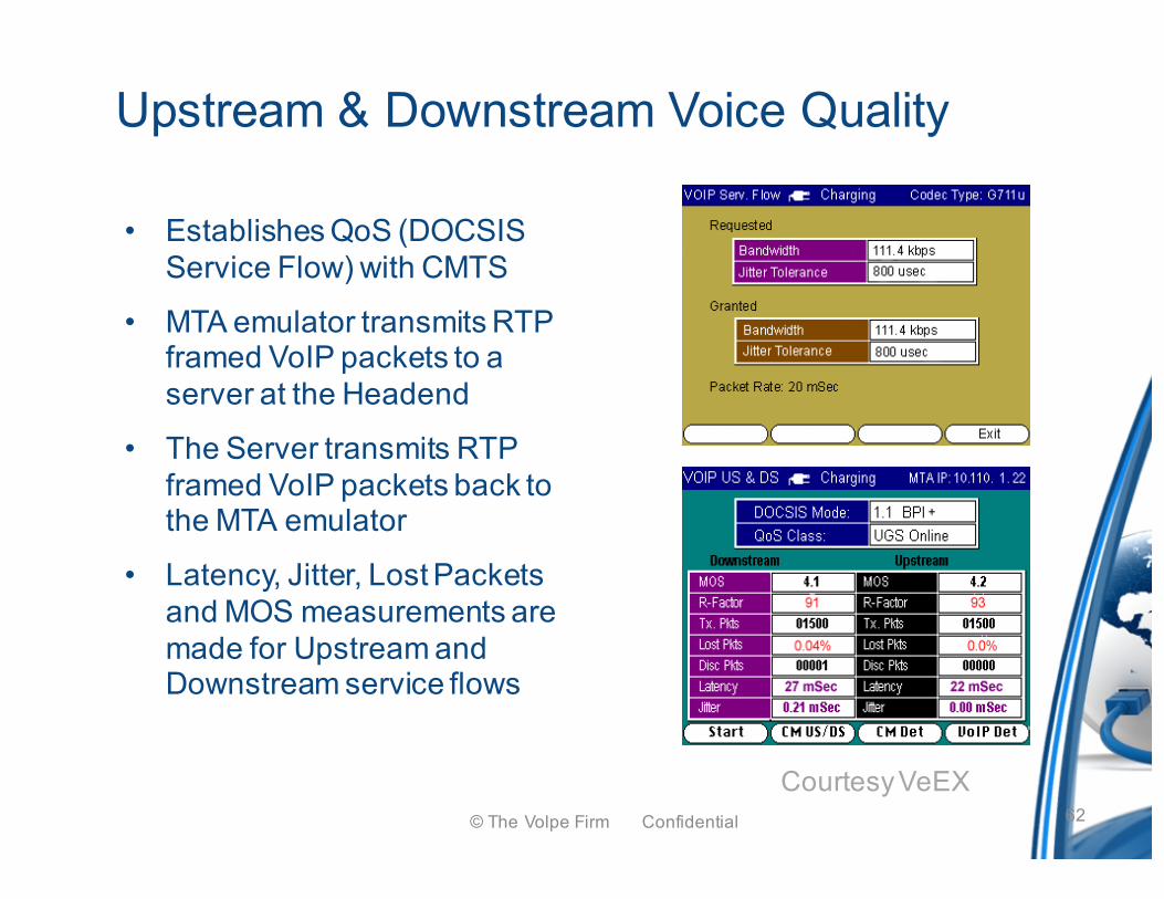
Upstream & Downstream Voice Quality
• Establishes QoS (DOCSIS Service Flow) with CMTS
• MTA emulator transmits RTP framed VoIP packets to a server at the Headend
• The Server transmits RTP framed VoIP packets back to the MTA emulator
• Latency, Jitter, Lost Packets and MOS measurements are made for Upstream and Downstream service flows
Courtesy VeEX© The Volpe Firm Confidential 62
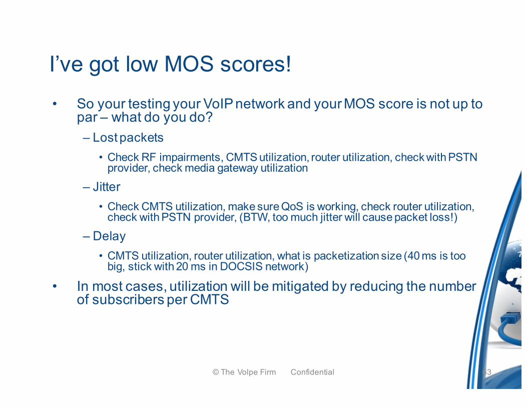
I’ve got low MOS scores!• So your testing your VoIP network and your MOS score is not up to
par – what do you do? – Lost packets
• Check RF impairments, CMTS utilization, router utilization, check with PSTN provider, check media gateway utilization
– Jitter• Check CMTS utilization, make sure QoS is working, check router utilization,
check with PSTN provider, (BTW, too much jitter will cause packet loss!)
– Delay• CMTS utilization, router utilization, what is packetization size (40 ms is too
big, stick with 20 ms in DOCSIS network)
• In most cases, utilization will be mitigated by reducing the number of subscribers per CMTS
© The Volpe Firm Confidential 63
Cause and Effect
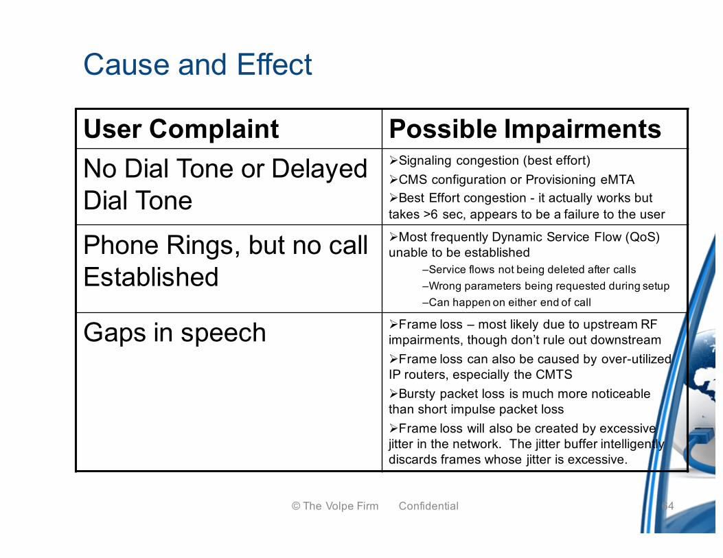
User Complaint Possible ImpairmentsNo Dial Tone or Delayed Dial Tone
ØSignaling congestion (best effort) ØCMS configuration or Provisioning eMTA ØBest Effort congestion - it actually works but takes >6 sec, appears to be a failure to the user
Phone Rings, but no call Established
ØMost frequently Dynamic Service Flow (QoS) unable to be established
–Service flows not being deleted after calls–Wrong parameters being requested during setup–Can happen on either end of call
Gaps in speech ØFrame loss – most likely due to upstream RF impairments, though don’t rule out downstreamØFrame loss can also be caused by over-utilized IP routers, especially the CMTSØBursty packet loss is much more noticeable than short impulse packet lossØFrame loss will also be created by excessive jitter in the network. The jitter buffer intelligently discards frames whose jitter is excessive.
© The Volpe Firm Confidential 64
Cause and Effect
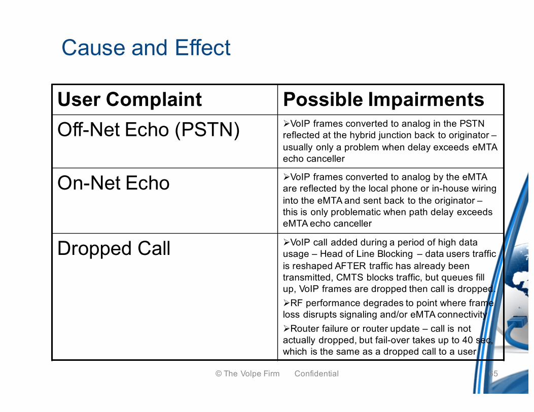
User Complaint Possible ImpairmentsOff-Net Echo (PSTN) ØVoIP frames converted to analog in the PSTN
reflected at the hybrid junction back to originator –usually only a problem when delay exceeds eMTA echo canceller
On-Net Echo ØVoIP frames converted to analog by the eMTA are reflected by the local phone or in-house wiring into the eMTA and sent back to the originator –this is only problematic when path delay exceeds eMTA echo canceller
Dropped Call ØVoIP call added during a period of high data usage – Head of Line Blocking – data users traffic is reshaped AFTER traffic has already been transmitted, CMTS blocks traffic, but queues fill up, VoIP frames are dropped then call is dropped.ØRF performance degrades to point where frame loss disrupts signaling and/or eMTA connectivityØRouter failure or router update – call is not actually dropped, but fail-over takes up to 40 sec, which is the same as a dropped call to a user
© The Volpe Firm Confidential 65
© The Volpe Firm Confidential
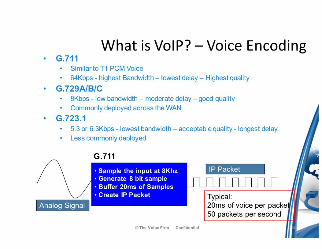
• G.711• Similar to T1 PCM Voice• 64Kbps - highest Bandwidth – lowest delay – Highest quality
• G.729A/B/C • 8Kbps - low bandwidth – moderate delay – good quality• Commonly deployed across the WAN
• G.723.1• 5.3 or 6.3Kbps - lowest bandwidth – acceptable quality - longest delay• Less commonly deployed
• Sample the input at 8Khz• Generate 8 bit sample• Buffer 20ms of Samples• Create IP Packet
G.711 IP Packet
Typical:20ms of voice per packet50 packets per second
Analog Signal
WhatisVoIP?– VoiceEncoding
66
What affects VoIP Quality of Service? (IP)
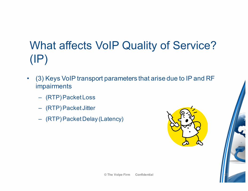
• (3) Keys VoIP transport parameters that arise due to IP and RF impairments– (RTP) Packet Loss
– (RTP) Packet Jitter
– (RTP) Packet Delay (Latency)
© The Volpe Firm Confidential 67
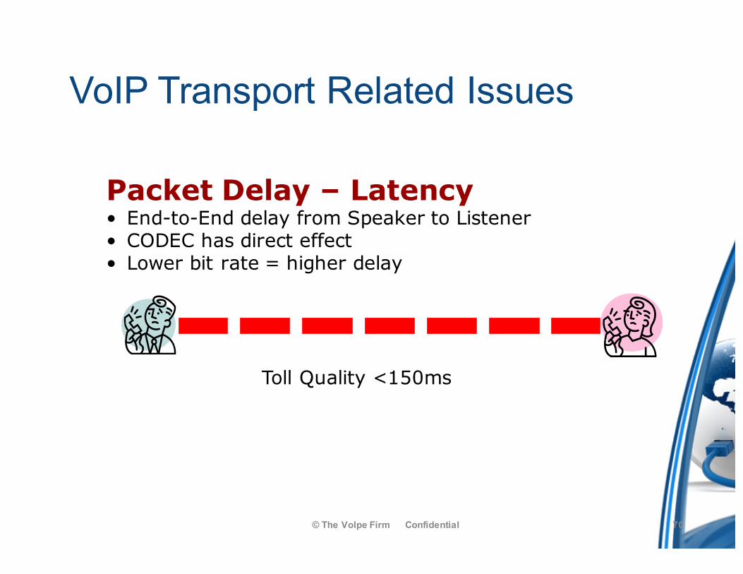
VoIP Transport Related Issues
© The Volpe Firm Confidential
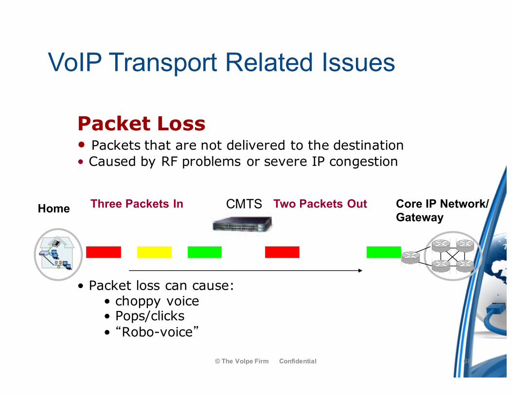
Packet Loss• Packets that are not delivered to the destination• Caused by RF problems or severe IP congestion
• Packet loss can cause:• choppy voice• Pops/clicks• “Robo-voice”
CMTSThree Packets In Two Packets OutHome Core IP Network/Gateway
68
VoIP Transport Related Issues
© The Volpe Firm Confidential
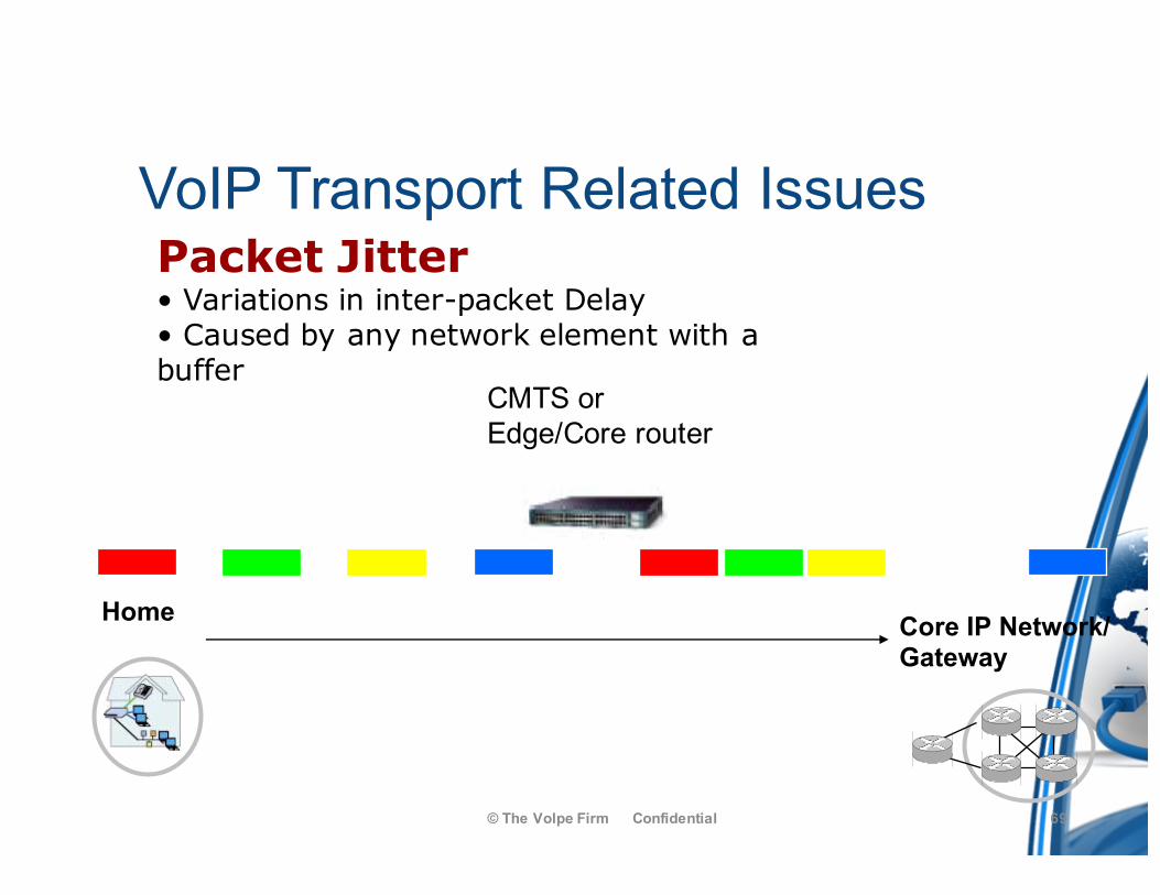
Packet Jitter• Variations in inter-packet Delay• Caused by any network element with a buffer
Packets Equally spaced
Variation in packet spacing
CMTS orEdge/Core router
Home Core IP Network/Gateway
69
VoIP Transport Related Issues
© The Volpe Firm Confidential
Packet Delay – Latency• End-to-End delay from Speaker to Listener• CODEC has direct effect• Lower bit rate = higher delay
Toll Quality <150ms
70
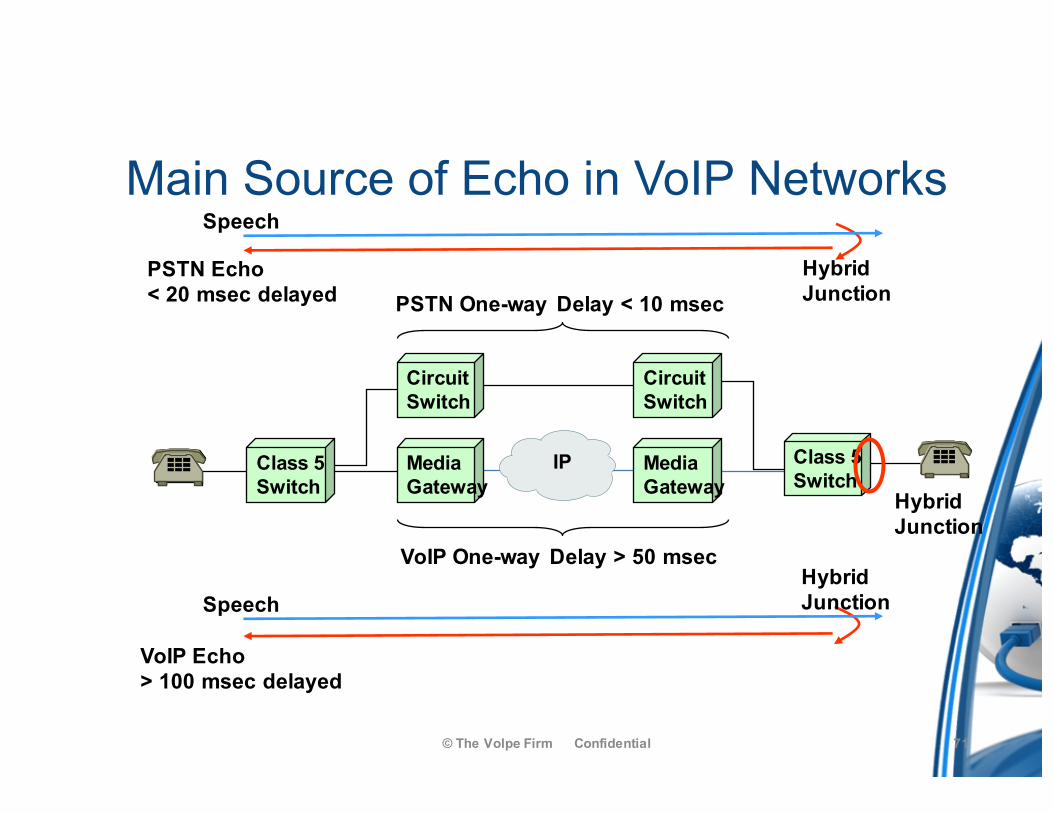
Main Source of Echo in VoIP Networks
© The Volpe Firm Confidential
HybridJunctionSpeech
VoIP Echo> 100 msec delayed
HybridJunction
Speech
PSTN Echo < 20 msec delayed
IPMediaGateway
CircuitSwitch
CircuitSwitch
MediaGateway
Class 5Switch
VoIP One-way Delay > 50 msec
PSTN One-way Delay < 10 msec
Class 5 Switch Hybrid
Junction
71
© The Volpe Firm Confidential
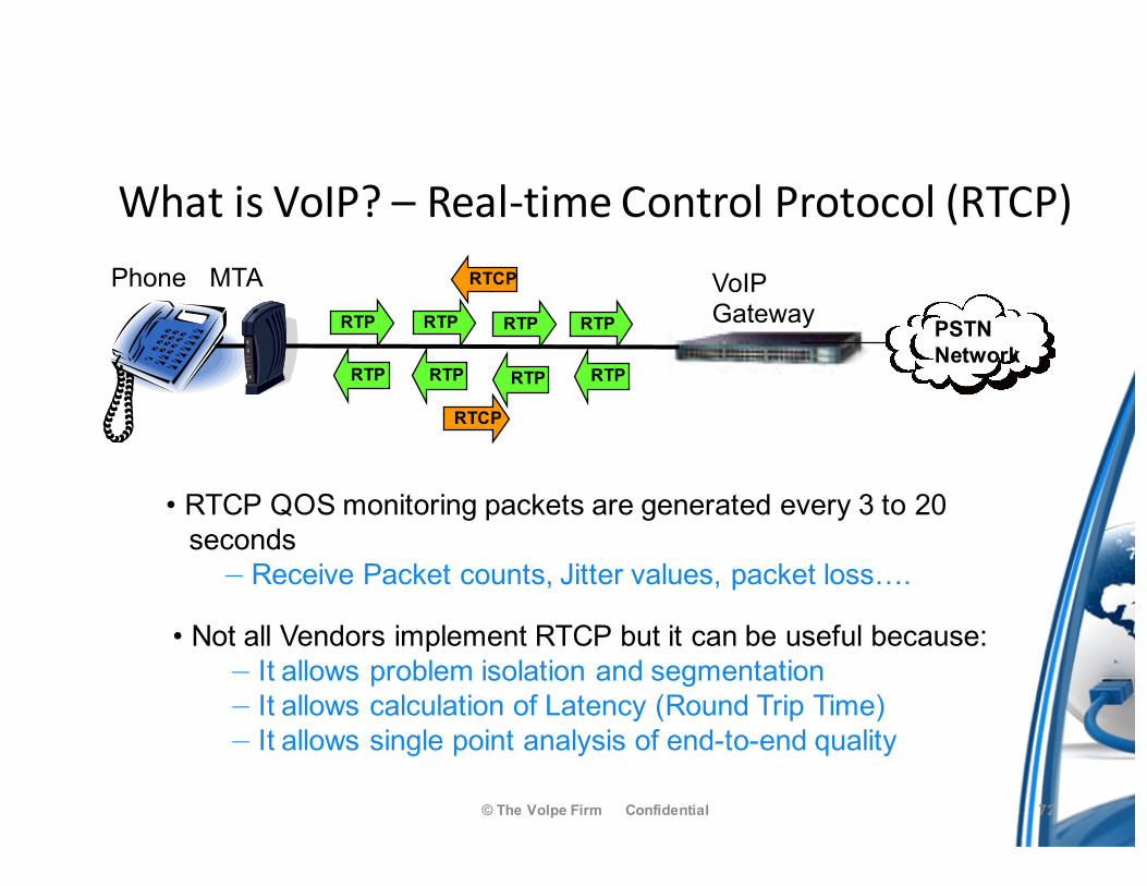
• RTCP QOS monitoring packets are generated every 3 to 20 seconds
— Receive Packet counts, Jitter values, packet loss….
Phone MTA VoIPGateway PSTN
NetworkRTPRTPRTPRTP
RTCP
• Not all Vendors implement RTCP but it can be useful because:— It allows problem isolation and segmentation— It allows calculation of Latency (Round Trip Time)— It allows single point analysis of end-to-end quality
RTP RTP RTP RTP
RTCP
WhatisVoIP?– Real-timeControlProtocol(RTCP)
72
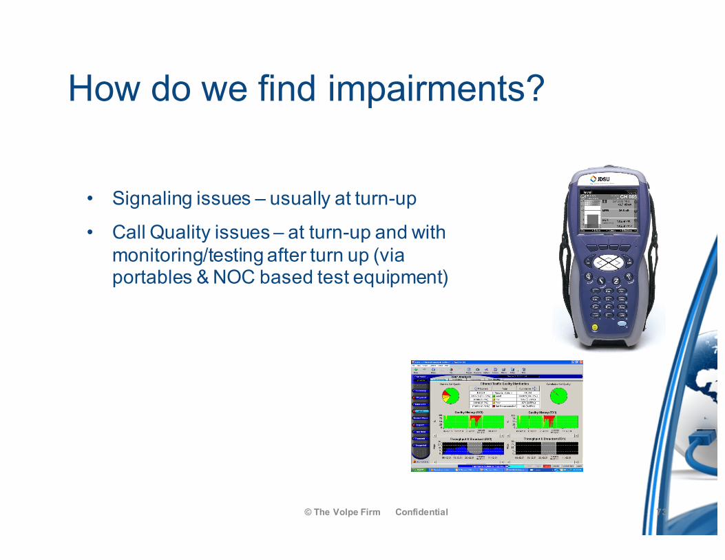
How do we find impairments?
• Signaling issues – usually at turn-up
• Call Quality issues – at turn-up and with monitoring/testing after turn up (via portables & NOC based test equipment)
© The Volpe Firm Confidential 73
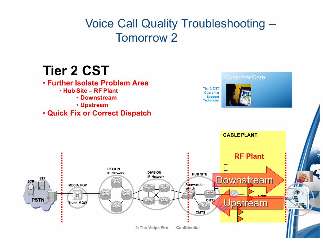
Voice Call Quality Troubleshooting –Tomorrow 2
© The Volpe Firm Confidential
CABLE PLANT
Customer Care
PSTNCable
REGIONIP Network
MEDIA POP
Trunk MGW
STPSCP
CMTS
CMTS
Aggregationswitch
HUB SITE
Tier 2 CSTCustomer
SupportTechnician
DIVISIONIP Network
RF Plant
Tier 2 CST• Further Isolate Problem Area
• Hub Site – RF Plant• Downstream• Upstream
• Quick Fix or Correct Dispatch
Upstream
Downstream
74
Summary
• 80% of VoIP problems in a DOCSIS network will be RF impairment related
• 20% are DOCSIS or IP protocol related• The RF upstream is the Achilles heel of the DOCSIS and VoIP
network – frame loss happens here first• DOCSIS and IP protocol impairments usually impact all subscribers • Impairments are cumulative
© The Volpe Firm Confidential 75
76© The Volpe Firm Confidential
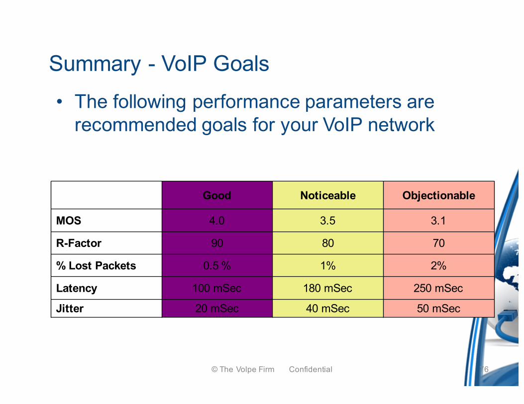
Summary - VoIP Goals• The following performance parameters are
recommended goals for your VoIP network
Good Noticeable Objectionable
MOS 4.0 3.5 3.1
R-Factor 90 80 70
% Lost Packets 0.5 % 1% 2%
Latency 100 mSec 180 mSec 250 mSec
Jitter 20 mSec 40 mSec 50 mSec
References
• ITU-T G.711 General Aspects of Digital Transmission Systems, Pulse Code Modulation (PCM) of Voice Frequencies, 1993
• ITU-T G.729 General Aspects of Digital Transmission Systems, Coding of Speech at 8 kbit/s using Conjugate-Structure Algebraic-Code-Excited Linear-Prediction (CS-ACELP), 1996
• Voice over IP (VoIP), Spirent Communications, P/N 340-1158-001 Rev A, 8/01• Delivering Voice over IP Networks, Daniel & Emma Minoli, Wiley• ITU-T G.107 The E Model, A computational model for use in transmission planning, 1993• Measuring Voice Quality, www.voiptroubleshooter.com/voiptr_mosr.htm, copyright
Telchemy Incorporated• PacketCable™ Architecture Call Flows, Technical Report On-Net MTA to PSTN Telephone,
PKT-TRCF-ON-PSTN-V02-030815, Copyright 1999-2003 Cable Television Laboratories, Inc.
• Optimizing the Future with Next-Generation DOCSIS Mechanics, Options and Issues on the Road to 2.0, Fred Dawson, 2003, Society of Cable Television Engineers (SCTE)
• Implementing VoIP: A Voice Transmission Performance Progress Report, James, Chen, and Garrison, AT&T, IEEE Communications Magazine, July 2004
• Data-Over-Cable Service Interface Specifications• DOCSIS 1.1, SP-RFIv1.1-I10-030730, CableLabs, July 2003
© The Volpe Firm Confidential 77